RESET IN THE ALARM CODES
Press the central button until it appears RES
(only available when there is at least one
active alarm).
Turn the central button to go from 0 to 1.
Press the central button one time.
After the reset, the thermostat will automatically return to normal, displaying the temperature.
IMPORTANT:
All serious alarms cause the stop of the unit and trigger an output signal through a relay.
DESCRIPTION OF THE ALARM CODES
CODIGO
AL01
Probe alarm B1 disconnected
AL06
Probe alarm B6 disconnected
ALPA
High pressure switch alarm circuit 1
ALPB
Low pressure switch alarm circuit 1
ALF7
Thermal alarm of the interior fan
ALF6
Thermal alarm of the compressor 1
ALPM
Minimum pressure switch alarm
ALRF
Lack of refrigerant alarm
AL11
Probe alarm B11 disconnected
AL12
Probe alarm B12 disconnected
ALH1
Antifreeze alarm 1
ALH2
Antifreeze alarm 2
ALH3
Antifreeze alarm 3
ALH4
Antifreeze alarm 4
A2PA
High pressure switch alarm circuit 2
A2PB
Low pressure switch alarm circuit 2
A2PM
Minimum pressure switch alarm circuit 2
A2RF
Lack of refrigerant alarm circuit 2
A2F7
Thermal alarm of the external fan 2 (machine 2 circuits)
A2F8
Thermal alarm of the interior fan (machine 2 circuits)
AL02
Probe alarm B2 disconnected
AL03
Probe alarm B3 disconnected
ALIF
Flow switch alarm
All the alarms whose causes have disappeared or have been solved,
are canceled.
When the reset is completed, the text will change to OK.
DESCRIPCIÓN
5
09.16 207683 Rev100
AT*
Общие характеристики
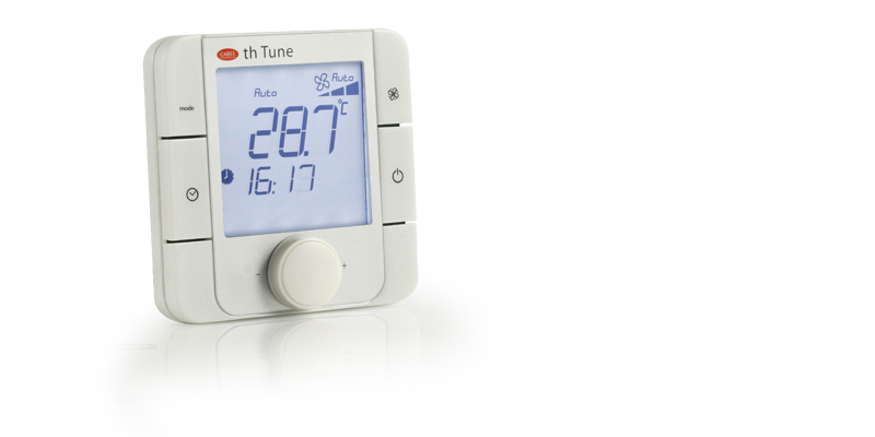
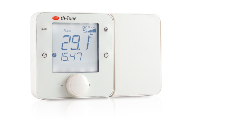
Пользовательские терминалы th-Tune предназначены для настройки температуры и влажности воздуха в жилых помещениях. В зависимости от модели терминал может оснащаться датчиком температуры или датчиком температуры/влажности и работать от сети питания переменного тока напряжением 230В или сети питания постоянного/переменного тока напряжением 24В. Терминалы th-Tune могут устанавливаться в стандартные монтажные коробки для скрытого монтажа, представленные на рынке.
Температура и влажность воздуха настраиваются просто и удобно ручкой, расположенной на лицевой стороне терминала. Кроме того, с терминала th-Tune можно настраивать некоторые параметры контроллера, например, менять режим работы и расписания. Данные управления, высвечиваемые на дисплее терминала th-Tune, полностью зависят от контроллера, к которому он подсоединен. Компактные размеры и элегантный внешний вид позволяют органично вписать такой графический терминал в любое помещение. Терминал подсоединяется к контроллеру pCO по сети RS485, работающей по протоколу Modbus.
Документация
Technical
-
2D/3D модели
Код Описание Язык Дата * Выпуск Код
2d-3d th-tune Wall mountingОписание
2D-3D drawingsЯзык
ALLДата
22/06/2015
Выпуск
R0
Код
2d-3d th-tune Flush mountingОписание
2D-3D drawingsЯзык
ALLДата
22/06/2015
Выпуск
R0
-
Руководства по эксплуатации
Код Описание Язык Дата * Выпуск Код
+0500017ARОписание
AT*-th Tune
Electronic controller for air-conditioning (wall mountng model)Язык
ARA
ENGДата
14/04/2011
Выпуск
1.1
Код
+0500017RUОписание
AT*-th Tune: Электронный контроллер для систем вентиляции и кондиционирования (настенный монтаж) / Electronic controller for air-conditioning (wall mountng model)Язык
ENG
RUSДата
13/04/2011
Выпуск
1.1
Код
+0500017IEОписание
AT*-th Tune Controllo elettronico per condizionamento (mod. a parete) / Electronic controller for air-conditioning (wall mountng model)Язык
ENG
ITAДата
13/04/2011
Выпуск
1.1
Код
+0500016RUОписание
AT* — th Tune: Электронный контроллер для систем вентиляции и кондиционирования (настенный монтаж) / Electronic controller for air-conditioning (fl ush-mount model)Язык
ENG
RUSДата
13/04/2011
Выпуск
1.2
Код
+0500016IEОписание
AT* — th Tune: Controllo elettronico per condizionamento (modello a incasso)/
Electronic controller for air-conditioning (fl ush-mount model)Язык
ENG
ITAДата
13/04/2011
Выпуск
1.2
Код
+0500016EZОписание
AT* — th Tune: 空调电子控制器(嵌入式安装)/ Electronic controller for air-conditioning (flush-mount model)Язык
CHI
ENGДата
13/04/2011
Выпуск
1.2
Commercial
-
Other related documentation
Код Описание Язык Дата * Выпуск Код
+800004031Описание
Solutions for Air Handling Units: Technology and expertise for indoor air quality and energy savingЯзык
ENGДата
05/04/2023
Выпуск
1.2
Код
+800004030Описание
Soluzioni per Unità Trattamento Aria: Tecnologia e competenza per la qualità dell’aria e il risparmio energeticoЯзык
ITAДата
05/04/2023
Выпуск
1.2
Images
-
High resolution images
Код Описание Язык Дата * Выпуск Код
PH10LAT301-th-tune-power-supplyОписание
th-Tune-CAREL-Terminals-Room TerminalsЯзык
ALLДата
02/09/2021
Выпуск
R.0
Код
PH09LAT301-th-tune-standardОписание
th-Tune-CAREL-Terminals-Room TerminalsЯзык
ALLДата
02/09/2021
Выпуск
R.0
Operation & User’s Manual for Carel TH Tune Control Systems, Touch terminals (6 pages)
Specifications:954/954535-th_tune.pdf file (05 Feb 2023) |
Accompanying Data:
Carel TH Tune Control Systems, Touch terminals PDF Operation & User’s Manual (Updated: Sunday 5th of February 2023 06:03:32 PM)
Rating: 4.5 (rated by 96 users)
Compatible devices: PLD Series, pGD touch 7, pGDx Touch 4.3”, PlantVisorPRO, MPXone series, Hecu CO2, m chiller, humiFog.
Recommended Documentation:
Text Version of Carel TH Tune Operation & User’s Manual
(Ocr-Read Summary of Contents, UPD: 05 February 2023)
-
2, 2 09.16 207683 Rev100 INDEX INSTALATION INSTRUCTIONS …………………………………………………………………………………………………………………. 3 OPERATING MANUAL ……………………………………………………………………………………..…
-
4, Carel TH Tune 4 09.16 207683 Rev100 OPERATING MANUAL ON / OFF Hold the button (On / Off) for two seconds to turn on or turn off the thermostat. The word “OFF” will be shown on the screen when the thermostat is turned off. NOTE: If the on-off remote contact is opened, the thermostat will show “…
-
5, Carel TH Tune 5 09.16 207683 Rev100 DESCRIPTION OF ALARM CODES RESET IN THE ALARM CODES Press the central button until it appears RES (only available when there is at least one active alarm). All the alarms whose causes have disappeared or have been solved, are canceled. …
-
6, 6 09.16 207683 Rev100 TIME SCHEDULE AND FUNCTIONS CLOCK BUTTON (1): Normal / Short press: the function activate and deactivate the time schedule. A clock icon appears when the time schedule is activated. Long press: It has effect only when w…
-
Carel TH Tune User Manual
-
Carel TH Tune User Guide
-
Carel TH Tune PDF Manual
-
Carel TH Tune Owner’s Manuals
Recommended Instructions: M200-107TC, TGR38, TRITON


-
toscano TPM6-DRAIN
ed.1TPM6-DRAINquick guideoverviewPower supply230/400Vac — 50/60HzPilot lights (LED) Pump running, High level alarm, Maximum current, Minimum current, Timer, Pump alarmProtections Overload, Underload, Phase loss, Jammed impellerDisplayed information (4-digit LED display) Pump consumption, Maximum current, Minimum current, Timer, Alarms, SettingsPump output12A maximum (up to 40A with a …
TPM6-DRAIN 4
-
National Instruments NI TB-2641
INSTALLATION INSTRUCTIONSNI TB-26418 × 64 1-Wire Matrix Terminal Block for the NI PXI-2532IntroductionThe NI TB-2641 terminal block configures the NI PXI-2532 as an 8 × 64 1-wire matrix. The NI TB-2641 has ribbon cable headers to connect signals to the switch, and it provides optional isolation resistors to protect the reed relay from capacitive loads.Refer to the NI Switches Getting Sta …
NI TB-2641 8
-
DT Research DT410
DT410ENGLISHHandheld POS TerminalBASIC OPERATION GUIDEDT410ENGLISH 4signage dtri comDT Research, Inc.2000 Concourse Drive, San Jose, CA 95131 hp://www.dtresearch.comCopyright © 2011, DT Research, Inc. All Rights Reserved. DT Research is registered trademark of DT Research, Inc.INTRODUCTIONThank you for acquiring the DT410, part of the POS Handheld line. The DT410 offers a 3.5 outdoor-vie …
DT410 2
Popular Right Now:
Operating Impressions, Questions and Answers:
Подробнее устранение неисправностей описано в руководстве по эксплуатации каждой модели.
На нашем сайте представлены запасные части для оборудования Carel.
Для подбора запасных частей Carel сообщите нам полную маркировку блока и наименование запчасти любым удобным способом.
Коды ошибок управляющих блоков для систем вентиляции и кондиционирования Carel (PCOxs электро)
| Код | Описание ошибки |
|---|---|
| E01 | Поступил сигнал от пожарной сигнализации |
| E02 | Неисправен датчик наружной температуры |
| E03 | Неисправен датчик температуры в помещении |
| E04 | Неисправен датчик температуры приточного воздуха |
| E05 | Неисправен датчик температуры возвращаемого теплоносителя |
| E08 | Неисправен датчик температуры возвращаемого теплоносителя после нагревателя второго нагрева |
| E09 | Неисправен датчик влажности приточного воздуха |
| E10 | Неисправен датчик влажности воздуха в помещении |
| E12 | Неисправен датчик температуры насыщения |
| E13 | Один или несколько аналоговых входов под ручным управлением |
| E14 | Один или несколько аналоговых выходов под ручным управлением |
| E15 | Один или несколько дискретных входов под ручным управлением |
| E16 | Один или несколько дискретных выходов под ручным управлением |
| E17 | Нет сигнала статуса от приточного вентилятора |
| E18 | Нет сигнала статуса от вытяжного вентилятора |
| E19 | Нет сигнала статуса от вытяжного и (или) приточного вентилятора |
| E20 | Низкая наружная температура для использования режима «лето» |
| E21 | Запуск заблокирован. Низкая температура возвращаемого теплоносителя или клапан в контуре нагревателя открыт менее чем на 80% (или иное значения согласно St13) |
| E22 | Защита от замерзания водяного нагревателя. Предварительная тревога |
| E23 | Защита от замерзания водяного нагревателя. Основная тревога |
| E24 | Неисправен насос в контуре водяного нагревателя |
| E25 | Защита от замерзания водяного нагревателя второго нагрева. Предварительная тревога |
| E26 | Защита от замерзания водяного нагревателя второго нагрева. Основная тревога |
| E27 | Неисправен насос в контуре водяного нагревателя 2 |
| E28 | Перегрев электронагревателя |
| E29 | Активировано оттаивание рекуператора |
| E30 | Неисправен привод ротора рекуператора |
| E31 | Неисправен компрессорно-конденсаторный агрегат (ККА) |
| E32 | Фильтр на притоке загрязнен |
| E33 | Фильтр на вытяжке загрязнен |
| E34 | Фильтр загрязнен |
| E37 | Отсутствует связь с платой расширения |
| E39 | Получен внешний сигнал тревоги |
| E40 | Перезапуск после подачи питания |
| E41 | Термозащита приточного вентилятора |
| E42 | Термозащита вытяжного вентилятора |
| E43 | Термозащита вентиляторов |
-
Contents
Table of Contents -
Bookmarks
Quick Links
USER’S MANUAL
pGD1(A18)
th-Tune (A17)
Automatic control system for the VUTR air handling units
Related Manuals for Vents th-Tune
Summary of Contents for Vents th-Tune
-
Page 1
USER’S MANUAL pGD1(A18) th-Tune (A17) Automatic control system for the VUTR air handling units… -
Page 2: Table Of Contents
The manual contains information about the purpose, technical details, operating principle, design, and installation of the th-Tune (A17) and pGD1 (A18) unit (-s) and all of its (their) modifications. Technical and maintenance staff must have theoretical and practical training in the field of ventilation systems and should be able to work in accordance with workplace safety rules as well as construction norms and standards applicable in the territory of the country.
-
Page 3: Safety Requirements
SAFETY REQUIREMENTS • Please read the user’s manual carefully prior to installing and operating the unit. • All user’s manual requirements as well as the provisions of all the applicable local and national construction, electrical, and technical norms and standards must be observed when installing and operating the unit. •…
-
Page 4: Purpose
Cable AWG 20 or AWG 22 up to 500 m twister pair AWG 22 up to 500 m Ingress protection IP20 IP40 OVERALL DIMENSIONS OF THE TH-TUNE (A17) CONTROL PANEL 22,5 OVERALL DIMENSIONS OF THE PGD1 (A18) CONTROL PANEL www.ventilation-system.com…
-
Page 5: Installation And Set-Up
INSTALLATION AND SET-UP INSTALLATION OF THE TH-TUNE (A17) CONTROL PANEL To install the rear part of the control panel, use a suitable mounting box (minimum diameter of 65 mm and minimum depth of 31 mm). 1. Use a screwdriver to pull the front and the rear sides of the 2.
-
Page 6
(A17) and pGD1 (A18) INSTALLATION OF THE PGD1 (A18) CONTROL PANEL Connect the pGD1 control panel to the controller connector using the 6P6C (PLUG-6P6C-P-C2) phone plug. The maximum length of the phone cable is 50 m. To mount the control panel on a wall, route the phone cable to the selected location. -
Page 7: Control
Press ESC to exit and return to the standard display mode. After 10 seconds the th-Tune returns to the main menu automatically. Unit switching on/off. In some menus a short pressing has the same function as ESC.
-
Page 8
(A17) and pGD1 (A18) PGD1 CONTROL PANEL Control with a pGD1 control panel is identical to unit control with a controller. The main page of the control panel menu displays the following information: • date and current time •… -
Page 9
CONTROLLER FUNCTIONS AND MENU The controller has the following controls and indicators: • Backlit LCD display. The display screen shows the current parameters of the system operation, temperature values, pre-set parameters and alarms. • Buttons: control elements for operation of the controller. 6P6C telephone connector The 6P6C connector (PLUG-6P6C-P-C2) is designed for connection of the pGD1 control panel using the telephone cable. -
Page 10
(only for the A17 control panel) When connecting the th-Tune control panel, the additional menu item «Scheduler» will be displayed in the controller main menu. To modify the unit operation parameters, move the cursor to the required line using the button. -
Page 11
UNIT OPERATION MODE SELECTION The unit has 4 operation modes. To select the desired mode, place the cursor on the «Mode» word using the button. Then use to set the desired value and then press to confirm. – the fans and the heat exchanger are disabled. –… -
Page 12
(A17) and pGD1 (A18) UNIT PARAMETERS To enter the user parameter menu, press the button. Use to select the desired menu item and press to enter. 1. SYSTEM INFORMATION PAGE 1/3 CONTAINS THE FOLLOWING PARAMETERS: To view the system information, enter the user parameter menu INFO». -
Page 13
SCHEDULE SETUP (ONLY FOR THE PGD1 CONTROL PANEL) WHEN USING TH-TUNE, THE SCHEDULE IS SET UP ACCORDING TO THE TH-TUNE CONTROL PANEL DESCRIPTION. 1. DAY SELECTION 2. SETTING THE SCHEDULE RECORDING START TIME to select the «Day»… -
Page 14
(A17) and pGD1 (A18) DEFINING EXCEPTION PERIODS PAGE 2/4 DEFINING EXCEPTION PERIODS While in the Scheduled operation mode you may need to create To select a parameter, press a different scheduled operation period between the two set Then use to set the desired parameter value. -
Page 15
If the unit serves a number of spaces, the parameter value AIR». should be set to «EXHAUST «IN THE TH-TUNE» the control When selecting the parameter panel must be installed in spaces where the air is supplied by the unit. SETTING UP TEMPERATURE SETPOINTS Press to select a temperature setpoint. -
Page 16
(A17) and pGD1 (A18) SENSOR OPERATION SETUP You may enable/disable the humidity sensor in the exhaust air duct via software in the parameter. — enable/disable outdoor sensor 0-10 V: — change the input type of the outdoor relay humidity sensor. -
Page 17
FILTER REPLACEMENT. When filter replacement is required, the system will generate a filter replacement alert. When this message appears, maintain or replace filters and reset the hour meter in the controller menu (p. 22). ALARM CODES ALARM CODE DESCRIPTION Fire alarm Е02 Intake air sensor failure Е04… -
Page 18
(A17) and pGD1 (A18) www.ventilation-system.com… -
Page 19
www.ventilation-system.com… -
Page 20
V159-2EN-02(Carel)