-
Page 1
● Protections DEIF A/S · Frisenborgvej 33 · DK-7800 Skive · Tel.: +45 9614 9614 · Fax: +45 9614 9615 · info@deif.com · www.deif.com isenborgvej 33 · DK-7800 Skive · Tel.: +45 9614 9614 · Fax: +45 9614 9615 · info@deif.com · www.deif.com Document no.: 4189340786B… -
Page 2: Table Of Contents
CGC 400 DRH 4189340786 UK 1. General information 1.1. Warnings, legal information and safety………………..5 1.1.1. Warnings and notes ……………………5 1.1.2. Legal information and disclaimer ………………..5 1.1.3. Safety issues ……………………..5 1.1.4. Electrostatic discharge awareness ………………..5 1.1.5. Factory settings ……………………..6 1.2. About the designer’s reference handbook………………..6 1.2.1.
-
Page 3
CGC 400 DRH 4189340786 UK 4.7. Flowcharts……………………….20 4.7.1. Flowcharts………………………20 4.7.2. Mode shift……………………….21 4.7.3. MB open sequence……………………22 4.7.4. GB open sequence……………………23 4.7.5. Stop sequence……………………..24 4.7.6. Start sequence……………………..25 4.7.7. MB close sequence……………………26 4.7.8. GB close sequence……………………27 4.7.9. Load takeover……………………..28 4.7.10. Island operation…………………….29 4.7.11. -
Page 4
CGC 400 DRH 4189340786 UK 7.12.1. Max. ventilation alarm……………………65 7.13. Not in auto……………………….65 7.14. Fuel pump logic……………………..65 7.14.1. Fuel fill check……………………..66 7.15. Fail class……………………….67 7.15.1. Fail class……………………….67 7.15.2. Engine running………………………67 7.15.3. Engine stopped……………………..68 7.15.4. Fail class configuration………………….68 7.16. Service timers………………………..69 7.17. -
Page 5: General Information
1.1.2 Legal information and disclaimer DEIF takes no responsibility for installation or operation of the generator set. If there is any doubt about how to install or operate the engine/generator controlled by the unit, the company responsible for the installation or the operation of the set must be contacted.
-
Page 6: Factory Settings
CGC 400 DRH 4189340786 UK General information 1.1.5 Factory settings The unit is delivered from factory with certain factory settings. These are based on average values and are not necessarily the correct settings for matching the engine/generator set in question. Precautions must be taken to check the settings before running the engine/generator set.
-
Page 7: General Product Information
For detailed specifications of the hardware, please refer to the datasheet. 2.3 Options 2.3.1 Options When ordering the CGC 400, it comes with a number of features, which were options in the other DEIF prod- ucts. The customer cannot add or remove any of these features/options.
-
Page 8: Passwords
CGC 400 DRH 4189340786 UK Passwords 3. Passwords 3.1 Passwords and parameter access 3.1.1 Password The unit includes three password levels. All levels can be adjusted in the PC software. Available password levels: Password level Factory setting Access Customer Service…
-
Page 9: Parameter Access
CGC 400 DRH 4189340786 UK Passwords The password level can also be changed from the parameter view in the column «Level». 3.1.2 Parameter access To gain access to adjust the parameters, the password level must be entered: If the password level is not entered, it is not possible to enter the parameters.
-
Page 10: Functional Descriptions
CGC 400 DRH 4189340786 UK Functional descriptions 4. Functional descriptions 4.1 Standard functions 4.1.1 Standard functions This section includes functional descriptions of standard functions as well as illustrations of the relevant appli- cation types. Flowcharts and single-line diagrams will be used in order to simplify the information.
-
Page 11: Busbar Protection (Ansi)
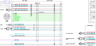
Please see the Installation Instructions for terminal strip overview and rear side controller view. 4.3 Measurement systems The CGC 400 is designed for measurement of voltages between 100 and 480V AC. For further reference, the AC wiring diagrams are shown in the Installation Instructions. In menu 9130, the measurement principle can be changed between three-phase, single phase and split phase.
-
Page 12: Split Phase System
CGC 400 DRH 4189340786 UK Functional descriptions Setting Adjustment Description Adjust to value 6004 G nom. voltage Phase-neutral voltage of the generator 230V AC 6041 G transformer Primary voltage of the G voltage transformer (if installed) x √3 6042 G transformer Secondary voltage of the G voltage transformer (if installed) x √3…
-
Page 13: Applications
CGC 400 DRH 4189340786 UK Functional descriptions The following adjustments must be made to make the system ready for the three-phase measuring (example 400/230V AC): Setting Adjustment Description Adjust to value 6004 G nom. voltage Phase-phase voltage of the generator…
-
Page 14
The product will be automatically selected if you are currently connected to the unit when doing this configu- ration. When using the CGC 400, the plant type will be stuck to «Single DG». This means no CAN communication can be established with other units. -
Page 15: Amf (No Back Synchronisation)
CGC 400 DRH 4189340786 UK Functional descriptions For each area, it is defined whether a generator and a mains are present, and the number and type of break- ers. If a CGC 412 is currently connected, it will not be possible to draw an application with a mains or a mains breaker.
-
Page 16: Island Operation
2. Digital inputs 3. Modbus command at service port or RS485 The standard CGC 400 is only equipped with a limited number of digital inputs, please refer to «Digital inputs» in this document and the data sheet for additional information about availabili-…
-
Page 17: Test Mode
CGC 400 DRH 4189340786 UK Functional descriptions Command Description Comment Start The start sequence is initiated and continues until the genset starts or the maximum number of start attempts has been reached. If Hz/V OK the GB is ready to close.
-
Page 18: Block Mode
The genset can be started from the local engine control panel, if such is installed. Therefore, DEIF recommends avoiding local cranking and starting of the genset. The genset will shut down if block mode is selected while the genset is running.
-
Page 19: Automatic Mains Failure
CGC 400 DRH 4189340786 UK Functional descriptions 4.6.2 Automatic Mains Failure Load Controller 4.6.3 Island operation Load Controller DEIF A/S Page 19 of 96…
-
Page 20: Load Takeover
CGC 400 DRH 4189340786 UK Functional descriptions 4.6.4 Load takeover Load Controller 4.7 Flowcharts 4.7.1 Flowcharts Using flowcharts, the principles of the most important functions will be illustrated in the next sections. The functions included are: ● Mode shift ●…
-
Page 21: Mode Shift
CGC 400 DRH 4189340786 UK Functional descriptions 4.7.2 Mode shift Start Mode shift enabled Plant mode not Island and AMF Mains failure Initiate AMF sequence Mains OK timer Initiate mains MB close Continue in timed out return sequence sequence selected mode To enable mode shift, a digital input has to be set up.
-
Page 22: Mb Open Sequence
CGC 400 DRH 4189340786 UK Functional descriptions 4.7.3 MB open sequence Start MB closed Load take Mains failure over Open MB Alarm ”MB MB opened open failure” DEIF A/S Page 22 of 96…
-
Page 23: Gb Open Sequence
CGC 400 DRH 4189340786 UK Functional descriptions 4.7.4 GB open sequence Start Stop conditions Is GB closed Open GB GB opened Alarm DEIF A/S Page 23 of 96…
-
Page 24: Stop Sequence
CGC 400 DRH 4189340786 UK Functional descriptions 4.7.5 Stop sequence Start Stop conditions GB open seq OK AUTO mode Cooldown timer run out Run coil Stop relay Deactivate Activate stop run coil relay Genset Alarm stopped DEIF A/S Page 24 of 96…
-
Page 25: Start Sequence
CGC 400 DRH 4189340786 UK Functional descriptions 4.7.6 Start sequence Start Start condition Start prepare timer Start relay Start relay timer Genset started timeout Off relay Run feedback Alarm detected Stop relay timer F/U OK timed out Max start Ready to…
-
Page 26: Mb Close Sequence
CGC 400 DRH 4189340786 UK Functional descriptions 4.7.7 MB close sequence Start MB open GB open GB open GB open sequence failure Mains Mains failure MB close Close MB failure DEIF A/S Page 26 of 96…
-
Page 27: Gb Close Sequence
CGC 400 DRH 4189340786 UK Functional descriptions 4.7.8 GB close sequence Start GB open Start seq OK Volt/ freq MB open MB open MB open failure sequence Mains Mains failure GB close Close GB failure DEIF A/S Page 27 of 96…
-
Page 28: Load Takeover
CGC 400 DRH 4189340786 UK Functional descriptions 4.7.9 Load takeover Start Activate start input Start sequence MB open sequence Genset operation GB close sequence Deactivate start input GB open MB close Stop sequence sequence sequence DEIF A/S Page 28 of 96…
-
Page 29: Island Operation
CGC 400 DRH 4189340786 UK Functional descriptions 4.7.10 Island operation Start Start input active Start sequence GB close Operation sequence Start input deactivated GB open sequence Stop sequence DEIF A/S Page 29 of 96…
-
Page 30: Automatic Mains Failure, Amf
CGC 400 DRH 4189340786 UK Functional descriptions 4.7.11 Automatic Mains Failure, AMF Start Mains failure #7065: start eng + open MB Open MB Start sequence Start sequence Open MB GB close GB close sequence sequence Mains ok MB close Time out…
-
Page 31: Test Sequence
CGC 400 DRH 4189340786 UK Functional descriptions 4.7.12 Test sequence Start Select test mode Simpel test Full test Start Start sequence sequence Open MB Close GB Test timer Test timer sequence sequence Timer run out Stop sequence Return to running mode,…
-
Page 32: Sequences
CGC 400 DRH 4189340786 UK Functional descriptions 4.8 Sequences 4.8.1 Sequences The following contains information about the sequences of the engine, the generator breaker, and the mains breaker. These sequences are automatically initiated if the auto mode is selected. In the manual mode, the selected sequence is the only sequence initiated (e.g. press the START push-but- ton: the engine will start, but not close the breaker).
-
Page 33: Start Sequence
CGC 400 DRH 4189340786 UK Functional descriptions 4.8.2 Start sequence The following drawings illustrate the start sequences of the genset with normal start prepare and extended start prepare. No matter the choice of start prepare function, the run coil is activated before the start relay (starter). The time between the run coil and the start relay is setup in parameter 6151.
-
Page 34: Start Sequence Conditions
CGC 400 DRH 4189340786 UK Functional descriptions Start sequence: Extended start prepare Start prepare Crank (starter) Run coil 1 sec. Stop coil Running feedback 1st start attempt 2nd start attempt 3rd start attempt 4.8.3 Start sequence conditions The start sequence initiation can be controlled by the following conditions: ●…
-
Page 35: Running Feedback
CGC 400 DRH 4189340786 UK Functional descriptions The diagram below shows an example where the RMI signal builds up slowly, and starting is initiated at the end of the third start attempt. Start sequence Cranking depends on RMI Start prepare…
-
Page 36
CGC 400 DRH 4189340786 UK Functional descriptions The sequence is shown in the diagram below. Running feedback failure Primary running feedback Secondary running feedback 1sec Start relay (crank) Alarm Alarm Interruption of start sequence The start sequence is interrupted in the following situations:… -
Page 37
CGC 400 DRH 4189340786 UK Functional descriptions If MPU is chosen as the primary running feedback, this alarm will be raised if the specified rpm is not reached before the delay has expired. — Run feedback failure (4540 Run feedb. fail) If running is detected on the frequency (secondary), but the primary running feedback, e.g. -
Page 38: Stop Sequence
CGC 400 DRH 4189340786 UK Functional descriptions 4.8.5 Stop sequence The drawings illustrate the stop sequence. Stop sequence Run coil Cooling down time COOL stop Run coil Running feedback Sequence initiated Stop sequence Stop coil Cooling down time COOL Stop coil…
-
Page 39
CGC 400 DRH 4189340786 UK Functional descriptions Description Cooling Stop Comment down Auto mode stop Trip and stop alarm Stop button on display Manual. Cooling down is interrupted if the stop button is activated twice. Remove «auto start/stop» X Auto mode: island operation and load takeover. -
Page 40: Breaker Sequences
CGC 400 DRH 4189340786 UK Functional descriptions If the cooling-down temperature is set to 0 deg., the cooling-down sequence will be entirely controlled by the timer. 4.8.6 Breaker sequences The breaker sequences will be activated depending on the selected mode:…
-
Page 41
CGC 400 DRH 4189340786 UK Functional descriptions Timer Description Menu number Mains failure delay 7070 f mains failure 7060 U mains failure Frequency/voltage OK 6220 Hz/V OK Mains failure OK delay 7070 f mains failure 7060 U mains failure GB ON delay… -
Page 42
CGC 400 DRH 4189340786 UK Functional descriptions Example 2: 7065 Mains fail control: Start engine Mains OK MB On GB On Gen start seq Gen stop seq Gen running Gen f/U OK Mains failure Mains OK detected Conditions for breaker operations The breaker sequences react depending on the breaker positions and the frequency/voltage measurements. -
Page 43: Display And Menu Structure
5. Display and menu structure 5.1 Reference to operator’s manual Information about display and menu structure can be found in the «Operator’s manual», which is located on DEIF’s homepage under documentation for CGC 400. DEIF A/S Page 43 of 96…
-
Page 44: Engine Communication
6. Engine communication 6.1 Reference to H5 manual 6.1.1 Engine communication Information about engine communication can be found in the «Option H5 and H7» manual, which is located on DEIF’s homepage under documentation for CGC 400. DEIF A/S Page 44 of 96…
-
Page 45: Additional Functions
CGC 400 DRH 4189340786 UK Additional functions 7. Additional functions 7.1 Start functions 7.1.1 Start functions The controller will start the genset when the start command is given. The start sequence is deactivated when the remove starter event occurs or when the running feedback is present.
-
Page 46: Analogue Tacho Feedback
CGC 400 DRH 4189340786 UK Additional functions Run. feedback Firing speed The diagram illustrates how the digital running feedback is activated when the engine has reached its firing speed. Remove starter When the digital remove starter input is present, the start relay is deactivated, and the starter motor will be disengaged.
-
Page 47: Oil Pressure
CGC 400 DRH 4189340786 UK Additional functions Running feedback The diagram below shows how the running feedback is detected at the firing speed level. The factory setting is 1000 RPM (6170 Running detect.). Run. feedback, menu 4301 Firing speed Notice that the factory setting of 1000 RPM is higher than the RPM level of starter motors of typical design.
-
Page 48
CGC 400 DRH 4189340786 UK Additional functions Multi-input 58 and 59 cannot be used for this purpose. When the oil pressure increases above the adjusted value (6175 Pressure level), the running feedback is detected, and the start sequence is ended. -
Page 49: Phase Sequence Error
CGC 400 DRH 4189340786 UK Additional functions 7.2 Phase sequence error 7.2.1 Description of phase sequence error Prior to closing a breaker, the unit checks that the phase sequence is correct, depending on the chosen phase direction in parameter 2154: «phase rotation». If it is incorrect (reversed), an alarm will be issued, and the breaker in question will not be closed.
-
Page 50: Principle
CGC 400 DRH 4189340786 UK Additional functions A load time setpoint for the GB/TB and MB control for breakers with no feedback indicating that the spring is loaded. After the breaker has been opened, it will not be allowed to close again before the delay has expired.
-
Page 51: Alarm Inhibit
CGC 400 DRH 4189340786 UK Additional functions 7.5 Alarm inhibit In order to select when the alarms are to be active, a configurable inhibit setting for each alarm has been made. The inhibit functionality is a way to make an alarm inactive when the events, chosen in the menu be- low, are active.
-
Page 52
CGC 400 DRH 4189340786 UK Additional functions Selections for alarm inhibit: Function Description Inhibit 1 M-Logic outputs: Conditions are programmed in M-Logic Inhibit 2 Inhibit 3 GB ON (TB ON) The generator breaker is closed GB OFF (TB ON) The generator breaker is open… -
Page 53: Run Status (6160)
CGC 400 DRH 4189340786 UK Additional functions In this example, inhibit is set to Not run status and GB ON. Here, the alarm will only be active when the gen- erator is running and disabled again when the GB is closed.
-
Page 54: Access Lock
CGC 400 DRH 4189340786 UK Additional functions Run. feedback Alarms active The timer is ignored if digital running feedback is used. 7.6 Access lock The purpose of access lock is to deny the operator the possibility to configure the unit parameters and change the running modes from the display and digital inputs.
-
Page 55
CGC 400 DRH 4189340786 UK Additional functions Display Button Button icon Button status Comment START Not active STOP Not active GB ON Not active GB OFF Not active MB ON Not active MB OFF Not active TEST Not active AUTO… -
Page 56: Digital Mains Breaker Control
CGC 400 DRH 4189340786 UK Additional functions The following digital input functions are affected when access lock is activated: Digital input name Input status Comment Remote Start Not active Remote Stop Not active Remote GB ON Not active Remote GB OFF…
-
Page 57: Command Timers
CGC 400 DRH 4189340786 UK Additional functions The mains OK delay is not used at all when the «Mains Okay» input is configured. Mains OK MB input configured Mains OK MB control delay input Expired MB and GB operation Sequence 7.8 Command timers…
-
Page 58: Running Output
CGC 400 DRH 4189340786 UK Additional functions 7.9 Running output 6160 Run status can be adjusted to give a digital output when the genset is running. Select the correct relay number in output A and output B and enable the function. Change the relay function to limit in the I/O menu.
-
Page 59: Idle Running
CGC 400 DRH 4189340786 UK Additional functions 7.10 Idle running 7.10.1 Idle running The purpose of the idle run function is to change the start and stop sequences to allow the genset to operate under low temperature conditions. It is possible to use the idle run function with or without timers. Two timers are available. One timer is used in the start sequence, and one timer is used in the stop sequence.
-
Page 60: Examples
CGC 400 DRH 4189340786 UK Additional functions High/low Start/stop speed gen-set selection Low speed Idle run input input relay DEIF controller GOVERNOR Temperature control input Actuator 7.10.3 Examples Idle speed during starting and stopping In this example both the start and the stop timers are activated.
-
Page 61: Inhibit
CGC 400 DRH 4189340786 UK Additional functions 1500 Start Stop The oil pressure alarm (RMI oil) will be enabled during idle run if set to «ON». 7.10.4 Inhibit The alarms that are deactivated by the inhibit function are inhibited in the usual manner, except for the oil pressure alarms;…
-
Page 62: Start
CGC 400 DRH 4189340786 UK Additional functions 7.10.7 Start Start Auto start/stop No starting Temp control ON Start the Genset Start the Genset Idle timer on Lowspeed ON Timer expired Genset running at f Nom Genset running at idle speed…
-
Page 63: Stop
CGC 400 DRH 4189340786 UK Additional functions 7.10.8 Stop Start Auto Temp control Genset running start/stop at idle speed Genset stop sequence Idle timer on Lowspeed ON Genset running Idle timer at idle speed expired Genset stop sequence 7.11 Engine heater This function is used to control the temperature of the engine.
-
Page 64: Engine Heater Alarm
CGC 400 DRH 4189340786 UK Additional functions Setpoint: This setpoint +/- the hysteresis is the start and stop points for the engine heater. Output A: The relay output for the engine heater. Input type: Multi-input to be used for temperature measurement.
-
Page 65: Max. Ventilation Alarm
CGC 400 DRH 4189340786 UK Additional functions Setpoint: The limit for activation of the relay set in OA. Output A (OA): The relay activated when the setpoint is exceeded. Hysteresis: The number of degrees the temperature has to be below the setpoint in order to deacti- vate the relay set in OA.
-
Page 66: Fuel Fill Check
CGC 400 DRH 4189340786 UK Additional functions Parame- Name Function 6551 Fuel pump log. Fuel transfer pump start point in percentage. start 6552 Fuel pump log. Fuel transfer pump stopping point in percentage. stop 6553 Fuel fill check Delay timer before activating fuel fill check alarm.
-
Page 67: Fail Class
CGC 400 DRH 4189340786 UK Additional functions When the fuel pump is running, the fuel level must increase by 2% within the fuel fill check timer set in menu 6553. If the fuel level does not increase by 2% within the adjusted delay time, then the fuel pump relay deacti- vates and a Fuel fill alarm occurs.
-
Page 68: Engine Stopped
CGC 400 DRH 4189340786 UK Additional functions ● The alarm horn relay will activate ● The alarm will be displayed in the alarm info screen ● The generator breaker will open instantly ● The genset is stopped instantly ● The genset cannot be started from the unit (see next table) The fail class «Trip MB/GB»…
-
Page 69: Service Timers
CGC 400 DRH 4189340786 UK Additional functions 7.16 Service timers The unit is able to monitor the maintenance intervals. Two service timers are available to cover different inter- vals. The service timers are set up in menus 6110 and 6120.
-
Page 70: Wire Fail Detection
CGC 400 DRH 4189340786 UK Additional functions 7.17 Wire fail detection If it is necessary to supervise the sensors/wires connected to the multi-inputs and analogue inputs, then it is possible to enable the wire break function for each input. If the measured value on the input is outside the normal dynamic area of the input, it will be detected as if the wire has made a short-circuit or a break.
-
Page 71: Digital Inputs
CGC 400 DRH 4189340786 UK Additional functions 7.18 Digital inputs The unit has a number of binary inputs, some of which are configurable and some are not. Input function Auto Test Block Configurable Input type Shutdown override Configurable Constant Access lock…
-
Page 72: Functional Description
CGC 400 DRH 4189340786 UK Additional functions Input function Auto Test Block Configurable Input type Inhibit Engine alarms Configurable Constant 7.18.1 Functional description 1. Shutdown override This input deactivates all protections except the overspeed protection and the emergency stop input. The number of start attempts is seven by default, but it can be configured in parameter 6201.
-
Page 73
CGC 400 DRH 4189340786 UK Additional functions 14. Remote alarm acknowledge Acknowledges all present alarms, and the alarm LED on the display stops flashing. 15. Auto start/stop The genset will start when this input is activated. The genset will be stopped if the input is deactivated. The input can be used when the unit is in island operation, load takeover and the AUTO running mode is selected. -
Page 74: Outputs
CGC 400 DRH 4189340786 UK Additional functions 26. MB close inhibit When this input is activated, then the mains breaker cannot close. 27 Enable mode shift The input activates the mode shift function, and the controller will perform the AMF sequence in case of a mains failure.
-
Page 75: Functional Description
CGC 400 DRH 4189340786 UK Additional functions Output function Auto Test Block Configurable Output type Status OK Configurable Constant Run coil Configurable Constant Stop coil Configurable Constant Prepare Configurable Constant Starter (Crank) Configurable Constant Horn Configurable Constant GB on Configurable…
-
Page 76: Multi-Inputs
CGC 400 DRH 4189340786 UK Additional functions 7.20 Multi-inputs 7.20.1 Multi-inputs The CGC 412 unit has three multi-inputs which can be configured to be used as the following input types: 1. 4-20 mA 2. Pt100 3. Pt1000 4. RMI oil 5.
-
Page 77: Pt100/Pt1000
4-20 mA can be changed in the PC utility software in order to get the correct reading in the display. The CGC 400 handles an overcurrent protection for the multi-inputs. If configured as 4-20 mA, and the cur- rent flow is above 24 mA, the input will automatically switch to resistive mode, in order to protect the HW.
-
Page 78: Rmi Water
CGC 400 DRH 4189340786 UK Additional functions RMI sensor type Pressure Type 1 Type 2 Type 3 Ω Ω Ω 10.0 10.0 27.2 44.9 31.3 62.9 81.0 51.5 99.2 117.1 71.0 134.7 151.9 89.6 168.3 184.0 107.3 124.3 140.4 155.7 170.2…
-
Page 79: Rmi Fuel
CGC 400 DRH 4189340786 UK Additional functions RMI sensor type Temperature Type 1 Type 2 Type 3 Type 4 °C °F Ω Ω Ω Ω 291.5 480.7 69.3 197.3 323.6 134.0 222.5 36.0 97.1 157.1 70.1 113.2 19.8 51.2 83.2 38.5…
-
Page 80: Illustration Of Configurable Inputs
CGC 400 DRH 4189340786 UK Additional functions RMI sensor type Value Type configurable Resistance The configurable type is configurable with eight points in the range 0-2500 Ω. The value as well as the resistance can be adjusted. 7.20.8 Illustration of configurable inputs Resistance (Ω)
-
Page 81: Configuration
CGC 400 DRH 4189340786 UK Additional functions 7.20.9 Configuration The eight curve settings for the configurable RMI inputs cannot be changed in the display, but only in the PC utility software. In the PC utility software the configurable inputs are adjusted in this dialogue box: Adjust the resistance of the RMI sensor at the specific measuring value.
-
Page 82
CGC 400 DRH 4189340786 UK Additional functions 4. Adjust the input as required, e.g. 0-5 bar: The display will then show 0 at 4 mA. 5. If needed, it is possible to scale the input to fit the sensor (Parameter 11010). -
Page 83: Binary
CGC 400 DRH 4189340786 UK Additional functions 6. It is necessary to read the parameters from the device to the computer after changing the scale (1/1, 1/10 or 1/100) settings. This is in order to refresh the parameter list so the alarm settings present the correct value.
-
Page 84: Language Selection
CGC 400 DRH 4189340786 UK Additional functions This will initiate an alarm when the signal on the digital input appears. The relay output function can be selected to be ND (Normally Deenergised), NE (Normally Ener- gised), Limit or Horn. CGC 400…
-
Page 85: Standard Texts
CGC 400 DRH 4189340786 UK Additional functions 7.23.1 Standard texts Condition Comment BLOCK Block mode is activated SIMPLE TEST Test mode is activated FULL TEST SIMPLE TEST ###.#min Test mode activated and test timer counting down FULL TEST ###.#min ISLAND MAN…
-
Page 86: Counters
CGC 400 DRH 4189340786 UK Additional functions Condition Comment MAINS FAILURE IN Frequency or voltage measurement is outside the lim- The timer shown is ###s the Mains failure de- lay.Text in mains units MAINS U OK DEL ####s Mains voltage is OK after a mains failure…
-
Page 87: M-Logic
7.26.1 Buzzer The CGC 400 has a built-in buzzer. The buzzer is configured in M-Logic. This means that if the buzzer is going to be used as a horn annunciator, the input must be set to «Horn» and the output must be set to «Buz- zer».
-
Page 88: Nominal Settings
CGC 400 DRH 4189340786 UK Additional functions 7.28 Nominal settings 7.28.1 How to change the nominal settings The nominal settings can be changed to match different voltages and frequencies. The controller has four sets of nominal values for the generator, and they are adjusted in menus 6000 to 6030 (Nominal settings 1 to 4).
-
Page 89: Differential Measurement
CGC 400 DRH 4189340786 UK Additional functions Changing the voltage scaling will also influence the nominal power scaling: Scaling Nom. settings 1 to 4 Nom. settings 1 to 4 Transformer ratio set- parameter 9030 (power) will change ac- (voltage) will change ac-…
-
Page 90
CGC 400 DRH 4189340786 UK Additional functions Differential Differential Before filter limit Alarm ∆ P=P After filter Timer value Three different differential measurements between two analogue input values can be configured. Differential measurements between two sensors can be configured in menus 4600-4606. As an example the figure below shows the two parameters for input selection for differential measurement 1. -
Page 91: Filename Extension
1 stop bit 7.33 Battery low voltage alarm timer 7.33.1 Battery low voltage alarm timer The CGC 400 handles a big capacitor to be able to handle battery drop down during the cranking phase. DEIF A/S Page 91 of 96…
-
Page 92
CGC 400 DRH 4189340786 UK Additional functions In order to prevent some battery low voltage alarm to occur during the voltage decrease curve, when unplug- ging the unit, the range of timer for this alarm will be changed. It will not be possible to set a timer below 10 seconds for alarm. -
Page 93: Protections
When the timer runs out, the output is activated. The total delay will be the delay setting + the reaction time. When parameterising the DEIF controller, the measuring class of the controller and an ade- quate «safety» margin has to be taken into consideration.
-
Page 94
CGC 400 DRH 4189340786 UK Protections Phase-neutral Phase-phase L3-L1 L3-L1 L1-L2 L1-L2 L1-N L1-N L2-L3 L2-L3 As indicated in the vector diagram, there is a difference in voltage values at an error situation for the phase- neutral voltage and the phase-phase voltage. -
Page 95: Voltage-Dependent (Restraint) Overcurrent
CGC 400 DRH 4189340786 UK Protections 8.2 Voltage-dependent (restraint) overcurrent This protection is used when the generator must be tripped due to a fault situation that creates a reduced generator voltage, e.g. a voltage collapse. During the voltage collapse, the generator can only produce part of its usual rating.
-
Page 96: Parameter List
CGC 400 DRH 4189340786 UK Parameter list 9. Parameter list 9.1 Related parameters 9.1.1 Related parameters The Designer’s Reference Handbook relates to the parameters 1000-1990, 2010-2790, 3000-3610, 4120-4970, 5000-5070, 6000-6990, 7000-7680, 9000-9150. For further information, please see the separate parameter list, document number 4189340789.
CGC 400 Operator’s manual 4189340787
UK
4.1 Status line text
4.1.1 Standard texts
Condition
BLOCK
SIMPLE TEST
FULL TEST
SIMPLE TEST ###.#min
FULL TEST ###.#min
ISLAND MAN
READY ISLAND AUTO
ISLAND ACTIVE
AMF MAN
READY AMF AUTO
AMF ACTIVE
LOAD TAKEOVER MAN
READY LTO AUTO
LTO ACTIVE
DG BLOCKED FOR
START
GB ON BLOCKED
SHUTDOWN OVERRIDE
ACCESS LOCK
GB TRIP EXTERNALLY
MB TRIP EXTERNALLY
IDLE RUN
IDLE RUN ###.#min
Aux. test ##.#V ####s
START PREPARE
START RELAY ON
DEIF A/S
Comment
Block mode is activated
Test mode is activated
Test mode activated and test timer counting down
Genset stopped or running and no other action taking
place
Genset stopped in Auto
Genset running in Auto
Genset stopped or running and no other action taking
place
Genset stopped in Auto
Genset running in Auto
Genset stopped or running and no other action taking
place
Genset stopped in Auto
Genset running in Auto
Generator stopped and active alarm(s) on the genera-
tor
Generator running, GB open and an active «Trip GB»
alarm
The configurable input is active
The configurable input is activated, and the operator
tries to activate one of the blocked keys
Some external equipment has tripped the breaker
Some external equipment has tripped the breaker
The «Idle run» function is active. The genset will not
stop until a timer has expired
The timer in the «Idle run»‘ function is active
Battery test activated
The start prepare relay is activated
The start relay is activated
Status line text
An external trip is log-
ged in the event log
An external trip is log-
ged in the event log
Page 11 of 14
Неисправности дизель-генератора и их устранение
Даже при регулярном техническом обслуживании не удается предотвратить неисправности дизель-генератора. Чтобы обеспечить максимально быстрый ввод оборудования в эксплуатацию, рекомендуем ознакомиться с наиболее распространенными поломками, характерными для агрегатов этого класса. Обратите внимание — перечень неисправностей характерен и для промышленных, и для бытовых агрегатов.
ДГУ не запускается — основные причины
Подобные ошибки дизель-генератора характерны для следующих неисправностей:
Разряд аккумуляторных батарей или снижение давления в баллонах сжатого воздуха, обеспечивающих запуск двигателя. Если не завелся ДГУ после простоя (на протяжении нескольких месяцев), то причину искать необходимо именно в этом.
Выход из строя топливного насоса, что приводит к неравномерной или недостаточной подаче горючего в дизельный двигатель.
Применение некачественного или загрязненного горючего, что становится причиной засорения топливного фильтра.
Зачастую в зимних условиях не запускается дизель-генератор по причине применения не соответствующего сезону топлива. Летняя солярка парафинизируется, превращаясь практически в вязкое желе.
В большинстве случаев, если не заводится дизель-генератор, причины следует искать в топливной системе или в пусковых устройствах. Помимо этого, при появлении проблем с запуском агрегата в работу в холодных условиях стоит обратить внимание на работоспособность предпускового подогрева оборудования.
Проблемы с напряжением — причины падения напряжения на дизель-генераторе при нагрузке
Большая часть проблем обычно связана не с тем, что не заводится дизельный генератор, а с тем, что при работе двигателя в штатном режиме оборудование не выдает заявленную мощность или уровень напряжения занижен. Для электрической части оборудования характерны неисправности следующих типов:
Нарушение контакта в местах подсоединения проводов, износ щеток генератора.
Причина просадки с 380 до 330 В у трехфазного агрегата может быть связана с недостаточной подачей напряжения в цепь возбуждения, кроме того, свою роль может сыграть и перекос фаз при неравномерной нагрузке.
Если дизельный генератор выдает повышенное напряжение, проблему стоит искать в работе устройства AVR (регулятор напряжения).
В случаях, когда дизельный генератор не выдает напряжения совсем, следует обратить внимание на автомат защиты или предохранители, которые могут выйти из строя из-за токовой перегрузки или короткого замыкания в цепи.
При ситуациях, когда ДГУ работает с недовозбуждением, ток отстает от напряжения по фазе на 90 градусов, то есть становится индуктивным по отношению в сети. Длительная эксплуатация установки в таком режиме недопустима.
Особую опасность представляет встречное напряжение при работе ДГУ. Причина такой неисправности связана с повреждением переключателя или АВР, при котором питание подается из основной сети и самого генератора.
Для подключаемой нагрузки особо опасным считается повышенное напряжение на выходе ДГУ. Причины перенапряжения в дизель-генераторе могут отличаться, но в любом случае это способно вызвать выход обслуживаемого оборудования и устройств из строя.
При эксплуатации установок этого класса следует придерживаться простого правила — запуск дизельного двигателя при неисправном генераторе запрещен. Это может стать причиной выхода из строя обмоток статора и ротора, ремонт в таком случае обойдется дорого, в отдельных случаях дешевле будет купить новый ДГУ.
Самопроизвольное отключение — почему глохнет дизель-генератор
Нестабильно работающая установка или регулярное самопроизвольное отключение может быть вызвана рядом факторов. Но если разбираться, почему сам отключается дизельный генератор, оказывается, что причины связаны с топливной системой:
Недостаточный уровень горючего в топливном баке.
Используется топливо, не соответствующее сезону.
Повышенное сопротивление в выпускной и впускной системе.
Вышла из строя система подогрева топливного фильтра.
Кроме того, двигатель ДГУ глохнет и при неправильной регулировке количества оборотов на холостом ходу.
Стук двигателя
Если при работе дизельного двигателя появились посторонние шумы или стуки, установку следует немедленно остановить. Причина таких звуковых эффектов может быть связана со следующими повреждениями:
Повреждение или износ кривошипно-шатунного механизма, его подшипников.
Наличие посторонних предметов в камере сгорания.
Неправильно отрегулирован момент подачи топлива.
Повреждения клапанов или распределительного вала.
Вышли из строя поршневые кольца.
Если глобальные проблемы не обнаружены, следует проверить регулировку клапанов, механизма газораспределения. Кроме того, причина появления стуков при работе ДВС часто связана с применением несоответствующего топлива, в том числе и с высокооктановыми добавками. Посторонние шумы могут появиться и при постоянной эксплуатации перегретого двигателя, в этом случае стоит обратить внимание на состояние системы охлаждения.
Причины увеличенного расхода масла
При эксплуатации ДГУ обращайте внимание и на увеличившийся расход масла, это может свидетельствовать о серьезных проблемах, среди которых выделим:
Вышли из строя поршневые кольца или повреждено зеркало самих цилиндров.
Закоксованы прорези на маслосъемных кольцах или соответствующие канавки на поршнях, что произошло вследствие использования несоответствующего масла.
Выход из строя или чрезмерный износ маслоотражательных колпачков, установленных на клапанах.
Повреждения клапанов и других деталей газораспределительного механизма.
При эксплуатации обращают внимание и на цвет выхлопных газов, если двигатель стал дымить, это связано со следующими проблемами:
Закоксованы форсунки, которые обеспечивают впрыск горючего
Загрязнен воздушный фильтр.
Отметим, что повышенный расход масла практически всегда вызывает обильное дымообразование и изменение цвета выхлопных газов. Именно по этим признакам можно определить чрезмерное потребление смазочных материалов даже без проверки уровня в картере.

Похожие материалы

Как выбирать дизельную электростанцию: главные критерии и нюансы выбора

Правила эксплуатации дизель-генераторов

Объективные преимущества и недостатки дизельных генераторов

Принцип работы дизель-генератора

Срок службы дизель-генератора: чем определяется и как сэкономить моторесурс?
Остались вопросы?
Заполните форму или позвоните
по телефону 8 (812) 643-42-11
Источник
Форум АСУТП
Клуб специалистов в области промышленной автоматизации

- Обязательно представиться на русском языке кириллицей (заполнить поле «Имя»).
- Фиктивные имена мы не приветствуем. Ивановых и Пупкиных здесь уже предостаточно — придумайте что-то пооригинальнее.
- Не писать свой вопрос в первую попавшуюся тему — вместо этого создать новую тему.
- За поиск и предложение пиратского ПО — бан без предупреждения.
- Рекламу и частные объявления «куплю/продам/есть халтура» мы не размещаем ни на каких условиях.
- Перед тем как что-то написать — читать здесь и здесь.
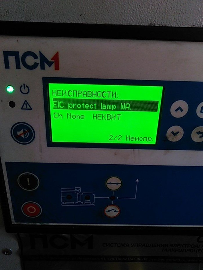
Неисправность ошибки аварийный останов на gc-1f
Неисправность ошибки аварийный останов на gc-1f
Сообщение Vladimir1983 » 01 сен 2020, 17:54

Неисправность ошибки аварийный останов на gc-1f
Сообщение Jackson » 01 сен 2020, 22:19
Квитирование аварии не означает её устранение.
1. В сам ПСМ обращались?
2. Проверить что цепь аварийного останова собрана.
3. Таймер ТО сбрасывается только с помощью сервисного ПО (оно бесплатно), если доступ к этому параметру не закрыт паролем, что могли сделать на заводе при настройке.
4. Если в настройках для таймера ТО задан класс аварии «аварийный стоп», то авария «аварийный стоп» так и будет активна до тех пор, пока не будет сброшен таймер ТО. Двигатель, соответственно, будет не запустить.
5. Заводские пароли есть в руководстве пользователя на контроллер, но ПСМ мог их изменить.
Неисправность ошибки аварийный останов на gc-1f
Сообщение Vladimir1983 » 02 сен 2020, 04:53
Неисправность ошибки аварийный останов на gc-1f
Сообщение Vladimir1983 » 02 сен 2020, 10:14
Неисправность ошибки аварийный останов на gc-1f
Сообщение Jackson » 02 сен 2020, 10:33
Нужен сервисный кабель (опция J9), приобретается в Российском представительстве.
Разъём там то ли RJ11 то ли RJ12, но физически там TTL и самодельными конверторами за $5 частенько жгут сервисный порт насовсем (один раз сожгли и USB в компьютере). Так что рекомендую фирменный кабель.
Либо, можете использовать любой (фирменный) конвертер RS-485/USB и подключаться не в сервисный порт, а на зажимы RS-485 ModBUS (если не ошибаюсь, это «49» и «51» — на тыльной стороне контроллера они обозначены). Тогда в сервисном ПО нужно выбрать (в настройках) подключение через COM-порт (не через сервисный), указать номер порта конвертера (посмотреть в диспетчере устройств, кнопка вызова диспетчера устройств есть тут же в настройках), скорость 9600 бод, slave-адрес по-умолчанию 3. Это если настройки ModBUS не были изменены с заводских (если были изменены, то придется перебирать адреса и скорости, лучше программой-сканером).
Если Вы купили у ПСМ именно контроллер, новый, то таймер ТО в нём не должен срабатывать — двигатель-то ещё не работал. Таймер считает либо когда двигатель работает, либо когда на контроллер подано питание (есть подробное описание. можно посмотреть). Для нового контроллера выглядит странно.
Не могли бы Вы прислать фото тыльной части контроллера целиком, чтобы все надписи было видно?
Источник
Прошу помощи
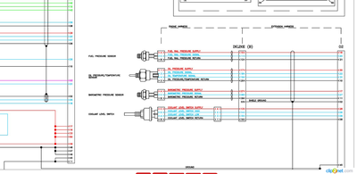
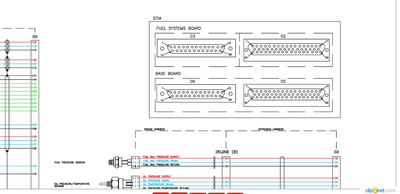
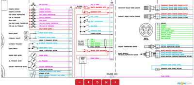
Ребята, может есть специалисты. Двигатель Cummins qsx15, работает через контроллер, выдаёт следующую ошибку и отключается,даже не запуская. не мог найти никакой информации, надеюсь, что кто то поможет разобраться в причинах
Дубликаты не найдены
В сервис ПСМ позвонить? Всегда помогают.
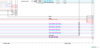
3490 Digital alarm input 20 (Emergency stop) похоже на залипший грибок экстренной остановки, на жопе контроллера 20 вход, там кстати есть усб
Часто все кнопки собраны последовательно и приходится проверять все.
Найди мануал на конкретный контроллер (Leroy-Somer) , ну или может тут что накопаешь (другая модель , описалово на английском):
херовый конечно, но хоть какой то мануал
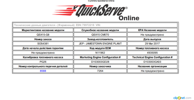
честно говоря я думал что под такой генератор руководству можно и купить диагностику в виде камминс инсайт с паролями на доступ к генераторам шоб не гадать что произошло.
а так- по номеру ESN могу тебе схему посмотреть этого генератора (электрическую) в принципе и оборудование для диагностики продать тоже ))))))
блин как коллеге я тебе конечно помогу со схемой на этот мотор и распиновкой. ESN только нужен и 8 цифр есн-на. По ошибке сорян конечно с такой панелью не сталкивался управления. я обычно ноут подоткнул и работаю с ними
3490- может быть банально разомкнут концевик. либо кнопка стопа. по самой установке критические ошибки с других цифр начинаются. что делали со станцией ?
я через программу -cummins insite работаю с такими моторами. ESN находится на блоке управления двигателем и на крышке клапанов есть табличка. на ней углы распредвала и прочая поебень и в том числе ESN
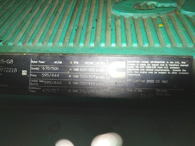
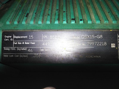
это паспортная табличка на всякий случай
херово тут в личку не на пишешь. так то бы проще было бы с помошью и советами
смотри- все ошибки по мотору (генератору) начинаются с 7-ки. так что искать надо в концевиках все таки проблему
как вариант конечно. сам в каком городе?
О в Вологде есть человек который поможет с каменсами. Андрюха- напротив ТЦ Рио. ремонт америки и европы.
да нормально все. самое главное номер мотора виден
Вы пробовали выключить это и снова включить?
Звони в техподдержку ПСМ, быстрее будет
а нажать на кнопку стоп, потом на кнопку с красным кружочком, после этого поглядеть, погаснет ли восклицательный знак, который мигает у вас, если нет, то еще что то не сквитировали, попробовать нажать ОК, вот тут посмотри мануалы, может найдешь ht.tps://www.deif.com/products/cgc-400#documentation (удалить точку в https)
там даже на русском есть мануалы, инструкция оператора нужна, как сквитировать и как зайти в журнал по ошибкам
Поискать коды ошибок по модели CGC 412
Рекомендую перевести контроллер на английский язык и прочитать код или описание ошибки на языке оригинала.
Часто бывает перевод некорректный.
А самое первое нажать и выдернуть красный грибок аварийного останова, и после этого сквитировать все ошибки.
Вторая похожа на ошибку датчика.
Мануал на контроллер есть?

Когда после 40 попросили паспорт на кассе


Навигация в мерсе

Так вот почему так долго ждёшь заказ)

Дежавю


Вопрос — Ответ

Девчонка спрашивает: «Взрослые парни, почему вы продолжаете играть в видеоигры?»
Парень отвечает: «По той же причине, почему вы носите мейкап, краситесь. Это отличный способ убежать от реальности.»

Блохер
В Москве поймали блогера, который был одет как полицейский.
Чудик надел полицейскую форму и даже взял игрушечный пистолет, что бы снимать тупые пранки.
Зеландия


А все потому что из Ривии

Словарный запас


Как сократить сроки ОРВИ

Просто выключу, я ни чего не видел.
Тема первого родительского собрания в этом году
Видеограф, фотограф,банкетный зал, ведущие, машины, залы, инстаграмм. 9 класс.

Ответ на пост «Дежавю»
Кстати, о малолетних троллях.
Когда сыну моих друзей исполнилось три, папа собрал ему шведскую стенку. Если ребенок по ней не лазал, он на ней висел. Даже спать пытался на антресолях, куда можно было попасть с верхних ступенек.
В пять Диму отдают в детский сад. В первый день мама приходит его забирать. Ей на встречу радостно выбегает вся группа и все кричат, что научили ее ребенка забираться на лесенку! Мама в недоумении отводит ребенка в сторону и интересуется, что это было? Оказалось, что на занятиях по физкультуре им велели лезть на шведскую стенку. Дима, отстаивая свое личное пространство, заявил что не умеет. И вот час вся группа, во главе с воспитателем объясняла Диме куда ставить ножку, где держаться ручкой. Эта личинка Люцифера за час ни разу не улыбнулась. Час изображал задержку развития, когда надоело — поднялся на три ступеньки.
Источник
Deif CGC 400: Manuals, Instructions
-
Johnson Controls
FEC26 Series
FEC26 Field Equipment Controllers Installation InstructionsMS-FEC2611-x, MS-FEC2621-x, MS-FEC2611-xETPart No. 24-10143-144, Rev. LIssued November 2017Refer to the QuickLIT website for the most up-to-date version of this document.ApplicationThe FEC26 controllers are part of the Metasys® systemField Equipment Controller (FEC) family. Thesecontrollers run pre-engineered and user-programmedapplicatio …
FEC26 Series Controller, 27
-
Leak
Gopher Series
Limited Warranty & Disclaimer Leak Intelligence, LLC will repair or replace, at its option, any part of the device, which proves to be defective in workmanship or material under normal use, in the USA except in the states of Alaska or Hawaii, for up to ten years from the date of purchase. This warranty does not include issues caused by the buildup of calcium or other chemicals in the valve or …
Gopher Series Controller, 2
-
Johnson Controls
METASYS VAV110
Application Specific Controllers Technical Manual 636.3 VAV Controller Section Technical Bulletin Issue Date 0309 © 2009 Johnson Controls, Inc. 1 Code No. LIT-6363040 Introduction Page 5 Description 5 OEM Applications 8 Standards Compliance *8 Coordination of Factory Mounted VAV Systems 8 Configuring the Controller 11 Using HVAC PRO for Wind …
METASYS VAV110 Controller, 92
-
RKC INSTRUMENT
CB103
®RKC INSTRUMENT INC.All Rights Reserved, Copyright © 1999, RKC INSTRUMENT INC. Digital Controller CB103/CB403/CB903 INSTRUCTION MANUAL IMCB11-E7 Thank you for purchasing this RKC product. In order to achieve maximum performance and ensure proper operation of your new instrument, carefully read all the instructions in this manual. Please place the manual in a convenient location for easy referenc …
CB103 Controller, 8