- Manuals
- Brands
- Delem Manuals
- Control Unit
- DA-66T
- Reference manual
Hide thumbs
Also See for DA-66T:
- Reference manual (190 pages)
1
2
Table Of Contents
3
4
5
6
7
8
9
10
11
12
13
14
15
16
17
18
19
20
21
22
23
24
25
26
27
28
29
30
31
32
33
34
35
36
37
38
39
40
41
42
43
44
45
46
47
48
49
50
51
52
53
54
55
56
57
58
59
60
61
62
63
64
65
66
67
68
69
70
71
72
73
74
75
76
77
78
79
80
81
82
83
84
85
86
87
88
89
90
91
92
93
94
95
96
97
98
99
100
101
102
103
104
105
106
107
108
109
110
111
112
113
114
115
116
117
118
119
120
121
122
123
124
125
126
127
128
129
130
131
132
133
134
135
136
137
138
139
140
141
142
143
144
145
146
147
148
149
150
151
152
153
154
155
156
157
158
159
160
161
162
163
164
165
166
167
168
169
170
171
172
173
174
175
176
177
178
179
180
181
182
183
184
185
186
187
188
189
190
191
192
193
194
195
196
197
198
199
200
201
202
203
204
205
206
207
208
209
210
211
212
213
214
215
216
217
218
-
page
of
218/
218 -
Contents
-
Table of Contents
-
Bookmarks
Table of Contents
Advertisement
7.2.8. Diagnostics
The diagnostics view mode is meant for service purpose mostly. In diagnostics the activities of
independent axes can be monitored. I/O on the control system can be followed. In rare
situations this information can be helpfull to diagnose operation during the bending proces.
V0913, 7.13
Table of Contents
Previous Page
Next Page
- 1
- …
- 118
- 119
- 120
- 121
Advertisement
Table of Contents
Related Manuals for Delem DA-66T
-

Controller Delem DA-66T Reference Manual
(190 pages)
-
Control Unit Delem DA-52s Installation Manual
Control on a pressbrake machine (73 pages)
Related Products for Delem DA-66T
- Delem DAC-310
- Delem DA-65W
- Delem DA-52s
- Delem DAC-360
- Delem DA-52
- Delem DA-56
- Delem DA-58T
- Delem DA-65
- Delem DA-69
- Delem DA-68PL
- Delem DA-40T Series
- Manuals
- Brands
- Delem Manuals
- Controller
- DA-66T
- Reference manual
-
Contents
-
Table of Contents
-
Bookmarks
Quick Links
DA-66T
Reference Manual
Operation of Version 1.1
English
8075-910A
Manual version V0311
Related Manuals for Delem DA-66T
Summary of Contents for Delem DA-66T
-
Page 1
DA-66T Reference Manual Operation of Version 1.1 English 8075-910A Manual version V0311… -
Page 2
Preface This manual describes the operation of the Delem controller type DA-66T and is meant for operators who are instructed for operation of the total machine. Delem Limited warranty • This manual does not entitle you to any rights. Delem reserves the right to change this manual without prior warning. -
Page 3: Table Of Contents
Table of contents 1. Operation overview and general introduction ….1.1 1.1. The control unit ……….. . 1.1 1.2.
-
Page 4
Notes: …………3.9 3.4. -
Page 5
Cancel …………5.8 Accept . -
Page 6
8. Manual mode ……….8.1 8.1. -
Page 7
Graphical directory dies ……… 10.17 10.3.2. -
Page 8
V0311, VIII… -
Page 9: Operation Overview And General Introduction
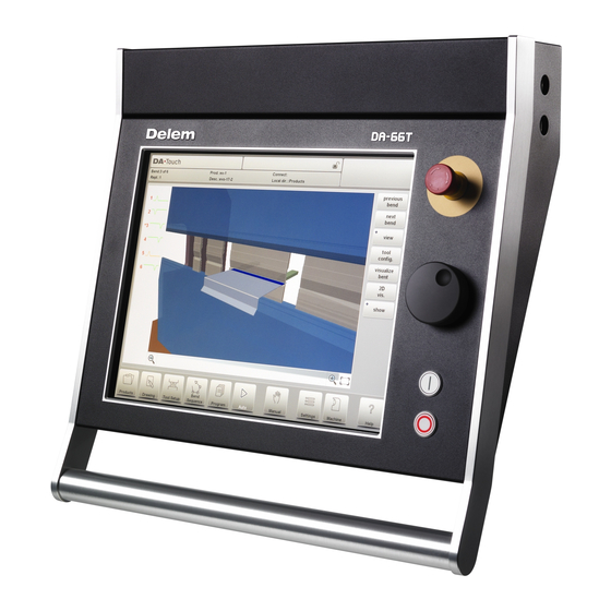
Operation overview and general introduction 1.1. The control unit The control looks as follows: The precise outfit of your control may vary. Operation of the control is mainly done over the touchscreen. A description of the functions and available touch controls is given in the next sections of this manual, aside of the description of the specific functions.
-
Page 10: Front Control Elements
1.2. Front control elements The frontpanel, beside display, consists of the following control elements: Emergency stop button, to be implemented by machine manufacturer. Handwheel; manual control of any axis (Y + backgauge axes) Start button Stop button 1.3. USB connectors At the right side of the control two USB ports are available for connection of external devices, such as memory sticks or an external keyboard / mouse.
-
Page 11: Operation And Programming Modes
1.4. Operation and programming modes The DA-Touch control’s main screen looks as follows: Depending on the navigation button which is active, the screen will differ. The above main screen will appear having the Products function active. Just by tapping the various modes, the specific mode will be selected. The structure of the main screen is as follows: Title panel In the top the title panel is always shown.
-
Page 12: Information Panel
Information panel In the information panel all functions and visualisation related to the selected modus are displayed and can be found. Command panel The command panel is part of the Information panel and is the location where the controls related to the Information panel can be found. Navigation panel The Navigation panel is the area where all the major modes can be found.
-
Page 13
Explanation of the main modes / navigation buttons To make a new program and select a program out of the product library. To draw/create a new product or edit an existing product (graphically). To setup the machine and modify existing tool setups. To compute and modify the bend sequence. -
Page 14: Getting Started
1.5. Getting started 1.5.1. Introduction In order to obtain a bend program for a product, the control offers the possibility to create a product drawing and calculate a valid bend sequence for the product. With this information, a product program is generated. This is done with the following steps: Go to the Products mode in the navigation panel and start a new product by tap- ping New Product.
-
Page 15: Value Setting
Value Setting Once the product or tool is drawn in the Sketching method the exact values of line lengths and angles can be optimized by the Value setting method. Just tap 2 times on the value of the line length or angle to change and the keyboard will pop-up. The value can be entered in 2 ways of confirmation: •…
-
Page 16: Determine Bend Sequence
1.5.4. Determine bend sequence When the product drawing is completed, the control offers Tool setup mode to program the exact tool set-up as it is organised on the machine. After this you can select the Bend Sequence mode to determine and simulate the required bend sequence. In the Bend Sequence mode, the control shows the product, the machine and the tools.
-
Page 17: The Auto Menu And Manual Menu, Production Modes
Both product and tool files can be stored externally. Depending on the configuration, these files can be stored on a network or on a USB storage device. This facilitates a back-up of important data and the possibility to exchange files between Delem controls. More information about this can be found in chapter 7.
-
Page 18: Programming Aids
1.6. Programming aids 1.6.1. Help text This control is equipped with an on-line Help function. When the Help-button in the navigation panel is pressed context sensitive help will be provided. To activate a help window for a parameter tap the Help button in the navigation panel. A pop-up window appears with information on the active parameter.
-
Page 19: Listbox Functionality
1.6.2. Listbox functionality Several parameters on the control have a limited number of possible values. When selecting such a parameter, by tapping the parameter line on the screen, the list of options will open up near the position where you tapped the line, and the desired value can be selected. To undo the selection and the opened listbox, tapping outside the box will make it close without changing the selected parameter.
-
Page 20: Navigation
1.6.4. Navigation Within some modes, the program screens are divided into tabs. The tabs can easily be selected by just tapping them. When a tab is not completely visible or not visible at all, just by dragging the tab row horizontally, the desired tab can be «pulled» in sight and be selected.
-
Page 21: Typing Alphanumeric Characters Vs. Special Characters
1.6.5. Typing alphanumeric characters vs. special characters Both alphanumeric characters and special characters can be used throughout the control. A full on-screen alphanumerical keyboard will pop up when required. When editing a field which is pure numeric, the alphanumeric characters will be «greyed-out» and only the numerical keypad can be used.
-
Page 22: Network
1.6.6. Network The CNC control is equipped with a network interface. The network function offers the operators the possibility to import product files directly from the network directories or to export the finished product files to the required network directory. Chapter 9 about Settings mode contains more information about networking possibilities.
-
Page 23: Keylock Function
1.6.7. Keylock function To prevent for changes to products or programs, the keylock function offers the possibility to lock the control. In the locked state, only a product can be selected and executed in Auto mode. To lock a control just tap the lock symbol in the top of the screen. Lock symbols will also appear behind parameters to show the lock is active and modification is not possible.
-
Page 24
Codes can be changed upon desire. The procedure to manages codes can be found in the Installation manual. V0311, 1.16… -
Page 25: Software Versions
1.6.8. Software versions The version of the software in your control is displayed at the last tab in the Machine menu. Example of version number: V 1.2.3 V stands for version V 1.x.x is the major version number V x.2.x is the minor version number V x.x.3 is the update version number The major version number is increased when new major features are added to the software.
-
Page 26
V0311, 1.18… -
Page 27: Products, The Product Library
Products, the product library 2.1. Introduction In the Products mode existing, previously produced, products can be selected to start production or for modification in order to make a similar product. To start making a new product or program New Product or New Program can be used from this mode. 2.1.1.
-
Page 28: Product Selection
the product has a CNC program, there is no drawing the product consists of a 2D drawing, there is no CNC program the product has a 2D drawing and a CNC program the product consists of a 3D drawing, there is no CNC program the product has a 3D drawing and a CNC program If a product program is already active its ID is shown in the top of the screen.
-
Page 29: New Product, Starting A New Graphical Product
2.1.3. New Product, starting a new graphical product To start a new graphical product tap New Product. After New Product is chosen, the programming of a new product starts with its general details like Product ID, Thickness and Material. V0311, 2.3…
-
Page 30: New Program, Starting A Numerical Program
2.1.4. New Program, starting a numerical program To start a new numerical program tap New Program. After New Program is chosen, the programming starts with its general details like e.g. Product ID, Thickness and Material. The shown general tab is next to the successive tabs which are ready for programming the first bend.
-
Page 31: Views
2.1.5. Views To view the products as a simple list, or completely graphical the View function can be used. By tapping View one of the three view modes can be selected. V0311, 2.5…
-
Page 32
V0311, 2.6… -
Page 33: Edit, Copying And Deleting A Product Or Program
2.1.6. Edit, Copying and Deleting a product or program To delete a product in the Products mode select a product by tapping it. It will be selected. After that tap Edit and use Delete. To finally delete it confirm the question. To delete all products and programs at ones, tap Delete All.
-
Page 34: Filter Function
2.1.7. Filter function To make finding products easier the filter function enables live searches through-out the Products mode. When tapping Filter, the filter screen will show. By typing the desired filter string, optionally devided by spaces, the live search will start. Optionally a different view can be selected.
-
Page 35: Change Directory
Tap Make Subdir and enter the new name. Subdirectories are called subdirectories because these directories reside under the local directory ‘DELEMPRODUCTS’. The name of the subdirectory cannot be changed. In this menu it is not possible to copy products from one subdirectory to another subdirectory;…
-
Page 36
V0311, 2.10… -
Page 37: Product Drawing
Product drawing 3.1. General product properties To edit an existing product drawing, choose the specific product from the Product library and select Drawing. To start a new product drawing, choose New Product in the product library When a new product drawing is started a screen with general product properties appears. First these properties, general data, should be set before starting with the product drawing.
-
Page 38
Product ID A unique name to identify a product program. The maximum length is 25 characters. The product ID may contain letters and numbers as available on the keyboard. Product description A name or description of this program. The maximum length is 25 characters. The product description may contain letters and numbers. -
Page 39
To change the active directory select Change Directory. The current product is automatically copied to the new directory When Edit Notes has been pressed, a new window appears in which you can edit the text about the current product. The possible characters are displayed on the keyboard. V0311, 3.3… -
Page 40
V0311, 3.4… -
Page 41: Product Drawing
3.2. 2D product drawing 3.2.1. Introduction After entering the general product data the drawing screen appears. In the upper information row you will find the information about product ID, product description, inside/outside dimensions selection and actual product directory. Now you can create the profile of the product. It is possible by using your fingers to tap and create quickly the product in ‘sketch’ mode.
-
Page 42
The currently active element (line or angle) is highlighted. In a product drawing you can program up to a maximum of 99 bends per product (graphical programming). When the product drawing is finished it is possible to navigate to the next step in the programming process;… -
Page 43: Line Properties
3.3. Line properties 3.3.1. Introduction When the cursor is on one of the product lines it is possible to change the properties of that line by selecting Properties. 3.3.2. Projection Inside the window with line properties, the following projection properties can be programmed: Horizontal projection The horizontal distance a line must measure, regardless of its angle value.
-
Page 44: Precision Selection
or vertical projection distance and press Enter. The required line length is computed and applied to the selected segment. is normal entered line length is vertical projected line length is horizontal projected line length It will be noted on the screen if projection is not possible. 3.3.3.
-
Page 45: Notes
Line interval marked with the open circle should be, if possible, directly placed between back stop and the centre of the die. Notes: Specifying line intervals with high precision and closing dimensions may result in longer production time. The precision parameter will have priority over the «front extend ratio», if that is set to «comply if possible».
-
Page 46: Bend Properties
3.4. Bend properties 3.4.1. Air bend Drawing a product graphically is simply programming the line length, angle value, next line length, etc. till the product has its required shape. The bends in the product have their standard or specific properties. The bend properties can be set by putting the cursor on the bend and selecting Properties.
-
Page 47
Computed radius The resulting radius as computed from the control settings. Amongst others the resulting radius is depending on the used tools in the bending process A large radius is meant to be bent with a special radius punch with large radius. If such a punch is not available, the bumping method can be selected. -
Page 48: Large Radius: Bumping
3.4.2. Large radius: Bumping If a tool with large radius is not available, the bumping method can be chosen. With this method, a large radius in a product is obtained by a series of slight bends in succession. First you can choose the Angle Definition. The available definitions are: The default angle is the angle which could be programmed as standard.
-
Page 49
To apply the bumping method, the following parameters must be programmed: Central angle The supplement of the angle value to bend. Number of segments The number of segments in which the radius will be divided. The number of bends in this radius is the number of segments plus 1. -
Page 50: Hem Bends
3.4.3. Hem bends When creating the required profile of the product with a hem bend it is possible to first prepare a flange with a prebend angle, place the cursor on the bend and select Properties. The bend properties can be programmed in the pop-up window. It is also possible to create a hem bend by placing the cursor on the flange end where the hem bend is required and select properties.
-
Page 51: Side Properties
Side properties Side length The length of the flange to hem. V0311, 3.15…
-
Page 52
V0311, 3.16… -
Page 53: Tool Configuration
Tool configuration 4.1. Introduction To edit or modify a tool setup for the product, select the product from the library and use Tool Setup 4.2. Standard procedure When the function Tool Setup has been activated, the screen shows a front view of the machine set-up in the upper half of the screen.
-
Page 54: Tool Selection
4.3. Tool selection When starting a new tool configuration, the machine opening is empty. Select Add to add a tool to the configuration; punch, die or adapter (if enabled). When a tool has been chosen (e.g. a punch), it is placed in the machine with maximum available length.
-
Page 55
After a tool is placed, the tool ID can be changed by typing an ID, by pressing the Punch ID in the screen and tapping on the List view. If only a part of the tool ID is typed, the control automatically offers a list of tools with the typed characters. -
Page 56
To change length and position of a tool, move the cursor to the appropriate field, type a new value and press ENTER. When the length and position are changed, the tool is ready. After the punch is finished, a die with the default ID, with the same length and position as the prepared punch is put below the punch. -
Page 57
Delete config. The existing configuration is deleted and a new tool configuration can be started. Add a new tool to the tool configuration. When pressed, some new functions are offered to choose the tool: punch, die or adapter (if enabled). Assignm. -
Page 58: Assignments
4.4. Assignments 4.4.1. Introduction The Assignments are parameters with which the bend sequence computation is controlled. The assignments screen is opened from the tool configuration screen with the function key Assignm. Automatic bend sequence computation works with several conditions in order to find an optimum between a minimum production time, handling possibilities without product/machine and product/tool collision.
-
Page 59: Cancel
Cancel Leave the current screen without saving changes. Accept Save the changes and leave the current screen. 4.4.2. Assignments — general Optimisation degree Range 1-5. The number of alternatives to be computed for each bend must be entered here. The higher this number the more alternatives are to be examined by the control, so the longer the computing time will be.
-
Page 60
Punch length tolerance The punch length may be shorter than the length of the bendline. The maximum allowed difference between the punch length and bend length can be programmed here. Punch length tolerance may influence your bend sequence: if the length of a punch is shorter than the tolerance permits, it will not be accepted for a bend. -
Page 61: Assignments — Backgauge Possibilities
4.4.3. Assignments — Backgauge possibilities Backstop against sharp angle allowed Specify if backstop may be placed against an angle smaller than 90°. No = not allowed Yes = allowed V0311, 4.9…
-
Page 62
Backstop-die, intermediate bend Set to allow if there may be a bend between the die and backstop. Selection possibilities: Permitted If unavoidable permitted: if it results that no solutions are to be found, than it is permitted Prohibited: never allowed. Edge tolerance In case backstop is against flat sheet an angle tolerance is allowed (deviation from horizontal). -
Page 63
Lay-on backstop limit This parameter is useful in case the press brake has been equipped with backgauge fingers on a moving R-axis, having a so-called «lay-on» construction. When the length of the sheet at the backside of the machine is greater than this limit, the X-axis and R-axis positions will be corrected automatically so the sheet will rest on the backgauge finger. -
Page 64
V0311, 4.12… -
Page 65: Bend Sequence
Bend sequence 5.1. Introduction To generate or modify a bend sequence for the product drawing, select the product from the library and use Bend Sequence When a tool configuration is available, the bend simulation can be started to determine a bend sequence for the active product.
-
Page 66: Functions
Functions: Unbend Unbend the currently shown bend or start searching for the next feasible bend to unfold. Bend Bend the product in the simulation screen or switch to the next bend step. Shift product / Shift gauge Shift the product manually (if product is bent) or shift the gauge manually (if product is unbent).
-
Page 67: View
View Button to select a possible viewing mode: — 2D visualization — 3D visualization — reset the view to the initial view of the product in the machine Show Toggle between some possible ways of displaying the product/tool configuration: — product — product/tools — all Show Bendsequence…
-
Page 68: Unbend Product
5.1.1. Unbend product In order to generate a CNC-program the bend sequence must be known. There are two ways to achieve this: • Press the function key Compute. The control will automatically compute the quickest possible bend sequence for this product. •…
-
Page 69: Functions
Functions: Shift Front Shift the product to the front. Shift Back Shift the product to the back. Change Orientation Turn the product 90 degrees. Only possible for a 3D product in the 3D controller type. Swap Turn the product between the tools (back to front). Cancel Leave the current screen without saving changes.
-
Page 70: Jump Left
Jump Left Move the product to another toolset combination in the left direction. Jump Right Move the product to another toolset combination in the right direction. Shift Left Shift product to the left within the same toolset. The step size is displayed at the command line prompt and can be changed.
-
Page 71: Move Gauge
5.1.4. Move gauge The control automatically computes at each bend the X axes, R axes and Z axes positions. It takes into account the values of the option assignments and searches for a solution without collision of the fingers with the product. In order to be able to choose alternative positions, you can move the fingers manually.
-
Page 72: Shift Left
Shift Left Shift the selected finger to the left. The step size is displayed at the command line prompt and can be changed. Shift Right Shift the selected finger to the right. The step size is displayed at the command line prompt and can be changed.
-
Page 73: Show Bend Sequence
5.1.5. Show bend sequence When the function Show Bend Sequence has been pressed, a graphical overview of the bend sequence is shown. This option can be called at any time after the first unbend has been made. The graphical overview displays the determined bends as well as the not yet determined bends (question mark sign).
-
Page 74: New
Functions: Start a new bend sequence, any existing sequence is removed. This is for automatic computed bend sequences. New Flat Start a new bend sequence from a flat sheet. This is for manual determined bend sequences. Restore Restore an existing bend sequence from disk, but disregard any related CNC program. Re-use Restore an existing bend sequence from disk, including the related CNC program.
-
Page 75: Product Programming
Product programming 6.1. Introduction To generate or modify a numerical program, start a new program from the Products mode or use Program to enter directly To edit an existing CNC program, select a product in the Products overview and select the navigation button Program.
-
Page 76: Functions
The general page gives all data which are the same for every bending of the program (main data of program). Functions Copy Copy the current product. When pressed, you must enter a new product ID for the copy program. First Bend The cursor jumps to the page with the first bend information.
-
Page 77: Edit Notes
Edit notes It is possible to add a note to your product, in order to store comment or background information about the current product. The note is a simple text field, it has no influence on product values or bend sequence calculations.
-
Page 78
Thickness Thickness of the sheet. Material Selection of one of the programmed materials, which are used to calculate the bending depths. The control contains 6 pre-programmed materials. In total, 99 materials can be programmed on the control. See the chapter about programming constants how to program materials. -
Page 79
There are now two bend programs of one product in two directions. You connect these programs as follows: Select the program with the bend sequence in the direction which you want to execute in the first place. You select the program of the product via the ’product library’. -
Page 80: Bend Parameters — Basic Data
6.2. Bend parameters — basic data The parameters of one bend are divided over several pages. The bend number, product ID and product description are displayed in the top row on the screen. Functions Turn Punch / Turn Die Turn around the applied tool (back to front). Only available if the cursor is placed on a tool parameter.
-
Page 81: Note 1
Method Select the required bending method. The control supports 4 methods: • air bend • bottoming • hemming • hemming & bottoming Bend methods: air bend The sheet is bent to the programmed angle by bringing the punch to the required depth. The control calculates the required Y-axis position to obtain the programmed angle.
-
Page 82
Bending length Length of the sheet between tools. Angle The required angle of this bend. This parameter only appears if angle programming is selected with the parameter ‘Angle sel.’ and the bend method is an air bend. Hem opening The hem bend can be made with a certain opening distance between the 2 flanges. The hem opening value will be used calculating the beam position in the hemming process. -
Page 83: Gauge Function
Gauge function The function key Gauge Func’ appears when the cursor bar is on an axis parameter. If Gauge Func is pressed, a window appears with several programmable parameters. These parameters serve to program the desired finger positions for a certain bend. The necessary axis positions that are necessary for this bend are calculated from the programmed finger positions V0311, 6.9…
-
Page 84
The value in X-direction of the finger position for the sheet. This value can manually be adjusted in this window, if required. The height (R-direction) of the gauge position of the sheet. This value can manually be adjusted in this window, if required. Lay-on With this parameter you can program another finger position for this specific bend. -
Page 85: Bend-Parameters Optional Data
6.3. Bend-Parameters Optional data Auxiliary functions of the bending can be programmed on this page. Mute Sequence point at which the Y-axis is switched from fast closing speed to pressing speed. The value programmed here is the distance of the mute point above the sheet. By default, the mute value from the programmed die is used.
-
Page 86
Wait for retract In case of a retract, let the Y-axis wait until the retract is finished, yes or no. No: the retract is started when the Y-axis passes the clamping point, the Y-axis does not stop. Yes: when the Y-axis reaches the clamping point, the Y-axis is stopped and the retract is started. -
Page 87: Bend Parameters — Auxiliary Axes
Bend parameters — auxiliary axes On this page, if available, more additional programmable axes are shown. The axes shown here depend on the machine configuration. Note: After selecting a new bend this will be a copy of the preceding one; you only have to alter those parameters which are different from the preceding bend.
-
Page 88: Bend Parameters — All Bends
Bend parameters — all bends When the function All Bends has been pressed, a complete overview of the bends appears. After pushing End the page from which this page was selected will be restored, with the cursor on the parameter selected before. Specific bend can be selected on the screen by putting the highlighted bar on that bend, then pressing END.
-
Page 89: Insert Bend
When the function Edit has been pressed a new, temporary button bar appears with additional functions: Insert Bend To insert a new bend between one of the bends. When pressed, the current bend is copied and added after the current bend. Mark Bend Mark the current bend, in order to prepare it for another action, like move or swap.
-
Page 90: Special Edit Remarks
6.4. Special edit remarks After changing program data the control will not automatically calculate: Force Decompression Crowning device setting Z-axis position offset X-axis position correction Parameters 1 through 4 are only automatically recalculated if the parameter Auto Computations Edit (see Settings) has been enabled. Parameter 5 is only automatically recalculated if the parameter Bend Allowance (see Settings) has been activated.
-
Page 91: Automatic / Step By Step Mode
Automatic / step by step mode 7.1. Introduction By tapping the navigation button Auto the control is switched to the automatic production mode. In auto mode with the active program, production can be started. After entering Auto, the Start button can be pressed and production can begin. The automatic mode executes the program automatically bend by bend after pushing the Start button.
-
Page 92: Auto Mode, Parameter Explanation
7.1.1. Auto mode, parameter explanation Following is a list of the available parameters in Auto mode. Bend no. Selection of a bend of the active program. Repetition Selection of one of the repeated steps of one bend. Useful if a bend has a repetition value larger than 1.
-
Page 93
saved in the active bending program. The X-axis correction should be entered as following examples indicate: Programmed value of 200 millimetres. Measured value of 202 millimetres. -> Then it is required to program Corr.x with -2. Programmed value of 200 millimetres. Measured value of 198 millimetres. -
Page 94: View
7.2. View To view specific functions or states View gives access to special screens. The functions screen, correction screen, zoomed values, graphical visualisation can be switched to. By tapping View the available view modes can be selected. The default view is Axes in which the major axes are shown.
-
Page 95: Angle Corrections
7.2.2. Angle corrections Angle corrections can be edited in a separate window. This window can be activated by tapping Alpha Corr. The following window appears: In this window the corrections of all bends are shown. You can browse through all corrections and change them as you see fit.
-
Page 96: Corrections
7.2.3. X corrections X-axis corrections can be edited in the main screen. When there are multiple axis available a separate window can be switched to for axes corrections. This window can be activated with X Corr. in the main screen. The following window appears: V0311, 7.6…
-
Page 97: Graphical Visualisation
7.2.4. Graphical visualisation Switch to graphical visualization to see the product in its current bend state, shown with or without machine / tooling. Optionally the view can be switched to 3D, by 3D Vis., to have the product and machine shown in 3D.
-
Page 98: Zoomed Values
7.2.5. Zoomed values With Zoomed Values, the control switches to a new view with only large axes values on the screen. This view can be used when working a little remote from the control, still able to read the axes values. 7.2.6.
-
Page 99: Notes
7.2.7. Notes The notes which can be added to a product or program can be viewed in Auto mode. With the presence of Notes the indication is given that notes are added to this product and by tapping Notes these will be shown. Notes can be added generally to a product or program but also to specific bends.
-
Page 100: Tool Configuration
7.3. Tool Configuration Tool Config. shows the tool configuration which is required for the selected bend. In the tool configuration pop-up also tool properties, next to their required position, can be checked. V0311, 7.10…
-
Page 101: Bumping Correction
7.4. Bumping correction With this function a general correction for a radius bend can be entered. This function can be activated when the cursor is on the parameter for angle correction (‘corr. 1/ 2’). It is only available if a product is loaded that contains a radius bend. With Bumping Corr.
-
Page 102
V0311, 7.12… -
Page 103: Manual Mode
Manual mode 8.1. Introduction By tapping the navigation button Manual the control is switched to the manual production mode. In manual mode you program the parameters for one bending. This mode is useful for testing, for calibration and for single bends. Manual mode is independent from Automatic mode and can be programmed independently of the programs in memory.
-
Page 104: Manual Mode, Parameter Explanation
8.1.1. Manual mode, parameter explanation Punch The name (ID) of the applied punch. Tap to modify or select from the punch library. The name (ID) of the applied die. Tap to modify or select from the die library. The tool selection enables you to directly type the desired tool, or by tapping the list key on the keyboard, the library will be shown and a selection can be made.
-
Page 105
Material Selection of one of the programmed materials, which are used to calculate the bending depths. The control contains 4 pre-programmed materials. In total, 99 materials can be programmed on the control. See the chapter about Settings mode, Materials, how to program materials. -
Page 106
Corr.Y Correction on the Y-axis position, in case bottoming has been selected. Angle Angle to bend. Hem opening The hem bend can be made with a certain opening distance between the 2 flanges. The hem opening value will be used calculating the beam position in the hemming process. The parameter will prompt with a default value as programmed in the ’program constants’… -
Page 107
Auxiliary axis If you have one or more auxiliary axes (for instance a R-axis, Z-axis or part support) the parameters of these axes appear here. When you have a R1-axis and a R2 axis the programmed R1 value is automatically copied to the R2-axis value. The R2-axis value can, if necessary, be changed afterwards. -
Page 108: View
PS return speed Return speed of the part support after a bending. The speed value is programmed as a percentage of the maximum speed. (Only available if a part support is present.) The above mentioned parameters can be programmed and modified as required. After pushing the Start button the programmed parameters are active.
-
Page 109: Zoom Function
8.2.1. Zoom function With Zoomed Values, the control switches to a new view with only large axes values on the screen. This view can be used when working a little remote from the control, still able to read the axes values. V0311, 8.7…
-
Page 110: Axis State
8.2.2. Axis state When tapping Axis State, the control switches to a new view with axes states. In this window, the current state of available axes can be observed. This screen can also be active while the control is started. As such, it can be used to monitor the control behaviour during a bend cycle.
-
Page 111: Io Status
8.2.3. IO status When tapping IO Status, the control switches to a new view with the state of inputs and outputs. In this window, the current state of inputs and outputs can be observed. This screen can also be active while the control is started. As such, it can be used to monitor the control behaviour during a bend cycle.
-
Page 112: Manual Movement Of The Axes
8.3. Manual movement of the axes 8.3.1. Movement procedure To move an axis to a specific position manually, the hand wheel on the front panel of the control can be used. After tapping Manual Pos in the main screen of Manual Mode, the following screen appears: Within this mode, any of the shown axes can be moved by turning the hand wheel.
-
Page 113: Teach
8.3.2. Teach To teach the control, taking over a position found by manual moving an axis, a simple procedure can be used. When you have moved an axis to a certain position with the hand wheel, you may want to store this position.
-
Page 114
V0311, 8.12… -
Page 115: Settings
Settings 9.1. Introduction By tapping the navigation button Settings the control is switched to settings mode. The Settings mode of the control, which can be found in the navigation panel, gives access to all kind of settings which influence the programming of new products and programs. Default values and specific constraints can be set.
-
Page 116: General
9.2. General Select the required tab and tap the parameter to be changed. When parameters have a numerical or alphanumerical value, the keyboard will appear to enter the desired value. When the setting or parameter can be selected from a list, the list will appear and selection can be done by tapping.
-
Page 117
Key sound Switch the sound function of the input panel on or off. Default sound is on. V0311, 9.3… -
Page 118: Materials
9.3. Materials In this tab, materials with their properties can be programmed. Existing materials can be edited, new materials can be added or existing materials deleted. A maximum of 99 materials can be programmed on the control. For each material, three properties are present and can be viewed and edited. Material name Name of the material, as it will appear in the programming screens.
-
Page 119: Backup / Restore
9.4. Backup / restore This tab offers the possibilities to backup and restore products as well as tools. Tools and products can be backupped and restored according to the following procedures. The procedures for saving or reading data are similar for all types of backup media: e.g. network or USB disk.
-
Page 120
V0311, 9.6… -
Page 121: Product Backup
9.4.1. Product backup To make a backup of programs to disk, choose Backup in the main menu for Products. When the initial backup directory has been set, the products backup screen appears. In the backup screen the products in the selected directory are shown. Basic functions to change the view can be chosen similarly to the Products mode.
-
Page 122: Product Restore
9.4.2. Product restore To make a restore programs to the control, choose Restore in the main menu for Products. When the initial restore directory has been set, the products restore screen appears. In the restore screen the products in the selected directory are shown. Basic functions to change the view can be chosen similarly to the Products mode.
-
Page 123: Tool Backup
9.4.3. Tool backup To make a backup of tools to disk, choose Backup in the main menu for Tools. When the initial backup directory has been set, the tools backup screen appears. With this menu a back-up of tools on the control can be made: punches, dies or machine shapes.
-
Page 124: Directory Navigation
9.4.5. Directory navigation When Backup Directory is used, a new window appears with a list of available backup directories. In this window you can browse through the directory structure of your backup device. Tap the dot to look inside a subdirectory. To move one level up, tap the (PARENT) map. To select the directory you are currently in, tap Select.
-
Page 125: Program Settings
9.5. Program settings Angle correction computation Parameter to enable the input of ‘measured angles’ for which corrections will be calculated. disabled no correction computation from measured angles. enabled => the operator can enter the measured angle of a bend and haveangle corrections calculated.
-
Page 126
When searching for similar bends, the control searches for bends that have the same properties as the active bend. The following properties of a bend are compared: • Material properties • Thickness • Die opening • Die radius • Punch radius •… -
Page 127
If the Automatic computations edit is switched off (default situation) then these parameters stay the same. However, when you enter these parameters by tapping them the recomputed value is displayed. When you press ‘enter’ the recomputed value replaces the old value after all. So, you can choose to change the values. X1X2 difference programming Parameter to select in between angle programming or offset programming for the X- axes backgauge. -
Page 128
Default dwell time Default value for the parameter ‘dwell time’ in a bend program. Default hem opening The hem bend can be made with a certain opening distance between the 2 flanges. The hem opening value will be used calculating the beam position in the hemming process. This programmed default value will be used when programming the product with hem bend graphically in the Drawing mode or by programming a new program in the Program mode. -
Page 129: Computation Settings
9.6. Computation settings Active bend allowance table computation=> the control will calculate the bend alowance table =>the bend allowance table will be used Bend-allowance is the correction of the X-axis due to sheet shortening after bending. With this parameter the method for bend-allowance calculation is chosen. ‘Computation’ means the standard formula of the control is used to calculate the bend-allowance.
-
Page 130
It is not possible to create a table through this menu. Only when a table has been loaded into the control is it possible to edit its contents. For more information about bend-allowance tables, we refer to the Delem manual of the bend- allowance table. -
Page 131: Production Settings
9.7. Production settings Stock count mode Setting for the stock counter in production mode, to have the stock counter (product counter) count up or down. When down counting is selected, the stock counter in production mode is decremented after each product cycle. When the counter has reached zero, the control is stopped. On the next start action, the stock counting value is reset to its original value.
-
Page 132
Parallelism offset An overall parallelism, valid for the complete Y-axis stroke, can be programmed with this parameter. The programmed value will be checked against the maximum allowed value during production. The parallelism which can be programmed for each bending (Y2) is only active below the clamping point. -
Page 133
When the back gauge has to move to a different Z-position, it is checked whether the current X-position is safe. We can distinguish the following situations: • Old X-axis position as well as new position outside the zone: X- and Z-axis movements happen at the same time, no change. -
Page 134: Production Time Calculation
9.8. Production time calculation The parameters on this page are used to calculate the production time for a product in the bend sequence computation process . This production time depends on the positioning speed of the axes and the product handling times. Closing speed Speed of the Y axis during fast closing.
-
Page 135: Machine
Machine 10.1. Introduction By tapping the navigation button Machine the control is switched to Machine mode. The Machine mode of the control, which can be found in the navigation panel, gives access to the configuration items of the machine and specific machine characteristics which influence generic calculations and machine behaviour.
-
Page 136: Programming Of Punches
10.2. Programming of Punches In this tab, the punches used in the machine, can be programmed. New punches can be added, existing punches can be edited and also deleted. 10.2.1. View In the main page, a list of available punches is shown. By using the View function, similar to Products mode, different views can be selected.
-
Page 137: Graphical Directory
Graphical directory In Graphical the geometry of the tools is shown as well as the main properties. In Graphical Heel specifically the programmed heel properties. V0311, 10.3…
-
Page 138: Create A New Punch
10.2.2. Create a new punch To create a new punch, tap Edit in the library and subsequently use New. The punch profile can be created with help of the programming and drawing facilities of the control. First the basic shape of the punch and its ID must be programmed. After that the shape details must be programmed following the wizard under Basic Data and Optional Data, the tool drawing is started.
-
Page 139: Standard Punch
10.2.3. Standard punch Standard punch, Basic data Height The height the tool. Important: this height value will be used in the bend depth calculation. Angle The angle of the punch tip. Radius The radius of the punch tip. This value will be used as inner radius of the bend to make when this radius value is bigger than the inner radius as will result from the bending process.
-
Page 140: Standard Punch, Optional Data
Standard punch, Optional data Description A name or description of this tool. The maximum length is 25 characters. This description has already been entered in the beginning defining the tool, but can be edited in this field. The description is listed in the tool overview of the library. Resistance Maximum allowable force on the tool.
-
Page 141: Heel Dimensions
If ‘shoulder mounted’ is chosen, the Y-axis position is calculated from the standard tool height. This is the default setting. If ‘head mounted’ is chosen, a correction is made for Y-axis computation Heel dimensions Width Width of the heel. Height 1 Height1 of the heel.
-
Page 142: Drawing
Drawing After entering these typical values you can create the tool drawing with the drawing facilities. Drawing a tool profile is done by entering angle values and line length values. Also the Touch drawing tools are available as with the product drawing method. Following functions are available while drawing Delete Line To delete a line segment.
-
Page 143: Edit Punch Drawing
Edit punch drawing To edit an existing tool, tap the tool in the library. The tool appears on the screen and can be edited with the drawing facilities. Drawing orientation of the punch on the screen The right hand side of the tool is the back gauge side. The bottom point of the punch will be placed on the center line of the press brake shape.
-
Page 144: Hem Bend Punch
10.2.4. Hem bend punch Hem bend punch, basic data Height The total height of the tool. Important: this height value will be used in the bend depth calculation. Hemming width The width of the tool to program. Hemming load openin Depending on the construction of your machine you can program here an opening position for your punch at which position you can put in your product to hem the particular bend.
-
Page 145: Air + Hem Bend Punch
10.2.5. Air + hem bend punch Air + hem bend punch, basic data Height The total height of the tool. Important: this height value will be used in the bend depth calculation. Angle The angle of the punch tip. Radius The radius of the punch tip.
-
Page 146
Hemming load opening Depending on the construction of your machine you can program here an opening position for your punch at which position you can put in your product to hem the particular bend. The opening position will also take twice the sheet thickness into account. -
Page 147: Air + Hem Bend Punch, Optional Data
Air + hem bend punch, optional data Hemming resistance Maximum allowable force on the tool during hemming. After entering these typical values you can create the tool drawing with the drawing facilities. Drawing a tool profile is done by entering angle values and line length values. These values are prompted in the lower left corner of the screen.
-
Page 148: Big Radius Punch
10.2.6. Big radius punch Big radius punch, basic data Height The total height of the tool. Important: this height value will be used in the bend depth calculation. Radius The radius of the punch tip. Radius height The height of the big radius part of the special tool as indicated in the drawing on the screen for the basic data.
-
Page 149
V0311, 10.15… -
Page 150: Programming Of Bottom Dies
10.3. Programming of bottom dies In this tab, the bottom dies used in the machine, can be programmed. New dies can be added, existing dies can be edited and also deleted. 10.3.1. View In the main page, a list of available dies is shown. By using the View function, similar to Products mode, different views can be selected.
-
Page 151: Graphical Directory Dies
Graphical directory dies In Graphical the geometry of the dies is shown as well as the main properties. To program a new die, tap Edit in the library and subsequently use New. V0311, 10.17…
-
Page 152: Create A New Die
10.3.2. Create a new die To create a new tool, tap Edit in the die library and subsequently use Add. The control will start by asking for the required tool shape and tool identification name (ID). Shape A selection must be done from the different available basic die shapes corresponding to the required die action.
-
Page 153: Standard Die
10.3.3. Standard die Standard die, basic data Height The total height of the tool. Important: this height value will be used in the bend depth calculation. V angle The angle of the die. V opening The V-opening of the die. The width V is the distance between the touching lines crossing.
-
Page 154
V bottom Herewith the different possible bottoms inside the V opening can be defined: • Standard is a sharp angle in the bottom of the die. • Round is a die bottom with a radius to be programmed with the parameter ‘Inside radius’. -
Page 155
X-safe Calculated safety zone (minimum X-axis value), which will be used in the case a R-axis is mounted. This to prevent finger to die collision. The indicated minimum value is computed automatically from the die dimensions as follows: X-SAFE = FS + ½ V in which: FS = flat section on the back side of the V-grove V = opening value In this formula also a small additional safety value (0.5 mm) has been added. -
Page 156: Drawing
Drawing After entering these typical values you can create the tool drawing with the drawing facilities. Drawing a tool profile is done by entering angle values and line length values. These values are prompted in the lower left corner of the screen. Following functions are available while drawing Delete Line To delete a line segment.
-
Page 157: Reset Drawing
Reset Drawing To reset the programmed drawing of the tool till the basic, initial shape. Properties To change the specific properties of the line or angle, add or remove a radius, change the length, etc. It is e.g. possible to add a radius in the outline of the tool. Change data To change the generic tool data and description.
-
Page 158: Hem Bend Die
10.3.4. Hem bend die Hem bend die, basic data Height The total height of the tool. Important: this height value will be used in the bend depth calculation. Hemming width The width of the tool to program. When the basic data of the tool have been set, the control asks for the next optional data to be set.
-
Page 159
V0311, 10.25… -
Page 160: Inside Hem Bend Die
10.3.5. Inside hem bend die Inside hem bend die, basic data Height The total height of the tool. Important: this height value will be used in the bend depth calculation. V angle The angle of the die. V opening The V-opening of the die. V bottom Herewith the different possible bottoms inside the V opening can be defined: •…
-
Page 161
Upper hemming width The width of the segment in the upper part of the die used for the hemming action. Hemming opening The opening height of the die in the opened status to place the product with the hem bend. Lower hemming width The width of the segment in the lower part of the die used for the hemming action. -
Page 162
Inside hem bend die, optional data Hemming resistance Maximum allowable force on the tool during hemming. After entering these typical values you can create the tool drawing with the drawing facilities. Drawing a tool profile is done by entering angle values and line length values. These values are prompted in the lower left corner of the screen. -
Page 163: Air + Hem Bend U Die
10.3.6. Air + hem bend U die Height The total height of the tool. Important: this height value will be used in the bend depth calculation. U opening The width of the U-opening of the die. U height The height of the U-opening of the die. Radius The radius of the edges of the U-opening.
-
Page 164
After entering these typical values you can create the tool drawing with the drawing facilities. Drawing a tool profile is done by entering angle values and line length values. V0311, 10.30… -
Page 165: Adapter
10.4. Adapter On this page a tool adapter can programmed. The programmed dimensions are used for collision warnings. Enable adapters Enable or disable the possibility to use an adapter. Disabled: adapter cannot be programmed. Enabled: in each program can be chosen whether or not to use an adapter. Adapter height The adapter height.
-
Page 166: Back Gauge Dimensions
10.5. Back gauge dimensions With these finger dimensions the R-axis movement and related X-axes movement is taken into account. Also the workpiece / back gauge collision are computed using the dimensions. Default lay on position This is the default lay-on position in case a lay-on position must be used during automatic bend sequence computation, e.g.
-
Page 167
Gauge R offset An offset value for the R-axis can be set if the back gauge is positioned against the sheet edge and the X-axis position is outside the die safety zone. A negative value gives a lower back gauge position. This offset is only valid for gauge position 0. -
Page 168
Tap Edit Drawing to make the backgauge drawing appear wherein the dimensions of the back gauge finger can be programmed. The following parameters describe the dimensions of the back gauge and the lay-on positions. The number of parameters that has to be programmed depends on the number of gauge positions. -
Page 169: Position Corrections
10.6. Position corrections X position correction When the actual, mechanical axis position is not corresponding with the displayed value than is it possible to correct the position with this parameter. Program the calculated difference. Example: — When the programmed and displayed value = 250 and the actual, mechanical position value = 252 the CX parameter = -2.
-
Page 170: Machine Upper Side
10.7. Machine upper side In this tab the machine geometry for the upper beam, as a profile, can be programmed. This information is used in the collision detection of collisions with product and machine. When e.g. utilities are added to the machine in special cases, these can be programmed as a special machine shape to enable the collision calculations to take this into account.
-
Page 171
To create a new machine part, tap Edit in the library and subsequently use Add. The control will start by asking for an ID and a description. Machine ID Unique name or number to identify the machine part. The maximum length is 25 characters. -
Page 172
V0311, 10.38… -
Page 173: Machine Lower Side
10.8. Machine lower side In this tab the machine geometry for the lower side (table), as a profile, can be programmed. This information is used in the collision detection of collisions with product and machine. When e.g. utilities are added to the machine in special cases, these can be programmed as a special machine shape to enable the collision calculations to take this into account.
-
Page 174: Machine Upper Side And Lower Side, Programming / Drawing
10.8.1. Machine upper side and lower side, programming / drawing The shapes of your machine are drawn in the same way as for the punches and dies. Like with the tools the right hand side of the drawing is the back gauge position of the machine. To create a new machine part tab Edit in the library and subsequently use Add.
-
Page 175
Machine part description A name or description of this machine part. The maximum length is 25 characters. Height The total height of the machine part. After giving in the base parameters for the specific machine part, the drawing editor appears. Similar to drawing of tools, also the details of the machine parts can be drawn. -
Page 176: Machine Frame
10.9. Machine frame On this tab the active machine geometries from upper and lower beam and the side frames, can be selected and set. Also the machine identification can be programmed here. Next to the Machine Upper Side and Machine Lower Side which are chosen from those available, the Side frame dimensions can be programmed in this page.
-
Page 177
Machine ID When there are several bending machines in a factory, it can be useful to give the control on each machine a unique machine ID. This ID will be checked when a program is read from a back-up medium. When the machine ID does not match you must confirm to read it anyway or not. -
Page 178: Protractor
10.10. Protractor With this parameter you can select a digital angle measuring device when the option OP-W- PROTRACTOR has been installed. Angle Measurement Device Not Used Mitutoyo 187-50x This device can be used in the production modes. Place the cursor on either the alpha correction field or in the pop-up window aplha corrections on the measured angle filed and press the transmit button on the angle measuring device.
-
Page 179
Event logging To switch the event logging function on or off. Filename The name for the log file. Enter the required name, the extension ‘.txt’ will be added to the filename automatically. Path The folder (directory) where the log file will be stored. This path can be on the internal memory of the DA-control (Hard disk), a USB memory stick or even a network drive, if connected. -
Page 180
Maximum file size The maximum size of the log file in KiloBytes. If the current log file reaches this size it will be closed and renamed automatically. Immediately a new file with the programmed name is created and opened to continue logging. The following parameters show the events that can be logged. -
Page 181: Explanation
10.11.2.Explanation One line in the log file can look as follows: <log time=»20100129T122021.477″ event=»mode» mode=»1″/> <log time=»20100129T122034.464″ event=»start» prod=»EVENTLOG» step=»1″ stock=»32767″/> Each line is one event, with a few possible attributes. The time is always listed, followed by the nature of the event. The time is listed as follows: log time=<date>T<time>…
-
Page 182
Event type Keyword Possible attributes Mode change mode mode number: 1 = manual 2 = programming 3 = automatic 4 = step by step Step change step product ID, step number Control start start product ID, step number and stock counter Control stop stop product ID, step number and… -
Page 183: Maintenance
10.12. Maintenance Hours The number of hours the machine is running. Strokes The number of strokes the pressbeam has executed. Diagnostic Mode Activate or de-activate a diagnostic mode for service purposes. The diagnostic mode is activated by programming a special code here. The diagnostic mode is de-activated by programming 0.
-
Page 184
Install Module An axis module can easily be exchanged without special access following the exchange procedure. The module exchange procedure is as follows: Switch off the DA-controller and disconnect the DM-module that needs to be replaced. Connect the new DM-module of the same type and switch on the machine. An error message with the ID of the original module will appear on the screen. -
Page 185: Version Information
Sequencer The version number of the running sequencer Delem.def The version number of the running delem.def file Modules The list of modules might contain more than 4 items; in that case the arrow keys can be used to scroll through the list.
-
Page 186
V0311, 10.52… -
Page 187: Parameter Index
Angle ……3.10 Delem.def ….. . 10.51 Angle .
-
Page 188
Height ……10.29 Opening speed ….9.20 Height . -
Page 189
Throat radius ….10.43 Throat width …..10.43 Ton/kN select . -
Page 190
V0311, A.4…
vtv-77
0
-
- Жалоба
- Рассказать
Так и есть:) Будем исправлять:) Спасибо!!!
- Цитата
Ссылка на сообщение
Поделиться на других сайтах
Tad
156
-
- Жалоба
- Рассказать
Коллеги, кто знает, как сбросить или восстановить пароль третьего уровня на контроллере DA66T, если пароль по умолчанию был изменен?
- Цитата
Ссылка на сообщение
Поделиться на других сайтах

vad0000
350
-
- Жалоба
- Рассказать
Не знаю как для DA66T, а для DA56, DA65/66 пароли хранятся в файле «DA_SETTINGS.INI», который находится в папке DELEMDATATOOLS.
Содержимое этого файла из DA56
MenuName = «DELEM»
AccesCode = 14753
AccesBcode = 32157
AccesCcode = 25789
BendAllowanceTable = «»
Ссылка на сообщение
Поделиться на других сайтах
Tad
156
-
- Жалоба
- Рассказать
Спасибо, да, это так. Правда, я не пробовал смотреть содержание этого файла после изменения пароля или менять пароль прямо в этом файле с последующей его проверкой. Это работает? А вот для DA66T пока нет возможности проверить это…
- Цитата
Ссылка на сообщение
Поделиться на других сайтах
vad0000
350
-
- Жалоба
- Рассказать
По первой части отвечу утвердительно. Приехали как-то на завод, где кто-то изменил пароль 2-го доступа на DA65W
Вот как стал выглядеть этот файл:
AccesCode = 14753
AccesBcode = 25088
AccesCcode = 25789
Сам файл пока не редактировал, но стоит попробовать. 
- Цитата
Ссылка на сообщение
Поделиться на других сайтах

xedex
77
- Автор
-
- Жалоба
- Рассказать
Да было бы интересно.
Обязательно попробую!!!
- Цитата
Ссылка на сообщение
Поделиться на других сайтах
egen
1
-
- Жалоба
- Рассказать
Добрый вечер!Подскажите пожалуйста как на Delem DA56 S убрать адаптер пуансона. Купили новые матрицы а они высокие(гибочник сам по себе не большой), можно гнуть только убрав адаптер, но как это сделать не могу найти. В DA66W есть в машинных константах функция дезактивации адаптера или изменения его размеров, а на этой ни как не найду где.
- Цитата
Ссылка на сообщение
Поделиться на других сайтах
vad0000
350
-
- Жалоба
- Рассказать
egen, смотрите картинку
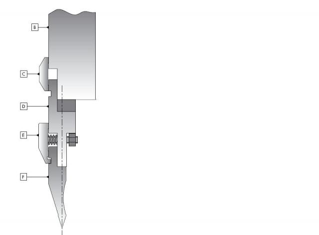
Я правильно понял, что Вы хотите полностью убрать адаптер D, и крепить пуансон F непосредственно к балке B станка?
Делать это категорически нельзя, так как торец балки не шлифован, а в состав адаптера D входят шлифованные клинья, с помощью которых Вы сможете получить линию гиба инструмента с точностью 0,01 мм.
Без адаптера, у Вас получится деталь с переменным углом.
- Цитата
Ссылка на сообщение
Поделиться на других сайтах
egen
1
-
- Жалоба
- Рассказать
Да собираюсь крепить пуансон непосредственно к балке, по крайней мере сейчас. Вот и хотел узнать как правильно это сделать просто снять адаптеры не получается их надо как то удалить из ЧПУ. Нет возможности купить матрицы в данный момент более низкие. Я как понял когда подбирали инструмент взяли за основу адаптеры меньшей высоты чем сейчас стоят и получилась как раз такая неприятность. С адаптерами которые у меня сейчас есть мне нужна матрица с высотой 80+подложка а у меня матрица 120.
- Цитата
Ссылка на сообщение
Поделиться на других сайтах
vad0000
350
-
- Жалоба
- Рассказать
Т.е. качеством изделий в данном случае Вы хотите пренебречь. Тогда сделайте следующее — подпишите все адаптеры и пометьте, в какой позиции на них были установлены клинья. В противном случае, Вам придется устанавливать адаптеры с помощью индикатора.
Мне нужно знать, как у Вас введены пуансоны — с учетом высоты адаптеров или нет? Если не помните — пришлите фотку запрограммированного пуансона. Как правило высота стандартного адаптера — 100 мм.
- Цитата
Ссылка на сообщение
Поделиться на других сайтах
egen
1
-
- Жалоба
- Рассказать
Т.е. качеством изделий в данном случае Вы хотите пренебречь. Тогда сделайте следующее — подпишите все адаптеры и пометьте, в какой позиции на них были установлены клинья. В противном случае, Вам придется устанавливать адаптеры с помощью индикатора.
Мне нужно знать, как у Вас введены пуансоны — с учетом высоты адаптеров или нет? Если не помните — пришлите фотку запрограммированного пуансона. Как правило высота стандартного адаптера — 100 мм.
В данный момент не могу фото выслать. Пуансон запрограммирован без учета высоты адаптера(просто высота указанная на пуансоне — 20мм(высота до полки)). Высота адаптера 150мм
- Цитата
Ссылка на сообщение
Поделиться на других сайтах
vad0000
350
-
- Жалоба
- Рассказать
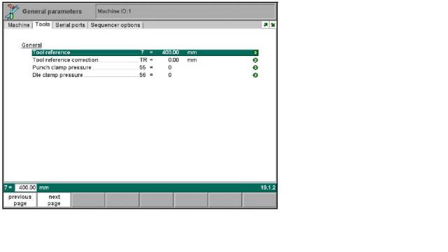
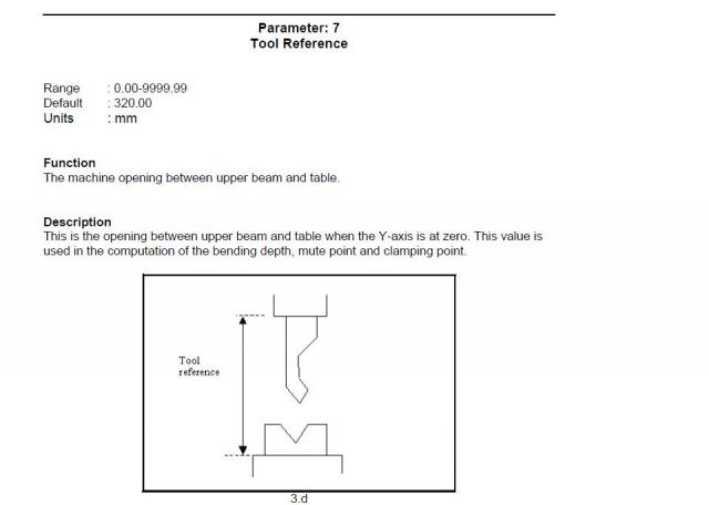
Тогда необходимо зайти в Машинные параметры станка и изменить референцию инструмента на величину адаптера, т.е. на 150 мм.
- Цитата
Ссылка на сообщение
Поделиться на других сайтах
egen
1
-
- Жалоба
- Рассказать
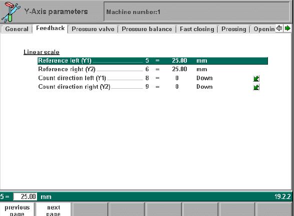
Спасибо попробую так. Я думал не много по другому сделать а конкретно изменить точки референции Y1 и Y2 в машинных параметрах. Я так когда то делал на стойке Advantage получилось и не плохо гнул станок хотя был 2,5 метровый а этот всего 1,2м я думаю тоже норм будет а потом как раз новую матрицу подвезут(может быть)
- Цитата
Ссылка на сообщение
Поделиться на других сайтах
vad0000
350
-
- Жалоба
- Рассказать
Так сделать не получилось бы, так как пришлось бы отнимать 150 мм от текущих значений, а значения референции не могут быть отрицательными.
- Цитата
Ссылка на сообщение
Поделиться на других сайтах
egen
1
-
- Жалоба
- Рассказать
на адвантадже точно значения 3-х значные были
- Цитата
Ссылка на сообщение
Поделиться на других сайтах
vad0000
350
-
- Жалоба
- Рассказать
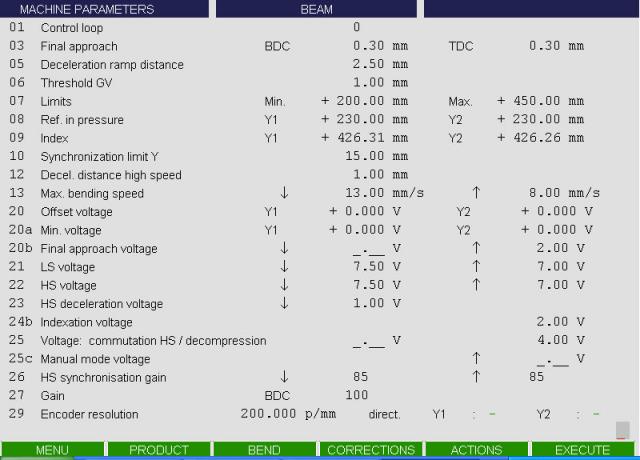
В CYBELEC также 3-х значные значения, т.к. отчет координат начинается снизу, от стола, а в DELEM — наоборот.
Привожу «скрин» машинных параметров CYBELEC.
9 параметр index CYBELEC — аналог reference DELEM.
- Цитата
Ссылка на сообщение
Поделиться на других сайтах
egen
1
-
- Жалоба
- Рассказать
Спасибо помогла ваша рекомендация. Гнет в принципе нормально. Одна проблема изготовлять надо коробку и как раз не хватает похоже высоты адаптера, чтобы согнуть последние гибы этой коробки(упираются в траверсу)
- Цитата
Ссылка на сообщение
Поделиться на других сайтах
zews
0
-
- Жалоба
- Рассказать
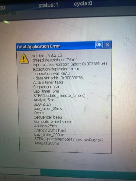
Листогиб (производитель Ermacsan) выдал ошибку (см. картинку). стойка DELEM 66W, кто-нибудь сталкивался с такой проблемой?
Изменено 28 ноября 2013 пользователем zews
- Цитата
Ссылка на сообщение
Поделиться на других сайтах
Tad
156
-
- Жалоба
- Рассказать
Третья версия… Сыровата, однако… Довольно часто распространенное сообщение системы о нарушении доступа к памяти по такому-то адресу. Причин может быть много: сбой работы приложения (delem.exe), неверная конфигурация приложения, порча какой-либо базы данных, проблемы с железом, в первую очередь с памятью… Вообще-то разработчик приложения, предполагая подобный баг, конкретизирует тип ошибки. А когда этого нету, т.е. реакция приложения выдачей конкретного сообщения на подобный сбой не была предусмотрена, имеем данную ситуацию. Надо добиваться разъяснения от разработчика приложения.
- Цитата
Ссылка на сообщение
Поделиться на других сайтах
xedex
77
- Автор
-
- Жалоба
- Рассказать
Листогиб (производитель Ermacsan) выдал ошибку (см. картинку). стойка DELEM 66W, кто-нибудь сталкивался с такой проблемой?
Это сообщение постоянно висит?
Или просто периодически появляется?
- Цитата
Ссылка на сообщение
Поделиться на других сайтах
Добрый день.
Есть китайский гибочник с ЧПУ, и назрели по нему некоторые вопросы:
1) создаем программу. вводим все параметры по чертежу (длина гиба, толщина, тип металла). рисуем. делаем автоматический выбор оснастки (у нас многоручьевая матрица и один пуансон, все это прописано в станке), ЧПУ считает усилие и тут возможно два варианта:
а) данного усилия не хватает на сгиб детали. и это будет не недогиб. в некоторых случаях может согнуть на 5-10 градусов, в некоторых на 5-10 не догнуть. но, иногда с первого раза рассчитывает усилие верно и деталь гнется либо без добавления коррекции либо с незначительной (2-3 градуса). отсюда вопрос: с чем это может быть связано? я не смог отследить какую-либо логику в формировании программы станком… иногда на длину гиба 150мм назначается усилие в 20 тонн, а иногда 2, при одинаковой толщине металла…
б) допустим, программа составлена нормально и все у нас гнется ок… погнули, программа сохранилась, выключили на ночь станок. утром включили, загрузили ту же программу начинаем гнуть и опять недогиб на какието дикие градусы (при этом есть точное понимание, что никто ночью к станку не приближался и не включал его). собирал аналитику в момент гиба, судя по графикам (если я их правильно понял), все ок и давит ровно настолько тонн, сколько указано в программе… в чем тут может быть дело?
2) периодически необходимо переворачивать матрицу. отводим ось Х, включаем ручной режим и начинаем опускать ось У. она опускается до некоторой точки (90мм, емнип), накидываю цепь на матрицу по бокам и жму педаль UP. далее начинается интересное: в некоторых случаях ось У без проблем поднимается вверх на высоту, достаточную для переворота матрицы, но в некоторых случаях поднимается на 20мм максимум и приходится ее опускать и поднимать вращением ручки энкодера. почему такое происходит?
3) при первом опускании матрицы (после включения станка и референции осей) она идет с очень большим перекосом по осям У1 и У2. иногда разница (и физически и в показаниях в стойке) доходит до 50мм. ниже может быть и ось У1 и ось У2, какойто закономерности нет… в чем может быть причина?
-
© 2015 Sonus Networks, Inc. All Rights Reserved Revision Date Revised By Comments 0.1 12/03/2015 Roman Kokes Initial Publication 0.2 3/16/2015 Grant Gist Internal review 0.4 3/26/2015 Andy N. Tran Customer review 1.0 4/13/2015 Tech Pubs Final Edit and Release SBC 1000/2000 Configuration Guide with Lync 2013 for Windstream/ LPAETEC SIP Trunk De …
SBC 1000 Controller, 39
-
Instruction Manual for AS380 Series Elevator Integrated Drive Controller AS380 Series Elevator Integrated Drive Controller Instruction Manual Publication Status: Standard Version: V2.15 All Copyright© reserved by Shanghai STEP Electric Corporation All rights reserved The information in this document is subject to change without prior notice. No part o …
AS380 Series Controller, 300
-
FEU2610 Field Equipment Controller Installation Instructions1ApplicationsThe MS-FEU2610-0U controller is a member of the Metasys® system Field Equipment Controller (FEC) family. The FEU26 is designed to run a variety of pre-engineered or user-programmed Heating, Ventilating, and Air Conditioning (HVAC) applications, and provides the inputs/outputs required for these applicatio …
FEU2610 Series Controller, 15
-
Installation Sheets Manual 121Gas Combustion Combination Controls and Systems Section GTechnical Bulletin G861Issue Date 0699© 1999 Johnson Controls, Inc.1Part No. 24-8143-553, Rev. A www.johnsoncontrols.comCode No. LIT-121920Figure 1: G861 Integrated FunctionDirect Spark Ignition ControlThe G861 is a microprocessor-based, 100% shutoff, direct spark, andremote flame sense, int …
G861 Series Controller, 12
-
www.LeonAudio.com.au01.PCinterfaceQL-PCi mk416 channel Cue Light control from your Touch Screen or Show Control PCControl up to 6 Cue Light Master StationsControl 240 Outstations across 96 channelsSimple 5 byte ASCII commandsReturn Status MonitoringSupports RS232 and 4 wire RS485• • • • • …
PCinterface QL-PCi Mk4 Controller, 82
-
DEUENGFRANDLITAESP3 4BSF 20×02-xx — 230 VBSF 40×12-xx — 24 VQuick Install GuideWarnungLebensgefahr durch elektrische Spannung!Lesen Sie die Bedienungsanleitung, vor Beginn der Installationsarbe-iten. Alle Installationsarbeiten sind in spannungsfreiem Zustand durch-zuführen.WarningElectrical voltage! Danger to life!Read operating manual before starting installation work. All in …
BSF 20×02 series Controller, 4
-
ISP Programming Tool Sep. 05, 2018 Page 1 of 11 Rev 2.05 ISP PROGRAMMING TOOL USER MANUAL ARM® Cortex®- M 32-bit Microcontroller NuMicro® ISP Programming Tool User Manual The information described in this document is the exclusive intellectual property of Nuvoton Technology Corporation and shall not be reproduced without permission from Nuvoton. Nuvoton …
NuMicro ARM Cortex M Controller, 11
-
VPPI-…-S1/-S1BTProportional-pressure regulatorFesto SE & Co. KGRuiter Straße 8273734 EsslingenDeutschland+49 711 347-0 www.festo.comOperating instructions81567152021-11a[8156717]Translation of the original instructions© 2021 all rights reserved to Festo SE & Co. KGBluetooth®, IO-Link® are registered trademarks of the respective trademarkowners in certain countries …
VPPI S1 Series Controller, 4
-
10400244-002 Jul 2013 ©2009,2013 Overland Storage, Inc. Page 1 of 4This document describes how to remove and replace the Library Controller card in a NEO 2000e or 4000e library. It is also used for legacy NEO libraries that have been upgraded to an E-Series.WARNING: To reduce the risk of electric shock or damage to equipment, always remove any power cords while working w …
NEO 2000E Controller, 4