-
Contents
-
Table of Contents
-
Troubleshooting
-
Bookmarks
Quick Links
Maintenance and troubleshooting
record sliding door system 20
Manufacturer:
agtatec ag
Allmendstrasse 24
CH-8320 Fehraltorf
Switzerland
Tel. no. :
+41 44 954 91 91
Fax. no. :
+41 44 954 92 00
www.agta-record.com
© Copyright by agtatec ag, CH-8320 Fehraltorf
Distributor:
September 2009
Article no. 102-020.110.805
Related Manuals for Record 102-020.110.805
Summary of Contents for Record 102-020.110.805
-
Page 1
Maintenance and troubleshooting record sliding door system 20 Manufacturer: Distributor: agtatec ag Allmendstrasse 24 CH-8320 Fehraltorf Switzerland Tel. no. : +41 44 954 91 91 Fax. no. : +41 44 954 92 00 www.agta-record.com © Copyright by agtatec ag, CH-8320 Fehraltorf September 2009 Article no. -
Page 2: Table Of Contents
4.1. System information on BDE-D ………………7 4.2. Error display and troubleshooting ………………8 Taking out of service and disposal …………..14 5.1. Taking out of service…………………..14 5.2. Dismantling and disposal ………………..14 record sliding door system 20 Article no. 102-020.110.805 page 2…
-
Page 3: General Remarks
General remarks 1.1. Goal and application field of maintenance and service These instructions describe the maintenance and troubleshooting of the record system 20 and are intended for qualified and authorized service technicians of the record system 20 automatic sliding door installation.
-
Page 4: Safety Instructions
Safety instructions Safety instructions The record system 20 sliding door has been constructed with state of the art technology and ac- cording to recognised technical safety regulations. It complies with the requirements of Machine Guideline 2006/42/EG. Nevertheless, danger can arise for the end-user if the installation is not used as intended.
-
Page 5: Instructions For Maintenance And Service
Mechanical control WARNING Mechanical works on record system 20 may only be performed when the installa- tion is disconnected from the mains and the battery (if existing) is disconnected. Control running gear: the stabilizer-wheels must easily be rolled by hand, with system 20 •…
-
Page 6: Logbook
Instructions for maintenance and service Control manual unlocking devices inside and/or outside (if applicable) and keep record. • Make operator check card and badge readers (if applicable). • Check key-operated contact (if applicable). • Emergency or battery service (if existing): switch off mains voltage and check functions •…
-
Page 7: Repairs
Press key about 2 seconds Browse through informations by tapping the key Back to main display by pressing the key or automatically after 20 seconds. record sliding door system 20 Article no. 102-020.110.805 page 7…
-
Page 8: Error Display And Troubleshooting
Despite the upcoming error the door can provisionally be locked as follows: Set BDE-D on MANUAL operating mode • Slide door leaves by hand into closed position • Set BDE-D on LOCKED operating mode • Door remains closed and locked • record sliding door system 20 Article no. 102-020.110.805 page 8…
-
Page 9
On RED installations emergency opening switch has been actuated. Timeout open. time 80% of escape route opening not reached within 3 sec. Control with FPC, adjust opening speed. Under „Status”, opening time + 400 ms. record sliding door system 20 Article no. 102-020.110.805 page 9… -
Page 10
Control safety alarm. Control external signal. Watchdog fault Replace control unit. VOK open unl. Repeat locking and unlocking procedures. Connection cable might be missing or is not properly plugged in. Check locking settings. record sliding door system 20 Article no. 102-020.110.805 page 10… -
Page 11
RED / Control all motor cables. Rotating direction of jumper JP4 is wrong. Jumper for rotating direction does not function with RED and DUO. Set rotating direction with connecting clamp. record sliding door system 20 Article no. 102-020.110.805 page 11… -
Page 12
RED / Different software in both microprocessors. Update software in STM 20 DUO/RED. Batt. not charged Battery is not fully charged. Message disappears from display complet. in case of full charge. record sliding door system 20 Article no. 102-020.110.805 page 12… -
Page 13
SENS AA 1 AA 1 actuating device outside 1 SENS AA 2 AA 2 actuating device outside 2 FEM-0 FEM-0 extended functions module 0 FEM-1 FEM-1 extended functions module 1 record sliding door system 20 Article no. 102-020.110.805 page 13… -
Page 14: Taking Out Of Service And Disposal
5.1. Taking out of service When the record system 20 installation is discontinued or taken out of service, it is disconnected from the power supply and the battery (if relevant) is disconnected. After every temporary discontinuation, a new commissioning has to be carried out.
- Manuals
- Brands
- Record Manuals
- Door Opening System
- STM 20 RED/DUO
- Manual
-
Contents
-
Table of Contents
-
Bookmarks
Quick Links
Control
Sliding door system 20
© Copyright agtatec AG 2011
Manufacturer
Service-Hotline
Distributer
agtatec ag
Allmendstrasse 24
CH-8320 Fehraltorf
Art. Nr. 102-020401135
Related Manuals for Record STM 20
Summary of Contents for Record STM 20
-
Page 1
Control Sliding door system 20 © Copyright agtatec AG 2011 Manufacturer Service-Hotline Distributer agtatec ag Allmendstrasse 24 CH-8320 Fehraltorf Art. Nr. 102-020401135… -
Page 2: Table Of Contents
2.1. Controlling elements on STM 20 ………………7 2.2. Type plate STM 20 ………………….8 2.3. Wiring diagram control module STM 20 …………….10 Control module STM 20 RED/DUO…………..12 3.1. Controlling elements on STM 20 RED/DUO…………..12 3.2. Applications ……………………12 3.2.1.
-
Page 3
Table of contents / Index 6.2. Applications ……………………31 6.2.1. Escape and rescue routes as RED installation …………..31 6.2.2. Heavy door leafs as DUO installation…………….31 6.3. Type plate STM 22 RED/DUO………………31 6.4. Wiring diagram control module STM 22 DUO/RED…………34 6.5. -
Page 4
Unavailable applications…………20 Escape and rescue routes as RED installation ..13, 25, 31 Wiring diagram control module STM 20……10 Wiring diagram control module STM 20 RED/DUO ..16 Wiring diagram control module STM 21……22 General……………… 5 Wiring diagram control module STM 21 RED….27 Wiring diagram control module STM 22 DUO/RED ..34… -
Page 5: General
Table of contents / Index General 1.1. Document identification Name: B6_Control_SYS20_EN_V1.3.doc Version: V1.3 Serial no.: 102-020401135 1.2. Structure of the documentation The documentation of the system 20 is divided into different manuals, in order to reduce file size and to simplify the handling. The structure of the document is as follows (B1 =book 1): B1_General B2_Assembly STA…
-
Page 6: Instruction Manual
Battery / Accumulator Operator casing Fanlight Protective screen B6_Control General Control module STM 20 Control module STM 20 RED / DUO Control module STM 21 Control module STM 21 RED Control module STM 22 RED / DUO B7_Commissioning General Principles for commissioning…
-
Page 7: Control Module Stm 20
Controlling elements on STM 20 Control module STM 20 works with an active HIGH level. That means that a minimum of +24V is required to activate a function. Safety functions of inputs are activated in case of interruption. 0V is connected to the ground.
-
Page 8: Type Plate Stm 20
Control module STM 20 2.2. Type plate STM 20 STM20 Jumper Change of function Allows emergency stop and HEA to be connected in series: Jumper on HEA Emergency stop Influences motor-driven braking function in case of power…
-
Page 9
Control module STM 20 9 pulses Back to factory settings (afterwards an emergency stop or a reset must be actuated within 10 seconds) The function emergency-stop with reset can only be actuated if the INPUT/OUTPUT parameter Emergency-Stop with Reset is active!! 14 pulses Hardware-Reset will be done after approx 12 sec. -
Page 10: Wiring Diagram Control Module Stm 20
Control module STM 20 2.3. Wiring diagram control module STM 20 102-020109935 Art. Nr. 102-020401135 10 / 36 B6_Control_SYS20_EN_V1.3.doc…
-
Page 11
Control module STM 20 102-020109935 Art. Nr. 102-020401135 11 / 36 B6_Control_SYS20_EN_V1.3.doc… -
Page 12: Control Module Stm 20 Red/Duo
3.1. Controlling elements on STM 20 RED/DUO Control module STM 20 RED/DUO works with an active HIGH level. That means that a minimum of +24V is required to activate a function. Protective inputs are activated in case of interruption. OV is connected to the ground. This connection can be interrupted for test reasons by use of the ground screw, located next to terminal 12.
-
Page 13: Escape And Rescue Routes As Red Installation
Control module STM 20 RED/DUO 3.2.1. Escape and rescue routes as RED installation NOTE Control module STM 20 RED/DUO with RED software has been tested according EN 13849-1:2006, category 3 PLd. 3.2.2. Heavy door leafs as DUO installation NOTE Control module STM 20 RED/DUO with DUO software has been tested according EN 13849-1:2006, category 2 PLc.
-
Page 14
Control module STM 20 RED/DUO On RED and DUO installation D-ST & EST-R Factory setting Fixing connecting clamp to upper part of toothed belt — Shunt EST-L position remains unchanged ! Standard Master opera- Slave – only in case of two STM… -
Page 15
Control module STM 20 RED/DUO Extra printed circuit board ELS (ZLP-ELS) Extra printed circuit board AKI (ZLP-AKI) CAN bus plug for FPC-servicing Reserved for future modules Encoder motor 1 Encoder motor 2 (not necessary for DUO-applications) Reserved for future modules… -
Page 16: Wiring Diagram Control Module Stm 20 Red/Duo
Control module STM 20 RED/DUO 3.4. Wiring diagram control module STM 20 RED/DUO 102-020110534 Art. Nr. 102-020401135 16 / 36 B6_Control_SYS20_EN_V1.3.doc…
-
Page 17
Control module STM 20 RED/DUO 102-020110534 Art. Nr. 102-020401135 17 / 36 B6_Control_SYS20_EN_V1.3.doc… -
Page 18: Components Red/Duo System
Mechanically there is no difference between a pure DUO system and a RED system (with certifica- tion for escape and rescue routes). On a RED installation there is a special RED-software for CPU1 and CPU2 loaded on the control module STM 20 RED/DUO. This software complies with the standard: EN 13849-1:2006 Category 3 PLd.
-
Page 19: Control Module Stm 21
Control module STM 21 Control module STM 21 4.1. Controlling elements on STM 21 Control module STM 21 works with an active HIGH level. That means that a minimum of +24V is required to activate a function. Protective inputs are activated in case of interruption. OV is con- nected to the ground.
-
Page 20: Application Field Of Control Module Stm 21
Control module STM 21 4.2. Application field of control module STM 21 NOTE Control module STM 21 is exclusively used in combination with a weaker drive unit featuring restricted functional requirements and limited door weight. 4.2.1. Typical range of applications …
-
Page 21
Control module STM 21 Re-plugging for monitoring devices EST R Standard D-ST & EST L – subsequently reboot of control necessary Light-emitting diode Meaning Red control-LED For multifunctional key S1 – blinks when key is pressed Change plugging to reverse rotational direction (EST-R) … -
Page 22: Wiring Diagram Control Module Stm 21
Control module STM 21 4.4. Wiring diagram control module STM 21 102-021110650 Art. Nr. 102-020401135 22 / 36 B6_Control_SYS20_EN_V1.3.doc…
-
Page 23
Control module STM 21 102-021110650 Art. Nr. 102-020401135 23 / 36 B6_Control_SYS20_EN_V1.3.doc… -
Page 24: Control Module Stm 21 Red
Control module STM 21 RED Control module STM 21 RED 5.1. Controlling elements on STM 21 RED Control module STM 21 RED works with an active HIGH level. That means that a minimum of +24V is required to activate a function. Protective inputs are activated in case of interruption. OV is connected to the ground.
-
Page 25: Escape And Rescue Routes As Red Installation
Control module STM 21 RED 5.2.1. Escape and rescue routes as RED installation NOTE Control module STM 21 RED with RED software has been tested according EN 13849-1:2006, category 3 PLd. 5.3. Type plate STM 21 RED STM 21 RED Jumper Change of function Allows emergency stop and HEA to be connected in series…
-
Page 26
Control module STM 21 RED Multifunctional key Function, after pulses have been given 1 pulse Releases an opening movement (AKI) 2 pulses Calibrating ELS 3 pulses Calibrating door parameters 4 pulses Entering programming level 5 pulses Redundancy test, if system connected to mains voltage … -
Page 27: Wiring Diagram Control Module Stm 21 Red
Control module STM 21 RED 5.4. Wiring diagram control module STM 21 RED 102-020110534 Control module 21 RED Art. Nr. 102-020401135 27 / 36 B6_Control_SYS20_EN_V1.3.doc…
-
Page 28
Control module STM 21 RED Control module 21 RED 102-020110534 Art. Nr. 102-020401135 28 / 36 B6_Control_SYS20_EN_V1.3.doc… -
Page 29: Components Red System
Control module STM 21 RED 5.5. Components RED system MS Power set STM 21 RED 102-021808964 Control module STM 21 RED 1 pc. ATE 21 (Linix) 1 pc. ATE 21 Socket Cable and installation material BAT 20 RED 102-020808835 In the two above mentioned assembly kits, there are all the necessary components included for a…
-
Page 30: Control Module Stm 22 Red/Duo
Control module STM 22 RED/DUO Control module STM 22 RED/DUO 6.1. Controls on STM 22 RED/DUO The control module STM 22 RED/DUO works with an active HIGH level. To activate the function +24V must be present. Safety inputs will be activated by an interruption. The basic signal 0V is connected to the protective earth.
-
Page 31: Applications
Control module STM 22 RED/DUO 6.2. Applications The control module STM 22 RED/DUO will be – depending on the implemented software and cor- responding admissions – used for the following installations. 6.2.1. Escape and rescue routes as RED installation NOTE The STM 22 RED/DUO control module with RED Software complies with EN 13849-1:2006, Category 3 PLd.
-
Page 32
Control module STM 22 RED/DUO Jumper Change of function Allows emergency stop and HEA to be connected in series:: Jumper on HEA Emergency stop Not equipped Syst.-conditioned, internal Not visible – reserved for future applications If used as RED+DUO-installation D-ST &… -
Page 33
Control module STM 22 RED/DUO Battery 2 (just use for RED-applications) Locking Motor brake ATE motor 1 (The DUO-application can be driven with 1 mo- tor only) ATE Motor 2 CAN-Bus / CAN Sensors Additional printed circuit board ELS (ZLP-ELS) Additional printed circuit board AKI (ZLP AKI) CAN-Bus service plug for FPC Reserved for future modules… -
Page 34: Wiring Diagram Control Module Stm 22 Duo/Red
Control module STM 22 RED/DUO 6.4. Wiring diagram control module STM 22 DUO/RED 102-020110534 Art. Nr. 102-020401135 34 / 36 B6_Control_SYS20_EN_V1.3.doc…
-
Page 35
Control module STM 22 RED/DUO 102-020110534 Art. Nr. 102-020401135 35 / 36 B6_Control_SYS20_EN_V1.3.doc… -
Page 36: Components Red/Duo Installations
Overview of the additional components Basically, the components will be mounted and wired analogue to a normal sliding door. Below we refer to the necessary additional components for a RED installation. STM 20 RED/DUO Mot 1 BAT 20 RED Mot 2…
-
Contents
-
Table of Contents
-
Troubleshooting
-
Bookmarks
Quick Links
User manual
S20
automatic door systems — this is record!
Translation of the original manual
Related Manuals for Record S20 Series
Summary of Contents for Record S20 Series
- Page 1
User manual automatic door systems — this is record! Translation of the original manual… -
Page 2: Table Of Contents
Table of contents Table of contents Safety ……………………. Presentation of warning signs ………………….Intended purpose of use …………………… General safety and accident prevention regulations …………..1.3.1 Intervention rules on sites ………………….State of technology……………………. Personal protective equipment ………………….. Spare parts and liability ……………………Security inspection according EN 16005 …………
- Page 3
Table of contents Description………………….General view ……………………..Safety equipment and operating elements ………………4.2.1 Opening and security sensors (combined) ………………4.2.2 Collision detection …………………….. 4.2.3 Security sensors side panel ………………….Components of the system ………………….Technical data ………………..Operation ………………….Selection of operating modes (BDE-D) ……………… - Page 4
Table of contents 8.3.2 Manual closing — Step 2 ……………………Operating door in emergency ………………….8.4.1 Emergency opening with current supply ………………8.4.2 Emergency opening in case of power failure with a back-up battery (optional)……8.4.3 Emergency operating using Bowden cable (Option) …………..Taking out of service and disposal ………….. -
Page 5: Safety
Safety Safety Presentation of warning signs Various symbols are used in this guide for easier understanding: NOTICE Useful advice and information to ensure correct and efficient workflow of the system. IMPORTANT Specific details which are essential for trouble-free operation of the sys- tem.
-
Page 6: General Safety And Accident Prevention Regulations
Safety General safety and accident prevention regulations NOTICE If necessary, the country specific regulations have to be adhered to. NOTICE This system is not intended to be used by persons (including children from the age of
with limited physical, sensory or mental abilities or with a lack of experience and/or knowledge.
-
Page 7: Intervention Rules On Sites
Safety CAUTION Unexpected OPENING / CLOSING / ROTATION • Bruises and contusions from the door wings/apron No persons or objects are allowed in the opening area of the door. No safety devices (sensors) should be removed or disabled. …
-
Page 8: State Of Technology
Safety NOTICE Ensure regularly that all safety systems are in good working order. State of technology This system was developed using state of the art technology and officially recognized technical safety regulations. The system, depending on its options and diameter, comply with the requirements of the Machine Guidelines 2006/42/EG as well as EN 16005 and DIN 18650 (D).
-
Page 9: Spare Parts And Liability
Safety Safety shoes protect the feet from crushing, falling parts and slipping on surfaces. The puncture resistance of the shoes ensures, that pointy objects do not penetrate the foot. The high-visibility vest is used to make the personnel stand out and therefore to be seen.
-
Page 10: Security Inspection According En 16005
Security inspection according EN 16005 Security inspection according EN 16005 Like the German standard DIN 18650, the EN 16005 describes the requirements and the test me- thods for the safe use of power-operated pedestrian doors. The EN 16361 describes the require- ments for the production process and documentation / classification of the doors.
-
Page 11: Protection During Closing Cycle
Security inspection according EN 16005 Term according to DIN Description EN 16005 Main closing edge Edge of a door wing, whose distance from the parallel opposing closing edge or opposing surface determines the usable open width. Opposing / counter clo- Closing edge formed by the main closing edge of opposing closing wing, a sing edge fixed edge or a surface, against which the wing moves (i.e.
-
Page 12: Din Aluminium Finishing Profiles
Security inspection according EN 16005 2.3.1 DIN aluminium finishing profiles Solution: ▪ DIN aluminium finishing profiles + safety distances ▪ DIN aluminium finishing profiles See Book B1 „General Information“ Chapter „General Plans“ Example D-STA 32 mm with side screen and cladding Version DIN aluminium finishing profiles (P1752) Version rubber finishing profiles (P1760) NOTICE The version with rubber finishing profiles is not EN 16005 compliant with…
-
Page 13: Protective Screen
Security inspection according EN 16005 If S ≤ 8 mm then t ≤ 0 mm S ≤ 8 mm → Y ≤ 0 mm If S > 8 mm then t ≥ 25 mm S > 8 mm → Y ≥ 25 mm Figure b) Shearing and drawing-in protection Figure d) Finger protection (drawing-in) 2.3.3…
-
Page 14: Additional Requirements For Doorsets In Escape Routes And Emergency Exits
Security inspection according EN 16005 2.4.2 Additional requirements for doorsets in escape routes and emergency exits When an operating mode selector is used, the mode of operation shall be clearly identified and marked on the operating mode selector. If a «locked» mode of operation is available, the mode of operation shall be protected, e.g. by an ac- cess code or a key, so that changes can only be made by authorised personnel.
-
Page 15: General Information
General information General information Purpose and use of the instructions These instructions are an integral part of the system and enable efficient and safe handling of the sys- tem. In order to ensure proper functioning, the instructions must be accessible at all times and kept in the immediate area of the system.
-
Page 16: Target Groups
General information Target groups This operating manual is intended for the target groups listed below: ▪ Operating entity of the system: the person who is responsible for the technical maintenance of this system ▪ Operator of the system: the person who operates the system every day and has been suitably instructed General definitions of terms The following terms are used in manuals for easier understanding: Term:…
-
Page 17: Description
Description Description General view Example of 1-wing sliding door Components Pos. Components Top guide Combination sensor Wall connection –side panel Wall connection – wing side Side panel Wing Emergency release (unlock) Drive complete BAL_S20_EN_1V0_REC_121-006454590 17/ 33…
-
Page 18: Safety Equipment And Operating Elements
Description Safety equipment and operating elements Pos. Components Pos. Components Trigger and safety sensor / combinati- Key switch BDE-V (option) on sensor (inside and outside) Control unit BDE-D Manual release 4.2.1 Opening and security sensors (combined) Each passage area is monitored with opening and security sensors. If an opening or security sensor is activated during the closing process while in AUTOMATIC or ONEWAY TRAFFIC operating mode, then the respective sliding door will re-open/reverse again.
-
Page 19: Technical Data
Operation Technical data NOTICE The power connection must be installed by a licensed electrician. The power must be able to be shut off via a main switch or residual current circuit breaker (on-site). NOTICE For underfloor drives, an FI should be installed by the customer. Description Designation Underfloor sliding door system (complete door s.) S20 SU…
-
Page 20: Operation
Operation Operation Selection of operating modes (BDE-D) The electronic control unit BDE-D is a user-friendly input/output module to control and customise (op- tional) the system operation. The backlit LCD display informs about the system status by means of symbols and plain text. Error messages are displayed as text. Button Operating Symbol dis-…
-
Page 21: Selection Of Operating Modes (Red)
Operation Selection of operating modes (RED) The electronic control unit BDE-D is a user-friendly input and output unit to control and customise (op- tional) the door operation. The LCD display with backlight gives information about the door status with symbols and clear text. Error messages are displayed as text. Control unit BDE-D ▪…
-
Page 22: Selection Of Special Functions (Red)
Operation ▪ Door opens unhin- dered from inside or Reduced opening width outside ▪ Reduced opening width (winter ope- ning) ▪ Reduced opening width is set to the minimum authorised value according to country-specific gui- delines and cannot be further diminis- hed via BDE-D NOTICE The reduced opening width is also effective with operating modes…
-
Page 23: Operating Mode Display
Operation Operating mode Function Automatic mode with total This operating mode is the standard operating mode. opening width Through triggering of a e.g. Radar, the door opens. After the pre-set door time delay, the door closes. Continuously open and manual Door opens and stays in open position.
-
Page 24: Locking The Control Unit With A Key (Option)
Operation NOTICE The installation remains in the mode of operation previously selected Locking the control unit with a key (option) IMPORTANT Standard EN 16005 requires protection, for the mode selection of operation of pedestrian automatic doors, used as emergency exits so that they may not be inadvertently locked when the building is in use.
-
Page 25: Servicing And Maintenance
Servicing and maintenance Servicing and maintenance General remarks According to the legal provision in force, the operating entity of the automatic door is responsible for its maintenance and for the user’s safety, as soon as the installation has been handed over. The regular inspection of single elements by the operator requires little time investment and reinforces the prevention of accidents caused by an inappropriate use of the door.
-
Page 26: Monthly Inspection Work To Be Carried Out By The Operating Company
Servicing and maintenance Monthly inspection work to be carried out by the operating company The monthly inspection and maintenance of individual elements by the operating company requires little time and serves the reliable function, increased service life and operational safety of the system. Test / inspection Procedure Expected result…
- Page 27
Servicing and maintenance Test / inspection Procedure Expected result ▪ Set the door to manual ope- ▪ The door leaf must be pro- Continuous floor guide (instead of punctual door leaf guide) ration (see chapter «Selecting perly guided ▪ The movement of the door special functions») ▪… -
Page 28: Malfunctions
Malfunctions Malfunctions Behavior in event of faults In the event of an irregularity or malfunction, different displays are shown depending on the control unit connected. IMPORTANT If malfunctions that endanger the safety of individuals occur, the system must be turned off. It may not be turned back on until the problem has been resolved by a professional and the danger no long exists.
-
Page 29: Control Unit Bde-D Does Not React
Malfunctions 8.1.4 Control unit BDE-D does not react If the control panel does not react when the keys are pressed or if no message appears on the dis- play, a reset of the control panel could eliminate the problem. Proceed as follows: RESET HARDWARE BDE-D Press E key >…
-
Page 30: Manual Closing
Malfunctions Manual closing Initial situation: Electric power is supplied. Door remains blocked in open position. NOTICE Depending on the kind of failure, the procedure for a manual closing will be diffe- rent. Please follow the steps described below. 8.3.1 Manual closing — step 1 Function Display Description…
-
Page 31: Operating Door In Emergency
Malfunctions ▪ Push the door manually into the closed positi- ▪ Actuate the release lever clockwise until the locking bolt releases and locks the door. ▪ Check by hand whether the door is really lo- cked. ▪ Leaving the building only possible via a se- cond exit Call service station (phone number shown on display)
- Page 32
Malfunctions 8.4.3.2 Procedure for an emergency opening Emergency opening ▪ Open the unlocking flap ▪ Pulling the unlocking flap downwards unlocks the door ▪ Display on the BDE-D → Error No. 31 / Emergency stop ▪ The door can be slid open by hand 8.4.3.3 Closing and locking the door ▪… -
Page 33: Taking Out Of Service And Disposal
All machine parts must be sorted by type of material and disposed of according to local regulations and guidelines. NOTICE The record door systems can be completely disassembled in reverse order. The automatic door mainly consists of the following materials: Aluminum: ▪…
- Page 34
Contact record UK limited Head Office: Unit D, 9 Watt Place — Hamilton International Park — Blantyre — G72 0AH — UK Central Office: Batley Business Centre — Unit 40 — Annexe 2 — Technology Drive — Batley — Wf17 6ER — UK Southern Office: 17 Invincible Road — Farnborough — Gu14 7QU — UK tel.: +44 1698 376411 — fax: +44 1698 376422 -…
This manual is also suitable for:
S20 su
-
Contents
-
Table of Contents
-
Troubleshooting
-
Bookmarks
Quick Links
User manual
S20
automatic door systems — this is record!
Translation of the original manual
Related Manuals for Record S20 Series
Summary of Contents for Record S20 Series
- Page 1
User manual automatic door systems — this is record! Translation of the original manual… -
Page 2: Table Of Contents
Table of contents Table of contents Safety ……………………. Presentation of warning signs ………………….Intended purpose of use …………………… General safety and accident prevention regulations …………..1.3.1 Intervention rules on sites ………………….State of technology……………………. Personal protective equipment ………………….. Spare parts and liability ……………………Security inspection according EN 16005 …………
- Page 3
Table of contents Description………………….General view ……………………..Safety equipment and operating elements ………………4.2.1 Opening and security sensors (combined) ………………4.2.2 Collision detection …………………….. 4.2.3 Security sensors side panel ………………….Components of the system ………………….Technical data ………………..Operation ………………….Selection of operating modes (BDE-D) ……………… - Page 4
Table of contents 8.3.2 Manual closing — Step 2 ……………………Operating door in emergency ………………….8.4.1 Emergency opening with current supply ………………8.4.2 Emergency opening in case of power failure with a back-up battery (optional)……8.4.3 Emergency operating using Bowden cable (Option) …………..Taking out of service and disposal ………….. -
Page 5: Safety
Safety Safety Presentation of warning signs Various symbols are used in this guide for easier understanding: NOTICE Useful advice and information to ensure correct and efficient workflow of the system. IMPORTANT Specific details which are essential for trouble-free operation of the sys- tem.
-
Page 6: General Safety And Accident Prevention Regulations
Safety General safety and accident prevention regulations NOTICE If necessary, the country specific regulations have to be adhered to. NOTICE This system is not intended to be used by persons (including children from the age of
with limited physical, sensory or mental abilities or with a lack of experience and/or knowledge.
-
Page 7: Intervention Rules On Sites
Safety CAUTION Unexpected OPENING / CLOSING / ROTATION • Bruises and contusions from the door wings/apron No persons or objects are allowed in the opening area of the door. No safety devices (sensors) should be removed or disabled. …
-
Page 8: State Of Technology
Safety NOTICE Ensure regularly that all safety systems are in good working order. State of technology This system was developed using state of the art technology and officially recognized technical safety regulations. The system, depending on its options and diameter, comply with the requirements of the Machine Guidelines 2006/42/EG as well as EN 16005 and DIN 18650 (D).
-
Page 9: Spare Parts And Liability
Safety Safety shoes protect the feet from crushing, falling parts and slipping on surfaces. The puncture resistance of the shoes ensures, that pointy objects do not penetrate the foot. The high-visibility vest is used to make the personnel stand out and therefore to be seen.
-
Page 10: Security Inspection According En 16005
Security inspection according EN 16005 Security inspection according EN 16005 Like the German standard DIN 18650, the EN 16005 describes the requirements and the test me- thods for the safe use of power-operated pedestrian doors. The EN 16361 describes the require- ments for the production process and documentation / classification of the doors.
-
Page 11: Protection During Closing Cycle
Security inspection according EN 16005 Term according to DIN Description EN 16005 Main closing edge Edge of a door wing, whose distance from the parallel opposing closing edge or opposing surface determines the usable open width. Opposing / counter clo- Closing edge formed by the main closing edge of opposing closing wing, a sing edge fixed edge or a surface, against which the wing moves (i.e.
-
Page 12: Din Aluminium Finishing Profiles
Security inspection according EN 16005 2.3.1 DIN aluminium finishing profiles Solution: ▪ DIN aluminium finishing profiles + safety distances ▪ DIN aluminium finishing profiles See Book B1 „General Information“ Chapter „General Plans“ Example D-STA 32 mm with side screen and cladding Version DIN aluminium finishing profiles (P1752) Version rubber finishing profiles (P1760) NOTICE The version with rubber finishing profiles is not EN 16005 compliant with…
-
Page 13: Protective Screen
Security inspection according EN 16005 If S ≤ 8 mm then t ≤ 0 mm S ≤ 8 mm → Y ≤ 0 mm If S > 8 mm then t ≥ 25 mm S > 8 mm → Y ≥ 25 mm Figure b) Shearing and drawing-in protection Figure d) Finger protection (drawing-in) 2.3.3…
-
Page 14: Additional Requirements For Doorsets In Escape Routes And Emergency Exits
Security inspection according EN 16005 2.4.2 Additional requirements for doorsets in escape routes and emergency exits When an operating mode selector is used, the mode of operation shall be clearly identified and marked on the operating mode selector. If a «locked» mode of operation is available, the mode of operation shall be protected, e.g. by an ac- cess code or a key, so that changes can only be made by authorised personnel.
-
Page 15: General Information
General information General information Purpose and use of the instructions These instructions are an integral part of the system and enable efficient and safe handling of the sys- tem. In order to ensure proper functioning, the instructions must be accessible at all times and kept in the immediate area of the system.
-
Page 16: Target Groups
General information Target groups This operating manual is intended for the target groups listed below: ▪ Operating entity of the system: the person who is responsible for the technical maintenance of this system ▪ Operator of the system: the person who operates the system every day and has been suitably instructed General definitions of terms The following terms are used in manuals for easier understanding: Term:…
-
Page 17: Description
Description Description General view Example of 1-wing sliding door Components Pos. Components Top guide Combination sensor Wall connection –side panel Wall connection – wing side Side panel Wing Emergency release (unlock) Drive complete BAL_S20_EN_1V0_REC_121-006454590 17/ 33…
-
Page 18: Safety Equipment And Operating Elements
Description Safety equipment and operating elements Pos. Components Pos. Components Trigger and safety sensor / combinati- Key switch BDE-V (option) on sensor (inside and outside) Control unit BDE-D Manual release 4.2.1 Opening and security sensors (combined) Each passage area is monitored with opening and security sensors. If an opening or security sensor is activated during the closing process while in AUTOMATIC or ONEWAY TRAFFIC operating mode, then the respective sliding door will re-open/reverse again.
-
Page 19: Technical Data
Operation Technical data NOTICE The power connection must be installed by a licensed electrician. The power must be able to be shut off via a main switch or residual current circuit breaker (on-site). NOTICE For underfloor drives, an FI should be installed by the customer. Description Designation Underfloor sliding door system (complete door s.) S20 SU…
-
Page 20: Operation
Operation Operation Selection of operating modes (BDE-D) The electronic control unit BDE-D is a user-friendly input/output module to control and customise (op- tional) the system operation. The backlit LCD display informs about the system status by means of symbols and plain text. Error messages are displayed as text. Button Operating Symbol dis-…
-
Page 21: Selection Of Operating Modes (Red)
Operation Selection of operating modes (RED) The electronic control unit BDE-D is a user-friendly input and output unit to control and customise (op- tional) the door operation. The LCD display with backlight gives information about the door status with symbols and clear text. Error messages are displayed as text. Control unit BDE-D ▪…
-
Page 22: Selection Of Special Functions (Red)
Operation ▪ Door opens unhin- dered from inside or Reduced opening width outside ▪ Reduced opening width (winter ope- ning) ▪ Reduced opening width is set to the minimum authorised value according to country-specific gui- delines and cannot be further diminis- hed via BDE-D NOTICE The reduced opening width is also effective with operating modes…
-
Page 23: Operating Mode Display
Operation Operating mode Function Automatic mode with total This operating mode is the standard operating mode. opening width Through triggering of a e.g. Radar, the door opens. After the pre-set door time delay, the door closes. Continuously open and manual Door opens and stays in open position.
-
Page 24: Locking The Control Unit With A Key (Option)
Operation NOTICE The installation remains in the mode of operation previously selected Locking the control unit with a key (option) IMPORTANT Standard EN 16005 requires protection, for the mode selection of operation of pedestrian automatic doors, used as emergency exits so that they may not be inadvertently locked when the building is in use.
-
Page 25: Servicing And Maintenance
Servicing and maintenance Servicing and maintenance General remarks According to the legal provision in force, the operating entity of the automatic door is responsible for its maintenance and for the user’s safety, as soon as the installation has been handed over. The regular inspection of single elements by the operator requires little time investment and reinforces the prevention of accidents caused by an inappropriate use of the door.
-
Page 26: Monthly Inspection Work To Be Carried Out By The Operating Company
Servicing and maintenance Monthly inspection work to be carried out by the operating company The monthly inspection and maintenance of individual elements by the operating company requires little time and serves the reliable function, increased service life and operational safety of the system. Test / inspection Procedure Expected result…
- Page 27
Servicing and maintenance Test / inspection Procedure Expected result ▪ Set the door to manual ope- ▪ The door leaf must be pro- Continuous floor guide (instead of punctual door leaf guide) ration (see chapter «Selecting perly guided ▪ The movement of the door special functions») ▪… -
Page 28: Malfunctions
Malfunctions Malfunctions Behavior in event of faults In the event of an irregularity or malfunction, different displays are shown depending on the control unit connected. IMPORTANT If malfunctions that endanger the safety of individuals occur, the system must be turned off. It may not be turned back on until the problem has been resolved by a professional and the danger no long exists.
-
Page 29: Control Unit Bde-D Does Not React
Malfunctions 8.1.4 Control unit BDE-D does not react If the control panel does not react when the keys are pressed or if no message appears on the dis- play, a reset of the control panel could eliminate the problem. Proceed as follows: RESET HARDWARE BDE-D Press E key >…
-
Page 30: Manual Closing
Malfunctions Manual closing Initial situation: Electric power is supplied. Door remains blocked in open position. NOTICE Depending on the kind of failure, the procedure for a manual closing will be diffe- rent. Please follow the steps described below. 8.3.1 Manual closing — step 1 Function Display Description…
-
Page 31: Operating Door In Emergency
Malfunctions ▪ Push the door manually into the closed positi- ▪ Actuate the release lever clockwise until the locking bolt releases and locks the door. ▪ Check by hand whether the door is really lo- cked. ▪ Leaving the building only possible via a se- cond exit Call service station (phone number shown on display)
- Page 32
Malfunctions 8.4.3.2 Procedure for an emergency opening Emergency opening ▪ Open the unlocking flap ▪ Pulling the unlocking flap downwards unlocks the door ▪ Display on the BDE-D → Error No. 31 / Emergency stop ▪ The door can be slid open by hand 8.4.3.3 Closing and locking the door ▪… -
Page 33: Taking Out Of Service And Disposal
All machine parts must be sorted by type of material and disposed of according to local regulations and guidelines. NOTICE The record door systems can be completely disassembled in reverse order. The automatic door mainly consists of the following materials: Aluminum: ▪…
- Page 34
Contact record UK limited Head Office: Unit D, 9 Watt Place — Hamilton International Park — Blantyre — G72 0AH — UK Central Office: Batley Business Centre — Unit 40 — Annexe 2 — Technology Drive — Batley — Wf17 6ER — UK Southern Office: 17 Invincible Road — Farnborough — Gu14 7QU — UK tel.: +44 1698 376411 — fax: +44 1698 376422 -…
This manual is also suitable for:
S20 su
- Manuals
- Brands
- Record Manuals
- Door Opening System
- STM 20 RED/DUO
- Manual
-
Contents
-
Table of Contents
-
Bookmarks
Quick Links
Control
Sliding door system 20
© Copyright agtatec AG 2011
Manufacturer
Service-Hotline
Distributer
agtatec ag
Allmendstrasse 24
CH-8320 Fehraltorf
Art. Nr. 102-020401135
Related Manuals for Record STM 20
Summary of Contents for Record STM 20
- Page 1
Control Sliding door system 20 © Copyright agtatec AG 2011 Manufacturer Service-Hotline Distributer agtatec ag Allmendstrasse 24 CH-8320 Fehraltorf Art. Nr. 102-020401135… -
Page 2: Table Of Contents
2.1. Controlling elements on STM 20 ………………7 2.2. Type plate STM 20 ………………….8 2.3. Wiring diagram control module STM 20 …………….10 Control module STM 20 RED/DUO…………..12 3.1. Controlling elements on STM 20 RED/DUO…………..12 3.2. Applications ……………………12 3.2.1.
- Page 3
Table of contents / Index 6.2. Applications ……………………31 6.2.1. Escape and rescue routes as RED installation …………..31 6.2.2. Heavy door leafs as DUO installation…………….31 6.3. Type plate STM 22 RED/DUO………………31 6.4. Wiring diagram control module STM 22 DUO/RED…………34 6.5. - Page 4
Unavailable applications…………20 Escape and rescue routes as RED installation ..13, 25, 31 Wiring diagram control module STM 20……10 Wiring diagram control module STM 20 RED/DUO ..16 Wiring diagram control module STM 21……22 General……………… 5 Wiring diagram control module STM 21 RED….27 Wiring diagram control module STM 22 DUO/RED ..34… -
Page 5: General
Table of contents / Index General 1.1. Document identification Name: B6_Control_SYS20_EN_V1.3.doc Version: V1.3 Serial no.: 102-020401135 1.2. Structure of the documentation The documentation of the system 20 is divided into different manuals, in order to reduce file size and to simplify the handling. The structure of the document is as follows (B1 =book 1): B1_General B2_Assembly STA…
-
Page 6: Instruction Manual
Battery / Accumulator Operator casing Fanlight Protective screen B6_Control General Control module STM 20 Control module STM 20 RED / DUO Control module STM 21 Control module STM 21 RED Control module STM 22 RED / DUO B7_Commissioning General Principles for commissioning…
-
Page 7: Control Module Stm 20
Controlling elements on STM 20 Control module STM 20 works with an active HIGH level. That means that a minimum of +24V is required to activate a function. Safety functions of inputs are activated in case of interruption. 0V is connected to the ground.
-
Page 8: Type Plate Stm 20
Control module STM 20 2.2. Type plate STM 20 STM20 Jumper Change of function Allows emergency stop and HEA to be connected in series: Jumper on HEA Emergency stop Influences motor-driven braking function in case of power…
- Page 9
Control module STM 20 9 pulses Back to factory settings (afterwards an emergency stop or a reset must be actuated within 10 seconds) The function emergency-stop with reset can only be actuated if the INPUT/OUTPUT parameter Emergency-Stop with Reset is active!! 14 pulses Hardware-Reset will be done after approx 12 sec. -
Page 10: Wiring Diagram Control Module Stm 20
Control module STM 20 2.3. Wiring diagram control module STM 20 102-020109935 Art. Nr. 102-020401135 10 / 36 B6_Control_SYS20_EN_V1.3.doc…
- Page 11
Control module STM 20 102-020109935 Art. Nr. 102-020401135 11 / 36 B6_Control_SYS20_EN_V1.3.doc… -
Page 12: Control Module Stm 20 Red/Duo
3.1. Controlling elements on STM 20 RED/DUO Control module STM 20 RED/DUO works with an active HIGH level. That means that a minimum of +24V is required to activate a function. Protective inputs are activated in case of interruption. OV is connected to the ground. This connection can be interrupted for test reasons by use of the ground screw, located next to terminal 12.
-
Page 13: Escape And Rescue Routes As Red Installation
Control module STM 20 RED/DUO 3.2.1. Escape and rescue routes as RED installation NOTE Control module STM 20 RED/DUO with RED software has been tested according EN 13849-1:2006, category 3 PLd. 3.2.2. Heavy door leafs as DUO installation NOTE Control module STM 20 RED/DUO with DUO software has been tested according EN 13849-1:2006, category 2 PLc.
- Page 14
Control module STM 20 RED/DUO On RED and DUO installation D-ST & EST-R Factory setting Fixing connecting clamp to upper part of toothed belt — Shunt EST-L position remains unchanged ! Standard Master opera- Slave – only in case of two STM… - Page 15
Control module STM 20 RED/DUO Extra printed circuit board ELS (ZLP-ELS) Extra printed circuit board AKI (ZLP-AKI) CAN bus plug for FPC-servicing Reserved for future modules Encoder motor 1 Encoder motor 2 (not necessary for DUO-applications) Reserved for future modules… -
Page 16: Wiring Diagram Control Module Stm 20 Red/Duo
Control module STM 20 RED/DUO 3.4. Wiring diagram control module STM 20 RED/DUO 102-020110534 Art. Nr. 102-020401135 16 / 36 B6_Control_SYS20_EN_V1.3.doc…
- Page 17
Control module STM 20 RED/DUO 102-020110534 Art. Nr. 102-020401135 17 / 36 B6_Control_SYS20_EN_V1.3.doc… -
Page 18: Components Red/Duo System
Mechanically there is no difference between a pure DUO system and a RED system (with certifica- tion for escape and rescue routes). On a RED installation there is a special RED-software for CPU1 and CPU2 loaded on the control module STM 20 RED/DUO. This software complies with the standard: EN 13849-1:2006 Category 3 PLd.
-
Page 19: Control Module Stm 21
Control module STM 21 Control module STM 21 4.1. Controlling elements on STM 21 Control module STM 21 works with an active HIGH level. That means that a minimum of +24V is required to activate a function. Protective inputs are activated in case of interruption. OV is con- nected to the ground.
-
Page 20: Application Field Of Control Module Stm 21
Control module STM 21 4.2. Application field of control module STM 21 NOTE Control module STM 21 is exclusively used in combination with a weaker drive unit featuring restricted functional requirements and limited door weight. 4.2.1. Typical range of applications …
- Page 21
Control module STM 21 Re-plugging for monitoring devices EST R Standard D-ST & EST L – subsequently reboot of control necessary Light-emitting diode Meaning Red control-LED For multifunctional key S1 – blinks when key is pressed Change plugging to reverse rotational direction (EST-R) … -
Page 22: Wiring Diagram Control Module Stm 21
Control module STM 21 4.4. Wiring diagram control module STM 21 102-021110650 Art. Nr. 102-020401135 22 / 36 B6_Control_SYS20_EN_V1.3.doc…
- Page 23
Control module STM 21 102-021110650 Art. Nr. 102-020401135 23 / 36 B6_Control_SYS20_EN_V1.3.doc… -
Page 24: Control Module Stm 21 Red
Control module STM 21 RED Control module STM 21 RED 5.1. Controlling elements on STM 21 RED Control module STM 21 RED works with an active HIGH level. That means that a minimum of +24V is required to activate a function. Protective inputs are activated in case of interruption. OV is connected to the ground.
-
Page 25: Escape And Rescue Routes As Red Installation
Control module STM 21 RED 5.2.1. Escape and rescue routes as RED installation NOTE Control module STM 21 RED with RED software has been tested according EN 13849-1:2006, category 3 PLd. 5.3. Type plate STM 21 RED STM 21 RED Jumper Change of function Allows emergency stop and HEA to be connected in series…
- Page 26
Control module STM 21 RED Multifunctional key Function, after pulses have been given 1 pulse Releases an opening movement (AKI) 2 pulses Calibrating ELS 3 pulses Calibrating door parameters 4 pulses Entering programming level 5 pulses Redundancy test, if system connected to mains voltage … -
Page 27: Wiring Diagram Control Module Stm 21 Red
Control module STM 21 RED 5.4. Wiring diagram control module STM 21 RED 102-020110534 Control module 21 RED Art. Nr. 102-020401135 27 / 36 B6_Control_SYS20_EN_V1.3.doc…
- Page 28
Control module STM 21 RED Control module 21 RED 102-020110534 Art. Nr. 102-020401135 28 / 36 B6_Control_SYS20_EN_V1.3.doc… -
Page 29: Components Red System
Control module STM 21 RED 5.5. Components RED system MS Power set STM 21 RED 102-021808964 Control module STM 21 RED 1 pc. ATE 21 (Linix) 1 pc. ATE 21 Socket Cable and installation material BAT 20 RED 102-020808835 In the two above mentioned assembly kits, there are all the necessary components included for a…
-
Page 30: Control Module Stm 22 Red/Duo
Control module STM 22 RED/DUO Control module STM 22 RED/DUO 6.1. Controls on STM 22 RED/DUO The control module STM 22 RED/DUO works with an active HIGH level. To activate the function +24V must be present. Safety inputs will be activated by an interruption. The basic signal 0V is connected to the protective earth.
-
Page 31: Applications
Control module STM 22 RED/DUO 6.2. Applications The control module STM 22 RED/DUO will be – depending on the implemented software and cor- responding admissions – used for the following installations. 6.2.1. Escape and rescue routes as RED installation NOTE The STM 22 RED/DUO control module with RED Software complies with EN 13849-1:2006, Category 3 PLd.
- Page 32
Control module STM 22 RED/DUO Jumper Change of function Allows emergency stop and HEA to be connected in series:: Jumper on HEA Emergency stop Not equipped Syst.-conditioned, internal Not visible – reserved for future applications If used as RED+DUO-installation D-ST &… - Page 33
Control module STM 22 RED/DUO Battery 2 (just use for RED-applications) Locking Motor brake ATE motor 1 (The DUO-application can be driven with 1 mo- tor only) ATE Motor 2 CAN-Bus / CAN Sensors Additional printed circuit board ELS (ZLP-ELS) Additional printed circuit board AKI (ZLP AKI) CAN-Bus service plug for FPC Reserved for future modules… -
Page 34: Wiring Diagram Control Module Stm 22 Duo/Red
Control module STM 22 RED/DUO 6.4. Wiring diagram control module STM 22 DUO/RED 102-020110534 Art. Nr. 102-020401135 34 / 36 B6_Control_SYS20_EN_V1.3.doc…
- Page 35
Control module STM 22 RED/DUO 102-020110534 Art. Nr. 102-020401135 35 / 36 B6_Control_SYS20_EN_V1.3.doc… -
Page 36: Components Red/Duo Installations
Overview of the additional components Basically, the components will be mounted and wired analogue to a normal sliding door. Below we refer to the necessary additional components for a RED installation. STM 20 RED/DUO Mot 1 BAT 20 RED Mot 2…
И

![]()
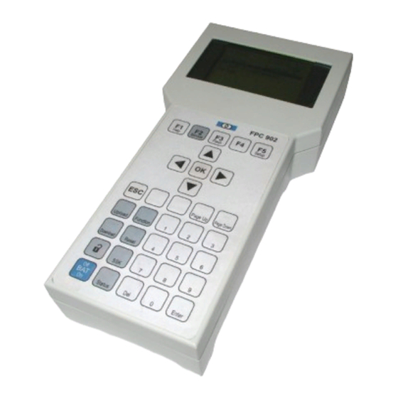
НСТРУКЦИЯ ИСПОЛЬЗОВАНИЯ и ЭКСПЛУАТАЦИИ RECORD 16
П


равильно установленная автоматическая дверь не требует дополнительной настройки или регулировки.
П
ользователь может выбирать необходимый режим работы с помощью клавиш пульта управления.
Режимы работы
- ТОЛЬКО ВЫХОД – дверь открывается только при детекции объекта внутренним радаром. Внешний радар выключен .
- ЗИМНИЙ РЕЖИМ — дверь открывается не полностью, на расстояние установленное инженером при монтаже (меняется программированием)
- АВТОМАТИЧЕСКИЙ РЕЖИМ – дверь открывается при приближении объекта с любой стороны.
- ВСЕГДА ОТКРЫТО – дверь фиксируется в открытом положении.
- ЗАКРЫТО НА ЗАМОК – дверь закрыта на электромеханический замок
(


при полном обесточивании тянуть за кнопку замка под крышкой привода)
Дверь стандартно комплектуется фото датчиками — “лучом безопасности” при нахождении объекта в разрыве лучей дверь останавливается и открывается.
При препятствовании закрытию дверей они при превышении установленного при монтаже усилия останавливаются и начинают открываться.
Дверь стандартно комплектуется резервным аккумулятором.
При отсутствии питания 220 V дверь начинает работать в автономном режиме, при этом начинают мигать по кругу все индикаторы.
В автономном режиме скорость меньше стандартной.
Ресурс автономного режима до 2 часов, в последнем цикле дверь в зависимости от программирования при установке, либо перейдет в режим ВСЕГДА ОТКРЫТО либо в режим ЗАКРЫТО НА ЗАМОК.
При полном отсутствии электропитания Вы можете открыть замок вручную, с помощью зеленой аварийной кнопки .
ДОПОЛНИТЕЛЬНЫЕ УСТРОЙСТВА ЗАЩИТЫ И ПРОТИВО ПОЖАРНОЙ БЕЗОПОСНОСТИ
Оператор RECORD –16 стандартно комплектуется интерфейсом сопряжения с дополнительными устройствами защиты, сигнализации и противопожарной безопасности, для безусловного открытия дверей (даже при отсутствии электропитания) при получении сигнала о пожарной опасности с соответствующей системы сигнализации. Подключение данных систем должно производиться по согласованию сервисного центра RECORD и установщиков соответствующих систем.
ОБСЛУЖИВАНИЕ И ПЕРИОДИЧЕСКАЯ ИНСПЕКЦИЯ
Для многолетней безотказной работы Ваши двери нуждаются в периодическом профилактическом сервисном обслуживании квалифицированными специалистами.
Производитель рекомендует производить два раза в год тест безопасности работы дверей. Необходимо, также содержать в чистоте нижние направляющие дверей.
Направляющие необходимо смазывать силиконовой смазкой или WD-40 каждые 7 дней
ИНСТРУКЦИЯ ПО ЭКСПЛУАТАЦИИ АВТОМАТИЧЕСКИХ ДВЕРЕЙ РЕКОРД (RECORD)
Пользователь может выбирать необходимый режим работы с помощью клавиш пульта управления.
Режимы работы:
1. ТОЛЬКО ВЫХОД – дверь открывается только при детекции объекта внутренним радаром. Внешний радар выключен .
2. ЗИМНИЙ РЕЖИМ — дверь открывается не полностью, на расстояние установленное инженером при монтаже (меняется программированием).
3. АВТОМАТИЧЕСКИЙ РЕЖИМ – дверь открывается при приближении объекта с любой стороны.
4. ВСЕГДА ОТКРЫТО – дверь фиксируется в открытом положении.
5. ЗАКРЫТО НА ЗАМОК – дверь закрыта на электромеханический замок.
( при полном обесточивании тянуть за кнопку замка под крышкой привода)
Дверь стандартно комплектуется фото датчиками — “лучом безопасности” при нахождении объекта в разрыве лучей дверь останавливается и открывается.
При препятствовании закрытию дверей они при превышении установленного при монтаже усилия останавливаются и начинают открываться.
Дверь стандартно комплектуется резервным аккумулятором.
При отсутствии питания 220 V дверь начинает работать в автономном режиме, при этом начинают мигать по кругу все индикаторы.
В автономном режиме скорость меньше стандартной
Ресурс автономного режима до 2 часов, в последнем цикле дверь в зависимости от программирования при установке, либо перейдет в режим ВСЕГДА ОТКРЫТО либо в режим ЗАКРЫТО НА ЗАМОК.
При полном отсутствии электропитания Вы можете открыть замок вручную, с помощью зеленой аварийной кнопки .
ДОПОЛНИТЕЛЬНЫЕ УСТРОЙСТВА ЗАЩИТЫ И ПРОТИВО ПОЖАРНОЙ БЕЗОПОСНОСТИ
Оператор RECORD –16 стандартно комплектуется интерфейсом сопряжения с дополнительными устройствами защиты, сигнализации и противопожарной безопасности, для безусловного открытия дверей (даже при отсутствии электропитания) при получении сигнала о пожарной опасности с соответствующей системы сигнализации. Подключение данных систем должно производиться по согласованию сервисного центра RECORD и установщиков соответствующих систем.
ОБСЛУЖИВАНИЕ И ПЕРИОДИЧЕСКАЯ ИНСПЕКЦИЯ
Для многолетней безотказной работы Ваши двери нуждаются в периодическом профилактическом сервисном обслуживании квалифицированными специалистами.
Производитель рекомендует производить два раза в год тест безопасности работы дверей. Необходимо, также содержать в чистоте нижние направляющие дверей.
Ремонт и сервисное обслуживание в Москве и МО.
Автоматические двери

Автоматические двери
Почему стоит заказывать у нас?
Современные автоматические двери стали обязательным атрибутом торговых и офисных центров, банков, общественных заведений и супермаркетов. Обеспечивая комфортное посещение помещения большому количеству людей, такие устройства прекрасно подчеркивают современные интерьеры и демонстрируют высокий статус компании.
В автоматической двери нет лишних функциональных и декоративных деталей. Только продуманная практичность. Долговечность обеспечивается использованием высококачественных материалов, таких как:
- Алюминий;
- Сталь;
- Закаленное стекло;
- Дерево.
Также при необходимости могут использоваться пуленепробиваемая сталь и бронированное стекло. Широкий выбор материалов, механизмов и дизайнов позволяет реализовать практически любое желание клиента.
Основными преимуществами автоматических дверей являются:
- Удобство для людей всех возрастов, в том числе инвалидов.
- Универсальность. Возможность закрыть проем любой площади. Используются в общественных помещениях разного назначения: магазинах, банках, офисных центрах, ресторанах.
- Долговечность . Стандартная дверь при высокой интенсивности использования быстро изнашивается, в отличие от автоматической.
- Возможность въезда с тележками и колясками.
- Возможность подключения различных систем контроля доступа .
- Дополнительные возможности. Н апример, система автоматических дверей Tormax способна предоставлять информацию о количестве часов работы, циклов открытия, неисправностях, а также останавливаться при возникновении препятствий.
- Независимость от электричества . При выключении электричества включается аварийный аккумулятор.
- Теплосбережение. Ав томатические двери позволяют снизить потери тепла до 20-30%.
- Контроль и безопасность . Система блокируется в случае аварии.
- Экономия площади, поскольку нет необходимости оставлять пространство для открытия двери.
Автоматические двери позволяют подчеркнуть стиль и имидж компании, продемонстрировать лояльность и заботу о клиентах. В «Арвис-Систем» можно заказать различные типы автоматических входных дверей, межкомнатные модели, входные группы нужного размера, выполненные из качественных материалов и проверенных механизмов.
Почему мы?
- Полный комплекс работ , включающий разработку дизайн-проекта, монтаж, настройку и сервисное обслуживание автоматики.
- Только лучше бренды – G EZE, TORMAX и т. д.
- Гарантия – 2 года . Незапятнанную репутацию надежных механизмов подтверждают наши гарантийные обязательства.
- Возможность реализации любых идей, бла годаря наличию большого выбора автоматических дверей. Мы поможем выбрать наиболее подходящее по цене, качеству и стилю решение.
- Сервис в режиме 24/7 – техническое обслуживание и бесплатные консультации.
- Удобные системы расчетов.
- Бесплатная доставка.
Получить бесплатную консультацию можно по тел. +38 095 357 94 94 .
Типы автоматических дверей
К основным типам автоматических дверей относят:
- Раздвижные;
- Распашные;
- Телескопические;
- Карусельные;
- Радиусные.
Ниже мы рассмотрим особенности каждого типа автоматических дверей, чтобы вы могли определиться с наиболее подходящим вариантом.
Как мы работаем?

За дополнительной консультацией обращайтесь:


- Описание
- Технические характеристики
Автоматические телескопические раздвижные двери Record (Швейцария)
Автоматические двери телескопического типа позволяют увеличить ширину прохода, не изменяя размеров проема. Телескопические автоматические двери Record — для ширины прохода до четырех метров.

Раздвижные телескопические двери оптимальны для больших дверных проемов. Это идеальный выбор для ситуаций, когда необходима высокая пропускная способность .
У этой конструкции створки открываются с каждой стороны наезжая одна на другую по принципу телескопа. Есть возможность регулировать ширину открытия, что особенно важно зимой.
Преимущества телескопических дверей:
- возможность расширить проход до 2/3 ширины архитектурного проема;
- быстрое открытие;
- тишина и надежность;
- автономная работа каждого входа.
Компания СІНТЕК предлагает 2-, 3-, 4- 5- створчатые варианты телескопических дверей Record.
В качестве новинки Record предлагает 3-х створчатый односторонний телескоп, а также двухсторонний, т.е. при использовании 6-ти створок одновременно !
Кроме того, вся продукция Record (Швейцария) обладает внушительным рабочим ресурсом, порядка 10-15 лет, что избавляет наших клиентов от забот технического обслуживания и, как следствие, дополнительных расходов.
СВЯЖИТЕСЬ С НАМИ любым удобным для Вас способом и эксперты компании СІНТЕК помогут подобрать подходящее именно для Вашего объекта оборудование.
16 TSA
Ширина прохода А
Для двухстворчатых дверей
Для одностворчатых дверей
Высота прохода G
Рекомендованная максимальная высота
Максимальный вес дверных створок
Для двухстворчатых дверей
Для одностворчатых дверей
Габаритные размеры привода с кожухом
Движение створок (программируется)
Для двухстворчатых дверей
Для одностворчатых дверей
Электрические параметры
Номинальный ток потребления
Номинальная мощность потребления
Мощность потребления в режиме «ожидания»
Основные функции
- «Автоматический»режим с полным открыванием двери
- Автоматический режим с регулируемой шириной прохода («Зимний»режим управления)
- Автоматический режим с односторонним проходом через дверь (режим «Закрытый магазин»)
- Закрывание двери на электромеханический замок с возможностью ручной разблокировки
- Блокировка управлениядверью от несанкционированного доступа к управлению
- Автоматическая отмена«Зимнего» режима при большой интенсивности прохода через дверь
Функции безопасности
- Датчики безопасностипредотвращают закрывание двери в случае нахождения в проеме людей и/или предметов
- Любое препятствие закрываниюдвери приводит к немедленному ее открыванию
- Любое препятствие открываниюдвери приводит к ее немедленной остановке
- Позиция препятствия запоминаетсяи при последующем цикле работы двери движение створок замедляется до позиции препятствия
- При пропадании напряжения питания двери остаются в работоспособном состоянии и работают от аккумуляторов
- При достижении разрядки батареи привод автоматически выполнит функцию, запрограммированную пользователем как «последнюю» для двери (например: «открытое состояние» или «закрытое состояние с запиранием на замок»). При закрытии дверей на замок, всегда есть возможность ручной разблокировки и открытия дверей вручную
- Возможность сопряженияработы привода с системами контроля доступа, охранной/пожарной сигнализации
Установка параметров привода по желанию пользователя
- Индивидуальная скорость движения створоккак при закрывании двери, так и при ее открывании
- Индивидуальное время открытого состояния двери после получения команды на ее открытие
- Выдача сигнала управленияна устройство тепловой завесы
· Индивидуальная ширина прохода в «Зимнем» режиме
Adblock
detector
-
Contents
-
Table of Contents
-
Troubleshooting
-
Bookmarks
Quick Links
User manual record system 20 RED
automatic door systems — this is record!
Translation of the original manual
Related Manuals for Record system 20 RED Series
Summary of Contents for Record system 20 RED Series
- Page 1
User manual record system 20 RED automatic door systems — this is record! Translation of the original manual… -
Page 2: Table Of Contents
Table of contents Table of contents Table of revisions ………………..Safety instructions and regulations …………..Presentation of warning signs ………………….General safety and accident prevention regulations…………..Danger zones ……………………..1.3.1 Security- and surveillance equipment ……………….. 1.3.2 Danger warnings on the product ………………..1.3.3 Reconstructions and changes to the product……………..
- Page 3
Table of contents Manual opening and closing in case of failure (RED)………. Manual opening (without manual unlocking device) …………..Manual closing ……………………..6.2.1 Step 1 ……………………….. 6.2.2 Step 2 ……………………….. Emergency opening of the door (RED) …………… Emergency opening with current supply ………………Emergency opening in case of power failure with auxiliary battery (RED) …….. -
Page 4: Table Of Revisions
Table of revisions Table of revisions Document identification New chapter …………..9 Safety Instructions and Regulations Chapter Sequence Changed ……… 5 Use of the device Note according to IEC 60335-1 2010 changed ….. 6 BAL_SYS20_RED_EN_2V2_REC_102-020110693 4/ 27…
-
Page 5: Safety Instructions And Regulations
Safety instructions and regulations Safety instructions and regulations Presentation of warning signs Various symbols are used in this guide for easier understanding: NOTICE Useful advice and information to ensure correct and efficient workflow of the system. IMPORTANT Specific details which are essential for trouble-free operation of the system. IMPORTANT Important details which must be read for proper function of the system.
-
Page 6: General Safety And Accident Prevention Regulations
Safety instructions and regulations General safety and accident prevention regulations NOTICE This system is not intended to be used by persons (including children from the age of
with limited physical, sensory or mental abilities or with a lack of expe- rience and/or knowledge.
-
Page 7: Danger Zones
Safety instructions and regulations CAUTION Unexpected OPENING / CLOSING / ROTATION • Bruises and contusions from the door wings/apron No persons or objects are allowed in the opening area of the door. No safety devices (sensors) should be removed or disabled. …
-
Page 8: Intended Purpose Of Use
Safety instructions and regulations Intended purpose of use The system is designed exclusively for use as a pedestrian passage. The installation may only occur in dry areas. If there are deviations then proper waterproofing and water drains will be required on- site.
-
Page 9: General Information
General information General information Document identification Name: BAL_SYS20_RED_DE_2V2_REC_102-020110692 Version: V2.2 Article No.: 102-020110692 Date of publication: 03/2019 Application range STA/TSA 20RED/22RED NOTICE System 20 includes the following drives to which these instructions apply. STA/TSA 20 RED or 22 RED Target groups (User) This operating manual is intended for the target groups listed below: ▪…
-
Page 10: Maintenance And Regular Inspection
General information Maintenance and regular inspection Prior to carrying out the first commissioning and if required as well as in accordance with the applica- ble regulations — however at least twice a year – a technical inspection by a skilled service technician or an authorized partner must take place.
- Page 11
General information Function and safety Operator Monthly check Regular maintenance Technical expert 1 × per year, or accord- ing to country specific directives and regula- tions Regular testing (inspec- Technical expert 1 × per year, or accord- tion) ing to country specific directives and regula- tions Regular testing (inspec-… -
Page 12: General Technical Data
General technical data General technical data NOTICE Load capacity for lintel installations The standard guidelines for load capacities on lintel installations can be found in the corresponding chapter NOTICE 3 carriages required for door weight per wing > 90 kg 4 carriages required for door weight per wing >…
-
Page 13: Operating Instructions (Red)
Operating instructions (RED) Operating instructions (RED) Selection of operating modes (RED) The electronic control unit BDE-D is a user-friendly input and output unit to control and customize (op- tional) the door operation. The LCD display with backlight gives information about the door status with symbols and clear text.
-
Page 14: Selection Of Special Functions (Red)
Operating instructions (RED) NOTICE The reduced opening width is also effective with operating modes (One-Way) (Continuously open). Selection of special functions (RED) Function Display Description ▪ Door is closed and locked ▪ 1 keystroke unlocks the door ▪ An opening/closing cycle is performed Single opening ▪…
-
Page 15: Locking The Control Unit With A Key (Option)
Operating instructions (RED) Locking the control unit with a key (option) IMPORTANT Standard EN 16005 requires protection, for the mode selection of operation of pedestrian automatic doors, used as emergency exits so that they may not be inadvertently locked when the building is in use. If a «locked»…
-
Page 16: Self-Test (Redundancy Test) Of Operator
Self-test (redundancy test) of operator Self-test (redundancy test) of operator When a self-test is carried out? In certain conditions, the door automatically performs a so-called «redundancy test», i.e. the door car- ries out a slow opening and closing cycle, thereby checking safety functions. Such function is executed in particular in case of a change of the operating mode as specified below: ▪…
-
Page 17: Manual Opening And Closing In Case Of Failure (Red)
Manual opening and closing in case of failure (RED) Manual opening and closing in case of failure (RED) Manual opening (without manual unlocking device) Initial situation: The door is disconnected from the mains and is blocked in the closed and locked position. ▪…
-
Page 18: Manual Closing
Manual opening and closing in case of failure (RED) Manual closing Initial situation: Electric power is supplied. The door remains blocked in open position. NOTICE According to the kind of failure, the procedure for a manual closing will be differ- ent.
- Page 19
Manual opening and closing in case of failure (RED) ▪ Besides, unscrew both accumulator (storage battery) fuses. ▪ The accumulator is located under the casing. ▪ Slide the door by hand into the closed posi- tion. ▪ Turn the unlocking lever clockwise and hold it in this position so that the door can close completely. -
Page 20: Emergency Opening Of The Door (Red)
Emergency opening of the door (RED) Emergency opening of the door (RED) Emergency opening with current supply By activating the emergency opening switch (optional), which must be placed beside the installation, the door will open as long as the operating mode Locked has not been selected. In this operating mode the door will remain locked.
-
Page 21: Closing And Locking The Door
Emergency opening of the door (RED) 7.3.3 Closing and locking the door ▪ Activate the emergency opening ▪ This causes the locking device to be unlocked ▪ Slide the door manually into the closed position ▪ Keep the door leafs in the closed position ▪…
-
Page 22: Behaviour In Event Of Faults
Behavior in event of faults Behavior in event of faults In the event of an irregularity or malfunction, different displays are shown depending on the control unit connected. NOTICE If the door performs a slow opening or closing movement, this can indicate a deliberate automatic redundancy test.
-
Page 23: Control Unit Bde-D Does Not React
Behavior in event of faults Control unit BDE-D does not react If the control panel does not react when the keys are pressed or if no message appears on the dis- play, a reset of the control panel could eliminate the problem. Proceed as follows: RESET HARDWARE BDE-D Press E key >…
-
Page 24: Functions And Safety Check
Functions and safety check Functions and safety check General remarks According to the legal provision in force, the operating entity of the automatic door is responsible for its maintenance and for the user’s safety, as soon as the installation has been handed over. The regular inspection of single elements by the operator requires little time investment and reinforces the prevention of accidents caused by an inappropriate use of the door.
-
Page 25: Monthly Inspection Work To Be Carried Out By The Operating Company
Functions and safety check Monthly inspection work to be carried out by the operating company The monthly inspection and maintenance of individual elements by the operating company requires little time and serves the reliable function, increased service life and operational safety of the system. Test / inspection Procedure Expected result…
- Page 26
Functions and safety check Test / inspection Procedure Expected result ▪ Set the door to manual oper- ▪ The door leaf must be Continuous floor guide (instead ation (see chapter «Selecting properly guided of punctual door leaf guide) special functions») ▪… -
Page 27: Recommended And Planned Spare- And Wear Parts
Recommended and planned spare- and wear parts Recommended and planned spare- and wear parts Spare part/Wear part Interval * CO48 (Silicon or Rubber) 1 year * Pulley CO48 3 years Battery 3 years Antistatic brush 3 years Door leaf guide (plastic) 3 years Guiding pad 3 years…
- Page 28
Contact ➔ record UK limited Head Office: Unit D, 9 Watt Place — Hamilton International Park — Blantyre — G72 0AH — UK Central Office: Batley Business Centre — Unit 40 — Annexe 2 — Technology Drive — Batley — Wf17 6ER — UK Southern Office: 17 Invincible Road — Farnborough — Gu14 7QU — UK tel.: +44 1698 376411 — fax: +44 1698 376422 -…
-
Contents
-
Table of Contents
-
Troubleshooting
-
Bookmarks
Quick Links
User manual record system 20 RED
automatic door systems — this is record!
Translation of the original manual
Related Manuals for Record system 20 RED Series
Summary of Contents for Record system 20 RED Series
- Page 1
User manual record system 20 RED automatic door systems — this is record! Translation of the original manual… -
Page 2: Table Of Contents
Table of contents Table of contents Table of revisions ………………..Safety instructions and regulations …………..Presentation of warning signs ………………….General safety and accident prevention regulations…………..Danger zones ……………………..1.3.1 Security- and surveillance equipment ……………….. 1.3.2 Danger warnings on the product ………………..1.3.3 Reconstructions and changes to the product……………..
- Page 3
Table of contents Manual opening and closing in case of failure (RED)………. Manual opening (without manual unlocking device) …………..Manual closing ……………………..6.2.1 Step 1 ……………………….. 6.2.2 Step 2 ……………………….. Emergency opening of the door (RED) …………… Emergency opening with current supply ………………Emergency opening in case of power failure with auxiliary battery (RED) …….. -
Page 4: Table Of Revisions
Table of revisions Table of revisions Document identification New chapter …………..9 Safety Instructions and Regulations Chapter Sequence Changed ……… 5 Use of the device Note according to IEC 60335-1 2010 changed ….. 6 BAL_SYS20_RED_EN_2V2_REC_102-020110693 4/ 27…
-
Page 5: Safety Instructions And Regulations
Safety instructions and regulations Safety instructions and regulations Presentation of warning signs Various symbols are used in this guide for easier understanding: NOTICE Useful advice and information to ensure correct and efficient workflow of the system. IMPORTANT Specific details which are essential for trouble-free operation of the system. IMPORTANT Important details which must be read for proper function of the system.
-
Page 6: General Safety And Accident Prevention Regulations
Safety instructions and regulations General safety and accident prevention regulations NOTICE This system is not intended to be used by persons (including children from the age of
with limited physical, sensory or mental abilities or with a lack of expe- rience and/or knowledge.
-
Page 7: Danger Zones
Safety instructions and regulations CAUTION Unexpected OPENING / CLOSING / ROTATION • Bruises and contusions from the door wings/apron No persons or objects are allowed in the opening area of the door. No safety devices (sensors) should be removed or disabled. …
-
Page 8: Intended Purpose Of Use
Safety instructions and regulations Intended purpose of use The system is designed exclusively for use as a pedestrian passage. The installation may only occur in dry areas. If there are deviations then proper waterproofing and water drains will be required on- site.
-
Page 9: General Information
General information General information Document identification Name: BAL_SYS20_RED_DE_2V2_REC_102-020110692 Version: V2.2 Article No.: 102-020110692 Date of publication: 03/2019 Application range STA/TSA 20RED/22RED NOTICE System 20 includes the following drives to which these instructions apply. STA/TSA 20 RED or 22 RED Target groups (User) This operating manual is intended for the target groups listed below: ▪…
-
Page 10: Maintenance And Regular Inspection
General information Maintenance and regular inspection Prior to carrying out the first commissioning and if required as well as in accordance with the applica- ble regulations — however at least twice a year – a technical inspection by a skilled service technician or an authorized partner must take place.
- Page 11
General information Function and safety Operator Monthly check Regular maintenance Technical expert 1 × per year, or accord- ing to country specific directives and regula- tions Regular testing (inspec- Technical expert 1 × per year, or accord- tion) ing to country specific directives and regula- tions Regular testing (inspec-… -
Page 12: General Technical Data
General technical data General technical data NOTICE Load capacity for lintel installations The standard guidelines for load capacities on lintel installations can be found in the corresponding chapter NOTICE 3 carriages required for door weight per wing > 90 kg 4 carriages required for door weight per wing >…
-
Page 13: Operating Instructions (Red)
Operating instructions (RED) Operating instructions (RED) Selection of operating modes (RED) The electronic control unit BDE-D is a user-friendly input and output unit to control and customize (op- tional) the door operation. The LCD display with backlight gives information about the door status with symbols and clear text.
-
Page 14: Selection Of Special Functions (Red)
Operating instructions (RED) NOTICE The reduced opening width is also effective with operating modes (One-Way) (Continuously open). Selection of special functions (RED) Function Display Description ▪ Door is closed and locked ▪ 1 keystroke unlocks the door ▪ An opening/closing cycle is performed Single opening ▪…
-
Page 15: Locking The Control Unit With A Key (Option)
Operating instructions (RED) Locking the control unit with a key (option) IMPORTANT Standard EN 16005 requires protection, for the mode selection of operation of pedestrian automatic doors, used as emergency exits so that they may not be inadvertently locked when the building is in use. If a «locked»…
-
Page 16: Self-Test (Redundancy Test) Of Operator
Self-test (redundancy test) of operator Self-test (redundancy test) of operator When a self-test is carried out? In certain conditions, the door automatically performs a so-called «redundancy test», i.e. the door car- ries out a slow opening and closing cycle, thereby checking safety functions. Such function is executed in particular in case of a change of the operating mode as specified below: ▪…
-
Page 17: Manual Opening And Closing In Case Of Failure (Red)
Manual opening and closing in case of failure (RED) Manual opening and closing in case of failure (RED) Manual opening (without manual unlocking device) Initial situation: The door is disconnected from the mains and is blocked in the closed and locked position. ▪…
-
Page 18: Manual Closing
Manual opening and closing in case of failure (RED) Manual closing Initial situation: Electric power is supplied. The door remains blocked in open position. NOTICE According to the kind of failure, the procedure for a manual closing will be differ- ent.
- Page 19
Manual opening and closing in case of failure (RED) ▪ Besides, unscrew both accumulator (storage battery) fuses. ▪ The accumulator is located under the casing. ▪ Slide the door by hand into the closed posi- tion. ▪ Turn the unlocking lever clockwise and hold it in this position so that the door can close completely. -
Page 20: Emergency Opening Of The Door (Red)
Emergency opening of the door (RED) Emergency opening of the door (RED) Emergency opening with current supply By activating the emergency opening switch (optional), which must be placed beside the installation, the door will open as long as the operating mode Locked has not been selected. In this operating mode the door will remain locked.
-
Page 21: Closing And Locking The Door
Emergency opening of the door (RED) 7.3.3 Closing and locking the door ▪ Activate the emergency opening ▪ This causes the locking device to be unlocked ▪ Slide the door manually into the closed position ▪ Keep the door leafs in the closed position ▪…
-
Page 22: Behaviour In Event Of Faults
Behavior in event of faults Behavior in event of faults In the event of an irregularity or malfunction, different displays are shown depending on the control unit connected. NOTICE If the door performs a slow opening or closing movement, this can indicate a deliberate automatic redundancy test.
-
Page 23: Control Unit Bde-D Does Not React
Behavior in event of faults Control unit BDE-D does not react If the control panel does not react when the keys are pressed or if no message appears on the dis- play, a reset of the control panel could eliminate the problem. Proceed as follows: RESET HARDWARE BDE-D Press E key >…
-
Page 24: Functions And Safety Check
Functions and safety check Functions and safety check General remarks According to the legal provision in force, the operating entity of the automatic door is responsible for its maintenance and for the user’s safety, as soon as the installation has been handed over. The regular inspection of single elements by the operator requires little time investment and reinforces the prevention of accidents caused by an inappropriate use of the door.
-
Page 25: Monthly Inspection Work To Be Carried Out By The Operating Company
Functions and safety check Monthly inspection work to be carried out by the operating company The monthly inspection and maintenance of individual elements by the operating company requires little time and serves the reliable function, increased service life and operational safety of the system. Test / inspection Procedure Expected result…
- Page 26
Functions and safety check Test / inspection Procedure Expected result ▪ Set the door to manual oper- ▪ The door leaf must be Continuous floor guide (instead ation (see chapter «Selecting properly guided of punctual door leaf guide) special functions») ▪… -
Page 27: Recommended And Planned Spare- And Wear Parts
Recommended and planned spare- and wear parts Recommended and planned spare- and wear parts Spare part/Wear part Interval * CO48 (Silicon or Rubber) 1 year * Pulley CO48 3 years Battery 3 years Antistatic brush 3 years Door leaf guide (plastic) 3 years Guiding pad 3 years…
- Page 28
Contact ➔ record UK limited Head Office: Unit D, 9 Watt Place — Hamilton International Park — Blantyre — G72 0AH — UK Central Office: Batley Business Centre — Unit 40 — Annexe 2 — Technology Drive — Batley — Wf17 6ER — UK Southern Office: 17 Invincible Road — Farnborough — Gu14 7QU — UK tel.: +44 1698 376411 — fax: +44 1698 376422 -…
Автоматические дверные системы
Автоматические дверные системы – это record!
Более 60 лет мы проектируем, разрабатываем, производим, продаем, устанавливаем и обслуживаем автоматические дверные системы. За это время мы накопили огромное количество знаний, с помощью которых можно получить многочисленные решения.
В наших автоматические дверных системах отражены эти знания во всех аспектах. Это позволяет создавать широкий выбор моделей и вариантов исполнения, способных удовлетворить требования для практически любой входной группы.
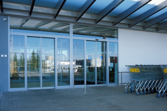


Типичный record!
Будь это функциональное применение, такое как пути эвакуации, пожарная безопасность или разделение двух климатических зон, или же повышение удобства входа за счет обеспечения без барьерного доступа в домах престарелых, или обеспечение бесконтактного доступа в операционные, или открытие дверей в качестве приветственного жеста в универмагах; будь то защитная блокировка в защищенных зонах, разрешающих только односторонний доступ или выступая в качестве обычной, телескопической, вращающейся или радиусной раздвижной двери: record делает все это возможным!
record – автоматические раздвижные двери
Несмотря на то, что наши раздвижные двери могут выглядеть по-разному, все они характеризуются множеством функций, которые в совокупности мы называем «типичный record». Для вас, для клиентов, их ключевой особенностью является заметная плавность хода, которая является главным результатом наших разработок и инженерных навыков. Однако общее впечатление становится благоприятным только тогда, когда все элементы двери работают гармонично и движутся слаженно. Вот где опыт наших разработчиков проявляется уже более 60 лет.
Автоматические раздвижные двери — основа нашего успеха. Раздвижные двери, это не только двери, которые предпочитают наши клиенты, но и самый универсальный вариант. Начиная с множества типов остекления, разнообразия и видов обработки поверхности двери и профилей, до вариантов с цельностеклянными конструкциями. Разнообразие конструкций является вызовом для любого творческого потенциала.
record – приводы распашных дверей
record DFA 127 — это универсальная система привода для автоматизации распашных дверей. Она отличается сложной технологией, компактным дизайном и невероятной плавностью работы. Наш взвешенный подход к широкому спектру задач делает привод универсальным для всех дверей.
record – автоматические револьверные двери
Револьверные двери, несомненно, являются наиболее заметной частью нашего портфолио. Это не только из-за их внушительных размеров, но и из-за их уникальных особенностей, которые позволяют архитекторам менять форму и конструкцию дверей, применяя новые и значительные изменения.
record – автоматические складные двери и входные системы
Для наших складных дверей и их вариантов используют иной принцип конструкции автоматических дверей.
record – особое применение
record также предлагает решения для аварийных выходов и конструкции для узкоспециализированных задач особого применения.
Pedestrian Sliding Door Operator
record 16 STA
record 16 STA-UL
Manual
E
1 Table of contents ……………………………………………………………………………………………………2
2 General remarks……………………………………………………………………………………………………..4
3 Safety instructions………………………………………………………………………………………………….5
4 Technical data & operating conditions……………………………………………………………………..8
5 Elevation and plan views…………………………………………………………………………………………9
6 Preparation for installation…………………………………………………………………………………….10
7 Installation instructions…………………………………………………………………………………………16
8 Commissioning and final work ………………………………………………………………………………35
9 Operating instructions…………………………………………………………………………………………..40
10 Status and fault signals………………………………………………………………………………………44
11 Abbreviations …………………………………………………………………………………………………….49
12 Cable Routing…………………………………………………………………………………………………….50
13 Wiring diagram…………………………………………………………………………………………………..51
14 Addresses of subsididaries ………………………………………………………………………………..53
Ó Copyright by agtatec ag, CH-8320 Fehraltorf
agtatec ag
Allmendstraße 24
CH-8320 Fehraltorf
Switzerland
Phone
Fax
+41 1 954 91 91
+41 1 954 92 00
part no. : 16.760; Rev. B
Page 2 / 53 Chapter : Table of contents
1 Table of contents
1 Table of contents ……………………………………………………………………………………………………2
2 General remarks……………………………………………………………………………………………………..4
2.1 Symbols ……………………………………………………………………………………………………………………………….. 4
3 Safety instructions………………………………………………………………………………………………….5
3.1 Use for the intended purpose ………………………………………………………………………………………………….. 5
3.2 General safety and accident prevention regulations……………………………………………………………………. 5
3.3 Safety and accident prevention regulations for UL 325 installations ……………………………………………… 6
3.4 Final adjustments and tests on site for proper operation :……………………………………………………………. 7
4 Technical data & operating conditions……………………………………………………………………..8
5 Elevation and plan views…………………………………………………………………………………………9
6 Preparation for installation…………………………………………………………………………………….10
6.1 Preliminary work in workshop ………………………………………………………………………………………………… 10
6.2 Drive module……………………………………………………………………………………………………………………….. 10
6.3 Completing drive module with options …………………………………………………………………………………….. 13
6.4 Fitting battery BAT ……………………………………………………………………………………………………………….. 13
6.5 Fitting lock VRR …………………………………………………………………………………………………………………… 14
6.6 Fitting HEI / HEA………………………………………………………………………………………………………………….. 14
6.7 Testing drive module ……………………………………………………………………………………………………………. 14
6.8 Preliminary clarification on site ………………………………………………………………………………………………. 15
6.9 Determining type of installation………………………………………………………………………………………………. 15
7 Installation instructions…………………………………………………………………………………………16
7.1 Start of installation using cladding profile ………………………………………………………………………………… 16
7.2 Fixing the cladding profile P1307……………………………………………………………………………………………. 16
7.2.1
Type of installation: self-supporting ……………………………………………………………………………… 16
7.2.2
Type of installation: lintel installation ……………………………………………………………………………. 17
7.3 Installation of side screens and/or wall connection profile………………………………………………………….. 18
7.4 Inserting track support section……………………………………………………………………………………………….. 20
7.5 Inserting fanlight if provided…………………………………………………………………………………………………… 21
7.6 Inserting infill profile P1309……………………………………………………………………………………………………. 21
7.7 Horizontal sealing profile and strip brush…………………………………………………………………………………. 22
7.8 Fitting ELS ………………………………………………………………………………………………………………………….. 22
7.9 Fitting door leaf guides …………………………………………………………………………………………………………. 23
7.10 Starting installation without cladding profile (without side screen)……………………………………………… 24
7.11 Inserting track profile ………………………………………………………………………………………………………….. 25
7.12 Inserting carriage ……………………………………………………………………………………………………………….. 26
7.13 Setting end stops ……………………………………………………………………………………………………………….. 27
7.14 External radar ……………………………………………………………………………………………………………………. 27
7.15 Hanging door leaves…………………………………………………………………………………………………………… 27
7.16 Adjusting door leaves …………………………………………………………………………………………………………. 28
7.17 Fixing end stops…………………………………………………………………………………………………………………. 30
7.18 Attaching drive module ……………………………………………………………………………………………………….. 31
M6 x 10mm and tongue nuts………………………………………………………………………………………………… 33
7.19 Checking toothed belt tension ……………………………………………………………………………………………… 33
7.20 Checking door leaves by hand …………………………………………………………………………………………….. 33
7.21 Options (if not already completed as preliminary work in workshop) …………………………………………. 33
7.22 Cable layout ………………………………………………………………………………………………………………………. 34
7.23 Connecting electrical units…………………………………………………………………………………………………… 34
7.24 Protection wings ………………………………………………………………………………………………………………… 34
7.25 Final mechanical test ………………………………………………………………………………………………………….. 34
8 Commissioning and final work ………………………………………………………………………………35
8.1 Preparation …………………………………………………………………………………………………………………………. 35
8.2 Checking settings ………………………………………………………………………………………………………………… 35
8.3 Switching on power supply and calibration run…………………………………………………………………………. 35
8.4 Checking LED’s on the STG………………………………………………………………………………………………….. 36
8.5 Checking BDE functions and actuating devices ……………………………………………………………………….. 36
8.6 Programming door speeds and hold-open times………………………………………………………………………. 37
Manual record 16 STA / 16 STA-UL part no. : 16.760; Rev. B
Chapter : Table of contents Page 3 / 53
8.7 Configuration of specific customer settings ……………………………………………………………………………… 37
8.7.1
Configuration for UL 325 installations…………………………………………………………………………… 37
8.8 Checking safety …………………………………………………………………………………………………………………… 37
8.9 Checking automatic reverse ………………………………………………………………………………………………….. 37
8.10 Checking BAT functions ……………………………………………………………………………………………………… 37
8.11 Casing………………………………………………………………………………………………………………………………. 38
8.12 Casing version with suspended ceiling………………………………………………………………………………….. 39
8.13 Fitting internal radar……………………………………………………………………………………………………………. 39
8.14 Handing over to customer……………………………………………………………………………………………………. 39
9 Operating instructions…………………………………………………………………………………………..40
9.1 Controls on STG 16 ……………………………………………………………………………………………………………… 40
9.1.1
General:…………………………………………………………………………………………………………………… 40
9.1.2
Jumpers:………………………………………………………………………………………………………………….. 40
9.1.3
LED’s (left to right):……………………………………………………………………………………………………. 40
9.1.4
Key:…………………………………………………………………………………………………………………………. 40
9.2 Functions of electronic BDE-E……………………………………………………………………………………………….. 41
9.2.1
General:…………………………………………………………………………………………………………………… 41
9.2.2
1 st
level (operating modes) …………………………………………………………………………………………. 41
9.2.3
Key functions: …………………………………………………………………………………………………………… 41
9.2.4
2 nd
level (control lock) ………………………………………………………………………………………………… 41
9.2.5
3 rd
level (programming level) ………………………………………………………………………………………. 42
9.3 Functions of mechanical BDE-M ……………………………………………………………………………………………. 43
9.3.1
General:…………………………………………………………………………………………………………………… 43
9.3.2
Modes of operation……………………………………………………………………………………………………. 43
9.3.3
Reset key…………………………………………………………………………………………………………………. 43
10 Status and fault signals………………………………………………………………………………………44
11 Abbreviations …………………………………………………………………………………………………….49
12 Cable Routing…………………………………………………………………………………………………….50
13 Wiring diagram…………………………………………………………………………………………………..51
14 Addresses of subsididaries ………………………………………………………………………………..53
F i i l l e N a m e :
:
M a n u a l l
S T A 1 6 U L .
.
d o c 19.07.2002 07:18
Manual record 16 STA / 16 STA-UL part no. : 16.760; Rev. B
Page 4 / 53 Chapter : General remarks
2 General remarks
This manual is intended for qualified, trained and authorised installers of the record
16 STA / record 16 STA-UL pedestrian sliding door operator.
The manual describes the correct installation and commissioning procedure.
The product is subject to technical modification. There can therefore be differences between the product and the manual.
Product designation: Automatic pedestrian sliding door operator
Product name:
record 16 STA / record 16 STA-UL
2.1 Symbols
Various symbols are used in this manual for simplification:
Note
Especially useful details concerning installation
Special details indispensable for satisfactory operation of the system
Caution
Danger
Details for the prevention of damage to persons and material
Manual record 16 STA / 16 STA-UL part no. : 16.760; Rev. B
Chapter : Safety instructions Page 5 / 53
3 Safety instructions
The record 16 STA / record 16 STA-UL pedestrian sliding door operator has been constructed in accordance with the latest state of the art and the recognised technical safety regulations, including limiting of forces and speeds. Nevertheless, danger can arise for the user if not used as intended.
Installation, maintenance and repairs to the record 16 STA / record 16
STA-UL pedestrian sliding door operator must only be performed by qualified, trained and authorised personnel (technicians).
3.1 Use for the intended purpose
The record 16 STA / record 16 STA-UL pedestrian sliding door operator is designed exclusively for normal service with automatic pedestrian sliding doors and must be installed indoors.
Any other application or use beyond this purpose is not considered to be the use for the intended purpose. The manufacturer bears no liability for any resulting damage; the installer and/or end user alone shall bear the responsibility.
Use for the intended purpose also includes observation of the operating conditions specified by the manufacturer, in addition to regular care, maintenance and repair.
Unauthorised modifications to the pedestrian sliding door operator and/o r its installation exclude all liability of the manufacturer for resulting damage.
3.2 General safety and accident prevention regulations
No safety devices (sensors) may be dismantled or placed out of service.
No persons or objects must be present in the opening area/path of the sliding door, in order to avoid crushing and cutting.
The automatic pedestrian sliding door operator is not intended to be disconnected from the mains at night!
Manual record 16 STA / 16 STA-UL part no. : 16.760; Rev. B
Page 6 / 53 Chapter : Safety instructions
3.3 Safety and accident prevention instruction for installations in compliance with UL325
Before applying the mains voltage to the power supply the installer has to ensure, that the mains voltage selector switch on the power supply NET 16-UL is switched to the correct position (115V / 230V).
The mains power connection has to be done via the mains power cord, provided with the pedestrian sliding door operator. Proper grounding has to be applied. Only permanent wiring is allowed with this pedestrian sliding door operator.
Wherever 230V only is mentioned throughout this manual, either 115V or 230V is meant, according to the applied mains voltage in the country it is to be installed.
If any electrical unit (photoelectric sensor, radar, control unit, control panel,…) is not mounted within the existing construction of the automatic sliding door installation (e.g. on an adjacent wall) the installer shall protect the cabling from any damage and shall prevent any stress on their connections by proper means. The local installation codes have always to be followed.
WARNING : To avoid risk of electric shock, disconnect mains power (115 / 230V) before servicing.
The delivered red label with the above text has to be placed within the cover above the
NET 16-UL module in such a manner, that it be seen as soon as the cover is opened.
DANGER : The edges of the cut profiles may be sharp. Be careful so as to avoid injury.
WARNING : The installer shall minimize the sharp edges at each profile, especially at the end of the profiles, where the side covers are placed.
NOTE :The installer must visually inspect the pedestrian sliding door operator for sharp edges and eliminate them before completing the installation.
WARNING : Caution, the pedestrian sliding door operator contains moving parts. Be careful, after having opened the cover.
WARNING : to reduce risk of injury to persons, use this operator only with sliding pedestrian doors for residential, commercial or industrial use.
WARNING : Use copper conductors only for any wiring on the pedestrian sliding door operator installation.
WARNING : For continued protection against fire, replace any fuse only with the same type and rating.
Manual record 16 STA / 16 STA-UL part no. : 16.760; Rev. B
Chapter : Safety instructions Page 7 / 53
If the pedestrian sliding door operator is used without a radar sensor to be opened, and a switch is used instead, the switch is to be installed in a location from which operation of the door can be observed by the person operating the switch.
The glazing material in both fixed and sliding panels of a sliding door shall comply with the requirements in the Safety Performance Specifications and Methods of Test within the standard ANSI Z97.1-1984 Safety Glazing Material Used in Buildings. (chapter
29.5 of UL 325)
WARNING : The correct behaviour of the door according to the programmed parameters via the BDE must be verified during commissioning.
3.4 Final adjustments and tests on site for proper operation for compliance with UL325 :
1. Check that all tasks defined in chapter
8 Commissioning and final work
have be carried out properly.
2. Check that the door may be opened manually without power applied to the unit.
3. Remove mains power supply and battery connection and check, that the door may be opened manually with a force not greater than 222.4N (50 lbf).
(chapter 29.3.2 of UL
325)
4. Check that the door does not develop kinetic energy in excess of 9.49J (7 ft-lbf).
(chapter 29.4.1 of UL 325)
5. Check that the door does not require a force greater than 133.4N (30 lbf) applied in either direction to prevent the door from closing.
(chapter 29.4.1 of UL 325)
6. Check, that one photoelectric sensor is installed in a height between 150 and 300mm.
7. Check with a white vertical surface (305 by 152mm), that the photoelectric sensor is working correctly at a total of 5 different locations including a distance of 25.4mm from each end.
(chapter 35.2 of UL 325)
8. Check that the mains power field wired connections are located inside the enclosure of the operator.
Manual record 16 STA / 16 STA-UL part no. : 16.760; Rev. B
Page 8 / 53 Chapter : Technical data & operating conditions
4 Technical data & operating conditions
Opening widths A
·
D-STA
·
E-STA
Clear passage height G
·
Recommended maximum value
Environmental conditions
·
Temperature range
·
Humidity range
800 — 3’000 mm
800 — 3’000 mm
3’000 mm
Total door leaf weights
(max. 67 kg per carriage))
Standard operator :
·
D-STA
·
E-STA max. 2 x 120 kg max. 1 x 200 kg
Heavy duty operator DUO (two motors) :
·
D-STA
·
E-STA max. 2 x 200 kg max. 1 x 250 kg
Dimensions, incl. internal cover
(see general plans)
·
Height
·
Depth
200 mm
160 mm
Door movements
(with a door leaf weight of 75% of maximum weight)
·
Door opening speed (D-STA)
·
Door opening speed (E-STA)
0,7 m opening width in 1,0 sec.
0,7 m opening width in 1,5 sec.
Standard module
Module length 1920 mm:
·
D-STA 800 — 2’800 mm
Versions of special modules, dependent on A-dimension
·
D-STA see point 6.2
·
E-STA see point 6.2
Power supply data
·
Mains voltage (NET 16-UL)
·
Mains frequency
·
Power rating
·
Fuse protection
115/230V
(with mains voltage selector switch)
50 … 60 Hz
200 W
2.5 AT slow-acting
-15° to +50° C up to 85% rel. humidity, non-thawing
Manual record 16 STA / 16 STA-UL part no. : 16.760; Rev. B
Chapter : Elevation and plan views
5 Elevation and plan views
Page 9 / 53
refer also to corresponding general plans
Manual record 16 STA / 16 STA-UL part no. : 16.760; Rev. B
Page 10 / 53 Chapter : Preparation for installation
6 Preparation for installation
6.1 Preliminary work in workshop
·
Prepare material according to preparation list
·
Cut profiles to length and treat surfaces
·
Finish door leaves and side screens and protective screens if necessary according to relevant installation drawings
6.2 Drive module
D-STA / D-TSA
Lock the screws with THREE-BOND. opening widths
A =
800 – 925
926 — 2800
2801 — 3000 module support
L =
1920
1920
2320
F-dimension
F =
1950 fix
2A + 100
2A + 100
1200 — 1320
1321 – 2800
2801 – 3640
3641 – 4000
1920
1920
2320
2700
Version of special modules
2180 fix
1,5A + 200
1,5A + 200
1,5A + 200
D-STA
ATE ßà UMR
B =
1550
1550
1950
D-TSA
1550
1550
1950
2330 door travel
FW =
470
1400
1500
660
1400
1820
2000 slidebar gear belt length
016.000.066 2x 1616
016.000.066 2x 1616
016.000.019 2x 2016
016.000.066 2x 1616
016.000.066 2x 1616
016.000.019 2x 2016
016.000.019 2x 2396 opening widths
A =
800 – 925
1200 – 1320 module support
L =
1670
1670
F-dimension
F =
2A + 100
1,5A + 200
D-STA
ATE ßà UMR
B =
1420
D-TSA
1420 door travel
FW =
470
660 slidebar gear belt length
016.000.008 2x 1488
016.000.008 2x 1488
Manual record 16 STA / 16 STA-UL part no. : 16.760; Rev. B
Chapter : Preparation for installation
E-STA-L / E-TSA-L
Page 11 / 53
Lock the screws with THREE-BOND.
E-STA-L (slidebar 016.000.067) opening widths
A = module support
L =
F-dimension
F =
ATE ßà UMR
B =
NET ßà STD
D =
STD ßà UMR
E =
800 – 905
906 – 1190
1191 – 1760
1761 – 2900
2901 – 3000
1830
1830
2400
3540
3640
1860 fix
2A + 50
2A + 50
2A + 50
1318
1318
1888
3028
8
8
240
400
2A + 50 3128 400
1860 fix
E-TSA-L (slidebar 016.000.067)
1318 8
94
94
94
598
698
800 – 1173
1174 – 1190
1191 – 1216
1217 – 1257
1258 – 1320
1321 – 1415
1416 – 1559
1560 – 1776
1777 – 2102
2103 – 2592
2593 — 3000
1830
1830
1855
1895
1957
2051
2194
2410
2735
3224
3650
1,5A + 100
1,5A + 100
1,5A + 100
1,5A + 100
1,5A + 100
1,5A + 100
1,5A + 100
1,5A + 100
1,5A + 100
1,5A + 100
Version of special modules
1318
1343
1383
1445
1539
1682
11898
2223
2712
3138
8
8
8
8
8
8
240
240
400
400
94
94
94
282
708
94
94
94
94
94
94 door travel
FW =
905
1190
1760
2900
3000
1173
1190
1216
1257
1320
1415
1559
1776
2102
2592
3000 gear belt length
2806
2806
3946
6226
6426
2806
2806
2856
2936
3060
3248
3534
3966
4616
5594
6446 opening widths
A =
800 – 1105
825 — 1155
1065 – 1105
1095 — 1155 module support
L =
1620
1670
1620
1670
E-STA-L (slidebar 016.000.049)
F-dimension
F =
ATE ßà UMR
B =
NET ßà STD
D =
STD ßà UMR
E =
2A + 50 1235 8 74
74 2A + 50 1285 8
E-TSA-L (slidebar 016.000.049)
1,5A + 100 1235 8
1,5A + 100 1285 8
74
74 door travel
FW =
1105
1155
1105
1155 gear belt length
2640
2740
2640
2740
Manual record 16 STA / 16 STA-UL part no. : 16.760; Rev. B
Page 12 / 53 Chapter : Preparation for installation
E-STA-R / E-TSA-R
Lock the screws with THREE-BOND.
opening widths
A = module support
L =
E-STA-R (slidebar 016.000.067)
F-dimension
F =
ATE ßà UMR
B =
NET ßà STD
D =
STD ßà UMR
E =
800 – 905
906 – 1190
1191 – 1760
1761 – 2900
2901 – 3000
1830
1830
2400
3540
3640
1860 fix
2A + 50
2A + 50
1318
1318
1888
8
8
240
2A + 50
2A + 50
3028
3128
400
400
1860 fix
E-TSA-R (slidebar 016.000.067)
1318 8
94
94
94
598
698
800 – 1173
1174 – 1190
1191 – 1216
1217 – 1257
1258 – 1320
1321 – 1415
1416 – 1559
1560 – 1776
1777 – 2102
2103 – 2592
2593 — 3000
1830
1830
1855
1895
1957
2051
2194
2410
2735
3224
3650
1,5A + 100
1,5A + 100
1,5A + 100
1,5A + 100
1,5A + 100
1,5A + 100
1,5A + 100
1,5A + 100
1,5A + 100
1,5A + 100
Version of special modules
1318
1343
1383
1445
1539
1682
11898
2223
2712
3138
8
8
240
240
400
400
8
8
8
8
94
94
94
94
94
94
94
94
94
282
708 door travel
FW =
905
1190
1760
2900
3000
1173
1190
1216
1257
1320
1415
1559
1776
2102
2592
3000 gear belt length
2806
2806
3946
6226
6426
2806
2806
2856
2936
3060
3248
3534
3966
4616
5594
6446 opening widths
A =
800 – 1105
825 — 1155
1065 – 1105
1095 — 1155 module support
L =
1620
1670
1620
1670
E-STA-R (slidebar 016.000.049)
F-dimension
F =
ATE ßà UMR
B =
NET ßà STD
D =
STD ßà UMR
E =
2A + 50
2A + 50
E-TSA-R (slidebar 016.000.049)
1,5A + 100 1235 8
1,5A + 100
1235
1285
1285
8
8
8
19
32
19
32 door travel
FW =
1105
1155
1105
1155 gear belt length
2615
2715
2615
2715
Manual record 16 STA / 16 STA-UL part no. : 16.760; Rev. B
Chapter : Preparation for installation Page 13 / 53
6.3 Completing drive module with options
Finish or complete drive module with options such as BAT, VRR, etc.
Options can also be fitted directly at the place of installation
6.4 Fitting battery BAT
1. System without power
2. Fitting according to diagram
3. The BAT is fitted in the header, or externally with connection if there is no space
(conductor length max. 10 m)
4. Changeover jumper J13 on STG if necessary
(from „without BAT“ to „with BAT“)
Manual record 16 STA / 16 STA-UL part no. : 16.760; Rev. B
Page 14 / 53 Chapter : Preparation for installation
6.5 Fitting lock VRR
6.6 Fitting HEI / HEA
6.7 Testing drive module
Loose slidebars must not touch anywhere!
Manual record 16 STA / 16 STA-UL part no. : 16.760; Rev. B
Chapter : Preparation for installation
6.8 Preliminary clarification on site
·
Check clear width and passage height on installation drawings
Page 15 / 53
clear width metre check
·
Check work performed by principal
Are the tubes required and correct cables provided by the electrician?
What finish has the wall surface?
·
Choice of fixing elements for drive
Brickwork: chemical dowels or similar (e.g. Hilti)
Concrete blockwork: all dowels suitable for this purpose
Steel plates inset by principal (for installation welding)
Installation angles
·
Check floor level with spirit level
·
Mark header position
·
Mark door centre
6.9 Determining type of installation
see installation alternatives
When using side screens the cladding profile P1307 should be provided for all applications!
Manual record 16 STA / 16 STA-UL part no. : 16.760; Rev. B
Page 16 / 53 Chapter : Installation instructions
7 Installation instructions
Start of installation with cladding profile: from 7.1
Start of installation without cladding profile: from 7.10
7.1 Start of installation using cladding profile
The exact dimensions are given on the general installation drawings or on separate drawings or diagrams.
7.2 Fixing the cladding profile P1307
7.2.1 Type of installation: self-supporting
1. Fitting of cladding holder 016.000.005
2. Inserting cladding profile P1307
3. Fixing cladding profile to cladding holders with 4 self-tapping screws (contained in 016.006.000)
Manual record 16 STA / 16 STA-UL part no. : 16.760; Rev. B
Chapter : Installation instructions
7.2.2 Type of installation: lintel installation
Cut cladding profile to length
Page 17 / 53
Drill fixing holes in cladding profile
Through holes 9 mm dia.
Fit cladding profile exactly horizontally and vertically. At least four screws should be used for fixing. The cladding profile must lie flat. It is self-supporting up to
5,1 m (A = 2,5m) by using side screens.
Manual record 16 STA / 16 STA-UL part no. : 16.760; Rev. B
Page 18 / 53 Chapter : Installation instructions
7.3 Installation of side screens and/or wall connection profile
Side screens:
·
Mark centre of door on floor
·
Cut wall connection profile P1336 / P1357 to length (30 mm) or P1335 / P1356
(20 mm)
·
Align and fix profile
·
Align and fix floor profile P1315 (30 mm) or P1319 (20 mm)
Manual record 16 STA / 16 STA-UL part no. : 16.760; Rev. B
Chapter : Installation instructions Page 19 / 53
·
Perform height levelling with hex. screw or socket-head hex. screw (contained in 016.121.000 for 20mm or 016.141.000 for 30mm)
·
When using a 20 mm profile system a infillprofile 10 mm P1311 with tensioning blocks
(016.000.007) must be used in the cladding profile P1307. Fixing of tensioning blocks with a 2 mm Allen key (contained in 016.121.000).
·
Insert side screen
·
Align side screen so that A-dimension is correct
Recommendation: support cladding profile P1307 on side screens
(contained in 016.121.000 or 016.141.000)
Manual record 16 STA / 16 STA-UL part no. : 16.760; Rev. B
Page 20 / 53 Chapter : Installation instructions
7.4 Inserting track support section
·
Mark door centre with cladding profile
·
Hanging the 1- or 2-piece track support sections P1302
·
Aligning track support sections:
Gap of approx. 20 mm at centre (to D-STA), left and right approx. 5 — 7mm each
Manual record 16 STA / 16 STA-UL part no. : 16.760; Rev. B
Chapter : Installation instructions Page 21 / 53
·
Fixing with nuts and special screws with tongue-nut in lower oval holes
(contained in 016.006.000)
7.5 Inserting fanlight if provided
·
Position connecting profile according to building situation and fit fanlight
7.6 Inserting infill profile P1309
·
If built-in radar is used in the cladding, provide corresponding recess (see installation instructions built-in radar)
·
Cut infill profile P1309 to length and insert in door opening with tensioning blocks (016.000.007) (contained in 016.006.000).
Manual record 16 STA / 16 STA-UL part no. : 16.760; Rev. B
Page 22 / 53 Chapter : Installation instructions
7.7 Horizontal sealing profile and strip brush
The horizontal sealing profile P1308 with integral strip brush P1352 is in 3 parts, with 1 part of A dimension +40 mm with slots in both pieces and at top centre for cable passage.
·
Insert strip brush P1352, likewise 3-piece, and affix lightly
·
Fit the A dimension part in the doorway (clear opening) and fix on track support profile with 2 screws
·
Cut both side pieces to length and likewise secure flush with track support profile with 2 screws
7.8 Fitting ELS
·
Fit in alu profile in the correct length
·
Fitting ELS in aluminium profile and affix
·
Draw in rubber cover profile P1339
Manual record 16 STA / 16 STA-UL part no. : 16.760; Rev. B
Chapter : Installation instructions Page 23 / 53
·
Drill fixing holes (
Æ
2,8mm) in cover profile P1338 (30mm) or P1337 (20mm) and side screen
·
Screw cover profile to side screen (contained in 016.141.000 or 016.121.000)
7.9 Fitting door leaf guides
·
Mark position
Manual record 16 STA / 16 STA-UL part no. : 16.760; Rev. B
Page 24 / 53 Chapter : Installation instructions
·
Drill fixing holes
·
Fix guides
7.10 Starting installation without cladding profile (without side screen)
·
Cut horizontal sealing profile P1308 to length
·
Draw in strip brush P1352 into horizontal sealing profile and affix 1 — 2 cm at both ends
With a wall to wall installation the strip brush cannot be replaced later, unless the horizontal sealing profile P1308 is divided into two parts, so that 1 part can be removed again if necessary to withdraw the brush.
Manual record 16 STA / 16 STA-UL part no. : 16.760; Rev. B
Chapter : Installation instructions Page 25 / 53
·
Fix horizontal sealing profile horizontally P1308 to dimension G provisionally (e.g. with screw clamp).
·
Place 1- or 2-piece track support profile P1302 on horizontal sealing profile and mark fixing holes.
·
Type of fixing depends on surface. It must be ensured that the profiles lie exactly parallel and aligned.
·
Fix horizontal sealing profile P1308 on track support profile P1302 with M6 x 12 mm screws.
·
Fix sealing profile to lintel if necessary with 2 — 3 screws.
The screw heads must not project more than 8 mm
7.11 Inserting track profile
·
Clean track support profile P1302
·
Clean running surface on track profile
·
Spray a little soapy water in slot if necessary
·
Insert rubber damping profile P1318
·
Spray soapy water again on rubber damping profile
·
Place 1- or 2-piece track profile P1292 on rubber damping profile P1318 and press into profile from the centre outwards
·
The rubber damping profile must still be visible at front and rear
Manual record 16 STA / 16 STA-UL part no. : 16.760; Rev. B
Page 26 / 53 Chapter : Installation instructions
7.12 Inserting carriage
Max. door leaf weight 67 kg per carriage
·
Release counter wheels
·
Turn door leaf hangers right down
·
Insert carriage
·
Adjust counter wheels slightly:
Place insert nut on screw of counter wheel and press firmly up with the thumbs and tighten
Manual record 16 STA / 16 STA-UL part no. : 16.760; Rev. B
Chapter : Installation instructions
7.13 Setting end stops
·
Fit end stops provisionally, so that the carriages do not drop out
7.14 External radar
Page 27 / 53
·
Mark radar position on outside of door with radar drilling templates and drill, or use built-in radar in cladding (see installation instructions for built-in radar)
·
Fit radar and draw in cable on inside
7.15 Hanging door leaves
·
Draw in rubber seals on door leaves and secure (drawing in is simplified by moistening the rubber seal with soapy water)
·
Hanging door leaves (if present: etched record logo must be legible from outside)
Manual record 16 STA / 16 STA-UL part no. : 16.760; Rev. B
Page 28 / 53 Chapter : Installation instructions
·
Connect door leaves with hangers of carriages
7.16 Adjusting door leaves
·
First set height
Manual record 16 STA / 16 STA-UL part no. : 16.760; Rev. B
Chapter : Installation instructions Page 29 / 53
·
Distance behind of locking bar = 50mm (important when using a VRR). The centre buffer of the left, central carriage serves simultaneously as setting gauge.
·
All 4 carriages must be aligned
·
The door leaves must not be too close to the brush profile
Manual record 16 STA / 16 STA-UL part no. : 16.760; Rev. B
Page 30 / 53 Chapter : Installation instructions
·
Align door leaves slightly V-shaped
·
Tighten fixing screws (door leaf suspension with carriage) firmly
·
Tighten door leaf fixing screw (door leaf with door leaf suspension) firmly
Check counter wheels: they must not be in line and it must be possible to turn them easily!
7.17 Fixing end stops
The door can be mechanically locked from inside in this condition. For this purpose the door leaves must be closed by hand and fixed with the two end stops in this position. (Tighten only screw below)
·
Aligning and fixing end stops
Manual record 16 STA / 16 STA-UL part no. : 16.760; Rev. B
Chapter : Installation instructions
7.18 Attaching drive module
·
Open door leaves approx. 400 mm
·
Attach drive module
Page 31 / 53
·
Centre drive module provisionally
·
Fix slidebars, remove slidebar lock if necessary (cable ties) if they interfere with the motion
Manual record 16 STA / 16 STA-UL part no. : 16.760; Rev. B
Page 32 / 53 Chapter : Installation instructions
·
Centre module with door leaf exactly with respect to side screens
·
When using a lock, check engagement of locking bolts and move VRR if necessary
·
Fix module left and right with slotted angle:
—
First tighten centre screw (1) (M6 x 16)
—
Level with Allen screw (2) (M6 x 12)
—
Fix with socket-head hex. screw (3) (M6 x 10 and washer)
Manual record 16 STA / 16 STA-UL part no. : 16.760; Rev. B
Chapter : Installation instructions Page 33 / 53
·
Fix lock (if provided) on track support profile P1302 with 2 additional screws
M6 x 10mm and tongue nuts
·
If there is no locking device, an additional fixing will be necessary (contained in
016.005.000)
7.19 Checking toothed belt tension
·
Check toothed belt tension and tighten if necessary:
—
Guide pulley support must be parallel to track (no distortion)
—
Tighten guide pulley support firmly
7.20 Checking door leaves by hand
·
Move door leaves by hand and check for easy running
7.21 Options (if not already completed as preliminary work in workshop)
Manual record 16 STA / 16 STA-UL part no. : 16.760; Rev. B
Page 34 / 53 Chapter : Installation instructions
7.22 Cable layout
·
A slot is provided for the mains cable above the header
·
AGTA cabling below header in slot provided
7.23 Connecting electrical units
Connect BDE, ELS, radar, etc. according to chapter
Cable Routing
page 50 and chapter
·
Wiring diagram
page 51 and fit cable cover.
·
The power regulations must obeyed, when the BDE (factory data capture unit) is used in multiple combinations!
·
For record 16 STA-UL : Before applying the mains voltage to the power supply NET16-UL, the installer has to ensure, that the mains voltage selector switch on the power supply is switched to the correct position (115V / 230V).
·
The mains power connection has to be done via the mains cord supplied with the pedestrian sliding door operator (see also schematic LS.016.001A chapter
0 page 51 ). Proper grounding has to be applied. Only permanent wiring is allowed with this pedestrian sliding door operator.
·
The local installation codes have always to be followed.
7.24 Protection wings
·
Fit any protection wings
7.25 Final mechanical test
·
Manual door opening satisfactory over the entire opening range
·
No abnormal noises present
·
All screws tight
Manual record 16 STA / 16 STA-UL part no. : 16.760; Rev. B
Chapter : Commissioning and final work
8 Commissioning and final work
8.1 Preparation
Read safety instructions (page 4) and observe!
Page 35 / 53
1. Interrupt power supply with main switch or power plug
2. Leave door leaves open approx. 1 m
3. Check wiring according to general schematic diagram AS.E.016.001, page 51.
8.2 Checking settings
1. Position jumpers for the required function
2. Check external jumpers for auxiliary units not connected, such as
EMERGENCY STOP, HEA, ELS 1, ELS 2
8.3 Switching on power supply and calibration run
1. Switch on power supply
2.
A calibration run is performed automatically when switching on the supply voltage for the first time or following a hardware reset (see status messages) the door is braking for test during calibration the weight of door leaves
3. The door parameters are determined during the first 3 — 4 opening cycles
Manual record 16 STA / 16 STA-UL part no. : 16.760; Rev. B
Page 36 / 53 Chapter : Commissioning and final work
The door must not be obstructed in any way during the calibration run
In the event of uncontrolled door motion, interrupt the power supply immediately and disconnect battery and call your service partner or installer.
8.4 Checking LED’s on the STG
Check LED’s 1, 2 and 4 — 7 according to the table on page 38
8.5 Checking BDE functions and actuating devices
BDE position
1. Door must open and remain open
2. Check movement characteristics
3. Door cannot be moved by hand when open
4. Manual operation is obtained by pressing again and the door can be moved freely
BDE position
1. Door must close
2. Check movement characteristics
3. Check locking if present (see page 42 for status message for wrong behaviour)
4. Pressing initiates an SSK opening
5. SSK must release (if present)
6. AKI and AKA must not operate
BDE position
1. AKI and SSK must operate
2. AKA must not be triggered when door is closed
BDE position
1. AKI, AKA and SSK must operate
2. Check reduced opening width
3. Press : door opens to reduced width
Manual record 16 STA / 16 STA-UL part no. : 16.760; Rev. B
Chapter : Commissioning and final work Page 37 / 53
8.6 Programming door speeds and hold-open times
These functions are described in chapter
3rd level (programming level)
on page 42 .
8.7 Configuration of specific customer settings
The possibilities are described in application information 16.770
All modifications must be entered on the configuration sheet (situated in the operator)
8.7.1 Configuration for UL 325 installations
In the 5th configuration level, the configuration “STA 16 UL” must be activated. For details see application information 16.770 .
Function
(coded 5 bits )
Factory setting
(Default)
Default
LED
1=on
0 1 1 0 1 STA 16 UL not activated (V 2.2) **
** Software-version
8.8 Checking safety
1. BDE position
2. Open door (e.g. with AKI)
3. Cover a photocell (ELS) while closing. Door must re-open.
4. The same check must be performed if a 2 nd
ELS or another safety device is present
8.9 Checking automatic reverse
1. Obstruct door while closing Ô door must reverse. When the door next closes it moves at creep speed past the obstruction point.
2. Obstruct the door while opening Ô door stops for hold-open time and closes.
When the door next opens it moves at creep speed past the obstruction point.
8.10 Checking BAT functions
1. Status 13 must be indicated on the BDE-E when removing the battery connection J7. If not indicated, jumper J13 is not at position 1 — 2 (see page 11).
Manual record 16 STA / 16 STA-UL part no. : 16.760; Rev. B
Page 38 / 53 Chapter : Commissioning and final work
8.11 Casing
·
With an F-dimension >3’500 mm, 2 more multi-headers (016.007.000) must be fitted (total 4) to support the casing
Fitting casing
·
Divide the casing into lengths, screw together, use snap-in fastener and brush seal P1344
·
Insert white hinge piece on casing P1341
·
Push-in/engage casing
·
Align casing
·
Fit side covers if necessary
·
Close casing and check for perfect setting
Manual record 16 STA / 16 STA-UL part no. : 16.760; Rev. B
Chapter : Commissioning and final work
8.12 Casing version with suspended ceiling
Page 39 / 53
8.13 Fitting internal radar
·
Fit radar on casing with the aid of the drilling template or fit built-in radar
·
Check radar settings inside and outside
8.14 Handing over to customer
1. Commissioning has been performed correctly according to this list
2. The system should be handed over to the customer
3. The functions and safety instructions must be explained with reference to the operating instructions
4. The customer should be given a copy of the operating instructions
Manual record 16 STA / 16 STA-UL part no. : 16.760; Rev. B
Page 40 / 53 Chapter : Operating instructions
9 Operating instructions
9.1 Controls on STG 16
9.1.1 General:
The STG 16 operates with active HIGH level, i.e. a +24 V level must be applied to activate a function. Safety inputs are activated during interruptions. The signal ground
(0 V) is connected to protective earth. This connection can be removed for test purposes with the earthing screw at bottom left.
9.1.2 Jumpers:
J11: (left) For CAN line termination (see AN1)
J12: (right) Direction of rotation: jumper at position 1-2 for D-STA or E-STA-R (factory setting) jumper at position 2-3 for E-STA-L
J13: (top) Battery monitoring: jumper at position 1-2 for systems with battery (factory setting) jumper at position 2-3 for systems without battery
9.1.3 LED’s (left to right):
LED 1: (red) Photocell 1: lights when obstruction present
LED 2: (red)
LED 3: (red)
LED 4: (red)
Photocell 2: lights when obstruction present
Ground: must light when earthing screw removed (bottom left).
Otherwise an earth connection is present
Limit switch: lights up when limit switch is closed
LED 5: (green) +24V: lights when mains or battery voltage present
Caution: in the event of a power failure processor reset only takes place 1 sec. after this LED extinguishes
LED 6: (green) +35 V: off for power failure
LED 7: (red) Large control LED right for push-button operation
9.1.4 Key:
This multifunction key has several functions. The selection of function is made with the aid of the neighbouring control LED according to the following table:
Release key while:
1
2 st nd
light pulse on LED 7
light pulse on LED 7
3
4
5
6 rd th th th
light pulse on LED 7
light pulse on LED 7
light pulse on LED 7
8 th
light pulse on LED 7
light pulse on LED 7
Press key approx. 13 seconds
Function:
AKI
Learn ELS
Learn door parameters
Configuration mode on
BAT emergency reaction if no mains present
Factory setting for redundancy module
Factory setting of programming and configurations
Hardware reset (new control start)
Manual record 16 STA / 16 STA-UL part no. : 16.760; Rev. B
Chapter : Operating instructions Page 41 / 53
9.2 Functions of electronic BDE-E
9.2.1 General:
The electronic control unit BDE-E is a convenient input and output unit. It contains several virtual control levels. The normal level (1 st
level) contains the standard modes of operation.
All LED’s light in sequence during the first few seconds after switching on the power supply (run light) and the last operating mode is then displayed.
9.2.2 1 st
level (operating modes)
9.2.3 Key functions:
One-way operation
Winter mode
Automatic mode
Continuously open
Locked
Programming
Programming decrement
Programming increment
A LED indication is assigned to every key, with the exception of the two keys and .
The LED is off in this level.
If the key is pressed again in the „locked“ status, an SSK opening takes place
If the key is pressed again in the „continuously open“ status, manual operation takes place
If the key is pressed for approx. 5 secs. the control is restarted. The programmed data remain stored.
9.2.4 2 nd
level (control lock)
Entry to this level with key sequence:
The LED lights. The BDE is blocked.
Exit from this level with key sequence:
This releases operation again.
Manual record 16 STA / 16 STA-UL part no. : 16.760; Rev. B
Page 42 / 53 Chapter : Operating instructions
9.2.5 3 rd
level (programming level)
Entry to this level with key sequence:
The LED flashes slowly
Selection of following menus by key operation
The value is displayed while the key remains pressed
The value display takes place proportionately in max. 40 increments
Divided in 5 LED’s from left to right, with each LED divided into 8 increments. The range from 0% to 100% is thereby covered.
Example: 75% winter opening
LED’s
LED
LED
Menu functions: fully lit (corresponding to 3 times 8 increments) has an on/off ratio of 6/2 (corresponding to 6 increments) remains off. Therefore total 30 increments, i.e. 75%.
Function Range Step width Factory setting
Closing speed
Winter opening width *
3 — 50 cm/s 1,25 cm/s
20 cm — 100% approx. 1 cm steps
40 cm/s
62,5%
Door hold-open time
0 — 20 s 0,5 s 1 s
Door hold-open time SSK
0 — 20 s 0,5 s 10 s
Opening speed
3 — 70 cm/s 1,75 cm/s 50 cm/s
* on „continuously open“ the door follows the ONLINE winter opening width
Setting:
Following menu selection (the LED of the menu selected lights) the value can be changed by pressing the or keys several times
The current value is continuously displayed while this key is pressed
At the highest range limit the setting returns to the lowest value and vice-versa
The value is reset to the factory setting by pressing the and keys simultaneously
Exit from this level is made by pressing the
3 minutes
key briefly or if no operation is made for
Manual record 16 STA / 16 STA-UL part no. : 16.760; Rev. B
Chapter : Operating instructions Page 43 / 53
9.3 Functions of mechanical BDE-M
9.3.1 General:
The mechanical control unit BDE-M is a simple input unit with a key switch. The key can be withdrawn at any position. Winter operation is possible if required.
9.3.2 Modes of operation
One-way operation (or winter)
Automatic mode
Continuously open
Locked
Operating indication
The LED lights when mains or battery voltage is present
9.3.3 Reset key
This hidden key is operated with a paper clip approx. 25 mm long. A small hole is provided for this purpose at the centre of the record logo.
If this key is pressed for approx. 5 seconds, the control unit starts completely new. The programmed data remain stored.
Manual record 16 STA / 16 STA-UL part no. : 16.760; Rev. B
Page 44 / 53 Chapter : Status and fault signals
10 Status and fault signals
Status level (display only)
In the event of irregularity change is made automatically from the operating mode level to the status level. Change is then made approx. every 5 seconds between status and operating mode level. No status display is given in the remaining levels. Characteristic of the status level are 2 or more rapidly flashing LED’s of total 6 LED’s. This permits a maximum of 58 different status numbers to be output. A status with „W“ is a warning, which is not followed by switching of the fault output relay. The status is deleted in various ways according to the detailed description (resetting).
LED’s on BDE-E:
1 2 3 4 5 6 LED no status:
Remarks
03 AKI sensor active longer than 60 s x x x x x x x x x x x x x x x x x x x x x x x x x
04W Manual operation
05 AKA sensor active longer than 60 s
06 Unlocking error
09 Battery fuse blown
10 Locking error; door not closed
12 Battery defective (voltage too low)
14 Locking n/o contact defective
20 * Door leaf interception error
26 Overload at FEM outputs
29 TOS is not locked in the “locking” mode x x x x x x x x x x x x x x x x x x x x x x x x x x x x x x x x x x x x x x x x x x
30
31
33
34
37
38
39
43
TOS is locked in the “automatic” mode
EMERGENCY STOP button operated
Error ELS 1
Error ELS 2
Wrong motor current
Excess temperature motor 1
Overload on +24 V supply
40 Excess temperature motor 2
41 Motor 1 — thermal sensor defective
42 Motor 2 — thermal sensor defective
Incremental generator defective
44W Motor current time product high
45 Motor current time product too high x x x x x x x x x
46 Control unit defective
47 Ext. safety active longer than 60 s x x 48 NSK or SÖK active
* These status numbers only exist in CO48 systems
Manual record 16 STA / 16 STA-UL part no. : 16.760; Rev. B
Chapter : Status and fault signals Page 45 / 53
Status level (continued)
LED’ on BDE-E:
1 2 3 4 5 6 LED no status:
Remarks
x x x x x x x x x x x x x x x x x x x
49 * Alarm CO48 Ventouse
50 Control unit CPU2 is faulty
54W Calibration run
55 Power failure
58 FEM connection interrupted x x x x x x x x x 59 ELS sensor active longer than 60 s
60 Parameter memory defective
(EEPROM)
61 SSK — sensor active longer than 60 s x x x x x x x x x x 62 BDE has no priority
Detail description of status indications
General:
A status can usually be deleted by pressing the a new start in the control unit.
key for 5 s (= reset). This produces
If, however, the cause of the fault has not been eliminated, the status message will appear again if the fault occurs again.
The causes of faults are listed with decreasing probability in the following list. The fault may be suspected with the least probability in the STG at the end of the faults.
Status 03: AKI sensor active longer than 60 s
Automatic resetting, provided in order, or by service fitter
Status 04:
Status 05:
Manual control
AKA sensor active longer than 60 s
Status 06:
Automatic resetting, provided in order, or by service fitter
Unlocking fault
Possibly lock jammed
Reset by service fitter
Manual record 16 STA / 16 STA-UL part no. : 16.760; Rev. B
Page 46 / 53
Status 09:
Chapter : Status and fault signals
Status 10:
Status 12:
Status 14:
Status 20
Status 26
Status 29
Status 30
Status 31:
Status 33:
Status 34:
Status 37:
Status 38:
Battery fuse blown
Jumper J13 possibly missing if no battery present
Fuse possibly defective or cable interrupted
Reset by service fitter
Locking fault
Possibly obstruction in door
Automatic resetting provided door is closed and locking possible
Battery defective (voltage too low)
Battery exchanged by service fitter
Automatic resetting
Locking n/o contact defective
VAK contact possibly wrongly adjusted or interrupted
Reset by service fitter
Door leaf interception error
Buffers (end stops) are possibly adjusted the wrong way
Possible wire break at the magnet
Reset by pressing the program key “record” for 5 sec.
Overload at FEM outputs
Reset by service fitter
Remove overload and generate reset with STG key
TOS is not locked in the “locked” mode
Automatic reset if ok or service fitter
TOS is locked in the “automatic” mode
Automatic reset if ok or service fitter
EMERGENCY STOP operated
Reset by resetting EMERGENCY STOP key
Fault ELS 1 during ELS learning cycle
Door possibly too wide or ELS sensor dirty
ELS cable or ELS head possibly defective
Reset by cleaning or service fitter
Fault ELS 2 see status 33
Defective motor current
STG or ATE defective
Reset by service fitter
Excess temperature motor 1
Manual control effective
Door leaves possibly too heavy or there is too much friction
Reset by motor cooling or by service fitter
Manual record 16 STA / 16 STA-UL part no. : 16.760; Rev. B
Chapter : Status and fault signals
Status 39:
Status 40:
Status 41:
Status 42:
Status 43
Status 44:
Status 45:
Status 46:
Status 47:
Status 48:
Status 49
Status 50
Page 47 / 53
Overload on +24 V supply
Possibly too many external units connected
Reset by service fitter
Excess temperature motor 2 see status 38
Motor 1 — thermal sensor defective
Motor possibly not connected
Sensor in motor possibly defective or cable broken in sensor lead
Reset by service fitter
Motor 2 — thermal sensor defective see status 41
Incremental generator defective
Generator cable possibly not connected or cable broken in lead
Motor possibly blocked
Reset by service fitter
Motor current time product high
Possibly too much traffic or door leaves too heavy
Minimum hold-open time extended to approx. 4 s
Automatic resetting by cooling
Motor current time product too high
Possibly too much traffic with door leaves too heavy
Hold-open time extended to approx. 20 s
Automatic resetting by cooling
Control unit defective
Includes the following individual faults:
EPROM, RAM, Watchdog, Imax, ImaxT, difference on SHE-EXT
Reset by service fitter
External safety sensor active longer than 60 s
Automatic resetting, if in order, or by service fitter
Emergency fail close contact or emergency opening contact active
(interrupted)
Automatic resetting if contact recloses
Alarm CO48 Ventouse
Interruption sandow switch or interruption at the switch
Close Ventouse, tighten sandow or adjust switch
Reset is carried out automatically
Control unit CPU2 is faulty
Reset by service fitter
Manual record 16 STA / 16 STA-UL part no. : 16.760; Rev. B
Page 48 / 53
Status 54:
Chapter : Status and fault signals
Status 55:
Status 58
Status 59:
Status 60:
Status 61:
Status 62:
Calibration run
Wait until door is closed
Automatic resetting after completion of 3 openings
Power failure
Battery operation if battery present
Automatic resetting when power restored
FEM connection interrupted
The connection did exist but is now interrupted
Check the cable, FEM may also be faulty
ELS sensor active longer than 60 s
Automatic resetting, if in order, or by service fitter
Parameter memory defective (EEPROM)
Change control unit
Reset by service fitter
SSK sensor active longer than 60 s
Automatic resetting, if in order, or by service fitter
BDE has no priority, since higher-level signal present (e.g. time switch)
Automatic resetting by releasing BDE key
Manual record 16 STA / 16 STA-UL part no. : 16.760; Rev. B
Chapter : Abbreviations
F
G
H
K
L
C
D
B
A
E
11 Abbreviations
A
AKA
AKI
AMP
APA
APD
APR
APS
AS
ATE
ATM
Width of passage
Actuating contact „outside“
Actuating contact „inside“
Lamp actuating switch for pharmacies
Pushbutton for pharmacies locking bar for pharmacies safety device for pharmacies
Connection or general schematic diagram
Drive unit
Drive module
BAT
BDE
Battery-pack
Control unit
BDE-E Control unit electronic
BDE-M Control unit mechanical
BDE-R Control unit redundant
BS BDE with lock
CAN-H Serial interface
CAN-L Serial interface
CO48
CPU special standard in France microprocessor
D-STA Double sliding door drive
DUO heavy door operator
EEPROM parameter storage
ELS
EMK
Light barrier
Receiver head
EPROM program storage
ES
E-STA
Electrical connection diagram
Single sliding door drive
E-STA-L Single sliding door drive left
E-STA-R Single sliding door drive right
F
FEM
FIRST
G
GTR
HEA
HEI
HES
KA
LED
LS
Length of header
Extended functions module redundant operator
Height of passage
Gearbox
Manual unlocking „from outside“
Manual unlocking „from inside“
Manual unlocking switch
Cable exit
Light-emitting diode
Wiring diagram
Page 49 / 53
M MOT Motor
MP General installation plan
N NET
NSK
Power supply
Emergency fail close contact
O OUT
OVA
Output
Optical lock indicator
R RAD-A Radar „outside“
RAD-I
RED
S SAA
Radar „inside“
Redundant module
SAG
S-AUS Interlock control
SEA
SEK interlock control “exit actuation blocked”
Control unit
Interlock control “entrance actuation blocked”
Transmitter head
SHE
SÖK
SPS
SSA
SSK
STA
STD
STG
STM
STP
Safety element, external
Emergency opening contact
Stored program control SPC
Slidebar operator
Key-operated contact
Sliding door drive
Socket
Control unit
Control module
Control p.c.b.
SUR-A Time switch contact “exit mode”
SUR-V Time switch contact “locking mode”
T THS
TOS
TOZ
TSA
TÜV
U UMR Guide pulley
µP Microprocessor
V VAK
VAL
VL
VRR
Z ZLP
Thermostatic switch
Break-out system
Door hold-open time
Telescopic sliding door operator
Industrial inspectorate
Lock indicating contact
Locking alarm
Wiring list
Locking device
Supplementary printed circuit board
Manual record 16 STA / 16 STA-UL part no. : 16.760; Rev. B
Page 50 / 53 Chapter : Cable Routing
12 Cable Routing
Manual record 16 STA / 16 STA-UL part no. : 16.760; Rev. B
Chapter : Wiring diagram
13 Wiring diagram
Page 51 / 53
Manual record 16 STA / 16 STA-UL part no. : 16.760; Rev. B
Page 52 / 53 Chapter : Wiring diagram
Manual record 16 STA / 16 STA-UL part no. : 16.760; Rev. B
Chapter : Addresses of subsididaries
14 Addresses of subsididaries
Austria Great Britain
record Türautomation
Helmut Heinz Bunzl Ges.m.b.H.
Zwingenstraße
A-2380 Perchtoldsdorf
Telefon +43 1 / 865 88 75
Telefax +43 1 / 865 88 75 14
France
record portes automatiques SA
ZAC-6, rue de l’Orme Saint Germain
F-91165 Champlan Cedex
Téléphone +33 1 / 69 79 31 10
Téléfax +33 1 / 69 79 31 29
Germany
Page 53 / 53
record automatic doors (UK) limited
Unit 4 D, Albany Park Industrial Estate
Frimley Road, Camberley
GB-Surrey GU 15 2 PL
Telephone +44 1276 692 999
Telefax +44 1276 692 747
Netherlands
Automatische deuren record B.V.
Cardanuslaan 30
NL-6865 HK Doorwerth
Telefon +31 26 / 33 99 777
Telefax +31 26 / 33 99 770
Switzerland (headquarter)
record Türautomation GmbH
Dieselstraße 7
D-42389 Wuppertal
Telefon +49 202 / 60 90 10
Telefax +49 202 / 60 90 111 record Türautomation AG
Allmendstraße 24
CH-8320 Fehraltorf
Telefon +41 1 / 954 91 91
Telefax +41 1 / 954 92 00
Manual record 16 STA / 16 STA-UL part no. : 16.760; Rev. B
ИНСТРУКЦИЯ ПО ЭКСПЛУАТАЦИИ АВТОМАТИЧЕСКИХ ДВЕРЕЙ РЕКОРД (RECORD)
Пользователь может выбирать необходимый режим работы с помощью клавиш пульта управления.
Режимы работы:
1. ТОЛЬКО ВЫХОД – дверь открывается только при детекции объекта внутренним радаром. Внешний радар выключен .
2. ЗИМНИЙ РЕЖИМ — дверь открывается не полностью, на расстояние установленное инженером при монтаже (меняется программированием).
3. АВТОМАТИЧЕСКИЙ РЕЖИМ – дверь открывается при приближении объекта с любой стороны.
4. ВСЕГДА ОТКРЫТО – дверь фиксируется в открытом положении.
5. ЗАКРЫТО НА ЗАМОК – дверь закрыта на электромеханический замок.
( при полном обесточивании тянуть за кнопку замка под крышкой привода)
Дверь стандартно комплектуется фото датчиками — “лучом безопасности” при нахождении объекта в разрыве лучей дверь останавливается и открывается.
При препятствовании закрытию дверей они при превышении установленного при монтаже усилия останавливаются и начинают открываться.
Дверь стандартно комплектуется резервным аккумулятором.
При отсутствии питания 220 V дверь начинает работать в автономном режиме, при этом начинают мигать по кругу все индикаторы.
В автономном режиме скорость меньше стандартной
Ресурс автономного режима до 2 часов, в последнем цикле дверь в зависимости от программирования при установке, либо перейдет в режим ВСЕГДА ОТКРЫТО либо в режим ЗАКРЫТО НА ЗАМОК.
При полном отсутствии электропитания Вы можете открыть замок вручную, с помощью зеленой аварийной кнопки .
ДОПОЛНИТЕЛЬНЫЕ УСТРОЙСТВА ЗАЩИТЫ И ПРОТИВО ПОЖАРНОЙ БЕЗОПОСНОСТИ
Оператор RECORD –16 стандартно комплектуется интерфейсом сопряжения с дополнительными устройствами защиты, сигнализации и противопожарной безопасности, для безусловного открытия дверей (даже при отсутствии электропитания) при получении сигнала о пожарной опасности с соответствующей системы сигнализации. Подключение данных систем должно производиться по согласованию сервисного центра RECORD и установщиков соответствующих систем.
ОБСЛУЖИВАНИЕ И ПЕРИОДИЧЕСКАЯ ИНСПЕКЦИЯ
Для многолетней безотказной работы Ваши двери нуждаются в периодическом профилактическом сервисном обслуживании квалифицированными специалистами.
Производитель рекомендует производить два раза в год тест безопасности работы дверей. Необходимо, также содержать в чистоте нижние направляющие дверей.
Ремонт и сервисное обслуживание в Москве и МО.
Автоматические двери
Автоматические двери
Почему стоит заказывать у нас?
Современные автоматические двери стали обязательным атрибутом торговых и офисных центров, банков, общественных заведений и супермаркетов. Обеспечивая комфортное посещение помещения большому количеству людей, такие устройства прекрасно подчеркивают современные интерьеры и демонстрируют высокий статус компании.
В автоматической двери нет лишних функциональных и декоративных деталей. Только продуманная практичность. Долговечность обеспечивается использованием высококачественных материалов, таких как:
- Алюминий;
- Сталь;
- Закаленное стекло;
- Дерево.
Также при необходимости могут использоваться пуленепробиваемая сталь и бронированное стекло. Широкий выбор материалов, механизмов и дизайнов позволяет реализовать практически любое желание клиента.
Основными преимуществами автоматических дверей являются:
- Удобство для людей всех возрастов, в том числе инвалидов.
- Универсальность. Возможность закрыть проем любой площади. Используются в общественных помещениях разного назначения: магазинах, банках, офисных центрах, ресторанах.
- Долговечность . Стандартная дверь при высокой интенсивности использования быстро изнашивается, в отличие от автоматической.
- Возможность въезда с тележками и колясками.
- Возможность подключения различных систем контроля доступа .
- Дополнительные возможности. Н апример, система автоматических дверей Tormax способна предоставлять информацию о количестве часов работы, циклов открытия, неисправностях, а также останавливаться при возникновении препятствий.
- Независимость от электричества . При выключении электричества включается аварийный аккумулятор.
- Теплосбережение. Ав томатические двери позволяют снизить потери тепла до 20-30%.
- Контроль и безопасность . Система блокируется в случае аварии.
- Экономия площади, поскольку нет необходимости оставлять пространство для открытия двери.
Автоматические двери позволяют подчеркнуть стиль и имидж компании, продемонстрировать лояльность и заботу о клиентах. В «Арвис-Систем» можно заказать различные типы автоматических входных дверей, межкомнатные модели, входные группы нужного размера, выполненные из качественных материалов и проверенных механизмов.
Почему мы?
- Полный комплекс работ , включающий разработку дизайн-проекта, монтаж, настройку и сервисное обслуживание автоматики.
- Только лучше бренды – G EZE, TORMAX и т. д.
- Гарантия – 2 года . Незапятнанную репутацию надежных механизмов подтверждают наши гарантийные обязательства.
- Возможность реализации любых идей, бла годаря наличию большого выбора автоматических дверей. Мы поможем выбрать наиболее подходящее по цене, качеству и стилю решение.
- Сервис в режиме 24/7 – техническое обслуживание и бесплатные консультации.
- Удобные системы расчетов.
- Бесплатная доставка.
Получить бесплатную консультацию можно по тел. +38 095 357 94 94 .
Типы автоматических дверей
К основным типам автоматических дверей относят:
- Раздвижные;
- Распашные;
- Телескопические;
- Карусельные;
- Радиусные.
Ниже мы рассмотрим особенности каждого типа автоматических дверей, чтобы вы могли определиться с наиболее подходящим вариантом.
Как мы работаем?
За дополнительной консультацией обращайтесь:
ТЕЛЕСКОПИЧЕСКИЕ АВТОМАТИЧЕСКИЕ ДВЕРИ RECORD
- Описание
- Технические характеристики
Автоматические телескопические раздвижные двери Record (Швейцария)
Автоматические двери телескопического типа позволяют увеличить ширину прохода, не изменяя размеров проема. Телескопические автоматические двери Record — для ширины прохода до четырех метров.
Раздвижные телескопические двери оптимальны для больших дверных проемов. Это идеальный выбор для ситуаций, когда необходима высокая пропускная способность .
У этой конструкции створки открываются с каждой стороны наезжая одна на другую по принципу телескопа. Есть возможность регулировать ширину открытия, что особенно важно зимой.
Преимущества телескопических дверей:
- возможность расширить проход до 2/3 ширины архитектурного проема;
- быстрое открытие;
- тишина и надежность;
- автономная работа каждого входа.
Компания СІНТЕК предлагает 2-, 3-, 4- 5- створчатые варианты телескопических дверей Record.
В качестве новинки Record предлагает 3-х створчатый односторонний телескоп, а также двухсторонний, т.е. при использовании 6-ти створок одновременно !
Кроме того, вся продукция Record (Швейцария) обладает внушительным рабочим ресурсом, порядка 10-15 лет, что избавляет наших клиентов от забот технического обслуживания и, как следствие, дополнительных расходов.
СВЯЖИТЕСЬ С НАМИ любым удобным для Вас способом и эксперты компании СІНТЕК помогут подобрать подходящее именно для Вашего объекта оборудование.
16 TSA
Ширина прохода А
Для двухстворчатых дверей
Для одностворчатых дверей
Высота прохода G
Рекомендованная максимальная высота
Максимальный вес дверных створок
Для двухстворчатых дверей
Для одностворчатых дверей
Габаритные размеры привода с кожухом
Движение створок (программируется)
Для двухстворчатых дверей
Для одностворчатых дверей
Электрические параметры
Номинальный ток потребления
Номинальная мощность потребления
Мощность потребления в режиме «ожидания»
Основные функции
- «Автоматический»режим с полным открыванием двери
- Автоматический режим с регулируемой шириной прохода («Зимний»режим управления)
- Автоматический режим с односторонним проходом через дверь (режим «Закрытый магазин»)
- Закрывание двери на электромеханический замок с возможностью ручной разблокировки
- Блокировка управлениядверью от несанкционированного доступа к управлению
- Автоматическая отмена«Зимнего» режима при большой интенсивности прохода через дверь
Функции безопасности
- Датчики безопасностипредотвращают закрывание двери в случае нахождения в проеме людей и/или предметов
- Любое препятствие закрываниюдвери приводит к немедленному ее открыванию
- Любое препятствие открываниюдвери приводит к ее немедленной остановке
- Позиция препятствия запоминаетсяи при последующем цикле работы двери движение створок замедляется до позиции препятствия
- При пропадании напряжения питания двери остаются в работоспособном состоянии и работают от аккумуляторов
- При достижении разрядки батареи привод автоматически выполнит функцию, запрограммированную пользователем как «последнюю» для двери (например: «открытое состояние» или «закрытое состояние с запиранием на замок»). При закрытии дверей на замок, всегда есть возможность ручной разблокировки и открытия дверей вручную
- Возможность сопряженияработы привода с системами контроля доступа, охранной/пожарной сигнализации
Установка параметров привода по желанию пользователя
- Индивидуальная скорость движения створоккак при закрывании двери, так и при ее открывании
- Индивидуальное время открытого состояния двери после получения команды на ее открытие
- Выдача сигнала управленияна устройство тепловой завесы
· Индивидуальная ширина прохода в «Зимнем» режиме
Оценка статьи:

Загрузка…