- Manuals
- Brands
- Fuji Electric Manuals
- Inverter
- Frenic-Mini
- User manual
-
Contents
-
Table of Contents
-
Bookmarks
Related Manuals for Fuji Electric frenic-mini
Summary of Contents for Fuji Electric frenic-mini
-
Page 1
User’s Manual 24A7-E-0023d… -
Page 3
Compact Inverter User’s Manual… -
Page 4
Copyright © 2013-2014 Fuji Electric Co., Ltd. All rights reserved. No part of this publication may be reproduced or copied without prior written permission from Fuji Electric Co., Ltd. All products and company names mentioned in this manual are trademarks or registered trademarks of their respective holders. -
Page 5
Incorrect handling of the inverter may prevent the inverter and/or related equipment from operating correctly, shorten their lives, or cause problems. The table below lists the other materials related to the use of the FRENIC-Mini. Read them in conjunction with this manual as necessary. -
Page 6: Safety Precautions
This product is not designed for use in appliances and machinery on which lives depend. Consult your Fuji Electric representative before considering the FRENIC-Mini series of inverters for equipment and machinery related to nuclear power control, aerospace uses, medical uses or transportation. When the…
-
Page 7: Precautions For Use
Precautions for Use When driving a 400 V general-purpose motor with an inverter using Driving a 400 V extremely long wires, damage to the insulation of the motor may occur. Use an output circuit filter (OFL) if necessary after checking with the motor general-purpose manufacturer.
-
Page 8
* Connect a DC reactor to the inverter. When checking the insulation resistance of the inverter, use a 500 V megger Megger test and follow the instructions contained in the FRENIC-Mini Instruction Manual (INR-SI47-1729-E), Chapter 7, Section 7.5 «Insulation Test.»… -
Page 9
Driving special Select an inverter that meets the following condition: motors Inverter rated current > Motor rated current For transportation and storage instructions, see the FRENIC-Mini Instruction Manual Transpor- (INR-SI47-1729-E), Chapter 1, Section 1.3 «Transportation» and Section 1.4 «Storage tation and Environment.»… -
Page 10: Chapter 1 Introduction To Frenic-Mini
Chapter 4 BLOCK DIAGRAMS FOR CONTROL LOGIC This chapter describes the main block diagrams for the control logic of the FRENIC-Mini series of inverters. Chapter 5 RUNNING THROUGH RS-485 COMMUNICATIONS This chapter describes an overview of inverter operation through the RS-485 communications facility.
-
Page 11
Icons The following icons are used throughout this manual. This icon indicates information which, if not heeded, can result in the inverter not operating to full efficiency, as well as information concerning incorrect operations and settings which can result in accidents. This icon indicates information that can prove handy when performing certain settings or operations. -
Page 12: Table Of Contents
CONTENTS Chapter 1 INTRODUCTION TO FRENIC-Mini Features…………………………1-1 Control System ……………………….1-10 Recommended Configuration ……………………. 1-11 Chapter 2 PARTS NAMES AND FUNCTIONS External View and Terminal Blocks ………………….2-1 Names and Functions of Keypad Components ………………2-2 Chapter 3 OPERATION USING THE KEYPAD Overview of Operation Modes …………………….
-
Page 13
Chapter 6 SELECTING PERIPHERAL EQUIPMENT Configuring the FRENIC-Mini……………………. 6-1 Selecting Wires and Crimp Terminals………………….. 6-2 6.2.1 Recommended wires ……………………… 6-4 6.2.2 Crimp terminals……………………..6-12 Peripheral Equipment ……………………..6-13 Selecting Options………………………. 6-20 6.4.1 Peripheral equipment options………………….6-20 6.4.2 Options for operation and communications ………………6-33 6.4.3… -
Page 14
App. D Inverter Generating Loss ……………………A-20 App. E Conversion from SI Units……………………A-21 App. F Allowable Current of Insulated Wires ………………..A-23 App. G Replacement Information ……………………A-25 G.1 Compatibility and differences between FRENIC-Mini series FRN C1 — C2 — ……………………A-25 G.2 External dimensions comparison tables……………….. -
Page 15
Chapter 1 INTRODUCTION TO FRENIC-Mini This chapter describes the features and control system of the FRENIC-Mini series, and the recommended configuration for the inverter and peripheral equipment. Contents 1.1 Features…………………………. 1-1 1.2 Control System……………………….1-10 1.3 Recommended Configuration ……………………1-11… -
Page 17: Features
• Braking signal function making the FRENIC-Mini applicable to simple vertical lift applications The upgraded FRENIC-Mini series supports brake ON/OFF signals that are conventionally supported by the upper inverter series only. The braking signal function enables the FRENIC-Mini to be applied to simple vertical lift applications. • Motor switching function Turning the Di terminal ON and OFF switches between parameters specified for the 1st motor and those for the 2nd motor.
-
Page 18
• Braking resistor connectable to the inverter FRENIC-Mini series of inverters features a built-in braking transistor (for inverters of 0.4 kW (1/2 HP) or larger), which makes it possible for an optional braking resistor to be connected to increase the regenerative braking ability for conveyance and transportation machinery that requires strong braking power. -
Page 19
To minimize the total loss (motor loss plus inverter loss), rather than just the motor loss as in the predecessor models, FRENIC-Mini saves even more power when used with fans or pumps. Refer to Chapter 4, Section 4.7 «Drive Command Controller» for details. -
Page 20
• Three points can be set for a non-linear V/f pattern. The addition of an extra point (total 3 points) for the non-linear V/f pattern, which can be set as desired, improves the FRENIC-Mini’s drive capability, because the V/f pattern can be adjusted to match a wider application area. -
Page 21
1.1 Features • External dimensions compatible with Fuji FVR-C11S series, externals compatible with original FRENIC-Mini series (FRN C1 — The external differences (improved points) from the conventional FRN C1 — are as follows. Screw added to the control circuit terminal block cover, which prevents the cover from coming off due to vibration or unexpected incident. -
Page 22
Maintenance FRENIC-Mini series features the following facilities useful for maintenance. Refer to Chapter 3, Section 3.3.5 «Reading Maintenance Information» and the FRENIC-Mini Instruction Manual, Chapter 7 «MAINTENANCE AND INSPECTION» for details. • The lifetime of the DC link bus capacitor (reservoir capacitor) can be estimated The capacitor’s condition compared with its initial state can be confirmed. -
Page 23
Terminals for connection of a DCR, which are necessary for suppressing harmonics, are provided as standard in all models. • Input/output phase loss protective function FRENIC-Mini series can detect output phase loss at all times during starting and running. This feature assists you for keeping operation of your system stable. • Switchable sink/source The input/output mode (sink/source) of the digital input terminals can be switched by means of an internal jumper switch. -
Page 24
• Optional USB-equipped remote keypad (Available soon) A variety of data about the inverter unit can be saved in the keypad memory, allowing you to check the information in any place. Features 1. The keypad can be directly connected to a computer through a commercial USB cable (mini B) without using a converter. -
Page 25
«SELECTING PERIPHERAL EQUIPMENT» for details. Wide variations The wide range of models available in the FRENIC-Mini series of inverters is certain to flexibly meet your various system needs. • Three-phase 200/230 V series; 0.1 to 15 kW (1/8 to 20 HP) •… -
Page 26: Control System
The FRENIC-Mini series changes the voltage control from the «Simplified Torque-Vector Control» using a magnetic flux estimator in conventional inverter series, to the Dynamic Torque Vector Control adopted in upper inverter series. Accordingly, the FRENIC-Mini series assures high start torque that the conventional series cannot obtain, broadening the range of applications.
-
Page 27: Recommended Configuration
1.3 Recommended Configuration 1.3 Recommended Configuration To control a motor with an inverter correctly, you should consider the rated capacity of both the motor and the inverter and ensure that the combination matches the specifications of the machine or system to be used.
-
Page 29
Chapter 2 PARTS NAMES AND FUNCTIONS This chapter contains external views of the FRENIC-Mini series and an overview of terminal blocks, including a description of the 7-segment LED monitor and keys on the keypad. Contents 2.1 External View and Terminal Blocks………………….2-1… -
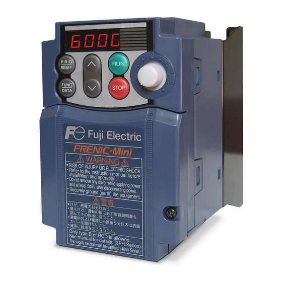
Page 31: External View And Terminal Blocks
(*When connecting the RS-485 communications cable, remove the control circuit terminal block cover and snip off the barrier provided in it using nippers.) Note: A box ( ) in model names replaces A, C, E, or U depending on shipping destination. Figure 2.1 External View of FRENIC-Mini RJ-45 connecotr SINK/SOURCE jumper switch…
-
Page 32: Names And Functions Of Keypad Components
POT. Pressing this key in Alarm mode displays information concerning the alarm code currently displayed on the LED monitor. * FRENIC-Mini features three operation modes—Running, Programming, and Alarm modes. Refer to Chapter 3, Section 3.1 «Overview of Operation Modes.»…
-
Page 33
2.2 Names and Functions of Keypad Components LED monitor In Running mode, the LED monitor displays running status information (output frequency, current or voltage); in Programming mode, it displays menus, function codes and their data; in Alarm mode, it displays an alarm code which identifies the error factor if the protective function is activated. If one of LED4 through LED1 is blinking, it means that the cursor is at this digit, allowing you to change it. -
Page 34
In Running mode, the cursor moves along digits; in Programming mode, it moves not only along digits but to the next function code. Simultaneous keying Simultaneous keying means depressing two keys at the same time (expressed by «+»). FRENIC-Mini supports simultaneous keying as listed below. (For example, the expression «… -
Page 35: Operation Using The Keypad
Chapter 3 OPERATION USING THE KEYPAD This chapter describes inverter operation using the keypad. The inverter features three operation modes (Running, Programming and Alarm modes) which enable you to run and stop the motor, monitor running status, set function code data, display running information required for maintenance, and display alarm data. Contents 3.1 Overview of Operation Modes……………………
-
Page 37: Overview Of Operation Modes
3.1 Overview of Operation Modes 3.1 Overview of Operation Modes FRENIC-Mini features the following three operation modes: Running mode : This mode allows you to enter run/stop commands in regular operation. You may also monitor the running status in realtime.
-
Page 38
The figure below shows the transition between the running status monitoring screens in Running mode, that between the menu screens in Programming mode, and that between the alarm code screens in Alarm mode. *1 The speed monitor may display the output frequency (Hz), reference frequency (Hz), load shaft speed (r/min), line speed (m/min.), and constant feeding rate time (min.) which can be selected by setting up function code E48. -
Page 39: Running Mode
3.2 Running Mode 3.2 Running Mode If the inverter is turned ON, it automatically enters Running mode in which you may: Run/stop the motor Set up the reference frequency and PID process command Monitor the running status (e.g., output frequency, output current) (4) Jog (inch) the motor 3.2.1 Run/stop the motor By factory default, pressing the…
-
Page 40
E48 data «LED monitor details Display of reference frequency Conversion of displayed value (Select speed monitor)» 0: Output frequency (before slip Frequency setting compensation) 1: Output frequency (after slip Frequency setting compensation) 2: Reference frequency Frequency setting 4: Load shaft speed Load shaft speed setting Frequency setting x E50 5: Line speed… -
Page 41: Monitor The Running Status
3.2 Running Mode • When setting the frequency and others with keys, the lowest digit on the display will blink. Change the setting, starting from the lowest digit and the cursor will move gradually to the next digit to be changed. •…
-
Page 42
Figure 3.3 shows the procedure example for selecting the desired monitor item. *1 The speed monitor may display the output frequency (Hz), reference frequency (Hz), load shaft speed (r/min), line speed (m/min.), and contrast feeding rate time (min.) which can be selected by setting up function code E48. *2 These PID-related information will appear only when the inverter is under the PID control. -
Page 43: Jog (Inch) The Motor
3.2 Running Mode Table 3.2 lists the display items for the speed monitor that can be chosen with function code E48. Table 3.2 Display Items on the Speed Monitor Speed monitor items Function code E48 data Meaning of Displayed Value Output frequency (before Pre-slip compensation frequency slip compensation) (Hz)
-
Page 44: Programming Mode
3.3 Programming Mode Pressing the key in Running mode switches the inverter to Programming mode. This mode provides the following functions which can be easily selected with the menu-driven system. (1) Data setting (Menu #1) (2) Data checking (Menu #2) (3) Drive monitoring (Menu #3) (4) I/O checking…
-
Page 45: Setting The Function Codes—«Data Setting
Menu #1 «Data setting» in Programming mode allows you to set function codes for making the inverter functions match your needs. The table below lists the function codes available in the FRENIC-Mini. The function codes are displayed on the LED monitor on the keypad as shown below.
-
Page 46
Function codes that require simultaneous keying To change data for function codes F00 (Data Protection) and H03 (Data Initialization), simultaneous keying operation is necessary— keys or keys. This prevents data from being lost by mistake. Changing, validating, and saving of function code data during running Some function code data can be changed while the motor is running and some cannot. -
Page 47
3.3 Programming Mode Figure 3.4 shows the status transition for Menu #1 «Data setting» and Figure 3.5 shows an example of the function code data changing procedure. Figure 3.4 Status Transition Diagram for «Data Setting» 3-11… -
Page 48
Figure 3.5 Example of Function Code Data Changing Procedure Basic key operation This section will give a description of the basic key operation, following the example of the function code data changing procedure shown in Figure 3.5. This example shows you how to change function code F01 data from the factory default of «Potentiometer operation on the keypad (F01 = 4)»… -
Page 49: Checking Changed Function Codes—«Data Checking
3.3 Programming Mode 3.3.2 Checking changed function codes—«Data Checking» Menu #2 «Data checking» in Programming mode allows you to check function code data that have been changed. Only data that has been changed from the factory defaults are displayed on the LED monitor.
-
Page 50: Monitoring The Running Status—«Drive Monitoring
3.3.3 Monitoring the running status—«Drive Monitoring» Menu #3 «Drive monitoring» is used to check the running status during maintenance and test running. The display items for «Drive monitoring» are listed in Table 3.5. Using keys, you may check those items in succession. Figure 3.7 shows the status transition diagram for «Drive monitoring.» Table 3.5 Drive Monitoring Display Items LED monitor Contents…
-
Page 51
3.3 Programming Mode Figure 3.7 Drive Monitoring Status Transition Basic key operation #ope (1) With the menu displayed, use keys to select «Drive monitoring» ( 3_00 (2) Press the key to display the desired code in the monitoring items list (e.g. (3) Use keys to select the desired monitoring item, then press the key. -
Page 52
Displaying running status To display the running status in hexadecimal format, each state has been assigned to bit 0 to 15 as listed in Table 3.6. Table 3.7 shows the relationship between each of the status assignments and the LED monitor display. Table 3.8 gives the conversion table from 4-bit binary to hexadecimal. Table 3.6 Running Status Bit Allocation Notation Content… -
Page 53: Checking I/O Signal Status—«I/O Checking
3.3 Programming Mode Hexadecimal expression A 16-bit binary number is expressed in hexadecimal format (4 bits). Table 3.8 shows the expression corresponding to decimals. The hexadecimals are shown as they appear on the LED monitor. Table 3.8 Binary and Hexadecimal Conversion Binary Hexadecimal Decimal Binary…
-
Page 54
Figure 3.8 Status Transition of I/O Check Basic key operation $i_o (1) With the menu displayed, use keys to select «I/O check»( 4_00 (2) Press the key to display the codes for the I/O check item list. (e.g. (3) Use keys to select the desired I/O check item, then press the key. -
Page 55
3.3 Programming Mode [ 1 ] Displaying control I/O signal terminals The I/O signal status of control circuit terminals may be displayed with ON/OFF of the LED segment or in hexadecimal display. Display I/O signal status with ON/OFF of the LED segment As shown in Table 3.10 and the figure below, segments «a»… -
Page 56
«0.» Allocated bit data is displayed on the LED monitor in 4-digit hexadecimals («0» to «F» each). With the FRENIC-Mini, digital input terminals [FWD] and [REV] are assigned to bit 0 and bit 1, respectively. Terminals [X1] through [X3] are assigned to bits 2 through 4. The value «1» is set for each bit when the assigned input terminal is short-circuited (ON) with terminal [CM]. -
Page 57: Reading Maintenance Information—«Maintenance Information
5_05 Capacitance of the Shows the current capacitance of the DC link bus capacitor, based on DC link bus the capacitance when shipped as 100%. Refer to the FRENIC-Mini capacitor Instruction Manual, Chapter 7 «MAINTENANCE AND INSPECTION» for details. Unit: %…
-
Page 58
Table 3.12 Maintenance Display Items (Continued) LED monitor Display contents Description shows: 5_10 Input watt-hour Shows the value expressed by «input watt-hour (kWh) × E51 (whose data data range is 0.000 to 9,999).» Unit: None. (Display range: 0.001 to 9999. The data cannot exceed 9999. (It will be fixed at 9,999 once the calculated value exceeds 9999.)) Depending on the value of integrated input watt-hour data, the decimal point on the LED monitor shifts to show it within the LED… -
Page 59
3.3 Programming Mode Figure 3.9 Status Transition of Maintenance Information Basic key operations %che (1) With the menu displayed, use keys to select «Maintenance information» ( 5_00 (2) Press the key to display the list of maintenance item codes (e.g. (3) Use keys to select the desired maintenance item, then press the key. -
Page 60: Reading Alarm Information—«Alarm Information
3.3.6 Reading alarm information—«Alarm Information» Menu #6 «Alarm information» in Programming mode shows the cause of the past 4 alarms as alarm codes. Further, it is also possible to display alarm information that indicates the status of the inverter when the alarm occurred. Table 3.13 shows the contents of the alarm information and Figure 3.10 shows the status transition of the alarm information.
-
Page 61
3.3 Programming Mode Table 3.13 Alarm Information Contents (Continued) LED monitor Display contents Description shows: (Item No.) 6_17 Overlapping alarm 2 Simultaneously occurring alarm codes (2) (– – – – is displayed if no alarms have occurred.) 6_18 Terminal I/O signal status under communication control (displayed… -
Page 62
Table 3.15 Running Status 3 ( 6_24 ) Bit Assignment Notation Content Notation Content (Not used.) (Not used.) Current detected 2 (Not used.) Low current detected Motor overload early warning Auto-restarting after momentary Current detected power failure Overload prevention control SWM2 Motor 2 selected LIFE… -
Page 63
3.3 Programming Mode Figure 3.10 Status Transition of Alarm Information Basic key operations &al (1) With the menu displayed, use keys to select «Alarm information» ( !0l1 (2) Press the key to display the alarm list code (e.g. In the list of alarm codes, the alarm information for the last 4 alarms will be saved as an alarm history. -
Page 64: Alarm Mode
3.4 Alarm Mode When the protective function is activated to issue an alarm, the inverter automatically transfers to Alarm mode and the alarm code will appear in the LED monitor. Figure 3.11 shows the status transition of Alarm mode. Figure 3.11 Status Transition of Alarm Mode 3.4.1 Releasing the alarm and transferring the inverter to Running mode Remove the cause of the alarm and press the…
-
Page 65: Displaying The Running Information When An Alarm Occurs
3.4 Alarm Mode 3.4.3 Displaying the running information when an alarm occurs If an alarm occurs, you may check various running status information (output frequency and output current, etc.) by pressing the key when the alarm code is displayed. The item number and data for each running information is displayed in alternation.
-
Page 67
Chapter 4 BLOCK DIAGRAMS FOR CONTROL LOGIC This chapter describes the main block diagrams for the control logic of the FRENIC-Mini series of inverters. Contents 4.1 Symbols Used in the Block Diagrams and their Meanings…………….. 4-1 4.2 Drive Frequency Command Generator ………………….. 4-2 4.3 Drive Command Generator ……………………. -
Page 69: Symbols Used In The Block Diagrams And Their Meanings
4.1 Symbols Used in the Block Diagrams and their Meanings FRENIC-Mini inverters are equipped with a number of function codes to match a variety of motor operations required in your system. Refer to Chapter 9 «FUNCTION CODES» for details of the function codes.
-
Page 70: Drive Frequency Command Generator
4.2 Drive Frequency Command Generator Figure 4.1 Block Diagram for Drive Frequency Command Generator…
-
Page 71
4.2 Drive Frequency Command Generator Figure 4.1 shows the processes that generate the final drive frequency command from the frequency settings given by various means and those switched/modified by function codes. If PID process control takes effect (J01=1 or 2), the drive frequency generation will differ from that shown in this diagram. (Refer to Section 4.8 «PID Frequency Command Generator.») Additional and supplemental information is given below. -
Page 72: Drive Command Generator
4.3 Drive Command Generator Figure 4.2 Drive Command Generator…
-
Page 73
4.3 Drive Command Generator The drive command generator shown in Figure 4.2 produces final drive commands (FWD: Drive the motor in the forward direction) and (REV: Drive the motor in reverse direction) from the run commands that are given by various means and modified/switched by function codes. Additional and supplemental information is given below. -
Page 74: Terminal Command Decoders
4.4 Terminal Command Decoders Figures 4.3 (a) through (d) show five types of the terminal command decoder for the digital input signals. Enable [X1] Communications Link Normal/Negative Logic Selection (LE) [X1] [X1] <1000 SS1 (X1) ≧1000 SS2 (X1) Communications Link Function Link for Supporting SS4 (X1)
-
Page 75
4.4 Terminal Command Decoders [X1] [X1] Normal/Negative Logic Selection [X1] <1000 Enable External Alarm Trip (THR) ≧1000 [X2] [X2] Normal/Negative Logic Selection Enable [X2] Communications <1000 Link (LE) ≧1000 [X3] [X3] Normal/Negative Logic Selection [X3] <1000 Note) Each number shown at switches E01 to ≧1000 E03, E98 and E99 is data in normal logic system. -
Page 76
Figure 4.3 (d) Terminal Command Decoder (ORing with Link Commands/Ignoring Link Commands) -
Page 77
4.4 Terminal Command Decoders Programmable digital input terminals [X1], [X2], [X3], [FWD] and [REV] can be assigned to internal terminal commands such as FWD or REV decoded by data settings of related function codes as shown in the block diagrams in Figures 4.3 (a) through 4.3 (d). In the decoders, negative logic input signals are also applicable if you set data of 1000s to the function code. -
Page 78: Digital Output Selector
4.5 Digital Output Selector [Y1] (Transistor output) Frequency (RUN) Inverter running (Speed > 0) Transistor Output Detection <1000 (FAR) [Y1] Frequency arrival signal (Hysteresis width) Output frequency 1 (before 1.0 Hz (FDT) Frequency detected slip compensation) ≧1000 Frequency Detection (LU) Undervoltage detected (Detection level) (IOL)
-
Page 79
4.5 Digital Output Selector The block diagram shown in Figure 4.4 shows you the processes to select the internal logic signals for feeding to two digital output signals [Y1] and [30A/B/C]. The output terminals [Y1] (a transistor switch) and [30A/B/C] (mechanical relay contacts) are programmable. You can assign various functions to these terminals using function codes E20 and E27. -
Page 80: Analog Output (Fma) Selector
4.6 Analog Output (FMA) Selector [FMA] (Output Gain) [FMA] (Selector) Analog Output Output Frequency 1 × [FMA] (Before Slip Compensation) Output Frequency 2 × (After Slip Compensation) × Output Current × Output Voltage × Input Power × PID Feedback Value ×…
-
Page 81: Drive Command Controller
4.7 Drive Command Controller 4.7 Drive Command Controller Figures 4.6 (a) and (b) show the drive command controller. Maximum frequency 1 Base frequency 1 Rotational Starting frequency 1 direction (Holding time) limitation Stop frequency (Holding time) «0» ACC/DEC processor × «-1″…
-
Page 82
Power Rectifier DC link bus source capacitor Cooling fan Motor Cooling fan Output current ON-OFF Gate drive circuit (Iu, Iv, Iw) control Cooling fan PWM signals ON-OFF control Instantaneous overcurrent limiting (Mode selection) Output Current Alarm (Iu, Iv, Iw) Current limit level Current limit processing Maximum frequency 1… -
Page 83
4.7 Drive Command Controller The simplified block diagram shown in Figure 4.6 explains the process in which the inverter drives the motor according to the internal run command <FWD>/<REV> from the frequency generator, or the PID frequency command from the PID controller, and the run commands. Additional and supplemental information is given below. -
Page 84: Pid Frequency Command Generator
4.8 PID Frequency Command Generator Figure 4.7 PID Frequency Command Generator 4-16…
-
Page 85
4.8 PID Frequency Command Generator The block diagram shown in Figure 4.7 shows the PID frequency command generator that becomes active when the PID control is enabled (J01= 1 or 2). The logic shown generates the final frequency command according to the PID process command given by various means of setting and feedback, or frequency settings as a speed command given manually, and various means of switching. -
Page 87
Chapter 5 RUNNING THROUGH RS-485 COMMUNICATIONS This chapter describes an overview of inverter operation through the RS-485 communications link. Refer to the RS-485 Communication User’s Manual (MEH448) for details. Contents 5.1 Overview on RS-485 Communication ………………….5-1 5.1.1 Common specifications……………………5-2 5.1.2 Connector specifications …………………… -
Page 89: Overview On Rs-485 Communication
Operation from the host equipment The FRENIC-Mini can be connected to host equipment (master) such as a PLC or computer. It can act as a slave device. Protocols for managing a network including inverters include the Modbus RTU protocol (compliant to the protocol established by Modicon Inc.) that is widely used in FA markets and the Fuji…
-
Page 90: Common Specifications
5.1.1 Common specifications Items Specifications Protocol FGI-BUS Modbus RTU Loader protocol Compliance Fuji general-purpose Modicon Modbus Special commands RS-485 communication RTU-compliant dedicated to Loader (Not disclosed) No. of supporting Host device: 1 stations Inverters: Up to 31 Max. transmission 500 m (1600 ft.) cable length No.
-
Page 91: Connector Specifications
The RJ-45 connector has power source pins (pins 1 and
 designed for the remote keypad. When connecting other devices to the RJ-45 connector, take care not to use those pins. For the details about the terminating resistor switch, refer to the FRENIC-Mini Instruction Manual, Section 2.3.7 «Setting up the slide switches.»…
 -
Page 92: Connection
For the connection of the remote keypad, use an 8-wire straight cable with an RJ-45 connector. (Remote keypad extension cable option: CB-5S) For the connection of other equipment or connection of FRENIC-Mini inverters with each other, use a cable that has signal wires only. (EIA568-compliant 10BASE-T) — No converter is required for connection of the remote keypad.
-
Page 93: Overview Of Frenic Loader
5.2 Overview of FRENIC Loader 5.2 Overview of FRENIC Loader FRENIC Loader is a software tool that supports the operation of the inverter via an RS-485 communications link. It allows you to remotely run or stop the inverter, edit, set, or manage the function codes, monitor key parameters and values during operation, as well as monitoring the running status (including alarm information) of the inverters on the RS-485 communications network.
-
Page 94: Connection
5.2.2 Connection By connecting a number of inverters to one PC, you can control one inverter at a time or a number of inverters simultaneously. You can also simultaneously monitor a number of inverters on the multi-monitor. For instructions on how to connect inverters to a PC, refer to Section 5.1.3 «Connection» in this manual and the RS-485 Communication User’s Manual (MEH448).
-
Page 95: Running Status Monitor
5.2 Overview of FRENIC Loader Comparison You can compare the function code data currently being edited with that saved in a file or stored in the inverter. To perform a comparison and review the result displayed, click the Comparison tab and then click the Compared with inverter tab or click the Compared with file tab, and specify the file name.
-
Page 96
System monitor Allows you to check the inverter’s system information (version, model, maintenance information, etc.). Alarm monitor The alarm monitor shows the alarm status of the selected inverter. In this window, you can check the details of the alarm that currently occurs and the related information. -
Page 97: Test-Running
5.2 Overview of FRENIC Loader 5.2.3.3 Test-running The test-running feature allows you to test-run the motor in the forward or reverse direction while monitoring the running status of the selected inverter. LED monitor Shows the running status (output frequency, current, etc.). Reference frequency Operationsta…
-
Page 99
Chapter 6 SELECTING PERIPHERAL EQUIPMENT This chapter describes how to use a range of peripheral equipment and options, FRENIC-Mini’s configuration with them, and requirements and precautions for selecting wires and crimp terminals. Contents 6.1 Configuring the FRENIC-Mini ……………………6-1 6.2 Selecting Wires and Crimp Terminals………………….6-2 6.2.1… -
Page 101: Configuring The Frenic-Mini
6.1 Configuring the FRENIC-Mini 6.1 Configuring the FRENIC-Mini This section lists the names and features of peripheral equipment and options for the FRENIC-Mini series of inverters and includes a configuration example for reference. Refer to Figure 6.1 for a quick overview of available options.
-
Page 102: Selecting Wires And Crimp Terminals
To solve such noise-related problems, refer to Appendix A «Advantageous Use of Inverters (Notes on electrical noise)» in this manual and the Inverter Panel Design Technical Document. At the time of actual construction, refer to the FRENIC-Mini Instruction Manual, Chapter 2 «Mounting and Wiring of the Inverter,» Wiring precautions.
-
Page 103
6.2 Selecting Wires and Crimp Terminals Currents Flowing across the Inverter Terminals Table 6.1 summarizes average (effective) electric currents flowing across the terminals of each inverter model for ease of reference when selecting peripheral equipment, options and electric wires for each inverter—including supplied power voltage and applicable motor rating. Table 6.1 Currents Flowing through Inverter 50Hz, 200V / 400V (380V) 60Hz, 220V (200V) / 440V (380V) -
Page 104: Recommended Wires
6.2.1 Recommended wires Tables 6.2 and 6.3 list the recommended wires according to the internal temperature of your power control cabinet. If the internal temperature of your power control cabinet is 50°C (122°F) or below Table 6.2 Wire Size (kW, mm ratings) (for main circuit power input and inverter output) Recommended wire size (mm ) at 50°C (122°F) or below…
-
Page 105
6.2 Selecting Wires and Crimp Terminals Table 6.2 Cont. (kW, mm ratings) (for DC reactor, braking resistor, control circuits, and inverter grounding) Recommended wire size (mm ) at 50°C (122°F) or below DC reactor Braking resistor Inverter Applicable Power Control circuit [P1, P(+)] [P(+), DB] grounding z[G]… -
Page 106
Table 6.2 Cont. Wire Size (HP, AWG ratings) (for main circuit power input and inverter output) Recommended wire size (AWG) at 50°C (122°F) or below Main circuit power input Applicable Power [L1/R , L2/S , L3/T] or [L1/L, L2/N] Inverter output [U , V , W] motor supply Inverter type… -
Page 107
6.2 Selecting Wires and Crimp Terminals Table 6.2 Cont. (HP, AWG ratings) (for DC reactor, braking resistor, control circuits, and inverter grounding) Recommended wire size (AWG) at 50°C (122°F) or below DC reactor Braking resistor Inverter Applicable Power Control circuit [P1, P(+)] [P(+), DB] grounding z[G]… -
Page 108
If the internal temperature of your power control cabinet is 40°C (104°F) or below Table 6.3 Wire Size (kW, mm ratings) (for main circuit power input and inverter output) Recommended wire size (mm ) at 40°C (104°F) or below Main circuit power input Applicable Power [L1/R , L2/S , L3/T] or [L1/L, L2/N]… -
Page 109
6.2 Selecting Wires and Crimp Terminals Table 6.3 Cont. (kW, mm ratings) (for DC reactor, braking resistor, control circuit, and inverter grounding) Recommended wire size (mm ) at 40°C (104°F) or below Applicable Braking resistor Inverter Control circuit Power DC reactor [P(+), DB] grounding z[G] motor… -
Page 110
Table 6.3 Cont. Wire Size (HP, AWG ratings) (for main circuit power input and inverter output) Recommended wire size (AWG) at 40°C (104°F) or below Main circuit power input Applicable Power [L1/R , L2/S , L3/T] or [L1/L, L2/N] Inverter output [U , V , W] motor supply Inverter type… -
Page 111
6.2 Selecting Wires and Crimp Terminals Table 6.3 Cont. (HP, AWG ratings) (for DC reactor, braking resistor, control circuit, and inverter grounding) Recommended wire size (AWG) at 40°C (104°F) or below Applicable Braking resistor Inverter Control circuit Power DC reactor [P(+), DB] grounding z[G] motor… -
Page 112: Crimp Terminals
6.2.2 Crimp terminals Table 6.4 lists the recommended ring tongue crimp terminals that can be specified by the wires and screws to be used for your inverter model. Table 6.4 Crimp Terminal Size Wire size (mm Terminal screw size Ring tongue crimp terminal M3.5 1.25 — 3.5 1.25 — 4…
-
Page 113: Peripheral Equipment
6.3 Peripheral Equipment 6.3 Peripheral Equipment [ 1 ] Molded case circuit breaker (MCCB), earth leakage circuit breaker (ELCB) and magnetic contactor (MC) [ 1.1 ] Functional overview MCCBs and ELCBs* *With overcurrent protection Molded Case Circuit Breakers (MCCBs) are designed to protect the power circuits between the power supply and inverter’s main circuit terminals (L1/R, L2/S and L3/T for three phase, or L1/L and L2/N for single-phase power source) from overload or short-circuit, which in turn prevents secondary accidents caused by the inverter malfunctioning.
-
Page 114
Driving the motor using commercial power lines MCs can also be used to switch the power source of the motor driven by the inverter to a commercial power source. Select the MC so as to satisfy the rated currents listed in Table 6.1, which are the most critical RMS currents for using the inverter. -
Page 115: Magnetic Contactor (Mc)
6.3 Peripheral Equipment Table 6.5 Rated Current of Molded Case Circuit Breaker/Earth Leakage Circuit Breaker and Magnetic Contactor MCCB, ELCB Magnetic contactor type Applicable Applicable Magnetic Rated current (A) MC1 (for input circuit) Power motor motor contactor type supply Inverter type rating rating DC reactor (DCR)
-
Page 116
Table 6.6 lists the relationship between the rated leakage current sensitivity of ELCBs (with overcurrent protection) and wiring length of the inverter output circuits. Note that the sensitivity levels listed in the table are estimated values based on the results obtained by the test setup in the Fuji laboratory where each inverter drives a single motor. -
Page 117: 2 ] Surge Killers
The applicable model of surge killer is the FSL-323. Figure 6.3 shows its external dimensions and a connection example. Refer to the catalog «Fuji Noise Suppressors (SH310: Japanese edition only)» for details. These products are available from Fuji Electric Technica Co., Ltd. Figure 6.3 Dimensions of Surge Killer and Connection Example…
-
Page 118: 3 ] Arresters
250 VAC, 10 kA or less. Arrester Plug fuse or separator *2 MCCB (N-phase terminal is only for CN5234 and CN5234-K.) Available from Fuji Electric Technica Co., Ltd. Figure 6.4 Arrester Dimensions and Connection Examples 6-18…
-
Page 119: 4 ] Surge Absorbers
Applicable surge absorber models are the S2-A-O and S1-B-O. Figure 6.5 shows their external dimensions. Refer to the catalog «Fuji Noise Suppressors (SH310: Japanese edition only)» for details. The surge absorbers are available from Fuji Electric Technica Co., Ltd. Figure 6.5 Surge Absorber Dimensions…
-
Page 120: Selecting Options
(as an overheating warning signal). To ensure that the signal is recognized at one of the digital input terminals of the FRENIC-Mini, assign the external alarm (THR) to any of terminals [X1] to [X3], [FWD] and [REV]. Connect the assigned terminal to terminal [1] of the braking resistor. Upon detection of the warning signal (preset detection level: 150°C (302°F)), the inverter simultaneously…
-
Page 121
6.4 Selecting Options Table 6.7 Braking Resistor (Standard Model) Continuous braking Repetitive braking Option Max. braking torque (%) (100% torque (100 sec or less cycle) Power conversion value) supply Inverter type Braking resistor 50 Hz 60 Hz Discharging Braking Average voltage Duty cycle capability… -
Page 122
[ 1.2 ] 10%ED model Figure 6.7 Braking Resistor (10 %ED Model) and Connection Example Table 6.8 Braking Resistor (10 %ED Model) Continuous braking Repetitive braking Option Max. braking torque (%) (100% torque (100 sec or less cycle) Power conversion value) supply Inverter type Braking resistor… -
Page 123
6.4 Selecting Options [ 1.3 ] Compact model Figure 6.8 Braking Resistor (Compact Model) and Connection Example Table 6.9 Braking Resistor (Compact Model) Power supply Item Model: TK80W120Ω voltage Capacity (kW) 0.08 Resistor Resistance (Ω) FRN0004 FRN0006 FRN0010 FRN0012 FRN0020 Applicable inverter model ■… -
Page 124: 2 ] Dc Reactors (Dcrs)
[ 2 ] DC reactors (DCRs) A DCR is mainly used for power supply normalization and for supplied power factor improvement (for reducing harmonic components). For power supply normalization — Use a DCR when the capacity of a power supply transformer exceeds 500 kVA and is 10 times or more the rated inverter capacity.
-
Page 125
6.4 Selecting Options Table 6.10 DC Reactors (DCRs) Power Applicable Applicable DC reactor (DCR) supply motor motor Inverter type Rated current Inductance Coil resistance Generated loss voltage rating rating Type (mH) (mΩ ) (kW) (HP) FRN0001C2S-2 DCR2-0.2 FRN0002C2S-2 FRN0004C2S-2 DCR2-0.4 0.75 FRN0006C2S-2 DCR2-0.75… -
Page 126: 3 ] Ac Reactors (Acrs)
[ 3 ] AC reactors (ACRs) Use an ACR when the converter part of the inverter should supply very stable DC power, for example, in DC link bus operation (shared PN operation). Generally, ACRs are used for correction of voltage waveform and power factor or for power supply normalization, but not for suppressing harmonic components in the power lines.
-
Page 127
6.4 Selecting Options Table 6.11 AC Reactor (ACR) AC reactor (ACR) Applicable Applicable Power motor motor supply Inverter type Reactance (mΩ/phase) Rated current Generated loss rating rating Type voltage (kW) (HP) 50 Hz 60 Hz FRN0001C2S-2 ACR2-0.4A 1100 FRN0002C2S-2 FRN0004C2S-2 FRN0006C2S-2 0.75 ACR2-0.75A… -
Page 128: 4 ] Output Circuit Filters (Ofls)
[ 4 ] Output circuit filters (OFLs) Insert an OFL in the inverter power output circuit to: — Suppress the voltage fluctuation at the motor power terminals This protects the motor from insulation damage caused by the application of high voltage surge currents from the 400 V class of inverters.
-
Page 129
6.4 Selecting Options Table 6.12 Output Circuit Filter (OFL) Allowable Applicable Applicable Inverter Power Rated carrier Maximum motor motor Overload power supply Inverter type Filter model current frequency — frequency rating rating capability input voltage range (Hz) (kW) (HP) voltage (kHz) FRN0001C2S-2 OFL-0.4-2… -
Page 130: 5 ] Surge Suppression Unit (Ssu)
[ 5 ] Surge suppression unit (SSU) If the drive wire for the motor is long, an extremely low surge voltage (micro surge) occurs at the wire end connected to the motor. Surge voltage causes motor degradation, insulation breakdown, or increased noises. The surge suppression unit (SSU) suppresses the surge voltage.
-
Page 131: 6 ] Zero-Phase Reactors For Reducing Radio Noise (Acls)
6.4 Selecting Options [ 6 ] Zero-phase reactors for reducing radio noise (ACLs) An ACL is used to reduce radio frequency noise emitted from the inverter output lines. Pass the total of four wires—three inverter output wires and a grounding wire through the ACL in the same passing direction four times.
-
Page 132: 7 ] Options For 100 V Single-Phase Power Supply
[ 7 ] Options for 100 V single-phase power supply An optional 100 V single-phase power supply may be used to operate an inverter designed for a 200 V 3-phase power supply with 100 V single-phase power. Select an option with correct capacity according to the specifications listed in Table 6.14.
-
Page 133: Options For Operation And Communications
6.4 Selecting Options 6.4.2 Options for operation and communications [ 1 ] External potentiometer for frequency setting An external potentiometer may be used to set the drive frequency. Connect the potentiometer to control signal terminals [11] to [13] of the inverter as shown in Figure 6.14. Model: RJ-13 (BA-2 B-characteristics, 1 kΩ) Model: WAR3W (3W B-characteristics, 1 kΩ) Figure 6.14 External Potentiometer Dimensions and Connection Example…
-
Page 134: 2 ] Remote Keypad «Tp-E1
[ 2 ] Remote keypad «TP-E1» The keypad permits remote control of FRENIC-Mini, and function setting and display (with copy function). 6-34…
-
Page 135: 3 ] Usb-Equipped Remote Keypad (Tp-E1U)
6.4 Selecting Options [ 3 ] USB-equipped remote keypad (TP-E1U) Using the keypad in combination with FRENIC Loader enables a variety of data about the inverter unit to be saved in the keypad memory, allowing you to check the information in any place. <Example of use in the office>…
-
Page 136: 4 ] Extension Cable For Remote Operation (Cb- S)
[ 4 ] Extension cable for remote operation (CB- S) The extension cable connects the inverter with the remote keypad to enable remote operation of the inverter. The cable is a straight-wired type with RJ-45 jacks and its length is selectable from 5 m (16.4 ft), 3 m (9.8 ft), and 1 m (3.3 ft).
-
Page 137: Extended Installation Kit Options
6.4.3 Extended installation kit options [ 1 ] Mounting adapters FRENIC-Mini series of inverters can be installed in the control board of your system using mounting adapters which utilize the mounting holes used for conventional inverters (FVR-E11S series of 0.75 kW or below or 3.7 (4.0) kW).
-
Page 138: 2 ] Rail Mounting Bases
[ 2 ] Rail mounting bases A rail mounting base allows any of the FRENIC-Mini series of inverter to be mounted on a DIN rail (35 mm (1.38 inches) wide). Table 6.16 Rail Mounting Base Option model Applicable inverter type FRN0001C2S-2 RMA-C1-0.75…
-
Page 139: 3 ] Nema1 Kit
6.4 Selecting Options [ 3 ] NEMA1 kit (NEMA1- C2- ) Mounting the NEMA1 kit on the FRENIC-Mini series of inverters brings the inverter’s enclosure into compliance with the NEMA1 Standard (UL TYPE1 certified). Table 6.17 NEMA1 Kit Power Inverter type…
-
Page 140: Meter Options
6.4.4 Meter options [ 1 ] Frequency meters Connect a frequency meter to analog signal output terminals [FMA] (+) and [11] (-) of the inverter to measure the frequency component selected by function code F31. Figure 6.15 shows the dimensions of the frequency meter and a connection example.
-
Page 141
Chapter 7 SELECTING OPTIMAL MOTOR AND INVERTER CAPACITIES This chapter provides you with information about the inverter output torque characteristics, selection procedure, and equations for calculating capacities to help you select optimal motor and inverter models. It also helps you select braking resistors. Contents 7.1 Selecting Motors and Inverters …………………… -
Page 143: Selecting Motors And Inverters
(1) above, calculate the acceleration/deceleration/braking torque. This section describes the selection procedure for (1) and (2) above. First, it explains the output torque obtained by using the motor driven by the inverter (FRENIC-Mini). 7.1.1 Motor output torque characteristics Figures 7.1 and 7.2 graph the output torque characteristics of motors at the rated output frequency…
-
Page 144
Figure 7.2 Output Torque Characteristics (Base frequency: 60 Hz) Continuous allowable driving torque (Curve (a) in Figures 7.1 and 7.2) Curve (a) shows the torque characteristic that can be obtained in the range of the inverter continuous rated current, where the motor cooling characteristic is taken into consideration. When the motor runs at the base frequency of 60 Hz, 100 % output torque can be obtained;… -
Page 145
7.1 Selecting Motors and Inverters Braking torque (Curves (d), (e), and (f) in Figures 7.1 and 7.2) In braking the motor, kinetic energy is converted to electrical energy and regenerated to the DC link bus capacitor (reservoir capacitor) of the inverter. Discharging this electrical energy to the braking resistor produces a large braking torque as shown in curve (e). -
Page 146: Selection Procedure
7.1.2 Selection procedure Figure 7.3 shows the general selection procedure for optimal inverters. Items numbered (1) through (5) are described on the following pages. You may easily select inverter capacity if there are no restrictions on acceleration and deceleration times. If «there are any restrictions on acceleration or deceleration time» or «acceleration and deceleration are frequent,»…
-
Page 147
7.1 Selecting Motors and Inverters Calculating the load torque during constant speed running (For detailed calculation, refer to Section 7.1.3.1) It is essential to calculate the load torque during constant speed running for all loads. First calculate the load torque of the motor during constant speed running and then select a tentative capacity so that the continuous rated torque of the motor during constant speed running becomes higher than the load torque. -
Page 148
Deceleration time (For detailed calculation, refer to Section 7.1.3.2) To calculate the deceleration time, check the motor deceleration torque characteristics for the whole range of speed in the same way as for the acceleration time. 1) Calculate the moment of inertia for the load and motor Same as for the acceleration time. -
Page 149: Equations For Selections
7.1 Selecting Motors and Inverters 7.1.3 Equations for selections 7.1.3.1 Load torque during constant speed running [ 1 ] General equation The frictional force acting on a horizontally moved load must be calculated. Calculation for driving a load along a straight line with the motor is shown below. Where the force to move a load linearly at constant speed υ…
-
Page 150: Acceleration And Deceleration Time Calculation
7.1.3.2 Acceleration and deceleration time calculation When an object whose moment of inertia is J (kg·m ) rotates at the speed N (r/min), it has the following kinetic energy: π • (7.5) • To accelerate the above rotational object, the kinetic energy will be increased; to decelerate the object, the kinetic energy must be discharged.
-
Page 151
7.1 Selecting Motors and Inverters Table 7.1 Moment of Inertia of Various Rotating Bodies Mass: W (kg) Mass: W (kg) Shape Shape Moment of inertia: Moment of inertia: J (kg·m J (kg·m π Hollow cylinder − ρ ρ • • •… -
Page 152: 2 ] Calculation Of The Acceleration Time
For a load running horizontally Assume a carrier table driven by a motor as shown in Figure 7.7. If the table speed is υ (m/s) when the motor speed is N (r/min), then an equivalent distance from the rotation axis is equal to 60·υ / (2π·N m.
-
Page 153: Heat Energy Calculation Of Braking Resistor
7.1 Selecting Motors and Inverters 7.1.3.3 Heat energy calculation of braking resistor If the inverter brakes the motor, the kinetic energy of mechanical load is converted to electric energy to be regenerated into the inverter circuit. This regenerative energy is often consumed in so-called braking resistors as heat.
-
Page 154: Calculating The Rms Rating Of The Motor
7.1.3.4 Calculating the RMS rating of the motor In case of the load which is repeatedly and very frequently driven by a motor, the load current fluctuates largely and enters the short-time rating range of the motor repeatedly. Therefore, you have to review the thermal allowable rating of the motor.
-
Page 155: Selecting A Braking Resistor
7.2 Selecting a Braking Resistor 7.2 Selecting a Braking Resistor 7.2.1 Selection procedure The following three requirements must be satisfied simultaneously: 1) The maximum braking torque should not exceed values listed in Tables 6.7 to 6.9 in Chapter 6, Section 6.4.1 [1] «Braking resistors.» To use the maximum braking torque exceeding values in those tables, select the braking resistor having one class larger capacity.
-
Page 157
This chapter describes specifications of the output ratings, control system, and terminal functions for the FRENIC-Mini series of inverters. It also provides descriptions of the operating and storage environment, external dimensions, examples of basic connection diagrams, and details of the protective functions. -
Page 159: Chapter 8 Specifications
8.1 Standard Models 8.1 Standard Models 8.1.1 Three-phase 200 V series FRN_ _ _ _C2S-2 , where = A or U Item Specifications Type (FRN_ _ _ _C2S-2 ) 0001 0002 0004 0006 0010 0012 0020 0025 0033 0047 0060 Nominal applied motor (kW) * 0.75 = A)
-
Page 160: Three-Phase 400 V Series
8.1.2 Three-phase 400 V series FRN_ _ _ _C2S-4 , where = A, C, E, or U Item Specifications Type (FRN_ _ _ _C2S-4 ) 0002 0004 0005 0007 0011 0013 0018 0024 0030 Nominal applied motor (kW) * ( =A,C) 0.75 = A ,C or E) ( =E)
-
Page 161: Single-Phase 200 V Series
8.1 Standard Models 8.1.3 Single-phase 200 V series FRN_ _ _ _C2S-7 , where = A, C, E, or U Item Specifications Type (FRN_ _ _ _C2S-7 ) 0001 0002 0004 0006 0010 0012 Nominal applied motor (kW) * 0.75 = A ,C or E) Nominal applied motor (HP) * = U)
-
Page 162: Single-Phase 100 V Series
8.1.4 Single-phase 100 V series FRN_ _ _ _C2S-6 , where Item Specifications Type (FRN_ _ _ _C2S-6U) 0001 0002 0003 0005 Nominal applied motor (HP) * Rated capacity (kVA) * 0.26 0.53 0.95 Rated voltage (V) * Three-phase, 200 to 240 V (with AVR function) Rated current (A) Overload capability 150% of rated output current for 1 min or 200% of rated current for 0.5 s…
-
Page 163: Semi-Standard Models
8.2 Semi-standard Models 8.2 Semi-standard Models 8.2.1 EMC filter built-in type in three-phase 400 V series FRN_ _ _ _C2E-4 , where = C, E Item Specifications Type (FRN_ _ _ _C2E-4 ) 0002 0004 0005 0007 0011 0013 0018 0024 0030 = C or E)
-
Page 164: Emc Filter Built-In Type In Single-Phase 200 V Series
8.2.2 EMC filter built-in type in single-phase 200 V series FRN_ _ _ _C2E-7 , where = C, E Item Specifications Type (FRN_ _ _ _C2E-7 ) 0001 0002 0004 0006 0010 0012 = C, E) Nominal applied motor (kW) * 0.75 Nominal applied motor (HP) * Rated capacity (kVA) *…
-
Page 165: Common Specifications
8.3 Common Specifications 8.3 Common Specifications Item Explanation Maximum frequency 25.0 to 400.0 Hz variable Base frequency 25.0 to 400.0 Hz variable Starting frequency 0.1 to 60.0 Hz variable Carrier frequency 0.75 to 16 kHz variable Note: To protect the inverter, when the carrier frequency is 6 kHz or more, the carrier frequency automatically lowers depending upon the ambient temperature or output current states.
-
Page 166
Item Explanation Frequency setting Keypad operation using the keys (with data protection function). Also can be set with function code (only via communication) and be copied. Built-in potentiometer Analog input: 0 to ±10 V DC / 0 to 100% (terminal [12]), 4 to 20 mA / 0 to 100%, 0 to 20 mA / 0 to 100% (terminal [C1]) Multistep frequency: Selectable from 16 different frequencies (step 0 to 15) -
Page 167
8.3 Common Specifications Item Explanation Restart after momentary • Trip at power failure: The inverter trips immediately after power failure. power failure *1 • Trip at power recovery: Coast-to-stop at power failure and trip at power recovery • Deceleration stop: Deceleration stop at power failure, and trip after stoppage. -
Page 168
Item Explanation During running/stop Speed monitor, output current (A), output voltage (V), input power (kW), PID command value, PID feedback value, PID output, timer (s) and input watt-hour (kWh). Select the speed monitor to be displayed from the following: Output frequency (before slip compensation) (Hz), output frequency (after slip compensation) (Hz), reference frequency (Hz), load shaft speed (min ), line speed (m/min), constant feeding rate time (min). -
Page 169: Terminal Specifications
8.4 Terminal Specifications 8.4 Terminal Specifications 8.4.1 Terminal functions Main circuit and analog input terminals Related Symbol Name Functions function codes L1/R, L2/S, Main circuit Connects a three-phase power supply. L3/T power input (three-phase 200 V, 400 V series) L1/L, Connects a single-phase power supply.
-
Page 170
Related Symbol Name Functions function codes [C1] (For PTC Connects a PTC thermistor for motor protection. H26, thermistor) (Connect a 1 kΩ external resistor to terminal [13] — [C1].) (Frequency Used as additional auxiliary setting to various auxiliary setting) frequency settings. Electric characteristics of terminal [C1] Input impedance: 250Ω… -
Page 171
8.4 Terminal Specifications Related Symbol Name Functions function codes Since weak analog signals are handled, these signals are especially susceptible to the • external noise effects. Route the wiring as short as possible (within 20 m) and use shielded wires. In principle, ground the shielding layer of the shielded wires; if effects of external inductive noises are considerable, connection to terminal [11] may be effective. -
Page 172
Digital input terminals Related Symbol Name Functions function codes [X1] Digital input 1 Possible to assign various signals to terminals [X1] to E01 to [X3], [FWD] and [REV] using function codes. For [X2] Digital input 2 details, refer to Section 9.2.2 «E codes.» By factory default, FWD and REV signals are [X3] Digital input 3… -
Page 173
(a) With a jumper applied to SINK (b) With a jumper applied to SOURCE Figure 8.4 Circuit Configuration Using a PLC For details about the jumper setting, refer to the FRENIC-Mini Instruction Manual, Chapter 2, Section 2.3.7 «Setting up the slide switches.» 8-15… -
Page 174
Analog output, transistor output, and relay output terminals Related Symbol Name Functions function codes [FMA] Analog monitor The monitor signal for analog DC voltage (0 to +10 F30, F31 VDC) is output. The signal functions can be selected with the function code F31 from the following. •… -
Page 175
8.4 Terminal Specifications Related Symbol Name Functions function codes Connecting Programmable Controller (PLC) to Terminal [Y1] Figure 8.5 shows two examples of circuit connection between the transistor output of the inverter’s control circuit and a PLC. In example (a), the input circuit of the PLC serves as the sink for the control circuit, whereas in example (b), it serves as the source for the control circuit. -
Page 176
RS-485 communications port Related Connector Name Functions function codes RS-485 RS-485 (1) Used to connect the inverter with PC or PLC H30, communi- communications using RS-485 port. y01 to cations port y10, (2) Used to connect the inverter with the remote (RJ-45) keypad. -
Page 177: Location Of Terminal Blocks
8.4 Terminal Specifications 8.4.2 Location of terminal blocks The terminal blocks are located as shown below. The location differs according to the inverter type. For details about terminal arrangement, refer to Section 8.4.3, «Terminal arrangement diagram and screw specifications.» Applicable Power motor supply…
-
Page 178: Terminal Arrangement Diagram And Screw Specifications
8.4.3 Terminal arrangement diagram and screw specifications 8.4.3.1 Main circuit terminals The table below shows the main circuit terminal arrangements, screw sizes, and tightening torque. Note that the terminal arrangements differ according to the inverter types. Two terminals designed for grounding shown as the symbol, in Figures A to D make no distinction between a power supply source (a primary circuit) and a motor (a secondary circuit).
-
Page 179
8.4 Terminal Specifications Table 8.2 Main Circuit Terminal Arrangements, Screw Sizes, and Tightening Torque (5.5 kW to 15 kW class (7.5 HP to 20 HP class)) Applicable Power Figure E motor Refer supply Inverter type rating voltage kW (HP) 5.5 (7.5) FRN0025C2S-2 Figure Three-… -
Page 180: Control Circuit Terminals
8.4.3.2 Control circuit terminals The diagram and table below show the control circuit terminal arrangement, screw sizes, and tightening torque. They are the same in all FRENIC-Mini models. RJ-45 Screw size: M2 Figure A: 0.1 kW to 3.7 kW (1/8 HP to 5 HP) Screw size: M2.5…
-
Page 181
8.4 Terminal Specifications Recommended ferrule terminals Manufacturer: WAGO. Type (216- Screw size Wire size w/ isolation collar w/o isolation collar Short type Long type Short type Long type AWG24 (0.25 mm AWG22 (0.34 mm M2.5 AWG20 (0.50 mm AWG18 (0.75 mm The wire strip length to be inserted into a ferrule terminal is 5.0 mm (0.20 inch) for the short type and 8.0 mm (0.31 inch) for the long type. -
Page 182: Operating Environment And Storage Environment
8.5 Operating Environment and Storage Environment 8.5.1 Operating environment The operating environment for FRENIC-Mini shows below. Item Specifications Careful site for installation Ambient temperature -10 to +50°C Places around heating machines like furnace, (14 to 122°F) constant temperature bath, or boiler…
-
Page 183: Storage Environment
8.5 Operating Environment and Storage Environment 8.5.2 Storage environment 8.5.2.1 Temporary storage Store the inverter in an environment that satisfies the requirements listed below. Item Specifications Storage -25 to +70°C temperature (-13 to 158°F) Places not subjected to abrupt temperature changes or condensation or freezing Relative 5 to 95%…
-
Page 184: External Dimensions
8.6 External Dimensions The diagrams below show external dimensions of FRENIC-Mini according to the inverter type. 8.6.1 Standard models Figure A Dimensions mm (inch) Power supply voltage Inverter type FRN0001C2S-2 80 (3.15) 10 (0.39) FRN0002C2S-2 Three-phase 200 V FRN0004C2S-2 95 (3.74) 25 (0.98)
-
Page 185
8.6 External Dimensions Figure B Dimensions mm (inch) Power supply voltage Inverter type FRN0002C2S-4 115 (4.53) 40 (1.57) Three-phase 400 V 75 (2.95) FRN0004C2S-4 139 (5.47) 64 (2.52) Single-phase 100 V FRN0005C2S-6U 139 (5.47) 99 (3.90) 40 (1.57) Note: A box ( ) in the above table replaces A, C, E, or U depending on the shipping destination. 8-27… -
Page 186
Figure C Dimensions mm (inch) Power supply voltage Inverter type FRN0010C2S-2 Three-phase 200 V FRN0012C2S-2 139 (5.47) 75 (2.95) FRN0005C2S-4 64 (2.52) Three-phase 400 V FRN0007C2S-4 Single-phase 200 V FRN0010C2S-7 149 (5.87) 85 (3.35) Note: A box ( ) in the above table replaces A, C, E, or U depending on the shipping destination. 8-28… -
Page 187
8.6 External Dimensions Figure D Power supply voltage Inverter type Three-phase 200 V FRN0020C2S-2 Three-phase 400 V FRN0011C2S-4 Single-phase 200 V FRN0012C2S-7 Note: A box ( ) in the above table replaces A, C, E, or U depending on the shipping destination. 8-29… -
Page 188
Figure E Power supply voltage Inverter type FRN0025C2S-2 Three-phase 200 V FRN0033C2S-2 FRN0013C2S-4 Three-phase 400 V FRN0018C2S-4 Note: A box ( ) in the above table replaces A, C, E, or U depending on the shipping destination. 8-30… -
Page 189
8.6 External Dimensions Figure F Power supply voltage Inverter type FRN0047C2S-2 Three-phase 200 V FRN0060C2S-2 FRN0024C2S-4 Three-phase 400 V FRN0030C2S-4 Note: A box ( ) in the above table replaces A, C, E, or U depending on the shipping destination. 8-31… -
Page 190: Emc Filter Built-In Type
8.6.2 EMC filter built-in type Figure A Dimensions mm (inch) Power supply Inverter type voltage FRN0001C2E-7 100 (3.93) 10 (0.39) 21.2 (0.83) Single-phase FRN0002C2E-7 90 (3.54) 200 V FRN0004C2E-7 115 (4.53) 25 (0.98) 36.2 (1.43) Note: A box ( ) in the above table replaces A, C, E, or U depending on the shipping destination. 8-32…
-
Page 191
8.6 External Dimensions Figure B Dimensions mm (inch) Power supply Inverter type voltage 61.5 FRN0002C2E-4 (6.22) (1.57) (2.42) Three-phase 10.5 400 V (3.50) (0.41) (4.65) 85.5 FRN0004C2E-4 (7.17) (2.52) (3.37) Single-phase 13.0 55.2 FRN0006C2E-7 200 V (2.36) (0.51) (5.47) (3.90) (1.57) (2.17) Note: A box ( ) in the above table replaces A, C, E, or U depending on the shipping destination. -
Page 192
Figure C Power supply voltage Inverter type FRN0005C2E-4 Three-phase 400 V FRN0007C2E-4 FRN0011C2E-4 FRN0010C2E-7 Single-phase 200 V FRN0012C2E-7 Note: A box ( ) in the above table replaces A, C, E, or U depending on the shipping destination. 8-34… -
Page 193
8.6 External Dimensions Figure D Power supply voltage Inverter type FRN0013C2E-4 Three-phase 400 V FRN0018C2E-4 Note: A box ( ) in the above table replaces C or E depending on the shipping destination. 8-35… -
Page 194
Figure E Power supply voltage Inverter type FRN0024C2E-4 Three-phase 400 V FRN0030C2E-4 Note: A box ( ) in the above table replaces C or E depending on the shipping destination. 8-36… -
Page 195: Connection Diagrams
8.7 Connection Diagrams 8.7 Connection Diagrams 8.7.1 Keypad operation The connection diagram below shows an example for a keypad operation with the built-in potentiometer and keys. * With a built-in terminating resistor switch (Note 1) Install a recommended molded case circuit breaker (MCCB) or a residual-current-operated protective device (RCD)/earth leakage circuit breaker (ELCB) (with overcurrent protection) in the primary circuit of the inverter to protect wiring.
-
Page 196: Operation By External Signal Inputs
8.7.2 Operation by external signal inputs The basic connection diagram below shows an example for operation by external input signals. * With a built-in terminating resistor switch (Note 1) Install a recommended molded case circuit breaker (MCCB) or a residual-current-operated protective device (RCD)/earth leakage circuit breaker (ELCB) (with overcurrent protection) in the primary circuit of the inverter to protect wiring.
-
Page 197: Details Of Protective Functions
[30A/B/C], and related function codes. If the LED monitor displays an alarm code, remove the cause of activation of the alarm function by referring to FRENIC-Mini Instruction Manual, Chapter 6, «TROUBLESHOOTING.» Alarm Related…
-
Page 198
Alarm Related Name Description monitor output function displays [30A/B/C] code Inverter • Stops the inverter output upon detection of excess heat sink temperature in case of cooling fan failure or overload. Braking • Protects the braking resistor from overheat in F50, F51 resistor accordance with the setting of the electronic… -
Page 199
8.8 Details of Protective Functions Alarm Related Name Description monitor output function displays [30A/B/C] code Memory error The inverter checks memory data after power-on and when the data is written. If a memory error is detected, the inverter stops. Remote keypad The inverter stops by detecting a communication (option) error between the inverter and the remote keypad… -
Page 200
Alarm Related Name Description monitor output function displays [30A/B/C] code Protection Upon detection of a momentary power failure lasting against 15 ms or more, this function stops the inverter momentary output. power failure If «restart after momentary power failure» is selected, this function invokes a restart process when power has been restored within a predetermined period. -
Page 201: Function Codes
Chapter 9 FUNCTION CODES This chapter contains overview lists of function codes available for the FRENIC-Mini series of inverters and details of each function code. Contents 9.1 Function Code Tables……………………..9-1 9.2 Details of Function Codes……………………. 9-20 9.2.1 F codes (Fundamental functions) …………………. 9-20 9.2.2…
-
Page 203: Function Code Tables
9.1 Function Code Tables 9.1 Function Code Tables Function codes enable the FRENIC-Mini series of inverters to be set up to match your system requirements. Each function code consists of a 3-letter alphanumeric string. The first letter is an alphabet that identifies its group and the following two letters are numerals that identify each individual code in the group.
-
Page 204
Using negative logic for programmable I/O terminals The negative logic signaling system can be used for digital input terminals and transistor output terminals by setting the function code data specifying the properties for those terminals. Negative logic refers to the inverted ON/OFF (logical value 1 (true)/0 (false)) state of input or output signals. An active-ON signal (the function takes effect if the terminal is short-circuited.) in the normal logic system is functionally equivalent to active-OFF signal (the function takes effect if the terminal is opened.) in the negative logic system. -
Page 205
9.1 Function Code Tables The following tables list the function codes available for the FRENIC-Mini series of inverters. F codes: Fundamental Functions Default Change Refer Incre- Data Code Name Data setting range Unit when setting ment copying running page: (Note) -
Page 206
(F code continued) Change Default Refer Incre- Data Code Name Data setting range Unit when setting ment copying running page: (Note) Restart Mode after 0: Disable restart (Trip immediately) – – AC:1 9-30 Momentary Power Failure 1: Disable restart (Trip after a recovery from EU:0 power failure) (Mode selection) 2: Trip after decelerate-to-stop *2… -
Page 207
9.1 Function Code Tables (F code continued) Change Default Refer Incre- Data Code Name Data setting range Unit when setting ment copying running page: (Note) Current Limiter 0: Disable (No current limiter works.) – – 9-43 (Mode selection) 1: Enable at constant speed (Disable during ACC/DEC) 2: Enable during ACC/constant speed operation… -
Page 208
E codes: Extension Terminal Functions Change Default Refer Incre- Data Code Name Data setting range Unit when setting ment copying running page: (Note) Terminal [X1] Function Selecting function code data assigns the – – 9-47 corresponding function to terminals [X1] to [X3] as listed below. -
Page 209
9.1 Function Code Tables (E code continued) Change Default Refer Incre- Data Code Name Data setting range Unit when setting ment copying running page: (Note) 41 (1041): Low current detected (IDL) 9-58 43 (1043): Under PID control (PID-CTL) 44 (1044): Motor stopped due to slow flowrate under PID control (PID-STP) 49 (1049): Switched to motor 2… -
Page 210
(E code continued) Change Default Refer Incre- Data Code Name Data setting range Unit when setting ment copying running page: (Note) Coefficient for Speed 0.01 to 200.00 *1 0.01 – 30.00 9-69 Indication Display Coefficient for 0.000 (Cancel/reset), 0.001 to 9999 0.001 –… -
Page 211
9.1 Function Code Tables C codes: Control Functions Change Default Refer Incre- Data Code Name Data setting range Unit when setting ment copying running page: (Note) Jump Frequency 1 0.0 to 400.0 9-71 (Hysteresis width) 0.0 to 30.0 Multistep Frequency 1 0.00 to 400.00 *1 0.01 0.00… -
Page 212
P codes: Motor 1 Parameters Change Default Refer Incre- Data Code Name Data setting range Unit when setting ment copying running page: (Note) Motor 1 (Rated capacity) 0.01 to 30.00 (kW when P99 = 0, 3, 4, 20 or 21) 0.01 9-77 0.01 to 30.00 (HP when P99 = 1) -
Page 213
9.1 Function Code Tables (P code continued) Change Default Refer Incre- Data Code Name Data setting range Unit when setting ment copying running page: (Note) Permanent magnet 0.00 to 25.00, 999 (Table value) 0.01 – 9-80 synchronous motor *2 (d-axis compensation gain under damping control) (q-axis compensation gain 0.00 to 25.00, 999 (Table value) -
Page 214
H codes: High Performance Functions Change Default Refer Incre- Data Code Name Data setting range Unit when setting ment copying running page: (Note) Data Initialization 0: Disable initialization – – 9-81 1: Initialize all function code data to the factory defaults 2: Initialize motor 1 parameters 3: Initialize motor 2 parameters… -
Page 215
1: Enable (Lengthen the deceleration time to (Mode selection) three times the specified time under voltage limiting control.) (Compatible with the original FRENIC-Mini series C1 — 2: Enable (Torque limit control: Cancel the anti-regenerative control if the actual deceleration time exceeds three times the specified one.) -
Page 216
(H code continued) Change Default Refer Incre- Data Code Name Unit when setting Data setting range ment copying running page: (Note) Cumulative Run Time of 0 to 9999 (in units of 10 hours) – – – 9-104 Motor 1 DC Braking 0: Slow –… -
Page 217
9.1 Function Code Tables A codes: Motor 2 Parameters Change Default Refer Incre- Data Code Name Data setting range Unit when setting ment copying running page: (Note) Maximum Frequency 2 25.0 to 400.0 9-107 ACU:60.0 E:50.0 Base Frequency 2 25.0 to 400.0 AU:60.0 CE:50.0 Rated Voltage at Base… -
Page 218
(A code continued) Change Default Refer Incre- Data Code Name Data setting range Unit when setting ment copying running page: (Note) Motor 2 (%R1) 0.00 to 50.00 0.01 9-107 Rated value of Fuji standard motor (%X) 0.00 to 50.00 0.01 Rated value of Fuji… -
Page 219
9.1 Function Code Tables J codes: Application Functions Change Default Refer Incre- Data Code Name Data setting range Unit when setting ment copying running page: (Note) PID Control 0: Disable – – 9-109 (Mode selection) 1: Enable (Process control, normal operation) 2: Enable (Process control, inverse operation) (Remote command SV) 0: UP/DOWN keys on keypad –… -
Page 220
y codes: Link Functions Change Default Refer Incre- Data Code Name Data setting range Unit when setting ment copying running page: (Note) RS-485 Communication 1 1 to 255 – 9-119 (Station address) (Communications error 0: Immediately trip with alarm – –… -
Page 221
9.1 Function Code Tables Table A Fuji Standard Motor Parameters Restart mode Fuji’s Nominal rated after standard Nominal rated current of capacity of momentary Applicable torque Fuji standard Fuji standard motor (A) Power power failure motor boost (%) motor (kW) supply Inverter type (Restart time) -
Page 222: Details Of Function Codes
9.2 Details of Function Codes This section provides the details of the function codes available for the FRENIC-Mini series of inverters. In each code group, its function codes are arranged in an ascending order of the identifying numbers for ease of access. However, highly relevant function codes are collectively described where one of them first appears.
-
Page 223
9.2 Details of Function Codes Data for Function F01, C30 Enable the current input to terminal [C1] (+4 to +20 mA DC or 0 to +20 mA DC, maximum frequency obtained at +20 mA DC). Using function code C40 expands the input range from «+4 to +20 mA DC»… -
Page 224
• When function code F02 = 0 or 1, the «Run forward» FWD and «Run reverse» REV terminal commands must be assigned to terminals [FWD] and [REV], respectively. • When the FWD or REV is ON, the F02 data cannot be changed. •… -
Page 225
9.2 Details of Function Codes Non-linear V/f Patterns 1 and 2 for Frequency (H50 and H52) Set the frequency component at an arbitrary point of the non-linear V/f pattern. (Setting «0.0» to H50 or H52 disables the non-linear V/f pattern operation.) Non-linear V/f Patterns 1 and 2 for Voltage (H51 and H53) Sets the voltage component at an arbitrary point of the non-linear V/f pattern. -
Page 226
Acceleration Time 1 E10 (Acceleration Time 2) Deceleration Time 1 E11 (Deceleration Time 2) F07 specifies the acceleration time, the length of time the frequency increases from 0 Hz to the maximum frequency. F08 specifies the deceleration time, the length of time the frequency decreases from the maximum frequency down to 0 Hz. -
Page 227
9.2 Details of Function Codes V/f characteristics The FRENIC-Mini series of inverters offers a variety of V/f patterns and torque boosts, which include V/f patterns suitable for variable torque load such as general fans and pumps or for special pump load requiring high starting torque. Two types of torque boost are available: manual and automatic. -
Page 228
Torque boost • Manual torque boost (F09) In torque boost using F09, constant voltage is added to the basic V/f pattern, regardless of the load, to give the output voltage. To secure a sufficient starting torque, manually adjust the output voltage to optimally match the motor and its load by using F09. Specify an appropriate level that guarantees smooth start-up and yet does not cause over-excitation with no or light load. -
Page 229
9.2 Details of Function Codes Auto energy saving operation This feature automatically controls the supply voltage to the motor to minimize the total power loss of motor and inverter. (Note that this feature may not be effective depending upon the motor or load characteristics. Check the advantage of energy saving before actually apply this feature to your power system.) This feature applies to constant speed operation only. -
Page 230
The figure below shows operating characteristics of the electronic thermal overload protection when F10 = 1. The characteristic factors α through α as well as their corresponding output frequencies f and f vary with the characteristics of the motor. The tables below list the factors determined by the motor capacity (P02) and the motor characteristics (P99). -
Page 231
9.2 Details of Function Codes Overload detection level (F11) F11 specifies the detection level (in amperes) at which the electronic thermal overload protection becomes activated. In general, set the F11 data to the allowable continuous current of motor when driven at the base frequency (i.e. -
Page 232
Restart Mode after Momentary Power Failure (Mode selection) H13 (Restart time) H14 (Frequency fall rate) H15 (Continuous running level) H92 (Continuity of Running, P) H93 (Continuity of Running, I) F14 specifies the action to be taken by the inverter such as trip and restart in the event of a momentary power failure. -
Page 233
9.2 Details of Function Codes Restart mode after momentary power failure (Basic operation) The inverter recognizes a momentary power failure upon detecting the condition that DC link bus voltage goes below the undervoltage level, while the inverter is running. If the load of the motor is light and the duration of the momentary power failure is extremely short, the voltage drop may not be great enough for a momentary power failure to be recognized, and the motor may continue to run uninterrupted. -
Page 234
During a momentary power failure, the motor slows down. After power is restored, the inverter restarts at the frequency just before the momentary power failure. Then, the current limiting function works and the output frequency of the inverter automatically decreases. When the output frequency matches the motor speed, the motor accelerates up to the original output frequency. -
Page 235
9.2 Details of Function Codes Factory default By factory default, H13 is set at one of the values shown below according to the inverter capacity. Basically, you do not need to change H13 data. However, if the long restart time causes the flow rate of the pump to overly decrease or causes any other problem, you might as well reduce the setting to about a half of the default value. -
Page 236
When the input power voltage for the inverter is extremely low, continuous running control might be activated even during normal operation, at the beginning of acceleration or at an abrupt change in load. To avoid this, lower the continuous running level. Lowering it too low, however, might cause undervoltage that results from voltage drop due to a control delay. -
Page 237
9.2 Details of Function Codes Bias (Frequency command 1) C50, C32, C34, C37 and C39 (Bias base point, Gain, and Gain base point) When any analog input for frequency command 1 (F01) is used, it is possible to define the relationship between the analog input and the reference frequency by multiplying the gain and adding the bias specified by F18. -
Page 238
Example: Setting the bias, gain and their base points when the reference frequency 0 to 100% follows the analog input of 1 to 5 VDC to terminal [12] (in frequency command 1). (Point A) To set the reference frequency to 0 Hz for an analog input being at 1 V, set the bias to 0% (F18 = 0). -
Page 239
9.2 Details of Function Codes DC Braking 1 (Braking starting frequency) H95 (DC Braking, Braking response mode) A09 (DC Braking 2, Braking starting frequency) DC Braking 1 (Braking level) A10 (DC Braking 2, Braking level) DC Braking 1 (Braking time) A11 (DC Braking 2, Braking time) F20 through F22 specify the DC braking that prevents motor 1 from running by inertia during decelerate-to-stop operation. -
Page 240
It is also possible to use an external digital input signal as an «Enable DC braking» terminal command DCBRK. As long as the DCBRK command is ON, the inverter performs DC braking, regardless of the braking time specified by F22. Turning the DCBRK command ON even when the inverter is in a stopped state activates DC braking. -
Page 241
9.2 Details of Function Codes Starting Frequency 1 A12 (Starting Frequency 2) Starting Frequency 1 (Holding time) Stop Frequency F39 (Stop Frequency, Holding time) At the startup of an inverter, the initial output frequency is equal to the starting frequency 1 specified by F23. -
Page 242
Motor Sound (Carrier frequency) Motor Sound (Tone) Motor sound (Carrier frequency) (F26) F26 controls the carrier frequency so as to reduce an audible noise generated by the motor or electromagnetic noise from the inverter itself, and to decrease a leakage current from the main output (secondary) wirings. -
Page 243
9.2 Details of Function Codes Analog Output [FMA] (Voltage adjustment) Analog Output [FMA] (Function) These function codes allow terminal [FMA] to output monitored data such as the output frequency and the output current in an analog DC voltage. The magnitude of the output voltage is adjustable. -
Page 244
In the single-phase 100 V class series, the full-scale value of the output current monitor is twice the reference current. The reference current is given below. Inverter type: FRN_ _ _ _C2S-6U 0001 0002 0003 0005 Nominal applied motor (HP) Reference current (A) Load Selection/Auto Torque Boost/Auto Energy Saving Operation 1 F09 (Torque Boost 1) -
Page 245
9.2 Details of Function Codes Dynamic torque vector control To get the maximal torque out of a motor, this control calculates the motor torque matched to the load applied and uses it to optimize the voltage and current vector output. Selecting this control automatically enables the auto torque boost and slip compensation function and disables auto energy saving operation. -
Page 246
Electronic Thermal Overload Protection for Braking Resistor (Discharging capability) Electronic Thermal Overload Protection for Braking Resistor (Allowable average loss) A braking resistor can be mounted on inverters of 0.4 kW (1/2 HP) or above. These function codes specify the electronic thermal overload protection feature for the braking resistor. -
Page 247
9.2 Details of Function Codes Continuous braking Intermittent braking Braking resistor (100% braking torque) (Period: 100 s or less) Power Resistance supply Inverter type Discharging Braking Allowable (Ω) Duty voltage capability Type time average Qty. (%ED) loss (kW) (kWs) FRN0004C2 -7 0.044 DB0.75-2 Single-… -
Page 248
Calculating the discharging capability and allowable average loss of the braking resistor and configuring the function code data When using a braking resistor other than the ones listed in the above table, calculate data to be set to function codes according to the tables and expressions. Discharging capability (F50) The discharging capability refers to kWs allowable for a single braking cycle, which is obtained by the following expressions «(1) Regeneration power during deceleration»… -
Page 249: E Codes (Extension Terminal Functions)
9.2 Details of Function Codes 9.2.2 E codes (Extension terminal functions) Terminal [X1] Function E98 (Terminal [FWD] Function) Terminal [X2] Function E99 (Terminal [REV] Function) Terminal [X3] Function Function codes E01 to E03, E98 and E99 assign commands (listed on the next page) to general-purpose, programmable, digital input terminals [X1] to [X3], [FWD], and [REV].
-
Page 250
Function code data Terminal commands assigned Symbol Active ON Active OFF 1000 1001 Select multistep frequency (0 to 15 steps) 1002 1003 1004 Select ACC/DEC time 1006 Enable 3-wire operation 1007 Coast to a stop 1008 Reset alarm 1009 Enable external alarm trip 1010 Ready for jogging 1011… -
Page 251
9.2 Details of Function Codes Terminal function assignment and data setting Select multistep frequency (0 to 15 steps) — SS1, SS2, SS4, and SS8 (Function code data = 0, 1, 2, and 3) The combination of the ON/OFF states of digital input signals SS1, SS2, SS4 and SS8 selects one of 16 different frequency commands defined beforehand by 15 function codes C05 to C19 (Multistep frequency 0 to 15). -
Page 252
Enable 3-wire operation — HLD (Function code data = 6) Turning this terminal command ON self-holds the forward FWD or reverse REV run command issued with it, to enable 3-wire inverter operation. Turning HLD ON self-holds the first FWD or REV command at its leading edge. Turning HLD OFF releases the self-holding. -
Page 253
9.2 Details of Function Codes Ready for jogging — JOG (Function code data = 10) This terminal command is used to jog or inch the motor for positioning a workpiece. Turning this command ON makes the inverter ready for jogging. Simultaneous keying keys on the keypad is functionally equivalent to this command;… -
Page 254
Select motor 2 / motor 1 — M2/M1 (Function code data = 12) Turning this terminal command ON switches from the 1st motor to the 2nd one. Switching is possible only when the inverter is stopped. Upon completion of switching, the digital terminal output «Switched to motor 2″… -
Page 255
9.2 Details of Function Codes The 2nd motor imposes functional restrictions on the following function codes. Confirm the settings of those function codes before use. Functions Restrictions Related function codes Non-linear V/f pattern Disabled. Linear V/f pattern only H50 to H53 Starting frequency Starting frequency holding time not supported. -
Page 256
The UP/DOWN control is available in two modes—one mode (H61 = 0) in which the initial value of the reference frequency is fixed to «0.00» at the start of the UP/DOWN control and the other mode (H61 = 1) in which the reference frequency applied in the previous UP/DOWN control applies as the initial value. -
Page 257
9.2 Details of Function Codes • Changing the PID command When UP/DOWN control is selected as a PID command, turning the terminal command UP or DOWN ON with a run command being ON causes the PID command to change within the range from 0 to 100%. -
Page 258
Cancel PID control — Hz/PID (Function code data = 20) Turning this terminal command ON disables PID control. If the PID control is disabled with this command, the inverter runs the motor with the reference frequency manually set by any of the multistep frequency, keypad, analog input, etc. -
Page 259
9.2 Details of Function Codes When PID control is enabled: The normal/inverse operation selection for the PID processor output (reference frequency) is as follows. PID control (Mode selection) (J01) Final operation Normal 1: Enable (normal operation) Inverse Inverse 2: Enable (inverse operation) Normal When the process control is performed by the PID processor integrated in the inverter, the IVS terminal command is used to switch the PID processor output… -
Page 260
Terminal [Y1] Function Terminal [30A/B/C] Function (Relay output) E20 and E27 assign output signals (listed on the next page) to general-purpose, programmable output terminals [Y1] and [30A/B/C]. These function codes can also switch the logic system between normal and negative to define the property of those output terminals so that the inverter logic can interpret either the ON or OFF status of each terminal as active. -
Page 261
9.2 Details of Function Codes The table below lists functions that can be assigned to terminals [Y1] and [30A/B/C]. To make the explanations simpler, the examples shown below are all written for the normal logic (Active ON.) Function code data Functions assigned Symbol Active ON… -
Page 262
Frequency detected — FDT (Function code data = 2) This output signal comes ON when the output frequency exceeds the frequency detection level specified by E31, and it goes OFF when the output frequency drops below the «Frequency detection level (E31) — Hysteresis width (E32).» Undervoltage detected — LU (Function code data = 3) This output signal comes ON when the DC link bus voltage of the inverter drops below the… -
Page 263
ON, use the specified maintenance procedure to check the service life of these parts and determine whether the parts should be replaced or not. For detail, refer to the FRENIC-Mini Instruction Manual (INR-SI47-1729-E), Chapter 7 «MAINTENANCE AND INSPECTION.»… -
Page 264
Under PID control — PID-CTL (Function code data = 43) This output signal comes ON when PID control is enabled («Cancel PID control» (Hz/PID) = OFF) and a run command is ON. (Refer to the description of J01.) Motor stopped due to slow flowrate under PID control — PID-STP (Function code data = 44) This output signal comes ON when the inverter is stopped by the slow flowrate stop function under PID control. -
Page 265
9.2 Details of Function Codes Alarm output (for any alarm) — ALM (Function code data = 99) This output signal comes ON if any of the protective functions is activated and the inverter enters Alarm mode. Frequency Arrival (Hysteresis width for FAR) E30 specifies the detection level (hysteresis width) for FAR («Frequency arrival signal»). -
Page 266
The FARFDT is an ANDed signal of FAR and FDT. Overload Early Warning/Low Current Detection (Level) Overload Early Warning/Low Current Detection (Timer) Current Detection 2 (Level) Current Detection 2 (Timer) These function codes define the detection level and timer for the OL («Motor overload early warning»), ID («Current detected»), ID2 («Current detected 2») and IDL («Low current detected») output signals. -
Page 267
9.2 Details of Function Codes Motor overload early warning signal — OL The OL signal is used to detect a symptom of an overload condition (alarm code ) of the motor so that the user can take an appropriate action before the alarm actually happens. The OL signal turns ON when the inverter output current has exceeded the level specified by E34. -
Page 268
Coefficient for Constant Feeding Rate Time E50 (Coefficient for Speed Indication) E39 and E50 specify coefficients for determining the constant feeding rate time, load shaft speed, and line speed, as well as for displaying the output status monitored. Calculation expression Coefficient for speed indication (E50) Constant feeding rate time (min) = Frequency ×… -
Page 269
9.2 Details of Function Codes The following E40 and E41 settings allow you to monitor or specify the values of the PID process command and its feedback on the keypad as pressure. PID display coefficient A (E40) = 30.0, that determines the display value at 100% of PID process command or its feedback PID display coefficient B (E41) = -7.5, that determines the display value at 0% of PID process command or its feedback… -
Page 270
LED Monitor (Item selection) E48 (LED Monitor, Item selection) E43 specifies the monitoring item to be displayed on the LED monitor. Function Data for E43 Description (Displays the following.) Speed monitor Selected by the sub item of function code E48 Output current Inverter output current expressed in RMS (A) Output voltage… -
Page 271
9.2 Details of Function Codes LED Monitor (Speed monitor item) E43 (LED Monitor, Item selection) Refer to the description of E43. Coefficient for Speed Indication E39 (Coefficient for Constant Feeding Rate Time) Refer to the description of E39. Display Coefficient for Input Watt-hour Data E51 specifies a display coefficient (multiplication factor) for displaying the input watt-hour 5_10 data (… -
Page 272
Built-in Potentiometer (Function selection) Terminal [12] Extended Function Terminal [C1] Extended Function E60 through E62 define the property of the built-in potentiometer and terminals [12] and [C1], respectively There is no need to set up the potentiometer and terminals if they are to be used for frequency command sources. -
Page 273: C Codes (Control Functions)
9.2 Details of Function Codes 9.2.3 C codes (Control functions) C01 to C03 Jump Frequency 1, 2 and 3 C94 to C96 Jump Frequency 4, 5 and 6 Jump Frequency (Hysteresis width) These function codes enable the inverter to jump over six different points on the output frequency in order to skip resonance caused by the motor speed and natural frequency of the driven machinery (load).
-
Page 274
C05 to C19 Multistep Frequency 1 to 15 These function codes specify 15 frequencies to apply when switching frequencies by turning terminal commands SS1, SS2, SS4 and SS8 ON or OFF selectively, as listed below. Using this feature requires assigning SS1, SS2, SS4 and SS8 («Select multistep frequency») to four out of five digital input terminals [X1] to [X3] (data = 0, 1, 2, and 3) beforehand. -
Page 275
9.2 Details of Function Codes When enabling PID control (J01 = 1, 2, or 3) Even under PID control, a multistep frequency command can be specified as a preset value (3 different steps). It can also be used for a manual speed command even with PID control being canceled (Hz/PID = ON). -
Page 276
Timer Operation C21 enables or disables a timer operation that is triggered by a run command and continues for the timer count previously specified with the keys. The operating procedure for the timer operation is given below. Data for C21 Function Disable timer operation Enable timer operation… -
Page 277
9.2 Details of Function Codes Analog Input Adjustment for [12] (Gain) F18 (Bias, Frequency command 1) Refer to the description of F18. Analog Input Adjustment for Terminal [12] (Filter time constant) C38 (Analog Input Adjustment for Terminal [C1], Filter time constant) C33 and C38 configure a filter time constant for an analog voltage and current input on terminals [12] and [C1], respectively. -
Page 278
Bias (Frequency command 1) (Bias base point) F18 (Bias, Frequency command 1) For details about bias base point setting for frequency command 1, refer to the description of F18. Bias (PID command 1) (Bias value) Bias (PID command 1) (Bias base point) These function codes specify the gain and bias of the analog PID command 1, enabling it to define arbitrary relationship between the analog input and PID commands. -
Page 279: P Codes (Motor 1 Parameters)
• Cabling between the motor and the inverter is long. • A reactor is inserted between the motor and the inverter. For details of auto-tuning, refer to the FRENIC-Mini Instruction Manual (INR-SI47-1729-E), Section 4.1.3 «Preparation before a test run—Configuring function code data.»…
-
Page 280
Motor 1 (No-load current) P12 (Motor 1, Rated slip frequency) A20 (Motor 2, No-load current) Motor 1 (%R1) A21 (Motor 2, %R1) Motor 1 (%X) A22 (Motor 2, %X) P06 through P08 and P12 specify no-load current, %R1, %X, and rated slip frequency, respectively. -
Page 281
P10 determines the response time for slip compensation. Basically, there is no need to modify the default setting. If you need to modify it, consult your Fuji Electric representatives. Motor 1 (Rated slip frequency) -
Page 282
Given below are motor parameters for driving a permanent magnet synchronous motor (PMSM). When driving an induction motor (IM), no setting is required for those parameters. Refer to Section 9.3 «Notes in Driving PMSM.» Motor 1 (PMSM: Armature resistance Motor 1 (PMSM: d-axis inductance Motor 1 (PMSM: q-axis inductance Motor 1 (PMSM: Induced voltage To drive a PMSM, it is necessary to configure a total of seven motor parameters… -
Page 283: H Codes (High Performance Functions)
9.2 Details of Function Codes 9.2.5 H codes (High performance functions) Data Initialization H03 initializes the current function code data to the factory defaults or initializes the motor parameters. To change the H03 data, it is necessary to press the keys or keys (simultaneous keying).
-
Page 284
When Fuji standard 8-series IM (P99 = 0 or A39 = 0) or other motors (P99 = 4 or A39 = 4) are selected, the motor parameters are as listed in the following tables. 200 V class series for Asia version (FRN_ _ _ _C2S-2A, FRN_ _ _ _C2 -7A) 220 V, 60 Hz, rated voltage, base frequency, Fuji standard 8-series Rated No-load… -
Page 285
9.2 Details of Function Codes 200 V class series for China version (FRN_ _ _ _C2 -7C) 200 V, 50 Hz, rated voltage, base frequency, Fuji standard 8-series Rated No-load Rated slip Nominal Motor capacity current current frequency applied (kW) (Hz) motor (kW) -
Page 286
200 V class series for Europe version (FRN_ _ _ _C2 -7E) 230 V, 50 Hz, rated voltage, base frequency, Fuji standard 8-series Rated No-load Rated slip Nominal Motor capacity current current frequency applied (kW) (Hz) motor (kW) P02/A16 P03/A17 P06/A20 P07/A21 P08/A22… -
Page 287
9.2 Details of Function Codes 200 V class series, single-phase 100 V series for USA version (FRN_ _ _ _C2S-2U, FRN_ _ _ _C2S-7U, FRN_ _ _ _C2S-6U) 230 V, 60 Hz, rated voltage, base frequency, Fuji standard 8-series Rated No-load Rated slip Nominal… -
Page 288
When Fuji standard 6-series IM (P99 = 3 or A39 = 3) are selected, the motor parameters are as listed in the following tables. 200 V class series for Asia version (FRN_ _ _ _C2S-2A, FRN_ _ _ _C2 -7A) 220 V, 60 Hz, rated voltage, base frequency, Fuji standard 6-series Rated No-load… -
Page 289
9.2 Details of Function Codes 200 V class series for China version (FRN_ _ _ _C2 -7C) 200 V, 50 Hz, rated voltage, base frequency, Fuji standard 6-series Rated No-load Rated slip Nominal Motor capacity current current frequency applied (kW) (Hz) motor (kW) -
Page 290
200 V class series for Europe version (FRN_ _ _ _C2 -7E) 230 V, 50 Hz, rated voltage, base frequency, Fuji standard 6-series Rated No-load Rated slip Nominal Motor capacity current current frequency applied (kW) (Hz) motor (kW) P02/A16 P03/A17 P06/A20 P07/A21 P08/A22… -
Page 291
9.2 Details of Function Codes 200 V class series, single-phase 100 V class series for USA version (FRN_ _ _ _C2S-2U, FRN_ _ _ _C2S-7U, FRN_ _ _ _C2S-6U) 230 V, 60 Hz, rated voltage, base frequency, Fuji standard 6-series Rated No-load Rated slip… -
Page 292
When HP rating IM (P99 = 1 or A39 = 1) are selected, the motor parameters are as listed in the following tables. (HP refers to horse power that is used mainly in North America as a unit of motor capacity.) 200 V class series, single-phase 100 V class series for all destinations, 230 V, 60 Hz, rated voltage, base frequency Rated… -
Page 293
9.2 Details of Function Codes Auto-reset (Times) Auto-reset (Reset interval) H04 and H05 specify the auto-reset function that makes the inverter automatically attempt to reset the tripped state and restart without issuing an alarm (for any faults) even if any protective function subject to reset is activated and the inverter enters the forced-to-stop state (tripped state). -
Page 294
Reset interval (H05) H05 specifies the reset interval time from when the inverter enters the tripped state until it issues the reset command to attempt to auto-reset the state. Refer to the timing scheme diagrams below. <Operation timing schemes> — In the figure below, normal operation restarts by the 4th retry. — In the figure below, the inverter fails to restart normal operation within the number of reset times specified by H04 (in this case, 3 times (H04 = 3)), and issues the alarm output (for any alarm) ALM. -
Page 295
9.2 Details of Function Codes Acceleration/Deceleration Pattern H07 specifies the acceleration and deceleration Data for H07 Accl./Decel. pattern patterns (patterns to control output frequency). Linear (Default) S-curve (Weak) S-curve (Strong) Curvilinear Linear acceleration/deceleration The inverter runs the motor with the constant acceleration and deceleration. S-curve acceleration/deceleration To reduce an impact that acceleration/deceleration would make on the machinery (load), the inverter gradually accelerates or decelerates the motor in both starting and ending zones of… -
Page 296
Curvilinear acceleration/deceleration Acceleration/deceleration is linear below the base frequency (constant torque) but it slows down above the base frequency to maintain a certain level of load factor (constant output). This acceleration/deceleration pattern allows the motor to accelerate or decelerate with the maximum performance. -
Page 297
9.2 Details of Function Codes Deceleration Mode H11 specifies the deceleration mode to be applied when a run command is turned OFF. Data for H11 Function Normal deceleration The inverter decelerates and stops the motor according to deceleration commands specified by H07 (Acceleration/deceleration pattern), F08 (Deceleration time 1), and E11 (Deceleration time 2). -
Page 298
Restart Mode after Momentary Power Failure (Restart time) F14 (Restart Mode after Momentary Power Failure, Mode selection) Restart Mode after Momentary Power Failure (Frequency fall rate) Restart Mode after Momentary Power Failure (Continuous running level) For configuring these function codes (restart time, frequency fall rate, and continuous running level), refer to the description of F14. -
Page 299
9.2 Details of Function Codes Suppose that the internal resistance of the PTC thermistor at the alarm temperature is Rp, the detection level (voltage) V is calculated by the expression below. Set the result V function code H27. ・ × ・… -
Page 300
• When the terminal command LE («Enable communications link via RS-485») is assigned to a programmable, digital input terminal, turning LE ON enables the settings of H30. When LE is OFF, those settings are disabled so that both frequency commands and run commands specified from the inverter itself take control. -
Page 301
9.2 Details of Function Codes Non-linear V/f Pattern 1 (Frequency) F04 (Base Frequency 1) F05 (Rated Voltage at Base Frequency 1) F06 (Maximum Output Voltage 1) Non-linear V/f Pattern 1 (Voltage) F04 to F06 Non-linear V/f Pattern 2 (Frequency) F04 to F06 Non-linear V/f Pattern 2 (Voltage) F04 to F06 For details about the setting of the non-linear V/f pattern, refer to the descriptions of F04 to… -
Page 302
Data for H69 Function Disable Enable (Lengthen the deceleration time to three times the specified time under voltage limiting control) (Compatible with the original FRENIC-Mini series (FRN C1 — Enable (Torque limit control: Cancel the anti-regenerative control if the actual deceleration time exceeds three times the specified one.) Enable (Torque limit control: Disable force-to-stop processing.) -
Page 303
This function is aimed at controlling the torque during deceleration; it has no effect if there is braking load. Enabling the automatic deceleration (anti-regenerative control, H69 = 2 or 4) disables the deceleration characteristics specified by H71. When replacing the original FRENIC-Mini series (FRN C1 — ) with the upgraded one (FRN C2 — ), note the following. -
Page 304
< Biannual maintenance > After the current setting has expired, set a value for the next maintenance in H78 and press the key so that the output signal is reset and counting restarts. This function is exclusively applies to the 1st motor. 5_23 Check the cumulative motor run time with on Menu #5 «Maintenance… -
Page 305
9.2 Details of Function Codes After the current setting has expired, set a value for the next maintenance in H79 and press the key so that the output signal is reset and counting restarts. This function is exclusively applies to the 1st motor. 5_35 Check the startup times remaining before the next maintenance with Menu #5 «Maintenance Information»… -
Page 306
H92, H93 Continuity of Running (P and I) F14 (Restart Mode after Momentary Power Failure) For details, refer to the description of F14. Cumulative Run Time of Motor 1 A51 (Cumulative Run Time of Motor 2) For details, refer to the description of H79. DC Braking (Braking response mode) F20 to F22 (DC Braking 1, Braking staring frequency, Braking level, and Braking time) -
Page 307
9.2 Details of Function Codes Clear Alarm Data H45 (Mock Alarm) H97 clears all alarm data (alarm history and relevant information) of alarms that have occurred in running of the inverter and mock alarms that have been caused by H45 at the time of machine setup, both of which are saved in the inverter memory. -
Page 308
Judgment on the life of DC link bus capacitor (Bit 4) Whether the DC link bus capacitor has reached its life is determined by measuring the length of time for discharging after power off. The discharging time is determined by the capacitance of the DC link bus capacitor and the load inside the inverter. -
Page 309: A Codes (Motor 2 Parameters)
9.2 Details of Function Codes 9.2.6 A codes (Motor 2 parameters) Maximum Frequency 2 F03 (Maximum Frequency 1) Base Frequency 2 F04 (Base Frequency 1) Rated Voltage at Base Frequency 2 F05 (Rated Voltage at Base Frequency 1) Maximum Output Voltage 2 F06 (Maximum Output Voltage 1) Torque Boost 2 F09 (Torque Boost 1)
-
Page 310
Motor 2 (Slip compensation response time) P10 (Motor 1, Slip compensation response time) Motor 2 (Slip compensation gain for braking) P11 (Motor 1, Slip compensation gain for braking) Motor 2 (Rated slip frequency) P12 (Motor 1, Rated slip frequency) Motor 2 Selection P99 (Motor 1 Selection) Output Current Fluctuation Damping Gain for Motor 2 H80 (Output Current Fluctuation Damping Gain for Motor 1) -
Page 311: J Codes (Application Functions)
9.2 Details of Function Codes 9.2.7 J codes (Application functions) PID Control (Mode selection) PID Control (Remote command SV) PID Control P (Gain) PID Control I (Integral time) PID Control D (Differential time) PID Control (Feedback filter) Under PID control, the inverter detects the state of a control target object with a sensor or similar device and compares it with the commanded value (e.g.
-
Page 312
Selecting Feedback Terminals For feedback control, determine the connection terminal according to the type of the sensor output. • If the sensor is a current output type, use the current input terminal [C1] of the inverter. • If the sensor is a voltage output type, use the voltage input terminal [12] of the inverter. For details, refer to the descriptions of E61 and E62. -
Page 313
9.2 Details of Function Codes Remote command SV (J02) J02 sets the source that specifies the command value (SV) under PID control. Data for J02 Function Keypad Using the keys on the keypad in conjunction with PID display coefficients (specified by E40 and E41), you can specify 0 to 100% of the PID command in an easy-to-understand converted command format. -
Page 314
PID Display Coefficient and Monitoring To monitor PID commands and their feedback, define the display coefficient for converting the contents into easy-to-understand physical quantities such as temperature. Refer to the descriptions of E40 and E41 for details on display coefficients, and to E43 for details on monitoring. -
Page 315
9.2 Details of Function Codes Differential time (J05) J05 specifies the differential time for the PID processor. — Data setting range: 0.00 to 600.00 (s) 0.00 means that the differential component is ineffective. D (Differential) action An operation in which the MV (manipulated value: output frequency) is proportional to the differential value of the deviation is called D action, which outputs the MV that differentiates the deviation. -
Page 316
Follow the procedure below to set data to PID control function codes. It is highly recommended that you adjust the PID control value while monitoring the system response waveform with an oscilloscope or equivalent. Repeat the following procedure to determine the optimal solution for each system. — Increase the data of J03 (PID control P (Gain)) within the range where the feedback signal does not oscillate. -
Page 317
9.2 Details of Function Codes Feedback filter (J06) J06 specifies the time constant of the filter for feedback signals under PID control. — Data setting range: 0.0 to 900.0 (s) — This setting is used to stabilize the PID control loop. Setting too long a time constant makes the system response slow. -
Page 318
9-116… -
Page 319
9.2 Details of Function Codes Braking Signal (Brake-OFF current) Braking Signal (Brake-OFF frequency) Braking Signal (Brake-OFF timer) Braking Signal (Brake-ON frequency) Braking Signal (Brake-ON timer) These function codes define braking conditions for turning the terminal command BRKS on or off to release or activate the brake of hoisting/elevating machines. Releasing the brake If the inverter judges that the motor generates torque by checking that the output current or output frequency exceeds the specified level (J68/J69) and stays above the level for the period… -
Page 320
Activating the brake If the inverter judges that the motor speed is low enough to assure the motor life by checking that the run command is OFF and the output frequency is lower than the level specified by J71 for the period specified by J72, then it turns the BRKS OFF to activate the brake. Function code Name Data setting range… -
Page 321: Y Codes (Link Functions)
9.2 Details of Function Codes 9.2.8 y codes (Link functions) y01 to y10 RS-485 Communication (1) Remote keypad (option) The remote keypad allows you to run and monitor the inverter. Those keypads can be used independent of the y code setting. (2) FRENIC Loader Connecting your PC running FRENIC Loader to the inverter via the RS-485 communications links (port 1), you can monitor the inverter’s running status information, edit function codes,…
-
Page 322
Communications error processing (y02) y02 specifies the error processing to be performed if an RS-485 communications error occurs. RS-485 communications errors include logical errors (e.g., address error, parity error, framing error), transmission protocol error, and physical errors (e.g., no-response error specified by y08). -
Page 323
9.2 Details of Function Codes Parity check (y06) y06 or y16 specifies the property of the parity Data for y06 Parity bit. None For FRENIC Loader, no setting is required (2 stop bits for Modbus since Loader automatically sets the even RTU) parity. -
Page 324
Response interval (y09) y09 or y19 specifies the latency time after the end of receiving a query sent from the host equipment (such as a PC or PLC) until the start of sending the response. This enables the inverter to control the response timing to match the host equipment that is slow in processing. — Data setting range: 0.00 to 1.00 (s) T1 = Response interval + α… -
Page 325
9.2 Details of Function Codes Communication Data Storage Selection A nonvolatile storage in the inverter has a limited number of rewritable times (100,000 to 1,000,000 times). Saving data into the storage so many times unnecessarily will no longer allow the storage to save data, causing memory errors. For frequent data writing via the communications link, therefore, a temporary storage is provided instead of the nonvolatile storage. -
Page 326: Notes In Driving Pmsm
9.3 Notes in Driving PMSM When driving a permanent magnet synchronous motor (PMSM), observe the following notes. Items not covered in this section are the same as for induction motor (IM) drive. Item Specifications A PMSM cannot be driven by commercial power. Be sure to use an inverter. Drive by commercial power A failure could occur.
-
Page 327
When H69 = 1, the automatic deceleration is performed only on inverters Automatic deceleration compatible with the original FRENIC-Mini series (FRN C1 — (anti-regenerative control), When H69 = 2 or 4, no automatic deceleration is performed. -
Page 329: Appendices
Conversion from SI Units …………………… A-21 App. F Allowable Current of Insulated Wires………………..A-23 App. G Replacement Information……………………. A-25 G.1 Compatibility and differences between FRENIC-Mini series FRN C1 — C2 — ……………………A-25 G.2 External dimensions comparison tables ………………. A-26 G.3 Terminal arrangements and symbols ………………..
-
Page 331: App. A Advantageous Use Of Inverters (Notes On Electrical Noise
App. A Advantageous Use of Inverters (Notes on electrical noise) App. A Advantageous Use of Inverters (Notes on electrical noise) — Disclaimer: This document provides you with a summary of the Technical Document of the Japan Electrical Manufacturers’ Association (JEMA) (April 1994). It is intended to apply to the domestic market only. It is only for reference for the foreign market.
-
Page 332: A.2 Noise
Noise This section gives a summary of noises generated in inverters and their effects on devices subject to noise. [ 1 ] Inverter noise Figure A.1 shows an outline of the inverter configuration. The inverter converts AC to DC (rectification) in a converter unit, and converts DC to AC (inversion) with 3-phase variable voltage and variable frequency.
-
Page 333
App. A Advantageous Use of Inverters (Notes on electrical noise) [ 2 ] Types of noise Noise generated in an inverter is propagated through the main circuit wiring to the power supply and the motor so as to affect a wide range of applications from the power supply transformer to the motor. The various propagation routes are shown in Figure A.2. -
Page 334: Noise Prevention
Figure A.5 Electrostatic Noise (3) Radiation noise Noise generated in an inverter may be radiated through the air from wires (that act as antennas) at the input and output sides of the inverter. This noise is called «radiation noise» as shown below. Not only wires but motor frames or control system panels containing inverters may also act as antennas.
-
Page 335
App. A Advantageous Use of Inverters (Notes on electrical noise) [ 2 ] Implementation of noise prevention measures There are two types of noise prevention measures—one for noise propagation routes and the other for noise receiving sides (that are affected by noise). The basic measures for lessening the effect of noise at the receiving side include: Separating the main circuit wiring from the control circuit wiring, avoiding noise effect. -
Page 336
What follows is noise prevention measures for the inverter drive configuration. (1) Wiring and grounding As shown in Figure A.7, separate the main circuit wiring from control circuit wiring as far as possible regardless of being located inside or outside the system control panel containing an inverter. Use shielded wires and twisted shielded wires that will block out extraneous noises, and minimize the wiring distance. -
Page 337
App. A Advantageous Use of Inverters (Notes on electrical noise) (3) Anti-noise devices To reduce the noise propagated through the electrical circuits and the noise radiated from the main circuit wiring to the air, a line filter and power supply transformer should be used (refer to Figure A.10). -
Page 338
[ 3 ] Noise prevention examples Table A.2 lists examples of the measures to prevent noise generated by a running inverter. Table A.2 Examples of Noise Prevention Measures Target Phenomena Noise prevention measures device Notes When operating an inverter, 1) Install an LC filter at the 1) The radiation radio noise enters into an AM radio… -
Page 339
App. A Advantageous Use of Inverters (Notes on electrical noise) Table A.2 Continued Target Phenomena Noise prevention measures device Notes Tele- When driving a ventilation 1) Connect the ground 1) The effect of the phone fan with an inverter, noise terminals of the motors in inductive filter (in a… -
Page 340
Table A.2 Continued Target Phenomena Noise prevention measures device Notes 1) Insert a 0.1 μF capacitor Photo-ele A photoelectric relay 1) If a weak-current ctric malfunctioned when the between the output circuit at the relay inverter was operated. common terminal of the malfunctioning amplifier of the side is observed,… -
Page 341
App. A Advantageous Use of Inverters (Notes on electrical noise) Table A.2 Continued Target Phenomena Noise prevention measures device Notes Pressure A pressure sensor 1) Install an LC filter on 1) The shielded sensor malfunctioned. the input side of the parts of shield inverter. -
Page 342: Special High Voltage
[ 1 ] Guideline for suppressing harmonics in home electric and general-purpose appliances Our three-phase, 200V series inverters of 3.7 kW or less (FRENIC-Mini series) were the products of which were restricted by the «Guideline for Suppressing Harmonics in Home Electric and General-purpose Appliances»…
-
Page 343: Compliance To The Harmonic Suppression For Customers Receiving High Voltage Or Special High Voltage
Japanese Guideline for Suppressing Harmonics for Customers Receiving High Voltage or Special High Voltage App. B (2) Regulation The level (calculated value) of the harmonic current that flows from the customer’s receiving point out to the system is subjected to the regulation. The regulation value is proportional to the contract demand.
-
Page 344
Table B.2 «Input Rated Capacities» of General-purpose Inverters Determined by the Applicable Motor Ratings Applicable motor 0.75 18.5 rating (kW) 200V 0.22 0.35 0.57 0.97 1.95 2.81 4.61 6.77 9.07 13.1 17.6 21.8 (kVA) 400V 0.22 0.35 0.57 0.97 1.95 2.81 4.61 6.77… -
Page 345
Japanese Guideline for Suppressing Harmonics for Customers Receiving High Voltage or Special High Voltage App. B Applicable motor rating (kW) 0.1 0.75 Single-phase 1.05 1.70 2.81 4.76 9.51 13.7 Input 200V fundamental current (A) Single-phase 1.70 3.40 5.61 9.51 100V 6.6 kV converted value (mA) (2) Calculation of harmonic current Usually, calculate the harmonic current according to the Sub-table 3 «Three phase bridge rectifier with… -
Page 346
Correction coefficient according to contract demand level Since the total availability factor decreases if the scale of a building increases, calculating reduced harmonics with the correction coefficient β defined in Table B.7 is permitted. Table B.7 Correction Coefficient according to the Building Scale Contract demand Correction coefficient β… -
Page 347: App. C Effect On Insulation Of General-Purpose Motors Driven With 400 V Class Inverters
App. C Effect on Insulation of General-purpose Motors Driven with 400 V Class Inverters App. C Effect on Insulation of General-purpose Motors Driven with 400 V Class Inverters — Disclaimer: This document provides you with a summary of the Technical Document of the Japan Electrical Manufacturers’ Association (JEMA) (March, 1995).
-
Page 348: Effect Of Surge Voltages
Figure C.2 Measured Example of Wiring Length and Peak Value of Motor Terminal Voltage Effect of surge voltages The surge voltages originating in LC resonance of wiring may be applied to the motor input terminals and depending on their magnitude sometimes cause damage to the motor insulation. When the motor is driven with a 200 V class inverter, the dielectric strength of the insulation is no problem since the peak value at the motor terminal voltage increases twice due to the surge voltages (the DC voltage is only about 300 V).
-
Page 349: Regarding Existing Equipment
App. C Effect on Insulation of General-purpose Motors Driven with 400 V Class Inverters [ 2 ] Method using motors with enhanced insulation Enhanced insulation of a motor winding allows its surge proof strength to be improved. [ 3 ] Method to suppress surge voltages There are two methods for suppressing the surge voltages, one is to reduce the voltage rise time and another is to reduce the voltage peak value.
-
Page 350: App. D Inverter Generating Loss
App. D Inverter Generating Loss The table below lists the inverter generating loss. Generating loss (W) Power Applicable Low carrier High carrier supply motor rating Inverter type frequency frequency voltage (kW) (2 kHz) (15 kHz) FRN0001C2S-2 FRN0002C2S -2 FRN0004C2S-2 0.75 FRN0006C2S-2 FRN0010C2S-2 Three-…
-
Page 351: App.e Conversion From Si Units
App.E Conversion from SI Units App. E Conversion from SI Units All expressions given in Chapter 7, «SELECTING OPTIMAL MOTOR AND INVERTER CAPACITIES» are based on SI units (International Metric System of Units). This section explains how to convert expressions to other units. [ 1 ] Conversion of units (1) Force (6) Inertia constant…
-
Page 352
[ 2 ] Calculation formula (1) Torque, power, and rotation speed (4) Acceleration torque π Driving mode • ≈ τ (r/min) • • • Δ min) • • τ ≈ • • • ≈ 1.026 (r/min) (kgf • • • Δ… -
Page 353: App. F Allowable Current Of Insulated Wires
App. F Allowable Current of Insulated Wires App. F Allowable Current of Insulated Wires The tables below list the allowable current of IV wires, HIV wires, and 600 V class of cross-linked polyethylene-insulated wires. IV wires (Maximum allowable temperature: 60°C) Table F.1 (a) Allowable Current of Insulated Wires Wiring outside duct Wiring in the duct (Max.
-
Page 354
600 V class of Cross-linked Polyethylene-insulated wires (Maximum allowable temperature: 90°C) Table F.1 (c) Allowable Current of Insulated Wires Allowable current Wiring outside duct Wiring in the duct (Max. 3 wires in one duct) Wire size reference value 35°C 40°C 45°C 50°C 55°C… -
Page 355: App. G Replacement Information
They are also compatible in the terminal names, number of terminals, main circuit terminal position, and applicable wire sizes. The differences between the original FRENIC-Mini and upgraded one include the following screws and RJ-45 connector. The screw type on the control circuit terminal block changes from a Phillips-head screw to slotted one and the lower terminal block shifts 2 mm to the left.
-
Page 356: External Dimensions Comparison Tables
/Mini (%) with that for the conventional inverter series in percentage, assuming the area for the FRENIC-Mini series to be 100%. If this value is greater than 100%, it means that the mounting area required for the FRENIC-Mini series is smaller than that of other series.
-
Page 357
App. G Replacement Information G.2.1 Standard models FVR-C9S vs. FRENIC-Mini FVR-C9S (IP20) FRENIC-Mini (IP20) (Ambient temperature: 50°C) (Ambient temperature: 50°C) Mount- Applic- External dimensions (mm) Mounting area Volume External dimensions (mm) Volume Power able ing area supply motor /Mini /Mini… -
Page 358
G.2.2 RS-485 communication support models FVR-C11S vs. FRENIC-Mini FVR-C11S (IP20) FRENIC-Mini (IP20) with RS-485 communications card (option) mounted (Ambient temperature: 50°C) (Ambient temperature: 50°C) Mount- Applic- External dimensions (mm) Mounting area Volume External dimensions (mm) Volume Power able ing area… -
Page 359: Terminal Arrangements And Symbols
This section shows the difference in the terminal arrangements and their symbols between the FRENIC-Mini series and the replaceable inverter series. When replacing the conventional series with the FRENIC-Mini series, be careful with the wiring direction that may also differ depending upon models FVR-C9S vs.
-
Page 360
FVR-C11S vs. FRENIC-Mini A-30… -
Page 361: G.4 Function Codes
Function codes This section describes the replacement information related to function codes that are required when replacing the conventional inverter series (e.g., FVR-C9S and FVR-C11S) with the FRENIC-Mini series. It also provides the conversion table for the torque boost setting.
-
Page 362
Restart mode after momentary Restart after Instantaneous Power Replace the data of FVR-C11S from 2 to 4 of power failure (Select) Failure FRENIC-Mini and from 3 to 5. Frequency limiter (Peak) Frequency Limiter (High) Frequency limiter (Bottom) Frequency Limiter (Low) -
Page 363
App. G Replacement Information FVR-C11S FRENIC-Mini Remarks Function Function Name Name code code Fan stop operation Cooling Fan ON/OFF PID control (Select) PID Control PID control Terminal [12] (Function selection) To select the [12] as the feedback set the data of… -
Page 365
In no event will Fuji Electric Co., Ltd. be liable for any direct or indirect damages resulting from the application of the information in this manual.

Рекомендуемые сообщения
-
#1
Имею данный частотник 380в 1,5кв, сел его настраивать по мануалу но почему то не могу его привести к базовым настройкам (код H03) ни поменять параметры более чем половины настроек — может кто нибудь с ними работал и подскажет как они там менятются?
Поделиться сообщением
Ссылка на сообщение
-
#2
Только купили?Инструкция на русском?
Изменено 06.12.2013 06:14 пользователем Полынов
Поделиться сообщением
Ссылка на сообщение
-
#3
Поделиться сообщением
Ссылка на сообщение
-
#4
Победил по мануалу ))) Должны быть при настройке разомкнуты входы PLC и REV FRW иначе на частотнике срабатывает зашита от инициализации параметров
Поделиться сообщением
Ссылка на сообщение
-
#5
Вот!Курение букваря,с одновременным постукиванием в бубен,принесло результат за три часа :good:
Поделиться сообщением
Ссылка на сообщение
-
#6
Пока что вылезла другая проблема частотник стартует сразу же с 30герц а не от 0герц — неужели никто на таком форуме их не настраивал?
Поделиться сообщением
Ссылка на сообщение
-
#7
Не все видели еще,вечером соберутся.
Поделиться сообщением
Ссылка на сообщение
-
#8
Посмотри значение F16 -минимальная частота.
Поделиться сообщением
Ссылка на сообщение
-
#9
Пока что вылезла другая проблема частотник стартует сразу же с 30герц а не от 0герц
F16. F23.
У вас русский мануал есть. В чём проблема?
Поделиться сообщением
Ссылка на сообщение
-
#10
Скорее всего фиксированная частота задана.
Поделиться сообщением
Ссылка на сообщение
-
#11
alexvl,
Параметр стоит 0.0
Pavel47,
В том что он полностью настроен по мануалу — но тем не менее работает не так как должен
Поделиться сообщением
Ссылка на сообщение
-
#12
В том что он полностью настроен по мануалу — но тем не менее работает не так как должен
С частотниками «фуджи» такого не бывает. Значит что-то вы настроили не правильно (или неправильно поняли смысл настройки).
Поделиться сообщением
Ссылка на сообщение
-
#13
Сбросил частотник к заводским параметрам (кодом Н03 значение 1) старт стал с 27Гц но прпи этом частотник должен быть обнуен полностью
F16 — 0
F23 — 0,1
H64 — 0
Больше никаких кодов касаюшихся частоты не вижу, регулеровки все стоят с клавиатуры выходы реверса и форварда отключены
При нажатии кнопки стоп частота падает до 0.0 потом на дисплее отображаются по новой 34 — 35Гц, так же при старте начинает набирать частоту от 0 до 35
Поделиться сообщением
Ссылка на сообщение
-
#14
так же при старте начинает набирать частоту от 0 до 35
Может у вас просто мотор не хочет стартовать на низкой частоте? Такое случается по разным причинам. Прислушайтесь, во время «набора частоты от 0 до 35» мотор пищит?
Что в Е60 и F43?
F01=4.
Изменено 06.12.2013 13:01 пользователем Одессит
Поделиться сообщением
Ссылка на сообщение
-
#15
Писка нет — мотор крутиться спокойно несколько часов (простой аир63 0,5Кв звездой)
F43 — 0
E60 — 0
Поделиться сообщением
Ссылка на сообщение
-
#16
Вопрос: Значение Р99=0 – если ставили японские уставки (по стр. 4-2) и или как? . Может P99=4 надо: стр. 5-9. (АИР 63В2 не равен Фуджи ) ?
Фирма число полюсов мотора не задает, надо бы в гр «Р».?
Изменено 06.12.2013 16:33 пользователем витя
Поделиться сообщением
Ссылка на сообщение
-
#17
витя, Крутил он наш родной аир на 1,1кв Р99 и так стоит 4 да и с 0 эффект одинаковый, смог сдвинуть верхнею границу куда захотел а вот с нижней как вкопанная (( Даже F18 не помогает (вроде по логике он должен достигать нуля)
Поделиться сообщением
Ссылка на сообщение
-
#18
Победил!! Оказался неисправен потенцометр сам по себе — с клавиатуры работает нормально, так и буду эксплуатировать
Поделиться сообщением
Ссылка на сообщение
-
#19
Оказался неисправен потенцометр сам по себе
:rofl: :good: Так можно долго искать…
Поделиться сообщением
Ссылка на сообщение
-
#20
Так можно долго искать…
Халява она такая… я вот пытаюсь понять а внешний резистор к нему прикрутить на выходы можно? Кнопками все же неудобно
Поделиться сообщением
Ссылка на сообщение
-
#21
а внешний резистор к нему прикрутить на выходы можно?
Конечно! В мануале всё написано-нарисовано. Вообще, управлять механизмом с панели ПЧ — дурной тон.
Поделиться сообщением
Ссылка на сообщение
-
#22
Шел третий день войны….
попробовал подключить внешний резистор почему то не получается, подключаю вроде бы по мануалу с клеммы 13 (на вход резистора) 10в, выход на клемму FMA прогнал все настрйоки по этой клемме не работает (в коде F31) резистор так же имеет три выхода может надо куда третий воткнуть например на 11 или 12 клеммы?
Поделиться сообщением
Ссылка на сообщение
-
#23
Разобрался с частотником резистор на 1 — 5 ко подключаем входом на клеммуF12 (питание) средним на 11 (управление) и третьим выводом на с1 подключаем витой парой с пропайкой иначе дребезг замучает. В параметрах выставляем F02
Поделиться сообщением
Ссылка на сообщение
Для публикации сообщений создайте учётную запись или авторизуйтесь
Вы должны быть пользователем, чтобы оставить комментарий
Войти
Уже есть аккаунт? Войти в систему.
Войти
-
Последние посетители
0 пользователей онлайн
Ни одного зарегистрированного пользователя не просматривает данную страницу
-
Contents
-
Table of Contents
-
Troubleshooting
-
Bookmarks
Quick Links
5000G11S/P11S
Standard RS485 Interface
Caution
! ! ! !
After reading and understanding this
instruction manual, install, connect
(wire), operate and maintain the
inverter.
Please consider to ensure that this
instruction manual reaches the
persons who actually use this
product.
Keep this instruction manual up to
disposing the inverter.
The product is subject to change for
improvement etc. without notice.
Fuji Electric Co., Ltd.
INR-HF51190a-E
Summary of Contents for Fuji Electric frenic 5000g11s
-
Contents
-
Table of Contents
-
Troubleshooting
-
Bookmarks
Quick Links
5000G11S/P11S
Standard RS485 Interface
Caution
! ! ! !
After reading and understanding this
instruction manual, install, connect
(wire), operate and maintain the
inverter.
Please consider to ensure that this
instruction manual reaches the
persons who actually use this
product.
Keep this instruction manual up to
disposing the inverter.
The product is subject to change for
improvement etc. without notice.
Fuji Electric Co., Ltd.
INR-HF51190a-E
Summary of Contents for Fuji Electric frenic 5000g11s
Alarm
message
Displayed
Instantaneous overcurrent
OC1
OC1= Overload during acceleration
OC2
OC2= Overload during deceleration
OC3
OC3= Overload during constant speed
Overvoltage in inverter DC link:
OV1
OV1= Overvoltage during acceleration
OV2
OV2= Overvoltage during deceleration
OV3
OV3= Overvoltage during constant speed
LV
Undervoltage in inverter DC link
Lin*
Input phase loss
OPL*
Output phase loss
OH1
Heat sink overheat
OH2
External Alarm
OH3
Inverter internal overheat
OH4
Motor protection (PTC/NTC thermistor)
OH6
Charging resistor overheat
Braking resistor overheat (Electronic
DBH
protection)
OL1
Overload of motor 1
OLU
Inverter overload
Er1
Memory error
Er2
Keypad communication error
Er3
CPU error
Er4
Option card communication error
Er5
Encoder error (option error)
* These alarms can change enable/disable by a function code.
Description
Page 33 of 35
Possible causes
Check if the motor used in the application has
been selected properly.
Check if the inverter used in the application. has
been selected properly.
Check if brake opens.
Has the pole tuning procedure been completed
successfully?
Braking resistor not connected or defective.
Counterweight not counterbalanced.
Deceleration time too short.
Check connection.
Check mains connection.
Supply voltage too low.
Mains supply failure.
Acceleration too fast.
Load too high.
Check connection of the input signal.
Check inverters input protections.
Check input connections.
Misconnection on inverters side.
Misconnection on motors side.
Misconnection on main contactors.
Inverter fan defective.
Ambient temperature too high.
Digital input programmed with value 9 (THR) is
not active.
Check temperature inside electrical cabinet.
Motor fan too small.
Ambient temperature too high.
Check setting of H26, H27.
The temperature of the charging resistor inside
the inverter has exceeded the allowed limit.
Reduce number of Power ON/OFF.
The temperature of the braking resistor has
exceeded the allowable value (power too small).
Check setting on F50, F51, F52.
Check brake.
Motor, car or counterweight blocked.
Inverter at current limit, possibly too small.
Check functions F10~F12.
Over temperature in IGBT.
Failure in the cooling system.
Switching frequency (function F26) too high
Car load too high.
An error has occurred when writing data to the
inverter memory.
A communication error has occurred between the
keypad and the inverter.
Failure in the inverter CPU.
A communication error occurred between the
option card and the inverter.
Check option card installation.
Check cables and shield connection.
A communication error occurred between the
option board and the encoder.
Check encoder cable.
Check encoder.
Check shield connection.
Fuji Electric Europe GmbH
- Печать
Страницы: 1 [2] Вниз

Тема: Fuji Electric: FRENIC-Lift (Прочитано 12938 раз)
0 Пользователей и 1 Гость просматривают эту тему.
А причём тут LM. если у вас проблемы с настройкой ЧП FUJI? тут не бодаться надо, а ЧП настраивать. ну если конечно у вас железо впорядке.

Записан
И ни звука о том, какой ток на большой скорости по монитору и насколько он соотносится с мощностью частотного преобразователя? На какой ток установлена защита? Соответствуют ли параметры установленного двигателя параметрам ЧП? Проверена ли балансировка кабины? Не снимали ли энкодер при монтаже (откалиброван ли угол энкодера)? и т.д.
Записан

Дык на LM-ке нет на Хренике монитора, DSP — интерфэйса с контроллером лифта там однако, и я уже не помню, мона там позырить мониторинг полностью али нет, а рыскать по бумагам лениво.
Записан
всем доброго времени суток.
Есть такая беда:
Лифтматериал, Циркон 1000 кг
ПЧ Фуджи Френик
Лебедка G300.
Лифт в работе больше года. Вдруг встал и ни туда и ни сюда.
На плате ошибка 41 (ошибка автотюнинга)
Вообще, насколько я понимаю, настройка автоматически происходит после каждого снятия питания. Может ошибаюсь — поправьте.
После перезапуска даем команду на движение из МП. включаются пускатели, происходит пределение угла поворота энкодера (специфический звук) после этого должен начать движение. НО не тут-то было. На плате ошибка 41 и начинается все с начала.
При этом питание на мотор уходит, светодиоды на плате загораются все нужные.
Попытка провести настройку полюсов с помощью L03 ->1 в ПЧ завершилась фиаско (подаем команду «старт» срабатывают пускатели, Er7 на ПЧ)
Документация гласит «Проверьте подключение кабелей на двигатель и энкодер». Там все нормально.
Проверили все соединения, сносили плату на другой лифт (рабочая)…Даже энкодер менять пробовали. Не помогает.
После предположения о том, что могли сдвинуться магниты начинает виднеться радость замены лебедки. А чего-то не очень хочется.
Может чего-то не знаем или не понимаем. Подскажите куда ручонки свои и глазенки направить, что проверить, куда смотреть….
Сопротивление обмоток показывает около 5 ом. На соседнем лифте примерно так же
Записан
Раз на ЧП нет ошибок, то скорее всего, не проходит какой-то сигнал управления. Выберите в терминале ЧП меню I/O монитор и проверяйте фактическое наличие входных/ выходных сигналов согласно схеме лифта.
Например при отсутствии сигнала разрешения «EN» после подачи команды «пуск», во время выполнения процедуры авто настройки полюсов, тоже будет «Er7».
« Последнее редактирование: Август 06, 2014, 20:45:39 от Oleg Aksenov »
Записан
В общем… поменяли Френик и все заработало. Самое смешное, что начали с замены ПЧ. Оказалось изначально неисправный  купили и поставили. Будем отправлять на родину (поставщикам)
Записан
монтирую нового «итальянца» MSM, с частотником Fuji frenic lift 7,5. Пока лифт в монтажном режиме, но периодически выскакивает OC1, OC2, OC3. перегрузка при ускорении,замедлении, в движении соответственно. Инструкция глаголит о том что нужно проверить соответствие параметров двигателя и преобразователя, но они как пришли комплектом так и стоят, их же вроде как на заводе комплектовали. Ток двигателя задан 15 А, мощность 5 кВт, двигатель синхронный на пост. магнитах. ток нагрузки при работе не превышает 9.5 Ампер. так откуда ошибка?
Записан
У итальянцев «на заводе комплектовали» не является гарантией настройки параметров. Спасибо, если установлены типовые настройки для конкретного типа лебёдки, автотюнинг электродвигателя никто не делает. Проверяйте соответствие параметров двигателя с шильдика, делайте автотюнинг электродвигателя. Обязательно проверяйте балансировку кабина — противовес.
В какой именно момент возникают ошибки в движении, при старте, при остановке?
Записан
доброе время суток! ребят кто нибудь сталкивался с кухонными лифтами хан док 200кг с контроллером master-k80s (k7m-dr30s) и частотником Frenik mini?
Записан
я отключил этот прибабах по инсрукции испанца,кстати рускоговорящего, оставил только контроль 2-х микриков, причём каждый на свой вход. Знать бы почему он вообще включился-лифт-т работал, а потом ведь ничео не именилось, а он бах и усё. Да и снялась ошибка тоже не сразу,поменял параметр, выключал и включал,но толку ноль выключили на ночь. а с утра ошибка пропала.
А вот собственно документ поясняющий суть: Brake checking signal for UCM compliance (EN81-1 + A3)
In order to reset the alarm, following procedure has to be done:
1. Set parameter H95 to 111. Cursor can be moved by SHIFT button.
2. Push FUNC/DATA button. H95 reverts to 0 automatically.
3. Push PRG button until main screen is shown. In main screen bbe
alarm is shown.
4. Push RESET button.
bbe can only be reset after the cause of the problem has been fixed.
Чтобы сбросить аварийный сигнал, должна быть выполнена следующая процедура:
1. Установите параметр H95 на 111. Курсор может быть перемещен кнопкой SHIFT.
2. Нажмите кнопку FUNC/DATA. H95 возвращается к 0 автоматически.
3. Нажмите кнопку PRG, пока не будет показан основной экран. На основном экране bbe
аварийный сигнал показан.
4. Нажмите кнопку RESET.
bbE может быть сброшен только после того, как причина проблемы была устранена.
Контроль работы тормоза согласно директивы UCM (соответственно ошибка bbE) осуществляется при значении параметра H96=1. H96=0 отключает данную функцию.
Записан
Доброго времени суток!
Прошу развеять мои сомнения в отношении FUJI FRENIC.
На лифте с массой кабины 5 тонн и противовесом 8 тонн требуется заменить энкодер.
Мощность ЧП 30кВт, тип FRN30LM1S-4E.
В мануале от FRENIC ничего не сказано про необходимость разгрузить лебедку от канатов.
6 шагов процедуры автонастройки (выполняемой с клемм):
1. Проверить правильность подключения электродвигателя и энкодера.
2. Включить питание преобразователя.
3. Установить значения функций, описанных в предыдущей таблице.
4. Проверить прием преобразователем импульсов энкодера следующим образом: выбрать на пульте управления меню 4. I/O Check (Проверка ввода-вывода) и нажимать кнопку со стрелкой вниз до отображения страницы с P1, Z1, P2 и Z2. Если двигатель не вращается, то на дисплее после P2 должно отображаться +0 p/s. Отпустить
(разомкнуть) тормоз и немного провернуть двигатель. В это время отображаемое на дисплее число должно
отличаться от 0 (знак зависит от направления вращения двигателя). Отображение на дисплее —-p/s (или +0 p/s во время вращения двигателя) свидетельствует об отсутствии сигнала с энкодера. В этом случае необходимо проверить кабель энкодера и правильность подключения.
5. Присвоить функции P04 значение 2 и нажать кнопку FUNC/DATA.
6. Подать с контроллера лифта на преобразователь команду RUN (ПУСК) (обычно в режиме RESCUE (СПАСАТЕЛЬНЫЕ РАБОТЫ) или INSPECTION (ПРОВЕРКА)). Главные контакторы замыкаются и ток подается на электродвигатель, создавая акустический шум. Процедура занимает несколько секунд. На этом автонастройка заканчивается.
Я правильно понимаю, что без разгрузки лебедки можно будет выполнить процедуру автотюнинга?
Записан
Записан
А чем еще может заниматься мужчина в расцвете лет в свободное от школьных уроков время?
Доброго всем времени суток!
После замены энкодера лифт отработал месяц-полтора и стала вылезать следующая проблема:
При движении кабины исключительно снизу вверх начинают проседать обороты мотора. Чем выше кабина, тем чаще провал и, соответственно, дерготня. В лучшем случае кабина доедет до верхней остановки, а в худшем френик выдаст ОС-2 перегрузка по току при торможении. При ручном растормаживания кабина идёт снизу вверх без нареканий.
FOT 1 = 30,36 Hz
FOT 2 = 30,26 Hz, в момент провала 21 Hz
Iout = 37,56 A, в момент провала 36,56 А
Vout = 254 V, в момент провала 307 V
SYN = 911 r/min, в момент провала 820 r/min
При Iout = 46 А выскакивает ОС-2.
Если перед следующим стартом вверх выждать 5 минут (дать остыть), то едет без нареканий, ровно, как и все последующие пуски вниз.
Куда рыть?
« Последнее редактирование: Май 31, 2022, 12:32:38 от Brubord »
Записан
Я понял так что это тот самый LM на котором Вы грешили на энкодер в 2021году. Сначала разговор в пользу бедных: френик он хороший но слишком умный, т.е. слишком много на себя берёт. У меня LM + frenic тоже ругался ос2 и тоже при трогании с нижнего, правда редко раз в день.перерыли почти всё благо на jade много чего понаверчено. Даже вкладыши на рюкзаке поменяли. Оказалось контакт ДШ на первом.
А теперь о деле .мне не хватает в Ваших данных напряжения на шине DC и расшифровки понятия «проседать» ,это быстро или … .
А так Вам два пути :
1.программа lift loader и
2. проверка всё ли у Вас хорошо с тормозным резистором.
Записан
Проседать — значит замедляться, подтормаживать, в общем, происходит кратковременное падение оборотов.
Тормозной резистор осматривали и замеряли сопротивление — все в норме.
Выявили, что на ТР происходит, скажем так, лишний сброс напряжения и в этот момент и появляется проседание оборотов двигателя. Получается, что ключ открывается тогда, когда это не нужно и происходит это после нескольких пусков, то есть с прогревом частотника до состояния, когда запускаются вентиляторы.
Записан
- Печать
Страницы: 1 [2] Вверх
Alarm
message
Displayed
Instantaneous overcurrent
OC1
OC1= Overload during acceleration
OC2
OC2= Overload during deceleration
OC3
OC3= Overload during constant speed
Overvoltage in inverter DC link:
OV1
OV1= Overvoltage during acceleration
OV2
OV2= Overvoltage during deceleration
OV3
OV3= Overvoltage during constant speed
LV
Undervoltage in inverter DC link
Lin*
Input phase loss
OPL*
Output phase loss
OH1
Heat sink overheat
OH2
External Alarm
OH3
Inverter internal overheat
OH4
Motor protection (PTC/NTC thermistor)
OH6
Charging resistor overheat
Braking resistor overheat (Electronic
DBH
protection)
OL1
Overload of motor 1
OLU
Inverter overload
Er1
Memory error
Er2
Keypad communication error
Er3
CPU error
Er4
Option card communication error
Er5
Encoder error (option error)
* These alarms can change enable/disable by a function code.
Description
Page 33 of 35
Possible causes
Check if the motor used in the application has
been selected properly.
Check if the inverter used in the application. has
been selected properly.
Check if brake opens.
Has the pole tuning procedure been completed
successfully?
Braking resistor not connected or defective.
Counterweight not counterbalanced.
Deceleration time too short.
Check connection.
Check mains connection.
Supply voltage too low.
Mains supply failure.
Acceleration too fast.
Load too high.
Check connection of the input signal.
Check inverters input protections.
Check input connections.
Misconnection on inverters side.
Misconnection on motors side.
Misconnection on main contactors.
Inverter fan defective.
Ambient temperature too high.
Digital input programmed with value 9 (THR) is
not active.
Check temperature inside electrical cabinet.
Motor fan too small.
Ambient temperature too high.
Check setting of H26, H27.
The temperature of the charging resistor inside
the inverter has exceeded the allowed limit.
Reduce number of Power ON/OFF.
The temperature of the braking resistor has
exceeded the allowable value (power too small).
Check setting on F50, F51, F52.
Check brake.
Motor, car or counterweight blocked.
Inverter at current limit, possibly too small.
Check functions F10~F12.
Over temperature in IGBT.
Failure in the cooling system.
Switching frequency (function F26) too high
Car load too high.
An error has occurred when writing data to the
inverter memory.
A communication error has occurred between the
keypad and the inverter.
Failure in the inverter CPU.
A communication error occurred between the
option card and the inverter.
Check option card installation.
Check cables and shield connection.
A communication error occurred between the
option board and the encoder.
Check encoder cable.
Check encoder.
Check shield connection.
Fuji Electric Europe GmbH
-
Contents
-
Table of Contents
-
Troubleshooting
-
Bookmarks
Quick Links
Designed for Elevating Machinery
Thank you for purchasing our FRENIC-Lift series of inverters.
• This product is designed to drive a three-phase induction motor and synchronous motor. Read through this
instruction manual and be familiar with the handling procedure for correct use.
• Improper handling might result in incorrect operation, a short life, or even a failure of this product as well as
the motor.
• Deliver this manual to the end user of this product. Keep this manual in a safe place until this product is
discarded.
• For how to use an option card, refer to the installation and instruction manuals for that option card.
Fuji Electric Co., Ltd.
INR-SI47-1038g-E
Summary of Contents for Fuji Electric FRENIC-Lift series
-
Contents
-
Table of Contents
-
Troubleshooting
-
Bookmarks
Quick Links
Designed for Elevating Machinery
Thank you for purchasing our FRENIC-Lift series of inverters.
• This product is designed to drive a three-phase induction motor and synchronous motor. Read through this
instruction manual and be familiar with the handling procedure for correct use.
• Improper handling might result in incorrect operation, a short life, or even a failure of this product as well as
the motor.
• Deliver this manual to the end user of this product. Keep this manual in a safe place until this product is
discarded.
• For how to use an option card, refer to the installation and instruction manuals for that option card.
Fuji Electric Co., Ltd.
INR-SI47-1038g-E