Описание на модульный контроллер ComAp MRS10-11-15-16Это описание очень хорошо описывает модуль контроля CompApMRS10-11-15-16
-
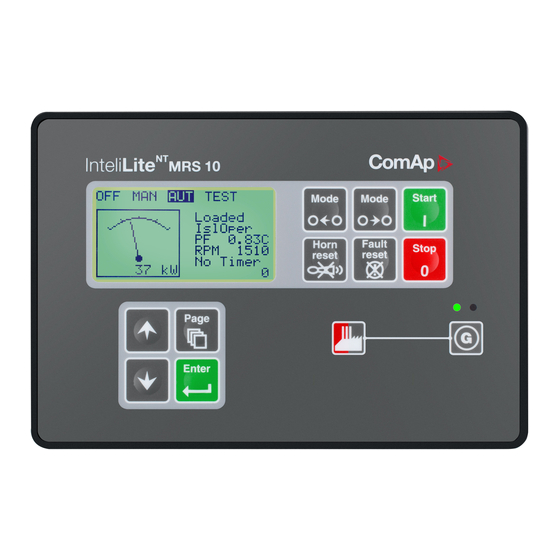
InteliLite
InteliLite MRS
(IL-CU MRS10/11/15/16) : 3 ? 3 3 ( ) 3 ? 4 iGL — RA15 4 iG
IOM/PTM 4 5 IL-CU 5 6 7 MRS 7 8 8 12 12 ( CAN) 17 18 IL-CU 18 18
IL-CU 20 22 22 23 23 24 25 27 28 31 * IOM 31 * 33 , 34 34 35 J1939
36 37 37 38 — MRS10/11/15/16 38 ? 38 -
2
^ GCB /? 38 38 ? 39 ? 39 ? 39 41 42 43 43 43 44 44 (FLS) 45
(WRN) 45 SD () 45 45 46 46 47 48 LiteEdit 48 Modbus 48 48 * ISD SDN
48 * GSM 49 * SIM- 49 49 49 49 49 50 50 50 51 / 51 * RS232 51 * CAN
51 -
3
? MRS 10/11/15/16″, . ? , InteliLite MRS. : InteliLite . , . :
RS232. REMOTE START/STOP ( /) GCB / InteliLite, . InteliLite . . :
() () (MRS10 FW MRS10 HW) , . HARDWARE INCOMPATIBLE ( ). Boot
LiteEdit; . . . «Basic settings» ( ). !!! !!! ( ) InteliLite iL-MRS
. IL-MRS 15/16 . InteliLite , , . InteliLite , , . InteliLite .
InteliLite . /, . -
4
? IL MRS InteliLite iGL -RA15 MRS15/16 iG-IOM/PTM / I/O MRS15/16
AT-LINK-CONV RS232 MRS10/11 iGL — RA15 iGL-RA15 MRS15/16 CAN.
LiteEdit — RA15. / LiteEdit. RA15. iG IOM/PTM iG-IOM iGS-PTM / : 8
, 8 , 4 . MRS15/16. , iL. , iL, , PTM. IOM/PTM , . iG-IOM ( , iL) 0
-2,4 . IOM VDO- . iGS-PTM 0-250, 0-100 mV, 0-20 mA. Pt100 . PTM
VDO. iGS-PTM. -
5
-
6
CAN
-
7
MRS
CAN Volvo Scania. . .
-
8
. . , >3m. : 1.5mm2 — 36V. — 39V. InteliLite . , . :
InteliLite !! — 4A ( ). 12V InteliLite , , . 10V, 50 — 7V, . , .
:. ; I-LBA.
-
9
1 . . . ( ) — T1A. .
.
, .
: . 2,5mm2 .
-
10
.
: 2,5mm2 5A.
: !!!
-
11
. ail-. L1, L2 L3. L1l COM-.
: : 200 % : 60,0 : 1.4 1 ( — 100% IL 1.4 ). IL-CU .
LiteEdit.2,5 2. 5. L2I L3I .
-
12
. COM- . InteliLite. 120 IL-CU . 50% . COM IL. InteliLite: AI1
AI2 AI3 IL COM-.0 — 2,4 . , >3m. IL-CU . (10 6 Bar) 4-20 mA. 4-20mA/100
4-20mA/60. 50%. InteliLite. , ; 750 . , . — 750 , , 2400 . : : Bar,
VDO, 0 — 10.0 bars. 3.5 bars, — 1.2 bars. -
13
LiteEdit, Controller — Configuration Modify Oil Press. — Oil
Press ( ) : Not used ( ) () . . : : Analog () Tri-state ( ) . . «»
/ COM- . / . «Tri-state» / COM- . : Analog : (0C, %, Bar, ). . :
Bar : , . , . ,,NC» . ,,NO » . : . ,, » . InteliLite «####», .
,,Curve A» LiteEdit ( VDO ) ,,Curve B» LiteEdit B( VDO ) ,,Curve C»
LiteEdit C ( VDO ) ,,Pt1000″ PT1000 IEC 751 ,,Ni1000″ Ni1000 DIN 43
760 ,,VDO temp» VDO ,,VDO press» VDO ,,VDO level» VDO ,,4-20mA/60″
120 COM- ,,4-20mA/100″ 120 COM- : VDO — : ,,0″ -, 360 kPa, 100%, 50
C ,,1″ , 3.6 Bar ,,2″- , .0.36 MPa ,,3″ -, .0.366 MPa : 1 -
14
, Wrn () ( ), Sd () , del (Engine protection). : Wrn () (), Sd
() . . — Wrn () () Sd () , . -
15
( CAN)
CAN , ( , , ). 120 . CAN 200 . CAN . IL-CU COM. IL-CU 120 ; CAN.
IG-IOM IGS-PTM — 120 ( ). . CAN. : IOM, PTM, . IL-CU IG-IOM IL-CU
IGS-PTM IL-CU IGL-RA15 IL-CU IG-IOM IGL-RA15 IL-CU IGS-PTM IGL-RA15
IL-CU IG-IOM IGS-PTM IGL-RA15. -
16
: IL-CU LiteEdit. 1 . IL-CU BI1 / BI2 BI3 BI4 OFF () BI5 BI6 , .
: . . , , EMERGENCY STOP » «. , , . : SprinklActive ( ) , , . , ,
(OFF—TEST) . : . . (OFF) iL OFF () ( : OFF—TEST). . : . Start ,
Start InteliLite. (). -
17
Stop , Stop InteliLite. (). FaultRes ( ) , FaultRes InteliLite.
Res ( ) , HornRes InteliLite. ^ GCB , GCB InteliLite. (). , . , —
OFF (). , Stop . «Sd () Stop » . «Emerg Man» ( ) . , . , , . , /. ,
() MODE (). , . IL-CU BO1 ( ) BO2 ( ) BO3 GCB / BO4 BO5 BO6 . , ,
. -
18
. , : , / . /, 30 /. . /. () . . / / . , . , 2 / . GCB / MRS11,
16: . MRS10 15 ( GCB/ GCB): ( () , MinStabtime elapsed, . GCB . GCB
() . GCB UV . *AnInIOM14 Wrn () , IOM/PTM. , , FAULT RESET
*AnInIOM14 Sd () , IOM/PTM. , , FAULT RESET Prestart. , . : / = 0,
: Poil, D+ ( ). OK -
19
iL. , . , . , FAULT RESET / . , . : FAULT RESET HORN RESET (Horn
timeout) / . , : OFF () , . GCB . , , . 10 / < 2 < 10 VAC,
< : . MainsParams OK IL. , . ChrgAlternFail , , D+ . , , FAULT
RESET : D+ 80% . Vgen , / . . . , , FAULT RESET Fgen , / . . ,
FAULT RESET -
20
, . , , FAULT RESET , , , . 60 . , , FAULT RESET , . . , , FAULT
RESET , . . , , FAULT RESET , . , , FAULT RESET , : * , . . , ,
FAULT RESET , iL (, — ). , , FAULT RESET V , / . , , FAULT RESET
Wrn () . , FAULT RESET Sd () , . , No Sd ( ) FAULT RESET , . . , No
warning ( ) FAULT RESET -
21
, . . , , FAULT RESET Wrn () , . . , , FAULT RESET Water Temp (
) , . . , , FAULT RESET Water Temp Wrn ( ) , . . , , FAULT RESET
OFF () , OFF () . () , () . () , () . FuelLevel ( ) , .
FuelLevelWrn ( ) , . . , . , . . , , FAULT RESET BI16 stat ()
*BI18IOM — . , , , . , FAULT RESET , , . CommOK ####, . , . -
22
PwrRelay ( ) , . YellowLamp ( ) . RedLamp ( ) . CtrlHeartBeat ()
. 500ms : 500ms. . Stop Pulse ( ) 1 Stop solenoid. . CommError
CommOK, .. , , , #####. . -
23
0 — 2400 . , bar, C ( F) %. . 2.0 : . VDO — 0 — 10.0 bars. . t
VDO — 0 — 100 C. . VDO — 0-180R = 0-100% 4 . . ENTER. ENTER. : . ,
InteliLite . 14 LiteEdit. [kW] :1kW : 1 4000 kW [ A ] It is *IDMT ,
. : *2INo m del, Ishort. . :1 A : 1 — 5000 A CT Ratio [/5A] . -
24
:1 A : 1 5000 A / 5A *PT [/1] :0,1 V / V : 0,1 500,0 V / V [V] (
— ) :1V : 100 300 V [Hz] ( 50 60 Hz ) :1Hz : 45 65 Hz [-] — , , .
0, . . :1 :0 500 : , ( 5V) . /[/] . :1 / :100 4000 / FltRes
[ENABLED ()/ ()] (): () . ENABLED (): (o TEST) () . . TO[min] . :1
min :0 60 min : 0 , . [OFF, , ] , MODE. : . * RS232
[STANDARD/MODBUS/CumminsMB] . Standard: LiteEdit. -
25
Modbus: Modbus. CumminsMB: Cummins Modbus. : . Modbus. *- AA [ —
] — . :1 : 1 30 : — . . Start /[%] , iL ( ). :1% / :5 50 % POil
[Bar] ( ). :0,1 bar :-10,0 1000,0 : ( ) : /, POil and D+ ( ). , .
[s] PRE-START . 0, PRE-START . :1s :0 600 s MaxCrank time [s] . :1s
:1 60 s CrnkFail pause[s] . :1s :5 60 s Crank attemps [-] :1 :1 10
time[s] , / /. , / 2. -
26
/NOMINAL , , . /NOMINAL . : 1 s : 0 600 s : , 5s , . Min stab
time [s] / GCB. :1s :0 300 s Max stab time [s] . :1s :0 300 s : Max
stab time, ( ). Stop time [s] . . :1s :0 600 s : , : / =0, <
POil < 10 VAC. , , , /=0, > 10V. [s] . :1s :0 3600 s [
NOMINAL / ] /NOMINAL. NOMINAL : , . : . : /NOMINAL . . Fuel
solenoid [ DIESEL / GAS ] FUEL SOLENOID ( ).. DIESEL: 1 STARTER. .
GAS: IGNITION (), / 30 / ( ). -
27
. D+ function [ENABLED ()/CHRGFAIL/ ()] ENABLED (): D+ , .
CHRGFAIL: D+ . (): D+ . : . D+ . FreqSelect
[PRIMARY/SECONDARY/DEFAULT] (// ) Volvo Scania. Volvo
«Volvo-MarineD12 Aux» : VP Status. Scania «Scania S6 Singlespeed» :
1 2 DLN1, , .. /No minal (/) . ( ), FreqSelect . Eng prot del[s] (
) (, ). . Start /. :1s : 0 300 s Horn timeout[s] ( ) . 0, HORN .
:1s : 0 600 s [%] . :1% / : 100 150% AnlInp1 level1[ Bar] 1 : 0,1
bar : AnlInp1 level2 10000 AnlInp1 level2[ Bar] 1 : 0,1 bar : -100
AnlInp1 level1 -
28
AnlInp1 del[s] 1 : 1 s : 0 180 s AnlInp2 level1[ ] 2 : 1 C :
-100 Anlinp2 level2 AnlInp2 level2[ ] 2 : 1 C : AnlInp2 level1
10000 AnlInp2 del[s] 2 : 1 s : 0 180 s AnlInp3 level1[ ] 2 : 1 % :
AnlInp3 level2 10000 AnlInp3 level2[ ] 3 : 1 % : -100 AnlInp3
level1 AnlInp3 del[s] 3 : 1 s : 0 180 s Batt undervolt[V] ( ) .
:0,1 V :8V Batt undervolt Batt overvolt [V] ( ) : :0,1 V :Batt
overvoltage 40 V del [s] . :1s :0 600 s NextServTime[h] . 0 . :1 :0
65535h -
29
: . [%] (% ) :1% :0 200% del[s] . :0.1s :0 60.0 s Ishort[ % ] ,
. :1 % :100 — 500 % *2INo m del[ s ] IDMT. 2INo m del IDMT 200% .
Igen = 2* . :0,1 s : 0,1 — 20 s IDMT . , :2INo m del * Reaction time =
Igen — : 900 sec = 15 minutes. IDMT 15 . Igen . . 200% — 2INo m
del.200% =
2INo m del 100% 101% 110%
0,2 20 2 2 200 20
20 ( >900 )
200
-
30
Curr unbal[%] (). :1% : 1 200% Curr unbal del [s] :0.1 s : 0
60.0 s >V Sd ()[%] . . . :1% : -
31
. :0.1s : 0 60.0 s >f[%] . :0.1% :
-
32
AnlInIOM2 lev1[ ] IOM 2 — . :1 : -100 — +10000 AnlInIOM2 lev2[ ]
IOM 2 — . :1 : -100 — +10000 AnlInIOM2 del [s] IOM 2. :1 s : 0 —
180 s AnlInIOM3 lev1[ ] IOM 3 — . :1 : -100 — +10000 AnlInIOM3
lev2[ ] IOM 3 — . :1 : -100 — +10000 AnlInIOM3 del [s] IOM 3. :1 s
: 0 — 180 s AnlInIOM4 lev1[ ] IOM 4 — . :1 : -100 — +10000
AnlInIOM4 lev2[ ] IOM 4 — . :1 : -100 — +10000 AnlInIOM4 del [s]
IOM 4. :1 s : 0 — 180 s IOM/PTM . CalibrAInIOM 1,2,3,4 [.] IOM/PTM.
. :1 : -1000 +1000 -
33
* — CAN bus/RS232 LiteEdit, (iG-IOM, iGL-RA15). ECU LiteEdit
(version 2.0 ) , /. /: Standard J1939 engines Scania S6
Cummins-MODBUSCummins RS232, : RS232 = CUMMINSMB. . , , . ####, . CommOK , ..
, . PwrRelay , . CAN (Volvo Scania). J1939 . , ( ) J1939 Scania
J1939 Scania S6, / : 5.2.1.9 ( 5.3.7 EEC1) 5.2.5.28 ( 5.3.29 Engine
Fluid Level/Pressure) -
34
5.2.5.5 ( 5.3.28 Engine Temperature) 5.2.5.61 — ( 5.3.19 Engine
Hours, ) 5.2.1.7 ( 5.3.6 EEC2) 5.2.5.63 ( 5.3.32 Fuel EcoNo my)
5.2.5.36 ( 5.3.36 Inlet/Exhaust Conditions) 5.2.5.4 1 ( 5.3.36
Inlet/Exhaust Conditions) Cummins MODBUS «Cummins-Modbus», (
QSX15,QSK45, QSK60): (Register Address:30001) (Register
Address:30003) (Register Address:30002) — (Register
Address:30008-30009) (Register Address:30018) (Register
Address:30530 (QSK45, QSK60 only)) (Register Address:30531 (QSK45,
QSK60 only)) — Standard J1939 SPN (Suspect Parameter Number ), FMI
( ) OC ( ); . SPM/FMI : SAE Truck and Bus Control and
Communications Network Standards Manual, SAE HS-1939 Publication .
: SPN:100 SPN:102 SPN:105 SPN:110 SPN:175 SPN:629 1 SPN:636 SPN:637
— SPN:651 #1 SPN:652 #2 SPN:653 #3 SPN:654 #4 SPN:655 #5 SPN:656 #6
SPN:677 SPN:1485 Scania: FC:1000-1001 FC:1100-1107 1 FC:1200-1207 2
FC:2000-2002 FC:2100-2102 FC:2200-2202 FC:2400-2403 FC:2600-2601 1
FC:2700-2701 2 -
35
FC:2800-2802 FC:3200-3205 FC:4300-4303 ( ) FC:6200-6201
FC:6400-6401 FC:6600-6601 FC:6A00-6A01 FC:B000-B001 FC:B100-B101
FC:B200 FC:B300 FC:C000-C006 PDE1 FC:C100-C106 PDE2 FC:C200-C206
PDE3 FC:C300-C306 PDE4 FC:C400-C406 PDE5 FC:C500-C506 PDE6
FC:C600-C606 PDE7 FC:C700-C706 PDE8 FC:E200 FC:E600 , , , , . , / ,
, IG-IOM/IGS-PTM. InteliLite, , . -
36
J1939
(, , ) 10% . — bar, oC, %. , . ( ENTER) . AI1 (AI2).
, CAN:
-
37
: iL-CU — 70 C, 73 C. AI1 +3 C ( ENTER) InteliLite (, .5) . (,
70 C -> 73 C, 5 C -> 6 C). : (, 80C, 4.0 Bar ..) 1: 6 points
VDO characteristic, pressure bar 2: 10 points VDO characteristic,
temperature C 3: 2 points VDO fuel level sensor, 0% = 10 , 100% =
180 -
38
. , MRS10/11/15/16
1 MODE > (OFF -> -> ) 2.MODE < ( -> ->OFF ) 3
HORN RESET — 4 FAULT RESET 5 START 6 STOP — 7. 8 GCB ON/OFF^ — 9
PAGE (MEASUREMENT->ADJUSTEMENT) ( ) 10 , 11 , 12 ENTER 13. 14.
15 GEN VOLTAGE PRESENT: , 16 GEN-SET FAILURE: , . FAULT RESET ( ) (
) 17 ^GCB ON: , GCB . GCB /. ? MODE: ( ) -
39
^ GCB ON/OFF (/)? (AUTO) . (MAN) , . . : MEASUREMENT ()
ADJUSTMENT (). -. PAGE. ? 1 PAGE MEASUREMENT (). 2 . ? 1 PAGE
ADJUSTMENT (). 2 . 3 ENTER. 4 . 5 «*» . 6 ENTER. 7 . . 8 ENTER;
PAGE . 9 PAGE . ? ENTER +/- . MEASUREMENT. ? ENTER, PAGE.
InteliLite INFO (10 ). InteliLite INFO : 1) 2) InteliLite (8 ) 3) .
4) Application: MRS16 5) Branch:Standard : MEASUREMENT. , ? —
MEASUREMENT. -
40
MEASUREMENT . . : Versions 1.4 and lower Version 2.0 and higher
Description Wrn () * Wrn () Active No t accepted Wrn () Wrn ()
Active accepted Wrn () * Wrn () Inactive No t accepted Inactive
accepted FAULT RESET, . . , MEASUREMENT. : , . AMF25 Control
LiteEdit. .1 2 , (L) (!) 3 4. 5 / 6 7 8 (, , .) V1-2, V2-3, V3-1 ph-ph V1,
V2, V3 ph-N (triple bargraph) I1, I2, I3 (triple bargraph) IL-CU (
) -
41
( ) ( ) ( ) IL-CU BI1 — BI6 IL-CU BO1 — BO6 : / , . * : / , . (
) ( ) ( ) ( ) — *- kWh () * kVAh () NextServTime * . J1939 ( SPN (
), FMI ( ) OC ( Occurrence Counter). . . , SPN ( ). EngOilPress WRN
() BoostPress FLS EngOilTemp FLS 629(275h) FLS Controller#1
EngCoolTemp WRN () -
42
SPN:110 OC:7 FMI:3 : FMI = 0 1, WRN (). FMI FLS.
NEXT SCREEN ENTER PAGE
-
43
OFF () No start is possible Outputs STARTER, GCB / and FUEL
SOLENOID are Not energized. No reaction if buttons START,STOP,^GCB
ON/OFF are pressed. . . MAN () START . ^GCB ON/OFF GCB. GCB, . ,
GCB ON/OFF STOP — . : . MAN () . , REM START/STOP . — () MODE = (
START STOP / ) MODE = ( REM START/STOP) StateConditionAction Next
state Start request PRESTART on Prestart / > 2 GenStop (Stop
fail)> 10V OFF () / < 2, , Vgen < 10V, Prestart 3 STARTER
Cranking () FUEL SOLENOID on 4 MaxCrank time counter started
Cranking3 /> Start / STARTER off PRESTART off D+ STARTER off
Cranking > 25% VgNom PRESTART off StateCondition of the
transition ActionNext state MaxCrank time elapsed, 1st
attemptSTARTER off Crank pause ( ) FUEL SOLENOID off STOP SOLENOID
on CrankFail pause timer started () MaxCrank time elapsed, last
attemptSTARTER off (Start fail) PRESTART off CrankCrankFail pause
elapsed STARTER on Cranking pause3FUEL SOLENOID on 4 STOP SOLENOID
off MaxCrank time counter started -
44
380% speed reached TO LOAD on 1Running Min, MaxStabTime counter
started / = 0 or any other condition FUEL SOLENOID off STOP
SOLENOID on 60 sec Elapsed FUEL SOLENOID off (Start fail) STOP
SOLENOID on RunningStop request TO LOAD offCooling Cooling time
timer started / = 0 or any other condition TO LOAD off 2 FUEL
SOLENOID off GCB / closed ed GCB / openedRunning / = 0 condition
FUEL SOLENOID off STOP SOLENO ID on TO LOAD off CoolingCooling time
elapsedFUEL SOLENOID offStop STOP SOLENOID on / = 0 or any other
condition FUEL SOLENOID off STOP SOLENOID on Start 1Running Stop/ =
0, , Vgen -
45
Warning (WRN ()) When warning comes up, only outputs and common
warning output are closed. Possible warnings: See List of possible
events (SD (HORN) ) InteliLite GCB /, FUEL SOLENO ID, STARTER
PRESTART . InteliLite , / . : InteliLite : L1, L2, L3. (, L1,L3,L2
L2,L1,L3), : G ph opposed = // OK, 180. : GEN L1 neg= L1 GEN L2
neg= L2 GEN L3 neg= L3 . . G ph+L1 neg = 1L1 G ph+L2 neg = 1L1 G
ph+L3 neg = 1L1 : , >50VAC 120 20. 1 . Fls , 6,2% . ####. :
Ready -
46
Prestart . . Cranking Pause , Running , GCB OPEN/CLOSE Stop ,
Ready Cooling Oil Press Wrn () WRN () YES . Oil Press Sd () SD
(HORN) NO Water Temp Wrn () WRN () YES . Water Temp Sd () SD
(HORN)NO . Fuel Level Wrn () WRN () YES . Fuel Level Sd ()SD
(HORN)NO . Analog inp IOM/PTM — Wrn ()WRN () YES IG-IOM/IGS-PTM.
Analog inp IOM/PTM — Sd ()SD (HORN) YES IG-IOM/IGS-PTM. YES
eWarning/ IL-CU. WRN () YES / Battery flat SD (HORN) YES — , .
Start failure SD (HORN) YES . ParamFailNONE NO Happends Vgen SD
(HORN) YES s. Vgen unblSD (HORN) NO , . Fgen SD (HORN)YES . Igen
unblSD (HORN) NO 0 . SD () YES . SD () YES , , . SD ()YES , — / , .
. Emergency Stop SD () NO , . PickupFault SD () NO . Stop failSD ()
YES . Wrn () ServiceTimeWRN () NO . , — . ChrgAlternFailWRN () YES
. SprinklActive WRN () NO , . *Wrn () RA15 failWRN () IGL-RA15. -
47
*Sd () IOM failSD NO IG-IOM/IGS- PTM. Wrn () NO . InteliLite
RS232. ** iL MRS15/16 RS232. ** iL MRS10/11 RS232 AT-LINK-CONV ( )
. : , COM- ( DC- ) . , . 240/20 ( GND () ).5 — GND () 2 — RxD 3 — TxD 5 — GND () 2 — RxD 3 — TxD 230 . 0 .
GND () RS 232 . — LiteEdit ( ) LiteEdit ComAp ( Windows 95 ).
LiteEdit : * Modbus iL RS232 -
48
9600 bps, 8 data bits, 1 stop bit, No parity RTU 3 ( Read
Multiply Registers) 6 ( — Write Single Register) 16 ( — Write
Multiply Registers) 4.096 ms . Modbus Modbus Protocol Reference
Guide PI-MBUS-300 Open Modbus Specification Release 1.0. t
http://www.modicon.com/openmbus/ . , , . 16- . , Modbus, 16- . . .
. : , IL , LiteEdit. * ISD SDN Askey TAS-200E ASUScom TA-220ST *
GSM Wavecom M1200 ( WMOD2; baud rate to 9600 bps) Siemens M20
Siemens TC35 FALCOM A2D GSM GSM . AT GSM IL-. LiteEdit: MS
Windows-Start-Program files — LiteEdit Gm_setup.exe. COM port iG-CU
(=IS-CU) iG-MU Setup GSM odem Setup baud rate GSM — 80 — 90 Bps. :
(IL ) . * Mobile SIM- SIM- GSM : ( ) PIN- 8-36 . -
49
0,5-0,1A . : 50ms 10, . 8 ( InteliLite 3.2 ). 2 % 24. : 7 .
IL-CU -20..+700C IL-CU-LT# -30..+700C -30..+800C IP65 95% : Low
Voltage Directive EN 61010-1:95 +A1:97 Electromagnetic
Compatibility EN 50081-1:94, EN 50081-2:96 EN 50082-1:99, EN
50082-2:97 5 — 25 Hz, 1,6mm 25 — 100 Hz, a = 4 a = 200 m/s2 # —
200C — + 700C, . InteliLite LT , . foil 50C, . IL-CU Standard Order
code:IL-CU-LT -200C..+700C -300C..+700C -300C..+800C -300C..+800C .
00C -150C -300C 12VDC 360 mA +50 mA +180 mA +300 mA 24VDC 230 mA
+25 mA +85 mA +150 mA 36VDC 100 mA +20 mA +65 mA +100 mA -300C
InteliLite LT , . (., ) . 180x120x55 800 50-60Hz 0,2% ( CT) 5 A ( )
< 0,1 < 0,2 VA (In=5A) 10 A 2% 150 A / 1 -
50
. 12 A 231 (-) 400 () 290 (-) 0,6M (-) 0,3 M (-) 2 % — III
(EN61010) 6 4,7k 0-36 . 0-2 V 8-36 V 2 — 100 000 12 A DC4 A DC 36 . 24 V / 0,1 A 500 Veff o 4 0,5 A 36 . 10 0 — 2,4 k 4
% — ( ) 2 Vpk-pk ( 4 — 4 ) 50 Veff 4 10 k ( 6Vpk-pk) 0,2 % * RS232
10 19.2kBd (STD) 9.6kBd (MODBUS) : ADVANTECH ADAM 4520: RS232 to
RS422/485 converter, DIN rail, automatic RS485 bus supervision, No
external data flow control signals, galvanic isolated. : ADVANTECH
PCL-745B or PCL745S : Dual port RS422/485 Interface card, automatic
RS485 bus supervision, No external data flow control signals,
galvanic isolated * CAN CAN 200 -
51
250kBd 120 : () , , CAN 200 iS-COM: min. 75% (max. 4,4 ns/m)
.0,25 2 ( 1 ) 2 dB / 100 : BELDEN (see http://www.belden.com):
3082A DeviceBus for Allen-Bradley DeviceNet 3083A DeviceBus for
Allen-Bradley DeviceNet 3086A DeviceBus for Honeywell SD (HORN)S
3087A DeviceBus for Honeywell SD (HORN)S 3084A DeviceBus for
Allen-Bradley DeviceNet 3085A DeviceBus for Allen-Bradley DeviceNet
3105A Paired EIA Industrial RS485 cable LAPP CABLE (see
http://www.lappcable.com) Unitronic BUS DeviceNet Trunk Cable
Unitronic BUS DeviceNet Drop Cable Unitronic BUS CAN Unitronic-FD
BUS P CAN UL/CSA -
52
( ) (MRS10/11/15/16): . . InteliLite IL-2.1 MRS16 30.11.2004 2,1
0200FFFF MRS16-R:10.11.2004 2.1.ail InteliLiteNo 8637 Short string
200 kW No 82761 4000 16 350 ANo 827515000 16 CT 2000 /5A No 82741
5000 16 PT 1,0 /1No 9579 0,1500,0 16 231 VNo 827710022000 16 50 Hz
No 8278 45 65 16 120No 82520500 16 / 1500 / No 8253100 4000 16
FltRes No 9983 String list TO0 min No 101210 60 8 OFFNo 8315 String
list RS232 STANDARD Yes 24522String list — AA3 Yes24512 130 8
Engine params / 25 %No 8254550 8 Engine params POil4,5 Bar No 9681
-10,0 1000,0 Integer 16 Engine params 2 s No 83940600 16 Engine
params MaxCrank time 5 s No 8256 160 8 Engine params CrnkFail pause
8 s No 8257 560 8 Engine params Crank attempts 3 No 8255 110 8
Engine params time 12 s No 9097 0 600 16 Engine params Min stab
time 2 sNo 8259 0300 16 Engine params Max stab time 10 s No 8313 0
300 16 Engine params Stop time 60 s No 9815 0 600 16 Engine params
Cooling time 30 s No 8258 03600 16 Engine params Cooling speed No
10046 String list Engine params Fuel sole No I dDIESEL No 9100
String list Engine params D+ function No 9683 String list Engine
params FreqSelectPRIMARY No 10266 String list Engine protect Eng
prot del 5 s No 8262 0 300 16 Engine protect timeout1 0 s No 8264 0
600 16 Engine protect 115 % No 826350 150 16 Engine protect AnlInp1
level1 2,0 Bar No 83691,0 1000,0 Integer 16 Engine protect AnlInp1
level2 1,0 Bar No 8370 -10,02,0 Integer 16 Engine protect AnlInp1
del 3 s No 8365 0 180 16 Engine protect AnlInp2 level1 80 C No 8375
-10090 Integer 16 Engine protect AnlInp2 level2 90 C No 83768010000
Integer 16 Engine protect AnlInp2 del 5 s No 8371 0180 16 Engine
protect AnlInp3 level1 20 % No 83811010000 Integer 16 Engine
protect AnlInp3 level2 10 % No 8382 -10020 Integer 16 Engine
protect AnlInp3 del 10 s No 8377 0 180 16 Engine protect Batt
overvolt 36,0 V No 9587 18,040,0 Integer 16 Engine protect Batt
undervolt 18,0 V No 83878,036,0 Integer 16 Engine protect del 5 s
No 8383 0 600 16 Engine protect 65534 h No 9648 065535 16 Gener
protect 120 % No 82800200 16 -
53
Gener protect del 5,0 s No 82810,060,0 16 Gener protect Ishort
250 % No 8282100 500 16 Gener protect 2INo m del 4,0 s No
82830,120,0 16 Gener protect Curr unbal 50 % No 82841200 16 Gener
protect Curr unbal del 5,0 s No 8285 0,060,0 16 Gener protect >V
Sd () 110 % No 8291 70 200 16 Gener protect f1 10,0 % No
829685,0200,0 16 Gener protect -
54
L30 kW8526 Integer 16 kVAr08203 Integer 16 L1 08527 Integer 16
L2 08528 Integer 16 L3 08529 Integer 16 0 kVA 8565 Integer 16 L1 0
kVA 8530 Integer 16 L2 0 kVA 8531 Integer 16 L3 0 kVA 8532 Integer
16 0,008204 Integer 8 L10,008533 Integer 8 L20,008534 Integer 8
L30,008535 Integer 8 8395 18626 28627 38628 0,0 Hz 8210 16 V L1-N0
V8192 16 V L2-N0 V8193 16 V L3-N0 V8194 16 V L1-L20 V9628 16 V
L2-L30 V9629 16 V L3-L10 V9630 16 L10 A8198 16 L20 A8199 16 L3 0 A
8200 16 I/O BInpIL001000 8235 16 -
55
I/O BOutIL000001 8239 16 Statistics kWhours08205 Integer 32
Statistics kVArhours08539 Integer 32 Statistics NumStarts08207 16
Statistics RunHours 0 h 8206 Integer 32 Statistics NextServTime
65534 h9648 16 IL info TimerText 8954 16 IL info TimerValue0 s 8955
16 IL info SW version2,18393 8 IL info SW branch18707 8 IL info
Application 48480 8 IL info 09651 8 IL info DiagData 0 10050 32 IL
info PasswordDecode2481875985 9090 32 RA15 module
BOutRA150000000000000009849 16 IOM/PTM module AnInIOM 1 0 U48978
Integer 16 IOM/PTM module AnInIOM 2 0 U58759 Integer 16 IOM/PTM
module AnInIOM 3 0 U68760 Integer 16 IOM/PTM module AnInIOM 4 0
U78761 Integer 16 IOM/PTM module BInpIOM000000008602 16 IOM/PTM
module BOutIOM 00000000 8604 16 Fuel rate ##### L/h9860 16 ##### C
9855 Integer 16 ManifoldTemp ##### C 9878 Integer 16 ##### Bar 9929
16 Boost pressure0,0 Bar 9877 8 PercAtCS0 % 9925 8
-
Contents
-
Table of Contents
-
Bookmarks
Quick Links
NT
InteliLite
InteliLite NT
Modular Gen-set Controller
Compact Controller for Stand-by Operating Gen-sets
(IL-NT-MRS3,4-AMF8,9)
SW version 1.4, October 2008
Copyright © 2008 ComAp s.r.o.
Written by Petr Novák
Prague, Czech Republic
®
MRSx AMFx
ComAp, spol. s r.o.
Kundratka 2359/17, 180 00 Praha 8, Czech Republic
Tel: +420 2 66316661, Fax: +420 2 66316647
E-mail: info@comap.cz, www.comap.cz
Reference Guide
Related Manuals for ComAp IL-NT MRS15
Summary of Contents for ComAp IL-NT MRS15
Following alarms are available:
•
Sensor Fail
•
Warning
•
Shut down
•
^Mains failure
Sensor Fail (FLS)
Sensor Fail is detected when measured value is 6% out of selected sensor characteristic, or data from
ECU is missing. Sensor Fail is indicated by ##### symbol instead measured value.
Warning (WRN)
When warning comes up, only alarm outputs and common warning output are closed.
Possible warnings:
See
List of possible events
Shut down (SD)
When the shut-down alarm comes up, InteliLite opens outputs GCB CLOSE/OPEN, FUEL
SOLENOID, STARTER and PRESTART to stop the engine immediately. Alarm outputs and common
shutdown output are closed. Active or not reset protection disables start.
Possible shut-down alarms:
See
List of possible events
^Mains failure (MF)
Mains failure detection depends on AMF Settings setpoints (levels and delays) adjusting. When the
mains failure comes up, mains circuit breaker is opened. This alarm occurs only in AMF8 and AMF9
Possible mains failure reasons:
See List of possible events
Hint:
Mains failure is not written to alarm list!
NT
InteliLite
– MRS3,4, AMF8,9, SW version 1.4, ©ComAp – October 2008
IL-NT-MRS3,4-AMF8,9-1.4-Reference Guide.pdf
44
Описание на модульный контроллер ComAp MRS10-11-15-16Это описание очень хорошо описывает модуль контроля CompApMRS10-11-15-16
-
InteliLite
InteliLite MRS
(IL-CU MRS10/11/15/16) : 3 ? 3 3 ( ) 3 ? 4 iGL — RA15 4 iG
IOM/PTM 4 5 IL-CU 5 6 7 MRS 7 8 8 12 12 ( CAN) 17 18 IL-CU 18 18
IL-CU 20 22 22 23 23 24 25 27 28 31 * IOM 31 * 33 , 34 34 35 J1939
36 37 37 38 — MRS10/11/15/16 38 ? 38 -
2
^ GCB /? 38 38 ? 39 ? 39 ? 39 41 42 43 43 43 44 44 (FLS) 45
(WRN) 45 SD () 45 45 46 46 47 48 LiteEdit 48 Modbus 48 48 * ISD SDN
48 * GSM 49 * SIM- 49 49 49 49 49 50 50 50 51 / 51 * RS232 51 * CAN
51 -
3
? MRS 10/11/15/16″, . ? , InteliLite MRS. : InteliLite . , . :
RS232. REMOTE START/STOP ( /) GCB / InteliLite, . InteliLite . . :
() () (MRS10 FW MRS10 HW) , . HARDWARE INCOMPATIBLE ( ). Boot
LiteEdit; . . . «Basic settings» ( ). !!! !!! ( ) InteliLite iL-MRS
. IL-MRS 15/16 . InteliLite , , . InteliLite , , . InteliLite .
InteliLite . /, . -
4
? IL MRS InteliLite iGL -RA15 MRS15/16 iG-IOM/PTM / I/O MRS15/16
AT-LINK-CONV RS232 MRS10/11 iGL — RA15 iGL-RA15 MRS15/16 CAN.
LiteEdit — RA15. / LiteEdit. RA15. iG IOM/PTM iG-IOM iGS-PTM / : 8
, 8 , 4 . MRS15/16. , iL. , iL, , PTM. IOM/PTM , . iG-IOM ( , iL) 0
-2,4 . IOM VDO- . iGS-PTM 0-250, 0-100 mV, 0-20 mA. Pt100 . PTM
VDO. iGS-PTM. -
5
-
6
CAN
-
7
MRS
CAN Volvo Scania. . .
-
8
. . , >3m. : 1.5mm2 — 36V. — 39V. InteliLite . , . :
InteliLite !! — 4A ( ). 12V InteliLite , , . 10V, 50 — 7V, . , .
:. ; I-LBA.
-
9
1 . . . ( ) — T1A. .
.
, .
: . 2,5mm2 .
-
10
.
: 2,5mm2 5A.
: !!!
-
11
. ail-. L1, L2 L3. L1l COM-.
: : 200 % : 60,0 : 1.4 1 ( — 100% IL 1.4 ). IL-CU .
LiteEdit.2,5 2. 5. L2I L3I .
-
12
. COM- . InteliLite. 120 IL-CU . 50% . COM IL. InteliLite: AI1
AI2 AI3 IL COM-.0 — 2,4 . , >3m. IL-CU . (10 6 Bar) 4-20 mA. 4-20mA/100
4-20mA/60. 50%. InteliLite. , ; 750 . , . — 750 , , 2400 . : : Bar,
VDO, 0 — 10.0 bars. 3.5 bars, — 1.2 bars. -
13
LiteEdit, Controller — Configuration Modify Oil Press. — Oil
Press ( ) : Not used ( ) () . . : : Analog () Tri-state ( ) . . «»
/ COM- . / . «Tri-state» / COM- . : Analog : (0C, %, Bar, ). . :
Bar : , . , . ,,NC» . ,,NO » . : . ,, » . InteliLite «####», .
,,Curve A» LiteEdit ( VDO ) ,,Curve B» LiteEdit B( VDO ) ,,Curve C»
LiteEdit C ( VDO ) ,,Pt1000″ PT1000 IEC 751 ,,Ni1000″ Ni1000 DIN 43
760 ,,VDO temp» VDO ,,VDO press» VDO ,,VDO level» VDO ,,4-20mA/60″
120 COM- ,,4-20mA/100″ 120 COM- : VDO — : ,,0″ -, 360 kPa, 100%, 50
C ,,1″ , 3.6 Bar ,,2″- , .0.36 MPa ,,3″ -, .0.366 MPa : 1 -
14
, Wrn () ( ), Sd () , del (Engine protection). : Wrn () (), Sd
() . . — Wrn () () Sd () , . -
15
( CAN)
CAN , ( , , ). 120 . CAN 200 . CAN . IL-CU COM. IL-CU 120 ; CAN.
IG-IOM IGS-PTM — 120 ( ). . CAN. : IOM, PTM, . IL-CU IG-IOM IL-CU
IGS-PTM IL-CU IGL-RA15 IL-CU IG-IOM IGL-RA15 IL-CU IGS-PTM IGL-RA15
IL-CU IG-IOM IGS-PTM IGL-RA15. -
16
: IL-CU LiteEdit. 1 . IL-CU BI1 / BI2 BI3 BI4 OFF () BI5 BI6 , .
: . . , , EMERGENCY STOP » «. , , . : SprinklActive ( ) , , . , ,
(OFF—TEST) . : . . (OFF) iL OFF () ( : OFF—TEST). . : . Start ,
Start InteliLite. (). -
17
Stop , Stop InteliLite. (). FaultRes ( ) , FaultRes InteliLite.
Res ( ) , HornRes InteliLite. ^ GCB , GCB InteliLite. (). , . , —
OFF (). , Stop . «Sd () Stop » . «Emerg Man» ( ) . , . , , . , /. ,
() MODE (). , . IL-CU BO1 ( ) BO2 ( ) BO3 GCB / BO4 BO5 BO6 . , ,
. -
18
. , : , / . /, 30 /. . /. () . . / / . , . , 2 / . GCB / MRS11,
16: . MRS10 15 ( GCB/ GCB): ( () , MinStabtime elapsed, . GCB . GCB
() . GCB UV . *AnInIOM14 Wrn () , IOM/PTM. , , FAULT RESET
*AnInIOM14 Sd () , IOM/PTM. , , FAULT RESET Prestart. , . : / = 0,
: Poil, D+ ( ). OK -
19
iL. , . , . , FAULT RESET / . , . : FAULT RESET HORN RESET (Horn
timeout) / . , : OFF () , . GCB . , , . 10 / < 2 < 10 VAC,
< : . MainsParams OK IL. , . ChrgAlternFail , , D+ . , , FAULT
RESET : D+ 80% . Vgen , / . . . , , FAULT RESET Fgen , / . . ,
FAULT RESET -
20
, . , , FAULT RESET , , , . 60 . , , FAULT RESET , . . , , FAULT
RESET , . . , , FAULT RESET , . , , FAULT RESET , : * , . . , ,
FAULT RESET , iL (, — ). , , FAULT RESET V , / . , , FAULT RESET
Wrn () . , FAULT RESET Sd () , . , No Sd ( ) FAULT RESET , . . , No
warning ( ) FAULT RESET -
21
, . . , , FAULT RESET Wrn () , . . , , FAULT RESET Water Temp (
) , . . , , FAULT RESET Water Temp Wrn ( ) , . . , , FAULT RESET
OFF () , OFF () . () , () . () , () . FuelLevel ( ) , .
FuelLevelWrn ( ) , . . , . , . . , , FAULT RESET BI16 stat ()
*BI18IOM — . , , , . , FAULT RESET , , . CommOK ####, . , . -
22
PwrRelay ( ) , . YellowLamp ( ) . RedLamp ( ) . CtrlHeartBeat ()
. 500ms : 500ms. . Stop Pulse ( ) 1 Stop solenoid. . CommError
CommOK, .. , , , #####. . -
23
0 — 2400 . , bar, C ( F) %. . 2.0 : . VDO — 0 — 10.0 bars. . t
VDO — 0 — 100 C. . VDO — 0-180R = 0-100% 4 . . ENTER. ENTER. : . ,
InteliLite . 14 LiteEdit. [kW] :1kW : 1 4000 kW [ A ] It is *IDMT ,
. : *2INo m del, Ishort. . :1 A : 1 — 5000 A CT Ratio [/5A] . -
24
:1 A : 1 5000 A / 5A *PT [/1] :0,1 V / V : 0,1 500,0 V / V [V] (
— ) :1V : 100 300 V [Hz] ( 50 60 Hz ) :1Hz : 45 65 Hz [-] — , , .
0, . . :1 :0 500 : , ( 5V) . /[/] . :1 / :100 4000 / FltRes
[ENABLED ()/ ()] (): () . ENABLED (): (o TEST) () . . TO[min] . :1
min :0 60 min : 0 , . [OFF, , ] , MODE. : . * RS232
[STANDARD/MODBUS/CumminsMB] . Standard: LiteEdit. -
25
Modbus: Modbus. CumminsMB: Cummins Modbus. : . Modbus. *- AA [ —
] — . :1 : 1 30 : — . . Start /[%] , iL ( ). :1% / :5 50 % POil
[Bar] ( ). :0,1 bar :-10,0 1000,0 : ( ) : /, POil and D+ ( ). , .
[s] PRE-START . 0, PRE-START . :1s :0 600 s MaxCrank time [s] . :1s
:1 60 s CrnkFail pause[s] . :1s :5 60 s Crank attemps [-] :1 :1 10
time[s] , / /. , / 2. -
26
/NOMINAL , , . /NOMINAL . : 1 s : 0 600 s : , 5s , . Min stab
time [s] / GCB. :1s :0 300 s Max stab time [s] . :1s :0 300 s : Max
stab time, ( ). Stop time [s] . . :1s :0 600 s : , : / =0, <
POil < 10 VAC. , , , /=0, > 10V. [s] . :1s :0 3600 s [
NOMINAL / ] /NOMINAL. NOMINAL : , . : . : /NOMINAL . . Fuel
solenoid [ DIESEL / GAS ] FUEL SOLENOID ( ).. DIESEL: 1 STARTER. .
GAS: IGNITION (), / 30 / ( ). -
27
. D+ function [ENABLED ()/CHRGFAIL/ ()] ENABLED (): D+ , .
CHRGFAIL: D+ . (): D+ . : . D+ . FreqSelect
[PRIMARY/SECONDARY/DEFAULT] (// ) Volvo Scania. Volvo
«Volvo-MarineD12 Aux» : VP Status. Scania «Scania S6 Singlespeed» :
1 2 DLN1, , .. /No minal (/) . ( ), FreqSelect . Eng prot del[s] (
) (, ). . Start /. :1s : 0 300 s Horn timeout[s] ( ) . 0, HORN .
:1s : 0 600 s [%] . :1% / : 100 150% AnlInp1 level1[ Bar] 1 : 0,1
bar : AnlInp1 level2 10000 AnlInp1 level2[ Bar] 1 : 0,1 bar : -100
AnlInp1 level1 -
28
AnlInp1 del[s] 1 : 1 s : 0 180 s AnlInp2 level1[ ] 2 : 1 C :
-100 Anlinp2 level2 AnlInp2 level2[ ] 2 : 1 C : AnlInp2 level1
10000 AnlInp2 del[s] 2 : 1 s : 0 180 s AnlInp3 level1[ ] 2 : 1 % :
AnlInp3 level2 10000 AnlInp3 level2[ ] 3 : 1 % : -100 AnlInp3
level1 AnlInp3 del[s] 3 : 1 s : 0 180 s Batt undervolt[V] ( ) .
:0,1 V :8V Batt undervolt Batt overvolt [V] ( ) : :0,1 V :Batt
overvoltage 40 V del [s] . :1s :0 600 s NextServTime[h] . 0 . :1 :0
65535h -
29
: . [%] (% ) :1% :0 200% del[s] . :0.1s :0 60.0 s Ishort[ % ] ,
. :1 % :100 — 500 % *2INo m del[ s ] IDMT. 2INo m del IDMT 200% .
Igen = 2* . :0,1 s : 0,1 — 20 s IDMT . , :2INo m del * Reaction time =
Igen — : 900 sec = 15 minutes. IDMT 15 . Igen . . 200% — 2INo m
del.200% =
2INo m del 100% 101% 110%
0,2 20 2 2 200 20
20 ( >900 )
200
-
30
Curr unbal[%] (). :1% : 1 200% Curr unbal del [s] :0.1 s : 0
60.0 s >V Sd ()[%] . . . :1% : -
31
. :0.1s : 0 60.0 s >f[%] . :0.1% :
-
32
AnlInIOM2 lev1[ ] IOM 2 — . :1 : -100 — +10000 AnlInIOM2 lev2[ ]
IOM 2 — . :1 : -100 — +10000 AnlInIOM2 del [s] IOM 2. :1 s : 0 —
180 s AnlInIOM3 lev1[ ] IOM 3 — . :1 : -100 — +10000 AnlInIOM3
lev2[ ] IOM 3 — . :1 : -100 — +10000 AnlInIOM3 del [s] IOM 3. :1 s
: 0 — 180 s AnlInIOM4 lev1[ ] IOM 4 — . :1 : -100 — +10000
AnlInIOM4 lev2[ ] IOM 4 — . :1 : -100 — +10000 AnlInIOM4 del [s]
IOM 4. :1 s : 0 — 180 s IOM/PTM . CalibrAInIOM 1,2,3,4 [.] IOM/PTM.
. :1 : -1000 +1000 -
33
* — CAN bus/RS232 LiteEdit, (iG-IOM, iGL-RA15). ECU LiteEdit
(version 2.0 ) , /. /: Standard J1939 engines Scania S6
Cummins-MODBUSCummins RS232, : RS232 = CUMMINSMB. . , , . ####, . CommOK , ..
, . PwrRelay , . CAN (Volvo Scania). J1939 . , ( ) J1939 Scania
J1939 Scania S6, / : 5.2.1.9 ( 5.3.7 EEC1) 5.2.5.28 ( 5.3.29 Engine
Fluid Level/Pressure) -
34
5.2.5.5 ( 5.3.28 Engine Temperature) 5.2.5.61 — ( 5.3.19 Engine
Hours, ) 5.2.1.7 ( 5.3.6 EEC2) 5.2.5.63 ( 5.3.32 Fuel EcoNo my)
5.2.5.36 ( 5.3.36 Inlet/Exhaust Conditions) 5.2.5.4 1 ( 5.3.36
Inlet/Exhaust Conditions) Cummins MODBUS «Cummins-Modbus», (
QSX15,QSK45, QSK60): (Register Address:30001) (Register
Address:30003) (Register Address:30002) — (Register
Address:30008-30009) (Register Address:30018) (Register
Address:30530 (QSK45, QSK60 only)) (Register Address:30531 (QSK45,
QSK60 only)) — Standard J1939 SPN (Suspect Parameter Number ), FMI
( ) OC ( ); . SPM/FMI : SAE Truck and Bus Control and
Communications Network Standards Manual, SAE HS-1939 Publication .
: SPN:100 SPN:102 SPN:105 SPN:110 SPN:175 SPN:629 1 SPN:636 SPN:637
— SPN:651 #1 SPN:652 #2 SPN:653 #3 SPN:654 #4 SPN:655 #5 SPN:656 #6
SPN:677 SPN:1485 Scania: FC:1000-1001 FC:1100-1107 1 FC:1200-1207 2
FC:2000-2002 FC:2100-2102 FC:2200-2202 FC:2400-2403 FC:2600-2601 1
FC:2700-2701 2 -
35
FC:2800-2802 FC:3200-3205 FC:4300-4303 ( ) FC:6200-6201
FC:6400-6401 FC:6600-6601 FC:6A00-6A01 FC:B000-B001 FC:B100-B101
FC:B200 FC:B300 FC:C000-C006 PDE1 FC:C100-C106 PDE2 FC:C200-C206
PDE3 FC:C300-C306 PDE4 FC:C400-C406 PDE5 FC:C500-C506 PDE6
FC:C600-C606 PDE7 FC:C700-C706 PDE8 FC:E200 FC:E600 , , , , . , / ,
, IG-IOM/IGS-PTM. InteliLite, , . -
36
J1939
(, , ) 10% . — bar, oC, %. , . ( ENTER) . AI1 (AI2).
, CAN:
-
37
: iL-CU — 70 C, 73 C. AI1 +3 C ( ENTER) InteliLite (, .5) . (,
70 C -> 73 C, 5 C -> 6 C). : (, 80C, 4.0 Bar ..) 1: 6 points
VDO characteristic, pressure bar 2: 10 points VDO characteristic,
temperature C 3: 2 points VDO fuel level sensor, 0% = 10 , 100% =
180 -
38
. , MRS10/11/15/16
1 MODE > (OFF -> -> ) 2.MODE < ( -> ->OFF ) 3
HORN RESET — 4 FAULT RESET 5 START 6 STOP — 7. 8 GCB ON/OFF^ — 9
PAGE (MEASUREMENT->ADJUSTEMENT) ( ) 10 , 11 , 12 ENTER 13. 14.
15 GEN VOLTAGE PRESENT: , 16 GEN-SET FAILURE: , . FAULT RESET ( ) (
) 17 ^GCB ON: , GCB . GCB /. ? MODE: ( ) -
39
^ GCB ON/OFF (/)? (AUTO) . (MAN) , . . : MEASUREMENT ()
ADJUSTMENT (). -. PAGE. ? 1 PAGE MEASUREMENT (). 2 . ? 1 PAGE
ADJUSTMENT (). 2 . 3 ENTER. 4 . 5 «*» . 6 ENTER. 7 . . 8 ENTER;
PAGE . 9 PAGE . ? ENTER +/- . MEASUREMENT. ? ENTER, PAGE.
InteliLite INFO (10 ). InteliLite INFO : 1) 2) InteliLite (8 ) 3) .
4) Application: MRS16 5) Branch:Standard : MEASUREMENT. , ? —
MEASUREMENT. -
40
MEASUREMENT . . : Versions 1.4 and lower Version 2.0 and higher
Description Wrn () * Wrn () Active No t accepted Wrn () Wrn ()
Active accepted Wrn () * Wrn () Inactive No t accepted Inactive
accepted FAULT RESET, . . , MEASUREMENT. : , . AMF25 Control
LiteEdit. .1 2 , (L) (!) 3 4. 5 / 6 7 8 (, , .) V1-2, V2-3, V3-1 ph-ph V1,
V2, V3 ph-N (triple bargraph) I1, I2, I3 (triple bargraph) IL-CU (
) -
41
( ) ( ) ( ) IL-CU BI1 — BI6 IL-CU BO1 — BO6 : / , . * : / , . (
) ( ) ( ) ( ) — *- kWh () * kVAh () NextServTime * . J1939 ( SPN (
), FMI ( ) OC ( Occurrence Counter). . . , SPN ( ). EngOilPress WRN
() BoostPress FLS EngOilTemp FLS 629(275h) FLS Controller#1
EngCoolTemp WRN () -
42
SPN:110 OC:7 FMI:3 : FMI = 0 1, WRN (). FMI FLS.
NEXT SCREEN ENTER PAGE
-
43
OFF () No start is possible Outputs STARTER, GCB / and FUEL
SOLENOID are Not energized. No reaction if buttons START,STOP,^GCB
ON/OFF are pressed. . . MAN () START . ^GCB ON/OFF GCB. GCB, . ,
GCB ON/OFF STOP — . : . MAN () . , REM START/STOP . — () MODE = (
START STOP / ) MODE = ( REM START/STOP) StateConditionAction Next
state Start request PRESTART on Prestart / > 2 GenStop (Stop
fail)> 10V OFF () / < 2, , Vgen < 10V, Prestart 3 STARTER
Cranking () FUEL SOLENOID on 4 MaxCrank time counter started
Cranking3 /> Start / STARTER off PRESTART off D+ STARTER off
Cranking > 25% VgNom PRESTART off StateCondition of the
transition ActionNext state MaxCrank time elapsed, 1st
attemptSTARTER off Crank pause ( ) FUEL SOLENOID off STOP SOLENOID
on CrankFail pause timer started () MaxCrank time elapsed, last
attemptSTARTER off (Start fail) PRESTART off CrankCrankFail pause
elapsed STARTER on Cranking pause3FUEL SOLENOID on 4 STOP SOLENOID
off MaxCrank time counter started -
44
380% speed reached TO LOAD on 1Running Min, MaxStabTime counter
started / = 0 or any other condition FUEL SOLENOID off STOP
SOLENOID on 60 sec Elapsed FUEL SOLENOID off (Start fail) STOP
SOLENOID on RunningStop request TO LOAD offCooling Cooling time
timer started / = 0 or any other condition TO LOAD off 2 FUEL
SOLENOID off GCB / closed ed GCB / openedRunning / = 0 condition
FUEL SOLENOID off STOP SOLENO ID on TO LOAD off CoolingCooling time
elapsedFUEL SOLENOID offStop STOP SOLENOID on / = 0 or any other
condition FUEL SOLENOID off STOP SOLENOID on Start 1Running Stop/ =
0, , Vgen -
45
Warning (WRN ()) When warning comes up, only outputs and common
warning output are closed. Possible warnings: See List of possible
events (SD (HORN) ) InteliLite GCB /, FUEL SOLENO ID, STARTER
PRESTART . InteliLite , / . : InteliLite : L1, L2, L3. (, L1,L3,L2
L2,L1,L3), : G ph opposed = // OK, 180. : GEN L1 neg= L1 GEN L2
neg= L2 GEN L3 neg= L3 . . G ph+L1 neg = 1L1 G ph+L2 neg = 1L1 G
ph+L3 neg = 1L1 : , >50VAC 120 20. 1 . Fls , 6,2% . ####. :
Ready -
46
Prestart . . Cranking Pause , Running , GCB OPEN/CLOSE Stop ,
Ready Cooling Oil Press Wrn () WRN () YES . Oil Press Sd () SD
(HORN) NO Water Temp Wrn () WRN () YES . Water Temp Sd () SD
(HORN)NO . Fuel Level Wrn () WRN () YES . Fuel Level Sd ()SD
(HORN)NO . Analog inp IOM/PTM — Wrn ()WRN () YES IG-IOM/IGS-PTM.
Analog inp IOM/PTM — Sd ()SD (HORN) YES IG-IOM/IGS-PTM. YES
eWarning/ IL-CU. WRN () YES / Battery flat SD (HORN) YES — , .
Start failure SD (HORN) YES . ParamFailNONE NO Happends Vgen SD
(HORN) YES s. Vgen unblSD (HORN) NO , . Fgen SD (HORN)YES . Igen
unblSD (HORN) NO 0 . SD () YES . SD () YES , , . SD ()YES , — / , .
. Emergency Stop SD () NO , . PickupFault SD () NO . Stop failSD ()
YES . Wrn () ServiceTimeWRN () NO . , — . ChrgAlternFailWRN () YES
. SprinklActive WRN () NO , . *Wrn () RA15 failWRN () IGL-RA15. -
47
*Sd () IOM failSD NO IG-IOM/IGS- PTM. Wrn () NO . InteliLite
RS232. ** iL MRS15/16 RS232. ** iL MRS10/11 RS232 AT-LINK-CONV ( )
. : , COM- ( DC- ) . , . 240/20 ( GND () ).5 — GND () 2 — RxD 3 — TxD 5 — GND () 2 — RxD 3 — TxD 230 . 0 .
GND () RS 232 . — LiteEdit ( ) LiteEdit ComAp ( Windows 95 ).
LiteEdit : * Modbus iL RS232 -
48
9600 bps, 8 data bits, 1 stop bit, No parity RTU 3 ( Read
Multiply Registers) 6 ( — Write Single Register) 16 ( — Write
Multiply Registers) 4.096 ms . Modbus Modbus Protocol Reference
Guide PI-MBUS-300 Open Modbus Specification Release 1.0. t
http://www.modicon.com/openmbus/ . , , . 16- . , Modbus, 16- . . .
. : , IL , LiteEdit. * ISD SDN Askey TAS-200E ASUScom TA-220ST *
GSM Wavecom M1200 ( WMOD2; baud rate to 9600 bps) Siemens M20
Siemens TC35 FALCOM A2D GSM GSM . AT GSM IL-. LiteEdit: MS
Windows-Start-Program files — LiteEdit Gm_setup.exe. COM port iG-CU
(=IS-CU) iG-MU Setup GSM odem Setup baud rate GSM — 80 — 90 Bps. :
(IL ) . * Mobile SIM- SIM- GSM : ( ) PIN- 8-36 . -
49
0,5-0,1A . : 50ms 10, . 8 ( InteliLite 3.2 ). 2 % 24. : 7 .
IL-CU -20..+700C IL-CU-LT# -30..+700C -30..+800C IP65 95% : Low
Voltage Directive EN 61010-1:95 +A1:97 Electromagnetic
Compatibility EN 50081-1:94, EN 50081-2:96 EN 50082-1:99, EN
50082-2:97 5 — 25 Hz, 1,6mm 25 — 100 Hz, a = 4 a = 200 m/s2 # —
200C — + 700C, . InteliLite LT , . foil 50C, . IL-CU Standard Order
code:IL-CU-LT -200C..+700C -300C..+700C -300C..+800C -300C..+800C .
00C -150C -300C 12VDC 360 mA +50 mA +180 mA +300 mA 24VDC 230 mA
+25 mA +85 mA +150 mA 36VDC 100 mA +20 mA +65 mA +100 mA -300C
InteliLite LT , . (., ) . 180x120x55 800 50-60Hz 0,2% ( CT) 5 A ( )
< 0,1 < 0,2 VA (In=5A) 10 A 2% 150 A / 1 -
50
. 12 A 231 (-) 400 () 290 (-) 0,6M (-) 0,3 M (-) 2 % — III
(EN61010) 6 4,7k 0-36 . 0-2 V 8-36 V 2 — 100 000 12 A DC4 A DC 36 . 24 V / 0,1 A 500 Veff o 4 0,5 A 36 . 10 0 — 2,4 k 4
% — ( ) 2 Vpk-pk ( 4 — 4 ) 50 Veff 4 10 k ( 6Vpk-pk) 0,2 % * RS232
10 19.2kBd (STD) 9.6kBd (MODBUS) : ADVANTECH ADAM 4520: RS232 to
RS422/485 converter, DIN rail, automatic RS485 bus supervision, No
external data flow control signals, galvanic isolated. : ADVANTECH
PCL-745B or PCL745S : Dual port RS422/485 Interface card, automatic
RS485 bus supervision, No external data flow control signals,
galvanic isolated * CAN CAN 200 -
51
250kBd 120 : () , , CAN 200 iS-COM: min. 75% (max. 4,4 ns/m)
.0,25 2 ( 1 ) 2 dB / 100 : BELDEN (see http://www.belden.com):
3082A DeviceBus for Allen-Bradley DeviceNet 3083A DeviceBus for
Allen-Bradley DeviceNet 3086A DeviceBus for Honeywell SD (HORN)S
3087A DeviceBus for Honeywell SD (HORN)S 3084A DeviceBus for
Allen-Bradley DeviceNet 3085A DeviceBus for Allen-Bradley DeviceNet
3105A Paired EIA Industrial RS485 cable LAPP CABLE (see
http://www.lappcable.com) Unitronic BUS DeviceNet Trunk Cable
Unitronic BUS DeviceNet Drop Cable Unitronic BUS CAN Unitronic-FD
BUS P CAN UL/CSA -
52
( ) (MRS10/11/15/16): . . InteliLite IL-2.1 MRS16 30.11.2004 2,1
0200FFFF MRS16-R:10.11.2004 2.1.ail InteliLiteNo 8637 Short string
200 kW No 82761 4000 16 350 ANo 827515000 16 CT 2000 /5A No 82741
5000 16 PT 1,0 /1No 9579 0,1500,0 16 231 VNo 827710022000 16 50 Hz
No 8278 45 65 16 120No 82520500 16 / 1500 / No 8253100 4000 16
FltRes No 9983 String list TO0 min No 101210 60 8 OFFNo 8315 String
list RS232 STANDARD Yes 24522String list — AA3 Yes24512 130 8
Engine params / 25 %No 8254550 8 Engine params POil4,5 Bar No 9681
-10,0 1000,0 Integer 16 Engine params 2 s No 83940600 16 Engine
params MaxCrank time 5 s No 8256 160 8 Engine params CrnkFail pause
8 s No 8257 560 8 Engine params Crank attempts 3 No 8255 110 8
Engine params time 12 s No 9097 0 600 16 Engine params Min stab
time 2 sNo 8259 0300 16 Engine params Max stab time 10 s No 8313 0
300 16 Engine params Stop time 60 s No 9815 0 600 16 Engine params
Cooling time 30 s No 8258 03600 16 Engine params Cooling speed No
10046 String list Engine params Fuel sole No I dDIESEL No 9100
String list Engine params D+ function No 9683 String list Engine
params FreqSelectPRIMARY No 10266 String list Engine protect Eng
prot del 5 s No 8262 0 300 16 Engine protect timeout1 0 s No 8264 0
600 16 Engine protect 115 % No 826350 150 16 Engine protect AnlInp1
level1 2,0 Bar No 83691,0 1000,0 Integer 16 Engine protect AnlInp1
level2 1,0 Bar No 8370 -10,02,0 Integer 16 Engine protect AnlInp1
del 3 s No 8365 0 180 16 Engine protect AnlInp2 level1 80 C No 8375
-10090 Integer 16 Engine protect AnlInp2 level2 90 C No 83768010000
Integer 16 Engine protect AnlInp2 del 5 s No 8371 0180 16 Engine
protect AnlInp3 level1 20 % No 83811010000 Integer 16 Engine
protect AnlInp3 level2 10 % No 8382 -10020 Integer 16 Engine
protect AnlInp3 del 10 s No 8377 0 180 16 Engine protect Batt
overvolt 36,0 V No 9587 18,040,0 Integer 16 Engine protect Batt
undervolt 18,0 V No 83878,036,0 Integer 16 Engine protect del 5 s
No 8383 0 600 16 Engine protect 65534 h No 9648 065535 16 Gener
protect 120 % No 82800200 16 -
53
Gener protect del 5,0 s No 82810,060,0 16 Gener protect Ishort
250 % No 8282100 500 16 Gener protect 2INo m del 4,0 s No
82830,120,0 16 Gener protect Curr unbal 50 % No 82841200 16 Gener
protect Curr unbal del 5,0 s No 8285 0,060,0 16 Gener protect >V
Sd () 110 % No 8291 70 200 16 Gener protect f1 10,0 % No
829685,0200,0 16 Gener protect -
54
L30 kW8526 Integer 16 kVAr08203 Integer 16 L1 08527 Integer 16
L2 08528 Integer 16 L3 08529 Integer 16 0 kVA 8565 Integer 16 L1 0
kVA 8530 Integer 16 L2 0 kVA 8531 Integer 16 L3 0 kVA 8532 Integer
16 0,008204 Integer 8 L10,008533 Integer 8 L20,008534 Integer 8
L30,008535 Integer 8 8395 18626 28627 38628 0,0 Hz 8210 16 V L1-N0
V8192 16 V L2-N0 V8193 16 V L3-N0 V8194 16 V L1-L20 V9628 16 V
L2-L30 V9629 16 V L3-L10 V9630 16 L10 A8198 16 L20 A8199 16 L3 0 A
8200 16 I/O BInpIL001000 8235 16 -
55
I/O BOutIL000001 8239 16 Statistics kWhours08205 Integer 32
Statistics kVArhours08539 Integer 32 Statistics NumStarts08207 16
Statistics RunHours 0 h 8206 Integer 32 Statistics NextServTime
65534 h9648 16 IL info TimerText 8954 16 IL info TimerValue0 s 8955
16 IL info SW version2,18393 8 IL info SW branch18707 8 IL info
Application 48480 8 IL info 09651 8 IL info DiagData 0 10050 32 IL
info PasswordDecode2481875985 9090 32 RA15 module
BOutRA150000000000000009849 16 IOM/PTM module AnInIOM 1 0 U48978
Integer 16 IOM/PTM module AnInIOM 2 0 U58759 Integer 16 IOM/PTM
module AnInIOM 3 0 U68760 Integer 16 IOM/PTM module AnInIOM 4 0
U78761 Integer 16 IOM/PTM module BInpIOM000000008602 16 IOM/PTM
module BOutIOM 00000000 8604 16 Fuel rate ##### L/h9860 16 ##### C
9855 Integer 16 ManifoldTemp ##### C 9878 Integer 16 ##### Bar 9929
16 Boost pressure0,0 Bar 9877 8 PercAtCS0 % 9925 8
Table of Contents for ComAp IL-NT MRS15:
-
InteliLite NT – MRS3,4, AMF8,9, SW version 1.4, ©ComAp – October 2008 56 IL-NT-MRS3,4-AMF8,9-1.4-Reference Guide.pdf 2. Not supported firmware in master controller 3. Configuration table error in master controller 4. Wrong settings of setpoint COMx Mode in master controller 5. Wrong connection, wiring, communication fail Direct RS232 connection
-
InteliLite NT – MRS3,4, AMF8,9, SW version 1.4, ©ComAp – October 2008 35 IL-NT-MRS3,4-AMF8,9-1.4-Reference Guide.pdf MaxCrank Time [s] Maximum time limit of cranking. Step: 1s Range: 1 – 60 s Cooling Time [s] Runtime of the unloaded gen-set to cool the engine before stop. Step: 1s Range: 0 – 3600 s Hint: Cooling is executed at nominal speed and generator protections are active. Al1 Wrn [ Bar]
-
InteliLite NT – MRS3,4, AMF8,9, SW version 1.4, ©ComAp – October 2008 60 IL-NT-MRS3,4-AMF8,9-1.4-Reference Guide.pdf Voltage supply 8-36V DC Consumption 40-430mA depend on supply voltage and temperature Consumption depends on supply voltage 0,104A at 8VDC 0,080A at 12VDC 0,051A at 24VDC 0,044A at 30VDC 0,040A at 36VDC Allowed supply voltage drop-out: 100ms from min. 10V, return to min. 8V Battery voltage measurement tolerance 2 % at 24V Hint: For the suppl
-
InteliLite NT – MRS3,4, AMF8,9, SW version 1.4, ©ComAp – October 2008 36 IL-NT-MRS3,4-AMF8,9-1.4-Reference Guide.pdf Battery <Volts [V] Warning threshold for low battery voltage. Step: 0,1 V Range: 8V – 40 (Battery >Volts) Test Period [d] After the given value of Test Period setpoint expires, the engine is started and is running as long as the value of Test Duration setpoint. Test Period starts counting always when the engine is stopped. Range: 0 – 240 days ^ Available on
-
InteliLite NT – MRS3,4, AMF8,9, SW version 1.4, ©ComAp – October 2008 23 IL-NT-MRS3,4-AMF8,9-1.4-Reference Guide.pdf The capacitor size depends on required time. It shall be approximately thousands of microFarads. The capacitor size should be 5 000 microFarad to withstand 150ms voltage dip under following conditions: Voltage before dip is 12V, after 150ms the voltage recovers to min. allowed voltage, i.e. 8V
-
InteliLite NT – MRS3,4, AMF8,9, SW version 1.4, ©ComAp – October 2008 53 IL-NT-MRS3,4-AMF8,9-1.4-Reference Guide.pdf 16 IL Info Breaker State ##### 8455 Unsigned 16 IL Info Timer Text ##### 8954 Unsigned 16 IL Info Timer Value 0 s 8955 Unsigned 16 IL Info FW Version 0,0 8393 Unsigned 8 IL Info Application 17 8480 Unsigned 8 IL Info FW Branch 1 8707 Unsigned 8 IL Info PasswordDecode ##### 9090 Unsigned 32
-
InteliLite NT – MRS3,4, AMF8,9, SW version 1.4, ©ComAp – October 2008 63 IL-NT-MRS3,4-AMF8,9-1.4-Reference Guide.pdf Maximum switching voltage 36 VDC Output resistance 1Ω Resolution 10 bits IG-IB Voltage supply 8-36V DC Consumption 0,1A depend on supply voltage Mechanical
-
InteliLite NT – MRS3,4, AMF8,9, SW version 1.4, ©ComAp – October 2008 62 IL-NT-MRS3,4-AMF8,9-1.4-Reference Guide.pdf • 3084A DeviceBus for Allen-Bradley DeviceNet • 3085A DeviceBus for Allen-Bradley DeviceNet • 3105A Paired EIA Industrial RS485 cable LAPP CABLE (see http://www.lappcable.com ) • Unitronic BUS DeviceNet Trunk Cable • Unitronic BUS DeviceNet Drop Cable • Unitronic BUS CAN • Unitronic-FD BUS P CAN UL/C
-
InteliLite NT – MRS3,4, AMF8,9, SW version 1.4, ©ComAp – October 2008 40 IL-NT-MRS3,4-AMF8,9-1.4-Reference Guide.pdf Analog inputs Reading of mentioned values from ECU enables to use analog inputs of the unit for other purposes, e.g. measuring, displaying and alarm activation related to various quantities. The configuration thus allows to use two analog inputs on the central unit. Connection description The following diagrams show how to connect the engine contro
-
InteliLite NT – MRS3,4, AMF8,9, SW version 1.4, ©ComAp – October 2008 10 IL-NT-MRS3,4-AMF8,9-1.4-Reference Guide.pdf 6. Plug RS 232 communication module into the slot of the controller. 7. Put back the small cover. Hint: When you insert RS 232 communication module, the boot jumper is hidden. For that reason we recommend to use RS 232 communication module with the boot jumper placed on it. See pictures below: RS 232 communication module with the boot jumper.
-
InteliLite NT – MRS3,4, AMF8,9, SW version 1.4, ©ComAp – October 2008 27 IL-NT-MRS3,4-AMF8,9-1.4-Reference Guide.pdf Connection of IL-NT analog inputs AI 1 AI2 2 x RESISTIVE SENSOR COM -POWER Standard connection of three resistive sensors to analog inputs. Analog inputs are designed for resistive sensors with resistance in range of 0Ω to 2,4kΩ. To ensure a proper function use shielded cables, especially fo
-
InteliLite NT – MRS3,4, AMF8,9, SW version 1.4, ©ComAp – October 2008 52 IL-NT-MRS3,4-AMF8,9-1.4-Reference Guide.pdf Engine Oil Press ECU 0,0 Bar 10354 Integer 16 Engine BoostPress ECU 0,0 Bar 9877 Unsigned 8 Engine Oil Temp ECU 22 °C 9857 Integer 16 Generator Gen Output 153 kVA 8565 Integer 16 Generator Gen kVA L1 51 kVA 8530 Integer 16 Generator Gen kVA L2
-
InteliLite NT – MRS3,4, AMF8,9, SW version 1.4, ©ComAp – October 2008 34 IL-NT-MRS3,4-AMF8,9-1.4-Reference Guide.pdf Setpoints Password EnterPassword Password is a four-digit number. Password enables change of specificaly marked protected setpoints. Use ↑ or ↓ keys to set and ENTER key to enter the password. Hint: There is only 1 level of a password. ChangePassword Use ↑ or ↓
-
InteliLite NT – MRS3,4, AMF8,9, SW version 1.4, ©ComAp – October 2008 2 IL-NT-MRS3,4-AMF8,9-1.4-Reference Guide.pdf Table of Contents Table of Contents …………………………………………………………………………………………………………………… 2 General Guidelines…………………………………………………………………………………………………………………. 4 What describes this manual? …………..
-
InteliLite NT – MRS3,4, AMF8,9, SW version 1.4, ©ComAp – October 2008 4 IL-NT-MRS3,4-AMF8,9-1.4-Reference Guide.pdf General Guidelines What describes this manual? IMPORTANT SAFETY INSTRUCTIONS SAVE THESE INSTRUCTION — This manual contains important instructions for IGS-NT controllers family that shall be followed during installation and maintenance of the Inteli NT genset controllers. It is intended for use by Gen-set control panel builders and for everybody who is concerned with installatio
-
InteliLite NT – MRS3,4, AMF8,9, SW version 1.4, ©ComAp – October 2008 32 IL-NT-MRS3,4-AMF8,9-1.4-Reference Guide.pdf Alarm The output closes if : • any alarm comes up or • the gen-set malfunctions The output opens if • FAULT RESET is pressed The output closes again if a new fault comes up. ^GCB Close/Open The output controls the generator circuit breaker. Hint: Supposed time to close (reaction time) of GCB is 0,1 sec. ^Ready to AMF The output is active, if the controller is able
Questions, Opinions and Exploitation Impressions:
You can ask a question, express your opinion or share our experience of ComAp IL-NT MRS15 device using right now.