Acknowledging Fault Codes
1. To acknowledge and hide the fault and return to the
1-up or 4-up display, touch Enter. The display will
return to the 1-up or 4-up display, but the display will
contain the warning or shutdown icon.
2. Touch Enter to redisplay the hidden fault. Touch Enter
once again hides the fault and returns the screen to the
1-up or 4-up display.
00-02-0796
— 36 —
08-26-11

00-02-0605
— 22 —
Rev 09-10-08
Acknowledging Fault Codes
1. To acknowledge and hide the fault and return to the
1-up or 4-up display, touch Enter. The display will
return to the 1-up or 4-up display, but the display will
contain the shutdown icon.
2. Touch
Enter to redisplay the hidden fault. Touch Enter
once again will hide the fault and return the screen to
the 1-up or 4-up display.
00-02-0605
— 29 —
Rev 09-10-08
“DATA ERROR” is displayed in place of a parameter value
The ECU is sending a message that there is a data error
with this parameter. Or (PV101 only) FUEL LEVEL has
been selected for display, ANALOG INPUT has been set to
FUEL LEVEL, but no Murphy Fuel Sender has been
connected to the analog input.
One of the 4-UP quadrants is empty
No parameter has been selected for display in this
quadrant.
Display is not readable, either very dim or very dark
The LCD contrast may have been over or under adjusted.
Press and hold the MENU key for approximately 5
seconds. This will reset the LCD contrast setting to factory
default.
- Manuals
- Brands
- Murphy Manuals
- Monitor
- PowerView PV-101-A
- User manual
-
Contents
-
Table of Contents
-
Troubleshooting
-
Bookmarks
Quick Links
PowerView
Model PV-101-A, V2.3
User’s Guide
10-18-11
00-02-0795
Section 78
Related Manuals for Murphy PowerView PV-101-A
Summary of Contents for Murphy PowerView PV-101-A
-
Page 1
PowerView Model PV-101-A, V2.3 User’s Guide 10-18-11 00-02-0795 Section 78… -
Page 2
Warranty — A limited warranty on materials and workmanship is given with this FW Murphy product. A copy of the warranty may be viewed or printed by going to www.fwmurphy.com/support/warranty.htm BEFORE BEGINNING INSTALLATION OF THIS MURPHY PRODUCT: … -
Page 3: Table Of Contents
Table of Contents Table of Contents …………..3 Introduction …………….1 Engine and Transmission Parameters Faceplate Features Navigation and Keypad Functions Operation …………….. 9 PowerView Menus (First Time Start Up) Setting up the Display …
-
Page 4
Set Source Address Restore All Defaults Clear Machine Hours Set Machine Hours Faults and Warnings Troubleshooting … -
Page 5: Introduction
Introduction Congratulations on purchasing your PowerView display, a multifunction tool that provides a window into the many parameters and service codes of modern electronic engines and transmissions. This guide is intended to help you set up your PowerView display and identify navigation basics and product features. The display’s simple navigation and intuitive yet powerful features allow you to master the product in no time.
-
Page 6: Engine And Transmission Parameters
Engine and Transmission Parameters The following are some of the engine and transmission parameters which may be displayed in standard or metric units as well as in English, Spanish, French, Italian, or German languages (when applicable, consult engine or transmission manufacturer for SAE J1939 supported parameters): …
-
Page 7: Table Of Contents
Faceplate Features 00-02-0795 — 3 — 10-18-11…
-
Page 8: Navigation And Keypad Functions
Navigation and Keypad Functions The keypad on the PowerView display is a capacitive touch sensing system. There are no mechanical switches to wear or stick. The keys on the keypad perform the following functions: Menu – Enter or exit menu screens. Left Arrow –…
-
Page 9
Basic Navigation 1. When Menu is pressed, the main menu items are displayed. 00-02-0795 — 5 — 10-18-11… -
Page 10
2. Touching the Arrow Keys will move the selection bar to other menu items. 00-02-0795 — 6 — 10-18-11… -
Page 11
3. Certain menus have multiple pages of items. Scrolling past the top item or bottom item on the current page will reveal other menu items on additional pages. 00-02-0795 — 7 — 10-18-11… -
Page 12
4. When the desired item is highlighted by the cursor, pressing Enter will select that item and display the corresponding screen. 5. Anytime the word NEXT appears above the Arrow Keys there are more screens that may be viewed. Use the Arrow Keys to scroll to the next screen of information. -
Page 13: Operation
Operation PowerView Menus (First Time Start Up) 1. When power is first applied to the display, the Murphy logo appears. 00-02-0795 — 9 — 10-18-11…
-
Page 14
2. If the Engine ECU is broadcasting a ‘Wait to Start’ message, this screen will be shown. Engine manufacturers typically recommend against starting the engine while this message is broadcast from the ECU. Once the ECU stops broadcasting this message, this screen will no longer be displayed. -
Page 15
Pressing the Right Arrow Key will display the coolant temperature. The screen can be changed to other parameters by pressing Menu. 00-02-0795 — 11 — 10-18-11… -
Page 16: Setting Up The Display
Setting up the Display The screen may be configured to display a single engine parameter (1-up display), or four parameters at once (4-up display). Default options are provided or you may customize the display by selecting the parameters you want. 1-Up Display Three options are available for modification of the 1-Up display.
-
Page 17
1-Up Display Settings 1. Touch Menu and use the Arrow Keys to highlight SETUP 1-UP DISPLAY, then press Enter. 2. To select USE DEFAULTS, highlight the option and press Enter. A message indicating “RESTORED TO DEFAULTS” is displayed. 3. To select CUSTOM SETUP, highlight the option and press Enter. -
Page 18
6. Continue to scroll and select additional parameters for the CUSTOM 1-UP DISPLAY. Touch Menu at any time to return to the CUSTOM SETUP menu. 7. Selecting the AUTOMATIC SCAN ON function will cause the 1-up display to scroll through the selected set of parameters one at a time. -
Page 19
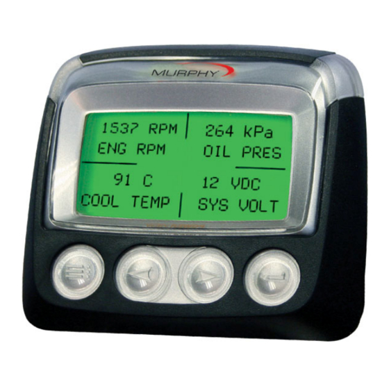
4-Up Display The 4-up display places the parameter data into four areas of the screen known as quadrants. Factory defaults for the 4-up display include coolant temperature, engine speed, oil pressure, and battery voltage. You may customize the 4-up display with parameters you define for each quadrant. 1. -
Page 20
5. Touch Enter and a list of parameters will appear. The parameter that is highlighted is the selected parameter for the screen. The number to the right of the parameter indicates the quadrant in which it is displayed. 1 = upper left quadrant 2 = lower left quadrant 3 = upper right quadrant 4 = lower right quadrant… -
Page 21
8. The parameter in the selected quadrant has changed to the parameter selected in the previous screen. 9. Repeat the parameter selection process until all spaces are filled. 00-02-0795 — 17 — 10-18-11… -
Page 22: Main Menu Options
Main Menu Options This section describes the features listed on the main menu of the PowerView. These menu options are displayed whenever you touch Menu. The Arrow Keys allow you to scroll the items, and Enter selects the highlighted option. Selecting a Language From LANGUAGES, you may select ENGLISH, ESPANOL, FRANCAIS, ITALIANO, or DEUTSCH.
-
Page 23
function, a “No Engine Configuration Data” message displays Service Reminders SERVICE REMINDERS permit you to RESET REMINDERS or MODIFY REMINDERS for changing engine oil, air filters, and hydraulic oil or for servicing the engine and/or machine. NOTE: Service Reminders are internal reminders within PowerView. -
Page 24
4. The Reminder name appears at the top of the screen. The action (ON or OFF) displays mid-screen, and two choices display at screen bottom. Touch Menu to Cancel the action. Touch Enter to choose Reset. 5. If you select Modify Reminders, use the Arrow Keys to highlight the Reminder to modify and touch Enter. -
Page 25
9. A modified Reminder displays a (+) at right of Reminder name when successfully completed. Follow the above steps to modify other Reminders. When finished, touch Menu to return to the Main Menu. Select Units From SELECT UNITS, you may select how information is displayed: ▪… -
Page 26: Utilities Menu
Utilities Menu UTILITIES provide troubleshooting features and displays information about the PowerView configuration. Gage Data View information for optional connected PVA gages. Remove All Gages Reset the gage memory on the PowerView. Software Version This screen lists Configuration, Firmware, Languages, and Bootloader versions for this PowerView unit.
-
Page 27
Modbus Setup 1. From the UTILITIES menu, select MODBUS SETUP. 2. Select either the SLAVE ACTIVE (SCADA or remote Modbus master) or MASTER ACTIVE (auxiliary gages) modes. Touch Enter to toggle between master and slave. 3. Select SERIAL PORT SETUP (slave mode only), then touch Enter. -
Page 28
fault codes. The PowerView always looks for J1939 Version 4 and can be set to read the code as one of three (3) other J1939 versions if Version 4 is not being used. Most engine ECU’s use Version 4, therefore in most cases adjustment of this menu option will not be required. -
Page 29
The default is 20%. NOTE: The PowerView accepts optional Murphy fuel sender (recommend Model ES2F) for fuel level information. A custom setup for a non-Murphy fuel sender is available. For more information, see FUEL SETPOINTS, page 30 (OEM Menu).This parameter provides two setting options. -
Page 30: Oem Menu
OEM Menu The OEM menu is the last item on the Utilities menu. You must have a password to access the OEM menu. Once in the OEM Menu, select an item by highlighting it and touch Enter to reach additional screens. ENTER PASSWORD screen –…
-
Page 31: Canbus Data Rate
and Master Active (which is Auxiliary gages). Highlight your selection and touch Enter. 2) If in Slave Active, select SERIAL PORT SETUP and touch Enter. 3) Scroll through the Serial Port Setup list and make selections for BAUD RATE, PARITY, DATA BITS, and STOP BITS to configure the serial port parameters for your Modbus slave application.
-
Page 32: Set Source Address
1) The message “LISTEN TO ECU: ALL” displays as the default setting. This message indicates the PV101 is listening to all devices on the network. 2) To change the setting to a specific address, touch the Arrow Keys to scroll through the selections (0- 253, and ALL).
-
Page 33: Restore All Defaults
Restore All Defaults PowerView automatically resets after the restore defaults is complete. RESTORING ALL FACTORY DEFAULTS displays when this is selected. Clear Machine Hours Use this to clear machine hours internal to PowerView outside of ECU hours. Set Machine Hours Machine hours calculate internally when the RPM is greater than 50 and the engine is not broadcasting hours.
-
Page 34
¼, ½, and ¾ fuel tank levels. Fuel Setpoints must be ON to work with a non-Murphy fuel sender. Modifying fuel setpoints is a complex process. To assist you in configuring for a Murphy Fuel Sender or programing for a non-Murphy Sender, go to the FW Murphy Web site (www.fwmurphy.com/pv101), locate… -
Page 35: Faults And Warnings
Faults and Warnings The PowerView provides two means for detecting faults and warnings: visual LEDs on the casing (See “Faceplate Features”) and fault indicators on the display. Visual Indication Amber LED (Warning) Red LED (Derate / Shutdown) Fault Indicators 00-02-0795 — 31 — 10-18-11…
-
Page 36
Auxiliary Gage Fault Murphy’s PVA Gages can be attached to the PowerView. If an auxiliary gage should fail, the 1-up or 4-up display will be replaced with the fault message “GAGE NOT RESPONDING”. NOTE: The fault can only be cleared by correcting the cause of the fault condition. -
Page 37
Acknowledging Fault Codes 1. To acknowledge and hide the fault and return to the 1-up or 4-up display, touch Enter. The display will return to the 1-up or 4-up display, but the display will contain the shutdown icon. 2. Touch Enter to redisplay the hidden fault. Touch Enter once again will hide the fault and return the screen to the 1-up or 4-up display. -
Page 38: Troubleshooting
Troubleshooting You may see the following messages displayed. Each gives you specific information about the engine, ECU, or PowerView. WAIT TO START PREHEATING — The ECU is broadcasting a ‘Wait to Start’ message. Engine manufacturers typically recommend against starting the engine while the ECU is broadcasting this message.
-
Page 39
If not, then specifically on the PV101, FUEL LEVEL has been selected for display, and the ANALOG INPUT has been set to FUEL LEVEL, but no Murphy Fuel Sender has been connected to the analog input. 00-02-0795… -
Page 40
The following messages concern information about the PV101. One of the 4-UP quadrants is empty — No parameter has been selected for display in this quadrant. Display is not readable, either very dim or very dark — The LCD contrast may have been over or under adjusted. Press and hold the MENU key for approximately 5 seconds. -
Page 41
NOTES 00-02-0795 — 37 — 10-18-11… -
Page 42
Murphy Industries, Inc., with all rights reserved. © 2011 Murphy Industries, LLC. Other third party product or trade names referenced herein are the property of their respective owners and are used for identification purposes only.
Table of Contents for Murphy PowerView PV-101:
-
(10) The following screen is displayed: NOTE: The numbers displayed on the above screen are examples only. The numbers displayed on the newly set PV101 will be different. NOTE: Once these setpoints are complete, you can add them to your configuration via the Configuration tool and they can become default values.
-
Show Fuel Setpoints The Murphy Standard Fuel Sender settings are preloaded in the device. To view these settings select SHOW FUEL SETPOINTS . The following screen is displayed: NOTE: The numbers displayed on the above screen are Murphy Standard settings. (4)
-
1010585 09-30-10 Section 78 PowerView™ — Model PV101 V2.2 – Fuel Sender Calibration Setting Fuel Level Analog Input Introduction This option enables the operator to configure the PV101 to accept the optional Murphy Fuel Sender (Model ES2F recommended) for fuel level information or to program the unit to accept the non-Murphy fuel sender*. The PV101 is set from the factory to accept a backlight dimmer input. These instructions show exactly what needs to be completed to set the PV101 analog input to
-
The following screen is displayed. Then set the resistive value. It represents the Empty point from the non-Murphy fuel sender that must be sent to the PV101. While sending the resistive value, select [YES] and the PV101 will have a new low fuel setpoint setting. Once the new settings are set, the menu will be displayed. NOTE: Once the setpoint has been set, an asterisk is displayed to the right of the setpoint. Set 1/4 Point, 1/2 Point, and 3/4 Point Add fuel to 25% of the tank’s capacity and select the quarter tan
-
Select ANALOG INPUT Select Fuel Level The next screen displayed is the BACKLIGHT DIMMER/FUEL LEVEL selection screen. Select FUEL LEVEL. (2)
-
Using the Murphy Fuel Sender The next screen displayed is the FUEL SENDER SETUP screen. The PV101 ships from the factory set to be used with a Murphy fuel sender. The FUEL SETPOINTS OFF must be shown to work with a Murphy fuel sender. Press the right and left arrow keys to navigate the menu. There are two pages to this screen. NOTE: When Fuel Setpoints OFF is set, these screens are displayed but they are not available for modification. For a non-Murphy fuel sender, see the USING A NON- MURPHY FUEL SENDER in this document. NOTE: The asterisk i
-
Set Remaining Setpoints Add fuel to 50% of the tank’s capacity to set the 1/2 point setpoint and 75% of the tank’s capacity to set the 3/4 point setpoint. Set Full Point Add fuel to fill the tank to its full capacity and select SET FULL POINT. The following screen is displayed and now the resistive value that represents the Full point from the non-Murphy fuel sender must be sent to the PV101. While sendi
-
Low Fuel Level Setpoint The next screen displayed is the LOW FUEL SETPOINT screen. The default setting is 10%. This setting enables the PV101 to generate a DTC (Diagnostic Trouble Code) displaying low fuel level. Adjusting Low Fuel Level Setting To change the Low Fuel Level setpoint, use the left and right arrows to increase or decrease the set point. Select [MENU] to cancel or [ENTER] to confi
-
Clear Fuel Setpoints Use the right arrow key to scroll down to page 2 and select CLEAR FUEL SETPOINTS . This will clear the Murphy Standard settings. NOTE: The SET EMPTY POINT, SET 1/4 POINT, SET 1/2 POINT, SET 3/4 POINT and SET FULL POINT must be programmed before continuing. Set Empty Point First select SET EMPTY POINT with fuel tank empty. NOTE: The fuel tank m
Questions, Opinions and Exploitation Impressions:
You can ask a question, express your opinion or share our experience of Murphy PowerView PV-101 device using right now.