В этом видео мы вам расскажем о типичной проблеме с топливным насосом на автомобилях JEEP GRAND CHEROKEE WK2 трехлитровый дизель. Сегодня нам привезли на эвакуаторе WK2 2013 года. Машина заводится, но проехать может только несколько метров. Причину неисправности определить было несложно. При включении зажигания нет характерного звука работающего топливного насоса. Проверили питание – на разъем поступает.
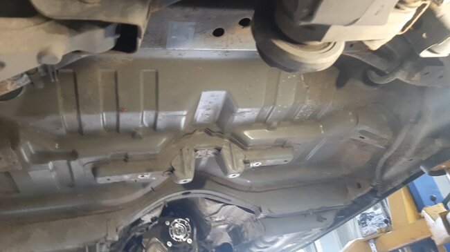
Приняли решение снимать топливный бак – иначе до насоса не добраться. Для этого приходится снимать кардан, глушитель, топливный фильтр и защиты.
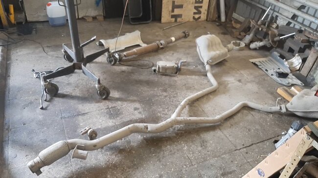
Конструкторы автомобиля не предусмотрели лючок в полу кузова для снятия топливного насоса без снятия бака, как это сделано на многих других автомобилях.
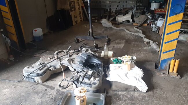
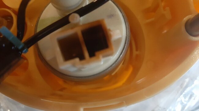
А вот и виновник торжества.
В разъеме проводки и на самом топливном насосе один контакт выгорел полностью. Контакты со временем окисляются, начинают греться, теряют пружинные свойства и начинают подгорать. Корпус разъема тоже обгорел.
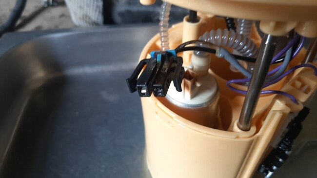
Давайте заглянем внутрь разъема – от контактов просто ничего не осталось.
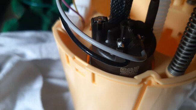
А вот новый насос. Производители, видимо зная об этой проблеме, изменили конструкцию топливного насоса. Теперь разъем между насосом и проводкой отсутствует. Провода напрямую припаяны к насосу. Такая конструкция значительно надежней и безопасней.
Ставим новый топливный насос, и собираем автомобиль.

Расшифровка ошибки P258B у Jeep: Реле давления C или неисправность цепи соленоида
Марка:
Джип
Код:
P258B
Определение:
Реле давления C или неисправность цепи соленоида
Описание:
Компоненты запитаны, а напряжение зажигания больше 9,0 вольт и меньше 18 вольт. Скорость двигателя больше 200 об / мин и меньше 7500 об / мин в течение 5 секунд. Клапан переключения передач C получает команду в положение ВЫКЛ, без хода.
Причина:
Осмотрите проводку на предмет плохих электрических соединений в TCM. Проверьте наличие следующих условий:
- погнутый терминал;
- отключенный терминал;
- поврежденный терминал.
- Плохой терминал натяжение.
- потертый провод.
- обрыв провода внутри дуги.
Бюллетени связанных услуг:
- Просмотреть бюллетень 1
- Просмотреть бюллетень 2
- Просмотреть бюллетень 3
- Просмотреть бюллетень 4
- Просмотреть бюллетень 5
Опрос: Где ремонтируется Ваш автомобиль? (Кол-во голосов: 2085)
У себя в гараже
У официалов
В гараже у Васи
Чтобы проголосовать, кликните на нужный вариант ответа.Результаты
From english:
Decoding the error P258B from Jeep: Pressure Switch C or Solenoid Circuit Malfunction
Make:
Jeep
Code:
P258B
Definition:
Pressure Switch C or Solenoid Circuit Malfunction
Description:
The components are powered and ignition voltage is greater than 9.0 volts and less than 18 volts.Engine speed is greater than 200 RPM and less than 7,500 RPM for 5 seconds.C shift valve is commanded to the OFF,unstroked,position.
Cause:
Inspect the wiring for poor electrical connections at the TCM.Inspect for the following conditions:
- A bent terminal
- A backed-out terminal
- A damaged terminal
- Poor terminal tension
- A chafed wire
- A broken wire inside the insu
Related Service Bulletins:
- View Bulletin 1
- View Bulletin 2
- View Bulletin 3
- View Bulletin 4
- View Bulletin 5
Еще ошибки категории
Ошибки автомобилей разных произвродителей
Опрос: Смогли ли диагностировать неисправность? (Кол-во голосов: 340)
Да, лично
Да, с помощью знакомого
Да, у официального дилера
Нет
Чтобы проголосовать, кликните на нужный вариант ответа.Результаты
Расскажите друзьям:
Поставьте рейтинг, для нас это очень важно:
Голосов: 0 чел. Рейтинг: 0 из 5.
Стандартные коды ошибок OBD2:
Опрос: Помог ли Вам наш сайт? (Кол-во голосов: 439)
Чтобы проголосовать, кликните на нужный вариант ответа.Результаты
Последние комментарии:
Спасибо большое за самый полыный список ошибок!…
Принимая во внимание тот факт, что OBD2 ошибки работы электронных систем автомобиля не всегда на прямую указывают на неработающий элемент, а чаще дают всего лишь общую информацию о неисправности, мы пришли к следующему выводу:
В разных марках и моделях автомобилей одна и также ошибка может возникать как следствие неисправности абсолютно разных элементов.
Стало понятно, что просто необходим ресурс в котором можно найти не только общую информацию об OBD2 ошибке, а практические данные по конкретному автомобилю.
Опыт автоэлектриков показал, что если рассматривать определенную марка-модель автомобиля, то в подавляющем большинстве случаев причина возникновения какой либо ошибки одна и также.
Мы создаем, не без вашей помощи, справочник причинно-следственной связи возникновения той или иной OBD2 ошибки у конкретного автомобиля (марка и модель). Если на Ваш автомобиль не найдено описание (причинно-следственной связи) ошибки, то не стесняйтесь задавайте вопрос.
Если у вас есть опыт в устранении той или иной ошибки — делитесь опытом с другими пользователями. Так мы сможем сформировать полезный ресурс. По капле от каждого и всем будет полезно.
Возможно будет интересно:
Если ошибка указывает на неверные параметры (высокие или низкие значения) какого нибудь из датчиков или анализаторов, то вероятней всего этот элемент исправен, а проблему надо искать так сказать «выше по течению», в элементах работу которых анализирует датчик или зонд.
Если ошибка указывает на постоянно открытый или закрытый клапан, то тут надо подойти к решению вопроса с умом, а не менять бездумно этот элемент. Причин может быть несколько: клапан засорен, клапан заклинил, на клапан приходит неверный сигнал от других неисправных узлов.
Автомобили с каждым днем становятся все более сложными, но и более диагностируемыми. Наш форум создан для всех, от простых автолюбителей до профессиональных автоэлектриков.
P258B Electronic Vacuum Pump Performance — The Electric Vacuum Pump (EVP) system is installed to provide supplemental vacuum to the brake booster, when the engine vacuum supply is low. The pumps is connected to the engine and the brake booster through a series of hoses and one-way flow check valves. A pressure sensor, mounted in the brake booster, provides information to the ABS/ESP Module. This information is then sent to the Powertrain Control Module (PCM) over the CAN C BUS. The PCM modulates the EVP operation to maintain the brake booster vacuum within a given range. This system ensures that the customer experiences a consistent brake pedal feel under all driving conditions.
When monitored with the engine running, the PCM monitors the change in vacuum in the brake booster when the EVP is commanded on over a calibrated threshold of time. Set condition the PCM detects that the chenge in vacuum during the testing period is less than a calibrated threshold. Default action MIL light will illuminate.
Step 1. Check for an active DTC
If DTC P258A is active, perform the diagnostic procedure for P258A before continuing with this test. Diagnose and repair any vacuum pressure sensor DTC that are present in the PCM or ABS Module before continuing with this test procedure. Start the engine and allow it to idle. Press and release the Brake pedal several times to cause the EVP to operate. With the scan tool, read DTC.
Is the DTC active or pending?
Yes, go to step 2.
No, perform the the PCM intermittent condition.
Step 2. Electric Vacuum Pump actuation
Turn the ignition on, engine not running. With the scan tool actuate the Electronic Vacuum Pump.
Does the Electronic Vacuum Pump run?
Yes, go to step 8.
No, go to step 3.
Step 3. Check the Electronic Vacuum Pump output circuit
Disconnect the EVP harness connector. With the scan tool actuate the Electronic Vacuum Pump. Using a 12-volt test light connected to ground, probe the Electric Vacuum Pump output circuit at the Electronic Vacuum Pump harness connector.
Does the test light illuminate brightly?
Yes, go to step 4.
No, go to step 5.
Step 4. Check the EVP ground circuit
Check a 12-volt test light connected to 12-volts, probe the EVP ground circuit at the Electric Vacuum Pump harness connector.
Does the test light illuminate brightly?
Yes, replace the Electric Vacuum Pump.
No, repair the EVP ground circuit for an open.
Step 5. Check the Electric Vacuum Pump output circuit for an open/high resistance
Turn the ignition off, remove the EVP relay from the relay connector. Measure the resistance of the Electric Vacuum Pump output circuit between the EVP relay connector and the EVP harness connector.
Is the resistance below 3.0 Ohms?
Yes, go to step 6.
No, repair the Electric Vacuum Pump output circuit for an open or high resistance.
Step 6. Check the Electric Vacuum Pump output circuit for a short to ground
Check for continuity between ground and the Electric Vacuum Pump output circuit at the EVP relay connector.
Is there continuity between ground and the Electric Vacuum Pump output circuit?
Yes, repair the Electric Vacuum Pump output circuit for a short to ground. If the circuit was shorted to ground, test the fuse in the fuse box and replace as necessary.
No, go to step 7.
Step 7. Check the Fused B+ circuit at the EVP relay
Turn the ignition on, using a 12-volt test light connected to ground, probe the Fused B+ circuit at the EVP relay connector (terminal 30).
Does the test light illuminate brightly?
Yes, replace the Vacuum Pump relay. With the scan tool actuate the Electronic Vacuum Pump. Using a 12-volt test light connected to ground, probe the Electric Vacuum Pump output circuit at the Electric Vacuum Pump harness connector. If the test light still does not illuminate brightly, replace the Front PDC/Fused Box.
No, repair the Fused B+ circuit for an open or short to ground. If no problems are found with the Fused B+ circuit and the fuse is not blown, replace the TIPM or BCM.
Step 8. Check the Vacuum supply line
Turn the ignition off. Check the vacuum supply line to brake booster for a pinched, cut or open hose.
Were any problems found?
Yes, repair as necessary.
No, go to step 9.
Step 9. Vacuum Pressure signal
Start the engine. With the scan tool, view and record the vacuum pressure signal with foot off the brake pedal. With the scan tool, view the vacuum pressure signal while pressing the brake pedal several times. Record the highest value.
Without the brake pedal applied, was the vacuum presure signal -40 kpa (-12 in hg)?
Yes, go to step 10.
No, replace the Brake booster.
Step 10. Check for vacuum pressure signal change
Turn the ignition on, remove the Vacuum Pressure sensor from the Brake booster. Connect a vacuum pump to the vacuum pressure sensor. Apply vacuum to the Vacuum Pressure sensor and watch for signal change.
Is the voltage signal changing on the scan tool as vacuum is being applied?
Yes, go to step 11.
No, replace the Vacuum Pressure Sensor.
Step 11. Check brake booster check valve
Remove the Brake booster check valve. Apply vacuum to the booster side of the check valve.
Is the Brake booster check valve holding vacuum?
Yes, go to step 12.
No, replace the Brake Booster check valve.
Step 12. Check Brake Booster
Reinstall the Brake Booster check valve. Apply vacuum to the brake booster.
Is the Brake booster holding vacuum?
Yes, go to step 13.
No, replace the Brake booster.
Step 13. Check related PCM and component connections
Автор:
Virginia Floyd
Дата создания:
14 Август 2021
Дата обновления:
14 Июнь 2023

Содержание
- Возможные причины
- Возможные симптомы
- P258b Описание
Возможные причины
Возможные симптомы