1. Зафиксируйте код сообщения на фото.
2. Сфотографируйте шильдик пароконвектомата.
3. Оправьте данную информацию, по WhatsApp, (можно использовать форму обратной связи) вашему сервис инженеру вместе с заявкой на диагностику.

Сервис Проверить или заменить
10 Насос парогенератора, контейнер наполнения, шланг насоса
11 Электрод уровня, пропускная способность датчика CDS, плата вхвых.
12 Неисправен датчик CDS
13 Проверить электрод уровня
14 Проверить электрод уровня, измерить электропроводность воды
17 Связаться с RATIONAL, использовать ПО для восстановления
19 Заменить SD-карту
20.x Неисправна термопара, -1 = рабочая камера B1; -2 = коллектор охлаждения B2; -4 = термопара влажности B4; -8 = парогенератор B5; -16: Рабочая камера внизу B9 (напольный аппарат); ; -32: отек для установки B10 (XS)
23 Твердотельные реле по контуру «Пар»
24 Твердотельные реле по контуру «Сухой жар»
25 Нет увеличения нагрузки на мотор при попадании воды на вентилятор: Проверить подачу идавление воды, шланги, датчик CDS, положение навесных рам и рам-тележек с направляющими
26 Только XS: Шаровой клапан не открывается; проверить в функциональном тесте, при необходимости заменить
27 Только XS: Шаровой клапан не закрывается; проверить в функциональном тесте, при необходимости заменить
28.x Термопара: -1: Парогенератор B5 слишком горячий (>170 C); -2: рабочая камера B1 слишком горячая (>350 °C); -4: рабочая камера B1 слишком холодная (<2 °C)
29 Слишком высокая температура платы: проверить воздушный фильтр, вентилятор охлажде-
ния и уплотнение панели управления.
30 Ошибка контроля влажности; проверить датчик дифференциального давления P1
31.x Термопара термокерна В3: -1: Неисправен термокерн рабочей камеры; -2: Аварийный режим термокерна рабочей камеры; -11/12: Термокерн USB 1 неисправен/аварийный режим; -21/22: Термокерн USB 2 неисправен/аварийный режим
32.x Блок зажигания: газовый кран; замените блок зажигания только, если газовые ошибки 33, 36, 39 или 42 возникли более 5-ти раз
33.x Газовая ошибка: проверить газовый кран, газовый клапан или управление от блока зажигания к газовому клапану
34.xx Ошибка сигнала шины: -1 верхний мотор; -2 средний моторе; -4 нижний мотор; -8 плата насоса; -16 подача питания платы вх./вых.; -32 блок зажигания
35 UltraVent: Сигнал шины / внутренняя коммуникация
35.x Ошибка UltraVent: -1 ошибка напряжения; -2 ошибка распознавания фильтра; -3 ошибка контроля термопары; -4 неисправность термопары защиты мотора; -5: Предварительное уведомление (замена фильтра) -6 загрязнение фильтра (немедленная замена); -7 фильтр не установлен/не измеряется дифференциальное давление
36 Ошибка датчика дифференциального давления (нет сигнала 0,5 В; проверить входной сигнал 12 В на P1); P1 должен быть установлен горизонтально
37 Сбой упр. микроклиматом: Проверить подключения шлангов
40 Проверить насос Care (M18) в функциональном тесте (Внимание! одновременно включается Y4 , запустить программу ополаскивания)
41 Функция увлажнения: Проверить клапан Y3, форсунку и трубку впрыска на наличие накипи; CDS не измеряет импульсы; Сбросить ошибку, запустив программу ополаскивания
42.x Не открывается клапан: -1: клапан Y1; -2: Клапан Y2; -3: увлажнение Y3; -4: клапан Care Y4; -5: клапан Klima Y5 / Y15; -6: промывочный клапан Y14
44 Нет нагрева парогенератора или нагрев недостаточен;
46.x SC-насос (M4); -1: неисправен; -2: слишком низкая производительность
47.x Сливной насос M15; -1: неисправен; -2: Слишком низкая производительность
48.x Циркуляционный насос M17; -1: неисправен; -2: Слишком низкая производительность
49.x Насос Care (M18): -1: неисправен; -2: слишком низкая производительность
50 Реальное время (дата и время)
51 Проверить батарейку, при необходимости замените
52 Ошибка светодиодного освещения дверцы: -1 слева; -2 справа
55, 56, 57 Ошибка мотора вентилятора (только в сервисном отчете)
60 Блок зажигания не инициализируется или его работа замедлена — Ошибка в сигнале скорости вращения; выключить и включить аппарат. Изменить тип газа и вернуться к исходному типу газа, при необходимости применить восстановительный файл.
63 Аппарат обнаруживает воду в первый раз после сухой калибровки, после самодиагностики без воды: заново провести калибровку.
70.x -1: Электроотказ вентилятора охлаждения настольного аппарата
-2: Вентилятор охлаждения газового настольного аппарата, электро-/газоотказ напольного аппарата
71.x -1: Сетевая ошибка; -2: Пониженное напряжение блока питания
72 Термостат eSTB для сухого жара или пара: Мигание светодиода на eSTB — ошибка
73.x Ошибка повышенной температуры: -1 верхний мотор; -2 нижний мотор; -4 средний мотор;
-8 плата насоса; -16 блок управления платы вх./вых.; -32 блок зажигания;
75.x 75: Полный отказ интерфейса шины (I2C); -1: Отказ оптимизации энергопотребления; -2: Отказ платы 4-вентильного реле; -3: Отказ платы очистки (XS);
76.x Только США:
-1: ограничено напряжение; -2: ошибка внутренней проверки; -3: неправильная настройка напряжения; -4: слишком большое число каналов; -5: неправильные каналы; -6: неправильное время; -7: ошибка аппаратного обеспечения
110 Ошибка SC-насоса при наличии в парогенераторе раствора Care
120 Нет сигнала электрода уровня при наличии в парогенераторе раствора Care;
130 Необходима ручная очистка от накипи (объем заполнения соответствует 80 % эталонного значения)

Сервис Проверить и при необходимости заменить
2 Оптимизация энергопотребления активна (только со встроенной платой оптимизации энергопотребления)
10 Ошибка автоматики SCНасос парогенератора, контейнер наполнения, шланг насоса
11 Датчик CDS сообщает о слишком большом количестве импульсов
Электрод уровня, пропускная способность датчика CDS, плата вхвых.
12 Датчик CDS не подает сигналовДатчик CDS, плата вхвых., подача воды
14 Электрод уровня не обнаруживает воду несмотря на обнаружение импульсов датчиком CDS Электрод уровня воды, электропроводимость воды
16 Структура ЭСППЗУ была создана более новым по сравнению с установленным программным обеспечением, обновите аппарат до актуальной версии программного обеспечения
17.X Ошибка данных аппарата (суб-ошибка только для внутренних целей)
Связаться с RATIONAL, использовать ПО для восстановления
19.X x= тип ошибки; -1= ЭСППЗУ отсутствует или не распознано;
-2 = ошибка внутренней памяти (возможно, извлечен аккумулятор)
20.X Неисправна термопара, x= термопара; -1 = рабочая камера B1; -2 = коллектор охлаждения
B2; -4 = термопара влажности B4; -8 = парогенератор B5; -9 = неисправна термопара B9 —только напольные аппараты
23 Повышение температуры в парогенераторе без запроса Проверка нагрева парогенератора
24 Повышение температуры в рабочей камере без запроса
Проверка парогенератора Сервис Проверить и при необходимости заменить
25 Не обнаруживается вода во время очистки
Не работают вентиляторы/нет увеличения нагрузки на мотор при попадании воды на вентилятор. Проверить подачу и давление воды, шланги, датчик CDS, положение рам и теле жек с направляющими
28.x Термопара, x= ошибка: -1: Парогенератор B5 слишком горячий (>170 C); -2: рабочая камера B1 слишком горячая (>350 °C); -4: парогенератор B5 слишком холодный (<2 °C, возмо жен нагрев до 4 °C)
29 Слишком высокая температура платы (платы вх./вых., насосов, ЦП): воздушный фильтр,вентилятор охлаждения
30 Некорректное функционирование измерения влажности
Датчик давления P1, подключения шлангов, измерительные патрубки, датчик влажности B4
31.xx Термопара В3 термокерна, x = ошибка: -1: дефект термокерна; -11: дефект внешнего термокерна
32.x Блок зажигания, x= ошибка
-1: 5 сбоев зажигания (проверить подачу газа)
-2: Обнаружение тока пламени без требования нагрева
-3: Горелка 5 раз выключается при требовании нагрева
33.x Ошибка газовой горелки, x= ошибка
-1: внутренняя ошибка блока зажигания (выключите и снова включите аппарат)
-2: Ошибка инициализации блока поджига (смените тип газа и вернитесь к исходному типу газа)
-3: Частота тока в сети за пределами допустимого диапазона
-4: Фаза/нейтраль перепутаны (переверните сетевой штекер или поправьте кабель)
-5: Внутренний дефект блока зажигания, замените блок зажигания
34.xx Ошибка сигнала шины: -1 верхний мотор; -2 средний мотор; -4 нижний мотор (только для напольных аппаратов); -8 плата насоса; -16 подача питания платы вх./вых.; -32 блок зажигания;
35 UltraVent: Сигнал шины / внутренняя коммуникация
35.x Ошибка UltraVent: -1 ошибка напряжения; -2 ошибка распознавания фильтра (только для UV Plus); -3 ошибка контроля термопары; -4 неисправность термопары защиты мотора; -5/6 загрязнение фильтра (предварительное уведомление/немедленная замена); -7 фильтр не установлен/не измеряется дифференциальное давление
36 Ошибка датчика дифференциального давления (нет сигнала 0,5 ; проверьте 12 В на P1); P1 должен быть установлен горизонтально
37 Сбой упр. микроклиматом: Проверить подключения шлангов
40 Проверьте насос Care (M18) в функциональном тесте (Внимание: одновременно включается Y4, запустите программу ополаскивания)
42.x Не открывается клапан: -1: Заполните Y1; -2: Управление Y2; -4 Care Y4; -5 климат Y5 / Y15
43.x Не закрывается клапан: -1: клапан Y1; -2: клапан Y2; -3: клапан Y3; -4: клапан Care Y4; -5: клапан ClimaY5 / Y15; -6: клапан CleanJet Y14
44 Во вемя очистки нет нагрева парогенератора или нагрев недостаточен;
46.x Насос парогенератора M4; x = тип ошибки: Слишком низкая производительность
47 Сливной насос (M15); -1: дефект; -2: Слишком низкая производительность
48 Циркуляционный насос (M17); -1: дефект; -2: Слишком низкая производительность
49 Насос Care (M18) ; x= тип ошибки: -1: дефект; -2: Слишком низкая производительность
50 Реальное время (дата и время) не запущено
51 Проверить батарейку, при необходимости замените
52 Ошибка светодиодного освещения рабочей камеры
63 Обнаружена вода после сухой калибровки, выполнить самотестирование с водой.
70 Ошибка охл. вент.
71.x Ошибка питания -1: Общая ошибка; -2: Пониженное напряжение (<170 В)
72 Термостат eSTB рабочей камеры или парогенератора: Мигание светодиода на eSTB — ошибка, см. описание ниже
73.x Ошибка повышенной температуры: -1 верхний мотор; -2 нижний мотор; -4 средний мотор; -8 плата насоса; -32 блок управления; -32 блок зажигания платы вх./вых.
75.x Внутренний интерфейс шины: -1 Не распознана оптимизация энергопотребления дополнительной платы; -2: 4-канальное реле дополнительной платы не обнаружено, -4 (только США) плата переключения напряжения не обнаружена
76.xx Аппарата только в США
Ошибка платы переключения напряжения -1: Напряжение слишком низкое; -2: Ошибка внутренней перепроверки; -3 неправильная настройка напряжения от 4 до -7: внутренние
ошибки
90 Аппарат еще не откалиброван, выполните калибровку
110 Ошибка насос парогенератора при наличии в парогенераторе раствора Care
(Устраните ошибку и разъедините в Основных настройках «Очистка разблокировки»)
120 Электрод уровня без сигнала при наличии в парогенераторе химикатов Care;
(Устраните ошибку и разъедините в Основных настройках «Очистка разблокировки»)
121 Дополнительная функция при работе аппарата без воды: Примечание о заполнении водой коллектора охлаждения
200 Сбой автоматического позиционирования мотора (в дальнейшем в основном ошибка 201)
201 Выполнить распределение мотора
900.x -48: Батарейка извлечена, ошибка данных устройства и инициализации времени
1000 Нехватка воды, проверьте подачу воды
1016 USB-накопитель уже присутствует
1017 Неисправность USB-накопителя
1022 отсутствует вода во время процедуры включения (измерение CDS)
1025 Сбой загрузки и выгрузки программы из-за ошибки ЭСППЗУ
1026 Загрузка программы невозможна из-за ошибки создания программы
1033.x Система здорова: -1: несовместимое ПО плата вхвых; -2: неизвестная версия ПО платы вхвых; -3: Проверить систему шины
От ПО версии 5.0.X: Нажатие кнопки 1 (см. предыдущую страницу) отображается соответствующий узел шины.
2000.x Ошибка обновления ПО: -1: Превышено время ожидания; -2-3: макс. время обновления превышено; -4: Устройство в режиме диагностики или самодиагностики; -5: Попытка обновления во время готовки; -6: Попытка обновления при отключении питания; -7: Попытка обновления в демо-режиме
Начиная с версии ПО 5.0.X отменяются коды ошибок
Сервис Проверить и при необходимости заменить
1001 Перезапуск горелки, проверить подачу газа
1002 Проверить подключение к сети и полярность
1003 Нехватка воды >15 минут
1010 Проверить воздушный фильтр
1011 Проверить батарейку
1012 Выполнить калибровку
1018 Ошибка вытяжного зонта
1020 Неисправность мотора
1021.x Неисправность модуля оптимизации энергопотребления: -1-2: 4-канальное реле неисправно; 3: Неправильное напряжение США
1024 Прерывание из-за неисправного термокерна


E10
Where
does it display? Timer
What’s
the cause? External EEPROM
Why? Defective
NOTE: PLEASE SUBSCRIBE E-MAIL AND YOUTUBE CHANNEL
E11
Where
does it display? Timer
What’s
the cause? Mode switch
Why? Cooking mode couldn’t be identified five seconds after the unit
was switched on
E12 / 1 St
Where
does E12 display? Timer
Where
does 1 St alternate display? Internal Cabinet
Display
What’s
the cause? Bottom fan motor issue,make sure 3 phase getting in to the machine
Why? Motor is defective (St=Status)
E12 / 1 Co
Where
does E12 display? Timer
Where
does 1 Co display? Internal Cabinet Display
What’s
the cause? Bottom fan motor issue,make sure 3 phase getting in to the machine
Why? Bus failure (Co=Communication)
E12 / 2 St
Where
does E12 display? Timer
Where
does 2 St alternate display? Internal Cabinet
Display
What’s
the cause? Top fan motor issue,make sure 3 phase getting in to the machine
Why? Motor is defective (St=Status)
E12 / 2 Co
Where
does E12 display? Timer
Where
does 2 Co alternate display? Internal Cabinet
Display
What’s
the cause? Top fan motor issue,make sure 3 phase getting in to the machine
Why? Bus failure (Co=Communication)
E13
Where
does it display? Timer
What’s
the cause? M4 SC pump
Why? Malfunction,need to changing or some time pump area getting scaling and blocked
E14
Where
does it display? Timer
What’s
the cause? Solenoid valve filling Y1
Why? Malfunction
E15
Where
does it display? Timer
What’s
the cause??PCB temperature
Why? Above 185?F (85?C)
E16
Where
does it display? Timer
What’s
the cause??Steam generator
Why? B5 temperature above 356?F (180?C)
E17
Where
does it display? Timer
What’s
the cause??Steam generator
Why? B5 temperature below 23?F (-5?C)
E18
Where
does it display? Timer
What’s
the cause??Interior cabinet temperature
Why? B1 temperature above 644?F (340?C)
E20 / 1
Where
does E20 display? Timer
Where
does 1_ alternate display? Internal Cabinet Display
What’s
the cause??Ignition box 1
Why??Ignition box isn’t replying due to bus failure
E21 / 2
Where
does E21 display? Timer
Where
does 2_ alternate display? Internal Cabinet Display
What’s
the cause??Ignition box 2
Why??Ignition box isn’t replying due to bus failure
E21 / 1
Where
does E21 display? Timer
Where
does 1xx display? Internal Cabinet Display
What’s
the cause??Ignition box 1 steam
Why??Defective ignition box
E22 / 2
Where
does E22 display? Timer
Where
does 2xx alternate display? Internal Cabinet Display
What’s
the cause??Ignition box 1 hot air
Why??Defective ignition box
E22 / 3
Where
does E22 display? Timer
Where
does 3xx alternate display? Internal Cabinet Display
What’s
the cause??Ignition box 2 hot air
Why??Defective ignition box
E22 / 1
Where
does E22 display? Timer
Where
does 1xx alternate display? Internal Cabinet Display
What’s
the cause??Ignition box 1 steam
Why??Testing and monitoring ignition is required
E23 / 2
Where
does E23 display? Timer
Where
does 2xx alternate display? Internal Cabinet Display
What’s
the cause??Ignition box 1 hot air
Why??Testing and monitoring ignition is required
E23 / 3
Where
does E23 display? Timer
Where
does 3xx alternate display? Internal Cabinet Display
What’s
the cause??Ignition box 2 hot air
Why??Testing and monitoring ignition is required
E24
Where
does E24 display? Timer
What’s
the cause? EEPROM
Why??EEPROM’s data structure doesn’t match with software
Contributions
from the Community
Our
community members have posted about service codes associated with other
Rational SCC models or software versions. These are some of the most helpful
from over the years.
On models produced up to October 2011 (index E
& G), Service 21 meant only that the cam on clima motor did not do a?360
degree rotation in the?allowed 20 seconds.? Possible it did not rotate at
all.
Every time the door is opened and closed while
the unit is on, it does a check (initialization of the Clima Valve and times
it).
While
we addressed this code above,PLEASE SEND MAIL provided more details on it:
33-1 means bottom ignition module.? But this only
applies on floor models such as 201 & 202.? In this case of a 102 (table
model) there is only one ignition module so the -1 has no need.? But it shows
anyway.
Требуется руководство для вашей Rational CombiMaster Plus духовой шкаф? Ниже вы можете просмотреть и загрузить бесплатно руководство в формате PDF. Кроме того, приведены часто задаваемые вопросы, рейтинг изделия и отзывы пользователей, что позволит оптимально использовать ваше изделие. Если это не то руководство, которое вы искали, – свяжитесь с нами.
Ваше устройство неисправно, и в руководстве отсутствует решение? Перейдите в Repair Café для получения бесплатных ремонтных услуг.
Руководство

Рейтинг
Сообщите нам, что вы думаете о Rational CombiMaster Plus духовой шкаф, оставив оценку продукта. Хотите поделиться вашими впечатлениями от данного изделия или задать вопрос? Вы можете оставить комментарий в нижней части страницы.
Довольны ли вы данным изделием Rational?
Да Нет
Будьте первым, кто оценит это изделие
0 голоса
Часто задаваемые вопросы
Наша служба поддержки выполняет поиск полезной информации по изделиям и отвечает на часто задаваемые вопросы. Если вы заметили неточность в наших часто задаваемых вопросах, сообщите нам об этом с помощью нашей контактной формы.
Духовка недостаточно нагревается. Что мне делать? Проверенный
За нагревание духовки до заданной температуры отвечает термостат. Скорее всего, термостат неисправен. Его следует заменить. В случае сомнений обратитесь к производителю.
Это было полезно (2201)
Что такое пиролиз? Проверенный
Некоторые духовки оснащены функцией пиролиза. Это система очистки, которая сжигает грязь и жир в духовке за счет очень высоких температур. После пиролиза вся грязь превратится в золу, и ее легко удалить. Если духовка имеет функцию пиролиза, рекомендуется использовать ее 3-4 раза в год, чтобы духовка оставалась чистой.
Это было полезно (2025)
Почему в духовке при разогреве накапливается дым? Проверенный
Вероятно, в духовке остались остатки пищи от предыдущего использования. При нагревании особенно жирные остатки пищи могут выделять дым. Тщательно очистите духовку.
Это было полезно (486)
Когда я использую духовку, продукты часто падают на дно, вызывая дым. Как я могу предотвратить это? Проверенный
Многие духовки поставляются с решеткой и противнем. Когда пища готовится на решетке, противень можно ставить на дно, чтобы остатки пищи не пригорали и не задымились.
Это было полезно (486)
Могу ли я приготовить несколько блюд одновременно, используя несколько противней для гриля? Проверенный
Технически это возможно. Однако это зависит от типа продуктов, нужно ли вам регулировать время приготовления или менять противни на полпути во время приготовления.
Это было полезно (485)
does it display? Timer
the cause? External EEPROM
does it display? Timer
the cause? Mode switch
was switched on
does E12 display? Timer
does 1 St alternate display? Internal Cabinet
Display
the cause? Bottom fan motor issue,make sure 3 phase getting in to the machine
does E12 display? Timer
does 1 Co display? Internal Cabinet Display
the cause? Bottom fan motor issue,make sure 3 phase getting in to the machine
does E12 display? Timer
does 2 St alternate display? Internal Cabinet
Display
the cause? Top fan motor issue,make sure 3 phase getting in to the machine
does E12 display? Timer
does 2 Co alternate display? Internal Cabinet
Display
the cause? Top fan motor issue,make sure 3 phase getting in to the machine
does it display? Timer
the cause? M4 SC pump
does it display? Timer
the cause? Solenoid valve filling Y1
does it display? Timer
the cause??PCB temperature
does it display? Timer
the cause??Steam generator
does it display? Timer
the cause??Steam generator
does it display? Timer
the cause??Interior cabinet temperature
does E20 display? Timer
does 1_ alternate display? Internal Cabinet Display
the cause??Ignition box 1
does E21 display? Timer
does 2_ alternate display? Internal Cabinet Display
the cause??Ignition box 2
does E21 display? Timer
does 1xx display? Internal Cabinet Display
the cause??Ignition box 1 steam
does E22 display? Timer
does 2xx alternate display? Internal Cabinet Display
the cause??Ignition box 1 hot air
does E22 display? Timer
does 3xx alternate display? Internal Cabinet Display
the cause??Ignition box 2 hot air
does E22 display? Timer
does 1xx alternate display? Internal Cabinet Display
the cause??Ignition box 1 steam
does E23 display? Timer
does 2xx alternate display? Internal Cabinet Display
the cause??Ignition box 1 hot air
does E23 display? Timer
does 3xx alternate display? Internal Cabinet Display
the cause??Ignition box 2 hot air
does E24 display? Timer
the cause? EEPROM
from the Community
community members have posted about service codes associated with other
Rational SCC models or software versions. These are some of the most helpful
from over the years.
& G), Service 21 meant only that the cam on clima motor did not do a?360
degree rotation in the?allowed 20 seconds.? Possible it did not rotate at
all.
the unit is on, it does a check (initialization of the Clima Valve and times
it).
we addressed this code above,PLEASE SEND MAIL provided more details on it:
applies on floor models such as 201 & 202.? In this case of a 102 (table
model) there is only one ignition module so the -1 has no need.? But it shows
anyway.
1. Зафиксируйте код сообщения на фото.
2. Сфотографируйте шильдик пароконвектомата.
3. Оправьте данную информацию, по WhatsApp, (можно использовать форму обратной связи) вашему сервис инженеру вместе с заявкой на диагностику.
Сервис Проверить или заменить
10 Насос парогенератора, контейнер наполнения, шланг насоса
11 Электрод уровня, пропускная способность датчика CDS, плата вхвых.
12 Неисправен датчик CDS
13 Проверить электрод уровня
14 Проверить электрод уровня, измерить электропроводность воды
17 Связаться с RATIONAL, использовать ПО для восстановления
19 Заменить SD-карту
20.x Неисправна термопара, -1 = рабочая камера B1; -2 = коллектор охлаждения B2; -4 = термопара влажности B4; -8 = парогенератор B5; -16: Рабочая камера внизу B9 (напольный аппарат); ; -32: отек для установки B10 (XS)
23 Твердотельные реле по контуру «Пар»
24 Твердотельные реле по контуру «Сухой жар»
25 Нет увеличения нагрузки на мотор при попадании воды на вентилятор: Проверить подачу идавление воды, шланги, датчик CDS, положение навесных рам и рам-тележек с направляющими
26 Только XS: Шаровой клапан не открывается; проверить в функциональном тесте, при необходимости заменить
27 Только XS: Шаровой клапан не закрывается; проверить в функциональном тесте, при необходимости заменить
28.x Термопара: -1: Парогенератор B5 слишком горячий (>170 C); -2: рабочая камера B1 слишком горячая (>350 °C); -4: рабочая камера B1 слишком холодная (<2 °C)
29 Слишком высокая температура платы: проверить воздушный фильтр, вентилятор охлажде-
ния и уплотнение панели управления.
30 Ошибка контроля влажности; проверить датчик дифференциального давления P1
31.x Термопара термокерна В3: -1: Неисправен термокерн рабочей камеры; -2: Аварийный режим термокерна рабочей камеры; -11/12: Термокерн USB 1 неисправен/аварийный режим; -21/22: Термокерн USB 2 неисправен/аварийный режим
32.x Блок зажигания: газовый кран; замените блок зажигания только, если газовые ошибки 33, 36, 39 или 42 возникли более 5-ти раз
33.x Газовая ошибка: проверить газовый кран, газовый клапан или управление от блока зажигания к газовому клапану
34.xx Ошибка сигнала шины: -1 верхний мотор; -2 средний моторе; -4 нижний мотор; -8 плата насоса; -16 подача питания платы вх./вых.; -32 блок зажигания
35 UltraVent: Сигнал шины / внутренняя коммуникация
35.x Ошибка UltraVent: -1 ошибка напряжения; -2 ошибка распознавания фильтра; -3 ошибка контроля термопары; -4 неисправность термопары защиты мотора; -5: Предварительное уведомление (замена фильтра) -6 загрязнение фильтра (немедленная замена); -7 фильтр не установлен/не измеряется дифференциальное давление
36 Ошибка датчика дифференциального давления (нет сигнала 0,5 В; проверить входной сигнал 12 В на P1); P1 должен быть установлен горизонтально
37 Сбой упр. микроклиматом: Проверить подключения шлангов
40 Проверить насос Care (M18) в функциональном тесте (Внимание! одновременно включается Y4 , запустить программу ополаскивания)
41 Функция увлажнения: Проверить клапан Y3, форсунку и трубку впрыска на наличие накипи; CDS не измеряет импульсы; Сбросить ошибку, запустив программу ополаскивания
42.x Не открывается клапан: -1: клапан Y1; -2: Клапан Y2; -3: увлажнение Y3; -4: клапан Care Y4; -5: клапан Klima Y5 / Y15; -6: промывочный клапан Y14
44 Нет нагрева парогенератора или нагрев недостаточен;
46.x SC-насос (M4); -1: неисправен; -2: слишком низкая производительность
47.x Сливной насос M15; -1: неисправен; -2: Слишком низкая производительность
48.x Циркуляционный насос M17; -1: неисправен; -2: Слишком низкая производительность
49.x Насос Care (M18): -1: неисправен; -2: слишком низкая производительность
50 Реальное время (дата и время)
51 Проверить батарейку, при необходимости замените
52 Ошибка светодиодного освещения дверцы: -1 слева; -2 справа
55, 56, 57 Ошибка мотора вентилятора (только в сервисном отчете)
60 Блок зажигания не инициализируется или его работа замедлена — Ошибка в сигнале скорости вращения; выключить и включить аппарат. Изменить тип газа и вернуться к исходному типу газа, при необходимости применить восстановительный файл.
63 Аппарат обнаруживает воду в первый раз после сухой калибровки, после самодиагностики без воды: заново провести калибровку.
70.x -1: Электроотказ вентилятора охлаждения настольного аппарата
-2: Вентилятор охлаждения газового настольного аппарата, электро-/газоотказ напольного аппарата
71.x -1: Сетевая ошибка; -2: Пониженное напряжение блока питания
72 Термостат eSTB для сухого жара или пара: Мигание светодиода на eSTB — ошибка
73.x Ошибка повышенной температуры: -1 верхний мотор; -2 нижний мотор; -4 средний мотор;
-8 плата насоса; -16 блок управления платы вх./вых.; -32 блок зажигания;
75.x 75: Полный отказ интерфейса шины (I2C); -1: Отказ оптимизации энергопотребления; -2: Отказ платы 4-вентильного реле; -3: Отказ платы очистки (XS);
76.x Только США:
-1: ограничено напряжение; -2: ошибка внутренней проверки; -3: неправильная настройка напряжения; -4: слишком большое число каналов; -5: неправильные каналы; -6: неправильное время; -7: ошибка аппаратного обеспечения
110 Ошибка SC-насоса при наличии в парогенераторе раствора Care
120 Нет сигнала электрода уровня при наличии в парогенераторе раствора Care;
130 Необходима ручная очистка от накипи (объем заполнения соответствует 80 % эталонного значения)
Сервис Проверить и при необходимости заменить
2 Оптимизация энергопотребления активна (только со встроенной платой оптимизации энергопотребления)
10 Ошибка автоматики SCНасос парогенератора, контейнер наполнения, шланг насоса
11 Датчик CDS сообщает о слишком большом количестве импульсов
Электрод уровня, пропускная способность датчика CDS, плата вхвых.
12 Датчик CDS не подает сигналовДатчик CDS, плата вхвых., подача воды
14 Электрод уровня не обнаруживает воду несмотря на обнаружение импульсов датчиком CDS Электрод уровня воды, электропроводимость воды
16 Структура ЭСППЗУ была создана более новым по сравнению с установленным программным обеспечением, обновите аппарат до актуальной версии программного обеспечения
17.X Ошибка данных аппарата (суб-ошибка только для внутренних целей)
Связаться с RATIONAL, использовать ПО для восстановления
19.X x= тип ошибки; -1= ЭСППЗУ отсутствует или не распознано;
-2 = ошибка внутренней памяти (возможно, извлечен аккумулятор)
20.X Неисправна термопара, x= термопара; -1 = рабочая камера B1; -2 = коллектор охлаждения
B2; -4 = термопара влажности B4; -8 = парогенератор B5; -9 = неисправна термопара B9 —только напольные аппараты
23 Повышение температуры в парогенераторе без запроса Проверка нагрева парогенератора
24 Повышение температуры в рабочей камере без запроса
Проверка парогенератора Сервис Проверить и при необходимости заменить
25 Не обнаруживается вода во время очистки
Не работают вентиляторы/нет увеличения нагрузки на мотор при попадании воды на вентилятор. Проверить подачу и давление воды, шланги, датчик CDS, положение рам и теле жек с направляющими
28.x Термопара, x= ошибка: -1: Парогенератор B5 слишком горячий (>170 C); -2: рабочая камера B1 слишком горячая (>350 °C); -4: парогенератор B5 слишком холодный (<2 °C, возмо жен нагрев до 4 °C)
29 Слишком высокая температура платы (платы вх./вых., насосов, ЦП): воздушный фильтр,вентилятор охлаждения
30 Некорректное функционирование измерения влажности
Датчик давления P1, подключения шлангов, измерительные патрубки, датчик влажности B4
31.xx Термопара В3 термокерна, x = ошибка: -1: дефект термокерна; -11: дефект внешнего термокерна
32.x Блок зажигания, x= ошибка
-1: 5 сбоев зажигания (проверить подачу газа)
-2: Обнаружение тока пламени без требования нагрева
-3: Горелка 5 раз выключается при требовании нагрева
33.x Ошибка газовой горелки, x= ошибка
-1: внутренняя ошибка блока зажигания (выключите и снова включите аппарат)
-2: Ошибка инициализации блока поджига (смените тип газа и вернитесь к исходному типу газа)
-3: Частота тока в сети за пределами допустимого диапазона
-4: Фаза/нейтраль перепутаны (переверните сетевой штекер или поправьте кабель)
-5: Внутренний дефект блока зажигания, замените блок зажигания
34.xx Ошибка сигнала шины: -1 верхний мотор; -2 средний мотор; -4 нижний мотор (только для напольных аппаратов); -8 плата насоса; -16 подача питания платы вх./вых.; -32 блок зажигания;
35 UltraVent: Сигнал шины / внутренняя коммуникация
35.x Ошибка UltraVent: -1 ошибка напряжения; -2 ошибка распознавания фильтра (только для UV Plus); -3 ошибка контроля термопары; -4 неисправность термопары защиты мотора; -5/6 загрязнение фильтра (предварительное уведомление/немедленная замена); -7 фильтр не установлен/не измеряется дифференциальное давление
36 Ошибка датчика дифференциального давления (нет сигнала 0,5 ; проверьте 12 В на P1); P1 должен быть установлен горизонтально
37 Сбой упр. микроклиматом: Проверить подключения шлангов
40 Проверьте насос Care (M18) в функциональном тесте (Внимание: одновременно включается Y4, запустите программу ополаскивания)
42.x Не открывается клапан: -1: Заполните Y1; -2: Управление Y2; -4 Care Y4; -5 климат Y5 / Y15
43.x Не закрывается клапан: -1: клапан Y1; -2: клапан Y2; -3: клапан Y3; -4: клапан Care Y4; -5: клапан ClimaY5 / Y15; -6: клапан CleanJet Y14
44 Во вемя очистки нет нагрева парогенератора или нагрев недостаточен;
46.x Насос парогенератора M4; x = тип ошибки: Слишком низкая производительность
47 Сливной насос (M15); -1: дефект; -2: Слишком низкая производительность
48 Циркуляционный насос (M17); -1: дефект; -2: Слишком низкая производительность
49 Насос Care (M18) ; x= тип ошибки: -1: дефект; -2: Слишком низкая производительность
50 Реальное время (дата и время) не запущено
51 Проверить батарейку, при необходимости замените
52 Ошибка светодиодного освещения рабочей камеры
63 Обнаружена вода после сухой калибровки, выполнить самотестирование с водой.
70 Ошибка охл. вент.
71.x Ошибка питания -1: Общая ошибка; -2: Пониженное напряжение (<170 В)
72 Термостат eSTB рабочей камеры или парогенератора: Мигание светодиода на eSTB — ошибка, см. описание ниже
73.x Ошибка повышенной температуры: -1 верхний мотор; -2 нижний мотор; -4 средний мотор; -8 плата насоса; -32 блок управления; -32 блок зажигания платы вх./вых.
75.x Внутренний интерфейс шины: -1 Не распознана оптимизация энергопотребления дополнительной платы; -2: 4-канальное реле дополнительной платы не обнаружено, -4 (только США) плата переключения напряжения не обнаружена
76.xx Аппарата только в США
Ошибка платы переключения напряжения -1: Напряжение слишком низкое; -2: Ошибка внутренней перепроверки; -3 неправильная настройка напряжения от 4 до -7: внутренние
ошибки
90 Аппарат еще не откалиброван, выполните калибровку
110 Ошибка насос парогенератора при наличии в парогенераторе раствора Care
(Устраните ошибку и разъедините в Основных настройках «Очистка разблокировки»)
120 Электрод уровня без сигнала при наличии в парогенераторе химикатов Care;
(Устраните ошибку и разъедините в Основных настройках «Очистка разблокировки»)
121 Дополнительная функция при работе аппарата без воды: Примечание о заполнении водой коллектора охлаждения
200 Сбой автоматического позиционирования мотора (в дальнейшем в основном ошибка 201)
201 Выполнить распределение мотора
900.x -48: Батарейка извлечена, ошибка данных устройства и инициализации времени
1000 Нехватка воды, проверьте подачу воды
1016 USB-накопитель уже присутствует
1017 Неисправность USB-накопителя
1022 отсутствует вода во время процедуры включения (измерение CDS)
1025 Сбой загрузки и выгрузки программы из-за ошибки ЭСППЗУ
1026 Загрузка программы невозможна из-за ошибки создания программы
1033.x Система здорова: -1: несовместимое ПО плата вхвых; -2: неизвестная версия ПО платы вхвых; -3: Проверить систему шины
От ПО версии 5.0.X: Нажатие кнопки 1 (см. предыдущую страницу) отображается соответствующий узел шины.
2000.x Ошибка обновления ПО: -1: Превышено время ожидания; -2-3: макс. время обновления превышено; -4: Устройство в режиме диагностики или самодиагностики; -5: Попытка обновления во время готовки; -6: Попытка обновления при отключении питания; -7: Попытка обновления в демо-режиме
Начиная с версии ПО 5.0.X отменяются коды ошибок
Сервис Проверить и при необходимости заменить
1001 Перезапуск горелки, проверить подачу газа
1002 Проверить подключение к сети и полярность
1003 Нехватка воды >15 минут
1010 Проверить воздушный фильтр
1011 Проверить батарейку
1012 Выполнить калибровку
1018 Ошибка вытяжного зонта
1020 Неисправность мотора
1021.x Неисправность модуля оптимизации энергопотребления: -1-2: 4-канальное реле неисправно; 3: Неправильное напряжение США
1024 Прерывание из-за неисправного термокерна
 Loading…
![]()
Training Manual
Basics, Maintenance and Accessories
SelfCookingCenter® whitefficiency® (SCC_WE)
CombiMaster Plus (CM_P)
Voltage
Software
Installation
Water quality
Accessories
Air supply Gas
Original components
Flue venting
Type of gas
Drain
V02 en, Basic_Maintenance_Accessories

General hints:
Isolate the appliance from mains supply before opening the appliance
When working with chemicals, i.e. aggressive cleaning materials always wear protective clothing, goggles and gloves!
After maintenance / repair the appliance must be checked for electrical safety in accordance with your national, state and local requirements!
Whenever working on any gas component like:
Gas valve, gas blower and / or changing connected type of gas a detailed flue gas analysis MUST be done using adequate CO and CO2 measuring equipment! This shall ONLY be done by trained technicians! Always check appliance for possible gas leakages!
© 2011 Rational Technical Services. All rights reserved.
Please note that any technical information concerning Rational products must NOT be forwarded to any third party.
|
V02 en, Basic_Maintenance_Accessories |
— 2 — |

List of content
Basic topics
|
Company history |
4 |
||
|
History of the Combi Steamer |
5 |
||
|
Structure of serial number |
6 |
||
|
Unit history: Control panel Layout |
7 |
||
|
Unit sizes |
8 |
||
|
Basic principle |
9 |
||
|
General information about water |
10 |
||
|
Installation — Duties and responsibilities |
12 |
||
|
Relationship: Installation — Components — Environment |
13 |
||
|
Check list |
|||
|
Preinstallation checklist |
14 |
||
|
Installation sheet — Electric / Gas units — Electrical connection |
18 |
||
|
Installation sheet — Electric / Gas units — Water connection |
19 |
||
|
Installation sheet — Electric / Gas units — Drain connection |
20 |
||
|
Installation sheet — Gas units — Gas connection |
21 |
||
|
Commissioning — Preventive maintenance |
|||
|
Installation/Commissioning Checklist |
22 |
||
|
Preventive maintenance |
27 |
||
|
Descaling — Cleaning |
|||
|
Instruction for manual descaling |
30 |
||
|
Additional information for manual descaling |
33 |
||
|
User instruction electrical descaler pump |
34 |
||
|
Daily care — Unit and Door Gasket |
36 |
||
|
Instruction for manual cleaning |
37 |
||
|
Accessories |
|||
|
Ultravent (UV) |
38 |
||
|
CombiDuo, Thermo cabinet |
41 |
||
|
Condensation breaker steam |
42 |
||
|
Draft Diverter Gas units |
42 |
||
|
Sicotronic |
43 |
||
|
Ethernet Connection |
43 |
||
|
Reporting forms |
|||
|
Product surveillance guideline |
44 |
||
|
Registration form product surveillance |
45 |
||
|
Registration form „dead on arrival“ |
46 |
|
— 3 — |
V02 en, Basic_Maintenance_Accessories |

Company history
Milestone of an extraordinary company history
1973 Foundation of RATIONAL GmbH as a company for producing and selling of hot air ovens in
Germany
1976 Invention of the RATIONAL Combi-Steamer
1993 Opening of plant number 2
1993 Invention of the RATIONAL Clima Combi®
1997 Invention of the RATIONAL ClimaPlus Combi®
2000 Going public RATIONAL AG
2000 CleanJet® – World wide the first full automatic self clean system
2004 Invention of the first SelfCooking Center® of the world
2005 Invention of the first VarioCooking Center® of the world by our daughter company FRIMA. Cooking, roasting, frying, simply better, in one appliance, with double speed.
2008 Opening of the third and biggest plant in Landsberg
2008 CleanJet+Care® – cleaning intelligence for a maximum reliability
2011 Invention of SelfCooking Center whitefficiency with Efficient Level Control
The following subsidiaries were founded:
UK, France, Japan, USA, Italy, Scandinavia, Switzerland, Canada, Spain,
Germany, Russia, Austria, Poland, China, Greece, Middle East and Brasil
|
V02 en, Basic_Maintenance_Accessories |
— 4 — |

— 5 —
Accessories_Maintenance_Basic en, V02
|
Product line: |
Designation: |
Serial number |
Produced |
Produced |
||
|
as of |
up to |
|||||
|
Classic Line |
CD |
Steam, Hot air, Combi (S, HA, CS) |
1018909 1234 |
1976 |
05-1997 |
|
|
CM |
(S, HA, CS) Vario-Steam (VS) |
11M8610 1234 |
1986 |
11-1989 |
||
|
CM |
(S, HA, CS, VS), Reheating (R) |
11M8904 1234 |
04-1989 |
04-1991 |
||
|
CC |
(S, HA, CS, VS, R) Low Temp Cook (LT) |
11C9103 1234 |
03-1991 |
05-1997 |
||
|
CM |
S, HA, CS, VS, R |
11M9104 1234 |
04-1991 |
05-1997 |
||
|
CM Gas (101) |
14G9104 1234 |
04-1991 |
10-1997 |
|||
|
CM Gas (201) |
21G9301 1234 |
01-1993 |
10-1997 |
|||
|
CM Gas (62) |
62G9403 1234 |
03-1994 |
10-1997 |
|||
|
C-Line |
||||||
|
C-Line 61, 101 |
CCD – CCM — CCC |
CCM, CCC: humidity control |
C11D93101234 |
10-1993 |
05-1995 |
|
|
C-Line 201, 202 |
CCD – CCM — CCC |
C11M93101234 |
10-1993 |
05-1997 |
||
|
C-Line 61, 101 |
CCD – CCM — CCC |
C11C95051234 |
05-1995 |
05-1997 |
||
|
C-Line 102 |
CCD – CCM — CCC |
C12C95101234 |
10-1995 |
05-1997 |
||
|
CPC Line : |
||||||
|
ClimaPlus Combi® |
CD – CM — CPC |
CPC: ClimaPlus control |
E11CA97051234 |
05-1997 |
02-1999 |
|
|
CM Gas, CPC Gas |
G11CA97101234 |
10-1997 |
02-1999 |
|||
|
CPC |
New humidity control |
E11CB99021234567 |
02-1999 |
03-2004 |
||
|
CPC |
IQT Sensor |
E11CB99101234567 |
10-1999 |
03-2003 |
||
|
CPC |
CleanJet®, CDS® |
E11CC00031234567 |
03-2000 |
03-2004 |
||
|
CM Gas, CPC Gas |
Electronic motor control, |
G11CD01011234567 |
01-2001 |
03-2004 |
||
|
230V burner control |
||||||
|
CM, CPC Electric |
Electronic motor control |
E11CD01031234567 |
03-2001 |
03-2004 |
||
|
CD – CM — CPC |
Elimination of motor protector |
E11CD01121234567 |
12-2001 |
03-2004 |
||
|
SCC Line |
||||||
|
SelfCooking Center® |
CM Electric / Gas |
E11ME04042345678 |
04-2004 |
01-2006 |
||
|
CM Electric / Gas |
New CPU pcb |
E11MF06022345678 |
02-2006 |
09-2008 |
||
|
CM Electric / Gas |
Extension of warranty |
E11MG08102355678 |
10-2008 |
09-2011 |
||
|
SCC Electric / Gas |
E11SE04042345678 |
04-2004 |
09-2008 |
|||
|
SCC Electric / Gas |
CareControl / Extension of warranty |
E11SG08102445678 |
10-2008 |
09-2011 |
||
|
CM_P Electric / Gas |
Programmable and humidity control |
E11MH1109 |
09-2011 |
|||
|
SCC_WE Electric / Gas |
Efficient Level Control |
E21SH1109 |
09-2011 |
Steamer Combi the of History


Structure of serial number
|
Classic Line — 05 / 1997 |
Serial number |
||||||||
|
Unit size |
Type |
||||||||
|
06 |
— 6×1/1GN |
Size |
Type |
Year |
Month |
Serial-# |
|||
|
11 — 10×1/1GN |
CD |
006 |
94 |
07 |
1234 |
||||
|
21 |
— 20×1/1GN |
CM |
06 |
M |
95 |
08 |
1235 |
||
|
20 |
— 20×2/2GN |
CC |
20 |
C |
96 |
10 |
1236 |
||
|
14G — CM 101 Gas (1×1/1GN) |
21G — CM 201G (21×1/1GN) |
62G — CM 62G (6×2/1GN) |
|||||||
|
C — Line — 10 /1993 — 05 /1997 |
Serial number |
||||||||
|
Unit size |
Type |
||||||||
|
61 |
— 6×1/1GN |
Family |
Size |
Type |
Year |
Month |
Serial-# |
||
|
11 — 10×1/1GN |
|||||||||
|
12 |
— 10×2/1GN |
CCD |
C |
61 |
D |
95 |
08 |
1234 |
|
|
21 |
— 20×1/1GN |
CCM |
C |
11 |
M |
95 |
11 |
1235 |
|
|
22 |
— 20×2/2GN |
CCC |
C |
21 |
C |
96 |
05 |
1236 |
|
|
CPCLine — 06/1997 — 04/2004 |
Serial number |
|||||||||||
|
Unit size |
Type |
E — Elec. |
||||||||||
|
G — Gas |
||||||||||||
|
61 |
— 6×1/1GN |
Family |
Size |
Type |
Version |
Year |
Month |
Serial-# |
||||
|
11 — 10×1/1GN |
A |
|||||||||||
|
12 |
— 10×2/1GN |
CD |
E |
61 |
D |
B |
98 |
12 |
1234 |
|||
|
21 |
— 20×1/1GN |
CM |
E |
12 |
M |
C |
99 |
01 |
1234567 |
|||
|
22 |
— 20×2/2GN |
CPC |
G |
22 |
C |
D |
96 |
05 |
1458967 |
|
SCCLine — 04/2004 — |
Serial number |
|||||||||||
|
Unit size |
Type |
E — Elec. |
||||||||||
|
G — Gas |
||||||||||||
|
61 |
— 6×1/1GN |
Family |
Size |
Type |
Version |
Year |
Month |
Serial-# |
||||
|
11 — 10×1/1GN |
||||||||||||
|
12 |
— 10×2/1GN |
E |
21 |
S |
E |
04 |
05 |
2345678 |
||||
|
21 |
— 20×1/1GN |
CM |
E |
06 |
M |
F ( CM) |
06 |
02 |
2434567 |
|||
|
22 |
— 20×2/2GN |
SCC |
G |
11 |
S |
G |
08 |
10 |
2534567 |
|||
|
CM_P |
E |
11 |
M |
H |
11 |
09 |
2567892 |
|||||
|
SCC_WE |
G |
21 |
S |
H |
11 |
09 |
2569812 |
|
V02 en, Basic_Maintenance_Accessories |
— 6 — |

Unit history: Control panel Layout
Classic Line, CD, CM, CC
C-Line, CCD, CCM, CCC
CPC Line, CD, CM, CPC
SCC Line, CM, SCC
Combi Master Plus , SCC_WE „whitefficiency“
|
— 7 — |
V02 en, Basic_Maintenance_Accessories |

Unit sizes
Serial number
|
SelfCooking Center® |
SelfCooking Center® |
|
|
6 x 1/1 GN |
6 x 2/1 GN |
SelfCooking Center® |
|
Thermo Cabinet |
Base stand |
10 x 1/1 GN |
|
Serial number |
|
SelfCooking Center® |
SelfCooking Center® |
SelfCooking Center® |
|
10 x 2/1 GN |
20 x 1/1 GN |
20 x 2/1 GN |
|
V02 en, Basic_Maintenance_Accessories |
— 8 — |

— 9 —
Accessories_Maintenance_Basic en, V02
|
Cabinet sensor |
|||
|
B1 |
F4 |
Safety thermostat STB |
|
|
Venting pipe |
B3.1 — 3.6 |
||
|
Check valve |
Core sensor (CT) |
||
|
Level electrode |
Diff. pressure sensor |
||
S2
|
Sensor steam |
||||
|
generator |
B5 |
|||
|
F3 |
Safety |
|||
|
thermostat |
||||
|
Steam heating element |
||||
|
Steam generator |
M4 |
|||
|
Self Clean (SC) pump |
||||
|
Solenoid valve |
||||
|
moistening |
||||
|
Care |
||||
|
Solenoid valve |
M12 |
|||
|
fillling |
Solenoid valve |
|||
|
Care |
||||
|
Y1 |
Y3 |
Y4 |
Quenching |
|
|
B2 |
||||
|
sensor |
Solenoid valve
S11 quenching
Y2
|
P1 |
Cabinet |
|
|
Y5 |
||
|
Clima valve |
||
|
Fan motor |
||
|
M1 |
||
|
Humidity |
||
|
thermocouple |
Air baffle |
|
|
B4 |
||
Hot air heating element
S3
Door contact switch
Emergency drain
Quenching box
M6
Drain valve
S12
Hand shower roll guide
principle Basic

General information about water
Water- / Steam ratio
|
Hot air |
1dm3 |
E+ |
2dm3 |
||||||||||||||
|
volume |
30°C |
300°C |
|||||||||||||||
|
Steam |
E+ |
||||||||||||||||
|
1l Water |
Expansion through |
||||||||||||||||
|
heat energy |
|||||||||||||||||
|
approx.1700l Steam |
|||||||||||||||||
|
E- |
|||||||||||||||||
|
cold water |
|||||||||||||||||
|
Volume reduction |
1l |
Water |
|||||||||||||||
|
1700l Steam |
|||||||||||||||||
|
through quenching |
|||||||||||||||||
The conductivity of the connected water should be above 50µS/cm (micro Siemens).
The measured total hardness (TH) is normally higher than the measured amount of Carbonate hardness — calcium or magnesium carbonat (CaCO3, MgCO3).
Should the total hardness be less than the Carbonate hardness, most likely a water treatment system is connected.
|
Common terms: |
||
|
Total hardness |
TH |
is the measure of carbonate (CH) and non-carbonate |
|
hardness (NCH) in the water |
||
|
Carbonate hardness |
CH |
is the measure of bicarbonate (HCO3-) and carbonate |
|
(CO3—) ions in the water; |
||
|
Temporary water hardness; Forms sediments when |
||
|
boiled; |
||
|
Non-carbonate hardness |
NCH |
Calcium and Magnesum ions in the water; |
|
permanent water hardness which can not be removed by |
||
|
boiling |
||
|
Water hardness |
e |
1°dH = 1,25°e = 1,78°f = 17,8 ppm/l = 0,178 mmol/l |
|
Chlorine |
Cl |
Gaseous, (used in swimming pools), limit 0,2mg/l |
|
Chloride |
Cl—— |
chemical bond of chloride e.g. NaCl, limit 80mg/l |
Water Analysis
Which values are required?
—Total hardness TH
—Carbonate hardness CH
—Conductivity in micro Siemens/cm
—Ideal: Water analysis with chloride content value
Possible reasons for corrosion
—excessive usage
—ferritic accessories
—rusting water pipes
—cleaning procedure (Unit is not dry over night)
—water
|
V02 en, Basic_Maintenance_Accessories |
— 10 — |
![]()
Water Info
Because of continuous examinations of systems for water treatment we would like to offer you some information on different systems.
The given statements are only related to Rational units.
1.Recommended systems for water treatment
A)With pure scale problems in the steam generator we recommend hydrogen-(H+)-Ionic exchanger. This type of filter will extend the intervals between descales by approx. 5 to 8-times of the normal descaling intervals. Please note that even with this type of filter it is still necessary to descale the steam generator.
B)With a high chloride content above 80mg/l of water it is possible, that the interior cabinet will start to corrode. To remedy this problem it is necessary to install a reverse osmosis filter.
C)With chlorine-contents above 0,2 mg/l of water an active carbon filter should be installed, to avoid corrosive radicals when chlorine is heated up.
D)If the water is soiled with sand, iron particles or suspended matter a particle filter with 5-15 μm is recommended.
2.Limited recommended systems for water treatment
Physical systems for water treatment:
On some sites this type of water treatment showed satisfactory results. On other sites there was no positive effect visible. Because of these circumstances we can not make a final assessment of this system.
3.Non recommended systems for water treatment
A)Sodium-Ionic exchanger:
With this filter system calcium is replaced by sodium. On chloride contents of the water above 50mg/l, sodium reacts with chloride to NaCl (=salt). This increase of salt in the water results in a delay in boiling of the water. This delay in boiling can cause ”spitting” steam generators.
B)Silicate-dosing systems:
This kind of systems is problematic, as the adding of non conductive silicates, will influence the water level measurement.
|
— 11 — |
V02 en, Basic_Maintenance_Accessories |

Installation — Duties and responsibilities
Installation
Responsibilities Designer / Architect
Make sure that during construction all dimensions needed are correct and sufficient (Doors, corridors etc)
Make sure that all services (energy, water, drain and exhaust air) are available in immediate vicinity of the unit
1.Drain
2.Water (Pressure, Water treatment)
3.Power supply and breaker specification
4.Gas connection (type of gas, dimension of supply pipe)
5.Vent hood (possible interconnection with gas supply)
6.Exhaust air for gas units (exhaust hood, ventilation ceiling, chimney, spacing between top edge of unit to lower edge of fat filters / ceiling)
7.possible need for levelling device for trolley with sloped floor
Document: Pre Installation checklist
Designer Manual
Installer
Make sure the installation complies with the installation manual (part of starter kit) and the local and / or national legislation / codes
1.Installed horizontally
2.Secured to the ground / stand secured from moving
3.Uneven floor levelled
4.Connected to cold water, possibly treated water, (water line rinsed)
5.Connected to power (equipotential bonding included — where required))
6.Connected to drain (steam temperature resistant pipe, permanent slope, P-trap)
7.Connected to gas supply (correct type of gas), leakage test up to unit connection point
8.Installation of accessories (Ultravent)
9.Testing of electrical safety
Document: Installation manual
RSP, Dealer
Commissioning and hand over to the customer
1.Confirm installation according to installation manual
2.Commissioning
3.Gas unit: Leakage test inside the unit
4.Gas unit: Flue gas analysis
5.Successful completion of Self Test
6.Function test of all components and cooking modes
7.Demonstration of cleaning mode for customer
8.Demonstration of preventive maintenance for customer (daily cleaning)
9.Download of Service Data
10.Photos of installation site
Document: Installation and commissioning checklist
Installation manual
Operator manual
|
V02 en, Basic_Maintenance_Accessories |
— 12 — |

Relationship: Installation — Components — Environment
The unit will only function properly, when all components are designed correctly and the installation is done according to the manufacturers instructions.
Therefore during maintenance and troubleshooting it is mandatory to observe all components together with the connected services such as electricity, water etc. and the kitchen surrounding and venting.
Every deviation from the installation manual can cause different errors.
|
Voltage |
Software |
|||
|
Installation |
Water quality |
|||
|
Accessories |
Air supply Gas |
|||
|
Original components |
Flue venting |
|||
|
Type of gas |
Drain |
|||
|
— 13 — |
V02 en, Basic_Maintenance_Accessories |

Preinstallation checklist
Preinstallation checklist
Company name:
Name of contact person:
Street:
City:
Country:
Telephone number:
Fax-Number:
E-Mail:
Number of RATIONAL units already installed:
Serial number of installed units:
How many units shall be installed?
What type of unit shall be installed?
Please fill in the form either by making a tick in the corresponding box or writing down the measured values in the corresponding lines.
All measures, distances, services like electricity, water, drain and gas connection are properly installed and complying with the list attached.
|
Yes |
No |
additional comments: Yes |
||
|
Signature: Customer |
Sales |
Date |
|
V02 en, Basic_Maintenance_Accessories |
— 14 — |

Preinstallation checklist
1. Check all doors and corridors for sufficient space
|
Required door width “X”: |
|||
|
Unit size |
without pallet |
with pallet |
|
|
6×1/1GN |
840 mm (33 1/8”) |
920mm (36 1/4“) |
|
|
6×2/1GN |
1040 mm (41”) |
1120mm (44 1/8“) |
|
|
10×1/1GN |
840 mm (33 1/8”) |
920mm (36 1/4“) |
|
|
10×2/1GN |
1040 mm (41”) |
1120mm (44 1/8“) |
|
|
20×1/1GN |
920 mm (36 1/4”) |
950mm (37 1/2“) |
|
|
20×2/1GN |
1140mm (45“) |
1150mm (45 1/4“) |
|
|
Dimensions of doors |
Dimension of corridors |
20×1/1 GN / 20×2/1 GN: 1900mm/75″
_____________mm ______________mm
_____________mm ______________mm
_____________mm ______________mm
Hints:
—Dismounting door handle reduces depth minus 20 mm.
—Table models are with left hinged doors available.
2. Check site
yes no
a) Floor level?
if no, what is the approximate slope
(in case the slope is more than 3% use access ramp)
b)Space left/right/rear
Write down distances on page 3
Breite
Tiefe
Attention: No fryers at the left side of the unit Install heat shield if necessary
c)Other appliances left of the unit (seen from front side) within 500 mm (20“)
Yes No
If yes, which appliance?
_______________________________
d) In case of floor models, is parking space for trolleys available Yes No
|
Unit size |
depth: |
width |
e) Is an extraction hood installed? |
|
6×1/1GN |
840 mm (33 1/8”) |
847mm (33 3/8“) |
|
|
6×2/1GN |
1040 mm (41”) |
1069 mm (42 1/8“) |
|
|
10×1/1GN |
840 mm (33 1/8”) |
847 mm (33 3/8“) |
|
|
10×2/1GN |
1040 mm (41”) |
1069 mm (42 1/8“) |
|
|
20×1/1GN |
920 mm (36 1/4”) |
879 mm (34 5/8“) |
|
|
20×2/1GN |
1140mm (45“) |
1084 mm (42 5/8“) |
|
— 15 — |
V02 en, Basic_Maintenance_Accessories |

Preinstallation checklist
|
P |
||
|
C |
||
|
B |
||
|
A |
||
|
D |
||
|
F |
||
|
G |
H |
|
|
E |
||
|
I |
||
|
J |
||
|
L |
K |
|
|
O |
||
|
M |
Please fill in values measured at the site:
For calculating the distances see unit sizes on page 2.
If the connection points are at complete different position show the correct position in the sketch
Side/top distances
A=
B=
C =
P=
Power supply
D=
E =
Gas supply (in case of gas units)
F =
G =
Type of gas connection
Water supply
H =
I =
Drain:
|
Table model |
Floor model |
|
J = |
M = |
|
K = |
N = |
|
L = |
O = |
3. Elecrical connection
a) Which mains is available (fill in rest)?
1NAC………..
2AC…………..
3NAC………..
3AC…………..
b) What fuses are installed in the mains
……………….. A
ELCB / Residual current device (30mA) installed?
Yes 
 No
No
|
V02 en, Basic_Maintenance_Accessories |
— 16 — |

Preinstallation checklist
4. Water supply
Yes No
a) Water treatment system installed
If yes, which system_________________________________________
b)Separate water tap for every unit (Attention: Unit has 3/4” connection)
c)Measured water pressure:_________________________________________________
d)Measured water temperature:______________________________________________
4.Drain
a)Location of drain (fill in page 3)?
b)Material of drain pipe______________
Suggestion for drain connection
|
200-300mm |
|
(8 — 12 “) |
|
3×45° |
|
250-300mm |
|
(10 — 12 “) |
|
min. 3° / 5% |
|
Ø 50mm (2”) |
|
max. 1m |
|
(3 ft.) |
|
min. 3° / 5% |
|
|
Ø 50mm (2”) |
|
|
70mm |
max. 1m |
|
(2 3/4“) |
(3 ft.) |
NOTE:
Only use steam temperature resistant pipes for drain connection, no hoses!
5.Gas supply (in case of gas units)
a)Which gas type is foreseen?__________________________________________
b)Attention: Unit has 3/4” connection
c)Inform customer to discuss room size and flue gas system with local gas authority
yes no
6. Customer was informed about 2 years warranty?
7. Connection set complete (#60.70.464) required?
7. Comments / Notes
|
— 17 — |
V02 en, Basic_Maintenance_Accessories |

Installation sheet — Electric / Gas units — Electrical connection
Electrical unit connection
61-102
Gas units:
Integrated cable w/o plug top,
length approx. 2,5m,
Remove left side panel
Loosen 7 mm hex head screw
Opening for power cable
 Ground connection
Electrical unit connection
201-202
Gas units:
Integrated cable w/o plug top,
length approx.. 2,5m
Remove left side panel
Loosen 7 mm hex head screw
Opening for power cable
 Ground connection
Mains supply cable (Observe your local code for maximum cable length)
|
Terminal connection |
3NAC400V |
3AC440V |
Gas: 1NAC230V |
||||||||||||||
|
N |
L1 |
L2 |
L3 |
||||||||||||||
|
61 |
5×2,5mm² |
4×2,5mm² |
3×2,5mm² |
||||||||||||||
|
Fig. 1 |
Ye/gn |
blue |
grey |
grey |
grey |
||||||||||||
|
62 |
5x4mm² |
4x4mm² |
3×2,5mm² |
||||||||||||||
|
N |
L1 |
L2 |
L3 |
||||||||||||||
|
101 |
5x4mm² |
4x4mm² |
3×2,5mm² |
||||||||||||||
|
102 |
5x10mm² |
4x10mm² |
3×2,5mm² |
||||||||||||||
ELCB Breaker — residual current device 30 mA recommended.
Electrical connection gas units: observe polarity!
All services must comply to local rules and regulations!
|
V02 en, Basic_Maintenance_Accessories |
— 18 — |

Installation sheet — Electric / Gas units — Water connection
Table units 61 — 102
Treated water 


Fresh water Fresh water
(common water supply)
|
Floor units |
|
|
201 — 202 |
|
|
Treated water |
Fresh water |
|
Fresh water |
|
|
(common water supply) |
Dimension water supply hose: 1/2“ pressure hose with 3/4” connection at the unti; Water pressure:150-600 kPa with 20/25 l/min water quantity
Maximum water temperature for fresh and treated water: 30°C (87°F)
Note:
For selection of water filter please refer to installation manual!
Filter might be necessary in case of:
|
Cl2 |
>0,2 mg/l |
|
Cl— |
>80 mg/l |
very hard water (details: Water info and Installation manual)
All services must comply to local rules and regulations!
|
— 19 — |
V02 en, Basic_Maintenance_Accessories |

Installation sheet — Electric / Gas units — Drain connection
Drain connection table model
Note: See install manual for leveling unit
Rear view
3×45°
DN 50 HT pipe
weight of piping not to be placed on unit drain
Fixed to stand
Air gap per local code
Floor drain sink with grease trap
|
Drain connection floor model |
|
Note: See install manual for leveling unit |
|
Side view left |
|
Length approx. |
|
250 mm |
|
Drain connected |
|
to unit leg |
|
DN 50 HT pipe |
|
Floor drain sink with grease trap |
Fixed drain connection table model
Note: See install manual for leveling unit
|
Rear view |
|
3×45° |
|
DN 50 HT pipe |
|
approx. 550 mm |
|
approx. 720 mm |
|
approx. 300 mm |
Installation kit available # 60.70.464 (Water supply hose
Drain pipe set DN50 HT)
All services must comply to local rules and regulations!
|
V02 en, Basic_Maintenance_Accessories |
— 20 — |
![]()
Installation sheet — Gas units — Gas connection
Gas connection 61 — 102
Note: Observe local rules and regulations
Unit under extraction hood


 Fat filter
min. 400mm
Gas stop
valve
Gas supply
Gas quick  disconnect hose 1,5m inner diameter ¾“
RATIONAL
Gas connection
Natural gas 1,8 — 2,5 kPa LPG 2,5 — 5,75 kPa
¾“ for 61 — 202
Gas connection 201 — 202
Note: Observe local rules and regulations
Gas stop valve
Gas supply
Gas quick disconnect hose 1,5m  inner diameter ¾“
All services must comply to local rules and regulations!
Unit under extraction hood
Fat filter
min. 400mm
Gas connection
Natural gas 1,8 — 2,5 kPa LPG 2,5 — 5,75 kPa
¾“ for 61 — 202
|
— 21 — |
V02 en, Basic_Maintenance_Accessories |

Installation/Commissioning Checklist
Installation and Commissioning Checklist
To be completed individually for each Rational Combi installation. This checklist is to be completed and returned to your closest RATIONAL office (details are listed on the last page of the operation manual) within 14 days of installation / commission to validate warranty.
Customer name: Contact person: Street:
Town:
Country:
Telephone number:
Fax-Number: E-Mail:
Serial number of installed units:
Commissioned by company:
Date of installation:
Date of commissioning:
|
Installation complies |
does not comply |
with manufacturers specifications. |
||
Please fill all information required into the embossed fields.
If the measured values do NOT comply with the values in the installation manual please inform the customer and your Rational dealer.
We confirm the installation was done according to the attached installation checklist, the installation manual and all national and local codes which ever may apply. The equipment was handed over free of defects. Operation and maintenance of the equipment was explained.
|
———————————————- |
————————————- |
|
Signature / Date RSP / Dealer |
Signature / Date customer |
|
V02 en, Basic_Maintenance_Accessories |
— 22 — |

Installation/Commissioning Checklist
1. Perimeter clearances
|
Left side all units (except 201/202 E) minimum: |
50mm |
||||||
|
Left side 201/202 electric units minimum: |
500mm |
||||||
|
Left side recommended for all units for service |
|||||||
|
or with adjacent heat source: |
500mm |
||||||
|
Rear side all units minimum: |
50mm |
||||||
|
Right side all units minimum: |
50mm |
||||||
|
P |
|||||||
|
C |
B |
||||||
|
A |
|||||||
|
D |
|||||||
|
F |
|||||||
|
G |
H |
||||||
|
E |
|||||||
|
I |
|||||||
|
J |
|||||||
|
L |
K |
||||||
|
O |
|||||||
|
M |
|||||||
|
Perimeter clearances |
Gas supply (in case of gas |
Drain: Table models, |
|||||
|
units) |
floor models or Combi Duo |
||||||
|
A: |
C: |
F: |
G: |
J: |
M: |
||
|
B: |
P: |
Type of gas supply: |
K: |
N: |
|||
|
Power supply |
L: |
O: |
|||||
|
D: |
E: |
Water supply |
|||||
|
H: |
I: |
||||||
|
2. Levelling and floor fixing |
YES |
NO |
|||||
|
Mounting surface / stand is level? |
|||||||
|
Unit is level? |
|||||||
|
Electric and gas 61, 62, 101, 102 |
Stand is fixed to floor (Gas)? |
||||||
|
Unit is secured to mounting surface (Gas)? |
|||||||
|
Transport trolley is level with unit and stand? |
|||||||
|
Unit is level? |
|||||||
|
Unit is fixed to floor? |
|||||||
|
Electric and gas 201, 202 |
Mounting surface is level? |
||||||
|
Trolley stands level inside the unit? |
|||||||
|
Access ramp is installed? |
|||||||
|
Unit and trolley extension installed? |
|
— 23 — |
V02 en, Basic_Maintenance_Accessories |

Installation/Commissioning Checklist
|
3. Water connection |
YES |
NO |
||||||
|
Water shut off valve available for each unit (also for each Combi Duo unit)? |
||||||||
|
Water shut off valve accessible by operator? |
||||||||
|
Measured water pressure at the water inlet of the unit |
bar |
|||||||
|
All units: minimum 150KPa (1,5 bar), maximum 600 KPa, (6 bar) |
||||||||
|
Measured water temperature at the water inlet of the unit |
°C |
|||||||
|
Water filtration / treatment system installed? |
||||||||
|
Manufacturer and type of water filter / treatment system: |
||||||||
|
Measured water hardness |
Measured water hardness |
|||||||
|
at filter inlet |
____________ppm/l |
at filter outlet |
____________ppm/l |
|||||
|
1°dH = 1,25°e = 1,78°f = 17,8 ppm/l = 0,178 mmol/l |
||||||||
|
4. Drain |
YES |
NO |
||||||
|
Steam temperature resistant pipe, no flexible hose? (I.e. drain kit # 8720.1031)? |
||||||||
|
Drain table units: P-trap or open drain? (please fill in) |
||||||||
|
Drain floor units: P-trap or open drain? (please fill in) |
||||||||
|
(open drain MUST NOT end underneath unit) |
||||||||
|
Separate drain for each unit (also Combi Duo units)? |
||||||||
|
Additional vent pipe installed |
||||||||
|
Example table units |
Example floor models |
Rear view
|
Example additional vent pipe |
|
|
3×45° |
|
|
DN 50 |
8 mm |
|
HT pipe |
1/8″ |
|
approx. 550 mm |
|
|
3×90° |
|
|
approx. 720 mm |
|
|
approx. 300 mm |
|
|
V02 en, Basic_Maintenance_Accessories |
— 24 — |

Installation/Commissioning Checklist
|
5. Electrical connection — Observe Local and National Codes! |
YES |
NO |
|||||
|
Indicated voltage on data plate |
|||||||
|
Available voltage on site |
|||||||
|
Measured voltage |
L1L2:_______V |
L1 — L3: _______V |
L2 — L3: _______V |
||||
|
L1 — N: _______V |
L2 — N: ________V |
L3 — N: _______V N — PE: ______V |
|||||
|
Unit connected to equipotential bonding? |
|||||||
|
3 phase breaker installed? |
|||||||
|
Power switch / outlet accessible from front by operator? |
|||||||
|
Installed fuse rating? |
|||||||
|
Isolation/discharge current measurement carried out? |
|||||||
|
Amp draw at 100% steam heating |
L1:____A |
L2: ____A |
L3: ____A |
||||
|
Amp draw at 100% hot air heating |
L1:____A |
L2: ____A |
L3: ____A |
||||
|
Amp draw gas units |
A |
||||||
|
6. Gas connection — Observe Local and National Codes! |
YES |
NO |
|
Available diameter of gas line to each unit (all units 3/4“ minimum): |
||
|
Flue gas and fresh air system sufficiently dimensioned? |
||
|
Gas pressure regulator installed? |
||
|
Individual gas shut off valve installed for each unit? |
||
|
Gas shut off valve accessible by operator? |
||
|
Indicated gas type on data plate: |
||
|
Available gas type on site: |
||
|
Measured gas pressure with unit switched off (static gas pressure): |
mbar |
|
|
Measured gas flow pressure with unit switched on, |
||
|
when all other gas consumers in the kitchen are switched on (dynamic gas pressure): |
mbar |
|
|
Altitude above / below sea level? |
m |
|
|
Flue gas analysis carried out (write down values in below list)? |
||
|
Burner |
Values at max. RPM |
Values at min. RPM |
||||||
|
CO2 |
CO |
Flame current |
CO2 |
CO |
Flame current |
|||
|
Steam |
______% |
______ppm |
______μA |
______% |
______ppm |
______μA |
||
|
Hot air |
______% |
______ppm |
______μA |
______% |
______ppm |
______μA |
||
|
top |
||||||||
|
Hot air |
______% |
______ppm |
______μA |
______% |
______ppm |
______μA |
||
|
bottom |
||||||||
|
— 25 — |
V02 en, Basic_Maintenance_Accessories |

Installation/Commissioning Checklist
|
7. Exhaust / vent hood |
YES |
NO |
|
|
Exhaust / vent hood installed? |
|||
|
Serial number of installed UltraVent or extraction hood |
|||
|
In case of gas units is hood interlocked with gas supply? |
|||
|
Free space between top edge of unit and lower edge of exhaust hood / ceiling |
cm |
||
|
8. Function test / commissioning |
YES |
NO |
|
|
All electrical connections and plugs tight and in accordance with local regulation? |
|||
|
All water and drain connections tight and not leaking? |
|||
|
All modes operational? |
|||
|
All additional functions / features operational? |
|||
|
Self test completed successfully? |
|||
|
Customer was informed about 2 years warranty? |
|||
|
Customer advised in basic operation? |
|||
|
Customer advised in daily cleaning routine incl. door gasket? |
|||
|
Customer advised in preventative maintenance |
|||
|
(changing air inlet filter, door gasket, etc) |
|||
|
9. Miscellaneous |
YES |
NO |
|
|
Service data downloaded? |
|||
|
Photos of installation taken? |
|||
|
V02 en, Basic_Maintenance_Accessories |
— 26 — |

Preventive maintenance
Please fill in one form for every installed unit.
This checklist contains all works that have to be carried out during a maintenance.
Customer address Name
Company
Street
ZIP / Post code
City
Country
Telephone
Serial number of the unit
Software Version:
|
Checks / maintenance work scope |
Comment |
||
|
Installation (conforms to install instruction) |
YES |
NO |
|
|
All gas units and units 201-202 fixed to floor |
|||
|
Water connection |
|||
|
Manufacturer of water treatment system |
|||
|
Drain |
|||
|
Gas connection |
|||
|
Electrical connection |
|||
|
Cabinet door (Functional) |
YES |
NO |
|
|
Door lock |
|||
|
door catch |
|||
|
Door mounting / screws |
|||
|
Fastening of inner glass pane |
|||
|
Door gasket (steam tight in steam mode) |
|||
|
Door contact (door alignment and switch) |
|||
|
Trolley gasket (201-202) |
|||
|
Trolley castors (201-202) |
|||
|
Interior cabinet (Functional) |
Yes |
NO |
|
|
Interior cabinet light |
|||
|
Core temperature sensor |
|||
|
Cabinet sensor |
|||
|
Clima flap / valve tight |
|||
|
Air baffle |
|||
|
Moistening nozzle clean |
|||
|
Sieve installed correctly |
|||
|
Any corrosion on the unit or accessories |
|
— 27 — |
V02 en, Basic_Maintenance_Accessories |

Preventive maintenance
|
Checks / maintenance work scope |
Comment |
|||
|
Water supply — drain (Functional) |
YES |
NO |
||
|
Dynamic water pressure |
KPa |
|||
|
All water joints leak tight |
||||
|
Function of hand shower and retraction system |
||||
|
Connection of drain conforms to install. instruct. |
||||
|
Quenching — quenching box clean |
||||
|
Function of drain valve (only SCC) |
||||
|
Steam generator (Functional) |
YES |
NO |
||
|
Steam generator leak tight |
||||
|
SC-Pump — flushing |
||||
|
Descale steam generator — if necessary |
||||
|
If descaled, was new filling volume evaluated? |
||||
|
Level electrode clean |
||||
|
Electric parts (Functional) |
YES |
NO |
||
|
Unit connected to earth bonding |
||||
|
Wire insulations undamaged |
||||
|
All electrical connections fixed and tight |
||||
|
All contacts of main contactor free (not stuck) |
||||
|
Amp draw hot air (at 100%) electric units |
L1:___ A; |
L2:___ A; |
L3:___ A |
|
|
Amp draw steam (at 100%) electric units |
L1:___ A; |
L2:___ A; |
L3:___ A |
|
|
Max temperature of pcb |
°C |
|||
|
Gas components — Hint: Gas components must be maintained annually! |
||||
|
(Functional) |
YES |
NO |
||
|
All gas connections leak tight |
||||
|
Cleaning of burner head (TI 03-2007) index E-G |
||||
|
Cleaning of ignition electrode |
||||
|
If necessary change all blower gaskets |
||||
|
Gas blower premix chamber free of fat and dust |
||||
|
Visual inspection of external flue gas venting |
||||
|
Dynamic flow pressure (all gas units in operation) |
mbar |
|||
|
CO2 max steam — flame current — CO ppm |
% |
µA |
ppm |
|
|
CO2 min steam — flame current — CO ppm |
% |
µA |
ppm |
|
|
CO2 max HA top — flame current — CO ppm |
% |
µA |
ppm |
|
|
CO2 min HA top — flame current — CO ppm |
% |
µA |
ppm |
|
|
CO2 max HA bottom — flame current — CO ppm |
% |
µA |
ppm |
|
|
CO2 min HA bottom — flame current — CO ppm |
% |
µA |
ppm |
|
|
Length of CO2 screw of gas valve in mm |
Steam |
HA top |
HA bottom |
Make sure the gas compensation hose (hot air and steam) is not kinked and is properly fixed in its correct position.
|
V02 en, Basic_Maintenance_Accessories |
— 28 — |

Preventive maintenance
|
Checks / maintenance work scope |
Comment |
||||
|
Control panel (functional) |
YES |
NO |
|||
|
Check closing mechanism |
|||||
|
Control panel gasket and panel overlay |
|||||
|
Plug for opening control panel in place |
|||||
|
Dials |
|||||
|
Mode switch (CM) |
|||||
|
Temperature and time control |
|||||
|
Core probe functional |
|||||
|
LED indicators |
|||||
|
PCB visual check (water marks etc) |
|||||
|
Air filter clean and cooling fan ok |
|||||
|
Exhaust hood / Ultravent (Functional) |
YES |
NO |
|||
|
Exhaust hood or Ultravent installed |
|||||
|
Hood and lighting operational |
|||||
|
Serial number of Rational exhaust hood |
|||||
|
Free space between top edge of unit and |
cm |
||||
|
lower edge of exhaust hood / ceiling |
|||||
|
Function test / commissioning |
YES |
NO |
|||
|
All electrical connections and plugs tight |
|||||
|
All modes operational |
|||||
|
All valid service error codes checked |
|||||
|
All max. values of the sensors reset |
|||||
|
Humidity control functional |
|||||
|
Customer advised in basic operation and |
|||||
|
programming |
|||||
|
Customer advised in preventive maintenance |
|||||
|
(Changing air filter, cleaning door gasket) |
|||||
|
Service-telephone number entered |
|||||
|
Chef Line-telephone number entered |
|||||
|
Demonstration CleanJet |
|||||
|
Service Data and HACCP Data copied to |
|||||
|
USB stick. |
|||||
|
Electrical safety |
|||||
|
Electrical safety measures in accordance |
|||||
|
with local standards |
|||||
|
Name RSP |
Technician: Date and sign |
Customer: Date and sign |
|
— 29 — |
V02 en, Basic_Maintenance_Accessories |

Instruction for manual descaling
Protective clothing and tools required:
—Protective clothing: Goggles, gloves, apron
—Container with descaler
—Foot pump (6004.0203)
2
3
4
1.SCC or CM shall only be descaled when the cabinet temperature is below 40°C (104°F)
Start cool down if required.
2.Empty and refill steam generator to cool it down.
Now empty steam generator manually into a bucket and measure the volume of water drained from the steam generator.
3.Descaler must ONLY be filled via the steam inlet port found inside the interior cabinet!
Remove hinged rack (trolley) and swing air baffle open.
4.Insert hose of descaler pump into steam inlet port inside interior cabinet.
Do NOT fill through level electrode opening!
Damage to other components may occur!
5.Place descaler can into cabinet.
6.Insert the other hose end into can. Make sure the red rubber plug firmly sits in the can opening
|
V02 en, Basic_Maintenance_Accessories |
— 30 — |
![]()
Instruction for manual descaling
7.Fill the recommended quantity SLOWLY into the steam generator.
Caution:
Chemical may react violently with scale and cause foaming back though steam inlet port!
8.After filling remove pump and descaler can from cabinet and rinse both cabinet and pump thoroughly with fresh water.
9.Allow enough time for descaler to react
15 % concentration: ~ 1,5 hours,
30 % concentration: ~ 45 minutes
10.Carefully remove moistening nozzle and descale in separate container with descaler liquid. Isolate unit from power supply!
11.Open left side panel, remove quenching box cover and remove any scale / deposits from quenching box and cover.
After reassembly ensure no leaks are present.
12.Reconnect unit to power. After given time (pt.9) use function test to drain liquid from steam generator.
13.Let steam generator fill and drain 3 times.
14.Operate the unit for 15 min. in steam mode.
15.Rinse cabinet again with hand shower.
16.Isolate unit from power and drain steam generator manually to measure the new volume without scale.
17.SCC only: In Basic Settings Pos. 9
press and hold for 5 seconds
“Reset after manual descaling”
Non compliance with this instruction can cause damages to the unit!
|
— 31 — |
V02 en, Basic_Maintenance_Accessories |

|
V02 en, Basic_Maintenance_Accessories |
— 32 — |

Additional information for manual descaling
In order to determine the amount of scale inside the steam generator manually drain and measure the volume of water from the steam generator.
The steam generator should be descaled when less than the below listed volumes are drained from the steam generator:
1 liter = 0.264gal (US); 1gal (US) = 3,78 liter; 4,5 liter = 4,5 x 0,264 = 1,19 gal(US)
|
Unit size |
Descale if less |
Required volume |
Volume of |
||
|
than below volume |
of descaler |
clean steam |
|||
|
is drained |
generator |
||||
|
SCC/CM Electricunits |
61 |
2,7 l |
3,6 l |
3,6 l |
|
|
62 |
4,5 l |
6,0 l |
6,0 l |
||
|
101 |
4,7 l |
6,2 l |
6,2 l |
||
|
102 |
6,4 l |
8,5 l |
8,5 l |
||
|
201 |
6,8 |
9,0 l |
9,0 l |
||
|
202 |
8,7 l |
11,6 |
11,6 |
||
|
61 Gas |
3,0 l |
4,0 l |
4,0 l |
||
|
SCC/CM unitsGas |
62 Gas |
4,5 l |
6,0 l |
6,0 l |
|
|
101 Gas |
5,3 l |
7,0 l |
7,0 l |
||
|
102 Gas |
6,8 l |
9,0 l |
9,0 l |
||
|
201 Gas |
6,0 l |
8,0 l |
8,0 l |
||
|
202 Gas |
8,3 l |
11,0 l |
11,0 l |
||
|
CPC/CM Electricunits |
61 |
2,4 l |
4,0 l |
3,2 l |
|
|
101 |
4,0 l |
7,0 l |
5,0 l |
||
|
102 |
6,5 l |
11,0 l |
7,7 l |
||
|
201 |
6,9 l |
12,0 l |
8,1 l |
||
|
202 |
9,6 l |
15,0 l |
11,0 l |
||
|
CPC/CM unitsGas |
61 Gas |
2,6 l |
4,5 l |
3,6 l |
|
|
101 Gas |
4,8 l |
8,0 l |
6,0 l |
||
|
102 Gas |
4,9 l |
8,0 l |
6,1 l |
||
|
201 Gas |
4,9 l |
8,0 l |
6,1 l |
||
|
201 Gas |
7,2 l |
12,0 l |
8,4 l |
||
|
ClassicLine unitsGas |
CM 62 Gas |
3,5 l |
6,0 l |
5,5 l |
|
|
CM 101 Gas |
3,5 l |
6,0 l |
5,5 l |
||
|
CM 201 Gas |
7,0 l |
12,0 l |
11,0 l |
||
|
ClassicLine electricunits |
CD/CM/CC 6 |
2,5 l |
|||
|
CD/CM/CC 20 |
10,0 l |
||||
|
CD/CM/CC 101 |
4,0 l |
||||
|
CD/CM/CC 201 |
7,0 l |
||||
|
— 33 — |
V02 en, Basic_Maintenance_Accessories |

User instruction electrical descaler pump
The descaler pump 60.70.409 (230V) and 60.70.497 (110V) must only be used to fill chemical part number: 6006.0110 into steam generators of equipment bearing either of the following marks on the
data plate:
When working with chemicals, i.e. aggressive cleaning materials, always wear  protective clothing, goggles, face mask and gloves!
Please observe all information given on the Material Safety Data Sheet of your descaling chemical!
Only personnel specially trained on handling hazardous materials shall follow  the instructions below!
 Descaler shall ONLY be filled through steam inlet port inside cabinet!
1.Unlatch the left side hinged rack and the air baffle. Swivel them towards the right side.
2.Insert the pump hose marked with rings into the steam inlet port at the rear left top corner of the interior cabinet.
The hose must be inserted at least to the following marking rings:
|
All electric heated units |
3rd Ring 43cm (17“) |
|
CM/SCC 61 and 62 Gas: |
1st Ring 17cm (6,5“) |
|
CM/SCC 101 and 102 Gas: |
2nd Ring 31cm (12“) |
|
CM/SCC 201 and 202 Gas: |
3rd Ring 43cm (17“) |
To prevent the hose from slipping out of the steam inlet port secure the hook which is attached to the hose at 100cm (40”) from end of the hose onto the air baffle cut out for the core probe as indicated.
3.Insert the suction hose of the pump into the descaling liquid bottle. Please observe the below listed volume of descaler used for the different model sizes. Given volumes are average and dependend on scale build up inside the steam generator.
Descaler volume for electric units (volume in gal given as US gallons!)
|
SCC/CM 61 |
SCC/CM 62 |
SCC/CM 101 |
SCC/CM |
102 |
SCC/CM 201 |
SCC/CM 202 |
|
3,6 L / 0,95gal |
8 L / 2,1gal |
8 L / 2,1gal |
11,5 L / 3 gal |
12 L / 3,1gal |
14,6 L / 3,85gal |
|
|
Descaler volume for gas units SCC and CM |
||||||
|
SCC/CM 61G |
SCC/CM 62G SCC/CM 101G |
SCC/CM |
102G |
SCC/CM 201G |
SCC/CM 202G |
|
|
6 L / 1,6gal |
8 L / 2,1gal |
9 L / 2,4gal |
11 L / 2,9gal |
10 L / 2,6gal |
14 L / 3,7gal |
|
V02 en, Basic_Maintenance_Accessories |
— 34 — |

User instruction electrical descaler pump
4. Close cabinet door as far as possible and fill the above mentioned volume of descaler at 10 sec intervals into the steam generator
NOTE: Descaling liquid can react very violently with the scale inside the steam generator! Should any foam appear at the steam inlet port stop filling and wash the interior cabinet with fresh water.
5.After filling the required volume remove the hose from the steam inlet port. Pump the remaining liquid from inside the hose back into the descaler container bottle
6.Flush and rinse pump and pump hoses with fresh water. Caution: not rinsing can cause internal corrosion of the pump.
7.Rinse the cabinet with fresh water.
8.Follow the additional instructions detailed in the users manual for completing the descaling proc-
ess.
Non compliance this instruction can cause damages to the unit!
|
— 35 — |
V02 en, Basic_Maintenance_Accessories |

Daily care — Unit and Door Gasket
Exterior surface of unit:
The exterior surface of the unit shall only be cleaned with a wet soft cloth. Aggressive or scouring cleaning agents are not allowed.
Hosing down the unit with water jet or pressure cleaner is also not permitted.
Door glass:
The inner door glass can be opened by releasing the 2 spring clips. Use only a wet soft cloth for cleaning of this surface.
Aggressive or scouring cleaning agents are not allowed.
Door gasket:
Temperatures of 220°C or higher together with continued use of grilling processes demand cleaning of the door gasket several times per day, ideally after every loading.
Carefully wiping down the inner and outer side of the door gasket will extend the life time of the gasket considerably.
Please do NOT use any aggressive, scouring or vinegar-based cleaning agents for this purpose.
Please do NOT run the unit idle at high temperatures for stand by purposes.
Drain of door drip pan
Please make sure the drain of the door drip pan is not blocked by fat or other foreign matter. Rinse daily with water from the hand shower.
Air filter:
Depending on the kitchen environment the air filter should be changed every 3-12 months.
The air filter can be cleaned in a commercial dish washer too.
The air filter for unit sizes 61 — 102 is located under the front panel and can be removed by simply pushing the filter frame backwards.
The air filters of units 201 — 202 are located at the rear left side of the unit and can only be accessed by unlocking the covering frame using e.g. a screw driver. This must not be done by the customer!
Make sure the air filter is properly engaged again after replacing.
|
V02 en, Basic_Maintenance_Accessories |
— 36 — |

Instruction for manual cleaning
For manual cleaning observe the following:
•Follow the safety instructions on the spray bottle and cleaner canister.
•Use only genuine cleaning agents and the genuine hand spray gun (article no.: 6004.0100) from the unit manufacturer.
•Never leave hand spray guns pressurised.
•Never spray other people, animals or objects
Cleaning steps:
1.In case of a high degree of soil inside the cooking cabinet first select steam mode at 90°C and run unit for 10 minutes. Afterwards flush the cabinet with the hand shower.
2.Check cooking cabinet temperature
Should temperature inside the cooking cabinet exceed 60°C, then cooking cabinet must be cooled down below 60°C. To cool down the unit use the function “cool down”.
Hint:
If cleaner is sprayed into a hot cooking cabinet (temperature above 60°C), this will cause permanent staining. To remove staining aggressive chemicals are necessary.
3.Spray cleaner into cooking cabinet
Swivel hinging rack and air baffle to the middle of the cooking cabinet.
Spray cleaner to the space behind the air baffle, into the cooking cabinet, the inner side of the door and the door gasket.
Once complete bring air baffle and hinging rack to original position and lock them.
Warning:
Aggressive chemical fluid – risk of chemical burns.
It is essential that you use: protective clothing, safety goggles, gloves, face mask and the unit manufacturer‘s hand spray gun.
4.Allow cleaner to react for 20 minutes.
5.Select steam mode. Cooking cabinet temperature 90°C, running time 20 minutes.
6.After the running time has elapsed, spray the cooking cabinet thoroughly with the hand shower. Check cleaning result, if necessary repeat steps 3 to 6.
7.Wipe door gasket inside and outside with a wet cloth.
8.Select hot air mode, cooking cabinet temperature 160°C running time 15 minutes.
9.If unit will not be used after cleaning switch off unit and leave cooking cabinet door ajar.
|
— 37 — |
V02 en, Basic_Maintenance_Accessories |

Ultravent (UV)
Serial number:
ET1UVA11095000126
ET2PA11095000133
old:
6606 2 0111 2120
from 09-2011
|
Energy, Duo |
unit size |
model |
Version |
Year |
Month |
Serial number |
|||
|
E = Electric |
T1 |
— 61 / 101 |
|||||||
|
U = UV |
|||||||||
|
G = Gas |
T2 |
— 62 / 102 |
|||||||
|
P = UVPlus |
A- Basis Version |
11 |
09 |
5000126 |
|||||
|
D = Combi Duo |
F1 |
= 201 |
|||||||
|
D = Extraction hood |
|||||||||
|
only electric |
F2 |
= 202 |
|||||||
|
until 09-2011 — Type |
Year |
Revision |
Day |
Month |
number |
||||
|
Ultravent (UV) |
11 |
1 |
01 |
11 |
2120 |
||||
|
66 |
61/101 Electric |
1= contactor control |
|||||||
|
68 |
61/101 Electric, Combi-Duo |
2= BUS control |
|||||||
|
70 |
61/101 Gas |
7262/102 Electric
73201 Electric
|
74 |
61/101 Elektro Version US/Can |
1= contactor control inside UV |
|||
|
77 |
62 Elektro Version US/Can |
2= contactor control outside UV |
|||
|
Venting hood (EH): |
|||||
|
60 |
61/101 Electric |
||||
|
62 |
61/101 Electric, Combi-Duo |
||||
|
64 |
61/101 Gas |
||||
|
08 |
62/102 Electric, |
Air circulation Ultravent:
|
V02 en, Basic_Maintenance_Accessories |
— 38 — |

Ultravent
Ultravent / Ultravent Plus
The Ultravent has to be connected to a separate power supply.
The Ultravent will be started by the BUS signal. (Combi Duo: The Ultravent is connected to the BUS system of both units.)
The PCB Service part is always equipped with 2 Minifit BUS connections and 2 RJ45 BUS connections.
In case the power supply to the Ultravent or the BUS connection is faulty, Service 35 (SCC_WE) or E35 (CM_P) will be indicated.
If the Ultravent is finally disconnected, it must be deactivated in “Basic Settings”.
Ultravent
As soon as the BUS sends the signal „unit is running“ the Ultravent is running on low speed. When the cabinet door is opened, it will switch to high speed. 1 minute after ending of cooking program the
Ultravent will switch off.
A Ultravent for Combi Duo and Ultravent Plus has 2 fan motors (ref. to circuit diagram below)
Ultravent und SCC / CM Index E-G
The BUS controlled UV is only supported starting with software version 01-07-11 (SCC) and C1.07.01 (CM) accordingly
Ultravent Plus
The UV Plus is equipped with 2 filters. The state of the filter is monitored by differential pressure switches and positioning switches and indicated by 1 LED each.
Filter 1 (pre filter) is located directly behing the front grease filters. In order to extend the life of the main filter (2) and should be changed when the middle LED (LED1) is activ.
Filter 2 (main filter) is located on top of the Ultravent. This filter should be changed when the right LED (LED2) is activ.
Should any of the positioning switches remain open (filter not inserted) the left LED „ERROR“ will show red.
Circuit diagram Ultravent Combi Duo (2 fan motors):
|
— 39 — |
V02 en, Basic_Maintenance_Accessories |

Circuit diagram Ultravent Plus:
Circuit diagram Ultravent Version USA:
|
L1 |
F1 |
||||||||
|
6,3A |
— |
||||||||
|
S1 3 |
|||||||||
|
4 |
|||||||||
|
F3 |
|||||||||
|
115V |
315mA |
||||||||
|
F2 |
|||||||||
|
315mA |
T2 115V |
0V |
|||||||
|
— |
|||||||||
|
T1 |
115V |
||||||||
|
— |
— |
||||||||
|
24V |
AC |
||||||||
|
— + |
|||||||||
|
— |
AC |
||||||||
|
S6 K3 |
— |
+ |
|||||||
|
+24V DC |
|||||||||
|
— |
|||||||||
|
X23W26 |
1 |
K5 15 |
K4 15 |
||||||
|
— |
— |
18 |
16 |
18 16 |
|||||
|
1 |
— |
— |
|||||||
|
2 |
— |
— |
2 |
||||||
|
K3 A1H1 |
K1A1 |
K5 B1 |
A2 |
K4 A1 |
Y1 A1 |
||||
|
A2 |
A2 |
A1 |
A2 Magnet A2 |
||||||
|
— |
— |
— |
— |
X0 — 0V
N
PE
S4
—
|
12 |
14 |
|
— |
— |
|
M |
|
|
~ |
|
|
M1 |
|
|
215W |
3
—
K2 A1
A2
4
S5
K2 11
14
5
—
F1 Fuse 6,3 A
1F2 Fuse 315 mA
F3 Fuse 315mA
2K1 Fan relay
|
K1 |
K2 |
Mode relay |
|
|
F2 |
K3 Warning relay |
||
|
K4 |
Magnet relay |
||
|
F1 |
|||
|
K5 Timing relay |
|||
|
3 |
|||
|
M1 Fan motor |
|||
|
N |
S1 |
Mode switch |
|
|
S4 |
Charcoal filter switch 1 |
||
|
N |
|||
|
S5 |
Charcoal filter switch 2 |
||
|
PE |
|||
|
S6 |
Pressure sensor filter |
||
|
PE |
T1 Transformer 115V/24V |
||
|
T2 Transformer 115V/24V |
Y1 Magnet
|
V02 en, Basic_Maintenance_Accessories |
— 40 — |
![]()
CombiDuo, Thermo cabinet
The following units (manufactured after 04-2004) can be combined as a CombiDuo:
•61 (top) on top of 61, 101, 62 or 102
•62 (top) on top of 62 or 102
•101 (top) on top of 62
To order a mounting kit for Combi Duo you must select the energy of the lower unit (electric or gas) and one of the following base options:
1.Movable (front — back) on 40mm rollers
2.On castors (2 fixed — 2 swivel)
3.On 150mm legs
The combination 101 on top of 61 shall not be assembled. Reason is the unfavourable center of gravity.
Only the combination 61 on 61, 61 on 101 and 62 on 102 in the base option “movable” have the top GN runner not higher than 1600mm under the condition the lower unit is an electric version unit.
Installation instruction you can find on the Service DVD 7007.3080 or on the Service Web site.
Thermo cabinet
The Thermo cabinet is available for unit sizes 61/101 and 62/102.
The heating elements are located inside the middle dividing wall.
This appliance must only be used in catering establishments to keep plates and GN containers warm!
Due to hygienic regulations the storing of food is not allowed!
|
— 41 — |
V02 en, Basic_Maintenance_Accessories |

Condensation breaker steam
In order to guide the steam from the vent pipe of the quenching box into a ventilation hood without affecting the humidity control we have created 3 new condensation breaker as an accessory.
|
SCC_WE and CM_P 61, 62 and 101: |
60.72.591 |
|
SCC_WE and CM_P 102: |
60.72.592 |
|
SCC_WE and CM_P 201 and 202: |
60.72.593 |
All pipes of the condensation breaker are made of stainless steel for use also on gas units.
These condensation breaker can no be used on older units of the SCC line
Draft Diverter Gas units
When discharging the flue gases of a gas unit into a chimney, a draft diverter type B13 must be used.
This draft diverter is equipped with a safety thermostat, which will interrupt the power supply to the ignition box and stop the operation of the unit when the temperature in the draft diverter is above the maximum allowable temperature.
8 different draft diverter and draft diverter with silencer are available:
|
Draft diverter Gas units 61 type B13 |
70.00.737 |
|
Draft diverter Gas units 101 type B13 |
70.00.757 |
|
Draft diverter Ultravent Gas units 61 type B13 |
70.00.759 |
|
Draft diverter Ultravent Gas units 101 type B13 |
70.00.793 |
|
Draft diverter with silencer: |
|
|
Draft diverter with silencer Gas units 62 Typ B13 |
70.00.768 |
|
Draft diverter with silencer Gas units 102 Typ B13 |
70.00.769 |
|
Draft diverter with silencer Gas units 201 Typ B13 |
70.00.770 |
|
Draft diverter with silencer Gas units 202 Typ B13 |
70.00.771 |
|
V02 en, Basic_Maintenance_Accessories |
— 42 — |

Sicotronic
Sicotronic stands for energy management systems and energy optimization plants for electro-thermal and general electrical devices in a large-scale catering establishment.
Industrial customers pay electricity rate according to a maximum of Power consumption. Should the amp draw exceed a set maximum the power supply company will charge a higher premium per KWh. In order to avoid this current peak a surveillance system like Sicotronic is connected to the Power meter which will disconnect individual consumers for a certain time according to a preset priority list.
For this purpose these consumers are connected to this system with a signal “energy demand ON”.
The feed back signal will be interrupted if needed.
The Sicotronic option must be ordered separately.
When retrofitting Sicotronic, a new service part PCB is needed for SCC_WE and CM_P.
Ethernet Connection
SCC_WE:
Ethernet connectivity is a standard feature of all SCC_WE units. The PCB is equipped with an ethernet interface which is supported with the standard software.
When ordering an unit with option Ethernet, the interface will be wired from the PCB to a position close top the main power terminals.
SCC_WE floor units 201 and 202
To connect the Ethernet Interface to the PCB without having ordered the option “Ethernet” ex works a special network cable with an angled plug must be used.
CM_P:
When ordering an CM_P unit with option Ethernet, a second PCB will mounted on top of the main PCB.
|
— 43 — |
V02 en, Basic_Maintenance_Accessories |

Product surveillance guideline
According to the European product liability law, RATIONALAG is required by law to observe RATIONAL products in the markets and to react as soon as any deviation occurs. This product observance liability is being extended to the RATIONAL partners for RATIONAL products sold by the partners.
The liability is described in detail below and consists mainly of the notification duty in case of safety related incidents.
1.Objective
The purpose of this guideline is to advise you of the extension of the “duty of notification” to the Service Manager RATIONALAG.
2.Definitions
Duty of notification
It is mandatory to report on safety-related market incidents and on other safety-related incidents which have or may have some connection with RATIONAL products.
Safety-related market incidents
—An accident with injury to a person or property damage which occurs after installing a RATIONAL product or
—Factors, which could either directly or indirectly endanger the health or life of a person or damage property. Such dangers could arise in following situations:
a)Installation (e.g. insufficient electrical coverage, gas point contrary to regulations)
b)The methods applied by the user of the appliance (e.g. blockage of the necessary air flow contrary to instructions)
c)A combination of RATIONAL products with products from other companies (e.g. incompatible air/exhaust circulation)
d)Manipulation of RATIONAL products (e.g. through manipulation of internal wiring, by-passing safety mechanisms such as the safety temperature regulator)
e)RATIONAL products which do not have the permitted standards required at the place of installation (e.g. re-imported appliances)
Other safety-related incidents
Accidents or factors as mentioned in the above definition which occur before installing RATIONAL products.
RATIONAL products
RATIONAL products include both appliances and accessories (the entire product range).
Every technician trained on RATIONAL products is obliged to confirm his attendance on the “product surveillance training” with his signature annually.
To report on safety-related market incidents and on other safety-related incidents please use the
RATIONAL form “product surveillance” (see next page).
|
V02 en, Basic_Maintenance_Accessories |
— 44 — |

Registration form product surveillance
|
To Service |
Reg.No. |
|
Email: Service@RATIONAL-online.de |
(to be filled in by Service in Landsberg) |
Registration form for product surveillance
|
From subsidiary/ |
Reported by, Name: |
P = injury to a person |
(Please fill in letter) |
||
|
dealer: |
G = danger to a person |
||||
|
S = property damage with danger to a person |
|||||
|
V = insurance case |
|||||
|
P+S = accident with injury to a person and property damage |
|||||
|
*with an insurance case, |
|||||
|
include insurance form and add ”V” above |
|||||
|
Where installed (address): |
Installed by: |
|
Combi-Steamer/Accessories |
Date/time when fault occurred: |
|
|
(Type, Serial no, other markings) |
||
|
Installation date: |
Date fault settled: |
|
Description of fault: (if nec. diagrams, surrounding conditions, installation room, photos, in the case of serious injury please provide info in advance to tel. +49 8191/ 327 208)
Other remarks: (measures carried out or arranged; whereabouts of appliance/parts; info to specialist dealer, chimney sweep, end-user etc.; informed authority, expert, police etc.)
Report on findings required? yes / no
If you exchanged service parts, pls return to RATIONAL Landsberg, QM-R, as soon as possible!
Include a copy of this registration form!
Sent out (date):
Parcel number / Tracking number:
Which parcel service:
Version 09/2006
|
— 45 — |
V02 en, Basic_Maintenance_Accessories |

Registration form „dead on arrival“
|
Return as .doc file / Als Worddokument senden an: |
Reg. No.: |
|
Service@RATIONAL-online.de |
Registration form for units “dead on arrival” (DOA)
Meldebogen für “Keine Funktion“ nach Geräteinstallation (DOA)
|
Reported by subsidiary: / Gemeldet durch (Tochter): |
Reported by (Name): / Gemeldet durch (Name): |
||||||
|
Serial No of the unit: / Geräte-Nummer: |
Installation date: / Installationsdatum: |
Date when fault occurred: / |
|||||
|
Datum der Fehlererkennung: |
|||||||
|
Was the “Seal tested“ intact ?/ |
|||||||
|
War das „Siegel geprüft“ unverletzt?: |
|||||||
|
Yes/ja |
No/nein |
||||||
|
Customers Address: / Kundenadresse: |
Service Company / Name of Technician who |
||||||
|
reported the fault: / Adresse des Rational Service Partners |
|||||||
|
/ Name des Technikers, der die Meldung gemacht hat: |
|||||||
|
Fault description: / Fehlerbeschreibung: |
Fault remedy (if repaired) + service parts used/exchanged: / Fehlerbehebung (falls erfolgreich) u. dazu benötigte Service Teile:
|
If you have exchanged service parts, pls return as soon as possible to: |
Which parcel service: / Mit Paketdienst: |
||
|
Sollten Serviceteile ausgewechselt worden sein, bitte umgehend senden an: |
|||
|
RATIONAL AG |
|||
|
Qualitätsmanagement |
|||
|
TOR 110, z.Hd. Hr. Macenka |
|||
|
Iglinger Strasse 62 |
Parcel number / Tracking number: / |
||
|
D-86899 Landsberg/Lech |
Paketnummer / Tracking Nr.: |
||
|
Sent out (date): / Verschickt am (Datum): |
|||
|
Answer from Landsberg (QM): / Kommentar von Landsberg (QM): |
|||
|
Reason for the fault: / Ursache des Fehlers: |
|||
|
Actions taken: / Maßnahme: |
|||
|
Other comments: / Kommentar: |
|||
|
Copies see mail distribution: |
|||
|
Answered by QM: |
|||
|
Dead on Arrival |
Version 12/2008 |
|
V02 en, Basic_Maintenance_Accessories |
— 46 — |

|
— 47 — |
V02 en, Basic_Maintenance_Accessories |

RTS Contact Germany
Fax: +49 (0)8191-327397
e-mail: service@rational-online.com web: https://portal.rational-online.com
Service Parts:
Fax: +49 (0)8191-327408
e-mail: rational.ersatzteile@rational-online.com
Chef Line:
Phone: +49 (0)8191-327300
© 2011 Rational Technical Services. All rights reserved.
Please note that any technical information concerning Rational products must NOT be forwarded to any third party.
80.51.111 — V02 en — RTS/Sc 03/2012

Training Manual
CombiMaster Plus (CM_P)
V02 en, CM_P

General hints:
Isolate the appliance from mains supply before opening the appliance
When working with chemicals, i.e. aggressive cleaning materials always wear protective clothing, goggles and gloves!
After maintenance / repair the appliance must be checked for electrical safety in accordance with your national, state and local requirements!
Whenever working on any gas component like:
Gas valve, gas blower and / or changing connected type of gas a detailed flue gas analysis MUST be done using adequate CO and CO2 measuring equipment! This shall ONLY be done by trained technicians!
Always check appliance for possible gas leakages!
© 2011 Rational Technical Services. All rights reserved.
Please note that any technical information concerning Rational products must NOT be forwarded to any third party.
List of content
General
|
CM Control |
4 |
|
New Features — Additional functions |
5 |
|
Additional function — Program description |
6 |
|
Additional function |
7 |
|
Water level control steam generator CM_P |
8 |
|
SC (Self Clean) Automatic CM_P |
9 |
|
Basic principle CM_P electric |
10 |
|
Manual operation modes |
|
|
Manual Operating modes CM_P — Boiling point recognition |
11 |
|
ClimaPlus: Humidity control CM_P |
12 |
Пароконвектомат – универсальное оборудование профессиональной кухни. С его помощью можно осуществить до 70% всех операций тепловой обработки пищи: обжарку, тушение, пассировку, запекание, разогрев и даже приготовление блюд на пару.
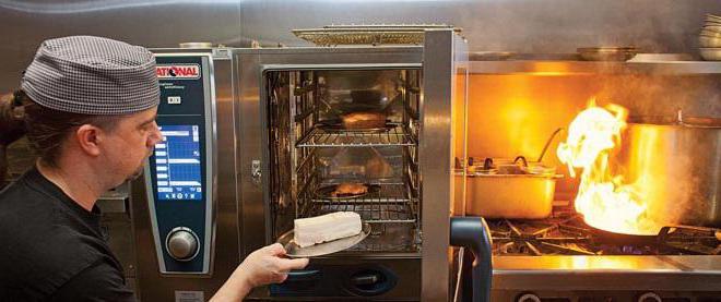
Видными представителями профессиональной кухонной техники этой категории являются пароконвектоматы Rational. На отечественном рынке продукция немецкой компании появилась в 2004 году и сразу зарекомендовала себя с лучшей стороны. История развития оборудования насчитывает более четырех десятков лет. За это время пароконвектоматы вплотную приблизились к идеалу кухонного оборудования.
Устройство пароконвектоматов
Компания Rational существует с 1976 года, ровно с того самого момента, когда господин Майстер изобрел первый в мире пароконвектомат. С тех пор конструкция кухонной техники претерпела значительные изменения. Однако в их устройстве по-прежнему можно выделить две основные секции: камеру для приготовления пищи и блок рабочего оборудования.
Внешне пароконвектоматы Rational представляют собой довольно массивные шкафы, выполненные из нержавеющей стали. На стенках камеры для приготовления пищи установлены нагревательные элементы, на дне имеется специальное сливное отверстие для удаления конденсата при обработке продуктов паром.
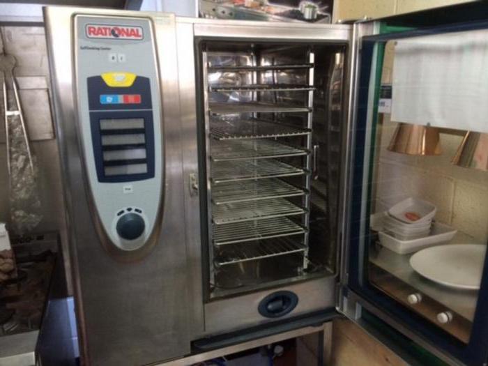
Камера герметично закрывается стальной дверцей с окном из трехслойного жаропрочного стекла. С его помощью повара могут наблюдать за процессом приготовления. Чтобы конденсат, образующийся на дверце, не стекал на пол во время открытия, предусмотрен специальный лоток. Внутри камеры встроен мощный вентилятор, который в одно мгновение доводит температуру рабочей среды до необходимого уровня.
Устройство парогенераторов
Все пароконвектоматы Rational поставляются со встроенным парогенератором, который вместе с автоматикой и пультом управления располагается в блоке рабочего оборудования. Встраиваемые парогенераторы могут быть двух типов: инжекторными и бойлерными.
В первом случае генерация пара происходит за счет распыления воды непосредственно на нагревательные ТЭНы камеры приготовления. Для сбора конденсата в такой технике предусмотрен коллектор и сливное отверстие. Плюсами инжекторных парогенераторов являются доступная цена, простая конструкция и малые габариты всей техники. К минусам можно отнести невозможность регулирования температуры пара.
Бойлерные пароконвектоматы Rational имеют отдельный парогенератор в виде бойлера. В нем при помощи магнитного клапана поддерживается постоянный уровень жидкости. Образование пара происходит за счет нагрева воды внутри емкости. К плюсам таких установок следует отнести высокую производительность и мощность, возможность нагрева пара до 130оС, а к минусам – образование накипи на нагревательных элементах бойлера, высокую стоимость и большие габариты.
Пароконвектоматы SelfCooking Center
Особого внимания среди всей линейки оборудования заслуживают модели SelfCooking Center, призванные учиться у мастера и думать вместе с поваром. Главную роль в этом агрегате играет блок автоматики и различные датчики определения температуры блюда, степени прожарки и подрумянивания.
Одним из представителей серии является пароконвектомат Rational SCC 101. В его программу встроены алгоритмы приготовления блюда индийской, китайской, японской, латиноамериканской кухонь.
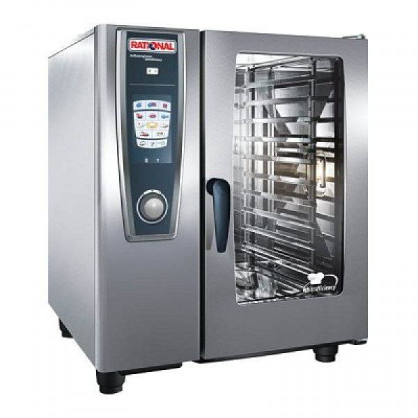
Но главной особенностью аппарата является его способность к обучению. Он запоминает предпочитаемую поваром технологию приготовления и заносит ее себе в память, анализирует и предлагает свой рецепт, а после поэтапно «расписывает» новую методику. Однако последнее слово всегда остается за человеком.
Особенности приготовления блюд
Каким бы опытным поваром вы ни были, перед началом работы с пароконвектоматом внимательно изучите инструкцию. Это позволит избежать травм, ожогов и порчи продуктов.
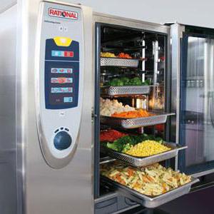
Но часто на пароконвектомат Rational инструкция по эксплуатации напечатана на немецком языке. Для тех, кто столкнулся с подобной проблемой, приведем основные положения из ее содержания:
- для равномерного нагрева пищи перед началом работы прогрейте рабочую камеру в течение 10-15 минут при температуре 130-140оС;
- оставляйте место между продуктами при их загрузке – так вы сократите время приготовления и расход электричества, добьетесь равномерной корочки;
- загружайте продукты максимально быстро, чтобы не изменились условия приготовления внутри рабочей камеры (влажность, давление), ведь это может привести к порче блюд;
- не прислоняйтесь к дверце, не приближайтесь лицом к смотровому окну слишком близко во избежание получения ожогов.
Перед началом работы с техникой производителем рекомендуется повторить элементарные правила техники безопасности при работе с тепловым оборудованием, а также изучить устройство пароконвектомата Rational. Это поможет избежать проблем.
Коды ошибок пароконвектоматов
Как и любая другая умная техника, пароконвектоматы Rational при возникновении неисправностей сообщают об этом пользователю в виде кодов ошибки. Выяснение причины повреждения поможет как можно скорее исправить проблему и продолжить работу. На что обращать внимание при отказе в работе устройств серии SCC, SCC-WE и SCC 5 Senses, смотрите ниже.
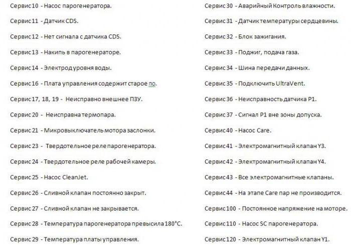
Для устранения неисправностей оборудования лучше всего вызвать квалифицированного специалиста. Но когда это невозможно, внимательно изучите коды ошибок и действуйте в соответствии с инструкцией по эксплуатации.
Ошибки пароконвектоматов серий СМ и СМ Р
Ошибки пароконвектомата Rational, принадлежащего линейке моделей СМ или СМ Р, немного отличаются от представленных ранее. Эта группа оборудования более точно указывает на причину неисправности и помогает ее устранить.
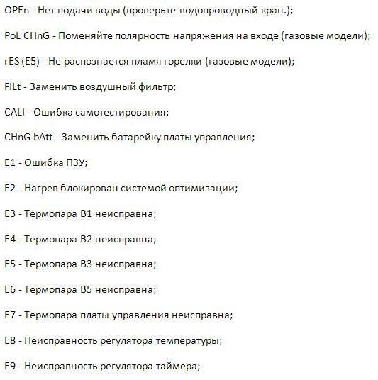
В некоторых случаях во время готовки могут появиться нетипичные коды ошибок. Одной из таковых является Е34, которая является «комбинированным» сигналом. Цифра 3 сообщает об ошибке шины данных, а второе число – в каком именно элементе произошла ошибка. Так, 4 указывает на верхний блок зажигания, а 8 – на нижний; число 2 – на нижний мотор, а 1 – на верхний двигатель.
Если оборудование предприятий общественного питания Rational показывает ошибку Е16, вам следует проверить исправность защитного термостата бойлера, возможно, проблема кроется в реле. Код 34.2 говорит об отсутствии связи между мотором и платой – требуется вызов специалистов. А вот с ошибкой Е51 справится любой, ибо она сообщает, что напряжение батарейки ниже 1,5 В, и ее необходимо заменить.
С заботой и любовью к технике
Пароконвектомат – дорогостоящее, но необходимое и быстро окупаемое оборудование профессиональной кухни. Чтобы свести к минимуму риск серьезной поломки, каждый месяц проводите профилактический осмотр техники. Выявив и устранив мелкие неисправности, вы не дадите развиться проблеме, которая позже остановит всю вашу кухню.
Немецкое оборудование предприятий общественного питания славится своей надежностью и функциональностью, но требует от своих владельцев бережного отношения и внимательного ухода. Не забывайте регулярно чистить и мыть пароконвектомат, ведь загрязнения тоже могут стать причиной поломки. Соблюдая элементарные правила, вы оградите себя от многих неприятностей в будущем.
Пароконвектомат – незаменимая техника на профессиональных кухнях. Поломка такого аппарата является крайне нежелательным явлением для общепита, так как может привести к невозможности подачи заказанного блюда и потере клиентов. В большинстве своем ошибки пароконвектоматов зависят от некорректной эксплуатации оборудования.
Основные правила эксплуатации
- Первый запуск печи проводится с пустой камерой на протяжении получаса и при температуре +200 градусов.
- В начале рабочего дня при загрузке устройства замороженными продуктами или максимально заполнении камеры полуфабрикатами, необходимо провести предварительный нагрев камеры в течение четверти часа при температуре, которая выше стандартного режима на 40 градусов.
- При выкладке сохраняет расстояние между полуфабрикатами не менее 2-х см.
- Открывать камеру во время процесса приготовления рекомендуется как можно реже, чтобы сохранить стабильность температуры.
Важно! Своевременное сервисное обслуживание и ремонт неполадок исключат выход техники из строя и предупредят увеличение расхода электроэнергии.
Пароконвектомат Abat: ошибки
Наиболее частными погрешностями работы ПКА Чувашторгтехника являются:
- Е02 (появляется после нажатия кнопки включения и сопровождается звуковой сигнализацией) – повышение предельной температуры (от +75 градусов) в зоне контроллера либо неисправность последнего.
- Е11 (при выставлении программы «Пар») – закрыт кран, подающий воду на пароконвектомат, либо открыт кран слива воды из бойлера, либо недостаточный уровень воды в устройстве (не покрывает электрод).
- Е04 (при попытке запуска устройства) – обрыв термопары.
Подробно все возможные погрешности в работе агрегата и неисправности описаны в руководстве по эксплуатации.
Ошибки пароконвектомата Unox и Rational
Чаще всего при работе с устройством Унокс встречаются следующие поломки:
- ЕЕ1 – неисправность проводки, соединяющих датчик камеры с источником питания.
- AF01 – перегревание мотора при выполнении функции «конвекция».
- AF02 – запуск аварийной термо-защиты.
- EF4 – перегрев двигателя вентилятора.
Наиболее частые нарушения функциональности устройства Rational серии SCC:
- OPEn – отсутствует подача воды.
- E7 – неисправность термопары платы управления.
- E8 – поломка регулятора температур.
- CHnG bAtt – потребность замены батарейки в блоке управления, пр.
Не представляет сложности расшифровать коды ошибок пароконвектоматов, но не всегда удается самостоятельно исправить поломку даже при наличии соответствующей инструкции. Компания Кобор предлагает не только купить теплотехнику от лучших производителей, но также и услуги по ее обслуживанию и ремонту для жителей Москвы и области. Посмотреть товары и цены можно в каталоге нашего интернет-магазина. Обеспечивается доставка по всей России.
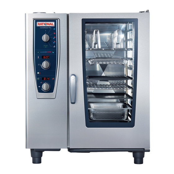
- Manuals
- Brands
- Rational Manuals
- Oven
- CombiMaster Plus CMP 61
- Original operating instructions
-
Contents
-
Table of Contents
-
Bookmarks
Quick Links
CombiMaster
Plus / CombiMaster
®
®
Original operating instructions
Related Manuals for Rational CombiMaster Plus CMP 61
Summary of Contents for Rational CombiMaster Plus CMP 61
-
Page 1
CombiMaster Plus / CombiMaster ® ® Original operating instructions… -
Page 2
FREE OF CHARGE! — RATIONAL ConnectedCooking Connect your RATIONAL appliances easily with the latest network solution for professional kitchens. With ConnectedCooking you always have everything under control: Simple appliance… -
Page 3
RATIONAL SERVICE PARTNERS Our appliances are reliable and have a long service life. However if you should encounter technical difficulties, the RATIONAL SERVICE PARTNERS can provide swift and efficient help. Guaranteed spare parts supply and a weekend call-out team included: Tel. +49 (0) 81 91/327 666. -
Page 4
We give a 24 month warranty calculated from the date of initial installation, providing you have filled in the warranty registration for your appliance completely and correctly. You can do this conveniently online at www.rational-online.com/warranty or using the enclosed postcard. The warranty excludes glass damage, light bulbs and seals as well as damage caused by improper installation, use, maintenance, repair or descaling. -
Page 5
Contents Explanation of the pictograms Initial start-up Safety Instructions Liability Care, inspection, maintenance and repair Function parts Notes on using your appliance Working with the core temperature probe Working with the hand shower Operating controls General notes ClimaPlus ® Overview of modes Steam mode Dry heat mode Combination mode… -
Page 6
Contents Settings Celsius/Fahrenheit Settings Time/Date Cleaning CombiMaster ® Plus Start clean Cleaning programmes CleanJet ® abort Cleaning CombiMaster ® Steam generator descaling display LAN cable connection Network settings Building services — steam generator descaling Building services — steam generator drainage Domestic technology Servicing the air filter Replacing the door gasket… -
Page 7: Explanation Of The Pictograms
Explanation of the pictograms Danger! Warning! Caution! Imminently hazardous Potentially hazardous Potentially hazardous situation, which, if not situation, which, if not situation, which, if not avoided, will result in severe avoided, may result in avoided, may result in slight injuries or death. serious injury or death.
-
Page 8: Initial Start-Up
Initial start-up Please read the manual carefully prior to initial start-up. During initial start-up of your new appliance, you will be requested to start an automatic one- off self-test. This self-test takes about 45 minutes and is used to adapt the appliance to the specific environmental conditions.
-
Page 9
Initial start-up step info/button instructions Open the cooking chamber door and remove the packaging material, starter kit, grids and containers. Insert an empty GN sheet with the opening facing downwards into the rack in front of every fan wheel. Please read the installation instructions for more details. -
Page 10: Safety Instructions
Safety Instructions Keep this manual in a safe place so that it can always be consulted by anyone using the appliance. This appliance may not be used by children or people with limited physical, sensor or mental capacity or those without the necessary experience and/or knowledge, unless such people are supervised by a person who is responsible for their safety.
-
Page 11
IEC 60417-6332 certification allows the setting up of the electric version of the combi- steamer in humid and warm environments. Warning! Smoking food in the appliance Smoking food in the appliance may only be done using the original RATIONAL smoking accessory, VarioSmoker. Warning! No objects on the appliance ceiling. -
Page 12
Safety Instructions Warning! Gas appliances only — If your appliance is installed under an extractor hood, this must be switched on when the appliance is in use — combustion gases! — If your appliance is connected to a chimney, the flue duct must be cleaned in compliance with specific regional regulations — risk of fire! (Contact your installer). -
Page 13: Liability
Safety instructions and liability Warning! Safety instructions during use — When filling containers with liquids or if containers fill up with liquid food products during cooking, only use the rack levels where the user can easily look into the inserted container — risk of burns! Information sticker is enclosed with the unit.
-
Page 14
Safety instructions and liability Liability Installations and repairs that are not carried out by authorised specialists or using original spare parts, and any technical modification that is not approved by the manufacturer will void the manufacturer’s warranty and product liability. 14 / 107… -
Page 15: Care, Inspection, Maintenance And Repair
Care, inspection, maintenance and repair In order to retain the high quality of the stainless steel, for hygienic reasons and to avoid interferences to operation, the appliance must be cleaned daily or when prompted to clean. Follow the instructions in the «Cleaning» section. Constant operation at high cooking cabinet temperatures (≥…
-
Page 16
Care, inspection, maintenance and repair Warning! Inlet filter maintenance The device automatically detects if the air filter is dirty. You will receive a service message and prompt to clean or replace the air filter when it is dirty. The appliance may only be operated without an air filter. -
Page 17
Care, inspection, maintenance and repair Inspection, maintenance and repair Danger — high voltage — Inspection, maintenance and repair work must only be carried out by trained technicians. — The appliance must be disconnected from the mains for cleaning (apart from CleanJet ®… -
Page 18: Function Parts
Function parts Appliance number (only visible when the door is open) Flow guard (optional) (for gas appliances only) Cooking cabinet lighting Appliance door with triple glazing Appliance door with double glazing Door handle Tabletop units: One-handed operation with sure-shut function Standalone appliances: One-handed…
-
Page 19: Notes On Using Your Appliance
Notes on using your appliance — Avoid having heat sources (e.g. grill plates, deep-fat fryers etc.) near the appliance. — Only use the appliance in areas with a room temperature of > 5 °C. For ambient temperatures of less than + 5 °C, you must heat the cooking cabinet to room temperature (>…
-
Page 20
Notes on using your appliance If the maximum load sizes are exceeded, this can damage the appliance. Please also note the maximum load sizes for food in the «Manual Cookbook». Table-top appliance 6 x 2/3 GN with hinging rack — To remove the right hinging rack, hold the top of the hinging rack and press it upwards. -
Page 21
Notes on using your appliance Working with mobile oven racks, mobile plate racks and transport trolleys for table-top units (option) — Remove the hinging rack as described above. — Place the run-in rail on the fixing provided on the appliance’s base. Make sure it is fixed accurately in place (4 pins). -
Page 22: Working With The Core Temperature Probe
Notes on using your unit Working with the core temperature probe Caution! The core temperature probe can be hot – Risk of burns. Always insert the core temperature probe into the thickest point on the product. Make sure that a large part of the probe needle is in the product. Insert the core temperature probe at an angle into the product.
-
Page 23
Notes on using your unit Into the breast meat At the thickest point on the product — Always correctly position the core temperature probe in the park position provided – Risk of damage.! — Do not let the core temperature probe hang out of cooking cabinet – risk of damage. — Remove the core temperature probe from the food before you take the food from the cooking cabinet –… -
Page 24: Working With The Hand Shower
Notes on using your unit Working with the hand shower — If you use the hand shower, please pull the hose at least 20 cm out of the park position. — You can select 2 jet strengths by pressing the control button. — Always let the hand shower slide slowly back into the park position.
-
Page 25: Operating Controls
Operating controls Operating mode switches Steam (30 °C to 130 °C) Convection (30 °C to 300 °C) Combination of steam and convection (30 °C to 300 °C) Finishing (30 °C to 300 °C) Cool down Programming / Start programme and clean Sets humidity / displays number of cleaner and rinse aid tabs…
-
Page 26
Operating controls Air speed Set the cooking time (0 to 23 h 59 min) Set the core temperature (0 °C to 99 °C) Displays cooking time/core temperature/cleaning time Selector switch for cooking time/ core temperature 26 / 107… -
Page 27: General Notes
General notes Operation: Choose the required Choose the required Choose the required cooking mode. cooking cabinet cooking time/core temperature. temperature. The cooking time can be set in minutes for times between 0 and 2 hours, in 5-minute intervals for times between 2 and 3 hours, in 15-minute intervals for times between 3 and 6 hours and in 30-minute…
-
Page 28
General notes Notes: A buzzer signals the end of cooking. The cooking mode display Button lights up when the flashes when the cooking heating is active. cabinet is too hot (see the “Cool Down” section on cooling the cooking cabinet). Fault messages: … -
Page 29: Climaplus
ClimaPlus ® ClimaPlus® measures and regulates the humidity in the cooking cabinet. You can set the exact product-specific climate for each food in the climate window. Steam: Dry heat: Steam + dry heat: The factory setting for You can set the mixture ClimaPlus allows you to ®…
-
Page 30
ClimaPlus ® Press the cooking time or core temperature button to display the current humidity in the cooking cabinet. For continuous operation that is as resource friendly as possible, we recommend using standard cooking cabinet humidity e.g. 100% for dry heat. 30 / 107… -
Page 31: Overview Of Modes
Overview of modes Steam mode (30 °C to 130 °C) The high performance fresh steam generator with new steam control always produces hygienic fresh steam. You can cook without adding water and without waiting for the water to boil. Constant cooking cabinet temperatures and maximum possible steam saturation guarantee a uniform and highly gentle cooking process.
-
Page 32
Overview of modes «Cool down» With the Cool Down function, you can quickly and gently cool a hot cooking cabinet, e.g. for low temperature cooking or manual cleaning. Programming/Programme Start/ Cleaning» Using the programming function, create and save manual programmes. For recurring cooking processes, there are 100 programme slots with up to 6 cooking steps available. -
Page 33: Steam Mode
Steam mode In the “steam” cooking mode, the steam generator generates hygienic fresh steam. You can set the cooking cabinet temperature from 30 °C to 130 ℃ . Cooking methods: Steaming, stewing, blanching, simmering, soaking, vacuum cooking, thawing, preserving step info/button instructions Choose the “steam”…
-
Page 34
Steam mode — After preheating and loading, an acoustic signal and the 00:00 setting in the display will remind you that you still have to set the required cooking time or core temperature. — If no further action takes place after the preheat temperature is reached, heating mode is switched off after 10 minutes. -
Page 35
Steam mode Sample dishes Mise en place Tomatoes concassé, garnishes (vegetables, fruit), mushrooms, blanching juliennes and brunoises, blanching vegetables for stuffings, roulades etc., peeling onions and chestnuts, soaking pulses, blanching bacon and ham, poaching fish dishes, soups, sauces, stocks, fumets etc. -
Page 36
Steam mode To get the most out of your appliance, check daily the types of food which can be cooked together using “steam” . Remember that fish, meat, vegetables, side dishes and fruit can be cooked together (as long as they are all being prepared by the same method). -
Page 37: Dry Heat Mode
Dry heat mode In “dry heat” cooking mode, powerful heating elements heat up the dry air. You can set the cooking cabinet temperature from 30 °C to 300 °C . You can limit the cooking cabinet humidity if necessary. Cooking methods: Baking, roasting, grilling, deep-frying, gratinating, glazing. step info/button instructions…
-
Page 38
Dry heat mode — After preheating and loading, an acoustic signal and the 00:00 setting in the display will remind you that you still have to set the required cooking time or core temperature. — If no further action takes place after the preheat temperature is reached, heating mode is switched off after 10 minutes. -
Page 39
Dry heat mode Sample dishes Mise en place Sweating bacon, roasting bones, allowing dough (yeast) to rise. Starters Meatballs, vegetarian bakes, vegetables au gratin, vegetable pasties, pies, sirloin, chicken wings, finger food, duck breasts, quiches, shortcrust pastry, tartlets. … -
Page 40
Dry heat mode Cooking times Cooking times will depend on product quality, weight and height. Do not overload grids or containers so that air can circulate evenly. General notes on pan-frying — Preheat to as high a temperature as possible (300 °C) to build up sufficient stored heat. — load as quickly as possible, in order to minimise cabinet temperature drop. -
Page 41: Combination Mode
Combination mode The two operating modes “steam” and “dry heat” are combined. This combination creates a hot humid cabinet climate for especially intensive cooking. You can set the cooking cabinet temperature from 30 °C to 300 °C . You can set the cooking cabinet climate if necessary. Cooking methods: Roasting, baking, finishing.
-
Page 42
Combination mode — After preheating and loading, an acoustic signal and the 00:00 setting in the display will remind you that you still have to set the required cooking time or core temperature. — If no further action takes place after the preheat temperature is reached, heating mode is switched off after 10 minutes. -
Page 43
Combination mode Sample dishes Mise en place Roasting bones. Starters Quiche Lorraine, vegetable soufflés, flans, moussaka, lasagne, canneloni, paella, pasta bakes. Main courses Roasts (beef, veal, pork, lamb, poultry, game), roulades, stuffed vegetables (peppers, aubergines, cabbage, onions, kohlrabi), vegetable gratins (cauliflower), turkey legs, stuffed breast of veal, ham with noodles, leg of pork, belly of pork, various omelettes. -
Page 44
Combination mode Do not place joints too close together to allow even cooking. Joints with rinds or larger joints should be steamed for approximately 1/3 of the cooking time. Collect condensate in a container (additional rail) and make the gravy by adding it to the lightly roasted bones. -
Page 45: Finishing ® Cooking Mode
Finishing ® cooking mode The two operating modes steam and dry heat are combined. This produces the ideal cooking climate, both preventing the food drying out and the formation of unwanted puddles. You can set the cooking cabinet temperature from 30 °C to 300 ℃ . step info/button instructions…
-
Page 46: Cooking Mode
Finishing ® cooking mode — After preheating and loading, an acoustic signal and the 00:00 setting in the display will remind you that you still have to set the required cooking time or core temperature. — If no further action takes place after the preheat temperature is reached, heating mode is switched off after 10 minutes.
-
Page 47
Finishing ® cooking mode Sample dishes Starters All types of spaghetti, canneloni, lasagne, vegetable dishes, cheese and herb noodles, quiche Lorraine, spring rolls, vegetarian cutlets, onion flans. Main courses All types of roast, meat loaves, bakes, ready-to-serve meals, roulades, stuffed vegetables. … -
Page 48
Finishing ® cooking mode Finishing utensils Porcelain plates, earthenware, glass, silverware, copper pans, stainless steel, aluminium dishes (brought in). Banqueting service/tour groups Reheat plates in the mobile plate rack. – Large quantities in next to no time. – Fast loading and unloading. –… -
Page 49: Cool Down
Cool down You have been operating your appliance at high cooking cabinet temperatures at first and then want to continue working at low cabinet temperature. You can cool the cooking cabinet down quickly but gently using “cool down”. Warning! — Do not use the “cool down” function unless the air baffle has been locked correctly – risk of injury.
-
Page 50: Program Mode
Program mode You use the programming function to create and save programs manually. There are 2×50 program slots available with up to 6 cooking steps each for repeat cooking processes. So that you can guarantee constant quality – even when you have assistants doing the cooking. Create program step info/button…
-
Page 51
Program mode step info/button instructions Press the button to set the cooking time. Set the required cooking time Press the button. Select a further cooking mode e.g. “dry heat”, and this is confirmed by “S2” appearing on the display. Set the required cooking time Select the required cooking cabinet humidity or work with the default setting. -
Page 52
Program mode step info/button instructions Choose the required core temperature. Press the button. Use the selection button to set “Prog/Clean | Start” to save the program. — Activate the “Prog/Clean | Start” button for programming again if it has gone out. — If you would like to keep the same cooking mode in the next program step, choose another cooking mode briefly in order to be able to start the next program step. -
Page 53: Check Program
Program mode Check program step info/button instructions Use the selection button to set “Prog/Clean | Start”. Choose the required program. Start the program by pressing “Prog/Clean | Start”. 53 / 107…
-
Page 54
Program mode — If the display flashes, it means the program slot is vacant. — The remaining cooking time is shown during operation in the “cooking time/core temperature” display. If the program includes a step with core temperature, the remaining time is only shown when this step has been finished. -
Page 55: Check Program
Program mode Check program step info/button instructions Use the selection button to set “prog/start”. Choose the required program. Press “prog/start” to show the first program step. Press the button again to request the next step. The cooking cabinet door should be open. — If the display flashes, it means the program slot is vacant.
-
Page 56: Delete Program
Program mode Delete program step info/button instructions Use the selection button to set “prog/start”. Select a program, e.g. P4. Keep the “prog/start” button pressed for 5 seconds. A flashing program slot confirms deletion. Individual program steps can neither be deleted nor changed. 56 / 107…
-
Page 57: Download Programme
Download Programme Use the download function to save your own programs to a USB stick. The USB stick should be connected when the unit is switched off. step info/button instructions Switch the unit off and insert the USB stick in the slot underneath the control panel.
-
Page 58
Download Programme step info/button instructions When the process has been completed, “end” appears on the display. Remove the USB stick. 58 / 107… -
Page 59: Upload Programme
Upload Programme — Connection of energy optimisation system. Copy your individual cooking porgrams to the unit with the upload function. The USB stick should be connected when the unit is switched off. step info/button instructions Switch the unit off and insert the USB stick in the slot underneath the control panel.
-
Page 60
Upload Programme step info/button instructions When the process has been completed, “end” appears on the display. Remove the USB stick. When the upload function is used, all program slots on the unit are overwritten. Back up existing programs on a USB stick before you transfer programs from another unit. 60 / 107… -
Page 61: Haccp
HACCP The data is stored for a period of 10 days and can be output via the USB interface on the unit as required.. To save HACCP data permanently on a USB stick, please follow the instructions. The USB stick should be connected when the unit is switched off. step info/button instructions…
-
Page 62
HACCP step info/button instructions When the process has been completed, “end” appears on the display. Remove the USB stick. The following data is logged: — Batch no. — Time — Cooking program name — Cooking cabinet temperature — Core temperatura — -Door open /door closed — Change of cooking mode — Connection of energy optimisation system. -
Page 63: Software Update
Software update The unit software can be updated with a USB-Stick. The USB stick should be connected when the unit is switched off. step info/button instructions Switch the unit off and insert the USB stick in the slot underneath the control panel. Keep the “ClimaPlus”®…
-
Page 64: Settings Celsius/Fahrenheit
Settings Celsius/Fahrenheit The temperatures of your unit can be shown in Celsius or Fahrenheit. To change the display, proceed as follows. step info/button instructions «Prog/Start» press Turn the selection button clockwise. Appears on the display. Press the button. The temperatures of your unit can be shown in Celsius or Fahrenheit.
-
Page 65
Settings Celsius/Fahrenheit step info/button instructions Press the button to save the setting. 65 / 107… -
Page 66: Settings Time/Date
Settings Time/Date You can set the time and date on your unit for correct evaluation of HACCP data. Carry out the settings as follows. step info/button instructions «Prog/Start» anwählen Turn the selection button clockwise. Appears on the display. Press the button. Shown on the upper display for the hour setting.
-
Page 67
Settings Time/Date step info/button instructions Turn the lower selection button to set the hour and save this using the “prog/start” button. Shown on the upper display for the minute setting. The current day appears in the lower display. Turn the lower selection button to set the hour and save this using the “prog/start”… -
Page 68: Start Clean
Cleaning CombiMaster Plus ® Start clean CleanJet is the automatic cleaning system for cleaning the cooking cabinet. The 3 ® cleaning programmes allow you to adapt the cleaning process to the particular level of soiling. Attention! — For hygiene reasons and to prevent malfunctions it is essential to clean your appliance every day — risk of fire! — Your appliance must be cleaned every day, even if it is only operated in «Steam»…
-
Page 69
Cleaning CombiMaster Plus ® step info/button instructions Turn the temperature selector switch to the right to select the desired cleaning programme «CLE1», «CLE2» or «CLE3». Depending on the cleaning programme selected, either «CLE1», «CLE2» or «CLE3» will appear on the display. Press the button. -
Page 70
Cleaning CombiMaster Plus ® step info/button instructions Now open the cooking cabinet door to add the Open the door cleaner and rinse aid tabs. Warning! Always wear protective gloves to handle the cleaner tabs — risk of chemical burns. Unpack the displayed number of rinse aid tabs and place the tabs in the tab basket. -
Page 71
Cleaning CombiMaster Plus ® Warning! — Do not open the cooking cabinet door while cleaning is in progress – chemical cleaner and hot vapour may escape – risk of chemical burns and scalding. A horn sound is heard if the door is opened during the cleaning process. — Once the CleanJet cleaning process is aborted or has ended, check the entire cooking ®… -
Page 72
Cleaning CombiMaster Plus ® Chemical handling instructions Warning! Only use cleaner and rinse aid tabs in compliance with the relevant safety measures, always wear, for example, protective gloves when handling the tabs — risk of chemical burns! Rinse aid tab: Remove Place the rinse aid tab with exterior protective film the transparent protective… -
Page 73
Cleaning CombiMaster Plus ® Before starting the CleanJet clean, make sure that the hinging racks or mobile oven rack are ® correctly inserted in the cooking cabinet. When using softened water, the recommended quantity of cleaning tabs can be reduced by up to 50%. -
Page 74: Cleaning Programmes
Cleaning CombiMaster Plus ® Cleaning programmes cleaning stage description/application tabs «Powerful clean» For heavy roasting and grilling deposits, e.g. CLE1 Cleaner & rinse aid multiple loads of chicken, steaks, etc. Duration approx. 3 hours 45 minutes. Economical clean — «Eco» For light soiling (up to 200°C) with the most CLE2 Cleaner &…
-
Page 75
Cleaning CombiMaster Plus ® CLE2 Appliance No soft water Soft water Duration Cleaner tabs Rinse Cleaner tabs Rinse aid tabs aid tabs 6x 2/3 GN 02:30 h:mm 6x 1/1 GN 02:30 h:mm 10x 1/1 GN 02:30 h:mm 6x 2/1 GN 02:30 h:mm 10x 2/1 GN 02:30 h:mm… -
Page 76: Cleanjet ® Abort
Cleaning CombiMaster Plus ® CleanJet abort ® In the event of a power outage or after switching off the appliance, «StOP» will appear in the temperature display and the «Prog/Clean | START» button will blink. If the «Prog/Clean | START» button is not pressed, the clean will run for another 30 seconds. To abort, the «Prog/Clean | START»…
-
Page 77
Cleaning CombiMaster Plus ® step info/button instructions The word «rInS» will then appear in the temperature display and the full humidity display will flash blue. The word «cAb» will also appear on the time display. Open the door Open the door. Rinse out the cooking cabinet (behind the air baffle too) with water. -
Page 78
Cleaning CombiMaster Plus ® Abort if the cleaner or rinse aid tabs have come into contact with water step info/button instructions «STOP» will appear in the temperature display To abort, the «Prog/Clean | START» button must be pressed. If the abort operation is confirmed, «tAb» and «out»… -
Page 79
Cleaning CombiMaster Plus ® 79 / 107… -
Page 80
Cleaning CombiMaster Plus ® If no water has yet been introduced into the cooking cabinet at the time of aborting or if a defined time has not yet passed, the abort programme will not run. This means that the cooking cabinet will not be automatically rinsed with water. -
Page 81: Cleaning Combimaster
Cleaning CombiMaster ® Warning! — For hygiene reasons and to prevent malfunctions it is essential to clean the unit every day — risk of fire. — Please note that your unit must be cleaned every day, even if only “steaming” mode is used. — Follow the safety instructions on the spray bottle and cleaner canister.
-
Page 82
Cleaning CombiMaster ® step info/button instructions Spray the space behind the air baffle, cooking cabinet, door seal and inside of the door with cleaner. Reset and lock the air baffle and hanging rack in place, close the cooking cabinet door. Warning! Do not open the cooking cabinet door while cleaning is in progress –… -
Page 83
Cleaning CombiMaster ® step info/button instructions At the end of the cleaning time, you will be prompted to open the doors. When the cleaning program has finished, rinse the unit down, including behind the air baffle. Wipe the cooking cabinet and cooking cabinet seal with a damp cloth. -
Page 84
Cleaning CombiMaster ® If there is a power failure during cleaning, the following warning appears: The cleaning program must be cancelled in these circumstances. This is achieved by pressing the Prog/Start button. The device must then be rinsed manually! Warning! Aggressive chemical fluid –… -
Page 85: Steam Generator Descaling Display
Steam generator descaling display Your appliance is equipped with the CleanJet® automatic cleaning system. The steam generator in your appliance still needs regular descaling, depending on water hardness and use. The descale level of your steam generator is determined with Calc Info. Once a critical level of scale is reached, the unit display will indicate that the steam generator should be descaled.
-
Page 86: Lan Cable Connection
LAN cable connection The following manual describes how to connect a LAN cable to the LAN interface of your appliance. The LAN interface is located Unscrew the splash Thread the individual on the underside on the left protection cover. components on the cable, side of the appliance (for as shown in the diagram.
-
Page 87
LAN cable connection Danger of burns. When laying the LAN cable underneath the unit floor, make sure they do not come in contact with hot components Do not wrap the LAN cable around hot components. The assembly and splash protection can only be guaranteed if you use an Ethernet cable with the following specifications: Maximum plug length of the Ethernet plug 45 mm Maximum plug diameter diagonally of 18.5 mm… -
Page 88: Network Settings
Network settings How to configure the network settings on your unit is described below. The following settings may be made: IP address Subnet mask Gateway step info/button instructions Turn the top dial to the «Prog/Clean | START» button. Turn the temperature selector to the right until «IP»…
-
Page 89
Network settings step info/button instructions Confirm the number with the «core temperature» button. Now turn the temperature selector slightly to the right until «IP 2» appears on the temperature display. Now you can enter the second position of the IP address. E.g. 10.10.x.x Next the subnet mask must be entered. -
Page 90: Building Services — Steam Generator Descaling
Building services — steam generator descaling The steam generator must be descaled manually on a regular basis. We recommend the following descaling intervals based on 8 hours’ steaming per day: — up to 18 °dH (to 3.2 mmol/litres) at least 1x annually — up to 24 °dH (to 4.3 mmol/litres) at least 2x annually — over 24 °dH (to 4.3 mmol/litres) at least 3x annually These recommended descaling intervals may vary from the approximate values given above,…
-
Page 91
Building services — steam generator descaling step info/button instructions Turn the selector switch to the right appears in the display. Press the button. The descaling process is started. If the cooking cabinet temperature is over 40 °C when descaling commences, «Cool Down»… -
Page 92
Building services — steam generator descaling step info/button instructions Guide hose into steam inlet opening as far as the mark. Tip: The allocation of marks to appliance size is described in the instructions for the descaler pump. Warning! Aggressive chemical fluid – risk of chemical burns. -
Page 93
Building services — steam generator descaling step info/button instructions Descaling quantities for electric appliances 6 x 2/3 GN 10 x 1/1 GN 20 x 1/1 GN 1.8 litres 6 litres 9 litres 6 x 1/1 GN 10 x 2/1 GN 20 x 2/1 GN 3.5 litres 8.5 litres… -
Page 94
Building services — steam generator descaling step info/button instructions Close the cooking cabinet door. The length of the descaling phase is displayed. The steam generator is automatically rinsed several times. The appliance then automatically switches to Steam. «End” appears on the display when descaling is complete. -
Page 95
Building services — steam generator descaling step info/button instructions Switch appliance off and wait for 4 seconds. Switch on the appliance. Descaling will be aborted if the core temperature button is pressed within 30 seconds. If the core temperature button is not pressed within 30 seconds descaling will continue. -
Page 96: Building Services — Steam Generator Drainage
Building services — steam generator drainage You can drain the steam generator before transportation or for frost protection. step info/button instructions Close the water hose and open the doors Set «Prog/Clean | Start» with the selector switch. Turn the selector switch to the right «ESG»…
-
Page 97: Domestic Technology
Air filter no.: 40.03.461 Standalone appliances 20 x 1/1 GN and 20 x 2/1 To replace air filters for standalone appliances 20 x 1/1 GN and 20 x 2/1 GN, please notify your Rational Service Partner! 97 / 107…
-
Page 98: Replacing The Door Gasket
No.: 20.00.399 Replacing the lamps LED lighting To replace the LED lighting, please contact your authorised RATIONAL Service Partner. Changing the halogen lamp First switch off the appliance at the mains. — Cover the appliance drain in the cooking cabinet.
-
Page 99: Service Notifications
Service notifications Should a fault occur in your appliance, this will be indicated on the display. step info/button instructions Faults in your appliance that allow the user to continue using the unit for cooking can be disabled by pressing the clock button. fault indication when and how remedial action…
-
Page 100
Service notifications fault indication when and how remedial action After switching on for Notify customer service! 30 seconds. Is displayed Please check and replace the air filter under continuously the control panel. Check whether an external heat source is affecting the appliance. If the service notification remains — notify customer service! Is displayed… -
Page 101
Service notifications fault indication when and how remedial action On occurrence of the Cooking time/core temperature selector error. switch defective. — Notify customer service! Must be confirmed Steam mode and combi-steam mode not at the end of the available — notify customer service. cleaning programme. -
Page 102: Before You Call Service
Before you call Service: error possible cause Rectification Water dripping out of Door is not closed If the door is closed correctly, the door the unit’s door. correctly. handle will point down on floor units. Door seal is worn or Replace the door seal (see the damaged.
-
Page 103
Before you call Service: of fat are cooked frequently or if the drop on the outlet pipe is too shallow. To remedy: Run the outlet pipe as described in the installation instructions. The unit does not External main switch is Switch on at the main switch indicate a function switched off… -
Page 104: Eu Declaration Of Conformity
EU Declaration of Conformity 104 / 107…
-
Page 105
EU Declaration of Conformity 105 / 107… -
Page 106
EU Declaration of Conformity 106 / 107… -
Page 108
80.02.407 V-02 MDS/Ad 09/17…

Сообщения об ошибках Rational SCC
Rational SCC не только упрощает приготовление пищи, но также имеет несколько полезных
функций для техников, которые обслуживают оборудование. Возможно, одной из лучших функций машины
является возможность предлагать диагностические коды. Каждый код сообщит вам, что не так с пароконвектоматом,
что позволит вам быстрее решить проблему.
| Сервис 10 | Насос парогенератора | — Индикация на дисплее в течение 30 с после включения — Отмена индикации – символ «возврат» на дисплее 1 — Насос парогенератора не произвел откачку — Проверить насос парогенератора |
| Сервис 11 | Датчик CDS — провести техобслуживание |
— Индикация на дисплее в течение 30 с после включения — Отмена индикации – символ «возврат» на дисплее 1 — Слишком много импульсов с датчика импульсов CDS — Проверить электрод уровня или герметичность стопорного клапана |
| Сервис 12 | Нет сигнала с датчика CDS — провести техобслуживание |
— Индикация на дисплее в течение 30 с после включения — Отмена индикации – символ «возврат» на дисплее 1 — Электрод уровня воды работает нормально
— Проверить датчик системы диагностики накипи (возможно засорение) – |
| Сервис 13 |
Накипь в парогенераторе — провести техобслуживание |
— Возможно приготовление только в режиме «Сухой жар» — Нет сигнала о понижении уровня воды в парогенераторе за последние — принудительное наполнение — Проверить сигнал «1-0» от электрода уровня воды. |
| Сервис 14 |
Электрод уровня воды — провести техобслуживание Возможно приготовление только в режиме «Сухой жар» |
— Индикация на дисплее в течение 30 с после включения — Отмена индикации – символ «возврат» на дисплее 1 — Электрод уровня не «чувствует» воду.
— Датчик системы диагностики уровня накипи работает исправно |
| Сервис 15 |
Не используется | —————————— |
| Сервис 16 |
Плата управления содержит старое ПО Требуется обновить программное обеспечение аппарат не работает |
— Индикация на дисплее в течение 30 с после включения — Данное сообщение активно только начиная с версии ПО 01-07-09 |
| Сервис 17 |
Неисправно внешнее ПЗУ — Не определяется внешнее ПЗУ аппарат не работает |
— Индикация на дисплее в течение 30 с после включения — Данное сообщение активно только начиная с версии ПО 01-07-09 — Нарушена структура данных внешнего ПЗУ – необходима замена ПЗУ |
| Сервис 18 | Не используется | НЕ ИСПОЛЬЗУЕТСЯ |
| Сервис 19 |
Не используется | НЕ ИСПОЛЬЗУЕТСЯ |
| Сервис 20 |
Термопара B1 аппарат не работает |
— Индикация на дисплее появляется в момент выхода из строя термопары — Звуковой сигнал активен в течение 30 секунд — Аппарат не работает |
| Сервис 21 |
Микровыключатель мотора заслонки — провести техобслуживание |
— Индикация на дисплее в течение 30 с после включения — Отмена индикации – символ «возврат» на дисплее 1 — Неисправен выключатель мотора заслонки
— Возможно приготовление только в ручном режиме без контроля |
| Сервис 22 |
Не используется | НЕ ИСПОЛЬЗУЕТСЯ |
| Сервис 23 |
ТЭНы парогенератора SSR пар короткое замыкание |
— Данное сообщение активно только начиная с версии ПО 01-07-09 — Индикация появляется если в течение 60 секунд температура B5 100°C — Прерывистый звуковой сигнал в течение 30 секунд. — Аппарат не работает |
| Сервис 24 |
ТЭНы рабочей камеры SSR горячий короткое замыкание |
— Данное сообщение активно только начиная с версии ПО 01-07-09 — Индикация появляется если в течение 60 секунд температура B1 поднимается — Прерывистый звуковой сигнал в течение 30 секунд. — Аппарат не работает |
| Сервис 25 |
Насос CleanJet — вода не найдена — CleanJet не работает выполнить промывку вручную! |
— Индикация появляется во время работы автоматической мойки CleanJet — Отмена индикации – символ «возврат» на дисплее 1 — Насос CleanJet M6 не подаёт воду, нет торможения мотора вентилятора. — Убрать гастроёмкости из рабочей камеры — Проверить кран подачи воды, клапан подачи воды в коллектор, сопло |
| Сервис 26 |
Сливной клапан постоянно закрыт |
— Индикация появляется при выборе автоматической мойки CleanJet. — Приготовление блюд невозможно — закрыт слив. — Микровыключатель сливного клапана постоянно в закрытом положении. — Заменить узел шарового клапана |
| Сервис 27 |
Сливной клапан не закрывается -Шаровый клапан постоянно открыт. Автоматическая мойка CleanJet невозможна провести техобслуживание |
— Индикация на дисплее в течение 30 с после включения — Отмена индикации – символ «возврат» на дисплее 1 — Микровыключатель шарового клапана постоянно в открытом положении — Автоматическая мойка невозможна, проверить микровыключатель клапана. — Заменить узел шарового клапана. |
| Сервис 28 |
Температура парогенератора превысила 180°C — требуется техобслуживание |
— Индикация показана на дисплее под кнопкой “Service” — Индикация появляется если температура B5 выше 180°C — Сообщение исчезает, когда температура B5 парогенератора опустится |
| Сервис 29 |
Температура платы управления Рекомендация — заменить воздушный фильтр |
— Индикация появляется после включения и присутствует до тех пор. — Температура платы управления превысила 85°C — Проверить воздушный фильтр, вентилятор охлаждения и уплотнение — Проверить, наличие внешних источников тепла рядом с аппаратом. |
| Сервис 30 |
Аварийный Контроль влажности *Аппарат работает в аварийном режиме |
— Индикация на дисплее в течение 30 с после включения — Отмена индикации – символ «возврат» на дисплее 1 — Неисправен контроль влажности. — Аварийный контроль влажности активен более 1-ого часа. — Начиная с версии ПО 01-07-04 индикация состояния аварийного контроля |
| Сервис 31 |
Датчик температуры сердцевины — Сервис 31.xx Термокерн |
— Индикация на дисплее в течение 30 с после включения — Отмена индикации – символ «возврат» на дисплее 1 — Неисправен датчик контроля температуры сердцевины. — Используется шестнадцатизначный код , например: 31.10=2+8 — 31.2: неисправна термопара В10 |
| Сервис 32 | Блок зажигания — Сервис 32.0-2 |
— Данное сообщение активно только начиная с версии ПО 01-07-09 — Внутренняя ошибка блока зажигания присутствует более 30 секунд. — 32.0: Неисправен верхний блок зажигания — 32.1: Неисправен нижний блок зажигания — 32.2: Неисправны оба блок зажигания — Заменить соответствующий блок(и) зажигания |
| Сервис 33 |
Поджиг, подача газа — Сервис 33.1-2 блок зажигания |
— Индикация появляется после четырех безрезультатных попыток поджига — 33.1: верхний блок зажигания — 33.2: нижний блок зажигания — Проверить проводку блоков зажигания, блок зажигания, газовый клапан и |
| Сервис 34 |
Шина передачи данных — Сервис 34.xx Отсутствует сигнал шины |
— Данное сообщение активно только начиная с версии ПО 01-07-02 — Сообщение появляется если присутствует ошибка сигнала шины. — Используется шестнадцетиричный код , например: 34.10=2+8 — 34.2: нижний мотор вентилятора — 34.4: верхний мотор вентилятора — 34.8: верхний блок зажигания — 34.16: нижний блок зажигания — Проверить кабель шины передачи данных, разъем кабеля на наличие |
| Сервис 40 |
Насос Care неисправен или подаёт слишком малое кол-во раствора. |
Насос Care неисправен или подаёт слишком малое количество раствора — после подачи химических средств для ухода за аппаратом поступает — Cleanjet выполняется без фазы очистки парогенератора от накипи; — для сброса ошибки нажать кнопку «Проверить функцию Care» после |
| Сервис 41 |
Электромагнитный клапан Y3 — впрыск воды не работает |
— электромагнитный клапан Y3 неисправен или забита форсунка впрыска — сброс ошибки при успешном измерении CDS в ходе следующего запуска |
| Сервис 42 |
Электромагнитный клапан Y4 — не работает клапан |
— электромагнитный клапан Y4 Care неисправен или шланг подачи воды к — сброс ошибки при успешном измерении CDS в ходе следующего запуска |
| Сервис 43 |
Все электромагнитные клапаны — Сервис 43 Y1, Y3 или Y4 — Все электромагнитные клапаны не работают |
— датчик CDS постоянно шлет импульсы; электромагнитный клапан Y1, Y3 — сброс ошибки при успешном измерении CDS в ходе следующего запуска |
| Сервис 44 |
На этапе Care пар не производится — термопара В5 неисправна при мойке |
— во время мойки Cleanjet термопара B5 не сообщает о повышении — сброс ошибки при успешном измерении В5 в ходе следующего запуска |
| Сервис 100 |
постоянное напряжение на моторе — главный аварийный выключатель. *Аппарат не работает отключить аппарат от электросети! |
— Неисправен главный контактор K1 или выключатель вкл./выкл. Операторской платы управления |
| Сервис 110 |
Насос SC парогенератора *Аппарат не работает |
— Неисправен главный контактор K1 или выключатель вкл./выкл. Операторской платы управления |
| Сервис 120 |
Электромагнитный клапан Y1- Насос CARE, электрод уровня воды. |
— после подачи химических средств для ухода за аппаратом в парогенератор — насос Care M12 или датчик уровня неисправен — сообщение выводится только после второй попытки запуска Y1, если — сброс ошибки при успешном выполнении программы прерывания мойки |
Звуковые сигналы при неиcправности термопары Rational
Частота звукового сигнала при неисправности термопары (количество за 5 секунд)
| B1 | 12 раз в течении 5-ти секунд |
| B2 | 6 раз в течении 5-ти секунд |
| B4 | 5 раз в течении 5-ти секунд |
| B5 | 8 раз в течении 5-ти секунд |
| Термозонд | 20 раз в течении 5-ти секунд |