|
Type |
Point |
Description |
|
A01 |
201 |
Master-positioning sensor does not go ON even after the write pulse motor is activated during the master-positioning, master-cut, or master-loading operation. |
|
A01 |
202 |
Master-positioning sensor does not go OFF even when the write pulse motor is reversed during the master-positioning or at start of master-making operation. |
|
A01 |
206 |
Timeout error during master-making operation |
|
A01 |
211 |
Master-positioning sensor is ON during standby. |
|
A01 |
214 |
Master-positioning sensor is ON at the start of master making. |
|
A01 |
215 |
Faulty gate-array control for the write pulse motor (motor does not stop within set time) |
|
A02 |
509 |
Master-loading sensor was OFF when the master was checked at a specified drum angle during the master-loading operation. |
|
A04 |
303 |
Master-disposal jam sensor was OFF at both 120 and 180 degrees drum angle. |
|
A04 |
314 |
Master-disposal error (recovery error). |
|
A05 |
304 |
Master-disposal jam sensor was ON at the completion of the master-disposal operation. |
|
A05 |
312 |
The master-disposal jam sensor was ON at the start of master-making operation. |
|
A05 |
315 |
The master-disposal jam sensor was ON when the master disposal box was set in the machine. |
|
A06 |
403 |
Paper-feed-tray upper or lower safety switch is OFF. |
|
A07 |
409 |
Paper-ejection sensor was OFF when the paper should have arrived, and the paper sensor was ON when the machine stopped (Paper misfeed). |
|
A07 |
412 |
Paper sensor was OFF three times in succession when a paper misfeed was detected (paper misfeed). |
|
A07 |
413 |
Paper sensor was ON when the paper should have left the paper sensor (long-length paper mode error). |
|
A07 |
418 |
The paper sensor was ON at the start of machine operation when the START button was pressed. |
|
A07 |
429 |
Paper feed error (recovery error). |
|
A07 |
432 |
Paper sensor was ON when the machine went into paper feed retry movement after a paper misfeed. |
|
A08 |
410 |
Paper-ejection sensor was OFF when paper should have arrived, and the paper sensor was OFF when the machine stopped (paper jam on the print drum). |
|
A08 |
421 |
Paper sensor was ON when the paper should have left the paper sensor during feeding of long paper in long-length paper mode (paper longer than 555 mm). |
|
A08 |
430 |
Paper jam on print drum (recovery error). |
|
A09 |
411 |
Paper-ejection sensor was ON when the paper should have left the paper-ejection sensor. |
|
A09 |
417 |
Paper-ejection sensor was ON at the start of machine operation when the START button was pressed. |
|
A09 |
431 |
Paper-ejection error (recovery error). |
|
A10 |
102 |
Original-registration-sensor remaining jam |
|
A10 |
103 |
Original-IN-sensor remaining jam |
|
A10 |
105 |
Original-registration-sensor non-arrival jam |
|
A10 |
106 |
Original-IN-sensor non-arrival jam |
|
A10 |
107 |
Original-OUT-sensor non-arrival jam |
|
A10 |
109 |
An original feed error occurred, due to opening the AF. |
|
A10 |
162 |
No original in AF during AF master making. |
|
A16 |
525 |
Waiting for the master to be removed. |
|
A17 |
209 |
Cutter home-position switch is OFF at the start of master-making or master-set operation. |
|
A34 |
218 |
Request to resetting the master. |
|
B01 |
730 |
Keycard counter: No card |
|
B22 |
721 |
With the «Tape separation» function set ON, no power is supplied to the job separator when start key is pressed. |
|
B22 |
727 |
After cluster-A signal turned ON, BUSY-signal stayed «L» more than 7 seconds (power to job separator was turned OFF while the tape is being ejected. |
|
B23 |
722 |
With the «Tape separation» function set ON, no tape detected in the job separator when the start key is pressed. |
|
B23 |
723 |
No tape remains in job separator upon completion of the tape-ejection operation. |
|
B24 |
724 |
Tape jam detected when the start key is pressed with the «Tape separation» function set to ON. |
|
B24 |
725 |
Job separator tape-jam detection signal is «H» within 1,200 milliseconds after the cluster-A signal turns ON (tape misfeed). |
|
B24 |
726 |
Job separator tape-jam detection signal is «L» when the BUSY signal changes from «L» to «H» (or after 7 sec. at «L») after the cluster-A signal goes ON (tape misfeed). |
|
B31 |
916 |
Network cable is not connected when the machine is powered ON. |
|
B32 |
917 |
Communication error on the network. |
|
B32 |
920 |
Error detected by Network Interface Card (NIC) — NAK (negative acknowledgement was received). |
|
B33 |
931 |
DHCP server is not found with DHCP ON. |
|
B34 |
919 |
Error detected on the locally connected printer. |
|
C01 |
512 |
The ink sensor did not go ON even when inking was performed for the preset period. |
|
C01 |
563 |
Ink remaining amount is zero. |
|
C01 |
574 |
Inkless error was detected 5 times consecutively on one same ink bottle. |
|
C02 |
200 |
The master end was detected twice in succession at 10-milliseconds intervals during master transport. |
|
C02 |
240 |
Master remaining amount is zero |
|
C02 |
253 |
Masterless error was detected twice consecutively on one same master-roll. |
|
C03 |
308 |
Compression detection position was reached before the master-compression-motor encoder-sensor count reached the specified level, after the master compression motor turned ON in the compression direction. |
|
C03 |
313 |
Master removal box full detected by the master removal count. |
|
C04 |
402 |
Paper detection sensor is OFF (no paper on the feed tray). |
|
D01 |
526 |
Print drum is not set in the machine (drum connection signal, drum safety switch, and drum-lock sensor is OFF. |
|
D01 |
527 |
Print drum connection signal is OFF when the print drum was inserted in the machine. |
|
D01 |
528 |
Print drum safety switch is OFF when the print drum was inserted in the machine. |
|
D01 |
529 |
Print drum lock sensor is OFF when the print drum was inserted in the machine (time-out: 5 seconds). |
|
D01 |
530 |
Print drum connection signal does not go OFF within 5 seconds after the print drum safety switch went OFF when the print drum was pulled out. |
|
D02 |
532 |
Incorrect print drum is used. |
|
D03 |
533 |
Ink cartridge set sensor is OFF. |
|
D04 |
534 |
Incorrect ink cartridge is used. |
|
D04 |
560 |
Ink TAG is not detected on ink bottle. |
|
D04 |
561 |
Ink cartridge communication error (communication with the ink cartridge was interfered by noise). |
|
D04 |
562 |
Wrong ink cartridge information. |
|
D04 |
564 |
Detected a mismatch in ink cartridge information |
|
D05 |
210 |
Master detection sensor is OFF (not detecting master). |
|
D07 |
310 |
Disposal-box safety switch is OFF. |
|
D08 |
224 |
Master making unit is not set (both the safety switch and lock sensor are OFF). |
|
D08 |
226 |
Master making unit safety switch is still OFF when the master making unit is set in position. |
|
D08 |
227 |
Master making unit lock sensor is still OFF when the master making unit is set in position (timeout: 5 seconds). |
|
D08 |
228 |
Master making unit lock sensor is still ON even after the master making unit safety switch went OFF, when the master making unit was pulled out of the machine. |
|
D09 |
212 |
Master-making-unit set sensor is OFF (sensor light path is free). |
|
D11 |
535 |
Front cover set switch is OFF. |
|
D13 |
9 |
The rear cover is opened (serviceman safety switch is OFF). |
|
D17 |
236 |
Incorrect master roll. |
|
D17 |
237 |
Master roll undetected. |
|
D17 |
238 |
Master roll communication error. |
|
D17 |
239 |
Wrong master roll detected. |
|
D17 |
241 |
Detected a mismatch in master roll information. |
|
D18 |
522 |
Print drum ready for release (solenoid is ON). |
|
D19 |
223 |
Master making unit ready for release (solenoid is ON). |
|
D22 |
540 |
Error in access to the Drum PCB (unable to read from or write on the Drum PCB). |
|
D22 |
542 |
Abnormal data on Drum PCB. |
|
E01 |
10 |
Battery voltage was less than 2.5 V when the power was switched ON (weak battery: time to replace battery). |
|
E02 |
11 |
Master counter reached the value set for the maintenance call (value set by test mode). [The message appears when either the power is turned ON, the unit is reset, or when the machine operation ended.] |
|
E02 |
12 |
Copy counter reached the value set for the maintenance call (value by set test mode). [The message appears when either the power is turned ON, the unit is reset, or when the machine operation ended.] |
|
E02 |
22 |
Maintenance counter inside the print drum reached the value set for the maintenance call (value set by test mode). [The message appears when either the power is turned ON, the unit is reset, or when the machine operation ended.] |
|
F01 |
15 |
There is no master on the print drum at the start of printing. |
|
F02 |
18 |
Paper size does not match with the image size on the print drum at the start of printing. |
|
F03 |
16 |
Multi-up was selected using custom size paper. |
|
F05 |
19 |
In master making, the print quantity selected is less than the minimum print quantity. |
|
F10 |
21 |
Paper size does not match with the size of image on the print drum when test print is selected and activated. |
|
F21 |
32 |
Next original is not in placed on AF for multi-up operation. |
|
F22 |
33 |
Next original is not placed on flatbed for multi-up operation. |
|
F37 |
50 |
Original was set on the AF with book mode selected, when master making is activated. |
|
F50 |
910 |
Auto-printer-selection is disabled due to error on linked printer. |
|
F54 |
923 |
Auto-printer-selection is disabled due to no paper in the linked printer. |
|
F55 |
924 |
Auto-printer-selection is disabled while receiving print data from PC. |
|
F58 |
927 |
Cannot print from linked printer (Initializing NET-C). |
|
H1 |
566 |
Requesting ink color information input (Ink-TAG related). |
|
H2 |
567 |
Requesting print density information input (Ink-TAG related). |
|
H3 |
568 |
Requesting test printing print density information input (Ink-TAG related). |
|
H4 |
242 |
Requesting master-making density information input (Master-TAG related). |
|
H5 |
243 |
Requesting Print density information input (Master-TAG related). |
|
H6 |
244 |
Requesting test printing print density information input (Master-TAG related). |
|
P01 |
520 |
Main encoder sensor does not go ON/OFF within 10 milliseconds after the main motor activates. |
|
P01 |
521 |
B-positioning sensor status does not change even after 3,033 pulses after the main motor activates. |
|
P01 |
524 |
Clamp unit is not at the home position while the print drum is in operation (except during master disposal). |
|
P01 |
537 |
Print drum failed to stop at position B. (over-run) |
|
P01 |
538 |
Print drum is not locked during operation. (Print-drum lock position sensor: OFF) |
|
P02 |
400 |
Both the upper and lower limit sensors were ON at the same time. |
|
P02 |
401 |
Overload current was detected in the elevator motor. |
|
P02 |
404 |
The lower-limit sensor does not go OFF within 2 seconds after the elevator motor operates in the raising direction from the lower-limit position. |
|
P02 |
405 |
The upper-limit sensor does not go ON within 12 seconds after the elevator motor operates in the raising direction. |
|
P02 |
406 |
The upper-limit sensor does not go OFF within 2 seconds after the elevator motor operates in the lower direction from the upper-limit position. |
|
P02 |
407 |
The lower-limit sensor does not go ON within 12 seconds after the elevator motor operates in the lowering direction. |
|
P02 |
408 |
The upper-limit sensor is OFF continuously for over 2 seconds during operation of the elevator servo action to raise the feed tray. |
|
P03 |
500 |
Clamp sensor A is OFF after the completion of the clamp unit initialization or home positioning movement. |
|
P03 |
501 |
Clamp sensor B does not change within 1 second from the time the clamp motor operates in the correct direction. |
|
P03 |
502 |
Clamp sensor B does not change within 1 second from the time the clamp motor operates in the reverse direction. |
|
P03 |
503 |
Clamp sensor A does not go ON within 3 seconds when the clamp unit makes initialization movement. |
|
P03 |
504 |
At the start of Clamp plate open/close action, the the detection sequence of clamp-sensors A & B is abnormal. |
|
P03 |
505 |
At the start of print drum Positon-A compensation movement, the detection sequence of clamp-sensors A & B is abnormal. |
|
P03 |
506 |
At the start of Clamp unit Home-positioning movement, the detection sequence of clamp-sensors A & B is abnormal. |
|
P03 |
507 |
Clamp sensor A is ON after the clamp release action is completed. |
|
P03 |
508 |
Clamp sensor A is ON after the A-position compensating movement is completed. |
|
P03 |
545 |
Clamp unit is not in the home position while the print drum is in movement (cause due to the clamp motor). |
|
P04 |
513 |
The overflow sensor was ON for a set number of times in succession during the 10-millisecond-interval overflow-sensor check. |
|
P05 |
603 |
The vertical-centering sensor does not switch ON even when the vertical-positioning pulse motor activated in the image-down direction for 5 seconds during vertical home positioning movement. |
|
P05 |
604 |
The vertical-centering sensor does not switch OFF even when the vertical-positioning pulse motor activated in the image-up direction for 5 seconds during vertical home positioning movement. |
|
P05 |
605 |
Even though the vertical positioning motor stopped according to the vertical centering sensor detection, the stopping position does not correspond with the programmed position. (GA control error). |
|
P05 |
612 |
The one-step-positioning key was pressed with vertical-print-position information undefined. |
|
P08 |
951 |
Print job executed was not in correct RisoRinc format. |
|
P11 |
600 |
Print pressure HP sensor does not switch ON within 3.9 seconds after the print pressure pulse motor activated towards higher pressure during home positioning operation. |
|
P11 |
601 |
Print pressure HP sensor does not switch OFF within 4.6 seconds after the print pressure pulse motor activated towards lower pressure during home positioning operation. |
|
P11 |
602 |
Even though the print pressure control pulse motor stopped according to the print pressure HP sensor detection, the stopping position does not correspond with the programmed position. (GA control error). |
|
P12 |
301 |
Master compression motor lock when moving compression plate up. |
|
P12 |
305 |
Master compression sensor does not go ON within 6.5 seconds after the master compression motor operates in the return direction. |
|
P12 |
306 |
Master compression sensor does not go OFF within 2 seconds after the master compression motor operates in the compress direction. |
|
P12 |
307 |
Master compression plate maximum position is not detected within 6.5 seconds after the master compression motor operates in the compress direction. |
|
P12 |
309 |
Master-compression-motor encoder sensor count did not change as the master compression motor activated in the compress direction and moved out from the home position. |
|
P12 |
316 |
Master-compression-motor encoder sensor count did not change within 10 milliseconds after the master compression motor activated. |
|
P12 |
300 |
Overload current was detected in the master removal motor. |
|
P13 |
203 |
Cutter HP switch does not go OFF within 100 milliseconds after the cutter motor is activated. |
|
P13 |
204 |
Cutter HP switch does not go ON within 300 milliseconds after the cutter motor is activated. |
|
P13 |
205 |
Master-positioning sensor is ON when the print drum rotates through the preset angle following master cutting. |
|
P13 |
221 |
Both the cutter HP switch and cutter stop position switch are ON at the same time. |
|
P13 |
222 |
Cutter HP switch does not go ON within 450 milliseconds after the cutter home positioning operation started. |
|
P13 |
231 |
Cutter HP switch does not go OFF within 500 milliseconds after the cutter moved out from the home position. |
|
P13 |
232 |
Cutter stop position switch does not go ON within 2 seconds after the cutting operation started. |
|
P13 |
233 |
Cutter stop position switch does not go OFF within 500 milliseconds after the cutter activates to move from the stop position to the home position. |
|
P13 |
234 |
Cutter HP switch does not go ON within 2 seconds after the cutter home positioning operation started. |
|
P14 |
114 |
Incorrect main-unit data. |
|
P14 |
115 |
The scanner operation is not completed within the set time. |
|
P14 |
116 |
Timeout error for black shading compensation. (RZ3 series only) |
|
P14 |
117 |
Timeout error for white shading compensation. (RZ3 series only) |
|
P14 |
123 |
Offset adjustment not completed within set time. (RZ3 series only) |
|
P14 |
124 |
Gain adjustment not completed within set time. (RZ3 series only) |
|
P14 |
125 |
Offset adjustment not completed. |
|
P14 |
126 |
Gain adjustment not completed. |
|
P14 |
135 |
Malfunction detected during offset adjustment. (RZ3 series only) |
|
P14 |
136 |
Malfunction detected during offset adjustment. (RZ3 series only) |
|
P14 |
137 |
Malfunction detected during black shading compensation. (RZ3 series only) |
|
P14 |
138 |
Malfunction detected during white shading compensation. (RZ3 series only) |
|
P14 |
170 |
Even though the read pulse motor stopped according to the sensor detection, the stopping position does not correspond with the programmed position. (GA control error). |
|
P15 |
4 |
Communication error with AF-CPU. |
|
P15 |
110 |
ABC (auto-base-control) timeout. The original does not move from the ABC scanning position on the AF unit. |
|
P15 |
111 |
Operation command was made to the AF unit without 24 volts supplied to the AF unit. |
|
P15 |
130 |
Timeout error in receiving reply from the AF unit after command signal was sent from the Riso printer to the AF unit. |
|
P15 |
131 |
Riso printer received an undefined command from the AF unit. |
|
P15 |
132 |
Riso printer detected communication sequence error from the AF unit. |
|
P15 |
133 |
Communication error with AF unit (ACK or NAK error). |
|
P15 |
134 |
Riso printer could not send command to the AF unit within the set time. |
|
P15 |
160 |
AF unit detection signal went OFF while the AF unit is in operation. |
|
P17 |
20 |
Solenoid counter is not connected. |
|
P18 |
531 |
Print drum lock sensor is still ON even after 100 milliseconds after the print drum lock solenoid is activated. |
|
P19 |
207 |
TPH pressure sensor does not go OFF within 2 seconds after the thermal-pressure motor activates in the decompressing direction, or during home positioning operation. |
|
P19 |
208 |
TPH pressure sensor does not go ON within 2 seconds after the thermal-pressure motor activates in the decompressing direction. |
|
P19 |
216 |
TPH pressure sensor does not go OFF within 500 millisecond after the thermal-pressure motor activates in the compressing direction. |
|
P19 |
217 |
TPH pressure sensor does not go ON within 2 seconds after the thermal-pressure motor activates in the compressing direction. |
|
P20 |
415 |
Paper-ejection-wing home sensor does not go OFF within 7,000 milliseconds after the paper ejection wing motor activates in the counterclockwise direction from the home position. |
|
P20 |
416 |
Overload current was detected in the paper-ejection motor. |
|
P20 |
437 |
Paper-ejection encoder sensor status does not change within 10 milliseconds after the paper-ejection motor is activated. |
|
P24 |
539 |
Inking-motor encoder sensor status does not change within 20 milliseconds after the inking-motor is activated. |
|
P25 |
26 |
Battery voltage was below 2.3 volts (too low) when the power is turned ON. |
|
P92 |
570 |
EEPROM on the print drum PCB was being accessed while the print drum was in releasing action from the machine. |
|
P93 |
932 |
No reply from the NET-C network interface card while accessing to the network interface card. |
|
P93 |
933 |
No response from NET-C for 90 seconds during NET-C initialization. |
|
P94 |
225 |
TPH code does not match with the machine code when the power is turned ON with the master-making unit in operating position or when the master-making unit is inserted in operating position while the power is ON. |
|
P95 |
59 |
Machine serial-number information sent from SH-PCB does not match with the machine serial number information in the MCTL PCB. |
|
P96 |
171 |
TPH resistance value not input. |
|
P96 |
172 |
Scanner adjustment not completed. |
|
P96 |
433 |
Paper size width potentiometer test-mode setting is not completed. |
|
P96 |
569 |
Either the print drum color information or ink category information is still not input. |
|
P96 |
613 |
Print pressure data missing. |
|
P98 |
2 |
No reply from Mini-Rosa PCB when the machine power is turned ON even though the Rosa connection signal is ON. |
|
P98 |
5 |
Hardware error. |
|
P98 |
6 |
FRAM checksum error. |
|
P98 |
7 |
Mini Rosa PCB not connected. |
|
P98 |
38 |
Machine data on EEPROM does not match with that on the SH-PCB. |
|
P98 |
39 |
Improper EEPROM on the SH-PCB. |
|
P98 |
46 |
The DIMM capacity does not match. |
|
P98 |
51 |
Touch-panel communication error |
|
P98 |
53 |
Failure in calling out the saved Memory settings (program, mode, user paper information). |
|
P98 |
54 |
Failure in saving the Memory settings (program, mode, user paper information). |
|
P98 |
55 |
Machine type code from SH-PCB does not match with the machine information on the H8-PCB. |
|
P98 |
63 |
The test-mode memory data stored was outside the adjustment range. |
|
P98 |
64 |
An undefined command was sent in communication between SH-PCB and MCTL PCB. |
|
P98 |
65 |
Communication error 01 between SH-PCB and MCTL PCB (MCTL PCB side). |
|
P98 |
67 |
Communication error 03 between SH-PCB and MCTL PCB (MCTL PCB side). |
|
P98 |
68 |
Communication error 04 between SH-PCB and MCTL PCB (MCTL PCB side). |
|
P98 |
69 |
Communication error 05 between SH-PCB and MCTL PCB (MCTL PCB side). |
|
P98 |
70 |
Communication error 06 between SH-PCB and MCTL PCB (MCTL PCB side). |
|
P98 |
71 |
Communication error 07 between SH-PCB and MCTL PCB (MCTL PCB side). |
|
P98 |
72 |
Communication error 08 between SH-PCB and MCTL PCB (MCTL PCB side). |
|
P98 |
73 |
Communication error 09 between SH-PCB and MCTL PCB (MCTL PCB side). |
|
P98 |
74 |
Communication error 10 between SH-PCB and MCTL PCB (SH-PCB side) |
|
P98 |
75 |
Communication error 11 between SH-PCB and MCTL PCB (SH-PCB side) |
|
P98 |
76 |
Communication error 12 between SH-PCB and MCTL PCB (SH-PCB side) |
|
P98 |
77 |
Communication error 13 between SH-PCB and MCTL PCB (SH-PCB side) |
|
P98 |
78 |
Communication error 14 between SH-PCB and MCTL PCB (SH-PCB side) |
|
P98 |
79 |
Communication error 15 between SH-PCB and MCTL PCB (SH-PCB side) |
|
P98 |
80 |
Communication error 16 between SH-PCB and MCTL PCB (SH-PCB side) |
|
P98 |
81 |
Communication error 17 between SH-PCB and MCTL PCB (SH-PCB side) |
|
P98 |
82 |
Communication error 18 between SH-PCB and MCTL PCB (SH-PCB side) |
|
P98 |
83 |
Communication error 19 between SH-PCB and MCTL PCB (SH-PCB side) |
|
P98 |
84 |
Communication error 20 between SH-PCB and MCTL PCB (SH-PCB side) |
|
P98 |
98 |
Machine serial number information on the SH-PCB EEPROM does not match with that in the FRAM. |
|
P98 |
119 |
Image processing PCB trouble. |
|
P98 |
120 |
Scanner communication problem. (RZ3 series only) |
|
P98 |
129 |
Faulty Scanner GA PCB. (RZ3 series only) |
|
P98 |
245 |
Master transfer time-out error during master making (Write pulse motor error). |
|
P98 |
246 |
Master transfer time-out error during master making (Load pulse motor error). |
|
P98 |
614 |
Vertical print position data missing. |
|
P98 |
934 |
Main read/write communication error (detected by read/write side). |
|
P98 |
935 |
Main read/write communication error (detected by machine side). |
|
P98 |
937 |
Serial number data missing. |
|
P98 |
938 |
FRAM version-down. |
|
P98 |
947 |
24V-A does not go ON (a possible burnt 24-volt group-A fuse). |
|
P98 |
948 |
24V-B does not go ON (a possible burnt 24-volt group-B fuse). |
|
P98 |
949 |
24V-A does not go OFF. |
|
P98 |
950 |
24V-B does not fo OFF. |
|
P98 |
952 |
Checksum error on the ROSA flash-memory. |
|
P98 |
953 |
Unsuccessful writing on the ROSA flash-memory. |
|
P99 |
936 |
Software error |
Обзор ошибки замятие в ризографе
В прошлом обзоре мы познакомили вас с возможными типами ошибок, возникающих на ризографе и их идентификацией. Теперь мы рассмотрим индикаторы типов ошибок более подробно.
Первым в нашем списке будет индикатор замятия листов бумаги в том или ином месте ризографа. По-английски этот тип ошибки звучит как «JAM», т.е. замятие.
Для идентификации ошибки, связанной с замятием бумаги вам необходимо взглянуть на дисплей ошибок, на котором вы увидите номер в кружочке, который описывает место положения возникшей ошибки, а на дисплее тиражей собственно ее код. Далее вам нужно найти высветившийся номер ошибки в таблице с описанием, узнать причину, которая повлекла ошибку и выполнить указания по ее ликвидации.
-
Код ошибки А-01/34 (место положения 4, узел изготовления мастера)
Причина.
Данная проблема вызвана не верной установкой мастера в узел изготовления.Устранение.
Для устранения данной ошибки достаточно разблокировать узел изготовления мастера, извлечь его и заново установить рулон мастер-пленки, при этом необходимо убедиться, чтобы мастер-пленка не провисала. Вернуть узел обратно. -
Код ошибки А-02 (место положения 3, красящий цилиндр)
Причина.
Неправильно намотанный кадр мастер-пленки на красящий цилиндр.Устранение.
Сначала вам нужно извлечь красящий цилиндр из ризографа. Далее вам необходимо разблокировать барабан при помощи рычага слева и повернуть барабан до тех пор, пока сверху не окажется металлический зажим мастера.
Далее, нажав на рычаг этого прижима, вам нужно поддеть за край и снять весь кадр мастер-пленки с цилиндра.

После того, как вы сняли мастер, вам необходимо провернуть барабан до совмещения меток и установить его обратно в ризограф. После этого разблокируйте узел изготовления мастера и извлеките его, произведите повторную установку мастера в узел и задвиньте узел изготовления обратно. Далее повторите процедуру по изготовлению нового мастера на ризографе.
-
Код ошибки А-04 (место положения 3, красящий цилиндр)
Причина.
Снятый кадр мастер-пленки не был загружен в контейнер для отработанных мастеров.Устранение.
Сначала вам нужно извлечь красящий цилиндр и удалить с него кадр мастера. Далее верните барабан обратно в аппарат и нажмите кнопку «старт». -
Код ошибки А-05 (место положения 5, контейнер отработанных мастеров)
Причина.
Подобная ошибка говорит о застревании бумаги в узле отработанных мастеров.Устранение.
Сперва нужно извлечь контейнер отработанных мастеров с помощью нажатия специального рычага справа от контейнера.
Далее удалить застрявший мастер и произвести установку контейнера в обратном порядке.
-
Код ошибки А-06 (место положения 1, подающий стол)
Причина.
Под лотком или на бумаге имеются посторонние объекты.Устранение.
Для исправления данной проблемы вам необходимо проверить подающий лоток, под ним и на бумаге на наличие посторонних предметов и при их наличии удалить. -
Код ошибки J-08 (место положения 6, узел подачи бумаги)
Причина.
Обозначает, что в данном узле есть застревание бумаги.Устранение.
Для исправления ошибки надо извлечь застрявшую бумагу и заправить лоток бумагой заново, далее для сброса ошибки нажать кнопку «сброс». -
Код ошибки А-16 (место положения 3, красящий цилиндр)
Причина.
Проблема со снятием мастера с барабана.Устранение.
Вам необходимо повторить все описанные действия по снятию кадра мастер-пленки с барабана, которые описаны выше к ошибке А-02 и повторить процедуру изготовления нового кадра мастера. -
Код ошибки А-17 (место положения 4, узел изготовления мастера)
Причина.
Неправильно отрезан кадр мастер-пленки.Устранение.
Нужно извлечь узел изготовления мастера и повторить заново установку рулона мастер-пленки. -
Код ошибки J-01 (место положения 8, узел автоматической подачи бумаги)
Причина.
Если на вашем ризографе установлен АПО и горит данная ошибка, значит в АПО произошло застревание бумаги.Устранение.
Для удаления проблемной бумаги из АПО необходимо потянуть рычаг разблокировки оригинала вправо и вытащить бумагу. Если же бумага застряла дальше данного узла, то надо поднять крышку ризографа вверх и провернуть ролик разблокировки АПО для удаления бумаги. -
Код ошибки J-02 (место положения 6, узел приемного лотка)
Причина.
Обозначает, что в данном узле есть застревание бумаги.Устранение.
Извлечь бумагу из зоны застревания и сбросить ошибку нажатием кнопки «сброс». -
Код ошибки J-04 (место положения 3, красящий цилиндр)
Причина.
Проблема с застреванием листов бумаги в красящем цилиндре.Устранение.
Извлеките цилиндр из ризографа, проверьте его на наличие замятой бумаги и при необходимости удалите ее.
Таким образом мы познакомили вас с ошибками ризографа, которые прямым образом связаны с застреванием мастера или бумаги в разный агрегатных узла аппарата. В следующем обзоре мы рассмотрим ошибки, связанные с индикатором активной функции.
 07 января 2019
Type
Point
Description
A01
201
Master-positioning sensor does not go ON even after the write pulse motor is activated during the master-positioning, master-cut, or master-loading operation.
A01
202
Master-positioning sensor does not go OFF even when the write pulse motor is reversed during the master-positioning or at start of master-making operation.
A01
206
Timeout error during master-making operation
A01
211
Master-positioning sensor is ON during standby.
A01
214
Master-positioning sensor is ON at the start of master making.
A01
215
Faulty gate-array control for the write pulse motor (motor does not stop within set time)
A02
509
Master-loading sensor was OFF when the master was checked at a specified drum angle during the master-loading operation.
A04
303
Master-disposal jam sensor was OFF at both 120 and 180 degrees drum angle.
A04
314
Master-disposal error (recovery error).
A05
304
Master-disposal jam sensor was ON at the completion of the master-disposal operation.
A05
312
The master-disposal jam sensor was ON at the start of master-making operation.
A05
315
The master-disposal jam sensor was ON when the master disposal box was set in the machine.
A06
403
Paper-feed-tray upper or lower safety switch is OFF.
A07
409
Paper-ejection sensor was OFF when the paper should have arrived, and the paper sensor was ON when the machine stopped (Paper misfeed).
A07
412
Paper sensor was OFF three times in succession when a paper misfeed was detected (paper misfeed).
A07
413
Paper sensor was ON when the paper should have left the paper sensor (long-length paper mode error).
A07
418
The paper sensor was ON at the start of machine operation when the START button was pressed.
A07
429
Paper feed error (recovery error).
A07
432
Paper sensor was ON when the machine went into paper feed retry movement after a paper misfeed.
A08
410
Paper-ejection sensor was OFF when paper should have arrived, and the paper sensor was OFF when the machine stopped (paper jam on the print drum).
A08
421
Paper sensor was ON when the paper should have left the paper sensor during feeding of long paper in long-length paper mode (paper longer than 555 mm).
A08
430
Paper jam on print drum (recovery error).
A09
411
Paper-ejection sensor was ON when the paper should have left the paper-ejection sensor.
A09
417
Paper-ejection sensor was ON at the start of machine operation when the START button was pressed.
A09
431
Paper-ejection error (recovery error).
A10
102
Original-registration-sensor remaining jam
A10
103
Original-IN-sensor remaining jam
A10
105
Original-registration-sensor non-arrival jam
A10
106
Original-IN-sensor non-arrival jam
A10
107
Original-OUT-sensor non-arrival jam
A10
109
An original feed error occurred, due to opening the AF.
A10
162
No original in AF during AF master making.
A16
525
Waiting for the master to be removed.
A17
209
Cutter home-position switch is OFF at the start of master-making or master-set operation.
A34
218
Request to resetting the master.
B01
730
Keycard counter: No card
B22
721
With the «Tape separation» function set ON, no power is supplied to the job separator when start key is pressed.
B22
727
After cluster-A signal turned ON, BUSY-signal stayed «L» more than 7 seconds (power to job separator was turned OFF while the tape is being ejected.
B23
722
With the «Tape separation» function set ON, no tape detected in the job separator when the start key is pressed.
B23
723
No tape remains in job separator upon completion of the tape-ejection operation.
B24
724
Tape jam detected when the start key is pressed with the «Tape separation» function set to ON.
B24
725
Job separator tape-jam detection signal is «H» within 1,200 milliseconds after the cluster-A signal turns ON (tape misfeed).
B24
726
Job separator tape-jam detection signal is «L» when the BUSY signal changes from «L» to «H» (or after 7 sec. at «L») after the cluster-A signal goes ON (tape misfeed).
B31
916
Network cable is not connected when the machine is powered ON.
B32
917
Communication error on the network.
B32
920
Error detected by Network Interface Card (NIC) — NAK (negative acknowledgement was received).
B33
931
DHCP server is not found with DHCP ON.
B34
919
Error detected on the locally connected printer.
C01
512
The ink sensor did not go ON even when inking was performed for the preset period.
C01
563
Ink remaining amount is zero.
C01
574
Inkless error was detected 5 times consecutively on one same ink bottle.
C02
200
The master end was detected twice in succession at 10-milliseconds intervals during master transport.
C02
240
Master remaining amount is zero
C02
253
Masterless error was detected twice consecutively on one same master-roll.
C03
308
Compression detection position was reached before the master-compression-motor encoder-sensor count reached the specified level, after the master compression motor turned ON in the compression direction.
C03
313
Master removal box full detected by the master removal count.
C04
402
Paper detection sensor is OFF (no paper on the feed tray).
D01
526
Print drum is not set in the machine (drum connection signal, drum safety switch, and drum-lock sensor is OFF.
D01
527
Print drum connection signal is OFF when the print drum was inserted in the machine.
D01
528
Print drum safety switch is OFF when the print drum was inserted in the machine.
D01
529
Print drum lock sensor is OFF when the print drum was inserted in the machine (time-out: 5 seconds).
D01
530
Print drum connection signal does not go OFF within 5 seconds after the print drum safety switch went OFF when the print drum was pulled out.
D02
532
Incorrect print drum is used.
D03
533
Ink cartridge set sensor is OFF.
D04
534
Incorrect ink cartridge is used.
D04
560
Ink TAG is not detected on ink bottle.
D04
561
Ink cartridge communication error (communication with the ink cartridge was interfered by noise).
D04
562
Wrong ink cartridge information.
D04
564
Detected a mismatch in ink cartridge information
D05
210
Master detection sensor is OFF (not detecting master).
D07
310
Disposal-box safety switch is OFF.
D08
224
Master making unit is not set (both the safety switch and lock sensor are OFF).
D08
226
Master making unit safety switch is still OFF when the master making unit is set in position.
D08
227
Master making unit lock sensor is still OFF when the master making unit is set in position (timeout: 5 seconds).
D08
228
Master making unit lock sensor is still ON even after the master making unit safety switch went OFF, when the master making unit was pulled out of the machine.
D09
212
Master-making-unit set sensor is OFF (sensor light path is free).
D11
535
Front cover set switch is OFF.
D13
9
The rear cover is opened (serviceman safety switch is OFF).
D17
236
Incorrect master roll.
D17
237
Master roll undetected.
D17
238
Master roll communication error.
D17
239
Wrong master roll detected.
D17
241
Detected a mismatch in master roll information.
D18
522
Print drum ready for release (solenoid is ON).
D19
223
Master making unit ready for release (solenoid is ON).
D22
540
Error in access to the Drum PCB (unable to read from or write on the Drum PCB).
D22
542
Abnormal data on Drum PCB.
E01
10
Battery voltage was less than 2.5 V when the power was switched ON (weak battery: time to replace battery).
E02
11
Master counter reached the value set for the maintenance call (value set by test mode). [The message appears when either the power is turned ON, the unit is reset, or when the machine operation ended.]
E02
12
Copy counter reached the value set for the maintenance call (value by set test mode). [The message appears when either the power is turned ON, the unit is reset, or when the machine operation ended.]
E02
22
Maintenance counter inside the print drum reached the value set for the maintenance call (value set by test mode). [The message appears when either the power is turned ON, the unit is reset, or when the machine operation ended.]
F01
15
There is no master on the print drum at the start of printing.
F02
18
Paper size does not match with the image size on the print drum at the start of printing.
F03
16
Multi-up was selected using custom size paper.
F05
19
In master making, the print quantity selected is less than the minimum print quantity.
F10
21
Paper size does not match with the size of image on the print drum when test print is selected and activated.
F21
32
Next original is not in placed on AF for multi-up operation.
F22
33
Next original is not placed on flatbed for multi-up operation.
F37
50
Original was set on the AF with book mode selected, when master making is activated.
F50
910
Auto-printer-selection is disabled due to error on linked printer.
F54
923
Auto-printer-selection is disabled due to no paper in the linked printer.
F55
924
Auto-printer-selection is disabled while receiving print data from PC.
F58
927
Cannot print from linked printer (Initializing NET-C).
H1
566
Requesting ink color information input (Ink-TAG related).
H2
567
Requesting print density information input (Ink-TAG related).
H3
568
Requesting test printing print density information input (Ink-TAG related).
H4
242
Requesting master-making density information input (Master-TAG related).
H5
243
Requesting Print density information input (Master-TAG related).
H6
244
Requesting test printing print density information input (Master-TAG related).
P01
520
Main encoder sensor does not go ON/OFF within 10 milliseconds after the main motor activates.
P01
521
B-positioning sensor status does not change even after 3,033 pulses after the main motor activates.
P01
524
Clamp unit is not at the home position while the print drum is in operation (except during master disposal).
P01
537
Print drum failed to stop at position B. (over-run)
P01
538
Print drum is not locked during operation. (Print-drum lock position sensor: OFF)
P02
400
Both the upper and lower limit sensors were ON at the same time.
P02
401
Overload current was detected in the elevator motor.
P02
404
The lower-limit sensor does not go OFF within 2 seconds after the elevator motor operates in the raising direction from the lower-limit position.
P02
405
The upper-limit sensor does not go ON within 12 seconds after the elevator motor operates in the raising direction.
P02
406
The upper-limit sensor does not go OFF within 2 seconds after the elevator motor operates in the lower direction from the upper-limit position.
P02
407
The lower-limit sensor does not go ON within 12 seconds after the elevator motor operates in the lowering direction.
P02
408
The upper-limit sensor is OFF continuously for over 2 seconds during operation of the elevator servo action to raise the feed tray.
P03
500
Clamp sensor A is OFF after the completion of the clamp unit initialization or home positioning movement.
P03
501
Clamp sensor B does not change within 1 second from the time the clamp motor operates in the correct direction.
P03
502
Clamp sensor B does not change within 1 second from the time the clamp motor operates in the reverse direction.
P03
503
Clamp sensor A does not go ON within 3 seconds when the clamp unit makes initialization movement.
P03
504
At the start of Clamp plate open/close action, the the detection sequence of clamp-sensors A & B is abnormal.
P03
505
At the start of print drum Positon-A compensation movement, the detection sequence of clamp-sensors A & B is abnormal.
P03
506
At the start of Clamp unit Home-positioning movement, the detection sequence of clamp-sensors A & B is abnormal.
P03
507
Clamp sensor A is ON after the clamp release action is completed.
P03
508
Clamp sensor A is ON after the A-position compensating movement is completed.
P03
545
Clamp unit is not in the home position while the print drum is in movement (cause due to the clamp motor).
P04
513
The overflow sensor was ON for a set number of times in succession during the 10-millisecond-interval overflow-sensor check.
P05
603
The vertical-centering sensor does not switch ON even when the vertical-positioning pulse motor activated in the image-down direction for 5 seconds during vertical home positioning movement.
P05
604
The vertical-centering sensor does not switch OFF even when the vertical-positioning pulse motor activated in the image-up direction for 5 seconds during vertical home positioning movement.
P05
605
Even though the vertical positioning motor stopped according to the vertical centering sensor detection, the stopping position does not correspond with the programmed position. (GA control error).
P05
612
The one-step-positioning key was pressed with vertical-print-position information undefined.
P08
951
Print job executed was not in correct RisoRinc format.
P11
600
Print pressure HP sensor does not switch ON within 3.9 seconds after the print pressure pulse motor activated towards higher pressure during home positioning operation.
P11
601
Print pressure HP sensor does not switch OFF within 4.6 seconds after the print pressure pulse motor activated towards lower pressure during home positioning operation.
P11
602
Even though the print pressure control pulse motor stopped according to the print pressure HP sensor detection, the stopping position does not correspond with the programmed position. (GA control error).
P12
301
Master compression motor lock when moving compression plate up.
P12
305
Master compression sensor does not go ON within 6.5 seconds after the master compression motor operates in the return direction.
P12
306
Master compression sensor does not go OFF within 2 seconds after the master compression motor operates in the compress direction.
P12
307
Master compression plate maximum position is not detected within 6.5 seconds after the master compression motor operates in the compress direction.
P12
309
Master-compression-motor encoder sensor count did not change as the master compression motor activated in the compress direction and moved out from the home position.
P12
316
Master-compression-motor encoder sensor count did not change within 10 milliseconds after the master compression motor activated.
P12
300
Overload current was detected in the master removal motor.
P13
203
Cutter HP switch does not go OFF within 100 milliseconds after the cutter motor is activated.
P13
204
Cutter HP switch does not go ON within 300 milliseconds after the cutter motor is activated.
P13
205
Master-positioning sensor is ON when the print drum rotates through the preset angle following master cutting.
P13
221
Both the cutter HP switch and cutter stop position switch are ON at the same time.
P13
222
Cutter HP switch does not go ON within 450 milliseconds after the cutter home positioning operation started.
P13
231
Cutter HP switch does not go OFF within 500 milliseconds after the cutter moved out from the home position.
P13
232
Cutter stop position switch does not go ON within 2 seconds after the cutting operation started.
P13
233
Cutter stop position switch does not go OFF within 500 milliseconds after the cutter activates to move from the stop position to the home position.
P13
234
Cutter HP switch does not go ON within 2 seconds after the cutter home positioning operation started.
P14
114
Incorrect main-unit data.
P14
115
The scanner operation is not completed within the set time.
P14
116
Timeout error for black shading compensation. (RZ3 series only)
P14
117
Timeout error for white shading compensation. (RZ3 series only)
P14
123
Offset adjustment not completed within set time. (RZ3 series only)
P14
124
Gain adjustment not completed within set time. (RZ3 series only)
P14
125
Offset adjustment not completed.
P14
126
Gain adjustment not completed.
P14
135
Malfunction detected during offset adjustment. (RZ3 series only)
P14
136
Malfunction detected during offset adjustment. (RZ3 series only)
P14
137
Malfunction detected during black shading compensation. (RZ3 series only)
P14
138
Malfunction detected during white shading compensation. (RZ3 series only)
P14
170
Even though the read pulse motor stopped according to the sensor detection, the stopping position does not correspond with the programmed position. (GA control error).
P15
4
Communication error with AF-CPU.
P15
110
ABC (auto-base-control) timeout. The original does not move from the ABC scanning position on the AF unit.
P15
111
Operation command was made to the AF unit without 24 volts supplied to the AF unit.
P15
130
Timeout error in receiving reply from the AF unit after command signal was sent from the Riso printer to the AF unit.
P15
131
Riso printer received an undefined command from the AF unit.
P15
132
Riso printer detected communication sequence error from the AF unit.
P15
133
Communication error with AF unit (ACK or NAK error).
P15
134
Riso printer could not send command to the AF unit within the set time.
P15
160
AF unit detection signal went OFF while the AF unit is in operation.
P17
20
Solenoid counter is not connected.
P18
531
Print drum lock sensor is still ON even after 100 milliseconds after the print drum lock solenoid is activated.
P19
207
TPH pressure sensor does not go OFF within 2 seconds after the thermal-pressure motor activates in the decompressing direction, or during home positioning operation.
P19
208
TPH pressure sensor does not go ON within 2 seconds after the thermal-pressure motor activates in the decompressing direction.
P19
216
TPH pressure sensor does not go OFF within 500 millisecond after the thermal-pressure motor activates in the compressing direction.
P19
217
TPH pressure sensor does not go ON within 2 seconds after the thermal-pressure motor activates in the compressing direction.
P20
415
Paper-ejection-wing home sensor does not go OFF within 7,000 milliseconds after the paper ejection wing motor activates in the counterclockwise direction from the home position.
P20
416
Overload current was detected in the paper-ejection motor.
P20
437
Paper-ejection encoder sensor status does not change within 10 milliseconds after the paper-ejection motor is activated.
P24
539
Inking-motor encoder sensor status does not change within 20 milliseconds after the inking-motor is activated.
P25
26
Battery voltage was below 2.3 volts (too low) when the power is turned ON.
P92
570
EEPROM on the print drum PCB was being accessed while the print drum was in releasing action from the machine.
P93
932
No reply from the NET-C network interface card while accessing to the network interface card.
P93
933
No response from NET-C for 90 seconds during NET-C initialization.
P94
225
TPH code does not match with the machine code when the power is turned ON with the master-making unit in operating position or when the master-making unit is inserted in operating position while the power is ON.
P95
59
Machine serial-number information sent from SH-PCB does not match with the machine serial number information in the MCTL PCB.
P96
171
TPH resistance value not input.
P96
172
Scanner adjustment not completed.
P96
433
Paper size width potentiometer test-mode setting is not completed.
P96
569
Either the print drum color information or ink category information is still not input.
P96
613
Print pressure data missing.
P98
2
No reply from Mini-Rosa PCB when the machine power is turned ON even though the Rosa connection signal is ON.
P98
5
Hardware error.
P98
6
FRAM checksum error.
P98
7
Mini Rosa PCB not connected.
P98
38
Machine data on EEPROM does not match with that on the SH-PCB.
P98
39
Improper EEPROM on the SH-PCB.
P98
46
The DIMM capacity does not match.
P98
51
Touch-panel communication error
P98
53
Failure in calling out the saved Memory settings (program, mode, user paper information).
P98
54
Failure in saving the Memory settings (program, mode, user paper information).
P98
55
Machine type code from SH-PCB does not match with the machine information on the H8-PCB.
P98
63
The test-mode memory data stored was outside the adjustment range.
P98
64
An undefined command was sent in communication between SH-PCB and MCTL PCB.
P98
65
Communication error 01 between SH-PCB and MCTL PCB (MCTL PCB side).
P98
67
Communication error 03 between SH-PCB and MCTL PCB (MCTL PCB side).
P98
68
Communication error 04 between SH-PCB and MCTL PCB (MCTL PCB side).
P98
69
Communication error 05 between SH-PCB and MCTL PCB (MCTL PCB side).
P98
70
Communication error 06 between SH-PCB and MCTL PCB (MCTL PCB side).
P98
71
Communication error 07 between SH-PCB and MCTL PCB (MCTL PCB side).
P98
72
Communication error 08 between SH-PCB and MCTL PCB (MCTL PCB side).
P98
73
Communication error 09 between SH-PCB and MCTL PCB (MCTL PCB side).
P98
74
Communication error 10 between SH-PCB and MCTL PCB (SH-PCB side)
P98
75
Communication error 11 between SH-PCB and MCTL PCB (SH-PCB side)
P98
76
Communication error 12 between SH-PCB and MCTL PCB (SH-PCB side)
P98
77
Communication error 13 between SH-PCB and MCTL PCB (SH-PCB side)
P98
78
Communication error 14 between SH-PCB and MCTL PCB (SH-PCB side)
P98
79
Communication error 15 between SH-PCB and MCTL PCB (SH-PCB side)
P98
80
Communication error 16 between SH-PCB and MCTL PCB (SH-PCB side)
P98
81
Communication error 17 between SH-PCB and MCTL PCB (SH-PCB side)
P98
82
Communication error 18 between SH-PCB and MCTL PCB (SH-PCB side)
P98
83
Communication error 19 between SH-PCB and MCTL PCB (SH-PCB side)
P98
84
Communication error 20 between SH-PCB and MCTL PCB (SH-PCB side)
P98
98
Machine serial number information on the SH-PCB EEPROM does not match with that in the FRAM.
P98
119
Image processing PCB trouble.
P98
120
Scanner communication problem. (RZ3 series only)
P98
129
Faulty Scanner GA PCB. (RZ3 series only)
P98
245
Master transfer time-out error during master making (Write pulse motor error).
P98
246
Master transfer time-out error during master making (Load pulse motor error).
P98
614
Vertical print position data missing.
P98
934
Main read/write communication error (detected by read/write side).
P98
935
Main read/write communication error (detected by machine side).
P98
937
Serial number data missing.
P98
938
FRAM version-down.
P98
947
24V-A does not go ON (a possible burnt 24-volt group-A fuse).
P98
948
24V-B does not go ON (a possible burnt 24-volt group-B fuse).
P98
949
24V-A does not go OFF.
P98
950
24V-B does not fo OFF.
P98
952
Checksum error on the ROSA flash-memory.
P98
953
Unsuccessful writing on the ROSA flash-memory.
P99
936
Software error
-
17.01.2019
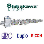
О ризографе
Разработчиком ризографа является компания Riso, которая известная с далеких времен как производитель краски для печати, в дальнейшем, занялась наладкой производства машин трафаретной печати и расходных материалов для них. Таким образом появился новый
О ризографе
-
04.09.2018
Error Codes list of Riso RZ370 model and quick guides
– Compatible Printer model: Riso RZ370
– Riso RZ370 Error Codes with quick guides:
- Code: A01
- Description: Master feed error
- Causes: 201 Master-positioning sensor does not go ON even after the write pulse motor is activated during the master-positioning, master-cut, or master-loading operation. 202 Master-positioning sensor does not go OFF even when the write pulse motor is reversed during the master-positioning or at start of master-making operation. 211 Master-positioning sensor is ON during standby. 214 Master-positioning sensor is ON at the start of master making. 215 Faulty gate-array control for the write pulse motor (motor does not stop within set time).
- Troubleshooting Guides: Open the master-making unit and rewind the master material on the master roll, and then reset the master, or turn OFF the power and power back ON.
- Code: A02
- Description: Master loading error
- Causes: 509 Master-loading sensor was OFF when the master was checked at a specified drum angle during the master-loading operation.
- Troubleshooting Guides: Pull out the print cylinder and set it back.
- Code: A04
- Description: Master disposal error
- Causes: 303 Check Print Drum – Master disposal error / Master disposal jam.
- Troubleshooting Guides: Pull out the print drum and push it back in.
- Code: A05
- Description: Master present in the master disposal area
- Causes: 304 Master disposal jam sensor was ON at the completion of the master disposal. 312 Master disposal jam sensor was ON at the start of the master making. 315 Master disposal jam sensor was ON after the completion of the recovery movement.
- Troubleshooting Guides: Pull out master disposal box and place it back after removing the jammed master in the master disposal area, or turn OFF the power and power back ON.
- Code: A06
- Description: Check paper feed tray
- Causes: 403 Either the upper or lower safety switch of the paper-feed-tray is OFF. Note: This detection is not made when the machine is in low-power-mode (24V OFF).
- Troubleshooting Guides: Change the condition of the paper-feed-tray upper/lower safety switches to ON condition, or turn OFF the power and power back ON.
- Code: A07
- Description: Paper feed error
- Causes: 409 Paper-ejection sensor was OFF when the paper should have arrived, and the paper sensor was ON when the machine stopped (Paper misfeed). 412 Paper sensor was OFF three times in succession when a paper misfeed was detected (paper misfeed). 413 Paper sensor was still ON (detecting paper) when the paper should have went out from the sensor. 418 The paper sensor was ON at the start of machine operation when the START button was pressed. 429 Paper feed error (recovery error). 432 Paper sensor was ON when the machine went into paper feed retry movement after a paper misfeed.
- Troubleshooting Guides:
- Code: A08
- Description: Paper jam on print drum
- Causes: 410 Paper-ejection sensor was OFF when paper should have arrived, and the paper sensor was OFF when the machine stopped (paper jam on the print drum). 430 Paper jam on print drum (recovery error).
- Troubleshooting Guides:
- Code: A09
- Description: Paper ejection error
- Causes: 411 Paper-ejection sensor was ON when the paper should have left the paper-ejection sensor. 417 Paper-ejection sensor was ON at the start of machine operation when the START button was pressed. 431 Paper-ejection error (recovery error).
- Troubleshooting Guides:
- Code: A10
- Description: AF original feed error
- Causes: 102 The original is pulled out from the AF unit before the scanning is completed. 103 Original jammed under AF registration sensor. 103 Original jam at AF registration sensor. Simplex AF: Registration-sensor does not go OFF after Original-IN-sensor goes ON. Duplex AF: Registration-sensor does not go OFF after the original feeds. 105 Original jammed at AF Read sensor. 106 Original jammed at original ejection sensor. 106 Original jam at AF original out sensor. Simplex AF: Original-OUT-sensor does not go OFF after Original-IN-sensor goes OFF. Duplex AF: Original-OUT-sensor does not go OFF after Registration-sensor goes OFF. 107 Original does not arrive to the AF Registration sensor. 108 Original does not arrive to the AF Read sensor. 109 Original does not arrive to the original ejection sensor. 109 Original Jam before AF original out sensor. Simplex AF: Original-OUT-sensor does not go ON after Original-IN-sensor goes ON. Duplex AF: Original-OUT-sensor does not go ON after the original feeds. 169 AF feed cover is opened due to original jam, while originals are present on the tray. 178 Original Jam before Original reverse sensor. Duplex AF: Original reverse sensor does not go ON after the original feeds. 179 Original Jam at Original reverse sensor. Duplex AF: Original reverse sensor does not go OFF after the original feeds. 180 Duplex AF: Original multiple feed
- Troubleshooting Guides:
- Code: A16
- Description: Waiting for the master to be removed from the drum
- Causes: 525 Waiting for the master to be removed from the print cylinder (drum).
- Troubleshooting Guides: Pull out the print cylinder (drum), remove the master around it and insert it back.
- Code: A17
- Description: Cutter error
- Causes: 209 Cutter HP switch is OFF when master-making starts, when the master material is set in the master making unit, or when the machine goes into idle condition.
- Troubleshooting Guides: Open the Master making unit, remove the master and close the master making unit.
- Code: A34
- Description: Requesting for the master to be reset
- Causes: 218 Reqesting for the master material to be reset into the master making unit.
- Troubleshooting Guides: Open the Master making unit, re-insert the master material into the master making unit.

- Code: B01
- Description: Keycard counter: No card
- Causes: 730 Keycard counter: No card O O
- Troubleshooting Guides: Insert card.
- Code: B02
- Description: Sorter error – Serviceman Call
- Causes: 702 Serviceman call error command was received from the sorter.
- Troubleshooting Guides: Check the sorter.
- Code: B03
- Description: Sorter error – Jam
- Causes: 703 Received paper jam error command was received from the sorter.
- Troubleshooting Guides: Remove the jammed paper.
- Code: B04
- Description: Sorter error – Door open
- Causes: 707 Cover open error cmmand was received from the sorter.
- Troubleshooting Guides: Close the sorter cover.
- Code: B05
- Description: Soter Error – Other errors
- Causes: 709 Other error command was received from the sorter.
- Troubleshooting Guides: Check the sorter.
- Code: B07
- Description: MTPF – Paper Jam (upper)
- Causes: 825 Received paper jam error from the MTPF unit. The FL feed sensor 4 does not go ON after the Transfer motor activated for set pulses from the moment the FL feed sensor 3 turned ON.(FL feed sensors 1 & 2 = OFF, sensor 3=ON). Or the FL feed sensor 3 is ON when the machine power is turned ON. 826 Received paper jam error from the MTPF unit. After the paper is fed, the FL feed sensor 4 goes ON, but the Paper sensor does not go ON even after the FL transfer motor activated for the set pulses.(FL feed sensors 1 &2 = OFF, sensors 3 & 4 =ON). Or the FL feed sensors 3 & 4 are ON when the machine power is turned ON. 827 Received paper jam error from the MTPF unit. While the machine is in idle state (waiting for a print job), the FL feed sensors 3 & 4 and Paper sensor are ON. 828 After the paper is fed, the FL feed sensor 4 goes ON, but the Paper sensor does not go ON even after the FL transfer motor activated for the set pulses.(FL feed sensors 1, 2 & 3 = OFF, sensor 4 =ON). Or the FL feed sensor 4 is ON when the machine power is turned ON. 829 Received paper jam error from the MTPF unit. While the machine is in idle state (waiting for a print job), the FL feed sensor 4 and Paper sensor are ON. 849 MTPF other jam errors. 850 MTPF Tray No.1 multiple feed error. 851 MTPF Tray No.2 multiple feed error. 852 MTPF Tray No.1 multi-drag feed error 1 (wrong A/D data) 853 MTPF Tray No.2 multi-drag feed error 1 (wrong A/D data) 856 MTPF Tray No.1 multi-drag feed error 1 (FL feed sensor 4 does not go OFF) 857 MTPF Tray No.2 multi-drag feed error 1 (FL feed sensor 4 does not go OFF)
- Troubleshooting Guides: Remove the jammed paper.
- Code: B08
- Description: MTPF – Feed Joint Passage Cover Open Error
- Causes: 805 Feed joint passage cover open error singal is received from MTPF unit.
- Troubleshooting Guides: Close the feed joint passage cover.
- Code: B09
- Description: MTPF – Paper Jam (lower)
- Causes: 816 Received paper jam error from the MTPF unit. After the paper is fed, the FL feed sensor 1 goes ON, but the FL feed sensor 2 does not go ON even after the FL transfer motor activated for the set pulses. (FL feed sensors 1 = ON). Or the FL feed sensor 1 is ON w hen the machine power is turned ON. 817 Received paper jam error from the MTPF unit. After the paper is fed, the FL feed sensor 2 goes ON, but the FL feed sensor 3 does not go ON even after the FL transfer motor activated for the set pulses. (FL feed sensors 1 & 2 = ON). Or the FL feed sensors 1 & 2 are ON when the machine power is turned ON. 818 Received paper jam error from the MTPF unit. After the paper is fed, the FL feed sensor 3 goes ON, but the FL feed sensor 4 does not go ON even after the FL transfer motor activated for the set pulses. (FL feed sensors 1, 2 & 3 = ON). Or the FL feed sensors 1, 2 & 3 are ON when the machine power is turned ON. 819 Received paper jam error from the MTPF unit. After the paper is fed, the FL feed sensor 4 goes ON, but the Paper sensor does not go ON even after the FL transfer motor activated for the set pulses. (FL feed sensors 1, 2, 3 & 4 = ON). Or the FL feed sensors 1, 2, 3 & 4 are ON when the machine power is turned ON. 820 Received paper jam error from the MTPF unit. While the machine is in idle state (waiting for a print job), the FL feed sensors 1, 2, 3 & 4 and Paper sensor are ON. 821 Received paper jam error from the MTPF unit. After the paper is fed, the FL feed sensor 2 goes ON, but the FL feed sensor 3 does not go ON even after the FL transfer motor activated for the set pulses. (FL feed sensor 1 = OFF, sensor 2 = ON). Or the FL feed sensor 2 is ON w hen the machine power is turned ON. 822 Received paper jam error from the MTPF unit. After the paper is fed, the FL feed sensor 3 goes ON, but the FL feed sensor 4 does not go ON even after the FL transfer motor activated for the set pulses. (FL feed sensor 1 = OFF, sensors 2 & 3 = ON). Or the FL feed sensors 2 & 3 are ON when the machine power is turned ON. 823 Received paper jam error from the MTPF unit. After the paper is fed, the FL feed sensor 4 goes ON, but the Paper sensor does not go ON even after the FL transfer motor activated for the set pulses. (FL feed sensor 1 = OFF, sensors 2, 3 & 4 = ON). Or the FL feed sensors 2, 3 & 4 are ON when the machine power is turned ON. 824 Received paper jam error from the MTPF unit. While the machine is in idle condition (waiting for a print job), the FL feed sensors 2, 3 & 4 and Paper sensor are ON. 825 Received paper jam error from the MTPF unit. After the paper is fed, the FL feed sensor 3 goes ON, but the FL sensor 4 does not go ON even after the FL transfer motor activated for the set pulses. (FL feed sensors 1 & 2 = OFF, sensor 3 = ON). Or the FL feed sensor 3 is ON w hen the machine power is turned ON. 849 MTPF other jam errors. 854 MPTF Tray No.1 Multi-drag feed error 2 (FL feed sensor 3 does not go OFF) 855 MPTF Tray No.2 Multi-drag feed error 2 (FL feed sensor 3 does not go OFF)
- Troubleshooting Guides: Remove the jammed paper.
- Code: B11
- Description: MTPF – Tray No.1 Paper Jam
- Causes: 807 Received paper jam error from MTPF unit. Paper misfeed from Tray No.1 (FL feed sensor 3 = OFF) 842 The Paper sensor is still OFF w hen the paper from Tray No.1 should have arrived at the sensor. 858 The mult-tray 1 pickup sensor is ON at the start of a printing job from Tray No.1. * If any of the FL feed sensor is ON at the same time, the error message on those sensors w ill be displayed.
- Troubleshooting Guides: Remove the jammed paper and reset Tray No.1 in MTPF Unit.
- Code: B13
- Description: MTPF – Tray No.1 Open Error
- Causes: 809 MTPF Tray No.1 is opened.
- Troubleshooting Guides: Set the Tray No.1 back in place.
- Code: B15
- Description: MTPF – FL Transfer Unit Door Open Error
- Causes: 800 The MTPF Transfer unit is opened.
- Troubleshooting Guides: Close the MTPF Transfer unit.
- Code: B17
- Description: MTPF – Tray No.2 Paper Jam
- Causes: 812 Received paper jam error command from MTPF unit. Paper misfeed from Tray No.2 (FL feed sensor 1 = OFF) 843 The Paper sensor is still OFF when the paper from Tray No.2 should have arrived at the sensor.
- Troubleshooting Guides: Remove the jammed paper and reset Tray No.2 in MTPF Unit.
- Code: B19
- Description: MTPF – Tray No.2 Open Error
- Causes: 814 MTPF Tray No.2 is opened.
- Troubleshooting Guides: Set the Tray No.2 back in place.
- Code: B21
- Description: Hold Memory – Unable to Read or Write
- Causes: 714 File name error on the Hold Memory. 715 Access error on the Hold Memory. 716 Other error on the Hold Memory.
- Troubleshooting Guides: Switch OFF the power and then switch ON the power back.
- Code: B22
- Description: Job separator: Power off
- Causes: 721 With the [Tape separation] function set ON, no power is supplied to the job separator when start key is pressed. 727 After cluster-A signal turned ON, BUSY-signal stayed [L] more than 7 seconds (power to job separator was turned OFF while the tape is being ejected.
- Troubleshooting Guides: Press Reset Key and check and switch ON the power of Job Separator.
- Code: B23
- Description: Job separator: No tape
- Causes: 722 With the [Tape separation] function set ON, no tape detected in the job separator when the start key is pressed. 723 No tape remains in job separator upon completion of the tape-ejection operation.
- Troubleshooting Guides: Press Reset Key and set paper tape in Job Separator.
- Code: B24
- Description: Job separator: Tape jam
- Causes: 724 Tape jam detected when the start key is pressed with the [Tape separation] function set to ON. 725 The tape-jam detection signal is [H] for more than 1.2 seconds after cluster-A signal turns ON (tape misfeed). 726 Job separator tape-jam detection signal is [L] when the BUSY signal changes from [L] to [H] (or after 7 sec. at [L]) after the cluster-A signal goes ON (tape misfeed).
- Troubleshooting Guides: Press Reset Key and remove the jammed tape.
- Code: B25
- Description: Sorter – Tray Full Error
- Causes: 704 Sorter tray full.
- Troubleshooting Guides: Remove papers from the sorter tray.
- Code: B26
- Description: Sorter – Paper Remaining on the Tray
- Causes: 705 Paper remaining on the sorter tray.
- Troubleshooting Guides: Remove paper from the sorter tray.
- Code: B27
- Description: Sorter – Stapler Error
- Causes: 706 Stapler error command is received from the sorter.
- Troubleshooting Guides: Check the stapler and correct the stapler problem.
- Code: B28
- Description: Sorter – paper Size Error
- Causes: 708 Paper size error command was received from the Sorter.
- Troubleshooting Guides: Remove paper from the sorter tray.
- Code: B31
- Description: Network cable not connected
- Causes: 916 Network cable is not connected when the machine is powered ON.
- Troubleshooting Guides: Press Reset Key and connect the network cable.
- Code: B32
- Description: NIC – Communication error
- Causes: 914 MIB (Management Informtion Base) request error 915 MIB no reply 917 Communication error on the network. 920 Error detected by Network Interface Card (NIC) – NAK (negative acknowledgement was received).
- Troubleshooting Guides: Press Reset Key, and check the network cable and linked printer.
- Code: B33
- Description: IP address set up error
- Causes: 931 DHCP is ON, but DHCP server is not found.
- Troubleshooting Guides: Press Reset Key, and enter the IP address.
- Code: B34
- Description: Linked Printer Error (RZ3) [Linked Printer – No Toner Error] (RZ5 & RZ9)
- Causes: 919 Error on the linked printer. 919 No toner in the linked printer.
- Troubleshooting Guides: Press [Reset] Key and correct the error on the linked printer (RZ3). Press [Reset] Key and replace the toner on the linked printer (RZ5 & RZ9).
- Code: B35
- Description: Linked Printer: Call Service Error
- Causes: 970 Error in the linked printer.
- Troubleshooting Guides: Press Reset Key, and correct the error on the linked printer.
- Code: C01
- Description: Replace ink cartridge
- Causes: 512 The ink sensor did not go ON even when inking was performed for a preset duration. 563 Ink remaining amount is zero from the information on the RF-Tag. 574 Inkless error was detected 5 times consecutively on one same ink cartridge.
- Troubleshooting Guides: Remove the empty ink cartridge and replace with a new one.
- Code: C02
- Description: Replace master roll
- Causes: 200 The master end was detected twice in succession at 10-milliseconds intervals during master transport. 240 Master remaining amount is zero from the RF-Tag information. 253 Masterless error was detected twice consecutively on one same master-roll.
- Troubleshooting Guides: Remove the empty master roll and replace with a new one.
- Code: C03
- Description: Master disposal box full
- Causes: 308 Compression detection position was reached before the master-compression-motor encoder-sensor count reached the specified level, after the master compression motor turned ON in the compressing direction.
- Troubleshooting Guides: Remove master disposal box from the machine, throw away the disposed master from the disposal box and return the disposal box in the machine after an interval of over 5 seconds.
- Code: C04
- Description: No paper on the Standard paper Feed Tray
- Causes: 402 Paper detection sensor is OFF (not detecting paper).
- Troubleshooting Guides: Add paper on the standard paper feed tray.
- Code: C06
- Description: MTPF – No Paper in Tray No.1
- Causes: 859 No paper in Tray No.1
- Troubleshooting Guides: Fill Tray No.1 with paper.
- Code: C07
- Description: MTPF – No Paper in Tray No.2
- Causes: 860 No paper in Tray No.2 x x
- Troubleshooting Guides: Fill Tray No.2 with paper.
- Code: C08
- Description: No Interposal Paper on Standard Paper Feed Tray
- Causes: 861 No paper is set on the standard paper feed tray while the tray is specified as interposer tray by the Admin. Tab on the operation panel.
- Troubleshooting Guides: Press [Reset] key, and load interposal paper on the standard paper feed tray.
- Code: C09
- Description: No Interposal Paper in MTPF Tray No.1
- Causes: 862 No paper is set in Tray No.1 while the tray is specified as interposer tray by the Admin. Tab on the operation panel.
- Troubleshooting Guides: Press [Reset] Key and load interposal paper in Tray No.1
- Code: C10
- Description: No Interposal Paper in MTPF Tray No.2
- Causes: 863 No paper is set in Tray No.2 while the tray is specified as interposer tray by the Admin. Tab on the operation panel.
- Troubleshooting Guides: Press [Reset] Key and load interposal paper in Tray No.2
- Code: D01
- Description: Print drum not set
- Causes: 526 Print drum is not set in the machine (drum connection signal, drum safety switch, and drum-lock sensor is OFF. 527 Print drum connection signal is OFF when the print drum was inserted in the machine. 528 Print drum safety switch is OFF when the print drum was inserted in the machine. 529 Print drum lock sensor is OFF when the print drum was inserted in the machine (time-out: 5 seconds). 530 Print drum connection signal does not go OFF within 5 seconds after the print drum safety switch went OFF when the print drum was pulled out.
- Troubleshooting Guides: Set the print drum in the machine.
- Code: D02
- Description: Incorrect print drum
- Causes: 532 Incorrect print drum is used. 580 Incorrect print drum is used.
- Troubleshooting Guides: Set correct print drum in the machine.
- Code: D03
- Description: Ink cartridge not set
- Causes: 533 Bottle set switch is OFF.
- Troubleshooting Guides: Install ink cartridge in the print drum.
- Code: D04
- Description: Incorrect ink cartridge
- Causes: 534 Incorrect ink cartridge is used. 560 Ink RF-Tag is not detected on ink bottle. 561 Ink RF-Tag communication error (communication with the ink cartridge was interfered by noise). 562 Wrong ink cartridge information on the Ink RF-Tag. 564 Detected a mismatch in the Ink RF-Tag. 575 RF-Tag software error.
- Troubleshooting Guides: Replace with correct ink cartridge.
- Code: D05
- Description: Master not set
- Causes: 210 Master detection sensor is OFF (not detecting master material).
- Troubleshooting Guides: Insert leading edge of the master material into the master entrance and close the master making unit.
- Code: D07
- Description: Master disposal box not set
- Causes: 310 Master disposal box safety switch is OFF. (Does not detect the error during low-power mode in which 24V power is down)
- Troubleshooting Guides: Set master disposal box in the machine.
- Code: D08
- Description: Master making unit not set
- Causes: 224 Master making unit is not set (both the safety switch and lock sensor are OFF). 226 Master making unit safety switch is still OFF when the master making unit is set in position. 227 Master making unit lock sensor is still OFF when the master making unit is set in position (timeout: 5 seconds). 228 Master making unit lock sensor is still ON even after the master making unit safety switch went OFF, when the master making unit was pulled out of the machine.
- Troubleshooting Guides: Insert the master making unit in the machine.
- Code: D09
- Description: Master making unit cover is not closed
- Causes: 212 Master making unit cover set sensor is OFF.
- Troubleshooting Guides: Close the master making unit cover.
- Code: D11
- Description: Front cover not closed
- Causes: 535 Front cover set sensor is OFF.
- Troubleshooting Guides: Close the front cover of the machine.
- Code: D13
- Description: Rear cover not closed
- Causes: 009 The rear cover is opened (serviceman safety switch is OFF).
- Troubleshooting Guides: Close the rear cover of the machine to activate the rear cover (serviceman safety) switch. [Field serviceman has to close and screw-on the rear cover]
- Code: D17
- Description: Incorrect master roll
- Causes: 236 Incorrect master roll. 237 Master roll RF-Tag not detected. 238 Master roll RF-Tag communication error. (Communication interrupted by noise) 239 Incorrect information on the Master roll RF-Tag. 241 Mismatch in the Master roll RF-Tag information. 256 Master roll RF-Tag software error.
- Troubleshooting Guides: Set correct master roll in the machine.
- Code: D18
- Description: Print cylinder (drum) is ready for removal
- Causes: 522 Print Cylinder (Drum) is unlocked for its removal. (Drum lock Solenoid is ON).
- Troubleshooting Guides: Pull out the print Cylinder (Drum).
- Code: D19
- Description: Master making unit is ready for removal
- Causes: 223 Master making unit is unlocked for its removal. (Lock Solenoid is ON).
- Troubleshooting Guides: Pull out the master making unit.
- Code: D22
- Description: Print cylinder (drum) removal command
- Causes: 540 Cannot access to the EEPROM on the print drum PCB. 542 Print drum PCB EEPROM data error.
- Troubleshooting Guides: Pull out print cylinder (drum) from the machine.
- Code: D32
- Description: AF Cover Not Closed
- Causes: 177 The AF cover is opened.
- Troubleshooting Guides: Close the AF cover.
- Code: E01
- Description: Replace battery
- Causes: 010 Battery voltage was less than 2.1 V when the power was switched ON (weak battery: time to replace battery).
- Troubleshooting Guides: Press Reset Key, and replace the battery.
- Code: E02
- Description: Maintenance call
- Causes: 011 Master counter reached the value set for the maintenance call (value set by test mode). [The message appears when either the power is turned ON, the unit is reset, or when the machine operation ended.] 012 Copy counter reached the value set for the maintenance call (value by set test mode). [The message appears when either the power is turned ON, the unit is reset, or when the machine operation ended.] 022 Maintenance counter inside the print drum reached the value set for the maintenance call (value set by test mode). [The message appears when either the power is turned ON, the unit is reset, or when the machine operation ended.]
- Troubleshooting Guides: Press Reset Key, and also reset the maintenance call value setting by test mode.
- Code: F01
- Description: No master on print cylinder (drum)
- Causes: 015 There is no master on the print drum at the start of printing.
- Troubleshooting Guides: Make a new master with an original.
- Code: F02
- Description: Master image larger than paper size: 1
- Causes: 018 Paper size does not match with the image size on the print drum at the start of printing. The paper size is smaller than the image size on the master.
- Troubleshooting Guides: Press [OK] or [Cancel] button. Also check the paper size.
- Code: F03
- Description: Multi-up printing – Incorrect paper size
- Causes: 016 Tried to make multi-up printing with incorrect paper size.
- Troubleshooting Guides: Press reset key and place correct size papers on the paper feed tray.
- Code: F05
- Description: Print quantiy under Minimum Print Quantity
- Causes: 019 In master making, the print quantity selected is less than the minimum print quantity.
- Troubleshooting Guides: Enter print quantity value over the programmed minimum value.
- Code: F08
- Description: Auto Tray – Paper Size and Original Size does not Match
- Causes: 017 When the Auto-Tray is selected, the original size (scanning ratio) and the printing paper set on the tray(s) did not match.
- Troubleshooting Guides: Press CANCEL button, and check the paper and original size.
- Code: F10
- Description: Master image larger than paper size: 2
- Causes: 021 Paper size does not match with the size of image on the print drum when test print is selected and activated.
- Troubleshooting Guides: Press Cancel key to cancel, or press Proof key to continue.
- Code: F12
- Description: Auto-Tray: Irregular Size Original
- Causes: 024 Irregular size original was used when Auto-Tray was selected.
- Troubleshooting Guides: Press [CANCEL] key
- Code: F15
- Description: Paper size does not match with the paper on the paper receiving tray
- Causes: 042 With the auto-control-paper-receving-tray connected, the paper on the receiving tray is larger than the printing paper.
- Troubleshooting Guides: Press [CANCEL] button
- Code: F17
- Description: Print cylinder (drum) size does not match
- Causes: 027 Different size print cylinder (drum) from the previous is set.
- Troubleshooting Guides: Select the same drum as specified, or install the same drum installed previously.
- Code: F18
- Description: Paper Size and Original Size Do Not Match
- Causes: 875 The paper size and the original size (reproduction ratio) does not match in mastermaking. (The error message is for machines with MTPF unit and when Auto-Tray is selected.
- Troubleshooting Guides: Press either the START or STOP key.
- Code: F21
- Description: Next Original not set on AF for Multi-Up
- Causes: 032 Next original is not set on AF whe multi-up is selected.
- Troubleshooting Guides: Set original on the AF. Or press STOP key (time-out exists for pressing the STOP key).
- Code: F22
- Description: Next Original not placed on FB for Multi-Up
- Causes: 033 Next Original not placed on FB for Multi-Up scanning.
- Troubleshooting Guides: Set origial on the FB and press START key. Or press STOP key (Time-out exists for pressing the STOP key)
- Code: F24
- Description: Auto Reproduction Size Selection Not Possible
- Causes: 037 The reproduction ratio does not match.
- Troubleshooting Guides: Press [STOP] key
- Code: F30
- Description: Possible Multiple Paper Feed
- Causes: 425 Multiple paper feed is detected on the first paper fed through. 426 Multiple paper feed is detected on the paper just fed through. (Other than the 1st paper.)
- Troubleshooting Guides: Press [STOP] key
- Code: F31
- Description: Auto Control Paper Receiving Tray – Paper Guide Fence Error
- Causes: 836 HP sensor did not go ON when the side fences made initial home position movement. 837 HP sensor did not go OFF when the side fences should have left home position. 838 HP sensor did not go ON when the end fence made initial home position movement. 839 HP sensor did not go OFF when the end fence should have left home position. 868 Even though the End fence pulse motor ended its movement by the sensor detection, the sensor status does not match with the programmed status. 869 Even though the Side fence pulse motor ended its movement by the sensor detection, the sensor status does not match with the programmed status. 870 The End fence pulse motor does not stop either by its pulse count stop nor by sensor detected stop. 871 The Side fence pulse motor does not stop either by its pulse count stop nor by sensor detected stop.
- Troubleshooting Guides: Press either the {START] or [STOP] key.
- Code: F32
- Description: Storage Data – Storage Area Full
- Causes: 713 The DM-128 card became full while saving data.
- Troubleshooting Guides: Press [STOP] key
- Code: F37
- Description: Book mode: AF cannot be used
- Causes: 050 Original was set on the AF with book mode selected in master making.
- Troubleshooting Guides: Place original on the stage glass.
- Code: F40
- Description: Auto Tray Selection – No Paper on Standard Paper Feed Tray
- Causes: 060 The paper ran out from the standard paper feed tray, when printing from the standard paper feed tray using the Auto tray selection with Feed-tray-relay activated. (Other trays also paper empty.) 907 The paper ran out from the standard paper feed tray, when printing from the standard paper feed tray using the Auto tray selection with Feed-tray-relay OFF.
- Troubleshooting Guides: Load paper on the standard paper feed tray.
- Code: F41
- Description: Auto Tray Selection – No Paper in Tray-1
- Causes: 061 The paper ran out from MTPF Tray No.1, when printing from the Tray No.1 using the Auto tray selection with Feed-tray-relay activated. (Other trays also paper empty.) 908 The paper ran out from MTPF Tray No.1, when printing from Tray No.1 using the Auto tray selection with Feed-tray-relay OFF.
- Troubleshooting Guides: Load paper in MTPF Tray No.1.
- Code: F42
- Description: Auto Tray Selection – No Paper in Tray-2
- Causes: 062 The paper ran out from MTPF Tray No.2, when printing from the Tray No.2 using the Auto tray selection with Feed-tray-relay activated. (Other trays also paper empty.) 909 The paper ran out from MTPF Tray No.2, when printing from Tray No.2 using the Auto tray selection with Feed-tray-relay OFF.
- Troubleshooting Guides: Load paper in MTPF Tray No.2.
- Code: F43
- Description: Data printing / Paper size mismatch
- Causes: 902 Original size is larger than the paper size.
- Troubleshooting Guides: Check paper size, press Cancel or Continue key.
- Code: F44
- Description: Auto Reproduction Size – Error Between Original Size and Paper Size
- Causes: 901 Original size could not be detected (original size out of the specification).
- Troubleshooting Guides: Press [CANCEL] button.
- Code: F45
- Description: Original Undetected
- Causes: 954 Auto-tray or Auto-reproduction size is selected, and master making or print to linked printer is started with original undetected 959 Master making or print to a linked printer is started with original undetected. 981 The original not detected when [NEXT] button was pressed in Multi-Up Wizard display.
- Troubleshooting Guides: Reset the original in place.
- Code: F47
- Description: AF – card size reproduction not available
- Causes: 904 Reproduction size from A4 size reduced to card size is selected and the original is placed on the AF unit.
- Troubleshooting Guides: Remove original from AF and set it on the stage glass.
- Code: F48
- Description: Multi-Up – Wrong Original Size
- Causes: 955 During the multi-up operation, the original size was detected as customs size or out of specification.
- Troubleshooting Guides: Press [STOP] key.
- Code: F49
- Description: Multi-Up – No Original
- Causes: 989 The original was undetected when Multi-Up operation was selected for either one original or multi-original.
- Troubleshooting Guides: Press [STOP] key
- Code: F52
- Description: Printing from Linked Printer disabled – Printer data not received
- Causes: 912 Printing from linked printer disabled (Linked printer data not received).
- Troubleshooting Guides: Press the [CLOSE] button.
- Code: F58
- Description: Printing from Linked Printer Disabled – Initializing NET-C
- Causes: 927 Printing from Linked Printer disabled (NET-C/D being initialized).
- Troubleshooting Guides: Press the [CLOSE] button.
- Code: F60
- Description: [Printer-Auto-Selection disabled: Print quantity selected is 0
- Causes: 929 Auto-printer-selection is disabled with print quantity selected as Zero.
- Troubleshooting Guides: Press either [OK] or [Cancel] button.
- Code: F61
- Description: Linked Printer – Wrong Paper Size
- Causes: 930 Original size does not match with the paper size set on the linked printer.
- Troubleshooting Guides: Press [CANCEL] button.
- Code: F62
- Description: Printer-Auto-Selection disabled – Linked printer error
- Causes: 956 Auto-printer-selection is disabled due to linked printer error.
- Troubleshooting Guides: Press [Cancel] button.
- Code: F63
- Description: Linked Printer – Auto Tray Selection not avaialble for Irregular Size Original
- Causes: 971 Auto-Tray-Selection was used in printing from the linked printer using irregular sized original.
- Troubleshooting Guides: Press [CANCEL] button
- Code: F64
- Description: Selected Function Not Available While Processing Print Data from PC
- Causes: 964 Scanning, Overlay, Digitizer or Hold function was selected while the printer is receving data from PC.
- Troubleshooting Guides: Press {CLOSE] button.
- Code: F65
- Description: Scan Mode – Auto Page Size Selection Not Available for Irregular Size Original
- Causes: 965 The auto-size (save data) selection at start of scanning is detected as original irregular in size.
- Troubleshooting Guides: Press [RESET] key.
- Code: F66
- Description: Linked printer saddle stitching is disabled
- Causes: 962 Specified tray does not have any A3 (Ledger), B4 (Legal), A4 (Letter) or A4L (Letter-L) when printing from linked printer with saddle stitching selected.
- Troubleshooting Guides: Press [Close] button.
- Code: F67
- Description: Linked printer saddle stitching is disabled
- Causes: 963 Specified size papers are not set in horizontal and vertical directions in the linked printer tray, when printing from linked printer with rotation sorting selected.
- Troubleshooting Guides: Press [Close] button.
- Code: F73
- Description: Linked Printer – Auto Tray Selection Not Available with Selected Reproduction Ratio
- Causes: 975 In Linked Printer printing, the detected original size does not match with the selected reproduction size.
- Troubleshooting Guides: Press [STOP] key.
- Code: F74
- Description: High Speed Printing – Printer Temperature is Too Low for 180 ppm High Speed Printing
- Causes: 980 High speed printing was selected with the machine temperature below 15 degrees Celcius.
- Troubleshooting Guides: Press [STOP] or [START] key.
- Code: F78
- Description: Editor – Stage Cover is Opened
- Causes: 731 The stage cover is opened during the digitizer operation.
- Troubleshooting Guides: Close the stage cover and press [CLOSE] button.
- Code: F79
- Description: Editor – No Original During Re-Scanning
- Causes: 732 The original was not detected during re-scanning.
- Troubleshooting Guides: Press [STOP] key
- Code: F85
- Description: External CI – Scanning Not Possible with External CI not Connected
- Causes: 995 Either the PS7R is not connected or improperly connect.
- Troubleshooting Guides: Press [CLOSE] button or press [START] key.
- Code: F86
- Description: Auto Tray Selection – Tray Cannot Be Selected with Selected Reproduction Ratio
- Causes: 864 With the Auto Tray selected, the master-making was activated with original size which does not match with the reproduction ratio against the printing paper.
- Troubleshooting Guides: Press [STOP] Key
- Code: F87
- Description: Auto Tray Selection – Mult-Up Not Possible
- Causes: 865 Multi-Up was chosen with Auto Tray selected.
- Troubleshooting Guides: Press [ENTER] button or [CANCEL] button.
- Code: F88
- Description: Auto Tray Selection – 2 UP Selection Error
- Causes: 866 With Auto Tray selected, the 2-UP was selected with printing papers other than A4R or B5R.
- Troubleshooting Guides: Press [STOP] key
- Code: F89
- Description: Interposer Mode – Wrong Paper Size
- Causes: 867 Interposer mode was selected with interposal paper smaller than the printing paper.
- Troubleshooting Guides: Press [STOP] key.
- Code: F90
- Description: Ink Supply Stock Inventory
- Causes: 957 Set quantity of the specified color ink stock quantity is equal to or less than the calculated stock quantity.
- Troubleshooting Guides: Press [CLOSE] button.
- Code: F91
- Description: Master Roll Supply Stock Inventory
- Causes: 958 Set quantity of the specified master roll stock quantity is equal to or less than the calculated stock quantity.
- Troubleshooting Guides: Press [CLOSE] button.
- Code: F92
- Description: Original Size – Larger than the Master Making Size
- Causes: 874 Master making was selected with an original larger in size than the paper size when Auto Tray selection is made and reproduction ratio at 100%. (The error message appears only on the machines with MTPF unit and Auto Tray selected.)
- Troubleshooting Guides: Press [START] key, or [STOP] key.
- Code: F93
- Description: Reproduction Size – Larger than the Master Making Size
- Causes: 936 Either of the following two causes the reproduction ratio to exceed the printing area. 1) Auto Tray is selected with reproduction ratio neither at 100% nor at AUTO. 2) Paper tray is manually selected and the reproduction ratio is at AUTO.
- Troubleshooting Guides: Press [START] key, or press [STOP] key.
- Code: F94
- Description: Protect Mode – Discard Current Master
- Causes: 007 The protect function is active when machine power is turn ON, machine woke up from sleep, or print drum is inserted into the machine.
- Troubleshooting Guides: Press [START] key.
- Code: F95
- Description: Protect Mode – Confirmation
- Causes: 008 The job completes when the protect mode is selected active by the Admin. display.
- Troubleshooting Guides: Press [START] key, or press [STOP] key.
- Code: H1
- Description: Ink color setting
- Causes: H1 Select the same color as the Print Cylinder (Drum) currently in use.
- Troubleshooting Guides: Enter the required parameter value.
- Code: H2
- Description: Print density fine adjustment
- Causes: H2 Select a Print Density level to match the ink to fine-tune print result.
- Troubleshooting Guides: Enter the required parameter value.
- Code: H3
- Description: First print density adjustment
- Causes: H3 Select a Print Density level of the first print (proof-read copy) to match the ink.
- Troubleshooting Guides: Enter the required parameter value.
- Code: H4
- Description: Master Density
- Causes: H4 Select the standard density to be applied during master-making.
- Troubleshooting Guides: Enter the required parameter value.
- Code: H5
- Description: Print density fine adjustment
- Causes: H5 Select a Print Density level to match the master to fine-tune print result.
- Troubleshooting Guides: Enter the required parameter value.
- Code: H6
- Description: First print density adjustment
- Causes: H6 Select a Print Density level of the first print (proof-read copy) to match the master.
- Troubleshooting Guides: Enter the required parameter value.
- Code: T01
- Description: Main motor lock
- Causes: 520 Main encoder sensor does not go ON/OFF within 10 milliseconds after the main motor activates. 520 Main motor lock detection due to main motor FG sensor count reduced to 50% of the set speed. (The detection is not made for the first 2 seconds from the main motor movement.) 521 B-positioning sensor status does not change even after 3,033 pulses after the main motor activates. 524 Clamp unit is not at the home position while the print drum is in operation (except during master disposal). 537 Print drum failed to stop at position B. 538 Print drum is not locked during operation. (Drum lock sensor: OFF)
- Troubleshooting Guides: Press Reset Key
- Code: T02
- Description: Elevator motor lock
- Causes: 400 Both the upper and lower limit sensors are ON at the same time. 401 Overload current was detected in the elevator motor. 404 The lower-limit sensor does not go OFF within 2 seconds after the elevator motor operates in the raising direction from the lower-limit position. 405 The upper-limit sensor does not go ON within 12 seconds after the elevator motor operates in the raising direction. 406 The upper-limit sensor does not go OFF within 2 seconds after the elevator motor operates in the lower direction from the upper-limit position. 407 The lower-limit sensor does not go ON within 12 seconds after the elevator motor operates in the lowering direction. 408 The upper-limit sensor is OFF continuously for over 2 seconds during operation of the elevator servo action to raise the feed tray.
- Troubleshooting Guides: Press Reset Key or turn OFF and ON the power.
- Code: T03
- Description: Clamp motor lock
- Causes: 500 Clamp sensor A is OFF after the completion of the clamp unit initialization or home positioning movement. 501 Clamp sensor B does not change within 1 second from the time the clamp motor operates in the forward direction. 502 Clamp sensor B does not change within 1 second from the time the clamp motor operates in the reverse direction. 503 Clamp sensor A does not go ON within 3 seconds when the clamp unit makes initialization movement. 504 At the start of Clamp plate open/close action, the detection sequence of clamp-sensors A & B are abnormal. 505 At the start of print drum Position-A compensation movement, the detection sequence of clamp-sensors A & B are abnormal. 506 At the start of Clamp unit Home-positioning movement, the detection sequence of clampsensors A & B are abnormal. 507 Clamp sensor A is ON after the clamp release action is completed. 508 Clamp sensor A is ON after the A-position compensating movement is completed. 545 Clamp unit is not in the home position while the print drum is in movement (cause due to the clamp motor).
- Troubleshooting Guides: Press Reset Key
- Code: T04
- Description: Ink overflow
- Causes: 513 The overflow sensor is ON for a set number of times in succession during the 10- millisecond-interval overflow-sensor check.
- Troubleshooting Guides: Press Reset Key after correcting the ink overflow condition. (No ink on the ink overflow sensor.)
- Code: T05
- Description: Vertical print positioning pulse motor lock
- Causes: 603 The vertical-centering sensor does not switch ON even when the vertical-positioning pulse motor activated in the image-down direction for 5.0 seconds during vertical home positioning movement. 603 The vertical-centering sensor does not switch ON even when the vertical-positioning pulse motor activated in the image-down direction for 5.5 seconds during vertical home positioning movement. 603 The vertical-centering sensor does not switch ON even when the vertical-positioning pulse motor activated in the image-down direction for regulation time during vertical home positioning movement. 604 The vertical-centering sensor does not switch OFF even when the vertical-positioning pulse motor activated in the image-up direction for 5.0 seconds during vertical home positioning movement. 604 The vertical-centering sensor does not switch OFF even when the vertical-positioning pulse motor activated in the image-up direction for 5.5 seconds during vertical home positioning movement. 604 The vertical-centering sensor does not switch OFF even when the vertical-positioning pulse motor activated in the image-up direction for regulation time during vertical home positioning movement. 605 Even though the vertical positioning motor stopped according to the vertical centering sensor detection, the stopping position does not correspond with the programmed position. (GA control error). 612 The print positioning key is pressed with vertical-print-position information undefined. 619 The vertical positioning motor does not end its operation within the set period during the recovery movement to rotate -98 pulses. 632 The vertical positioning motor does not end its operation within the set period in the pulse count stop mode, or in the sensor stop mode after the actuator is detected by the sensor.
- Troubleshooting Guides: Press Reset Key or turn the power OFF and ON.
- Code: T06
- Description: Print drum horizontal pulse motor lock
- Causes: 607 The actuator plate does not escape from the horizontal HP sensor when the print drum slides to the right during the horizontal HP movement. 608 The actuator plate does not escape from the horizontal HP sensor when the print drum slides to the left during the horizontal HP movement. 609 Even though the horizontal positioning pulse motor stopped after the sensor stop mode, the sensor detection status did not match with the programmed status. 611 Timeout error during print drum horizontal movement. 617 Horizontal movement system information error. 618 The clamp unit is not in its HP position when the print drum starts its horizontal movement. 633 The horizontal positioning pulse motor does not end its operation within the set period in the pulse count stop mode, or in the sensor stop mode after the actuator is detected by the sensor.
- Troubleshooting Guides: Press Reset Key or turn the power OFF and ON.
- Code: T08
- Description: Communication error with CI
- Causes: 951 The file is not a correct RINC data.
- Troubleshooting Guides: Turn the power OFF and ON.
- Code: T09
- Description: Sorter error
- Causes: 003 Sorter communication error. 700 Sorter communication error: The /CTS does not change to LOW even after 3 seconds from power ON. 701 Sorter communication error: The machine status information is not received from the sorter even after 0.2 seconds from the initialization command. 712 Sorter communication error: The retry command was not received. 720 Sorter communication error: The retry command was not received twice consecutively.
- Troubleshooting Guides: Turn the power OFF and ON.
- Code: T10
- Description: Multi-tray paper feeder error
- Causes: 801 The machine model status did not come back from MTPF when powered ON. 802 Ready command did not come back from MTPF at the start of print operation. 803 The status information did not come back from MTPF. 804 Call service error command is received from MTPF. (No encoder sensor data even after 0.1 second from the time the FL Transfer Motor activated.) 840 Unknown command was received from MTPF. 844 Communication error was received from MTPF. 845 Overload current detected on MTPF Tray-1 elevator motor. 846 Overload current detected on MTPF Tray-2 elevator motor. 847 Elevator motor lock on MTFP Tray-1. 848 Elevator motor lock on MTFP Tray-2.
- Troubleshooting Guides: Turn the power OFF and ON.
- Code: T11
- Description: Print pressure pulse motor lock
- Causes: 600 Print pressure HP sensor does not switch ON within 5 seconds after the print pressure pulse motor activated towards higher pressure during home positioning operation. 600 Print pressure HP sensor does not switch ON within 3.9 seconds after the print pressure pulse motor activated towards higher pressure during home positioning operation. 601 Print pressure HP sensor does not switch OFF within 5 seconds after the print pressure pulse motor activated towards lower pressure during home positioning operation. 601 Print pressure HP sensor does not switch OFF within 4.6 seconds after the print pressure pulse motor activated towards lower pressure during home positioning operation. 602 Even though the print pressure control pulse motor stopped according to the print pressure HP sensor detection, the stopping position does not correspond with the programmed position. (GA control error). 614 Print pressure pulse motor does not complete its movement even after 7 seconds from the print pressure HP movement to move -1000 pulses. 614 Print pressure pulse motor does not complete its movement even after 1.2 time the set period passed from the print pressure HP movement to move -1000 pulses. 631 The print pressure pulse motor does not end its operation within the set period in the pulse count stop mode, or in the sensor stop mode after the actuator after the actuator is detected by the sensor.
- Troubleshooting Guides: Press Reset Key or turn the power OFF and ON.
- Code: T12
- Description: Master disposal area motor lock
- Causes: 300 Overload current was detected in the master disposal motor. 301 Master compression motor lock when moving compression plate up. 305 Master compression sensor does not go ON within 6.5 seconds after the master compression motor operates in the return direction. 305 Master compression sensor does not go ON within 7.5 seconds after the master compression motor operates in the return direction. 306 Master compression sensor does not go OFF within 2 seconds after the master compression motor operates in the compress direction. 307 Master compression plate maximum position is not detected within 6.5 seconds after the master compression motor operates in the compress direction. 307 Master compression plate maximum position is not detected within 7.5 seconds after the master compression motor operates in the compress direction. 309 The FG sensor status on the master compression motor does not change even after 2 seconds from the motor activation. 309 Master-compression-motor encoder sensor count did not change as the master compression motor activated in the compress direction and moved out from the home position. 309 The FG sensor status on the master compression motor did not change for 50 consecutive times during 10 millisecond polling. 316 Master-compression-motor encoder sensor count did not change within 10 milliseconds after the master compression motor activated. 316 The master-disposal-motor FG sensor count dropped to 50% of the set speed. (The speed check starts 2 seconds after the activation of the motor.)
- Troubleshooting Guides: Press Reset Key.
- Code: T13
- Description: Cutter motor lock
- Causes: 203 Cutter HP switch does not go OFF within 100 milliseconds after the cutter motor is activated. 204 Cutter HP switch does not go ON within 300 milliseconds after the cutter motor is activated. 205 Master-positioning sensor is ON when the print drum rotates through the preset angle following master cutting. 222 Cutter HP switch does not go ON within 450 milliseconds after the cutter home positioning operation started.
- Troubleshooting Guides: Press Reset Key.
- Code: T14
- Description: Flatbed error
- Causes: 112 The scanner HP sensor does not go OFF within given time. 113 The scanner HP sensor does not go ON within given time. 114 Incorrect main-unit data. 115 The scanner operation is not completed within the set time. 116 Timeout error for black shading compensation. 117 Timeout error for white shading compensation. 118 Software error 123 Offset adjustment not completed within set time. 124 Gain adjustment not completed within set time. 125 Offset adjustment not completed. 126 Gain adjustment not completed. 135 Malfunction detected during offset adjustment. 136 Malfunction detected during gain adjustment. 137 Malfunction detected during black shading compensation. 138 Malfunction detected during white shading compensation. 160 The scanner model information is missing. 170 Even though the read pulse motor stopped according to the sensor detection, the stopping position does not correspond with the programmed position. (GA control error).
- Troubleshooting Guides: Press Reset Key.
- Code: T15
- Description: AF error
- Causes: 100 AF original IN sensor adjustment error. 101 AF-EEPROM error. 110 ABC (auto-base-control) timeout. The original does not move from the ABC scanning position on the AF unit. 111 Operation command was made to the AF unit without 24 volts supplied to the AF unit. 130 Timeout error in receiving reply from the AF unit after command signal was sent from the Riso printer to the AF unit. 131 Riso printer received an undefined command from the AF unit. 132 Riso printer detected communication sequence error from the AF unit. 133 Communication error with AF unit (ACK, NAK, or receiving channel error). 134 Riso printer could not send command to the AF unit within the set time. 161 AF unit not connected.
- Troubleshooting Guides: Turn OFF and ON the power.
- Code: T17
- Description: Solenoid counter not connected
- Causes: 020 Solenoid counter is not connected.
- Troubleshooting Guides: Connect the solenoid counter.
- Code: T18
- Description: Drum-lock-solenoid lock
- Causes: 531 Print drum lock sensor is still ON even after 100 milliseconds after the print drum lock solenoid is activated.
- Troubleshooting Guides: Press Reset key
- Code: T19
- Description: Thermal-pressure motor lock
- Causes: 207 TPH pressure sensor does not go OFF within 2 seconds after the thermal-pressure motor activates in the decompressing direction, or during home positioning operation. 208 TPH pressure sensor does not go ON within 2 seconds after the thermal-pressure motor activates in the decompressing direction. 216 TPH pressure sensor does not go OFF within 2 seconds after the thermal-pressure motor activates in the compressing direction. 217 TPH pressure sensor does not go ON within 2 seconds after the thermal-pressure motor activates in the compressing direction.
- Troubleshooting Guides: Press Reset key
- Code: T20
- Description: Paper-ejection-section motor lock
- Causes: 414 Paper ejection wing HP sensor status does not change within set time after the paper ejection wing motor activated for the wing home position movement. 415 Paper-ejection-wing home sensor does not go OFF within 7 seconds after the paper ejection wing motor activates in the clockwise direction from the home position. 415 The paper ejection wing HP sensor does not change from OFF to ON even though the paper ejection wing pulse motor is activated for a given time. 416 Overload current was detected in the paper-ejection motor. 437 Paper-ejection encoder sensor status does not change within 10 milliseconds after the paper-ejection motor is activated. 437 The paper ejection motor FG sensor pulse count dropped to 50% of the set speed. (The detection starts 2 seconds after the paper ejection motor is activated.) 442 Even though the paper ejection pulse motor stopped after the sensor stop mode, the sensor detection status did not match with the programmed status, or the motor does not stop within the set time in the pulse count stop mode. 442 Though the paper ejection wing motor stopped correctly at the wing sensor position, the stopping position does not correspond with the programmed position (GA control error). 456 The paper ejection pulse motor does not end its operation within the set period in the pulse count stop mode, or in the sensor stop mode after the actuator is detected by the sensor.
- Troubleshooting Guides: Press Reset key
- Code: T24
- Description: Inking motor lock
- Causes: 539 Inking-motor FG sensor status does not change within 20 milliseconds after the inkingmotor is activated.
- Troubleshooting Guides: Press Reset key or turn the power OFF and ON.
- Code: T25
- Description: Replace Battery
- Causes: 026 Battery voltage is too low when the power is turned ON. (Readjust the machine clock after replacing the battery.)
- Troubleshooting Guides: Replace the battery.
- Code: T89
- Description: Master compression plate: incorrect position
- Causes: 350 The clamp unit is in the lowered position and the master compression plate is not in the HP position when the print drum starts its movement. (This is to protect the machine parts.)
- Troubleshooting Guides: Turn the power OFF and ON.
- Code: T91
- Description: Panel EEPROM error
- Causes: 968 Panel EEPROM read error. 969 Panel EEPROM write error. 976 Panel EEPROM check-sum error. 977 Panel EEPROM verify error.
- Troubleshooting Guides: Press Reset Key
- Code: T92
- Description: Drum EEPROM write error
- Causes: 570 EEPROM on the print drum PCB is being accessed while the print drum is in releasing action from the machine.
- Troubleshooting Guides: Press Reset Key
- Code: T93
- Description: NET-C / NET-D hardware error
- Causes: 932 No reply from the NET-C or NET-D network interface card while accessing to the network interface card. 933 No response from NET-C for 90 seconds during NET-C initialization. 933 No response from NET-D for 90 seconds during NET-D initialization.
- Troubleshooting Guides: Turn the power OFF and ON.
- Code: T94
- Description: Call service error: TPH
- Causes: 225 TPH code does not match with the machine code when the power is turned ON with the master-making unit in operating position or when the master-making unit is inserted in operating position while the power is ON.
- Troubleshooting Guides: Turn the power OFF and ON.
- Code: T95
- Description: FRAM error
- Causes: 059 Machine serial-number information sent from SH-PCB does not match with the machine serial number information in the MCTL PCB.
- Troubleshooting Guides: Turn the power OFF and ON.
- Code: T96
- Description: Data not input
- Causes: 171 TPH resistance value not input. 172 Scanner adjustment not completed. 433 Paper size width potentiometer test-mode setting is not completed. 452 Too small difference between the 105mm and 297mm A/D data of the paper feed tray pape 569 Either the print drum color information or ink category information is still not input. 613 Print pressure data missing. 872 MTPF Tray-1 paper width potentiometer value is not input. 873 MTPF Tray-2 paper width potentiometer value is not input. 972 REv data storage area is not initialized.
- Troubleshooting Guides: Input the parameters using test mode.
- Code: T97
- Description: PC card access error
- Causes: 939 PC card access error: PC card not set. 940 PC card access error: PCMCIA card information error. 941 PC card access error: CF card device error. 942 PC card access error: Same file already exists. 943 PC card access error: Not formatted. 944 PC card access error: Media ID error. 945 PC card access error: Media error (cannot access the PC card). 946 PC card access error: Media error (not enough blank space available on CF card). 990 PC card access error: Specified file not found on the selected drive. 991 PC card access error: Accessed to the file not opened. 992 PC card access error: File information folder is already in use. 993 PC card access error: Incorrect setting on the readout address when sending data to the machine. 994 PC card access error: Unsuccessful file deleting.
- Troubleshooting Guides: Press Reset Key
- Code: T98
- Description: Hardware error
- Causes: 002 No reply from SH PCB. If SH PCB signal is detected at machine power ON, but if the PCB communication terminates and T98-069 error is detected, the error point is rewrote to this T98-002 error message. 005 Hardware error 006 FRAM check-sum error 025 Defective RF PCB (Unsuccessful initial communication with RF PCB). 034 Unable to write on EEPROM on the machine. (Cannot access EEPROM). 035 CRC error on EEPROM on the machine (Defective EEPROM data). 038 Information between the PCB and EEPROM does not match. 039 Incorrect EEPROM. 051 Communication error with the touch-panel controller. 053 Unsuccessful data readout from the Memory setting (program, mode, user paper). 054 Unsuccessful data writing of the Memory setting (program, mode, user paper). 055 Machine code number sent from SH PCB does not match with that from the Mechanical control PCB. 063 Test mode setting is beyond the adjustable range. 064 Communication error between SH PCB and MCTL PCB. 065 Communication error between SH PCB and MCTL PCB (01) – on MCTL PCB side. 067 Communication error between SH PCB and MCTL PCB (03) – on MCTL PCB side. 068 Communication error between SH PCB and MCTL PCB (04) – on MCTL PCB side. 069 Communication error between SH PCB and MCTL PCB (05) – on MCTL PCB side. 070 Communication error between SH PCB and MCTL PCB (06) – on MCTL PCB side. 071 Communication error between SH PCB and MCTL PCB (07) – on MCTL PCB side. 072 Communication error between SH PCB and MCTL PCB (08) – on MCTL PCB side. 073 Communication error between SH PCB and MCTL PCB (09) – on MCTL PCB side. 074 Communication error between SH PCB and MCTL PCB (10) – on SH PCB side. 075 Communication error between SH PCB and MCTL PCB (11) – on SH PCB side. 076 Communication error between SH PCB and MCTL PCB (12) – on SH PCB side. 077 Communication error between SH PCB and MCTL PCB (13) – on SH PCB side. 078 Communication error between SH PCB and MCTL PCB (14) – on SH PCB side. 079 Communication error between SH PCB and MCTL PCB (15) – on SH PCB side. 080 Communication error between SH PCB and MCTL PCB (16) – on SH PCB side. 081 Communication error between SH PCB and MCTL PCB (17) – on SH PCB side. 082 Communication error between SH PCB and MCTL PCB (18) – on SH PCB side. 083 Communication error between SH PCB and MCTL PCB (19) – on SH PCB side. 084 Communication error between SH PCB and MCTL PCB (20) – on SH PCB side. 098 Machine serial number information on EEPROM does not match with that of FRAM. 119 Defective image PCB (memory check error on the image processing IC). 120 Timeout on the scanner serial communication. 129 Defective scanner gate array PCB (memory check error on the gate array). 245 Timeout error on master transfer during master-making (related to Write pulse motor). 246 Timeout error on master transfer during master-making (related to Load pulse motor). 422 The light emittance from the Paper sensor (send) exceeded the maximum allowance during the Automatic Multiple Paper Feed Adjustment [paper sensor sensitivity adjustment] by Test Mode No.705. 423 The light emittance from the Paper sensor (send) exceeded the minimum allowance during the Automatic Multiple Paper Feed Adjustment [paper sensor sensitivity adjustment] by Test Mode No.705. 921 The USB controler chip is not responding when PC and printer is connected by USB cable. 934 Communication error between MCTL PCB and RF PCB. (on FR PCB side) 935 Communication error between MCTL PCB and RF PCB. (on MCTL PCB side) 937 Undefined serial number. 938 FRAM version down. 947 24V-A does not go ON. (Possible broken Fuse for 24V-A area). 948 24V-A does not go ON. (Possible broken Fuse for 24V-B area). 949 24V-A does not go OFF. 950 24V-B does not go OFF. 952 SH3M2 PCB flash memory check-sum error. 953 Unsuccessful writing on the SH3M2 PCB flash memory. 960 Unsuccessful readout from the SH3M2 PCB flash memory. 961 SH3M2 PCB flash memory unused. 978 Incorrect power ON command from MCTL PCB when machine power turned ON. 979 Abnormal flash memory setting on the SH3M2 PCB. 983 24V-C does not go ON. (Possible broken Fuse for 24V-C area). 984 24V-C does not go OFF.
- Troubleshooting Guides: Turn power OFF and ON.
- Code: T99
- Description: Software error
- Causes: 181 Timeout on Image processing time. 982 Wrong loader.
- Troubleshooting Guides: Turn power OFF and ON.
– Get more information about Epson XP 15000 troubleshooting, click here
– Get more error code list with quick guide to fix printer product, click here
– About get help with reseting Epson inkpad or others, click here
Waste Ink Pad Counter Utility Functions:
– Cleaning printhead.
– Ink charge.
– Fix Epson red lights blinking Error

– Fix Epson Service Required Error: A printer’s ink pad at the end of its service life Please contact Epson Support.
– Check the current value of waste ink counters and ink level counters.
– Clear Waste Ink Counters.
– Read and write serial number.
– Read and write USB ID.
– Read and write HEAD ID.
– Make EEPROM dump, backup.
– Paper feed test.
– Nozzle check.
– Color check pattern.
– Initialize (disable) PF deterioration offset.
– Retrieve device information
Contact us to get support with Riso RZ370 Error case
Telegram: https://t.me/hyperaktiv
Facebook: https://www.facebook.com/dngnm/
Or click here to get more ways.
Обзор ошибки проверки параметров
Продолжаем серию обзоров, посвященных разбору различных ошибок, которые могут возникать при работе на ризогрфе. В предыдущем обзоре мы рассмотрели во всех подробностях ошибки, связанные с замятием. Теперь пора уделить внимание ошибками, связанным с проверкой параметров.
Напоминаем, что ошибка состоит из нескольких значений – цифра в кружочке, которая говорит о местоположении возникновения ошибки и собственно кода ошибки, который ризограф отображает на дисплее числа копий.
-
Код ошибки B-01 (место положения 9, узел считывания магнитных карт)
Причина.
В счетчик магнитных карт не загружена карта.Устранение.
Вставить карту в счетчик. -
Код ошибки B-22 (место положения 10, узел разделения тиражей)
Причина.
Нет питания на разделителе тиражей.Устранение.
Включить питание разделителя тиражей. -
Код ошибки B-23 (место положения 10, узел разделения тиражей)
Причина.
Окончание ленты в разделителе тиражей.Устранение.
Достаточно заправить разделитель новой лентой. -
Код ошибки B-24 (место положения 10, узел разделения тиражей)
Причина.
Произошло замятие ленты в разделителе тиражей.Устранение.
Проверить на наличие замятий и при необходимости удалить. -
од ошибки B-33 (место положения не отображено)
Причина.
Отсутствует настройка IP адреса ризографа.Устранение.
Для печати через сеть необходимо задать IP адрес ризографа. Для этого нужно зайти в меню специальных настроек. -
Код ошибки C-04 (место положения 1, подающий стол)
Причина.
В лотке подающего стола закончилась бумага.Устранение.
Достаточно загрузить новую партию бумаги. -
Код ошибки D-01 (место положения 3, красящий цилиндр)
Причина.
Отсутствие красящего цилиндра или неправильная его установка.Устранение.
Убедитесь, что барабан установлен в ризограф. Если он уже установлен и горит данная ошибка, необходимо проверить правильность его установки (см. инструкцию по эксплуатации). -
Код ошибки D-02 (место положения 3, красящий цилиндр)
Причина.
Установленный в аппарат барабан не соответствует данной модели.Устранение.
Убедитесь, что установленный цилиндр предназначен именно для ваше модели, при необходимости заменить на соответствующий. -
Код ошибки D-03 (место положения 3, красящий цилиндр)
Причина.
Отсутствует туба краски или ее неправильная установка.Устранение.
Проверьте ее наличие в красящем цилиндре и при необходимости проверьте правильность ее установки. -
Код ошибки D-04 (место положения 3, красящий цилиндр)
Причина.
Туба с чернилами, которая загружена в ризограф не соответствует вашей модели.Устранение.
Проверить тубу на совместимость с вашей моделью и при необходимости заменить на правильную.Причина.
Плохой контакт защитного чипа тубы краски со считывающим устройством.Устранение.
Нужно проверить поверхность чипа на наличие повреждений или загрязнений и при необходимости устранить. -
Код ошибки D-05 (место положения 4, узел изготовления мастера)
Причина.
В устройстве изготовления мастера нет мастер-пленки или неправильная установка рулона.Устранение.
Проверить на наличие и правильность установки рулона мастер-пленки. Также возможно, что на рулоне образовались замятия или иные повреждения, при необходимости устранить и загрузить заново рулон мастера в устройство изготовления. -
Код ошибки D-07 (место положения 5, контейнер отработанных мастеров)
Причина.
Ошибка, связанная с неверной установкой контейнера для использованных мастеров.Устранение.
Проверить, что контейнер установлен верно и без перекосов. -
Код ошибки D-08 (место положения 4, узел изготовления мастера)
Причина.
Проблема, связанная с неправильной установкой узла по изготовления мастеров.Устранение.
Проверить на правильность установки и при необходимости исправить в соответствии с инструкции пользователя. -
Код ошибки D-09 (место положения 4, узел изготовления мастера)
Причина.
Открыта или неплотно прилегает крышка узла по изготовлению мастеров.Устранение.
Проверить на плотность прилегания или закрыть до конца. -
Код ошибки D-11 (место положения 2, передняя дверца ризографа)
Причина.
Данная ошибка связана с незакрытой или неплотно прилегающей передней дверцей аппарата.Устранение.
Закрыть до конца переднюю дверцу. -
Код ошибки D-17 (место положения 4, узел изготовления мастера)
Причина.
Установленный рулон мастер-пленки не поддерживается данной моделью ризографа.Устранение.
Проверить соответствие установленного рулона с данной моделью, при необходимости заменить на правильный. -
Код ошибки F-01 (место положения 3, красящий цилиндр)
Причина.
Отсутствие кадра мастер-пленки на поверхности барабана.Устранение.
Возможно вы не изготовили новый мастер, поэтому попробуйте для нового оригинала запустить изготовление нового мастера при помощи специальной кнопки на панели управления. -
Код ошибки F-03 (место положения 1, подающий стол)
Причина.
Возможно вы выбрали режим печати два в одном и загрузили бумагу нестандартного размера.Устранение.
В данном режиме печати допускается использование только стандартной по размеру бумаги, поэтому вам необходимо загрузить стандартную бумагу в лоток подачи ризографа и нажать кнопку «сброс». -
Код ошибки F-04 (место положения не отображено)
Причина.
Достигнут лимит печати для пользователя.Устранение.
Необходимо сбросить счетчик лимита и затем нажать кнопку «сброс». -
Код ошибки F-37 (место положения 8, узел автоматической подачи бумаги)
Причина.
Включен режим подавления теней от корешка оригинала при использовании АПО.Устранение.
Вам необходимо или отключить режим подавления теней корешка, или использовать стекло экспозиции для оригинала. -
Код ошибки F-38 (место положения не отображено)
Причина.
Пользователь с таким пин кодом уже зарегистрирован.Устранение.
Использование одного и того же пин кода недопустимо, поэтому нажмите кнопку «сброс» и введите новый пин код. -
Код ошибки F-39 (место положения не отображено)
Причина.
Введен пин код заблокированного пользователя.Устранение.
Данная ошибка носит больше информационных характер, поэтому ее можно только сбросить с помощью одноименной кнопки.
Сегодня мы подробно разобрали все возможные ошибки, связанные с проверкой параметров. Данный вид ошибок по большей части относятся к информационным оповещения технического характера. Хотим обратить внимание на то, что лучше не закрывать глаза на подобные ошибки и не пренебрегать их расшифровкой, т.к. это может привести к более серьезной и дорогостоящей поломке.
По списку, следующий обзор по идее должен быть посвящен рассмотрению остальных индикаторов ошибок, например, мастер-пленка или вызов инженера. Но описание данных проблем и их сигнализаторов были в достаточной мере описаны в нашей первой части серии обзоров. Поэтому в следующем обзоре мы рассмотрим во всех подробностях информационный индикатор с буквой «i».
Рекомендуемые товары:
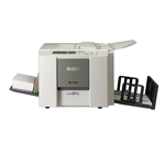
ЦЕНА:
360 800 p
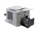
ЦЕНА:
503 400 p
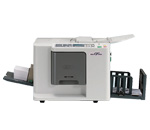
ЦЕНА:
518 480 p
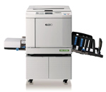
ЦЕНА:
1 426 670 p
-
Catalog
-
Sign In
-
Contacts
-
Forum
-
Eng
- Error Codes
- Riso
- RZ370
- All codes
Error Codes List page 1
- Code: A01
- Description: Master feed error
- Causes: 201 Master-positioning sensor does not go ON even after the write pulse motor is activated during the master-positioning, master-cut, or master-loading operation. 202 Master-positioning sensor does not go OFF even when the write pulse motor is reversed during the master-positioning or at start of master-making operation. 211 Master-positioning sensor is ON during standby. 214 Master-positioning sensor is ON at the start of master making. 215 Faulty gate-array control for the write pulse motor (motor does not stop within set time).
- Remedy: Open the master-making unit and rewind the master material on the master roll, and then reset the master, or turn OFF the power and power back ON.
- Code: A02
- Description: Master loading error
- Causes: 509 Master-loading sensor was OFF when the master was checked at a specified drum angle during the master-loading operation.
- Remedy: Pull out the print cylinder and set it back.
- Code: A04
- Description: Master disposal error
- Causes: 303 Check Print Drum — Master disposal error / Master disposal jam.
- Remedy: Pull out the print drum and push it back in.
- Code: A05
- Description: Master present in the master disposal area
- Causes: 304 Master disposal jam sensor was ON at the completion of the master disposal. 312 Master disposal jam sensor was ON at the start of the master making. 315 Master disposal jam sensor was ON after the completion of the recovery movement.
- Remedy: Pull out master disposal box and place it back after removing the jammed master in the master disposal area, or turn OFF the power and power back ON.
- Code: A06
- Description: Check paper feed tray
- Causes: 403 Either the upper or lower safety switch of the paper-feed-tray is OFF. Note: This detection is not made when the machine is in low-power-mode (24V OFF).
- Remedy: Change the condition of the paper-feed-tray upper/lower safety switches to ON condition, or turn OFF the power and power back ON.
- Code: A07
- Description: Paper feed error
- Causes: 409 Paper-ejection sensor was OFF when the paper should have arrived, and the paper sensor was ON when the machine stopped (Paper misfeed). 412 Paper sensor was OFF three times in succession when a paper misfeed was detected (paper misfeed). 413 Paper sensor was still ON (detecting paper) when the paper should have went out from the sensor. 418 The paper sensor was ON at the start of machine operation when the START button was pressed. 429 Paper feed error (recovery error). 432 Paper sensor was ON when the machine went into paper feed retry movement after a paper misfeed.
- Remedy: