10 февраля 2023 г. 09:15

При работе промышленной электроники YASKAWA в системах вентиляции, теплоснабжения или автоматизированном производственном оборудовании часто возникают неисправности, распознать которые можно считав коды ошибок и произведя расшифровку этих кодов по инструкции на конкретную модель электронного оборудования. Наиболее частое использование в промышленном оборудовании получили следующие частотные преобразователи фирмы YASKAWA: Yaskawa V1000, Yaskawa J1000, Yaskawa A1000, Yaskawa L1000. В свою очередь серия Yaskawa V1000 включает в себя следующие модели: CIMR-VUBA0001, CIMR-VUBA0002, CIMR-VUBA0003, CIMR-VUBA0006, CIMR-VUBA0010, CIMR-VUBA0012, CIMR-VUBA0018, CIMR-VU2A0001, CIMR-VU2A0002, CIMR-VU2A0004, CIMR-VU2A0006, CIMR-VU2A0010, CIMR-VU2A0012, CIMR-VU2A0020, CIMR-VU2A0030, CIMR-VU2A0040, CIMR-VU2A0056, CIMR-VU2A0069, CIMR-VU4A0001, CIMR-VU4A0002, CIMR-VU4A0004, CIMR-VU4A0005, CIMR-VU4A0007, CIMR-VU4A0009, CIMR-VU4A0011, CIMR-VU4A0018, CIMR-VU4A0023, CIMR-VU4A0031, CIMR-VU4A0038. Своевременная расшифровка ошибок может значительно ускорить диагностику и ремонт преобразователей частоты, подробнее об этом написано здесь.
Частотные преобразователи YASKAWA имеют следующие распространенные ошибки:
Наиболее частые ошибки преобразователей YASKAWA V1000:
Ошибка bUS (error bUS) — ошибка коммуникационного модуля;
Ошибка CE (error CE) — ошибка связи MEMOBUSModbus;
Ошибка CF (error CF) — ошибка схемы управления;
Ошибка CoF (error CoF) — ошибка датчика тока;
Ошибка CPF02 (error CPF02) — ошибка АЦП;
Ошибка CPF03 (error CPF03) — ошибка ШИМ;
Ошибка CPF06 (error CPF06) — несоответствие параметров после замены платы управления или платы входных сигналов;
Ошибка CPF07 (error CPF07) — ошибка связи с платов входных сигналов;
Ошибка CPF08 (error CPF08) — ошибка памяти EEPROM;
Ошибка CPF11 (error CPF11) — ошибка памяти RAM;
Ошибка CPF12 (error CPF12) — ошибка FLASH памяти;
Ошибка CPF13 (error CPF13) — ошибка сторожевого таймера;
Ошибка CPF14 (error CPF14) — неиспраность схемы управления;
Ошибка CPF16 (error CPF16) — неисправность тактового генератора;
Ошибка CPF17 (error CPF17) — ошибка таймера;
Ошибка CPF18 (error CPF18) — неиспраность схемы управления;
Ошибка CPF19 (error CPF19) — неисправность схемы управления;
Ошибка CPF20 (error CPF20) — аппаратная неисправность RAM, FLASH, Watchdog, Clock;
Ошибка CPF21 (error CPF21) — аппаратная неисправность RAM, FLASH, Watchdog, Clock;
Ошибка CPF22 (error CPF22) — ошибка АЦП;
Ошибка CPF23 (error CPF23) — ошибка ШИМ;
Ошибка CPF24 (error CPF24) — ошибка Drive Capacity Signal;
Ошибка CPF25 (error CPF25) — плата входных сигналов повреждена или не установлена;
Ошибка dEv (error dEv)(отображается на дисплее, как «dEu») — нестабильная скорость;
Ошибка E5 (error E5)(отображается на дисплее, как «ES») — ошибка сторожевого таймера MECHATROLINK;
Ошибка EF0 (error EF0)(отображается на дисплее, как «EO») — неиспраность внешней опциональной платы;
Ошибка dWAL (error dWAL)(отображается на дисплее, как «dLJAL») — программная ошибка функции DriveWorksEZ;
Ошибка dWFL (error dWFL)(отображается на дисплее, как «dLJFL») — ошибка функции DriveWorksEZ;
Ошибка EF1 (error EF1) — внешняя неисправность по входу S1;
Ошибка EF2 (error EF2) — внешняя неисправность по входу S2;
Ошибка EF3 (error EF3) — внешняя неисправность по входу S3;
Ошибка EF4 (error EF4) — внешняя неисправность по входу S4;
Ошибка EF5 (error EF5) — внешняя неисправность по входу S5;
Ошибка EF6 (error EF6) — внешняя неисправность по входу S6;
Ошибка EF7 (error EF7) — внешняя неисправность по входу S7;
Ошибка Err (error Err) — ошибка запяси в память EEPROM;
Ошибка FbH (error FbH) — повышенное значение сигнала обратной связи PID регулятора;
Ошибка FbL (error FbL) — пониженное значение сигнала обратной связи PID регулятора, обрыв датчика;
Ошибка GF (error GF)(отображается на дисплее, как «6F», «CF») — короткое замыкание выхода ПЧ на землю;
Ошибка LF (error LF) — обрыв фазы на выходе инвертора;
Ошибка LF2 (error LF2) — небаланс тока на выходе ПЧ;
Ошибка nSE (error nSE)(отображается на дисплее, как «п5Е», «n5E») — ошибка функции Node Setup во время запуска;
Ошибка oC (error oC)(отображается на дисплее, как «0C») — перегрузка преобразователя;
Ошибка oFA00 (error oFA00) — ошибка связи с опциональной платой;
Ошибка oFA01 (error oFA01) — неисправность опционального модуля;
Ошибка oFA03 (error oFA03) — неисправность опциональной платы;
Ошибка oFA04 (error oFA04) — неисправность опциональной платы;
Ошибка oFA30 (error oFA30) — неисправность опциональной платы id30;
Ошибка oFA31 (error oFA31) — неисправность опциональной платы id31;
Ошибка oFA32 (error oFA32) — неисправность опциональной платы id32;
Ошибка oFA33 (error oFA33) — неисправность опциональной платы id33;
Ошибка oFA34 (error oFA34) — неисправность опциональной платы id34;
Ошибка oFA35 (error oFA35) — неисправность опциональной платы id35;
Ошибка oFA36 (error oFA36) — неисправность опциональной платы id36;
Ошибка oFA37 (error oFA37) — неисправность опциональной платы id37;
Ошибка oFA38 (error oFA38) — неисправность опциональной платы id38;
Ошибка oFA39 (error oFA39) — неисправность опциональной платы id39;
Ошибка oFA40 (error oFA40) — неисправность опциональной платы id40;
Ошибка oFA41 (error oFA41) — неисправность опциональной платы id41;
Ошибка oFA42 (error oFA42) — неисправность опциональной платы id42;
Ошибка oFA43 (error oFA43) — неисправность опциональной платы id43;
Ошибка oH (error oH)(отображается на дисплее, как «0H») — перегрев радиатора инвертора;
Ошибка oH1 (error oH1)(отображается на дисплее, как «0H1») — перегрев радиатора инвертора;
Ошибка oH3 (error oH3)(отображается на дисплее, как «0H3») — перегрев двигателя по датчику PTC1;
Ошибка oH4 (error oH4)(отображается на дисплее, как «0H4») — перегрев двигателя по датчику PTC2;
Ошибка oL1 (error oL1)(отображается на дисплее, как «0L1») — перегрузка двигателя;
Ошибка oL2 (error oL2)(отображается на дисплее, как «0L2») — перегрузка привода;
Ошибка oL3 (error oL3)(отображается на дисплее, как «0L3») — перегрузка по уставкам L6-02, L6-03;
Ошибка oL4 (error oL4)(отображается на дисплее, как «0L4») — перегрузка по уставкам L6-05, L6-06;
Ошибка oL5 (error oL5)(отображается на дисплее, как «0L5») — механическая неисправность по уставке L6-08;
Ошибка oL7 (error oL7)(отображается на дисплее, как «0L7») — ошибка торможения по уставке n3-04;
Ошибка oPr (error oPr)(отображается на дисплее, как «0Pr») — ошибка связи с внешней панелью оператора;
Ошибка oS (error oS)(отображается на дисплее, как «0S», «05», «o5») — превышение заданной скорости;
Ошибка ov (error ov)(отображается на дисплее, как «ou», «0u», «0v») — перенапряжение;
Ошибка PF (error PF) — обрыв фазы на входе ПЧ;
Ошибка PGo (error PGo)(отображается на дисплее, как «PG0») — импульсный вход не подключен;
Ошибка rH (error rH) — перегрев тормозного резистора;
Ошибка rr (error rr) — неисправность встроенного тормозного транзистора;
Ошибка SC (error SC)(отображается на дисплее, как «5C») — короткое замыкание IGBT-модуля;
Ошибка SEr (error SEr)(отображается на дисплее, как «5Er») — ошибка функции поиска скорости speed search;
Ошибка STo (error STo)(отображается на дисплее, как «5Го», «5Г0», «SГo») — неправильные параметры двигателя;
Ошибка UL3 (error UL3) — пониженный ток нагрузки по уставкам L6-02, L6-03;
Ошибка UL4 (error UL4) — пониженный ток нагрузки по уставкам L6-05, L6-06;
Ошибка UL5 (error UL5)(отображается на дисплее, как «ULS») — механическая неисправность по уставке L6-08;
Ошибка Uv1 (error Uv1)(отображается на дисплее, как «Uu1») — пониженное напряжение шины постоянного тока;
Ошибка Uv2 (error Uv1)(отображается на дисплее, как «Uu2») — пониженное напряжение источника питания схемы управления;
Ошибка Uv3 (error Uv3)(отображается на дисплее, как «Uu3») — неисправность схемы защиты от бросков тока;
Контактная информация
Время выполнения запроса: 0,002366065979 секунды.
Данное описание аварий и неисправностей подходит для преобразователей частоты серии A1000 фирмы Yaskawa (аналогично Omron-Yaskawa, OYMC)
Список ошибок
Детализация ошибок
Список заказных кодов
Обнаружение ошибок производится с целью предотвращения повреждения преобразователя частоты. Для работы с ошибками преобразователей частоты фирмы Yaskawa в первую очередь необходимо знать назначение индикаторов модуля ЦПУ.

Для правильного определения мер по устранению проблемы необходимо четко различать ошибки (faults) и предупреждения (alarms).
Когда ПЧ обнаруживает ошибку:
- • На дисплее цифровой панели отображается соответствующий текстовый код ошибки; индикатор «ALM» не погаснет до тех пор, пока ошибка не будет сброшена.
- • С выхода ПЧ снимается напряжение, двигатель останавливается самовыбегом.
- • Для некоторых ошибок пользователь может выбрать способ остановки двигателя.
- • Клеммы выхода сигнализации ошибки MA-MC замыкаются, а клеммы MB-MC размыкаются.
Пока ошибка не устранена, работу преобразователя частоты возобновить невозможно
Когда ПЧ выдает предупреждение или обнаруживает незначительную ошибку:
- • На дисплее цифровой панели отображается соответствующий текстовый код предупреждения или незначительной ошибки; индикатор «ALM» мигает.
- • Как правило, преобразователь не прекращает вращение двигателя, хотя для некоторых предупреждений пользователь может выбрать способ остановки.
- • Если один из многофункциональных релейных выходов сконфигурирован для сигнализации незначительных ошибок (H2- = 10), этот выход замыкается (предупреждение к замыканию выхода не приводит).
Для сброса незначительной ошибки или предупреждения следует устранить причину возникновения
Для более детального анализа аварии, вы можете просмотреть детальную информацию по текущей ошибке (U2 — детализация ошибки) и журнал шибок (U3 — хронология ошибок), в котором содержится список предыдущих аварий.
Краткий список ошибок
Ниже содержится краткий обзор возможных видов ошибок.
boL — Ошибка перегрузки тормозного транзистора
bUS — Ошибка дополнительного интерфейса
CE — Ошибка интерфейса MEMOBUS/Modbus
CF — Ошибка регулирования
CPF00, CPF01- Ошибка схемы управления
CPF02 — Ошибка А/Ц-преобразования
CPF03 -Ошибка подключения платы управления
CPF06 — Ошибка данных памяти ЭСППЗУ
CPF07, CPF08 — Ошибка подключения клеммной платы
CPF20, CPF21 — Ошибка схемы управления
CPF22 — Ошибка гибридной ИС
CPF23 — Ошибка подключения платы управления
CPF24 — Ошибка сигнала мощности привода
CPF26…CPF34 — Ошибка схемы управления
dEv — Чрезмерное отклонение скорости (для режима управления с PG)
dv1 — Обнаружение спада импульса Z
dv2 — Ошибочное обнаружение импульса Z вследствие помехи
dv3 — Обнаружение инверсии
dv4 — Обнаружение предотвращения инверсии
E5 — Ошибка сторожевого таймера SI-T3
EF0 — Внешняя ошибка от дополнительной карты
EF1…EF8 — Внешняя ошибка (входная клемма S1…S8)
Err — Ошибка записи ЭСППЗУ
oFC03, oFC11 — Ошибка дополнительной карты (CN5-C)
oFC12…oFC17 — Ошибка подключения дополнительной карты (CN5-C)
oFC30… oFC43 — Ошибка дополнительной карты (CN5-C)
oH, oH1 — Перегрев радиатора
oH3 — Перегрев двигателя 1 (вход PTC)
oH4 — Перегрев двигателя 2 (вход PTC)
oL1 — Перегрузка двигателя
oL2 — Перегрузка преобразователя частоты
oL3 — Обнаружение превышения момента 1
oL4 — Обнаружение превышения момента 2
oL5 — Обнаружение износа механической системы 1
oL7 — OL при торможении с повышенным скольжением
oPr — Ошибка подключения панели управления
oS — Превышение скорости (для режима управления с PG)
FAn — Ошибка внутреннего вентилятора
FbH — Чрезмерный уровень сигнала обратной связи ПИД
FbL — Потеря сигнала ОС ПИД-регулятора
GF — Замыкание на землю
LF — Потеря выходной фазы
LF2 — Асимметрия токов
nSE — Ошибка настройки узла
oC — Перегрузка по току
oFA00, oFA12…oFA17, oFA30…oFA43 — Ошибка подключения дополнительной карты (CN5-A)
oFA01, oFA03…oFA06, oFA10, oFA11 — Ошибка дополнительной карты (CN5-A)
oFb00, oFb12…oFb17, oFb30…oFb43 — Ошибка подключения дополнительной карты (CN5-B)
oFb01, oFb02, oFb03, oFb11 — Ошибка дополнительной карты (CN5-B)
oFC00 — Ошибка подключения дополнительной карты (CN5-C)
oFC01, oFC02 — Ошибка дополнительной карты (CN5-C)
ov — Превышение напряжения
PF — Пропадание фазы на входе
PGo — Отсоединение PG (для режима управления с PG)
PGoH — Аппаратный сбой PG (при использовании PG-X3)
rF — Ошибка тормозного резистора
rH — Резистор динамического торможения
rr — Транзистор динамического торможения
SEr — Превышение числа повторных попыток определения скорости
STo — Обнаружение выхода из синхронизма
SvE — Ошибка серворегулирования на 0 Гц
UL3 — Обнаружение пониженного момента 1
UL4 — Обнаружение пониженного момента 2
UL5 — Обнаружение износа механической системы 2
Uv1 — Пониженное напряжение
Uv2 — Пониженное напряжение питания схемы управления
Uv3 — Ошибка схемы плавного заряда
voF — Ошибка определения выходного напряжения
Существуют также коды незначительных ошибок и предупреждений, ошибки управления, ошибки автонастройки, ошибки копирования.
Для детального описания ошибок пользуйтесь руководством по эксплуатации. Обратитесь в наш сервисный центр, если не можете разобраться с ошибкой сами, и мы поможем Вам.
Детализация ошибок
Для детального анализа ошибки посмотрите в меню U2 — детализация ошибки:
U2-01 (80H) — Текущая ошибка (Все режимы)
U2-02 (81H) — Предыдущая ошибка (Все режимы)
U2-03 (82H) — Задание частоты при предыдущей ошибке (Все режимы)
U2-04 (83H) — Выходная частота при предыдущей ошибке (Все режимы)
U2-05 (84H) — Выходной ток при предыдущей ошибке (Все режимы)
U2-06 (85H) — Скорость двигателя при предыдущей ошибке (Режимы: V/f V/f w/P G OLV CLV OLV/PM AOLV/PM CLV/PM)
U2-07 (86H) — Выходное напряжение при предыдущей ошибке (Все режимы)
U2-08 (87H) — Напряжение шины постоянного тока при предыдущей ошибке (Все режимы)
U2-09 (88H) — Выходная мощность при предыдущей ошибке (Все режимы)
U2-10 (89H) — Задание вращающего момента при предыдущей ошибке (Режимы V/f V/f w/PG OLV CLV OLV/PM AOLV/PM CLV/PM)
U2-11 (8AH) — Состояние входных клемм при предыдущей ошибке (Все режимы)
U2-12 (8BH) — Состояние выходных клемм при предыдущей ошибке (Все режимы)
U2-13 (8CH) — Состояние привода при предыдущей ошибке (Все режимы)
U2-14 (8DH) — Общее время наработки при предыдущей ошибке (Все режимы)
U2-15 (7E0H) — Задание скорости после мягкого пуска при предыдущей ошибке (Все режимы)
U2-16 (7E1H) — ок двигателя по оси q при предыдущей ошибке (Режимы: V/f V/f w/PG OLV CLV OLV/PM AOLV/PM CLV/PM)
U2-17 (7E2H) — ок двигателя по оси d при предыдущей ошибке (Режимы: V/f V/f w/PG OLV CLV OLV/PM AOLV/PM CLV/PM )
U2-19 (7ECH) — Отклонение ротора при предыдущей ошибке (Режимы: V/f V/f w/PG OLV CLV OLV/PM AOLV/PM CLV/PM )
U2-20 (8EH) — Температура радиатора при предыдущей ошибке (Все режимы)
Список заказных кодов
Полный список заказных кодов серии A1000 класса 200 В для которых подходит описание аварий.
CIMR-A4A0002 ,CIMR-A4A0004 ,CIMR-A4A0005 ,CIMR-A4A0007 ,CIMR-A4A0009 ,CIMR-A4A0011 ,CIMR-A4A0018 ,CIMR-A4A0023 ,CIMR-A4A0031 ,CIMR-A4A0038 ,CIMR-A4A0044 ,CIMR-A4A0058 ,CIMR-A4A0072 ,CIMR-A4A0088 ,CIMR-A4A0103 ,CIMR-A4A0139 ,CIMR-A4A0165 ,CIMR-A4A0208 ,CIMR-A4A0250 ,CIMR-A4A0296 ,CIMR-A4A0362 ,CIMR-A4A0414 ,CIMR-A4A0515 ,CIMR-A4A0675
Полный список заказных кодов серии A1000 класса 200 В для которых подходит описание аварий.
CIMR-A2A0004, CIMR-A2A0006, CIMR-A2A0010, CIMR-A2A0012, CIMR-A2A0021, CIMR-A2A0030, CIMR-A2A0040, CIMR-A2A0056, CIMR-A2A0069, CIMR-A2A0081, CIMR-A2A0110, CIMR-A2A0138, CIMR-A2A0169, CIMR-A2A0211, CIMR-A2A0250, CIMR-A2A0312, CIMR-A2A0360, CIMR-A2A0415
#1
![]()
OFFLINE
kapez
- Из:Saint-Petersburg
Отправлено 13 Ноябрь 2014 — 19:14
Добрый день!
Столкнулся с проблемой на Yaskawa (omron) V1000
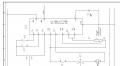
Данный частотник установлен на штукатурной станции, и вот в один прекрасный момент данный частотник выдал ошибку EF3. судя по инструкции это указывает на входящий контакт S3. Но у нас он никак не задействован. провода в нем нет никакого. С какого-то перепугу вот выдал такую ошибку. В итоге не ясна причина данного инцидента и собственно непонятно что дальше делать чтобы устранить причину. поторное включение выключение не дает никаких результатов. Подскажите может чего.
Схема подключения. вобщем из-за ошибки инициируется H1 и дальше не запускается агрегат.
Спасибо.
-
0
- Наверх
#2
![]()
lkbyysq
- Пол:Мужчина
- Город:Санкт-Петербург
- Из:Санкт-Петербург
Отправлено 13 Ноябрь 2014 — 19:23
В инструкции написано «• Проверьте функции, назначенные цифровым входам.»
Проверили?
-
1
- Наверх
#3
![]()
kapez
- Из:Saint-Petersburg
Отправлено 13 Ноябрь 2014 — 19:24
В инструкции написано «• Проверьте функции, назначенные цифровым входам.»
Проверили?
Если бы еще в инструкции было написано как их проверить =) Отдельное спасибо если и это поясните.
-
0
- Наверх
#4
![]()
lkbyysq
- Пол:Мужчина
- Город:Санкт-Петербург
- Из:Санкт-Петербург
Отправлено 13 Ноябрь 2014 — 19:35
-
1
- Наверх
#5
![]()
kapez
- Из:Saint-Petersburg
Отправлено 13 Ноябрь 2014 — 19:41
Спасибо большое! По результатам отпишусь. Завтра планируется проверка этого дела.
-
0
- Наверх
#6
![]()
lkbyysq
- Пол:Мужчина
- Город:Санкт-Петербург
- Из:Санкт-Петербург
Отправлено 13 Ноябрь 2014 — 19:46
Мануал под рукой имейте. Мало ли чего там еще, пароли может стоят. Логику телодвижений я написал.
Сообщение отредактировал lkbyysq: 13 Ноябрь 2014 — 19:46
-
0
- Наверх
#7
![]()
kapez
- Из:Saint-Petersburg
Отправлено 14 Ноябрь 2014 — 21:47
Спасибо =) По вашему алгоритму все четко, только упустили из виду 1 маленькую деталь, которая для неопытного человека становится камнем преткновения. В меню Par я попал без проблем, только там мне доступно всего два параметра A1-01 и A1-04 и все. Туда сюда их крутил но что с этим делать не понятно было. Пока более опытный человек не науськал поменять A1-01 значение 0002 задать. Тогда то и открылись мне все параметры для настройки и, добравшись до H1-03, я узрел в нем значение 24… ума не приложу откуда оно там взялось, но поменяв его на F, все завертыхалось =)
Еще раз огромное спасибо!
-
0
- Наверх
#8
![]()
3D-BiG
- Пол:Мужчина
- Город:Ареал обитания — вся страна, но обычно встречаюсь в Новосибирске…
- Интересы:Полежать на диване, пофлудить на форуме….
- Из:СССР
Отправлено 15 Ноябрь 2014 — 00:18
Пока более опытный человек не науськал поменять A1-01 значение 0002 задать. Тогда то и открылись мне все параметры для настройки
А вас предупреждали:
Мануал под рукой имейте. Мало ли чего там еще, пароли может стоят. Логику телодвижений я написал.
Сообщение отредактировал 3D-BiG: 15 Ноябрь 2014 — 00:19
-
0
Лужу, паяю, станки ЧПУ починяю….
Еще частенько здесь болтаю: Телеграм сообщество ЧПУшников: t.me/cncunion
- Наверх
#9
![]()
kapez
- Из:Saint-Petersburg
Отправлено 15 Ноябрь 2014 — 01:06
Ну какой же русский человек читает инструкцию =)
-
0
- Наверх
#10
![]()
T-Rex
- Пол:Мужчина
- Из:Йошкар-Ола
Отправлено 15 Ноябрь 2014 — 02:29
добравшись до H1-03, я узрел в нем значение 24… ума не приложу откуда оно там взялось
Так ведь штукатурная станция… С электронным оборудованием, эксплуатируемым на стройплощадках и питающимся от временной электросети (которую если не сварочным аппаратом перегрузят, так на гусеницы бульдозера намотают), каких только чудес не случается…
-
0
- Наверх
#11
![]()
kapez
- Из:Saint-Petersburg
Отправлено 05 Июнь 2015 — 14:34
Добрый день!
Имеем ошибку частотника oC — ноль Ц по русски=) и лопнувший конденсатор. который ,как мне сказали производители техники, впаяли туда чтобы пройти европейские нормы по защите среды от эл. магнитного излучения или чет такое. вобщем без него мол должно все работать. кондей и провода к нему видно где выходят и вроде как нагрузки смысловой не несут. Единственное что взорвавшийся кондей несколько окрапил внутри окалинами все. проверил все платы. на них нигде окалины не попали и дорожки не замкнули. а так на корпусе и других конденсаторах они есть.
в мануале все четко написано:
Перегрузка по
току
1)Короткое замыкание или пробой на
землю на стороне выхода привода
2)Слишком высокая нагрузка.
3)Слишком малое время разгона/
торможения.
4)Неправильные настройки данных
двигателя или характеристик
частотного управления.
5)На выходе был включен магнитный
контактор.
• Проверьте выходную схему и
двигатель на наличие коротких
замыканий или поврежденной
изоляции. Замените поврежденные
детали.-Проверено все в порядке. ничего нигде не звенит. проверено на другой машине на всякий случай. та же ошибка выскакивает.
• Проверьте машину на наличие
повреждений (шестерни и т. д.) и
восстановите все поврежденные
детали. — ну тут вобще нет проблемы, проверено все крутится нормально.
• Проверьте настройки параметров
привода. Проверил, где-то были не те, переустановил. но разгон торможение стоят 2,5 и 1,5 сек. по инструкции.
• Проверьте последовательность
коммутации контакторов на выходе — проверено. ну все в норме. провода и магнитные контакторы не трогались.
Проблема ,скажем так, возникла после того как машинка штукатурная была подключена через розетку!!! водяного насоса. удивительно но она даже работала. И её выключили сами. т.е. она не сгорела в процессе работы.
Схема проводки в приложении тут. красным выделено через что её подключили. прикинул по схеме. вроде пофиг что оттуда запитали. вполне может работать. другое дело что через автомат в обратную сторону, ну и фиг с ним=)
Вобщем включается нормально частотник. В режиме ожидания все в порядке. Только стоит инициировать запуск двигателя проще говоря замкнуть SC и SA тут же ошибка oC.
Подмогите в чем еще причина может быть. ни один сервис не берется диагностировать.
Прикрепленные изображения
-
0
- Наверх
#12
![]()
kapez
- Из:Saint-Petersburg
Отправлено 05 Июнь 2015 — 16:35
Может пригодится кому, мануал на русском для V1000 https://yadi.sk/i/6wZxP4kuh6Wxn (yaskawa_v1000.rar)
-
0
- Наверх
#13
![]()
T-Rex
- Пол:Мужчина
- Из:Йошкар-Ола
Отправлено 05 Июнь 2015 — 21:41
Вобщем включается нормально частотник. В режиме ожидания все в порядке. Только стоит инициировать запуск двигателя проще говоря замкнуть SC и SA тут же ошибка oC.
Ну, собственно, вариантов немного. Либо пробит один из транзисторов IGBT-моста (скорее всего, там модуль из 7 IGBT’шников, заменяемый целиком), либо проблемы с токоизмерительными цепями. В первом случае ремонт обойдется дорого, а во втором перспективы успешного ремонта и вовсе туманны — поэтому никто и не берется.
-
0
- Наверх
#14
![]()
kapez
- Из:Saint-Petersburg
Отправлено 06 Июнь 2015 — 16:23
Еще у меня при включении в основном меню F44.69 вместо 50.00 почему-то. как это поменять и какого фига не 50 герц частота. включаю то в обычную розетку.
Подскажите точнее что это за IGBT мост, может где на рисунке обвести или понять где находится. А то я электронике полный ноль=)
-
0
- Наверх
#15
![]()
3D-BiG
- Пол:Мужчина
- Город:Ареал обитания — вся страна, но обычно встречаюсь в Новосибирске…
- Интересы:Полежать на диване, пофлудить на форуме….
- Из:СССР
Отправлено 06 Июнь 2015 — 16:42
Подскажите точнее что это за IGBT мост, может где на рисунке обвести или понять где находится. А то я электронике полный ноль=)
IGBT мост это такая большая хрень, что прикручена к радиатору, который на дне — это те самые силовые ключи, которые и формируют 3 фазы, что идут на двигатель… Если пытаться их купить поштучно, а не партией от мешка и выше, то выйдет такой мостик обычно в от 1/2 до 2/3 стоимости частотника… Но не факт, что замена поможет…
Сообщение отредактировал 3D-BiG: 06 Июнь 2015 — 23:41
-
0
Лужу, паяю, станки ЧПУ починяю….
Еще частенько здесь болтаю: Телеграм сообщество ЧПУшников: t.me/cncunion
- Наверх
#16
![]()
T-Rex
- Пол:Мужчина
- Из:Йошкар-Ола
Отправлено 06 Июнь 2015 — 23:40
Еще у меня при включении в основном меню F44.69 вместо 50.00 почему-то. как это поменять
Ну вы, однако… Сами же дали ссылку на мануал к этой Яскаве V1000 на русском языке, и сами же до сих пор в этот мануал не заглядывали. «F» — это частота трехфазного переменного тока, которую частотный преобразователь будет выдавать на управляемый им электродвигатель.
Насчет «как поменять» — а надо менять? Возможно, у вас на этой штукатурной станции есть средства для оперативной регулировки скорости вращения миксера (например, потенциометр с ручкой-«крутилкой» — тогда покрутите ее и увидите, как цифры после «F» меняются).
и какого фига не 50 герц частота. включаю то в обычную розетку.
А при чем тут частота тока в розетке? Это у вас частотный преобразователь, а не частотомер…
-
0
- Наверх
#17
![]()
kapez
- Из:Saint-Petersburg
Отправлено 08 Июнь 2015 — 13:55
Заглядывал, только не искушенному пользователю сложно связать эту частоту с потенциометром=)
т.е. больше вариантов никаких кроме замены частотника ?
Мост в принципе не заменить мне. Низ прикручен, верх с ним спаян, отпаивать точно не буду,а то хуже станет =)
-
0
- Наверх
#18
![]()
T-Rex
- Пол:Мужчина
- Из:Йошкар-Ола
Отправлено 08 Июнь 2015 — 15:17
т.е. больше вариантов никаких кроме замены частотника ?
Ну, навскидку — да, больше никаких.
Из своей практики: ремонт частотника в кустарных условиях — всегда лотерея. Устройство сложное, принципиальных электрических схем на его «кишки» нет, приходится устраивать «реверс-инжиниринг» с разрисовыванием кусков схемы по дорожкам платы. Времени на это уходит уйма (и само собой, ни один специалист-ремонтник не хочет тратить его бесплатно), а положительный результат вовсе не гарантирован.
Например, валяется у меня в хламе Leroy-Somer’овский сервопривод (по сути, тоже частотник), жалующийся на пониженное напряжение в «DC power stage». Напряжение на самом деле нормальное, согласующие цепочки тоже проверены на исправность — судя по всему, причина в неисправности микросхемы, куда АЦП встроен. Ну и что мне радости от этого знания, учитывая, что эта самая микросхема — заказная БИС, кем-то изготовленная по спецзаказу и спецификации Leroy-Somer, и в свободную продажу она никогда не поступала?
-
0
- Наверх
#19
![]()
kapez
- Из:Saint-Petersburg
Отправлено 08 Июнь 2015 — 15:31
Спасибо всем=) пошел заказывать новый.
-
0
- Наверх
6.3
u
Types of Alarms, Faults, and Errors
Check the LED operator for information about possible faults if the drive or motor fails to operate.
Digital LED Operator on page
If problems occur that are not covered in this manual, contact the nearest Yaskawa representative with the following
information:
• Drive model
• Software version
• Date of purchase
• Description of the problem
Table 6.4
contains descriptions of the various types of alarms, faults, and errors that may occur while operating the drive.
Contact Yaskawa in the event of drive failure.
Type
When the drive detects a fault:
• The digital operator displays text that indicates the specific fault and the ALM indicator LED remains lit until the fault
is reset.
• The fault interrupts drive output and the motor coasts to a stop.
Faults
• Depending on the setting, the drive and motor may stop via different methods than listed.
• If a digital output is programmed for fault output (H2-oo = E), it will close if a fault occurs.
When the drive detects a fault, it will remain inoperable until that fault has been reset.
page
When the drive detects an alarm or a minor fault:
• The digital operator displays text that indicates the specific alarm or minor fault and the ALM indicator LED flashes.
• The motor does not stop.
Minor Faults and
Alarms
• One of the multi-function contact outputs closes if set to be tripped by a minor fault (H2-oo = 10), but not by an alarm.
• The digital operator displays text indicating a specific alarm and ALM indicator LED flashes.
Remove the cause of an alarm or minor fault to automatically reset.
When parameter settings conflict with one another or do not match hardware settings (such as with an option card), it
results in an operation error.
When the drive detects an operation error:
• The digital operator displays text that indicates the specific error.
Operation Errors
• Multi-function contact outputs do not operate.
When the drive detects an operation error, it will not operate the motor until the error has been reset. Correct the settings
that caused the operation error to reset.
Tuning errors occur while performing Auto-Tuning.
When the drive detects a tuning error:
• The digital operator displays text indicating the specific error.
Tuning Errors
• Multi-function contact outputs do not operate.
• Motor coasts to stop.
• Remove the cause of the error and repeat the Auto-Tuning process.
u
Alarm and Error Displays
n
Faults
When the drive detects a fault, the ALM indicator LEDs remain lit without flashing. If the LEDs flash, the drive has
detected a minor fault or alarm.
as overvoltage or external faults can trip both faults and minor faults, therefore it is important to note whether the LEDs
remain lit or if the LEDs flash.
LED Operator Display
bUS
Option Communication Error
MEMOBUS/Modbus
CE
Communication Error
CF
Control Fault
CoF
Current Offset Fault
YASKAWA ELECTRIC SIEP C710606 16C YASKAWA AC Drive – V1000 Technical Manual
78.
Table 6.4 Types of Alarms, Faults, and Errors
Drive Responses to Alarms, Faults, and Errors
279.
Refer to Minor Faults and Alarms on page 250
Table 6.5 Fault Displays
Name
6.3 Drive Alarms, Faults, and Errors
Pg.
LED Operator Display
253
CPF02 A/D Conversion Error
CPF03 PWM Data Fault
253
253
CPF06
254
Refer to Using the
Refer to Fault Reset Methods on
for more information. Conditions such
Name
Drive Specification Mismatch
during Terminal Board or Control
Board Replacement
6
Pg.
254
254
254
249
- Manuals
- Brands
- YASKAWA Manuals
- Controller
- V1000 Series
Manuals and User Guides for YASKAWA V1000 Series. We have 5 YASKAWA V1000 Series manuals available for free PDF download: Installation & Start-Up Manual, Technical Manual, Quick Start Manual, Option Manual
(The parameter data in the SERVOPACK is incorrect.)
(The parameter data in the SERVOPACK is incorrect.)
(The parameter setting was out of the setting range.)
(Detected when the power to the main circuit is turned ON.)
(Detected in the SERVOPACK main circuit power supply section.)
(The servomotor rotational speed exceeds the maximum.)
(Vibration was detected while executing the advanced autotuning, one-parameter tuning, EasyFFT, or tuning-less function.)
(Incremental)
(Absolute)
(Detected when the servo is ON.)
(Detected when the servo is ON.)
(Detected when the servomotor power is ON.)
(Reception error)
(Timer stop)
(Position error exceeded the value set in the excessive position error alarm level (Pn520).)
(With the main power supply ON, voltage was low for more than 1 second in an R, S, or T phase.)
(Detected when the main power supply was turned ON.)
Заказать оборудование Yaskawa
Купить Yaskawa v1000 ошибки в компании Олниса можно оптом или в розницу. Доставим Yaskawa v1000 ошибки в любой регион России. Можем предложить точный аналог. Работаем напрямую с производителем, не используя посредников.
Частотные преобразователи – достаточно надежное оборудование. Эти приборы широко применяются в условиях производства с целью преобразования входных сетевых параметров в выходные на разных частотах. Использование инверторов позволяет продлить срок эксплуатации электродвигателей, а также сэкономить электроэнергию. При работе с оборудованием иногда возникают сбои. Специалисты легко распознают их и устранят подобные погрешности эксплуатации.
.jpg "Yaskawa v1000 ошибки")
Чтобы своевременно обнаружить коды ошибок и сделать расшифровку, а также устранить неисправность стоит рассмотреть основные виды ошибок для Yaskawa V1000:
- bUS – выдает неисправность коммуникационного модуля;
- CE – нет стыковки с MEMOBUSModbus;
- CF – неправильные настройки управления;
- CoF – датчик электротока неисправен;
- CPF16 – тактовый генератор вышел из строя;
- CPF20, CPF21 – аппаратная неисправность;
- CPF13, CPF17 – таймер неисправен;
- CPF25 – плата неисправна или отсутствует;
- CPF02, CPF22 – неполадки связанные с АЦП;
- CPF03, CPF23 – ошибка ШИМ;
- CPF06 – плата неправильно подключена к управляющему элементу;
- CPF14, 18, 19 – схема управления повреждена;
- CPF24 – проблемы в DCSl;
- CPF07 – нет связи входного сигнала с платой;
- CPF08 – проблемы с памятью;
- CPF12 – неполадки запоминающей флеш-карты;
- dEu – скорость работы, требуется отладка;
- E5 или ES – отключился сторожевой таймера;
- EF0 или EO – внешняя плата не работает;
- dLJAL – вышла из функции DWZ;
- EF1-7 – внешняя неисправность, с обозначением какой именно вход вышел из строя 1-7;
- Err – ошибка записи или проблемы с памятью устройства;
- FbH – повышен сигнал PID регулятора, соответственно FbL – понижен.
.jpg "Yaskawa v1000 ошибки")
Это основные категории ошибок, но тем не менее есть уйма преимуществ частотников. Все оборудование отличается:
- Высокой надежностью. На протяжении всего срока эксплуатации они обеспечивают до трех миллионов гарантированных запусков даже при максимальной нагрузке.
- Простой эксплуатацией. Кроме того, у этого прибора имеется функция автоматической настройки без вращения, которая помогает провести измерения данных эквивалентной схемы двигателя при его запуске. Это значит, что при сборе информации для векторного управления больше не требуется отсоединять лифтовое оборудование.
- Экономичностью. Даже используя инвентор при высоких температурах происходит выбор одного и того же значения мощности. Кроме того, преобразователь имеет четыре встроенных реле, установка которых позволила исключить другие компоненты пульта управления. С помощью них осуществляется прямое управление тормозами и контакторами двигателя.
- Интегрированными средствами безопасности. Даже в случае внезапных сбоев в подаче электропитания, частотный привод позволит довести лифт до требуемой остановки с помощью дополнительного источника питания. Кроме того, в частотниках имеется особая схема с биполярными транзисторами, которая обеспечивает несколько уровней защиты от перегрузки по току.
- Высокой производительностью. Прибор имеет функцию компенсации и скольжения, что обеспечивает точность регулировки скорости и оптимальную балансировку, а значит и комфорт для пассажиров.
Доставка и покупка частотников
Приобрести частотный преобразователь и любое другое оборудование с целью автоматизации производства можно в компании «Олниса». Мы на протяжении многих лет поставляем качественное оборудование от надежных производителей по всем городам России и странам СНГ. На всю продукцию имеется долгосрочная гарантия.