Она означает что переполнен бункер с отработанным тонером. Дело в том, что технология лазерной печати построена таким образом, что в процессе печати принтера неизбежно появляется “лишний” отработанный тонер. Он не подходит для повторного использования и поэтому складируется в отдельный бункер, который присутствует либо на самом печатающем картридже, либо стоит как отдельный элемент принтера.
Чтобы не допустить полное его заполнение и выход отработанного тонера наружу (а он является летучим и весьма вредным веществом, крайне не рекомендуемым для вдыхания) в большинстве лазерных принтеров реализована система слежения за его наполнением. И ошибка c7990 на принтерах kyocera как раз и есть тот самый сигнал, который говорит, что пора почистить бункер отработанного тонера.
Почему возникает
Суть лазерной печати заключается в нанесении тонера на поверхность фотовала, заряженного противоположенным током. Порошок накладывается на всю поверхность, но остается только на определенных участках. Весь лишний удаляется в специальную емкость, а оставшейся запекается на бумаге в печке.
В этом случае, нас интересует судьба только оставшегося в принтере тонера. Он автоматически помещается в бункер отходов. В дальнейшем не используется для печати. Легко догадаться, что эта емкость имеет свой ресурс. Когда он заканчивается, устройство должно предупредить пользователя, что следует предпринять определенные действия. Разные марки принтеров делают это по-своему, а Киосера выдает ошибку с7990.
Решение
Способы решения напрашиваются сами. Необходимо почистить отработанный тонер.
- Отключите принтер от электропитания. Вытяните шнур питания из розетки.
- Откройте переднюю крышку.
- Сейчас Вы увидите проявочный узел. Его вынимаем.
- Дальше идет фотобарабан, который вытягиваем за зеленные ручки, чтобы не повредить поверхность.
- Кладем его на стол, который предварительно нужно застелить старой газетой или бумагой.
- Осматриваем картридж и находим места, через которые извлекаются остатки тонера.
- Через эти отверстия нужно высыпать порошок.
Делайте это на улице или помещении, где нет сквозняка. Помните, что вещество очень вредно для человека и окружающей среды, так как изготовлено из нефти. Используйте резиновые перчатки, а если есть бытовой респиратор, его тоже можно применить, чтобы защититься от вредной пыли.
В целях профилактики дальнейшего возникновения ошибки c7990 на принтерах Kyocera следует проводить чистку отработки при каждой заправке новой порции порошка. Если пополнение не производите самостоятельно, то в сервисном центре это должны сделать, но напомнить не будет лишним.
Первый вариант сброса ошибки С7990
Этот вариант подойдет для некоторых моделей Kyocera. Делается это очень просто:
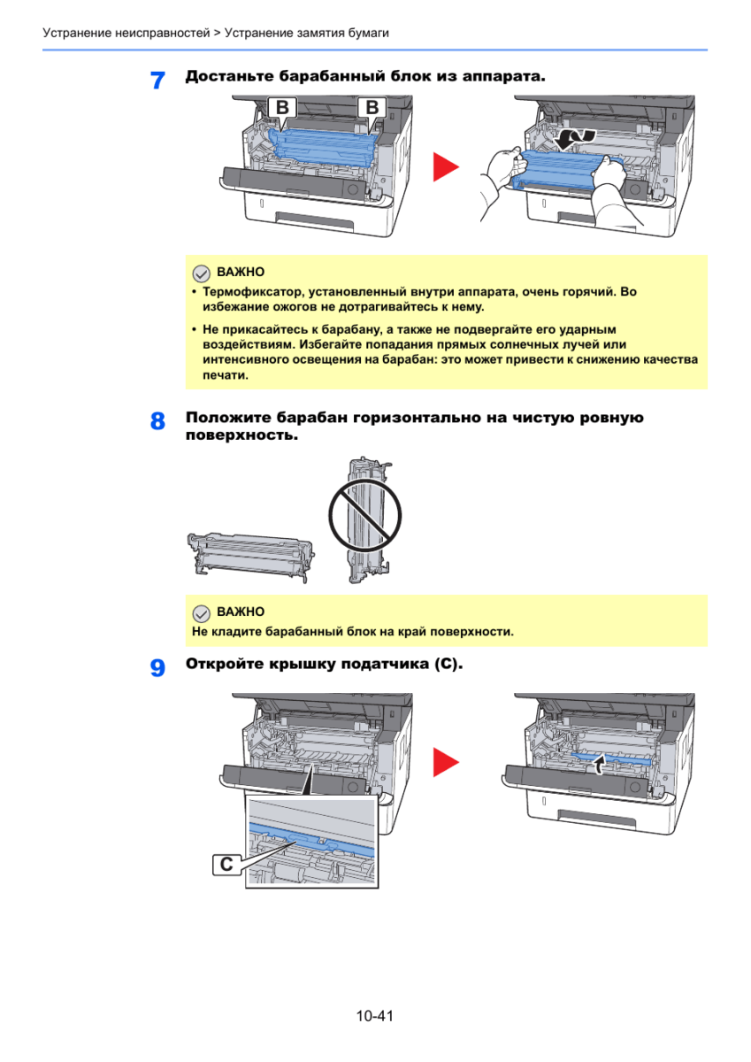
- Первое что требуется сделать это открытье переднюю крышку, как показано на рисунке:

Откройте переднюю крышку - Далее вытащите картридж с блоком проявки из МФУ. Можно отдельно, а можно и вместе.

Вытащите узел проявки из МФУ - Теперь извлеките узел фотобарабана из МФУ, удерживая за зеленые или синие рычаги обеими руками.

Извлеките узел барабана из МФУ
Инструкция: чистка бункера отработки на примере Kyocera P2235d / M2135dn / M2635dn / M2735dw
Для начала следует вынуть совместимый с МФУ Kyocera P2235d / M2135dn / M2635dn / M2735dw драм картридж DK-1150:
- откройте крышку с обратной стороны устройства;
- достаньте вал проявки;
- выньте драм-картридж.

Если у вас старая комплектация драм-картриджа DK-1150, тогда достаточно будет подковырнуть технологическое отверстие плоской отверткой и вытрясти отработку в герметичный пакет.

Новые драм-картриджи DK-1150 лишены технологического отверстия.
Проблему с чисткой можно решить полной разборкой детали (см. следующий раздел) или аккуратным сверлением бункера отработки. Получившееся отверстие затем стоит заклеить плотным скотчем, а уже при необходимости открывать.
Устранение ошибки C7990 – Шаг №1
Первое, что необходимо сделать, чтобы ошибка C7990 больше не беспокоила, это выключить печатающее устройство. Затем открыть переднюю крышку. Аккуратно, не торопясь, извлечь блок проявки. Извлекать нужно вместе с тонер-картриджем. Просто потяните его на себя, он выйдет.

Выключаем МФУ кнопкой включения/выключения питания. Открываем крышку и извлекаем блок проявки.
Шаг №2
После того как блок проявки извлечён, отложите его в сторону. Второе, что делаем, это извлекаем драм-юнит. Именно по его вине появилась на дисплее устройства ошибка C7990. Вытаскиваем драм также, как и блок проявки, потянув на себя. Тянуть нужно за специально предназначенные для этого зелёные вставки по бокам.

Извлекаем драм-юнит за специальные полукольца. Ошибка C7990 вызвана именно проблемами с драм-юнитом печатающего устройства Kyocera.
Шаг №3
Третье, на демонтированном драм-юните необходимо отщелкнуть небольшую крышку, закрывающую отверстие для чистки отсека отработки. Чтобы это сделать, поворачиваем драм зелёными вставками назад. По бокам находятся крышки. Отщелкнуть нужно одну из них, без разницы какую. Убрав закрывающую крышку высыпаем отработку.

При помощи плоской отвёртки отгибаем защёлки и снимаем крышку закрывающую бункер отработанного тонера.
После того как сняли крышку закрывающую бункер отработанного тонера в драме, высыпаем отработку через открывшуюся полость. Можно воспользоваться специальным пылесосом.
Шаг №4
Итак, отсек для отработанного тонера после проделанных манипуляций пуст. Причину вызвавшую ошибку C7990 на печатающем устройстве Kyocera устранили. Ставим крышечку на своё место. Вставляем драм-юнит, а затем блок проявки с тонер-картриджем в аппарат. Закрываем переднюю крышку устройства. Включаем МФУ и радуемся устранением проблемы.
Где находится бункер отработанного тонера?
Бункер расположен за блоком фотобарабана DK. Чтобы добраться до него необходимо вынуть блок проявки DV. Блок проявки — это блок, в который вставляется тонер-картридж.
При попытке использования картриджа – чип блокирует систему
Производители все время усложняют уровень защиты чипов в картриджах, теперь задача чипа заключается не в анализе оставшегося ресурса печати, а в блокировании возможности заправки картриджа.
Производителей можно разделить на две группы:
1. Производители, чья техника продолжает работу, когда счетчик отсчитал положенное количество копий, чип не блокирует работу заправленного картриджа.
К ним относятся: HP, Canon, Kyocera, Brother (у последнего применяются механические флажки).
В таких картриджах чип можно не менять, картридж продолжит работу и после заправки. В цветных картриджах чипы иногда требуется заменять, кроме счетчика они дополнительно хранят информацию о согласовании цветов.
2. Компании, которые устанавливают блокирующиеся чипы, которые препятствуют заправке картриджей.
К ним относятся: Lexmark, Samsung, Xerox, Pantum.
Чтобы картридж этих производителей продолжил свою работу после заправки, требуется обязательная установка нового чипа, даже полный картридж без чипа работать не будет. Либо, можно воспользоваться альтернативным путем – прошить принтер.
Прошивка принтера – это внесение изменений во внутреннее программное обеспечение самого аппарата так, чтобы принтер «забыл» о чипе и всегда думал, что картридж полный.
Какие еще есть причины возникновения ошибки с7990?
Причиной может послужить выход из строя датчика или платы управления. В этом случае лучше вызвать специалиста сервисного центра.
P.S. При переполненном бункера некоторые аппараты не всегда выдают ошибку С7990 на дисплее. Иногда пользователь об этом может узнать, когда принтер начинает трещать. Если вовремя не провести чистку, ломается шестерёнка. В этом случае, необходим уже ремонт или замена фотобарабана (бункера WT)
Дополнительная информация, касающаяся ошибки C7990
Если вы извлекли драм-юнит и на нём нет крышек закрывающих доступ для очистки отработки, то Вам нужно проделать отверстие самостоятельно. В некоторых моделях печатающих устройств Kyocera, отверстия на драм-юните для очистки отработки отсутствуют. После того как проделали отверстие и высыпали отработанный тонер обязательно заклейте отверстие скотчем! Далее установите драм и блок проявки на своё место, включите устройство. Ошибка C7990 больше Вас не побеспокоит, до следующего переполнения отработанным тонером.


Сброс сообщения «Замените МК» на МФУ kyocera 1035/2035/2535
Итак, делается это очень просто:
- Набираем на клавиатуре код: 10871087 и попадаем в сервисное меню
- Открываем программу u251
- Выбираете стрелочками «clear«
- Для выхода выполняете программу u001 (Не все модели поддерживают такой метод выхода из инженерного меню)
Если у Вас не получилось выйти из инженерного меню по программе u001, то просто выключите и включите Ваш аппарат.
Данным действием мы выполняем сброс счетчика обслуживания!
На этом все, надоедливая просьба исчезла. Мой совет — если МФУ начало просить заменить ему детали (по пробегу) и Вы еще ни разу в нем ничего не меняли, советую заранее прикупить новый Drum Unit DK-170 (проверьте, какой стоит у Вас!), так как это обычно первое, что выходит из строя и печать начинается с черными полосами.
Мы надеемся, что данная статья была полезна для Вас.
Расшифровка кода ошибки по индикаторам
Как расшифровать код ошибки по миганиям индикаторов?
Поле индикаторов в принтере Kyosera P2035D разделено на 8 секторов.

Информационных всего пять: пустые сектора, 1, 2, 3, 4.
Начало передачи кода – это мигание всех четырех секторов одновременно. Далее передается четырехзначный код последовательно. Каждое мигание – это цифра от 1 до 9 в двоичном формате.
Вес каждого сектора:
пустые сектора – 0
1 сектор – единица
2 сектор – двойка
3 сектор – четверка
4 сектор – восьмерка.
Например, код 7990 передается так. Мигают 1, 2, 3, 4 сектора одновременно (разделитель). Затем мигают 1, 2, 3 (1+2+4=7). После мигают 1, 4 (1+8=9). Потом повторяется 1, 4 (1+8=9). Завершает цикл миганием пустых секторов 0. Итого, 7990
Источник: http://complace.ru/remont-printerov-mfu/kyosera/remont-kyosera-p2035d/
Коды ошибок для популярной серии принтеров Kyocera FS-2100DN, FS-4100DN, FS-4200DN, FS-4300DN, а также для пришедших им на смену ECOSYS P3045dn, ECOSYS P3050dn, ECOSYS P3055dn, ECOSYS P3060dn.
1.Self-diagnostic function — Функция самодиагностики
Принтеры оснащены функцией самодиагностики. Когда проблема обнаружена, устройство прекращает печать и на панели управления отображается сообщение об ошибке. Сообщение об ошибке состоит из четырехзначного кода, указывающего на тип ошибки.
| Code | Contents | Causes | Check procedures/ corrective measures |
| 0100 | Backup memory device error | Defective flash memory. | Replace the main PWB and check for correct operation (see page 1-5-22). |
| Defective main PWB. | |||
| 0120 | MAC address data error For data in which the MAC address is invalid. | Defective flash memory. | Replace the main PWB and check for correct operation (see page 1-5-22). |
| Defective main PWB. | Replace the main PWB and check for correct operation (see page 1-5-22). | ||
| 0130 | Backup memory read/write error (main PWB) | Defective flash memory. | Replace the main PWB and check for correct operation (see page 1-5-22). |
| Defective main PWB. | |||
| 0140 | Backup memory data error (main PWB) | Defective flash memory. | Replace the main PWB and check for correct operation (see page 1-5-22). |
| Defective main PWB. | |||
| 0150 | Backup memory read/write error (engine PWB) Detecting engine PWB EEPROM communication error. | Improper installation engine PWB EEPROM. | Check the installation of the EEPROM and remedy if necessary. |
| Defective engine PWB. | Replace the engine PWB and check for correct operation (see page 1-5-22). | ||
| Device damage of EEPROM. | Contact the Service Administrative Division. | ||
| 0160 | Backup memory data error (engine PWB) | Defective EEPROM. | Replace the engine PWB and check for correct operation (see page 1-5-22). |
| Defective engine PWB. | |||
| 0170 | Billing counting error A checksum error is detected in the main and engine backup memories for the billing counters. | Data damage of EEPROM. | Contact the Service Administrative Division. |
| Defective PWB. | Replace the main PWB or the engine PWB and check for correct operation (see page 15-22, 1-5-22). | ||
| 0190 | Backup memory device error (engine PWB) | Defective engine PWB. | Replace the engine PWB and check for correct operation (see page 1-5-22). |
| 0800 | Image processing error JAM010x is detected twice. | Defective connector cable or poor contact in the connector. | Reinsert the connector. Also check for continuity within the connector cable. If none, replace the cable. Fuser thermistor 1/2 and fuser thermistor connect PWB(YC1/2) Fuser thermistor connect PWB(YC3) and engine PWB (YC21) |
| Defective fuser thermistor. | Replace the fuser thermistor connect PWB . | ||
| Replace the fuser unit (see page 1-5-19). | |||
| Defective engine PWB. | Replace the engine PWB and check for correct operation (see page 1-5-22). | ||
| Defective main PWB. | Replace the main PWB and check for correct operations page 1-5-22). | ||
| 0840 | Faults of RTC Unable to communicate with the RTC device normally. The RTC data is mismatched due to dead battery or short-circuit with the metal part. | Other RTC device failure due to dead battery or short-circuit with the metal part. | Restart the main unit and set the correct time from the operation panel. Repair it if the battery comes off from the main PWB. |
| Defective main PWB. | Replace the main PWB and check for correct operation (see page 1-5-22). | ||
| 1010 | Lift motor error (60/55/50 ppm model only) After cassette 1 is inserted, lift sensor does not turn on within 10 s. This error is detected five times successively. | Defective bottom plate elevation mechanism in the cassette. | Check to see if the bottom plate can move smoothly and repair it if any problem is found. |
| Defective connector cable or poor contact in the connector. | Reinsert the connector. Also check for continuity within the connector cable. If none, replace the cable. Lift motor and engine PWB (YC13) | ||
| Defective drive transmission system of the lift motor. | Check if the gears rotate smoothly. If not, grease the bushes and gears. Check for broken gears and replace if any. | ||
| Defective lift motor. | Replace the lift motor. | ||
| Defective engine PWB. | Replace the engine PWB and check for correct operation (see page 1-5-22). | ||
| 1020 | PF lift motor 1 error (paper feeder) After cassette 2 is inserted, PF lift sensor 1 does not turn on. This error is detected four times successively. | Defective bottom plate elevation mechanism in the cassette. | Check to see if the bottom plate can move smoothly and repair it if any problem is found. |
| Defective connector cable or poor contact in the connector. | Reinsert the connector. Also check for continuity within the connector cable. If none, replace the cable. PF lift motor 1 and PF main PWB (YC7) | ||
| Defective drive transmission system of the PF lift motor. | Check if the gears rotate smoothly. If not, grease the bushes and gears. Check for broken gears and replace if any. | ||
| Defective PF lift motor. | Replace the PF lift motor 1. | ||
| Defective PF main PWB. | Replace the PF main PWB (Refer to the service manual for the paper feeder). | ||
| 1030 | PF lift motor 2 error (paper feeder) After cassette 3 is inserted, PF lift sensor 2 does not turn on. This error is detected four times successively. | Defective bottom plate elevation mechanism in the cassette. | Check to see if the bottom plate can move smoothly and repair it if any problem is found. |
| Defective connector cable or poor contact in the connector. | Reinsert the connector. Also check for continuity within the connector cable. If none, replace the cable. PF lift motor 2 and PF main PWB (YC7) | ||
| Defective drive transmission system of the PF lift motor. | Check if the gears rotate smoothly. If not, grease the bushes and gears. Check for broken gears and replace if any. | ||
| Defective PF lift motor. | Replace the PF lift motor 2. | ||
| Defective PF main PWB. | Replace the PF main PWB (Refer to the service manual for the paper feeder). | ||
| 1040 | PF lift motor 3 error (paper feeder) After cassette 4 is inserted, PF lift sensor 3 does not turn on. This error is detected four times successively. | Defective bottom plate elevation mechanism in the cassette. | Check to see if the bottom plate can move smoothly and repair it if any problem is found. |
| Defective connector cable or poor contact in the connector. | Reinsert the connector. Also check for continuity within the connector cable. If none, replace the cable. PF lift motor 3 and PF main PWB (YC7) | ||
| Defective drive transmission system of the PF lift motor. | Check if the gears rotate smoothly. If not, grease the bushes and gears. Check for broken gears and replace if any. | ||
| Defective PF lift motor. | Replace the PF lift motor 3. | ||
| Defective PF main PWB. | Replace the PF main PWB (Refer to the service manual for the paper feeder). | ||
| 1050 | PF lift motor 4 error (paper feeder) After cassette 5 is inserted, PF lift sensor 4 does not turn on. This error is detected four times successively. | Defective bottom plate elevation mechanism in the cassette. | Check to see if the bottom plate can move smoothly and repair it if any problem is found. |
| Defective connector cable or poor contact in the connector. | Reinsert the connector. Also check for continuity within the connector cable. If none, replace the cable. PF lift motor 4 and PF main PWB (YC7) | ||
| Defective drive transmission system of the PF lift motor. | Check if the gears rotate smoothly. If not, grease the bushes and gears. Check for broken gears and replace if any. | ||
| Defective PF lift motor. | Replace the PF lift motor 4. | ||
| Defective PF main PWB. | Replace the PF main PWB (Refer to the service manual for the paper feeder). | ||
| 1140 | BPF lift motor upward error (Bulk paper feeder) BPF lift maximum sensor does not turn on. The lock signal of the motor is detected continuously three times. | Defective connector cable or poor contact in the connector. | Reinsert the connector. Also check for continuity within the connector cable. If none, replace the cable. BPF lift motor and BPF main PWB (YC4) |
| Defective drive transmission system of the motor. | Check if the gears rotate smoothly. If not, grease the bushes and gears. Check for broken gears and replace if any. | ||
| Defective BPF lift motor. | Replace the BPF lift motor. | ||
| Defective BPF main PWB. | Replace the BPF main PWB (Refer to the service manual for the paper feeder). | ||
| 1150 | BPF lift motor downward error (Bulk paper feeder) BPF lift minimum sensor does not turn on. The lock signal of the motor is detected continuously three times. When detecting an overcurrent detection signal. | Defective connector cable or poor contact in the connector. | Reinsert the connector. Also check for continuity within the connector cable. If none, replace the cable. BPF lift motor and BPF main PWB (YC4) |
| Defective drive transmission system of the motor. | Check if the gears rotate smoothly. If not, grease the bushes and gears. Check for broken gears and replace if any. | ||
| Defective BPF lift motor. | Replace the BPF lift motor. | ||
| Defective BPF main PWB. | Replace the BPF main PWB (Refer to the service manual for the paper feeder). | ||
| 1800 | Paper feeder 1 communication error A communication error is detected 10 times in succession. | Improper installation paper feeder. | Follow installation instruction carefully again. |
| Defective connector cable or poor contact in the connector. | Reinsert the connector. Also check for continuity within the connector cable. If none, replace the cable. PF main PWB (YC3) and engine PWB (YC22) | ||
| Defective engine PWB. | Replace the engine PWB and check for correct operation (see page 1-5-22). | ||
| Defective PF main PWB. | Replace the PF main PWB (Refer to the service manual for the paper feeder). | ||
| 1810 | Paper feeder 2 communication error A communication error is detected 10 times in succession. | Improper installation paper feeder. | Follow installation instruction carefully again. |
| Defective connector cable or poor contact in the connector. | Reinsert the connector. Also check for continuity within the connector cable. If none, replace the cable. PF main PWB (YC3) and engine PWB (YC22) | ||
| Defective PF main PWB. | Replace the PF main PWB (Refer to the service manual for the paper feeder). | ||
| 1820 | Paper feeder 3 communication error A communication error is detected 10 times in succession. | Improper installation paper feeder. | Follow installation instruction carefully again. |
| Defective connector cable or poor contact in the connector. | Reinsert the connector. Also check for continuity within the connector cable. If none, replace the cable. PF main PWB (YC3) and engine PWB (YC22) | ||
| Defective PF main PWB. | Replace the PF main PWB (Refer to the service manual for the paper feeder). | ||
| 1830 | Paper feeder 4 communication error A communication error is detected 10 times in succession. | Improper installation paper feeder. | Follow installation instruction carefully again. |
| Defective connector cable or poor contact in the connector. | Reinsert the connector. Also check for continuity within the connector cable. If none, replace the cable. PF main PWB (YC3) and engine PWB (YC22) | ||
| Defective PF main PWB. | Replace the PF main PWB (Refer to the service manual for the paper feeder). | ||
| 1900 | Paper feeder 1/BPF paper feeder EEPROM error When writing the data, the write data and the read data is not in agreement. | Defective PF main PWB. | Replace the PF main PWB or the BPF main PWB (Refer to the service manual for the paper feeder). |
| Device damage of EEPROM. | |||
| 1910 | Paper feeder 2 EEPROM error When writing the data, the write data and the read data is not in agreement. | Defective PF main PWB. | Replace the PF main PWB (Refer to the service manual for the paper feeder). |
| Device damage of EEPROM. | |||
| 1920 | Paper feeder 3 EEPROM error When writing the data, the write data and the read data is not in agreement. | Defective PF main PWB. | Replace the PF main PWB (Refer to the service manual for the paper feeder). |
| Device damage of EEPROM. | |||
| 1930 | Paper feeder 4 EEPROM error When writing the data, the write data and the read data is not in agreement. | Defective PF main PWB. | Replace the PF main PWB (Refer to the service manual for the paper feeder). |
| Device damage of EEPROM. | |||
| 2000 | Main motor drive error The main motor is not stabilized within 2 s after driving starts. | Defective connector cable or poor contact in the connector. | Reinsert the connector. Also check for continuity within the connector cable. If none, replace the cable. Main motor and engine PWB (YC4) |
| Defective drive transmission system of the main motor. | Check if the rollers and gears rotate smoothly. If not, grease the bushes and gears. Check for broken gears and replace if any. | ||
| Defective main motor. | Replace the main motor. | ||
| Defective engine PWB. | Replace the engine PWB and check for correct operation (see page 1-5-22). | ||
| 2010 | Main motor steady-state error Stable OFF is detected for 2 s continuously after main motor stabilized. | Defective connector cable or poor contact in the connector. | Reinsert the connector. Also check for continuity within the connector cable. If none, replace the cable. Main motor and engine PWB (YC4) |
| Defective drive transmission system of the main motor. | Check if the rollers and gears rotate smoothly. If not, grease the bushes and gears. Check for broken gears and replace if any. | ||
| Defective main motor. | Replace the main motor. | ||
| Defective engine PWB. | Replace the engine PWB and check for correct operation (see page 1-5-22). | ||
| 2200 | Drum motor drive error (60/55/50 ppm model only) The drum motor is not stabilized within 2 s after driving starts. | Defective connector cable or poor contact in the connector. | Reinsert the connector. Also check for continuity within the connector cable. If none, replace the cable. Drum motor and engine PWB (YC4) |
| Defective drive transmission system of the drum motor. | Check if the rollers and gears rotate smoothly. If not, grease the bushes and gears. Check for broken gears and replace if any. | ||
| Defective drum motor. | Replace the drum motor. | ||
| Defective engine PWB. | Replace the engine PWB and check for correct operation (see page 1-5-22). | ||
| 2210 | Drum motor steady-state error (60/55/50 ppm model only) Stable OFF is detected for 2 s continuously after drum motor stabilized. | Defective connector cable or poor contact in the connector. | Reinsert the connector. Also check for continuity within the connector cable. If none, replace the cable. Drum motor and engine PWB (YC4) |
| Defective drive transmission system of the drum motor. | Check if the rollers and gears rotate smoothly. If not, grease the bushes and gears. Check for broken gears and replace if any. | ||
| Defective drum motor. | Replace the drum motor. | ||
| Defective engine PWB. | Replace the engine PWB and check for correct operation (see page 1-5-22). | ||
| 2330 | Fuser pressure release motor error (Over-current) The over-current detection signal of the motor is detected continuously twenty times. | Defective connector cable or poor contact in the connector. | Reinsert the connector. Also check for continuity within the connector cable. If none, replace the cable. Fuser pressure release motor and relay-L PWB(YC11) Relay-L PWB(YC3) and engine PWB(YC2) |
| Defective drive transmission system of the fuser pressure release motor. | Check if the gears rotate smoothly. If not, grease the bushes and gears. Check for broken gears and replace if any. | ||
| Defective fuser pressure release motor. | Replace the fuser pressure release motor. | ||
| Defective PWB. | Replace the relay-L PWB or engine PWB. (See Page 1-5-24,1-5-22) | ||
| 2340 | Fuser pressure release motor error (Timeout) The position detection sensor is not detected continuously for 30 s. | Defective connector cable or poor contact in the connector. | Reinsert the connector. Also check for continuity within the connector cable. If none, replace the cable. Fuser pressure release motor and relay-L PWB(YC11) Relay-L PWB(YC1) and engine PWB(YC2) |
| Defective drive transmission system of the fuser pressure release motor. | Check if the gears rotate smoothly. If not, grease the bushes and gears. Check for broken gears and replace if any. | ||
| Defective fuser pressure release motor. | Replace the fuser pressure release motor. | ||
| Defective PWB. | Replace the relay-L PWB or engine PWB. (See Page 1-5-24,1-5-22) | ||
| 2600 | PF drive motor 1 error (paper feeder 1) When the PF drive motor is driven, error signal is detected continuously for 2 s. | Defective connector cable or poor contact in the connector. | Reinsert the connector. Also check for continuity within the connector cable. If none, replace the cable. PF drive motor 1 and PF main PWB (YC6) |
| Defective drive transmission system of the PF drive motor. | Check if the rollers and gears rotate smoothly. If not, grease the bushes and gears. Check for broken gears and replace if any. | ||
| Defective PF drive motor. | Replace the PF drive motor 1. | ||
| Defective PF main PWB. | Replace the PF main PWB (Refer to the service manual for the paper feeder). | ||
| 2610 | PF drive motor 2 error (paper feeder 2) When the PF drive motor is driven, error signal is detected continuously for 2 s. | Defective connector cable or poor contact in the connector. | Reinsert the connector. Also check for continuity within the connector cable. If none, replace the cable. PF drive motor 2 and PF main PWB (YC6) |
| Defective drive transmission system of the PF drive motor. | Check if the rollers and gears rotate smoothly. If not, grease the bushes and gears. Check for broken gears and replace if any. | ||
| Defective PF drive motor. | Replace the PF drive motor 2. | ||
| Defective PF main PWB. | Replace the PF main PWB (Refer to the service manual for the paper feeder). | ||
| 2620 | PF drive motor 3 error (paper feeder 3) When the PF drive motor is driven, error signal is detected continuously for 2 s. | Defective connector cable or poor contact in the connector. | Reinsert the connector. Also check for continuity within the connector cable. If none, replace the cable. PF drive motor 3 and PF main PWB (YC6) |
| Defective drive transmission system of the PF drive motor. | Check if the rollers and gears rotate smoothly. If not, grease the bushes and gears. Check for broken gears and replace if any. | ||
| Defective PF drive motor. | Replace the PF drive motor 3. | ||
| Defective PF main PWB. | Replace the PF main PWB (Refer to the service manual for the paper feeder). | ||
| 2630 | PF drive motor 4 error (paper feeder 4) When the PF drive motor is driven, error signal is detected continuously for 2 s. | Defective connector cable or poor contact in the connector. | Reinsert the connector. Also check for continuity within the connector cable. If none, replace the cable. PF drive motor 4 and PF main PWB (YC6) |
| Defective drive transmission system of the PF drive motor. | Check if the rollers and gears rotate smoothly. If not, grease the bushes and gears. Check for broken gears and replace if any. | ||
| Defective PF drive motor. | Replace the PF drive motor 4. | ||
| Defective PF main PWB. | Replace the PF main PWB (Refer to the service manual for the paper feeder). | ||
| 4000 | Polygon motor synchronization error The polygon motor is not stabilized within 20 s after driving starts. | Defective connector cable or poor contact in the connector. | Reinsert the connector. Also check for continuity within the connector cable. If none, replace the cable. Polygon motor and engine PWB (YC15) |
| Defective polygon motor. | Replace the laser scanner unit (see page 15-18). | ||
| Defective engine PWB. | Replace the engine PWB and check for correct operation (see page 1-5-22). | ||
| 4201 | BD steady-state error When the value of Register BDSET is 1 after setting Register BDSET as one and pass- | Defective connector cable or poor contact in the connector. | Reinsert the connector. Also check for continuity within the connector cable. If none, replace the cable. APC PWB(YC1) and engine PWB (YC16) APC PWB(YC2) and PD PWB(YC1) |
| ing by BD1 cycle. | Defective PD PWB. | Replace the laser scanner unit (see page 15-18). | |
| Defective engine PWB. | Replace the engine PWB and check for correct operation (see page 1-5-22). | ||
| 5100 | Chager current error When the current value measured at the time of potential adjustment is less than 20 ^A. | Defective connector cable or poor contact in the connector. | Reinsert the connector. Also check for continuity within the connector cable. If none, replace the cable. Chager unit and high voltage PWB High voltage PWB (YC101) and engine PWB (YC19) |
| Defective high voltage PWB. | Replace the high voltage PWB and check for correct operation (see page 1-5-26). | ||
| Defective engine PWB. | Replace the engine PWB and check for correct operation (see page 1-5-22). | ||
| 6000 | Broken fuser heater wire The detection temperature of fuser thermistor 2 is 100 °C/ 212°F or less after the fuser heater lamp has been turned on continuously for 30 s. | Defective connector cable or poor contact in the connector. | Reinsert the connector. Also check for continuity within the connector cable. If none, replace the cable. Fuser heater and power source PWB (YC2) Fuser thermistor and Fuser thermistor connect PWB(YC1 and YC2) Fuser thermistor connect PWB(YC3) and engine PWB (YC21) |
| Deformed connector pin. | See page 1-4-19. | ||
| Defective triac. | See page 1-4-19. | ||
| Fuser thermostat triggered. | Reinsert the fuser unit (see page 1-5-19). | ||
| Broken fuser heater wire. | |||
| Defective engine PWB. | Replace the engine PWB and check for correct operation (see page 1-5-22). | ||
| 6020 | Abnormally high fuser thermistor 2 temperature | Deformed connector pin. | See page 1-4-19. |
| The detection temperature of fuser thermistor 2 is higher than 235°C/455°F. | Defective triac. | See page 1-4-19. | |
| Shorted fuser thermistor. | Replace the fuser unit (see page 1-5-19). | ||
| In a heater-off state, the detection temperature of fuser thermistor 2 is higher than 195°C/383°F after the detection temperature of fuser thermistor 2 was 155°C/311 °F or less. | Defective engine PWB. | Replace the engine PWB and check for correct operation (see page 1-5-22). | |
| 6030 | Broken fuser thermistor 2 wire A/D value of the fuser thermistor 2 exceeds 1019 bit continuously for 4 s during warming up. | Defective connector cable or poor contact in the connector. | Reinsert the connector. Also check for continuity within the connector cable. If none, replace the cable. Fuser thermistor and fuser thermistor connect PWB(YC2) Fuser thermistor connect PWB(YC3) and engine PWB (YC21) |
| Deformed connector pin. | See page 1-4-19. | ||
| Defective triac. | See page 1-4-19. | ||
| Defective fuser thermistor. | Replace the fuser unit (see page 1-5-19). | ||
| Defective engine PWB. | Replace the engine PWB and check for correct operation (see page 1-5-22). | ||
| 6000/ | Broken fuser heater wire | Deformed connec- | If the I/F connector pins of the fuser unit and |
| 6020/ | Abnormally high fuser | tor pin. | the main unit are deformed owing to foreign |
| thermistor 2 temperature | matters, replace the connectors or the units | ||
| 6030/ | Broken fuser thermistor 2 | including the connectors. | |
| 6120/ 6130/ Com- bined | wire Abnormally high fuser thermistor 1 temperature Broken fuser thermistor 1 wire | Defective triac. | Remove the power cord and check that the resistance between terminals T1 and T2 of the triac TRA31 and triac TRA41 are of several Mega-Ohms and not shorted (see figure 1-4-3). If failed, replace the power source PWB (see page 1-5-25). |
| 6120 | Abnormally high fuser thermistor 1 temperature | Deformed connector pin. | See page 1-4-19. |
| The detection temperature of fuser thermistor 1 is higher than 245°C/473°F. | Defective triac. | See page 1-4-19. | |
| Shorted fuser thermistor. | Replace the fuser unit (see page 1-5-19). | ||
| In a heater-off state, the detection temperature of fuser thermistor 1 is higher than 195°C/383°F after the detection temperature of fuser thermistor 1 was 155°C/311 °F or less. | Defective engine PWB. | Replace the engine PWB and check for correct operation (see page 1-5-22). | |
| 6130 | Broken fuser thermistor 1 wire A/D value of the fuser thermistor 1 exceeds 1019 bit continuously for 4 s during warming up. | Defective connector cable or poor contact in the connector. | Reinsert the connector. Also check for continuity within the connector cable. If none, replace the cable. Fuser thermistor and fuser thermistor connect PWB(YC1) Fuser thermistor connect PWB(YC3) and engine PWB (YC21) |
| Deformed connector pin. | See page 1-4-19. | ||
| Defective triac. | See page 1-4-19. | ||
| Defective fuser thermistor. | Replace the fuser unit (see page 1-5-19). | ||
| Defective engine PWB. | Replace the engine PWB and check for correct operation (see page 1-5-22). | ||
| 6400 | Zero-cross signal error While fuser heater control is performed, the zero-cross signal is not input within 2 s. | Defective connector cable or poor contact in the connector. | Reinsert the connector. Also check for continuity within the connector cable. If none, replace the cable. Power source PWB (YC3) and engine PWB (YC1) |
| Defective power source PWB or engine PWB. | Replace the power source PWB or the engine PWB and check for correct operation (see page 1-5-22). | ||
| 7100 | Toner sensor error Sensor output value of 930 or more continuously for 5 s. | Defective connector cable or poor contact in the connector. | Reinsert the connector. Also check for continuity within the connector cable. If none, replace the cable. Toner sensor and drum PWB (YC3) Drum connect PWB(YC2) and relay-L PWB (YC3) Relay-L PWB(YC1) and engine PWB (YC2) |
| Defective toner sensor. | Replace the developer unit. (See Page 1-5-13) | ||
| Defective engine PWB. | Replace the engine PWB and check for correct operation (see page 1-5-22). | ||
| 7400 | Developer unit non-installing error Sensor output value of 31 or less continuously for 5 s. | Defective connector cable or poor contact in the connector. | Reinsert the connector. Also check for continuity within the connector cable. If none, replace the cable. Toner sensor and drum PWB (YC3) Drum connect PWB(YC2) and relay-L PWB (YC3) Relay-L PWB(YC1) and engine PWB (YC2) |
| Defective toner sensor. | Replace the developer unit. (See Page 1-5-13) | ||
| Defective engine PWB. | Replace the engine PWB and check for correct operation (see page 1-5-22). | ||
| 7410 | Drum unit type mismatch error The drum PWB EEPROM does not communicate normally. Absence of the drum unit | Defective connector cable or poor contact in the connector. | Reinsert the connector. Also check for continuity within the connector cable. If none, replace the cable. Drum unit and drum connect PWB (YC1) Drum connect PWB(YC2) and relay-L PWB (YC3) Relay-L PWB(YC1) and engine PWB (YC2) |
| is detected. | Defective toner sensor. | Replace the drum unit. (See Page 1-5-13) | |
| Defective engine PWB. | Replace the engine PWB and check for correct operation (see page 1-5-22). | ||
| 7800 | Broken external thermistor wire The average of thermistor output value of 93 or less. | Defective connector cable or poor contact in the connector. | Reinsert the connector. Also check for continuity within the connector cable. If none, replace the cable. Operation PWB (YC1) and engine PWB (YC17) |
| Defective temperature sensor. | Replace the operation PWB. | ||
| 7810 | Short-circuited external thermistor wire The average of thermistor output value of 930 or more. | Defective connector cable or poor contact in the connector. | Reinsert the connector. Also check for continuity within the connector cable. If none, replace the cable. Operation PWB (YC1) and engine PWB (YC17) |
| Defective temperature sensor. | Replace the operation PWB. | ||
| 7900 | Drum unit EEPROM error No response is issued from the device in reading/writing for 5 ms or more and this problem is repeated five times successively. | Defective connector cable or poor contact in the connector. | Reinsert the connector. Also check for continuity within the connector cable. If none, replace the cable. Drum unit and drum connect PWB (YC1) Drum connect PWB(YC2) and relay-L PWB (YC3) Relay-L PWB(YC1) and engine PWB (YC2) |
| Mismatch of reading data from two locations occurs eight times successively. Mismatch between writing data and reading data occurs eight times successively. | Defective drum unit. | Replace the drum unit (see 1-5-15). | |
| F000 | Main PWB — operation PWB communication error | Defective connector cable or poor contact in the connector. | Reinsert the connector. Also check for continuity within the connector cable. If none, replace the cable. Operation PWB(YC1) and engine PWB (YC17) |
| Defective main PWB. | Turn the main power switch off/on to restart the machine. If the error is not resolved, replace main PWB (see page 1-5-22). | ||
| Defective operation PWB. | Replace the operation PWB and check for correct operation. | ||
| F010 | Main PWB checksum error | Defective main PWB. | Turn the main power switch off/on to restart the machine. If the error is not resolved, replace main PWB (see page 1-5-22). |
| F020 | Main PWB RAM checksum error | Defective main memory (RAM) in main PWB | Turn the main power switch off/on to restart the machine. If the error is not resolved, replace main PWB (see page 1-5-22). |
| Defective expended memory (DIMM) | Replace the expansion memory (DIMM). (See Page 1-2-12) Also in the case of the capacity besides specification, it displays. | ||
| F040 | Main PWB — print engine communication error | Defective main PWB. | Turn the main power switch off/on to restart the machine. If the error is not resolved, replace main PWB (see page 1-5-22). |
| Defective engine PWB. | Replace the engine PWB and check for correct operation (see page 1-5-22). | ||
| F050 | Print engine ROM checksum error | Defective engine PWB. | Turn the main power switch off/on to restart the machine. If the error is not resolved, replace engine PWB (see page 1-5-22). |
2. System Error (Fxxxx) Outline — Системная ошибка (Fxxxx)
| It locks on a Welcome screen.It locks on a starting logo (Taskalfa/Ecosys) screen.(Even if time passes for a definite period of time in more than * notes, a screen does not change) | (1) Check the harness, and the connection state of a connector between Panel<=>Main boards, and perform an operation check. (2) Check contact of a DDR memory (extracting) and perform an operation check. If exchangeable, it will exchange and will perform an operation check. (3) U021 Controller backup initialization is carried out and an operation check is performed. (4) Exchange a PanelMain board and perform an operation check. (5) Exchange a Main board and perform an operation check. (6) It will get, if USBLOG is obtainable, and contact service headquarters. | 1. Panel <=> Main IF (Engine PWB Relay) Main PWB: YC2 Engine PWB: YC20,YC30 Panel PWB: YC1 2. DDR memory Main PWB: YS1 | * note: 60[s] | |
| F000 | CF000 will be displayed if * notes progress is carried out for a definite period of time with a Welcome screen.The communication fault between Panel-Main boardsCommunication fault between Panel Core-Main Core Notes 2 | (1) Check the harness, and the connection state of a connector between Panel<=>Main boards, and perform an operation check. (2) Check contact of a DDR memory (extracting) and perform an operation check. If exchangeable, it will exchange and will perform an operation check. (3) U021 Controller backup initialization is carried out and an operation check is performed. (4) Exchange a Main board and perform an operation check. (5) Exchange a PanelMain board and perform an operation check. (6) It will get, if USBLOG is obtainable, and contact service headquarters. | 1. Panel <=> Main IF (Engine PWB Relay) Main PWB: YC2 Engine PWB: YC20,YC30 Panel PWB: YC1 2. DDR memory Main PWB: YS1 | * note: 60[s] |
| F15X | Abnormality detecting in an authentication device control section | (1) Check the harness between authentication device <=>Main boards, and the connection situation of a connector, and perform an operation check. (2) Carry out U021 Main backup initialization and perform an operation check. (3) Exchange a Main board and perform an operation check. (4) Get USBLOG and contact service headquarters. | ^Authentication device <=> Main IF Main PWB: YC6 Authentication device: IC card reader etc. | [Main body <=> authentication device] USB-HOST connector [Main boad <=> USB connector] Main boad: YC510 |
| F17X | Abnormality detecting in a printer data control part | (1) U021 Controller backup initialization is carried out and an operation check is performed. (2) Exchange a Main board and perform an operation check. (3) Get USBLOG and contact service headquarters. | ||
| F18X | Abnormality detecting in a Video control section | (1) Check the harness between Engine<=>Main boards, and the connection state of a connector, and perform an operation check. (2) U021 Controller backup initialization is carried out and an operation check is performed. (3) Exchange an Engine board and perform an operation check. (4) Exchange a Main board and perform an operation check. (5) Get USBLOG and contact service headquarters. | ||
| F1DX | Abnormality detecting of the image memory Management Department | (1) U021 Controller backup initialization is carried out and an operation check is performed. (2) Exchange a Main board and perform an operation check. (3) Get USBLOG and contact service headquarters. | * Poor arrangement of F1 D4:Random Access Memory(1) Confirmation of U340(2) Initialization of a set point (U021) | |
| F21X | Abnormality detecting in an image-processing part | (1) Check contact of a DDR memory and perform an operation check. (2) Carry out U021 Main backup initialization and perform an operation check. (3) Exchange a Main board and perform an operation check. (4) Get USBLOG and contact service headquarters. | ||
| F22X | ||||
| F23X | ||||
| F24X | Abnormality detecting in the system Management Department | (1) Check contact of a DDR memory and perform an operation check. (2) Carry out U021 Main backup initialization and perform an operation check. (3) Exchange a Main board and perform an operation check. (4) Get USBLOG and contact service headquarters. | * F248 is the abnormalities of a printer process.In recurring by specific printer data, please give me cooperation at acquisition of capture data and USBLOG. | [Controller failure] Turn power on and off to clear. USB log is required for investigation. [Main PWB] There is no hard components that can be checked in the field. |
| F25X | Abnormality detecting in a network management department | (1) U021 Controller backup initialization is carried out and an operation check is performed. (2) Exchange a Main board and perform an operation check. (3) Get USBLOG and contact service headquarters. | * It may occur according to a visitor’s network environment. | [Main body <=> External network] Ethernet network |
| F26X | Abnormality detecting in the system Management Department | (1) U021 Controller backup initialization is carried out and an operation check is performed. (2) Exchange a Main board and perform an operation check. (3) Get USBLOG and contact service headquarters. | ||
| F27X | ||||
| F28X | ||||
| F29X | ||||
| F2AX | ||||
| F2BX | Abnormality detecting in a network control part | (1) Carry out U021 Main backup initialization and perform an operation check. (2) Exchange a Main board and perform an operation check. (3) Get USBLOG and contact service headquarters. (Depending on an analysis result, it is packet capture acquisition) | [Main body <=> External network] Ethernet network | |
| F2CX | ||||
| F2DX | ||||
| F2EX | ||||
| F2FX | ||||
| F30X | ||||
| F31X | ||||
| F32X | ||||
| F35X | Abnormality detecting in the printing controlling Management Department | (1) U021 Controller backup initialization is carried out and an operation check is performed. (2) Exchange a Main board and perform an operation check. (3) Get USBLOG and contact service headquarters. | ||
| F38X | Abnormality detecting in the authentication authorized Management Department | (1) U021 Controller backup initialization is carried out and an operation check is performed. (2) Exchange a Main board and perform an operation check. (3) Get USBLOG and contact service headquarters. | [Main body <=> authentication device] USB-HOST connector [Main boad <=> USB connector] Main boad: YC510 | |
| F3AX | Abnormality detecting in the Entity Management Department | (1) U021 Controller backup initialization is carried out and an operation check is performed. (2) Exchange a Main board and perform an operation check. (3) Get USBLOG and contact service headquarters. | ||
| F3BX | ||||
| F3CX | ||||
| F3DX | ||||
| F3EX | ||||
| F3FX | ||||
| F40X | ||||
| F41X | ||||
| F43X | ||||
| F44X | ||||
| F45X | ||||
| F46X | Abnormality detecting of a printer rendering part | (1) Exchange boards and perform an operation check. (2) the acquisition wish of USBLOG — carry out (Depending on the (2) case, it is print capture data acquisition) | * F46F is the abnormalities of a printer process.In recurring by specific printer data, please give me cooperation at acquisition of capture data and USBLOG. | |
| F4DX F4EX | Abnormality detecting in the Entity Management Department | (1) U021 Controller backup initialization is carried out and an operation check is performed. (2) Exchange a Main board and perform an operation check. (3) Get USBLOG and contact service headquarters. | [Main PWB] There is no hard components that can be checked in the field. | |
| F4FX | Abnormality detecting in the JOB Management Department | (1) U021 Controller backup initialization is carried out and an operation check is performed. (2) Exchange a Main board and perform an operation check. (3) Get USBLOG and contact service headquarters. | Since the USB log immediately after occurrence is needed for analysis, please give me cooperation of acquisition. | |
| F52X F53X F55X F56X F57X | Abnormality detecting in a JOB execution part | «(1) U021 Controller backup initialization is carried out and an operation check is performed. (2) Exchange a Main board and perform an operation check. (3) Get USBLOG and contact service headquarters. | Since the USB log immediately after occurrence is needed for analysis, please give me cooperation of acquisition. | |
| F61X | Abnormality detecting in a report creation part | (1) U021 Controller backup initialization is carried out and an operation check is performed. (2) Exchange a Main board and perform an operation check. (3) Get USBLOG and contact service headquarters. | Since the USB log immediately after occurrence is needed for analysis, please give me cooperation of acquisition. | [Controller failure] Turn power on and off to clear. USB log is required for investigation. |
| F63X | Abnormality detecting in a device control section | (1) U021 Controller backup initialization is carried out and an operation check is performed. (2) Exchange a Main board and perform an operation check. (3) Get USBLOG and contact service headquarters. | ||
| F68X | Abnormality detecting in a storage device control section | (1) U021 Controller backup initialization is carried out and an operation check is performed. (2) Exchange a Main board and perform an operation check. (3) Get USBLOG and contact service headquarters. | * F684 is the overwrite error at the time of an HDD security kit. | |
| F90X | Abnormality detecting in the extension application service part | (1) U021 Controller backup initialization is carried out and an operation check is performed. (2) Exchange a Main board and perform an operation check. (3) Get USBLOG and contact service headquarters. | Since the USB log at the time of occurrence is needed for analysis, please give me cooperation of acquisition. | |
| F93X | Abnormality detecting in the extension application management part | (1) U021 Controller backup initialization is carried out and an operation check is performed. (2) Exchange a Main board and perform an operation check. (3) Get USBLOG and contact service headquarters. | Since the USB log at the time of occurrence is needed for analysis, please give me cooperation of acquisition. |
3.System Error (Fxxxx) Outline — Системная ошибка (Fxxxx)
| It locks on a Welcome screen.It locks on a starting logo (Taskalfa/Ecosys) screen.(Even if time passes for a definite period of time in more than * notes, a screen does not change) | (1) Check the harness, and the connection state of a connector between Panel<=>Main boards, and perform an operation check. (2) Check contact of a DDR memory (extracting) and perform an operation check. If exchangeable, it will exchange and will perform an operation check. (3) U021 Controller backup initialization is carried out and an operation check is performed. (4) Exchange a PanelMain board and perform an operation check. (5) Exchange a Main board and perform an operation check. (6) It will get, if USBLOG is obtainable, and contact service headquarters. | 1. Panel <=> Main IF (Engine PWB Relay) Main PWB: YC2 Engine PWB: YC20,YC30 Panel PWB: YC1 2. DDR memory Main PWB: YS1 | * note: 60[s] | |
| F000 | CF000 will be displayed if * notes progress is carried out for a definite period of time with a Welcome screen.The communication fault between Panel-Main boardsCommunication fault between Panel Core-Main Core Notes 2 | (1) Check the harness, and the connection state of a connector between Panel<=>Main boards, and perform an operation check. (2) Check contact of a DDR memory (extracting) and perform an operation check. If exchangeable, it will exchange and will perform an operation check. (3) U021 Controller backup initialization is carried out and an operation check is performed. (4) Exchange a Main board and perform an operation check. (5) Exchange a PanelMain board and perform an operation check. (6) It will get, if USBLOG is obtainable, and contact service headquarters. | 1. Panel <=> Main IF (Engine PWB Relay) Main PWB: YC2 Engine PWB: YC20,YC30 Panel PWB: YC1 2. DDR memory Main PWB: YS1 | * note: 60[s] |
| F15X | Abnormality detecting in an authentication device control section | (1) Check the harness between authentication device <=>Main boards, and the connection situation of a connector, and perform an operation check. (2) Carry out U021 Main backup initialization and perform an operation check. (3) Exchange a Main board and perform an operation check. (4) Get USBLOG and contact service headquarters. | ^Authentication device <=> Main IF Main PWB: YC6 Authentication device: IC card reader etc. | [Main body <=> authentication device] USB-HOST connector [Main boad <=> USB connector] Main boad: YC510 |
| F17X | Abnormality detecting in a printer data control part | (1) U021 Controller backup initialization is carried out and an operation check is performed. (2) Exchange a Main board and perform an operation check. (3) Get USBLOG and contact service headquarters. | ||
| F18X | Abnormality detecting in a Video control section | (1) Check the harness between Engine<=>Main boards, and the connection state of a connector, and perform an operation check. (2) U021 Controller backup initialization is carried out and an operation check is performed. (3) Exchange an Engine board and perform an operation check. (4) Exchange a Main board and perform an operation check. (5) Get USBLOG and contact service headquarters. | ||
| F1DX | Abnormality detecting of the image memory Management Department | (1) U021 Controller backup initialization is carried out and an operation check is performed. (2) Exchange a Main board and perform an operation check. (3) Get USBLOG and contact service headquarters. | * Poor arrangement of F1 D4:Random Access Memory(1) Confirmation of U340(2) Initialization of a set point (U021) | |
| F21X | Abnormality detecting in an image-processing part | (1) Check contact of a DDR memory and perform an operation check. (2) Carry out U021 Main backup initialization and perform an operation check. (3) Exchange a Main board and perform an operation check. (4) Get USBLOG and contact service headquarters. | ||
| F22X | ||||
| F23X | ||||
| F24X | Abnormality detecting in the system Management Department | (1) Check contact of a DDR memory and perform an operation check. (2) Carry out U021 Main backup initialization and perform an operation check. (3) Exchange a Main board and perform an operation check. (4) Get USBLOG and contact service headquarters. | * F248 is the abnormalities of a printer process.In recurring by specific printer data, please give me cooperation at acquisition of capture data and USBLOG. | [Controller failure] Turn power on and off to clear. USB log is required for investigation. [Main PWB] There is no hard components that can be checked in the field. |
| F25X | Abnormality detecting in a network management department | (1) U021 Controller backup initialization is carried out and an operation check is performed. (2) Exchange a Main board and perform an operation check. (3) Get USBLOG and contact service headquarters. | * It may occur according to a visitor’s network environment. | [Main body <=> External network] Ethernet network |
| F26X | Abnormality detecting in the system Management Department | (1) U021 Controller backup initialization is carried out and an operation check is performed. (2) Exchange a Main board and perform an operation check. (3) Get USBLOG and contact service headquarters. | ||
| F27X | ||||
| F28X | ||||
| F29X | ||||
| F2AX | ||||
| F2BX | Abnormality detecting in a network control part | (1) Carry out U021 Main backup initialization and perform an operation check. (2) Exchange a Main board and perform an operation check. (3) Get USBLOG and contact service headquarters. (Depending on an analysis result, it is packet capture acquisition) | [Main body <=> External network] Ethernet network | |
| F2CX | ||||
| F2DX | ||||
| F2EX | ||||
| F2FX | ||||
| F30X | ||||
| F31X | ||||
| F32X | ||||
| F35X | Abnormality detecting in the printing controlling Management Department | (1) U021 Controller backup initialization is carried out and an operation check is performed. (2) Exchange a Main board and perform an operation check. (3) Get USBLOG and contact service headquarters. | ||
| F38X | Abnormality detecting in the authentication authorized Management Department | (1) U021 Controller backup initialization is carried out and an operation check is performed. (2) Exchange a Main board and perform an operation check. (3) Get USBLOG and contact service headquarters. | [Main body <=> authentication device] USB-HOST connector [Main boad <=> USB connector] Main boad: YC510 | |
| F3AX | Abnormality detecting in the Entity Management Department | (1) U021 Controller backup initialization is carried out and an operation check is performed. (2) Exchange a Main board and perform an operation check. (3) Get USBLOG and contact service headquarters. | ||
| F3BX | ||||
| F3CX | ||||
| F3DX | ||||
| F3EX | ||||
| F3FX | ||||
| F40X | ||||
| F41X | ||||
| F43X | ||||
| F44X | ||||
| F45X | ||||
| F46X | Abnormality detecting of a printer rendering part | (1) Exchange boards and perform an operation check. (2) the acquisition wish of USBLOG — carry out (Depending on the (2) case, it is print capture data acquisition) | * F46F is the abnormalities of a printer process.In recurring by specific printer data, please give me cooperation at acquisition of capture data and USBLOG. | |
| F4DX F4EX | Abnormality detecting in the Entity Management Department | (1) U021 Controller backup initialization is carried out and an operation check is performed. (2) Exchange a Main board and perform an operation check. (3) Get USBLOG and contact service headquarters. | [Main PWB] There is no hard components that can be checked in the field. | |
| F4FX | Abnormality detecting in the JOB Management Department | (1) U021 Controller backup initialization is carried out and an operation check is performed. (2) Exchange a Main board and perform an operation check. (3) Get USBLOG and contact service headquarters. | Since the USB log immediately after occurrence is needed for analysis, please give me cooperation of acquisition. | |
| F52X F53X F55X F56X F57X | Abnormality detecting in a JOB execution part | «(1) U021 Controller backup initialization is carried out and an operation check is performed. (2) Exchange a Main board and perform an operation check. (3) Get USBLOG and contact service headquarters. | Since the USB log immediately after occurrence is needed for analysis, please give me cooperation of acquisition. | |
| F61X | Abnormality detecting in a report creation part | (1) U021 Controller backup initialization is carried out and an operation check is performed. (2) Exchange a Main board and perform an operation check. (3) Get USBLOG and contact service headquarters. | Since the USB log immediately after occurrence is needed for analysis, please give me cooperation of acquisition. | [Controller failure] Turn power on and off to clear. USB log is required for investigation. |
| F63X | Abnormality detecting in a device control section | (1) U021 Controller backup initialization is carried out and an operation check is performed. (2) Exchange a Main board and perform an operation check. (3) Get USBLOG and contact service headquarters. | ||
| F68X | Abnormality detecting in a storage device control section | (1) U021 Controller backup initialization is carried out and an operation check is performed. (2) Exchange a Main board and perform an operation check. (3) Get USBLOG and contact service headquarters. | * F684 is the overwrite error at the time of an HDD security kit. | |
| F90X | Abnormality detecting in the extension application service part | (1) U021 Controller backup initialization is carried out and an operation check is performed. (2) Exchange a Main board and perform an operation check. (3) Get USBLOG and contact service headquarters. | Since the USB log at the time of occurrence is needed for analysis, please give me cooperation of acquisition. | |
| F93X | Abnormality detecting in the extension application management part | (1) U021 Controller backup initialization is carried out and an operation check is performed. (2) Exchange a Main board and perform an operation check. (3) Get USBLOG and contact service headquarters. | Since the USB log at the time of occurrence is needed for analysis, please give me cooperation of acquisition. |
4.Electric problems
| Problem | Causes | Check procedures/corrective measures |
| (1) The machine does not operate when the power switch is turned on. | 1. No electricity at the power outlet. | Measure the input voltage. |
| 2. The power cord is not plugged in properly. | Check the contact between the power plug and the outlet. | |
| 3. Broken power cord. | Check for continuity. If none, replace the cord. | |
| 4. Defective power switch. | Check for continuity across the contacts. If none, replace the power switch. | |
| 5. Defective interlock switch. | Check for continuity across the contacts of interlock switch. If none, replace the power source PWB (see page 1-5-25). | |
| 6. Defective power source PWB. | Replace the power source PWB or engine PWB (see page 1-5-25,1-5-22). | |
| (2) Eject motor does not operate. | 1. Defective connector cable or poor contact in the connector. | Reinsert the connector. Also check for continuity within the connector cable. If none, replace the cable. Eject motor and relay-L PWB (YC12) Relay-L PWB and engine PWB (YC2/YC31) |
| 2. Defective drive transmission system. | Check if the rollers and gears rotate smoothly. If not, grease the bushes and gears. Check for broken gears and replace if any. | |
| 3. Defective motor. | Replace the eject motor. | |
| 4. Defective PWB. | Replace the engine PWB or the relay-L PWB and check for correct operation (see page 1-5-22, 1-5-24). | |
| (3) Power source fan motor does not operate. | 1. Defective connector cable or poor contact in the connector. | Reinsert the connector. Also check for continuity within the connector cable. If none, replace the cable. Power source fan motor and engine PWB (YC10) |
| 2. Defective motor. | Replace the power source fan motor. | |
| 3. Defective PWB. | Replace the engine PWB and check for correct operation (see page 1-5-22). | |
| (4) LSU fan motor does not operate. | 1. Defective connector cable or poor contact in the connector. | Reinsert the connector. Also check for continuity within the connector cable. If none, replace the cable. LSU fan motor and relay-L PWB (YC4) Relay-L PWB and engine PWB (YC2/YC31) |
| 2. Defective motor. | Replace the LSU fan motor. | |
| 3. Defective PWB. | Replace the engine PWB or the relay-L PWB and check for correct operation (see page 1-5-22, 1-5-24). | |
| (5) Developer fan motor does not operate. | 1. Defective connector cable or poor contact in the connector. | Reinsert the connector. Also check for continuity within the connector cable. If none, replace the cable. Developer fan motor and engine PWB (YC27) |
| 2. Defective motor. | Replace the developer fan motor. | |
| 3. Defective PWB. | Replace the engine PWB and check for correct operation (see page 1-5-22). | |
| (6) Paper feed clutch does not operate. | 1. Defective connector cable or poor contact in the connector. | Reinsert the connector. Also check for continuity within the connector cable. If none, replace the cable. Paper feed clutch and engine PWB (YC5) |
| 2. Defective clutch. | Replace the paper feed clutch. | |
| 3. Defective PWB. | Replace the engine PWB and check for correct operation (see page 1-5-22). | |
| (7) Registration clutch does not operate. | 1. Defective connector cable or poor contact in the connector. | Reinsert the connector. Also check for continuity within the connector cable. If none, replace the cable. Registration clutch and engine PWB (YC5) |
| 2. Defective clutch. | Replace the registration clutch. | |
| 3. Defective PWB. | Replace the engine PWB and check for correct operation (see page 1-5-22). | |
| (8) Duplex clutch does not operate. | 1. Defective connector cable or poor contact in the connector. | Reinsert the connector. Also check for continuity within the connector cable. If none, replace the cable. Duplex clutch and engine PWB (YC5) |
| 2. Defective clutch. | Replace the duplex clutch. | |
| 3. Defective PWB. | Replace the engine PWB and check for correct operation (see page 1-5-22). | |
| (9) Developer clutch does not operate. | 1. Defective connector cable or poor contact in the connector. | Reinsert the connector. Also check for continuity within the connector cable. If none, replace the cable. Developer clutch and engine PWB (YC5) |
| 2. Defective clutch. | Replace the developer clutch. | |
| 3. Defective PWB. | Replace the engine PWB and check for correct operation (see page 1-5-22). | |
| (10) Conveying clutch does not operate. | 1. Defective connector cable or poor contact in the connector. | Reinsert the connector. Also check for continuity within the connector cable. If none, replace the cable. Conveying clutch and engine PWB (YC5) |
| 2. Defective clutch. | Replace the Conveying clutch. | |
| 3. Defective PWB. | Replace the engine PWB and check for correct operation (see page 1-5-22). | |
| (11) MP solenoid does not operate. | 1. Defective connector cable or poor contact in the connector. | Reinsert the connector. Also check for continuity within the connector cable. If none, replace the cable. MP solenoid and engine PWB (YC8) |
| 2. Defective solenoid. | Replace the MP solenoid. | |
| 3. Defective PWB. | Replace the engine PWB and check for correct operation (see page 1-5-22). | |
| (12) Feedshift solenoid does not operate. (60/55/50 ppm model only) | 1. Defective connector cable or poor contact in the connector. | Reinsert the connector. Also check for continuity within the connector cable. If none, replace the cable. Feedshift solenoid and relay-L PWB (YC13) Relay-L PWB and engine PWB (YC2/YC31) |
| 2. Defective solenoid. | Replace the Feedshift solenoid. | |
| 3. Defective PWB. | Replace the engine PWB or the relay-L PWB and check for correct operation (see page 1-5-22, 1-5-24). | |
| (13) The message requesting paper to be loaded is shown when paper is present on the cassette. | 1. Defective connector cable or poor contact in the connector. | Reinsert the connector. Also check for continuity within the connector cable. If none, replace the cable. High voltage PWB and engine PWB (YC19) |
| 2. Deformed actuator of the paper sensor. | Check visually and replace if necessary. | |
| 3. Defective paper sensor. | Replace the engine PWB or the high voltage PWB and check for correct operation (see page 1-5-22,1-5-26). | |
| 4. Defective PWB. | ||
| (14) The message requesting paper to be loaded is shown when paper is present on the MP tray. | 1. Defective connector cable or poor contact in the connector. | Reinsert the connector. Also check for continuity within the connector cable. If none, replace the cable. MP paper sensor and relay-L PWB (YC8) Relay-L PWB and engine PWB (YC2) |
| 2. Deformed actuator of the MP paper sensor. | Check visually and replace if necessary. | |
| 3. Defective MP paper sensor. | Replace the MP paper sensor. | |
| 4. Defective PWB. | Replace the engine PWB or the relay-L PWB and check for correct operation (see page 1-5-22, 1-5-24). | |
| (15) The size of paper on the cassette is not displayed correctly. | 1. Defective connector cable or poor contact in the connector. | Reinsert the connector. Also check for continuity within the connector cable. If none, replace the cable. Cassette size switch and engine PWB (YC7) |
| 2. Defective cassette size switch. | Replace the cassette size switch. | |
| 3. Defective PWB. | Replace the engine PWB and check for correct operation (see page 1-5-22). | |
| (16) A paper jam in the paper feed, paper conveying or eject section is indicated when the main power switch is turned on. | 1. Defective connector cable or poor contact in the connector. | Reinsert the connector. Also check for continuity within the connector cable. If none, replace the cable. Regist sensor 2 and Drum PWB (YC6) DU sensor 1 and Relay-L PWB (YC9) PF feed sensor and PF main PWB Eject full sensor and engine PWB (YC12) Eject sensor and Engine PWB (YC26) |
| 2. A piece of paper torn from paper is caught around registration sensor, duplex sensor, PF feed sensor, eject full sensor or eject sensor. | Check visually and remove it, if any. | |
| 3. Defective sensor. | Replace the registration sensor, duplex sensor, PF feed sensor, eject full sensor or eject sensor. | |
| 4. Defective PWB. | Replace the engine PWB and check for correct operation (see page 1-5-22). | |
| (17) A message indicating cover open is displayed when the top cover is closed. | 1. Defective connector cable or poor contact in the connector. | Reinsert the connector. Also check for continuity within the connector cable. If none, replace the cable. Interlock switch and engine PWB (YC6) |
| 2. Defective interlock switch. | Check and replace if necessary. | |
| 3. Defective PWB. | Replace the engine PWB and check for correct operation (see page 1-5-22). | |
| (18) A message indicating cover open is displayed when the rear cover is closed. | 1. Defective connector cable or poor contact in the connector. | Reinsert the connector. Also check for continuity within the connector cable. If none, replace the cable. Rear cover switch and relay-L PWB (YC10) Relay-L PWB and engine PWB (YC2/YC31) |
| 2. Defective rear cover switch. | Check and replace if necessary. | |
| 3. Defective PWB. | Replace the engine PWB or the relay-L PWB and check for correct operation (see page 1-5-22, 1-5-24). |
5.Mechanical problems
| Problem | Causes/check procedures | Corrective measures |
| (1) No primary paper feed. | Check if the surfaces of the following rollers are dirty with paper powder. Pickup roller Paper feed roller MP paper feed pulley | Clean with isopropyl alcohol. |
| Check if the following rollers is deformed. Pickup roller Paper feed roller MP paper feed pulley | Check visually and replace any deformed (see page 1-5-8, 1-5-10). | |
| Defective paper feed clutch installation. | Check visually and remedy if necessary. | |
| (2) No secondary paper feed. | Check if the surfaces of the following rollers are dirty with paper powder. Upper registration roller Lower registration roller | Clean with isopropyl alcohol. |
| Defective registration clutch installation. | Check visually and remedy if necessary. | |
| (3) Skewed paper feed. | Paper width guide in a cassette installed incorrectly. | Check the paper width guide visually and remedy or replace if necessary. |
| (4) Multiple sheets of paper are fed. | Check if the paper is excessively curled. | Change the paper. |
| Paper is loaded incorrectly. | Load the paper correctly. | |
| Check if the retard roller is worn. | Replace the retard roller if it is worn (see page 1-5-8). | |
| (5) Paper jams. | Check if the paper is excessively curled. | Change the paper. |
| Check if the contact between the upper and lower registration rollers is correct. | Check visually and remedy if necessary. | |
| Check if the heat roller or press roller is extremely dirty or deformed. | Check visually and replace the fuser unit (see page 1-5-19). | |
| (6) Toner drops on the paper conveying path. | Check if the drum unit or developer unit is extremely dirty. | Clean the drum unit or developer unit. |
| (7) Abnormal noise is heard. | Check if the rollers, pulleys and gears operate smoothly. | Grease the bushes and gears. |
| Check if the following clutches are installed correctly. Paper feed clutch Registration clutch Duplex clutch | Check visually and remedy if necessary. |
Источники
- https://helpadmins.ru/oshibka-c7990-na-printerakh-kyocera/
- https://printeru.info/oshibki-i-problemy/c7990-kiosera
- https://kodyoshibok03.ru/kod-oshibki-c7990-kyocera-kak-ispravit/
- https://setiwik.ru/sbros-oshibki-s7990-na-apparatah-kyocera/
- https://moscowtoner.ru/oshibka-kyocera-c7990-kak-ochistit-dram-kartridzh-ot-otrabotannogo-tonera/
- https://zipzip03.ru/oshibka-c7990-na-kyocera/
- https://remtehprint.ru/oshibka-c7990-kyocera-sboj-apparata-vyzovite-servisnyj-personal
- https://univer-irk.ru/czvet/oshibka-kyocera-c7990-s-soobshheniem-sboj-apparata-vyzovite-servisnyj-personal
- https://vkspy.info/pc/oshibka-kyocera-c7990-chistka-dram-kartridzha-ot-otrabotki
- https://skolkogramm.ru/info/oshibka-kyocera-c7990-s-soobshheniem-sboj-apparata-vyzovite-servisnyj-personal
- https://kyo.com.ua/biblioteka/poleznye-stati/kody-oshibok-dlya-populyarnoy-serii-printerov-kyocera-fs-2100dn-fs-4100dn-fs-4200dn-fs-4300dn-a-takzhe-dlya-prishedshih-im-na-smenu-ecosys-p3045dn-ecosys-p3050dn-ecosys-p3055dn-ecosys-p3060dn./
[свернуть]
Содержание
- RAM диск переполнен или не активирован
- Первое решение по ошибке RAM диск переполнен
- Второе
- Третье
- Решение вопроса с ошибкой по «RAM диск переполнен».
- Как очистить память мфу Kyocera?
- Как очистить память сканера Kyocera?
- Как сбросить ошибку на принтере Kyocera?
- Как сбросить принтера до заводских настройки Kyocera?
- Как удалить из памяти принтера?
- Как сбросить пароль на принтере Kyocera?
- Как перезагрузить Киосеру?
- Как перезагрузить принтер Ecosys fs-1020MFP?
- Что делать если принтер Kyocera не печатает?
- Как зайти в сервисное меню Kyocera?
- Как войти в память принтера?
- Что делать если принтер пишет не достаточно памяти?
- Как очистить память принтера Кэнон?
- Регулярное обслуживание, Очистка, Очистка стекла оригинала
- Очистка щелевого стекла, Очистка щелевого стекла -3
- Очистка внутренних частей аппарата, Очистка внутренних частей аппарата -4
- Устранение неисправностей.
- Устранение неисправностей.
- Замена контейнера с тонером, Замена контейнера с тонером -7, Внимание
- Как очистить историю печати?
- Очищаем историю печати
- Принудительная очистка истории печати
RAM диск переполнен или не активирован
Принтер kyocera fs-1130mfp начал выдавать ошибку «RAM диск переполнен или не активирован»
Одну страницу на печать выводит без проблем. Отправляем на печать несколько страниц или файл, состоящий из нескольких страниц, печатается только первая.
Потом выводит лист с описанием ошибки.


Первое, что возникает в голове — кто и, что с ним сделал?
Начинается выяснение причин.
В результате приходим к выводу, что проблема в принтере.
У нескольких человек одно и тоже.
Путем не хитрых поисков в интернете находим множество решений данной проблемы.
Первое решение по ошибке RAM диск переполнен
Рекомендуется прошить принтер на более новую прошивку, если таковое возможно.
Как правило прошивка принтера это не телефон сбросить и скорее всего без сервисного центра тут не обойтись.
Второе
Найти настройки этого RAM в принтере и указать на его не использование. Использовать и совершать все обработки предварительно в операционной системе компьютера.
Третье
Встречал еще третий способ убрать все галочки и в настройкх в принтера и включить Режим совместимости GDI, ниже скриншот прилагаю.

Первый способ не подходит изначально — надо работать, а принтер в сервис отдавать это время как минимум неделя, а то и две.
Вторые два способа не работают.
Путем раздумий было установлено, что такая ошибка появилась после обновления операционной системы windows 10.
Еще выяснилось, кто исполльзует в офисе Linux с таким не сталкивались и у них все печатает как положено.
Значит принтер исправен и проблема в операционных системах, а именно в чудной windows 10.
Решение вопроса с ошибкой по «RAM диск переполнен».
Первым делом удаляем драйвер принтера который установила windows 10.
Удаляем его напрочь со всеми потрохами (желательно).
Переходим на сайт разработчика нашего принтера, в моем случае это kyocera.com или в моем случае принтер fs-1130mfp сюда
И скачиваем последний самый свежий пакет драйверов для нашего принтера.
Затем как вы уже поняли ставим официальные драйвера по инструкции производителя оборудования.
В моем случае я скачал драйвера, распаковал архив и запустил файл setup.exe.
Далее все делал по инструкции, по появляющимся вопросам и подсказкам.
По окончании установки драйверов и необходимого сопутствующего софта, а такой бывает в ряде моделей принтеров, согласился на печать тестовой страницы.
Тестовая страница успешно отпечаталась.
Но тестовая страница одна, а нам надо несколько и сразу.
Поэтому открыл самый тяжелый файл, по объему, на 30 страниц и отправил его на печать.
Все отпечаталось без проблем и каких либо нареканий.
Используйте только программное обеспечение от производителя и будет вам счастье.
Если есть кому, что добавить или сказать пишите в комментариях.
Источник
Как очистить память мфу Kyocera?
Как очистить память сканера Kyocera?
Чтобы очистить энергонезависимую память или буферизованные данные принтера, выключите принтер.
.
Очистка памяти принтера
- На начальном экране выберите Параметры > Устройство > Обслуживание > Очистка при простое.
- Поставьте флажок Очистить энергонезависимую память и коснитесь СТЕРЕТЬ.
- Следуйте указаниям на дисплее.
Как сбросить ошибку на принтере Kyocera?
Kyocera: сброс ошибки «установлен неоригинальный картридж с тонером»
- Сброс счетчика осуществляется одновременным нажатием кнопок «Старт» и «Стоп» (либо «Сброс» и «ОК») на принтере и удержанием их в течение нескольких секунд.
- На разных принтерах или мфу комбинация может отличаться.
Как сбросить принтера до заводских настройки Kyocera?
Kyocera m2540dn сброс до заводских настроек reset
- Включить МФУ Kyocera m2540dn.
- Войти в тех. меню, набрав 10871087.
- Набрать в техническом меню U021.
- Нажать на панели кнопку «Старт».
- Выбрать [EXECUTE] и нажать «Старт».
- Выключить питание.
Как удалить из памяти принтера?
Очистите все документы из очереди печати. Для этого зайдите в «Пуск — Панель Управления — Принтеры и факсы» и выберите ваш принтер двойным щелчком мыши, затем кликните в новом окне по «Принтер» и «Очистить очередь печати». Возможно операцию придется повторить несколько раз.
Как сбросить пароль на принтере Kyocera?
Для сброса настроек по умолчанию (hard reset) необходимо включить МФУ и ввести комбинацию цифр 10871087. Затем необходимо перейти к другим подразделам меню и найти строку Set Factory Def. Совершаем переход и подтверждаем действие кнопкой «ОК».
Как перезагрузить Киосеру?
Первый метод:
- Нажмите и удерживайте кнопку питания в течение короткого времени, чтобы выключить мобильный телефон.
- На втором шаге нажмите и удерживайте несколько секунд клавишу уменьшения громкости + питания .
- Отпустите все кнопки, когда появится логотип KYOCERA .
Как перезагрузить принтер Ecosys fs-1020MFP?
Перезаправив картридж у KYOCERA FS—1020MFP, иногда можно столкнуться с проблемой — аппарат позволит напечатать несколько листов, а потом впадает в ошибку E-0001. Удерживаем эти кнопки 3-8 секунд, до появления бегущих по кругу индикаторов на дисплее, и отпускаем. Можно пользоваться!
Что делать если принтер Kyocera не печатает?
Чек-лист по решению проблем
- Решение: Удалить бумагу в лотке, либо заменить ролик подачи и подхвата бумаги из кассеты
- Решение: Переустановить драйвер
- Решение: Переустановить драйвер. Очистить очередь
- Решение: Заменить картридж
- Решение: Перезагрузить. .
- Решение: Заменить картридж, необходим серьезный ремонт
Как зайти в сервисное меню Kyocera?
Для входа в инженерное меню необходимо после выхода аппарата в готовность набрать комбинацию цифр — 10871087. При этом все цифры необходимо вводить без пауз, не обращая внимания на «протесты» аппаратов. При удачном входе в инженерное меню на экране пользователь увидит символы U000.
Как войти в память принтера?
В Windows откройте панель управления и перейдите к пункту «Принтеры и факсы». Правой кнопкой мыши выберите тот принтер, для которого Вы хотите активировать функцию протоколирования. В контекстном меню откройте «Свойства» принтера и перейдите на вкладку «Дополнительно».
Что делать если принтер пишет не достаточно памяти?
Решение Чтобы устранить эту проблему, сбросьте параметр памяти на драйвере принтера, чтобы отразить точное количество памяти, установленной на данном принтере. Чтобы изменить параметр памяти драйвера принтера, выполните следующие действия: Нажмите кнопку Пуск, выберите пункт Параметры, затем Принтеры.
Как очистить память принтера Кэнон?
СПРАВОЧНАЯ ИНФОРМАЦИЯ
- Убедитесь в том, что аппарат включен.
- Нажмите кнопку [FAX/ФАКС]. .
- Нажмите кнопку [Menu/Меню]. .
- С помощью кнопок выберите [Memory reference/Обращение к памяти] и нажмите кнопку OK. .
- С помощью кнопок выберите [Delete all docs/Удалить все документы] и нажмите кнопку OK.
Источник
Регулярное обслуживание, Очистка, Очистка стекла оригинала
Регулярное обслуживание -2, Очистка -2, Очистка стекла оригинала -2, Очистка -2 очистка стекла оригинала -2
Устранение неисправностей > Регулярное обслуживание
Для обеспечения оптимального качества печати следует регулярно проводить очистку аппарата.
Очистка стекла оригинала
Протрите внутреннюю сторону автоподатчика оригиналов и стекло оригинала мягкой тканью, смоченной
спиртом или слабым моющим средством.
В целях безопасности перед очисткой аппарата всегда вынимайте вилку шнура питания из розетки.
Не применяйте разбавители или другие органические растворители.

Очистка щелевого стекла, Очистка щелевого стекла -3
Устранение неисправностей > Регулярное обслуживание
Очистка щелевого стекла
При использовании автоподатчика оригиналов выполняйте очистку щелевого стекла и направляющей
считывания с помощью мягкой ткани для очистки.
Наличие загрязнений на щелевом стекле или направляющей считывания может привести к появлению черных
полос на готовом документе.

Очистка внутренних частей аппарата, Очистка внутренних частей аппарата -4
Устранение неисправностей > Регулярное обслуживание
Очистка внутренних частей аппарата
Для поддержки оптимального качества печати следует чистить внутренние части аппарата при каждой замене
контейнера с тонером, а также при появлении вертикальных полос.
Откройте переднюю крышку.
Приподнимите узел проявки вместе с контейнером с
тонером и извлеките из аппарата.
Положите узел проявки вместе с контейнером с тонером
горизонтально на чистую ровную поверхность.
Не прикасайтесь к узлу проявки, а также не подвергайте его ударным
воздействиям. Это может привести к снижению качества печати.
Не кладите узел проявки вместе с контейнером с тонером на край поверхности.

Устранение неисправностей.
Устранение неисправностей > Регулярное обслуживание
Достаньте барабанный блок из аппарата.
Положите барабан горизонтально на чистую ровную
Чистой тканью без ворса очистите металлический валик
регистрации от пыли и грязи.
Не прикасайтесь к барабану, а также не подвергайте его ударным воздействиям.
Избегайте попадания прямых солнечных лучей или интенсивного освещения на
барабан: это может привести к снижению качества печати.
Не кладите барабанный блок на край поверхности.

Устранение неисправностей.
Устранение неисправностей > Регулярное обслуживание
Чтобы очистить кабель наполнителя, переместите
устройство для очистки основного наполнителя на
барабанном блоке вперед-назад 2—3 раза.
По завершении очистки верните барабанный блок в
Верните узел проявки вместе с контейнером с тонером в
его изначальное положение так, чтобы направляющие с
обоих концов совпали с пазами в аппарате.
Закройте переднюю крышку.
• Перед первым использованием устройства очистки наполнителя снимите
ленту, удерживающую ручку устройства очистки наполнителя.
• После очистки обязательно верните устройство очистки основного
наполнителя в изначальное положение (CLEANER HOME POSITION).

Замена контейнера с тонером, Замена контейнера с тонером -7, Внимание
Устранение неисправностей > Регулярное обслуживание
Замена контейнера с тонером
Когда тонер закончится, отобразится следующее сообщение.
Когда тонер заканчивается, отображается следующее сообщение. Необходимо иметь в наличии новый
контейнер с тонером для замены.
«Мало тонера. (Зам., когда законч.)
Периодичность замены контейнера с тонером
Срок службы контейнеров с тонером зависит от того, какое количество тонера расходуется при выполнении
заданий печати. В соответствии с ISO/IEC 19752 и при отключенном режиме EcoPrint контейнер с тонером
осуществляет печать следующим образом (предполагается использование бумаги A4/Letter):
ECOSYS M2135dn/ECOSYS M2635dn/ECOSYS M2635dw
Срок службы контейнера с тонером
ECOSYS M2040dn/ECOSYS M2540dn/ECOSYS M2540dw
Срок службы контейнера с тонером
• Среднее количество изображений, которое можно напечатать, используя контейнеры с тонером из
комплекта поставки аппарата, указано ниже.
Для ECOSYS M2135dn/ECOSYS M2635dn/ECOSYS M2635dw: 1000 изображений
Для ECOSYS M2040dn/ECOSYS M2540dn/ECOSYS M2540dw: 3600 изображений
• Для качественной печати рекомендуется применять оригинальные контейнеры с тонером Kyocera, которые
обязательно проходят несколько проверок.
Не пытайтесь поджечь детали, содержащие тонер. Искры от пламени могут стать причиной ожогов.
Источник
Как очистить историю печати?
Если в вашем принтере, личном или корпоративном, зависла очередь из страниц, ранее отправленных на печать, тогда единственным быстрым решением проблемы будет очистка истории печати. Это позволит ускорить распечатку более важных документов, а также выведет устройство из «технической комы». Предлагаем простой способ, как очистить историю печати на принтере любой марки и функционала.
Очищаем историю печати
Иногда помогает простое нажатие кнопки «Отмена» на самом принтере. Также оборудование может автоматически обнулить историю, если выполнить перезагрузку. Однако наиболее эффективным и быстрым является следующий способ:
- Заходим в Пуск, в закладку «Устройства и принтеры» и там выбираем принтер, очередь которого нужно обнулить.
- Щелкаем по значку принтера, открываем диалоговое окно и выбираем опцию «Просмотр очереди». Эта же функция есть вверху главного окошка.
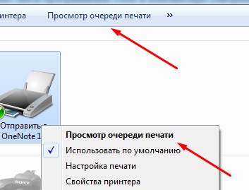
- В закладке «Принтер» выбираем пункт «Очистить очередь».
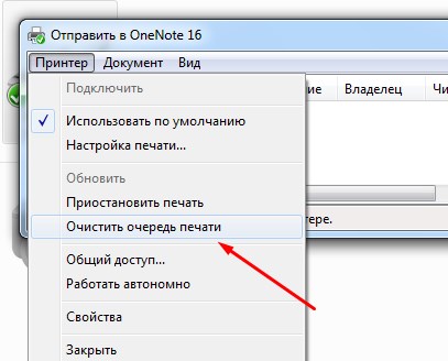
Принудительная очистка истории печати
Если приведенный выше способ не помог решить проблему, тогда выполняем следующие действия:
- Заходим в «Пуск», далее «Панель управления» — «Системы безопасности» и функция «Администрирование».
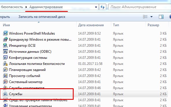
- В открывшемся окошке выбираем «Службы».
- Находим «Диспетчер печати» и нажимаем «Остановить». Таким образом вы остановите распечатку всех документов с компьютера.
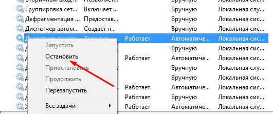
- Переходим в каталог: C:WINDOWSsystem32SpoolPrinters. Удаляем все файлы, отправленные на печать.
- Возвращаемся в «Службы» и возобновляем функцию печати в Диспетчере кнопкой «Запустить».
После этого история полностью очистится, и вы сможете быстро распечатать свои документы.
Источник
Содержание
- 1 Самые распространенные коды ошибок принтеров Kyocera
- 2 Код C7990
- 3 Способ №2. Замена чипа
- 4 Другие неисправности
- 5 Способ №1. Сброс счетчика страниц / тонера
- 6 Сброс ошибок у принтеров Kyocera своими руками
- 7 Способы решения проблемы
- 7.1 Сброс сообщения о неоригинальном тонере на Kyocera fs 1040
- 8
- 9
- 10
- 11
- 12
- 13
- 14 Значения мигания индикаторов
Самые распространенные коды ошибок принтеров Kyocera
Слово «ошибка» на английском языке будет «ошибка», поэтому большинство кодов начинаются с заглавной E.
Итак, какие ошибки могут возникать в принтерах Kyocera FS 1020MFP японского производства:
1.E-0002. Указывает, что картридж с тонером не подходит для региональных спецификаций. Вам нужно использовать другой картридж.
2.E-0003. Эта ошибка указывает на то, что память сканера заполнена. Будут доступны только самые последние отсканированные изображения. Чтобы сбросить ошибку E-0003, необходимо очистить память сканера. Для этого нажмите Стоп / Сброс.

Стирание памяти
3.E-0007. Значит, для печати не хватает чернил. Исправить код 07 просто — нужно добавить тонер.
4. При открытой задней или передней крышке МФУ Kyocera не работает и выдает код ошибки E-0008.
5. После печати или копирования большого количества бумаги (сто листов), если лоток не опорожняется, отображается сообщение об ошибке принтера Kyocera E-0009. Вам нужно удалить листы и нажать кнопку Старт, чтобы продолжить работу.
6. Иногда выдается код E-0012, что означает, что задача не может быть выполнена из-за нехватки оперативной памяти. Для решения этой проблемы необходимо изменить разрешение печати с 1200 на 600. Порядок действий описан в инструкции.
7. Когда появится код E-0014, загрузите бумагу нужного формата во входной лоток. Размер листов определяется драйвером принтера.
8. Если вы забыли подключить сетевой или USB-кабель, принтер отобразит код ошибки E-0015. Нужно нажать Stop / Reset, подключить кабель и снова нажать эту кнопку.

Замена картриджа с тонером
В японских принтерах Kyocera FS 1020MFP могут возникать ошибки, как описанные в предыдущем разделе, так и конкретные ошибки. Все коды можно найти в инструкции по эксплуатации.
Код C7990
Этот номер ошибки на моделях FS 1020MFP указывает на сигнал о переполнении тонера.

Ошибка C7990
Причин возникновения ошибки C7990 может быть три:
• неисправна плата PWB;
• неисправен датчик количества краски;
• бункер действительно полон — рекомендуется заменить барабан.

Барабан
В первых двух случаях необходимо обратиться в сервисный центр.
В третьем случае появления кода C7990, если ресурс барабана еще не исчерпан, можно очистить бункер для краски. Делают они это так:
1. Откройте переднюю крышку и выньте блок проявки.
2. Подойдите к барабану.
3. Осторожно откройте крышку бункера и удалите краску.
4. Соберите прибор в обратном порядке.
Как видите, ошибку принтера Kyocera C7990 легко устранить самостоятельно, а обращаться к специалистам нужно только тогда, когда карты действительно плохие.

Способ №2. Замена чипа
Альтернативный вариант сброса счетчика вручную — замена микросхемы. Вы можете заправлять картридж принтера KyoceraFS-1040 сколько угодно, но благодаря установке нового защитного чипа устройство не распознает замену расходного материала.

Ошибочно многие пользователи считают неисправностью, когда на корпусе принтера Kuoser 1040 горит красная кнопка с сообщением «Внимание» и принтер не печатает присланные ему документы. В этом материале мы рассмотрим, в каких случаях это происходит, что делать, как быстро все отремонтировать в домашних условиях, не обращаясь в сервисный центр. Инструкции применимы ко многим моделям Kyocera. Например, fs1040 взят из-за его популярности.
Другие неисправности
Также возможно появление таких кодов:
• C-F040. Вам нужно выключить и снова включить устройство, нажав кнопку питания.
• J-0511. Код указывает на то, что бумага застряла под задней крышкой. Инструкции описывают, как удалить бумагу в соответствующем разделе.
• ПФ. Принтер предложит вам добавить бумагу во входной лоток.

Как видите, принтеры японской компании Kyocera выходят из строя редко. Чаще всего ошибки возникают из-за неправильных или неосторожных действий. Вы можете исправить их самостоятельно, но если не уверены в своих силах, лучше проконсультироваться со специалистом.
Способ №1. Сброс счетчика страниц / тонера
Чтобы запустить принтер KyoceraFS-1040, просто сбросьте счетчик страниц / тонера, удерживая нажатыми кнопки «Отмена» и «GO».

Единственная проблема заключается в том, что удаление предупреждения принтера об использовании неоригинального картриджа может привести к аннулированию гарантии. Так как устройство записывает абсолютно все ошибки в «Журнал событий».
Сброс ошибок у принтеров Kyocera своими руками
Сбрасывая ошибки в принтерах Kyocera, необходимо понимать ряд мер, которые опытный пользователь может потенциально предпринять для восстановления и запуска печатающих устройств без обращения в сервисный центр.
Ошибка №
Это вызывает
Решение
E-0001
В принтер установлен совместимый картридж или повреждена микросхема расходных материалов. Проблему можно решить несколькими способами:
1 установите оригинальный картридж;
2 замена поврежденного чипа;
3 прошивки принтера — так что любой картридж можно устанавливать в принтер неограниченное количество раз;
4 сброс ошибки — держать нажатыми несколько секунд кнопки «Режим» и «Сброс».
E-0002
Регион используемого картриджа не соответствует техническим характеристикам принтера. Проблему можно решить несколькими способами:
1. Установите картридж, соответствующий региону принтера;
3 прошивки принтера.
E-0003
Память печатающего устройства заполнена. Распечатайте уже отсканированные документы или сбросьте операцию с помощью соответствующей кнопки.
E-0007
В картридже закончился тонер. Замените картридж на новый, оригинальный, совместимый или заправьте расходный материал.
E-0008
Одна из крышек принтера не закрыта. Закройте переднюю и заднюю крышки принтера до щелчка.
E-0009
Лоток для печати заполнен. Удалите отпечатанную бумагу и возобновите печать, нажав кнопку «Пуск».
E-0012
Память принтера заполнена. Измените разрешение печати до 600 dpi.
E-0014
Установлен формат бумаги, не поддерживаемый принтером. Замените бумагу листами совместимого размера.
Иногда функциональность принтера может быть ограничена на программном уровне.
Для расширения диапазона форматов рекомендуется обновить программное обеспечение печатающего устройства.
E-0015
1. В принтере нет питания.
2. Сетевой кабель не подключен.
3. На ПК нет драйверов. Проверьте целостность сетевого кабеля.
При необходимости установите драйвер.
E-0018
Выбранный файл отсутствует в очереди печати. Сбросьте операцию, нажав кнопку «Сброс». Затем выберите новый файл и продолжите печать.
E-0019
Формат печати не поддерживается принтером. Сбросьте операцию, нажав кнопку «Сброс».
J-0511
Бумага замята. Осторожно удалите оставшуюся бумагу из корпуса принтера.
ПФ
Во входном лотке нет бумаги. Загрузите бумагу во входной лоток и возобновите печать, нажав кнопку «Пуск».
Способы решения проблемы
Сброс сообщения о неоригинальном тонере на Kyocera fs 1040
Если вышеперечисленные варианты не сработали, то, скорее всего, проблема в самом картридже. Дело в том, что он оснащен датчиком уровня тонера и чипом, отслеживающим количество отпечатанных листов. Когда расходный материал заканчивается или, согласно чипу, он должен закончиться, печать блокируется до тех пор, пока он не будет заменен новым картриджем. Именно это и произошло в нашей ситуации.

Есть три варианта решения проблемы:
- Купите новый картридж и продолжайте его печатать. Это недешево.
- После каждой пополнения порошка следует заменять чип, который начнет отсчет количества распечатанных документов с нуля.
- Сбросить счетчик на микросхеме. Сделать это несложно, но делать это нужно каждый раз при включении устройства.
Инструкции по сбросу:
- Включите устройство.
- Подождите, пока двигатель остановится и красный свет не начнет мигать.
- Одновременно нажмите кнопки «Пуск» и «Отмена» на 5-7 секунд».

- Нажмите и удерживайте, пока красный и зеленый не начнут мигать по очереди.
- Ждем завершения процесса.
- Пытаюсь распечатать.
Значения мигания индикаторов
- Ничего не горит и уведомлений нет, значит, устройство полностью готово к работе.
- Медленное мигание кнопки означает, что в лотке нет бумаги или в картридже низкий уровень пыли.
- Индикатор мигает быстрее: внутри устройства застрял лист бумаги, лоток окончательной обработки заполнен, и распечатки невозможно вставить, вся память принтера заполнена и используются неоригинальные расходные материалы.
- Индикатор горит и не гаснет. Проверьте, закрыты ли крышки. Тонер для печати, возможно, уже закончился.
Если у вас возникли трудности с определением причин появления сообщения «Внимание», вы можете воспользоваться специальным программным обеспечением от инженеров компании — «Kyocera Client Tool». Эта утилита поможет вам более точно диагностировать проблему. Вы можете найти его на сайте компании или на диске с драйверами принтера.
Источники
- http://printergid.ru/neispravnosti/oshibki-kyocera
- https://dudom.ru/kompjutery/kyocera-1040-indikacija-oshibok/
- https://window-10.ru/ecosys-fs-1020mfp-oshibka-e7/
[свернуть]
Бумага застревает в большинстве случаев из-за поломки узла дуплекса. Самым эффективным решением проблемы, будет его замена.
При отправлении на печать в двустороннем режиме, лист не полностью выходит из печки и встаёт. Также слышен щелчок электромагнита, но лист аппарат не захватывает в обратном направлении для печати на второй стороне листа. Следовательно, застревает бумага в печке из-за неисправного дуплекса, обеспечивающего обратное движение бумажного носителя.
Ниже представлена инструкция по устранению проблемы и если у Вас застревает бумага в МФУ Kyocera, то Вы легко её устраните. Мануал подойдёт для следующих печатающих устройств:
- Kyocera FS-1028MFP;
- Kyocera FS-1128MFP;
- Kyocera FS-1030MFP;
- Kyocera FS-1035MFP;
- Kyocera FS-1130MFP;
- Kyocera FS-1135MFP.
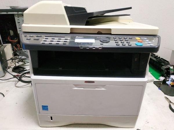
Перед началом устранения проблемы: «Застревает бумага в МФУ Kyocera при двусторонней печати», отключите устройство от сети питания и извлеките лоток подачи бумаги.
Откройте переднюю дверцу и извлеките блок проявки с тонер-картриджем.
Выньте из МФУ Kyocera драм-юнит. Он расположен за блоком проявки.
На задней стороне МФУ выкрутите винт крепления крышки.
Плоской отвёрткой отогните защёлки на крышке справа и слева, затем снимите крышку.
Откройте заднюю дверцу МФУ и аккуратно отогните правое ухо дверцы.
Снимите заднюю дверцу и переходите к следующему шагу по демонтажу корпуса для продолжения устранения проблемы: «Застревает бумага при двусторонней печати».
Демонтируем боковую крышку корпуса, аккуратно отгибая защёлки по периметру.
МФУ Kyocera FS-1028 без правой боковой крышки корпуса.
Снимаем крышку корпуса с противоположной стороны МФУ.
Отсоединяем разъёмы и шлейф на плате с маркировкой: A0628-B. У Вас маркировка данной платы может отличаться, это зависит от модели МФУ Kyocera.
Не забудьте освободить провода заземления от металлического основания!
Откручиваем 4 винта крепления платы.
Демонтируем плату выкрутив все винты крепления.
Далее нужно снять металлическое основание, на которое крепится плата, демонтированная на предыдущем шаге.
Выкручиваем все винты удерживающие металлический каркас. С помощью плоской отвёртки снимаем пластмассовую накладку (фото №5), под которой выкручиваем ещё один винт (фото №6).
Демонтируем металлический каркас.
Перед нами плата форматтера МФУ Kyocera, где необходимо отсоединить разъём, а также шлейф сканера, чтобы снять стол сканера с автоподатчиком.
Аккуратно отсоединяем шлейф сканера от платы форматтера.
Отсоединяем разъём от платы форматтера МФУ Kyocera.
С задней стороны МФУ откручиваем 2 винта удерживающих стол сканера.
Сдвигаем стол сканера немного назад до упора.
Демонтируем стол сканера, освобождая шлейф и провода с разъёмами через отверстия на верхней крышке корпуса станины МФУ.
Стол сканера вместе с автоподатчиком демонтирован и впереди последний этап решения проблемы при которой застревает бумага в режиме двусторонней печати.
Следующим шагом освобождаем белый провод из направляющих верхней части корпуса. Для этого аккуратно отогните прозрачную пластиковую накладку которая приклеена с задней стороны верхней части корпуса.
С левого бока МФУ Kyocera, со стороны кулера, необходимо снять накладную рамку.
Освобождаем все провода от направляющих.
Снимаем накладную рамку.
Спереди освобождаем дверцу верхней части корпуса от тяги, отжав стопора.
Теперь демонтируем верхнюю часть корпуса. Откручиваем винты сверху и по бокам МФУ. Отсоединяем разъём идущий на USB выход, не забывая освободить провод заземления. Также отсоединяем трёх-пиновый разъём.
Демонтируем оставшуюся, верхнюю часть корпуса.
Следующим шагом, нужно извлечь металлическую распорку.
Откручиваем по 2 винта с правого и левого бока, а также с задней стороны. Демонтируем распорку.
С платы форматтера МФУ Kyocera отсоединяем в правом нижнем углу очередной разъём.
Освобождаем плату форматтера от 5 винтов.
Полностью снимать главную плату не нужно, достаточно её немного отвести в сторону, чтобы был доступ к винтам крепления дуплекса — виновнику застревания бумаги.
Отсоединяем разъём с проводами идущими на электромагнит узла дуплекса.
Сдвинув плату форматтера откручиваем два винта крепления узла дуплекса.
С противоположной боковины проделываем тоже самое.
Для того чтобы извлечь дуплекс, слегка отгибаем с правого и с левого боков металлические стенки станины, затем демонтируем узел дуплекса.
Как видим, извлечённый дуплекс повреждён. Следовательно, это и есть причина того, что застревает бумага при двусторонней печати на МФУ Kyocera.
Внутренняя сторона боковой крышки узла дуплекса. Здесь сломано крепление флажка. Отсутствует второй выступ удерживающий флажок на своём месте.
Новый узел дуплекса, готовый к установке в МФУ Kyocera.
На этом всё! Теперь Вы знаете что делать если застревает бумага в МФУ Kyocera: FS-1028, FS-1128, FS-1030, FS-1035, FS-1130, FS-1135.

Прочтите раздел Руководства пользователя «Устранение застревания бумаги»
При застревании бумаги отображается сообщение о застревании, копирование или печать останавливаются. Оставьте выключатель питания в положении «Вкл
* Чтобы устранить застревание бумаги в универсальном лотке, аккуратно и медленно извлеките бумагу, застрявшую в универсальном лотке, чтобы сбросить состояние ошибки, откройте и закройте верхнюю и переднюю крышку.
* Для удаления застрявшей бумаги из лотка для бумаги извлеките или откройте лоток, аккуратно и медленно удалите частично поданную бумагу. Посмотрите, правильно ли загружена бумага. Если нет, загрузите ее еще раз. Закройте или надежно задвиньте кассету с бумагой обратно. Принтер прогреется и возобновит печать.
* Если бумага застряла внутри аппарата типа FS-1030/M2030/FS-1120/P2035, то удалите частично поданную бумагу из лотка. Затем откройте переднюю крышку, приподнимите и извлеките из аппарата узел проявки вместе с картриджем с тонером. Извлеките узел барабана из аппарата, удерживая за зеленые рычаги обеими руками. ПРИМЕЧАНИЕ: Барабан чувствителен к свету. Никогда не оставляйте узел барабана на свету более чем на пять минут. Если бумагу прижали валики, протяните ее вдоль нормального направления подачи. Возвратите узел барабана в нужное положение, совместив направляющие с обеих сторон со слотамив аппарате. Установите в аппарат узел проявки и картридж с тонером. Закройте переднюю крышку. Аппаратпрогреется и возобновит печать.
* Чтобы устранить застревание бумаги под задней крышкой, а так же в аппаратах типа FS-1040/FS-1020mfp, откройте заднюю крышку и удалите застрявшую бумагу, вытянув её. ОСТОРОЖНО: Термофиксатор, установленный внутри, очень горячий. Во избежание ожогов не дотрагивайтесь до него. Если бумага застряла внутри термофиксатора, откройте крышку термофиксатора и удалите бумагу, вытянув ее. Для устранения ошибки закройте заднюю крышку, откройте и закройте верхнюю (переднюю крышку. Аппарат прогреется и возобновит печать
* Чтобы устранить застревание бумаги в автоподатчике, поднимите автоподатчик и аккуратно извлеките лист по ходу его движения в процессе копирования/сканирования
— Не используйте повторно бумагу, которая уже застряла. — Если при извлечении застрявшая бумага порвалась, обязательно удалите из аппарата все обрывки. — Оставшиеся внутри аппарата клочки бумаги могут стать причиной последующего застревания. — Страница, на которую повлияло застревание бумаги, печатается повторно. — ОСТОРОЖНО: Узел фиксации чрезвычайно сильно нагревается. При работе в этом отсеке будьте особенно осторожны ввиду опасности получения ожогов
Обзор МФУ Kyocera ECOSYS M2040dn
Kyocera M2040DN Первое включение Двухстороннее копирование Добавление бумаги Замена тонера
Настройка сетевого сканирования по протоколу SMB
Kyocera Ecosys M2040dn Functions And Features Explained !
Характеристики МФУ Kyocera ECOSYS M2040dn
Устранение неисправностей > Устранение замятия бумаги
Вытяните кассету 1 наружу на себя до упора.
Извлеките застрявшую бумагу.
Задвиньте кассету 1 обратно.
• Не используйте повторно бумагу, которая уже была замята.
• Если при устранении замятия бумага надорвана, обязательно удалите из аппарата все обрывки.
Оставшиеся внутри аппарата фрагменты бумаги могут стать причиной последующего замятия.

Откройте переднюю крышку.

Извлечение замятой бумаги из кассеты 2, Извлечение замятой бумаги из кассеты 2 -34
- Изображение
- Текст
Вытяните кассету 2 наружу на себя до упора.
Задвиньте кассету 2 обратно.


Извлечение замятой бумаги из кассеты 3, Извлечение замятой бумаги из кассеты 3 -36
Вытяните кассету 3 наружу на себя до упора.
Задвиньте кассету 3 обратно.
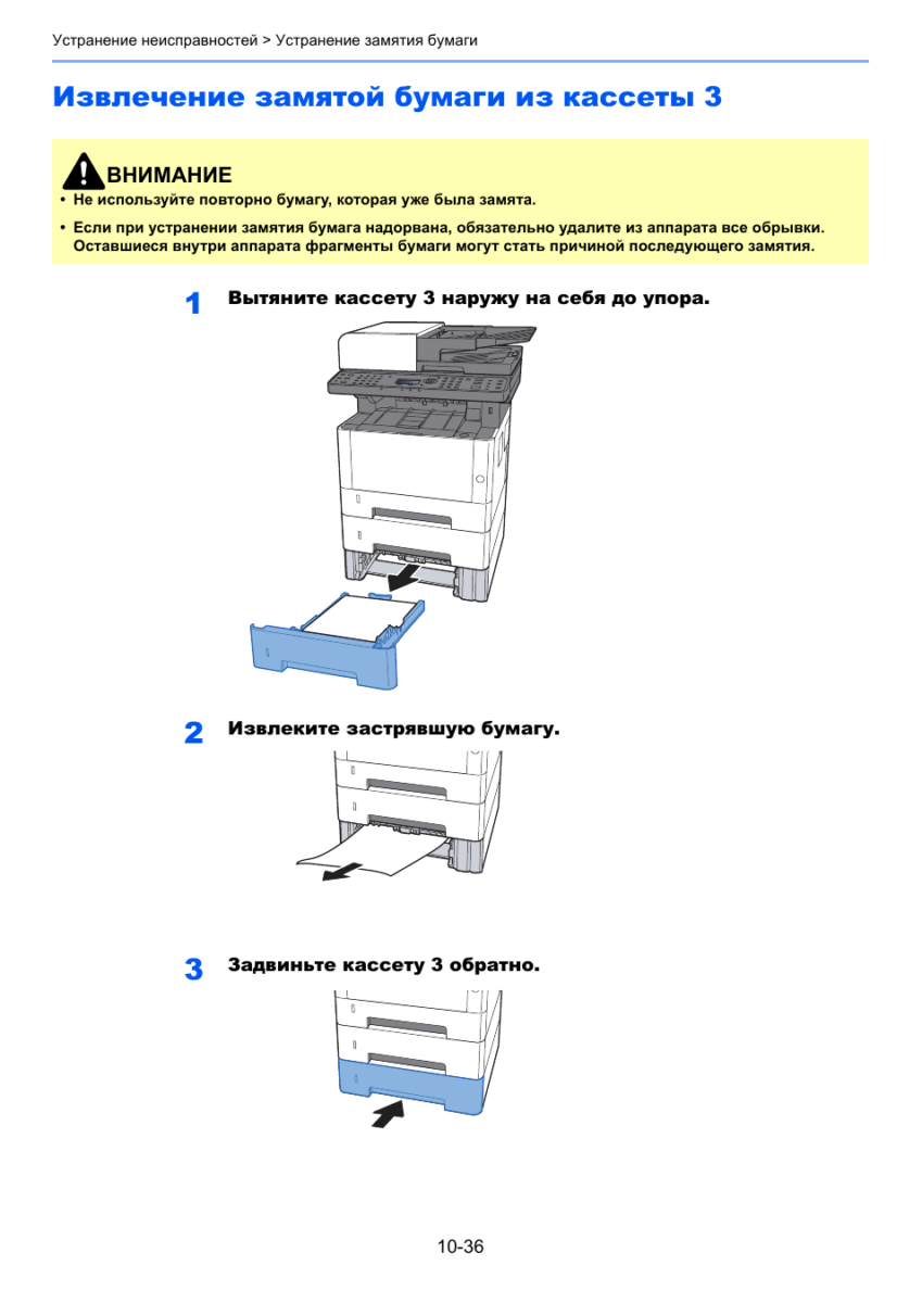
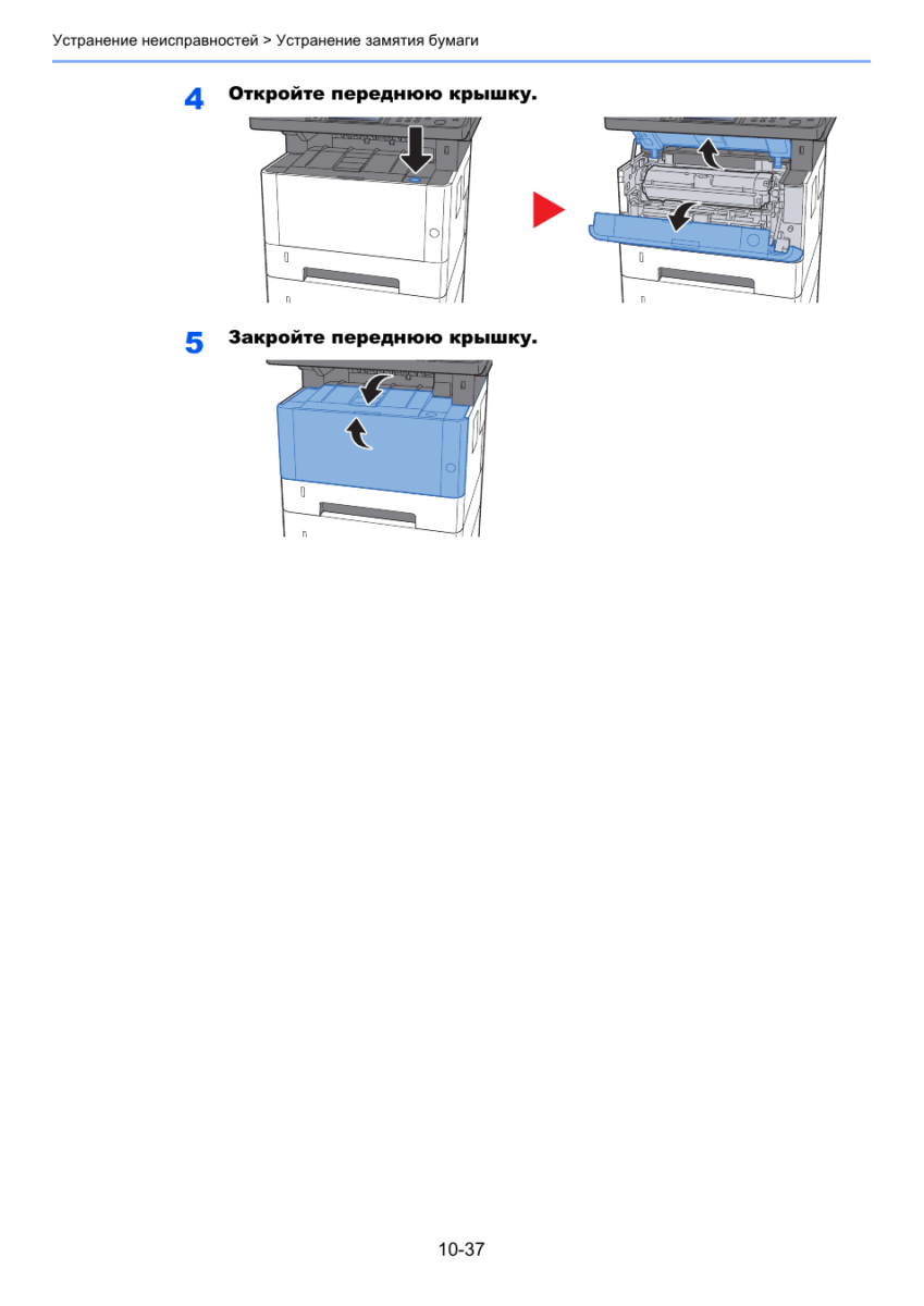
Извлечение застрявшей бумаги из
Извлеките всю бумагу.
Загрузите бумагу еще раз.
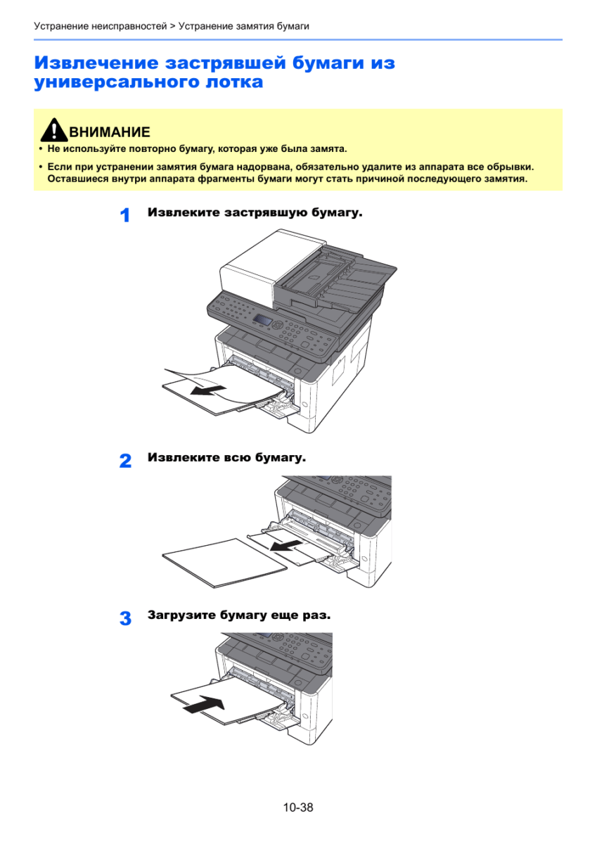
Извлечение застрявшей бумаги из аппарата, Извлечение застрявшей бумаги из аппарата -39
Извлечение застрявшей бумаги из аппарата
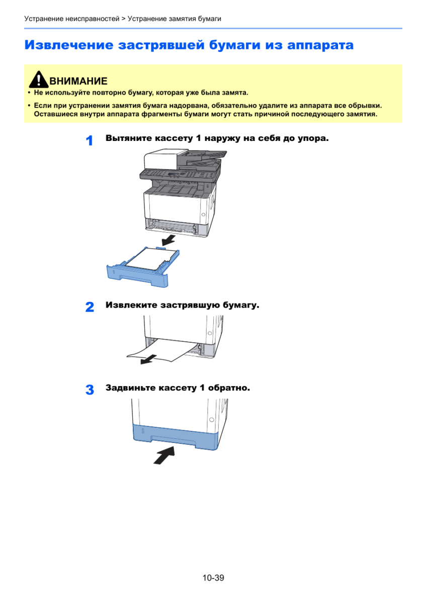
Приподнимите узел проявки вместе с контейнером с
тонером и извлеките из аппарата.
Положите узел проявки вместе с контейнером с тонером
горизонтально на чистую ровную поверхность.
Не прикасайтесь к узлу проявки, а также не подвергайте его ударным воздействиям. Это может привести к снижению качества печати.
Не кладите узел проявки вместе с контейнером с тонером на край поверхности.
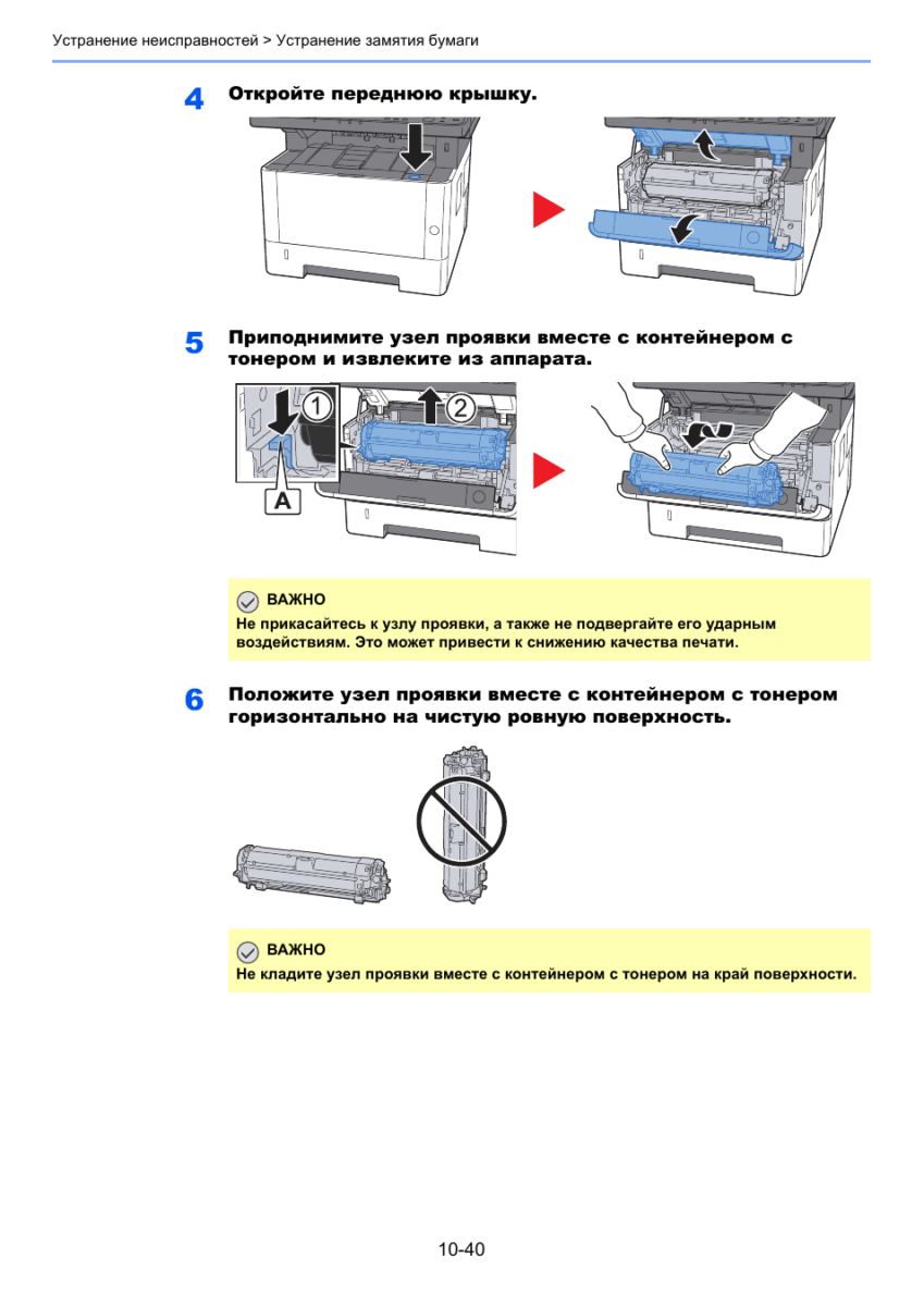
Достаньте барабанный блок из аппарата.
Положите барабан горизонтально на чистую ровную
Откройте крышку податчика (C).
• Термофиксатор, установленный внутри аппарата, очень горячий
избежание ожогов не дотрагивайтесь к нему.
• Не прикасайтесь к барабану, а также не подвергайте его ударным
воздействиям. Избегайте попадания прямых солнечных лучей или интенсивного освещения на барабан: это может привести к снижению качества печати.
Не кладите барабанный блок на край поверхности.