Коды ошибок Thermo Zanotti (Занотти)
ПРЕВЫШЕН ЛИМИТ СЕРВИСНОГО ОБСЛУЖИВАНИЯ (CТОЯНОЧНЫЙ РЕЖИМ).
·Аварийный сигнал информирует пользователя о необходимости произвести техническое обслуживание холодильного оборудования.
·При срабатывании аварийного сигнала обратитесь к ближайшему дилеру компании «ZANOTTI».
· ПРЕВЫШЕН ЛИМИТ СЕРВИСНОГО ОБСЛУЖИВАНИЯ
(ДОРОЖНЫЙ РЕЖИМ).
·Аварийный сигнал информирует пользователя о необходимости произвести техническое обслуживание холодильного оборудования.
·При срабатывании аварийного сигнала обратитесь к ближайшему дилеру компании «ZANOTTI».
·НИЗКОЕ ДАВЛЕНИЕ ВСАСЫВАНИЯ.
·Аварийный сигнал информирует пользователя о том, что производительность установки занижена.
·При устранении неисправности аварийный сигнал сбрасывается автоматически.
·При повторном срабатывании аварийного сигнала обратитесь к ближайшему дилеру компании «ZANOTTI».
·Аварийный сигнал информирует пользователя о том, что датчик низкого давления всасывания сработал повторно.
·Аварийный сигнал сбрасывается выключением и повторным включением установки.
·ВЫСОКОЕ ДАВЛЕНИЕ НАГНЕТАНИЯ.
·Аварийный сигнал информирует пользователя о том, что давление нагнетания хладагента чрезмерно высоко.
·При устранении неисправности аварийный сигнал сбрасывается автоматически.
·При повторном срабатывании аварийного сигнала обратитесь к ближайшему дилеру компании «ZANOTTI».
·Аварийный сигнал информирует пользователя о том, что датчик высокого давления нагнетания сработал повторно.
·Аварийный сигнал сбрасывается выключением и повторным включением установки.
·Аварийный сигнал информирует пользователя о том, что датчик низкого давления всасывания сработал повторно.
·Аварийный сигнал сбрасывается выключением и повторным включением установки.
·ЗАЩИТА ЭЛЕКТРОДВИГАТЕЛЯ.
·Аварийный сигнал сбрасывается выключением и повторным включением установки.
·При повторном срабатывании аварийного сигнала обратитесь к ближайшему дилеру компании «ZANOTTI».
·Аварийный сигнал информирует пользователя о том, что защита электродвигателя сработала повторно.
·Аварийный сигнал сбрасывается выключением и повторным включением установки.
·НЕИСПРАВЕН ДАТЧИК ТЕМПЕРАТУРЫ ВОЗВРАТНОГО ВОЗДУХА.
·Аварийный сигнал сбрасывается выключением и повторным включением установки.
·При повторном срабатывании аварийного сигнала обратитесь к ближайшему дилеру компании «ZANOTTI».
·ТЕМПЕРАТУРА ВОЗВРАТНОГО ВОЗДУХА ВЫШЛА ЗА ВЕРХНИЙ ПРЕДЕЛ ЗАДАННОЙ ТЕМПЕРАТУРЫ.
·Аварийный сигнал является информационным.
·ТЕМПЕРАТУРА ВОЗВРАТНОГО ВОЗДУХА ВЫШЛА ЗА НИЖНИЙ ПРЕДЕЛ ЗАДАННОЙ ТЕМПЕРАТУРЫ.
·Аварийный сигнал является информационным.
PAB ·НИЗКОЕ НАПРЯЖЕНИЕ АККУМУЛЯТОРНОЙ БАТАРЕИ.
·Аварийный сигнал информирует пользователя о низком напряжении аккумуляторной батареи автомобиля.
·Аварийный сигнал является информационным и появляется только при работе в «дорожном режиме».
·НИЗКОЕ НАПРЯЖЕНИЕ АККУМУЛЯТОРНОЙ БАТАРЕИ.
·Аварийный сигнал информирует пользователя о низком напряжении аккумуляторной батареи автомобиля.
·При срабатывании аварийного сигнала на экране высвечивается изображение аккумуляторной батареи.
·При стабилизации напряжения аварийный сигнал сбрасывается автоматически.
·При повторном срабатывании аварийного сигнала обратитесь к ближайшему дилеру компании «ZANOTTI».
·ВСТРЕЧНАЯ НАГРУЗКА.
·Аварийный сигнал информирует пользователя о том, что одновременно активированы «дорожный режим» и «стояночный режим».
·При срабатывании аварийного сигнала на экране высвечивается индикация «дорожного режима» и «стояночного режима».
ВНИМАНИЕ: Во избежание появления аварийного сигнала, убедитесь, что ключ зажигания автомобиля находиться в нулевом положении.
Nol · НЕТ СВЯЗИ МЕЖДУ БЛОКОМ УПРАВЛЕНИЯ И КОНТРОЛЛЕРОМ.
·При появлении данного аварийного сигнала и для устранения неисправности обратитесь к ближайшему дилеру компании «ZANOTTI».
· КЛАВИАТУРА РАЗБЛОКИРОВАНА.
· Предупреждение появляется при разблокировании клавиатуры.
· Разблокирование и блокировка клавиатуры осуществляется одновременным нажатием и удерживанием клавиш «вверх/вниз».
· КЛАВИАТУРА ЗАБЛОКИРОВАНА.
·Аварийный сигнал появляется при нажатии любой клавиши на пульте управления.
Компания «ZANOTTI S.p.A.» благодаря многолетнему опыту сегодня стала синонимом неоспоримого качества, надежности и безопасности в области производства холодильного оборудования для пищевой промышленности. Основная деятельность компании направлена на оптимизацию использования «холода» в процессе замораживания и хранения продукции агропродовольственного сектора, во время сушки и созревания колбасных изделий и сыров, при консервации зерновых холодом в силосных башнях и хладообеспечении рефрижераторного транспорта.
Инструкция по изменению параметров электронной панели управления типа ZANOTTI Electronic (CAREL IR32)
Инструкция по изменению параметров электронной панели управления DB»O»
Инструкция по изменению параметров электронной панели управления SB (для машин у которых сер.номер заканчивается на “I”)
Инструкция по изменению параметров электронной панели управления GM/GS
Описание работы POWERFROST EWPK 2000 ZANOTTI
Инструкция по изменению параметров электронной панели управления AS-AC-SB-TP SP»C»-SP»O»-DB»O»
Устройство программирующее циклы оттайки — Модель 13102/24
Системы управления и контроля уровня масла для холодильных систем и тепловых насосов (EN 378-1)
Монитор напряжения фирмы «EMIREL»
Инструкция по изменению параметров электронной панели управления регулятора CAREL32
Тел.: +7 (495) 410-96-90, многоканальный
E-mail: coldholod@bk.ru
Москва и московская область
Время работы: пн-вс 7:00-23:00
Прием заявок: круглосуточно
It is possible to adjust some parameters to create an
alarm to remind the operator to arrange for
maintenance. Two different alarms can be displayed
by the in-cab controller:
1.
SEE
Standby maintenance hours
exceeded.
2.
Ser warning that Road
mode maintenance hours
exceeded
The parameters to set the intervals are in the
programming menu, at the end of the list.
Total run-time hour counters
•
«EtM» total STAND-BY running hours
counter (display only)
•
«rtM» total
counter (display only)
These counters display the overall run-time hours of
the machine in road and stand-by operation.
To display these values, access the parameters menu
and select the above parameters.
Partial running hours counters
•
«EtP»
partial STAND-BY run-time hour
counter
«rtP»
partial ROAD run-time hour
•
counter
These counters are used to generate service alarms
according to service intervals set by means of the
parameters:
•
«SEE» stand-by service interval
«Ser»
road mode service interval
•
•
Service alarms are displayed when the value of the
parameter rtP or EtP reaches the limit given by the
parameters SEE or SEr. If the value of the SEE or SEr is
set to 0, the alarm display is disabled and
corresponding counter EtP or rtP remains at 0.
The maintenance alarms SEE or SEr blink on the cab
warning
that
ROAD
running
command module and alternate with the temperature; no
acoustic signal is activated.
Press any key to reset the alarm. However, the alarm will
be displayed every time the unit will be switched on until
the following reset procedure is performed:
Resetting partial run-time counters
1. access the program menu by pressing the
<PRG> button
2. select the parameter Etp or rtp by means
of the arrows keyspressing the <SET>
button makes the parameter value blink
3. hold the <DOWN ARROW> button for 3
seconds and the value resets to 0
4. press the <SET> button to move to the
next parameter
NOTE: All the parameters listed above are expressed in
units of 10 hours (example: SEr = 80 means 800 hours).
NOTE: For full parameter table. See Section 7
hours
26
Автотема
Автотема – схемы, статьи, руководства по ремонту автомобилей.
Автотема
Автотема – схемы, статьи, руководства по ремонту автомобилей.
Меню
-
12.09.2016, 10:38
#1

Новичок
 Сброс сервисного интервала Zanotti
Прошу помощи!Как сбросить сервисный интервал на Zanotti fz219
-
13.10.2016, 12:45
#2
Новичок
 Сообщение от teploled1

сбросить сервисный интервал на Zanotti fz219
через меню защищенного доступа,на словах,это сложно,ошибка же информационная на работу рефа не влияет
Похожие темы
-
Ответов: 25
Последнее сообщение: 14.11.2017, 06:51
-
Ответов: 0
Последнее сообщение: 09.10.2016, 22:05
-
Ответов: 14
Последнее сообщение: 27.11.2011, 23:52
-
Ответов: 4
Последнее сообщение: 23.12.2010, 20:58
-
Ответов: 3
Последнее сообщение: 21.03.2010, 10:38
Социальные закладки
Социальные закладки
-

Google

Ваши права
- Вы не можете создавать новые темы
- Вы не можете отвечать в темах
- Вы не можете прикреплять вложения
- Вы не можете редактировать свои сообщения
- BB коды Вкл.
- Смайлы Вкл.
- [IMG] код Вкл.
- [VIDEO] код Вкл.
- HTML код Выкл.
Правила форума
- Manuals
- Brands
- Zanotti Manuals
- Air Conditioner
- zer0
- Use and maintenance instructions
-
Contents
-
Table of Contents
-
Bookmarks
Quick Links
I
GB
ES
RU
F
D
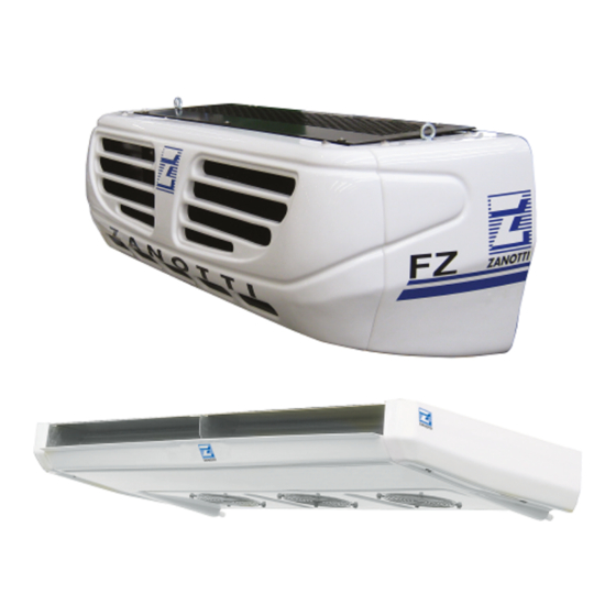
zer 0°- FZ
MANUALE USO E MANUTENZIONE
USE AND MAINTENANCE INSTRUCTIONS
NOTICE DE MODE D’EMPLOI ET D’ENTRETIEN
GEBRAUCHS – UND WARTUNGSHANDBUCH
MANUAL DE USO Y MANUTENCIÓN
Related Manuals for Zanotti zer0
Summary of Contents for Zanotti zer0
-
Page 1
zer 0°- FZ MANUALE USO E MANUTENZIONE USE AND MAINTENANCE INSTRUCTIONS NOTICE DE MODE D’EMPLOI ET D’ENTRETIEN GEBRAUCHS – UND WARTUNGSHANDBUCH MANUAL DE USO Y MANUTENCIÓN… -
Page 2
The ranges zer0° and FZ are the result of a simple and tested design and reliability. The purchase price and low cost of operation and management make this group ideal for installation on vehicles transporting with small / medium size. -
Page 3
INDEX 1. IMPORTANT NOTES AND SAFETY IDENTIFICATION Nameplate Summary table plates and stickers 3. PRODUCT LOADING 4. OPERATION Road mode operation Stand-by mode operation Temperature regulation Defrosting Heating function Multi-temperature operation 5. DESCRIPTION OF CONTROL Display Operations 5.2.1 Switching on and off 5.2.2 Set point setting 5.2.3… -
Page 4
1. IMPORTANT NOTES AND SAFETY When installing and using the unit please follow the recommendations listed here below. Installation shall be carried out in strict compliance with the diagrams and instructions supplied by the manufacturer. Damages due to improper connections are excluded. … -
Page 5
For safe use of the unit, we suggest: ATTENTION Do not use water or steam when cleaning as the electrical components may be damaged. Keep condenser and evaporator clean. Stand-by operation in enclosed places: ensure good ventilation to the condenser. … -
Page 6
IDENTIFICATION 2.1 Nameplate Each unit Zanotti Transblock is identified by a sticker. On the plate they are given the plant model, serial number and other information. For any problem, refer to the information on the data plate and note the plant model and serial number before calling your service personnel. -
Page 7
2.2 Summary table plates and stickers Refrigerant Condensate drain line Attention: hot or cold parts Attention: switch off before operating on the unit. Attention: danger of electrocution Connect this cable to a circuit breaker, never to the main line directly. Direction of rotation Colours of supply cable wires Attention –… -
Page 8: Product Loading
Product loading Proper air circulation inside the insulated cell is essential to maintain the quality of the goods during transport. This ensures a uniform temperature distribution within the whole cell. If the air can not circulate freely around the load, you may create zones of heat or ice formations.
-
Page 9: Operation
4. OPERATION 4.1 Road mode operation The control unit recognizes that the unit is in road mode when the ignition key of the vehicle is turned on. Battery unit Direct drive unit The unit is powered directly from the battery and An open-type compressor is driven by the engine the alternator of the vehicle on which it is of the vehicle, while the vehicle battery directly…
-
Page 10
Defrosting During cooling, the air releases moisture that accumulates gradually between the evaporator fins until freeze and block the passage of air which progressively reducing the efficiency of the system and subsequently causing damage. For this reason, regularly it does a defrost cycle in order to melt the ice accumulated and drain externally water. The control unit manages autonomously and periodically the beginning and the end of the defrosts. -
Page 11
Description of control 5.1 Display 5.1.1 Single temperature version 1. ON/OFF BUTTON: to switch on/off the unit (press 3 seconds). The red LED lights up when the unit is on. 2. SET button: to set the work set point of the unit. When the LED is on, setting is enabled. 3. -
Page 12
5.1.2 Multi-temperature version 1. ON/OFF BUTTON 1: to switch on/off the evaporator of compartment 1 (press 3 seconds). The red LED lights up when the unit is on. 2. SET BUTTON 1: to set the work set point of the evaporator of compartment 1. When the LED is on, setting is enabled. -
Page 13: Switching On And Off
Operations The following instructions apply generally to both versions of the display. The only difference concerns the presence of dedicated keys for each compartment, respectively marked by numbers 1 and 2. 5.2.1 Switching on and off Road mode: Stand-by mode: The start of the motor vehicle by the ignition key Make sure that the supply voltage corresponds to that automatically enables the road mode, marked with the…
-
Page 14: Set Point Setting
5.2.2 Set point setting: Push the botton the display shows the current value of the temperature in flashing red and the yellow icon push the buttons to se the desired value. push again or waiting 10” to save the new value. 5.2.3 Manual defrosting As mentioned the control unit operates autonomously defrosts.
-
Page 15
5.3.3 List of alarms and messages The following is the complete list of all the signals and alarms that may occur; also we outlined some of the possible causes and remedies can be implemented also by the user, remembering that if the problem persists you should contact an authorized service center. -
Page 16: Rst Reset
Icon Alarm Description Possible causes Possible remedies Maintenance When is reached a set number of operation hours, are generated alarms SEE(SEE) stand-by maintenance or SEr(SEr) road mode maintenance, alternating with temperature display; This display can be temporarily reset by pressing any key and will recur after switching off and the following restart of the unit.
-
Page 17: Maintenance
MAINTENANCE Proper maintenance is crucial for durability of the machine in operation and optimum performance and to ensure the security provided by the manufacturer. For reliable use in time of the group it is necessary to make a limited number of routine maintenance operations. For this follow the instructions of the booklet Maintenance 0MDL178 (provided with the documentation supplied with the unit) to which we give the maintenance schedule based on hours of operation: Service Road mode program (Abbreviation…
-
Page 18: Type Description
SERVICE If necessary, you should contact your dealer in the first instance to identify the nearest service center. Alternatively you can contact your local Zanotti distributor; the list of national distributors is available on our website at the following link: http://www.zanotti.com/it/zanotti-nel-mondo…
-
Page 19: How To Order Spare Parts
Zanotti designs its parts because they meet extreme demands of the refrigeration systems in vehicles. Invest in quality and reliability allows to supply spare parts that guarantee a longer life and increased maintenance intervals. The best way to ensure that your Zanotti unit remains efficient and reliable is to keep 100% Zanotti. Contact your dealer.
-
Page 20
Zanotti S.p.A. Via M.L. King, 30 — 46020 Pegognaga (MN) Italy Tel. 0376.5551 Fax 0376.536554 Info@zanotti.com www.zanotti.com…
This manual is also suitable for:
Fz
It is possible to adjust some parameters to create an
alarm to remind the operator to arrange for
maintenance. Two different alarms can be displayed
by the in-cab controller:
1.
SEE
Standby maintenance hours
exceeded.
2.
Ser warning that Road
mode maintenance hours
exceeded
The parameters to set the intervals are in the
programming menu, at the end of the list.
Total run-time hour counters
•
«EtM» total STAND-BY running hours
counter (display only)
•
«rtM» total
counter (display only)
These counters display the overall run-time hours of
the machine in road and stand-by operation.
To display these values, access the parameters menu
and select the above parameters.
Partial running hours counters
•
«EtP»
partial STAND-BY run-time hour
counter
«rtP»
partial ROAD run-time hour
•
counter
These counters are used to generate service alarms
according to service intervals set by means of the
parameters:
•
«SEE» stand-by service interval
«Ser»
road mode service interval
•
•
Service alarms are displayed when the value of the
parameter rtP or EtP reaches the limit given by the
parameters SEE or SEr. If the value of the SEE or SEr is
set to 0, the alarm display is disabled and
corresponding counter EtP or rtP remains at 0.
The maintenance alarms SEE or SEr blink on the cab
warning
that
ROAD
running
command module and alternate with the temperature; no
acoustic signal is activated.
Press any key to reset the alarm. However, the alarm will
be displayed every time the unit will be switched on until
the following reset procedure is performed:
Resetting partial run-time counters
1. access the program menu by pressing the
<PRG> button
2. select the parameter Etp or rtp by means
of the arrows keyspressing the <SET>
button makes the parameter value blink
3. hold the <DOWN ARROW> button for 3
seconds and the value resets to 0
4. press the <SET> button to move to the
next parameter
NOTE: All the parameters listed above are expressed in
units of 10 hours (example: SEr = 80 means 800 hours).
NOTE: For full parameter table. See Section 7
hours
26