-
8/2/2019 ZF 2
1/92
-
8/2/2019 ZF 2
2/92
ZF
.
,
-
8/2/2019 ZF 2
3/92
HP 502 C / HP 592 C / HP 602 C
. . . . . . . . . . . . . . . . . . . . . . . . . . . . . . . .
. . . . . . . . . . . . . . . . . . . . . . . . . . . . . . . . 5 .
. . . . . . . . . . . . . . . . . . . . . . . . . . . . . . . . . .
. . 6. . . . . . . . . . . . . . . . . . . . . . . . . . . . . . . .
. . . . . . . . . . . . 6. . . . . . . . . . . . . . . . . . . . . . . . . . . . . . . .
. . . . . . . . . . . . . . . . . . . . . . . . . 9. . . . . . . . . . . . . . . . . . . . . . . . . . . . . . . .
. . . . . . . . . . . . . . . . . . . . . . . 11. . . . . . . . . . . . . . . . . . . . . . . . . . . . . . . .
. . . . . . . . . . . . . . . . . . . . . 12 . . . . . . . . . . .
. . . . . . . . . . . . . . . . . . . . . . . . . . . . . . . . . .
. . . . 15. . . . . . . . . . . . . . . . . . . . . . . . . . . . . . . .
. . . . . . . . . . . . . . 19Ecomat . . . . . . . . . . . . . . . . . . . . . . . . . . . . .
. . . . . . . . . . . . . . . . 20. . . . . . . . . . . . . . . . . . . . . . . . . . . . . . . .
. . . . . . . . . . . . . 221 . . . . . . . . . . . . . . . . . . . . . . . . . . . . . . .
. . . . . . . . . . . . . . . . . . . . . 1-11.1 . . . . . . . . . . . . . . . . . . . . . . . . . . . . . .
. . . . . . . . . . . . . . . . . . 1-11.2 . . . . . . . . . . . . . . . . . . . . . . . . . . . . . .
. . . . . . . . . . . . . . . . . . . . . . . . . . . 1-11.3 . . . . . . . . . . . . . . . . . . . . . . . . . . . . . .
. . . . . . . . . . . . . . . . . . . . . . . . . . . . . . .
1-11.4 . . . . . . . . . . . . . . . . . . . . . . . . . . . . . .
. . . . . . . . . . . . . . . . . . . . . . . 1-21.5 . . . . . . . . . . . . . . . . . . . . . . . . . . . . . .
. . . . . . . . . . . . . . . . . . . . . . . . . 1-21.6 . . . . . . . . . . . . . . . . . . . . . . . . . . . . . .
. . . . . . . . . . . . . . . . . . . . . . . . . . . . 1-21.7 . . . . . . . . . . . . . . . . . . . . . . . . . . . . . .
. . . 1-21.8 . . . . . . . . . . . . . . . . . . . . . . . . . . . . . .
. . . . . . . . . . . . . . 1-31.9 . . . . . . . . . . . . . . . . . . . . . . . . . . . . . .
. . . . . . . . . . 1-31.10 , . . . . . . . . . . 1-3
1.11 . . . . . . . . . . . . . . . . . . . . . . . . . . . . . .
. . . . . . . . . . 1-42 . . . . . . . . . . . . . . . . . . . . . . . . . . . . . . .
. . . . . . . . . . . . . . . . . . . . . . . . . . . . . . . . . .
. . . 2-12.1 . . . . . . . . . . . . . . . . . . . . . . . . . . . . . .
. . . . . . . . . . . . . . . . . . . . . . . . . . . . . 2-12.2 — . . . . . . . . . . . . . . . . . . . . . . . . . . . . .
. . . 2-32.3 . . . . . . . . . . . . . . . . . . . . . . . . . . . . . .
. . . . . . . . . . 2-42.4 . . . . . . . . . . . . . . . . . . . . . . . . . . . . . .
. . . . . . . . . . . . . . . . . . . . . . . . . . 2-52.5 . . . . . . . . . . . . . . . . . . . . . . . . . . . . . .
. . . . . . . . . . . . . . . . . . 2-6 -
8/2/2019 ZF 2
4/92
HP 502 C / HP 592 C / HP 602 C
3 . . . . . . . . . . . . . . . . . . . . . . . . . . . . . . .
. . . . . . . . . . . . . . . . . . . . . . . . . 3-13.1 . . . . . . . . . . . . . . . . . . . . . . . . . . . . .
3-13.2 1P01 138 153 . . . . . . . . . . . . . . . . . . . . . . . .
. . . . . . . . . . . . . . . . . . . 3-23.3
ZF Testman
4 . . . . . . . . . . . . . . . . . . . . . . . . . . . . . . .
. . . . . . . . . . . . . . . . . . . . . . . . . . . . . . . . . .
. . . . 4-1NBS 4149 700 026/1 . . . . . . . . . . . . . . . . . . . . . . .
. . . . . . . . . . . . 4-1NBS 4149 700 026/2. . . . . . . . . . . . . . . . . . . . . . .
. . . . . . . . . . . . . . 4-36029 729 041/1-4 . . . . . . . . . . . . . . . . . . . . . . . .
. . . . . . . . . . . . . . . . . . 4-5 6029 729 040 . . . . . . .
. . . . . . . . . . . . . . . . . . . . . . . . 4-136029 729 072 . . . . . . . . . . . . . . . . . . . . . . . . . .
. . . . . . . . . . . . . . . . . 4-15 -
8/2/2019 ZF 2
5/92
,
ZF Friedrichshafen AG,
ZF.
ZF
.
—
.
, ZF ,
.
ZF Friedrichshafen
AG, , :
1.
2. , ,
3. ZF,
.
HP 502 C / HP 592 C / HP 602 C
-
8/2/2019 ZF 2
6/92
: ,
ZF,
.
. .
ZF
,
.
.
:
, , ,
. .
,
.
, , ., , ( ).
.
,
.
!
,
.
, , .
.
!
HP 502 C / HP 592 C / HP 602 C
-
8/2/2019 ZF 2
7/92
ZF. .
.
.
,
,
.
, Loctite,
, .
.
.
,
.
,
,
,
.
, ,
, .
.
,
.
.
, ,
,
,
.
HP 502 C / HP 592 C / HP 602 C
-
8/2/2019 ZF 2
8/92
,
(, ).
. 85 C
120 .
.
*,
-.
,
.
.
,
.
a)
*.
b)
d)
.
()
.
e) 60 %
* (, Aralub
HL2 Aral Spectron FO 20
DEA).
f) , ,
40 50 C (
).
.
*
,
.
(, Loctite)
-.
, .
HP 502 C / HP 592 C / HP 602 C
X
-
8/2/2019 ZF 2
9/92
HP 502 C / HP 592 C / HP 602 C
, ZFN 148
,
DIN 912, DIN 931, DIN 933,
DIN 960, DIN 961 ,
DIN 934.
()
8.8, 10.9 12.9,
8, 10 12.
:
,
.
—
.
.
() ()
8.8 10.9 12.9 8.8 10.9 12.9
8 10 12 8 10 12
M 4 2,8 4,1 4,8 M 8 x 1 24 36 43
M 5 5,5 8,1 9,5 M 9 x 1 36 53 62
M 6 9,5 14 16,5 M 10 x 1 52 76 89
M 7 15 23 28 M 10 x 1,25 49 72 84
M 8 23 34 40 M 12 x 1,25 87 125 150
M 10 46 68 79 M 12 x 1,5 83 122 145
M 12 79 115 135 M 14 x 1,5 135 200 235
M 14 125 185 215 M 16 x 1,5 205 300 360
M 16 195 280 330 M 18 x 1,5 310 440 520
-
8/2/2019 ZF 2
10/92
HP 502 C / HP 592 C / HP 602 C
DIN 908, 910 7604
DIN 7604 , . , .
, DIN 908 DIN 910, . : 5, ZFN 148-1 : DIN 7604 : ( )
, .
DIN 7643
,
.
, .
:
5, ZFN 148-1
: 9SMnPb28K DIN 1651
: (
)
,
.
(DIN 908, 910, 7604)
/
M 8 x 1 20 10
M 10 x 1 25 / 30* 15 / 20*
M 12 x 1,5 35 25
M 14 x 1,5 35 25
M 16 x 1,5 40 30
M 18 x 1,5 50 35
M 20 x 1,5 55 45
M 22 x 1,5 60 / 80* 50 / 65*M 24 x 1,5 70 60
M 26 x 1,5 80 / 105* 70 / 90*
M 27 x 2 80 70
M 30 x 1,5 100 / 130* 90 / 130*
M 30 x 2 95 85
(DIN 7643)
4 — 5 M 8 x 1 20 — 25
6 M 10 x 1 25 — 35
8 M 12 x 1,5 30 — 40
10 M 14 x 1,5 35 — 40
12 M 16 x 1,5 45
15 M 18 x 1,5 50
18 M 22 x 1,5 60
-
8/2/2019 ZF 2
11/92
HP 502 C / HP 592 C / HP 602 C
— ZF .
:
0750 199 001 Spectron FO 20
WEVO-L100
0666 790 017
0671 190 016 8420
.
TE-ML14
-
8/2/2019 ZF 2
12/92
01.
02.
( ) nT nAbt.
03.
14×1,5
04.
22×1,5
05.
R = . 67
20 C
R = 1080
40
20C
35
50
0,5 0,7
1P01 138 153
6008 006 002
,
1X56 138
149 / 1X56 138 150
.
74
.
.1350
.
.
.
.
HP 502 C / HP 592 C / HP 602 C
-
8/2/2019 ZF 2
13/92
08.
09.
10.
11.
6
12.
12
13.
42×2
14.
o
0,7 1,4
35
14 15
6
60
90 100
12
.
.
.
156 136 824.
.
.
.
1X56 136 471.
.
HP 502 C / HP 592 C / HP 602 C
-
8/2/2019 ZF 2
14/92
-
8/2/2019 ZF 2
15/92
HP 502 C / HP 592 C / HP 602 C
. — .
156 136 471
1
1
1X56 136 824
1
2
1P01 136 670
0 25
10×1
1
3
1P01 137 856
0 10
1
4
-
8/2/2019 ZF 2
16/92
HP 502 C / HP 592 C / HP 602 C
. — .
1X56 138 149
(
1X56 138 150)
1
6
1X56 138 150
(
1X56 138 149)
1
7
1X56 103 755
(
1X56 136 512)
1
8
1X56 136 512
1
9
-
8/2/2019 ZF 2
17/92
. — .
HP 502 C / HP 592 C / HP 602 C
1P01 138 153
1
11
6008 006 002
68-
1
12
6008 208 003
Testman Windows 95, 98 NT
,
:
6008 308 901 Test-
man (1)
6008 308 600 DPA 04 I (2)
1
Windows 95,
98 NT
:
6008 208 004
6008 208 003,
13
3
2
4
5
-
8/2/2019 ZF 2
18/92
HP 502 C / HP 592 C / HP 602 C
. — .
6008 307 001
MobiDig 2001
1
ZF15
0501 301 068
EPD1
1
ZF
16
6008 298 029
Plug-In EPD1
1
ZF
17
0501 211 103
ISO EPD1
1
18
-
8/2/2019 ZF 2
19/92
123DN
R
67
9
17
2
8
10
11
12
14
15
1613
3
5
1 4
013190
013190
HP 502 C / HP 592 C / HP 602 C
-
8/2/2019 ZF 2
20/92
HP 502 C / HP 592 C / HP 602 C
ZF-Ecomat 2 4
013468
1 2 4 5 6 7 9 10 11 12 13
26 25 24 23 22 21 20 19 18 17 16 15 14013468
-
8/2/2019 ZF 2
21/92
HP 502 C / HP 592 C / HP 602 C
ZF-Ecomat 2 5 6
013467
1 2 4 5 6 7 8 9 10 11 12 13
013467
26 25 24 23 22 21 20 19 18 17 16 15 14
-
8/2/2019 ZF 2
22/92
HP 502 C / HP 592 C / HP 602 C
HP 502 HP 592 HP 602
4 4149 002 . . . 4149 052 . . . 4149 062 . . . 2,81 — 1,00
4 4149 006 . . . 4149 056 . . . 4149 066 . . . 3,43 — 1,00
5 4149 001 . . . 4149 051 . . . 4149 061 . . . 2,81 — 0,805 4149
003 . . . 4149 053 . . . 4149 063 . . . 3,43 — 0,836 4149 004 . . . 4149 054 . . . 4149 064 . . . 3,43 — 0,59
Ecomat 2 NBS
/ A B1 B2 D E F1 F2
4 i = 2,81 1,00
i = 3,43 1,00
1 2 3 4
Ecomat 2 NBS
/ A B2 C D E F1 F2
5 i = 2,81 0,80
i = 3,43 0,83
6 i = 3,43 0,59
Ecomat 2 NBS
/ A B2 C D E F1 F2
5 i = 2,81 0,80
i = 3,43 0,83
6 i = 3,43 0,59
Ecomat 2 NBS
/ A B1 B2 D E F1 F2
4 i = 2,81 1,00
i = 3,43 1,00
*
NBS *1 2 1 4. Gang
-
8/2/2019 ZF 2
23/92
1.
1.1
: . ( ). ( ) ZF 4139 298 936.
—
. 1 000 50
ATF ZFN 13015, TE-ML 14, 14 / 14D:
. 30 000
*. 20 000
, , . . 1 000
1 .
ATF — ZFN 13015, TE-ML 14, 14B:
. 60 000
*. 45 000
, , . . 2 000
1 2 .
ATF ZFN 13015, TE-ML 14, 14:
. 120 000
*. 90 000
, , . . 3 000
HP 502 C / HP 592 C / HP 602 C
-
8/2/2019 ZF 2
24/92
011576
150
130
50
80
110
c
VDO
001683
1.4
.
.
.
.
.
.
.
. .
-, . .
.
1.5
.
80 90 C.
1.6
,
. 1 3
10
!
HP 502 C / HP 592 C / HP 602 C
( )
( )
-
8/2/2019 ZF 2
25/92
1.9
:
.
,
.
, .
1.10 ,
HP 502 C / HP 592 C / HP 602 C
011577
} . 30 C
011577
} (n= 0)
1.8
:
N
()
. 30 C
3 5
.
,
.
.
-
8/2/2019 ZF 2
26/92
009871
011576
1.11
.
.
(. . 2.1).
(50 )
(23 ), . . 2.1.
.
.
. 10 3 .
4 3 .
(. . 1.8).
.
(80 90 C).
HP 502 C / HP 592 C / HP 602 C
(50 )
(23 )
-
8/2/2019 ZF 2
27/92
011578
011579
2.
2.1
1
(1) , 1.11.
. .
:
!
2 (2).
3 (1).
.
. .
:
!
4
( 0750 131 003).
!
!
HP 502 C / HP 592 C / HP 602 C
1
1
2
1
-
8/2/2019 ZF 2
28/92
7 (1) (2).
8 (1).
9 4
(2).
: 23
HP 502 C / HP 592 C / HP 602 C
011578
1
010483
2
1
2
-
8/2/2019 ZF 2
29/92
011580
011581
2.2
1 (1)
.
2 2
8 (2).
3 (1)
(2).
4 2
8×22.
HP 502 C / HP 592 C / HP 602 C
1
2
1
2
-
8/2/2019 ZF 2
30/92
011583
011584
2.3
1 2
.
2 .
3 2
8 (1).
4 (1)
.
5 .
6
8×55 (1).
HP 502 C / HP 592 C / HP 602 C
1
1
-
8/2/2019 ZF 2
31/92
011584
011587
2.4
1 (1)
2.3.
2 2
8 (2)
.
3 2
8 (1)
.
4 (1)
HP 502 C / HP 592 C / HP 602 C
2 1
1
-
8/2/2019 ZF 2
32/92
011589
011590
2.5
1 2
.
2 .
3
(1).
.
: 35
4 2
TG
HP 502 C / HP 592 C / HP 602 C
1
-
8/2/2019 ZF 2
33/92
011592
011775
2.6
1 (1) .
2 (1)
.
,
.
, .
3 (2)
.
4 (4)
(1),
HP 502 C / HP 592 C / HP 602 C
1
1
2
4
-
8/2/2019 ZF 2
34/92
011598
012901
5 ,
(1)
.
6
156 138 149 (1)
(2).
: 9,5
7 (3)
(4).
8 (2)
.
9
HP 502 C / HP 592 C / HP 602 C
1
1
2
34
-
8/2/2019 ZF 2
35/92
011779
011780
10 156 138 150
.
: 9,5
11
c.
0,5 0,7 .
:
b = d
d+a= S
:
c = 52,6 b = 51,3
= 0,6 (0,5 0,7 )
:
HP 502 C / HP 592 C / HP 602 C
c
-
8/2/2019 ZF 2
36/92
12 (1)
(2).
(3)
(4).
13
(1) .
14
645 (2).
: 9,5
15
,
HP 502 C / HP 592 C / HP 602 C
011776
2
134
011775
1
2
-
8/2/2019 ZF 2
37/92
012902
012903
HP 502 C / HP 592 C / HP 602 C
2.6.1
1
2.6.
2
.
, .
3 .
. .
,
.
(6029 201 6)
(1).
(2) , , .
: 6029 201 6 (48) = 46,40
WTB = 1,96150,00
6029 201 652 150,00
6029 201 651 100,00
6029 201 650 75,00
6029 201 649 57,60
6029 201 648 46,40
6029 201 647 37,40
2
1
-
8/2/2019 ZF 2
38/92
011775
4 ,
, .
HP 502 C / HP 592 C / HP 602 C
-
8/2/2019 ZF 2
39/92
011578
011579
2.7
1
2.1.
2
(1) .
3
.
.
, .
4 .
!
HP 502 C / HP 592 C / HP 602 C
1
-
8/2/2019 ZF 2
40/92
016073
016072
5 ,
ZA 5 (1)
.
6 (1)
.
7
.
HP 502 C / HP 592 C / HP 602 C
1
1
-
8/2/2019 ZF 2
41/92
011579
9 (1)
.
.
10
8×60 .
: 23
11
1 .
.
.
12
1
HP 502 C / HP 592 C / HP 602 C
011603
1
-
8/2/2019 ZF 2
42/92
HP 502 C / HP 592 C / HP 602 C
-
8/2/2019 ZF 2
43/92
011579
011607
2.8
1
2.7.
2 42×2 (1).
3
(1) .
HP 502 C / HP 592 C / HP 602 C
1
-
8/2/2019 ZF 2
44/92
011783
5 (4) (1),
(2) (3).
6
(1).
7
HP 502 C / HP 592 C / HP 602 C
1
011776
4
321
HP 502 C / HP 592 C / HP 602 C
-
8/2/2019 ZF 2
45/92
011784
011785
8 156 138 149
(1).
: 9,5
9 (1)
(2).
10 (3)
.
11
HP 502 C / HP 592 C / HP 602 C
1
1
2
3
HP 502 C / HP 592 C / HP 602 C
-
8/2/2019 ZF 2
46/92
011779
12 156 138 150
.
: 9,5
13
c.
0,6 0,8 .
.
:
c b = d
d + a = S
: c = 52,6
b = 50,9
= 0,7 (0,6 0,8 )
HP 502 C / HP 592 C / HP 602 C
011780
c
HP 502 C / HP 592 C / HP 602 C
-
8/2/2019 ZF 2
47/92
011610
14 (1)
(2).
(3)
(4).
15
6×45 (1).
: 9,5
16
(2) .
17 42×2
.
HP 502 C / HP 592 C / HP 602 C
1
2
011776
2
134
HP 502 C / HP 592 C / HP 602 C
-
8/2/2019 ZF 2
48/92
011578
18 2.7.
19
1.9.
.
.
20
1.
HP 502 C / HP 592 C / HP 602 C
HP 502 C / HP 592 C / HP 602 C
-
8/2/2019 ZF 2
49/92
013480
011624
2.9
.
1 ;
.
2
8 (1)
Kostal.
3
2.7.
HP 502 C / HP 592 C / HP 602 C
1
HP 502 C / HP 592 C / HP 602 C
-
8/2/2019 ZF 2
50/92
4
(1)
(2)
.
(3).
.
5
(4) (5).
6
, (1)
(2)
.
7 39 8,
, .
!
HP 502 C / HP 592 C / HP 602 C
015825
2134
5
015826
1
2
HP 502 C / HP 592 C / HP 602 C
-
8/2/2019 ZF 2
51/92
011630
011629
8 8 .
, .
, , . , , .
9 , . :
Kostal () .
. . 18 .
.
!
10
HP 502 C / HP 592 C / HP 602 C
HP 502 C / HP 592 C / HP 602 C
-
8/2/2019 ZF 2
52/92
11 8 (39 ),
,
:
30 8×43 (1)
9 M8x35 (2)
9
.
.
: 23
12
, (1)
.
(2)
. .
13 (3)
.
.
14 ,
015827
1
2
015828
1
2
3
HP 502 C / HP 592 C / HP 602 C
-
8/2/2019 ZF 2
53/92
011607
011624
16
8×20 .
: 23
17
2.8,
.
18
2.7.
HP 502 C / HP 592 C / HP 602 C
-
8/2/2019 ZF 2
54/92
015829
015830
2.10
2.7 2.9.
(1)
.
1 6 (1)
.
,
.
2 6 (1)
1
1
1
HP 502 C / HP 592 C / HP 602 C
-
8/2/2019 ZF 2
55/92
015832
015833
3 ,
(1)
(3) (2).
4 ,
630 (1).
: 9,5
1
2
3
1
1
1
HP 502 C / HP 592 C / HP 602 C
-
8/2/2019 ZF 2
56/92
015833
015835
5 616 (1).
6 ,
.
!
.
:
4149 043 005
= 15,7+/0,5
7
616 (1)
1
X
HP 502 C / HP 592 C / HP 602 C
-
8/2/2019 ZF 2
57/92
015831
015830
9
630 (1).
: 9,5
10
.
11
630 (1), .
: 9,5
,
.
1
2
X
1
HP 502 C / HP 592 C / HP 602 C
-
8/2/2019 ZF 2
58/92
011635
011636
2.11
1 (1).
2
.
3 .
: 35
1
HP 502 C / HP 592 C / HP 602 C
-
8/2/2019 ZF 2
59/92
011638
011639
2.12 /
1
(1).
,
.
2
12.
,
.
3 (1),
.
4
!
1
1
HP 502 C / HP 592 C / HP 602 C
-
8/2/2019 ZF 2
60/92
012273
011642
5
.
.
6 (1)
156 136 824 ,
.
.
,
.
7
(.
1
HP 502 C / HP 592 C / HP 602 C
-
8/2/2019 ZF 2
61/92
001 654
15-1
001654
011645
156 136 824:
151
.
9
.
10
100 110 C.
110 C,
.
.
.
11
!
HP 502 C / HP 592 C / HP 602 C
-
8/2/2019 ZF 2
62/92
011647
011648
13
1230
(WEVOL100
WEVOCHEMIE),
.
: 60
.
14
156 136 471
12 ,
.
!
HP 502 C / HP 592 C / HP 602 C
-
8/2/2019 ZF 2
63/92
011650
011651
2.13
,
:
1
, .
.
101 136 670
( 25 )
101 136 856
( 10 )
1 = P H
2 = P D1
3 =
P D2
4 = PD6 PD7*
5 = PR3
6 =
P RR3
* (4) = PD6* (4) = PD6
PD7=
2
.
3
.
4
12
35
6
HP 502 C / HP 592 C / HP 602 C
-
8/2/2019 ZF 2
64/92
:
A = B =
1400
:
1 = PH
2 = P
D1(PD1 = = 10 )3 = PD2
4 = PD6 PD7** = PD6* =
PD6 PD7= 5 = PR36 =
PRR37 = tl
nmot = WK =
: , , ZF.
.
N
N D
N
.
..
N
N D
WK
nmot
(1
)
700
550
20002500
700
550
20002500
tl(C)
20 40
20 40
20 40
20 40
80 90
80 90
80 90
PH()
7 15
7 15
18 21
10 12
7 15
7 15
16 20
PD1()
40,3
0,2 1,0 2
40,3
40,3
40,3
0,2 1,0 2
40,3
PD2()
4,0 5,5
4,0 5,5
6,0 8,5
6,0 8,5
3,0 4,5
3,0 4,5
6,0 8,5
PD6/D7()
0,8 1,8
0,8 1,8
1,8 2,5
1,8 2,8
0,1 0,8
0,1 0,8
1,8 2,5
PR3/PRR3()
A
M 10×1 M 10×1 M 10×1 M 10×1 M 10×1
4 5*/6*
* , ZF.
. 20002500 80 90 10 12 40,3 6,0 8,5
7
.
N
321
1,8 2,5
20002500
nmot tl PH PD1 PD2 PD6/D7 PR3/PRR3
B
M 10×1 M 10×1 M 10×1 M 10×1 M 10×1
4 5*/6*7 321
HP 502 C / HP 592 C / HP 602 C /
-
8/2/2019 ZF 2
65/92
3
3.1
25, 55, 68 EST
68-
6008 006 002
(1)
*6008 199 001
(1) (2) (3)
68- — 55-
*6008 004 024 (2)
*6008 004 025 (3)
EST
55- — 25-
6008 004 026
6008 004 027
55-
1P01 137 834
/ HP 502 C / HP 592 C / HP 602 C
-
8/2/2019 ZF 2
66/92
—
—
6029 201 652 150,00
6029 201 651 100,00
6029 201 650 75,00
6029 201 649 57,60
6029 201 648 46,40
6029 201 647 37,40
6029 201 646 31,60
6029 201 645 26,10
6029 201 644 22 10
— .
.
,
.
3.2 1P01 138 153
a) Kostal
Kostal
!
( )
( )
,
( )
.
!
HP 502 C / HP 592 C / HP 602 C /
-
8/2/2019 ZF 2
67/92
b) :
, .
.
:
.
.
B14
.
Y17
A A 13
Y16
B1 B 12
Y15
B2 C 11
Y14
D D 22
Y13
E E 24
Y12
F F 19
Y11
G / F2 G 6
Y18
WK WK 9
D1-.
Y20 B11
n . . nAB 2
( )
. 67 4 20C
. 67 4 20C
. 67 4 20C
. 67 4 20C
. 67 4 20C
. 67 4 20C
. 67 4 20C
. 67 4 20C
. 850 100 20C
* 1 96 150 k
. 8,6 0,5
20C
A4
Bez.
. 67 4 20C
RET K 18
D1
D1 10
Y19
—
RET 8
/ HP 502 C / HP 592 C / HP 602 C
-
8/2/2019 ZF 2
68/92
Temp. 2*Rt 2*Rt (min) 2*Rt (max)
[C] [Ohm] [Ohm] [Ohm]
-20 957796 896080,6 1023353,4
-15 720948 676412 768108
-10 547652 515240,8 581880,2
-5 419668 395880 444708
0 324282 306690,8 342746
5 252580,6 239476,2 266295,4
10 198235,8 188407 20849415 156760,6 149700,6 164443,6
20 124765,8 119130 130615,8
25 99991 95685,8 104448
30 80649,2 77343 84063,2
35 65448,2 62896,4 68076,4
40 53425,2 51446,4 55457,8
45 43857 42316 45435,8
50 36197,6 34992,8 37428,8
55 30031,2 29086 30994,860 25040 24296 25796,4
65 20978,6 20391,2 21574
70 17657 17192,4 18127
75 14927,6 14559,2 15299,2
80 12674 12381,4 12968,2
85 10804,8 10572,4 11038,2
90 9248 9063 9433
95 7945,8 7775 8117100 6852 6694,8 7010
105 5929,8 5785,4 6075,4
110 5149,4 5017 5283,2
115 4486,4 4365 4609,4
120 3921,6 3810 4034,2
125 3438 3336 3541,6
130 3023,2 2929,8 3118,4
135 2666,2 2580,6 2753,6
140 2357,8 2279,4 2438,2145 2090,8 2018,8 2164,6
150 1858,8 1792,8 1926,8
DKS 4261 (2*in Reihe)
NTC
B14
Thermometrics DKS 4261
2
20 C 150 C
/
. 2*Rt 2*Rt (.) 2*Rt (.)
[C] [] [] []
DKS 4261 (2* )
HP 502 C / HP 592 C / HP 602 C
-
8/2/2019 ZF 2
69/92
-
8/2/2019 ZF 2
70/92
ZF
ZF Testman
-
8/2/2019 ZF 2
71/92
. . . . . . . . . . . . . . . . . . . . . . . . . . . . . . . .
. . . . . . . . . . . . . . . . . . . . . . . . . . . . . . . . . .
4. . . . . . . . . . . . . . . . . . . . . . . . . . . . . . . .
. . . . . . . . . . . . . . 5ZF Testmann . . . . . . . . . . . . . . . . . . . . . . . . . .
. . . . . . . . . . 6K . . . . . . . . . . . . . . . . . . . . . . . . . . . . . . .
. . . . . . . . . . . . . . . . . . . . . . . . . 6Testman . . . . . . . . . . . . . . . . . . . . . . . . . . . .
. . . . . . 7. . . . . . . . . . . . . . . . . . . . . . . . . . . . . . . .
. . . . . . . . . . . . . . . . . . . . 8. . . . . . . . . . . . . . . . . . . . . . . 9
. . . . . . . . . . . . . . . . . . . . . . . . . . . . . . . .
. 9DPA 04 I . . . . . . . . . . . . . . . . . . . . . . . . . . . .
. . . . . . . . . . . . . . . . . . . . . . . 10DPA 04 I . . . . . . . . . . . . . . . . . . . . . . . . . . . .
. . . . . . . . . . . . . . . 11COM . . . . . . . . . . . . . . . . . . . . . . . . . . . . . .
. . . . . . . . . . . . . . . . . . . . . . . . 11Testman . . . . . . . . . . . . . . . . . . . . . . . . . . . .
. . . . . . . . . . . . . . . . . . . . . . . 12. . . . . . . . . . . . . . . . . . . . . . . . . . . . . . . .
. . . . . . . . . . . . . . . . . . . . . 13Produktmenue . . . . . . . . . . . . . . . . . . . . . . . . . .
. . . . . . . . . . . . . . . . . . . . . . . . . . . . . 14Produktmenue . . . . . . . . . . . . . . . . . . . . . . . . . .
. . . . . . . . . . . . . . . . . . . . . . . . 14. . . . . . . . . . . . . . . . . . . . . . . . . . . . . . . .
. . . . . . . . . . . . . . . . . . . . . . . . 15. . . . . . . . . . . . . . . . . . . . . . . . . . . . . . . .
. . . . . 15. . . . . . . . . . . . . . . . . . . . . . . . . . . . . . . .
. . . . . . . . . . . . . . . . . . . . . . 16ZF Testman
-
8/2/2019 ZF 2
72/92
, ZF Friedrichshafen AG
.
ZF
.
—
.
,
ZF
,
.
ZF Friedrichshafen
AG, , :
1.
2. , ,
3.
ZF,
.
ZF Testman
-
8/2/2019 ZF 2
73/92
: ,
ZF,
.
.
.
ZF
,
.
.
:
, , ,
. .
,
.
/ ZF Testman
-
8/2/2019 ZF 2
74/92
ZF Testman
/
,
. .
/
ZF Testman
:
Testman
6008 308 901
ZF Testman Testman
T t
-
8/2/2019 ZF 2
75/92
Testman
Windows 95, Windows 98 u Windows
NT. ( Windows NT
.)
1. Test-
man 1 ( )
2. Start
(Desktop Windows) Ausfhren
.
3. Ausfhren
.
4. Durchsuchen
.
5. (, ).
6. .
7. estman/setup
.
estman .
estman
. ,
.
1 estman
: 6008 308 901
1
015917
ZF Testman
Testman
-
8/2/2019 ZF 2
76/92
Testman.
ZF ISO ManProperties.
COM .
,
Z
.
COM.
015911
1.
Testman.
2. .
3. Programm
Beim Beenden schlieen
.
4. bernehmen
OK
ZF Testman
-
8/2/2019 ZF 2
77/92
1.
(, ).
2. Start
(Desktop Windows) Ausfhren
.
3. Ausfhren
.
4. Durchsuchen
.
5. (, ).
6. .
7.
Install c d.
8.
.
.
1
: 6008 308 900
ZF.
1
015916
1
2
Testman:
1 (1)
DPA 04 I (3) RS 232 (2).
2 ISO SAE (4)
(ISO 9141 /
SAE JI708) DPA 04 I (3)
.
DPA 04 I ZF Testman
-
8/2/2019 ZF 2
78/92
DPA 04 I
DPA 04 I V-24
RS232, ISO 9141 SAE JI708.
RS232 DPA 04 I
.
ISO 9141 SAE JI708 DPA 04 I .
ISO SAE
.
DPA 02/03
( ISO ).
DPA 04 I :
1. ISO
.
2. SAE
.
3.
MobiDig 2001/200
SAE.
1. L-Ltg
,
L.
2. Data
,
.
3. Ubatt
,
(12 24 ).
SAE
KL15ECU.
4. UPRG AUS :
.
EIN :
.
Testman
AUS .
,
.
5. KL15ECU
ISO
.
DPA 04 I ZF Testman COM
DPA 04 I flash-prom ( DPA 04 I ,
-
8/2/2019 ZF 2
79/92
p (
), Testman.
,
, Testman.
1. Testman.
2. DPA 04 I.
3. DPA 04 I
ISO SAE.
4. (C D) GDS3000/dpaload.
5. dpa4.bat.
DPA
04 I
Testman.
1 .
015908
COM 1.
,
.
1.
.
2. GDS3000dpaloadbload166.cfg.
3.
(. ).
4. .
Testman ZF Testman
-
8/2/2019 ZF 2
80/92
Testman Development C: GDS3000 apps Ecomat.app
Start Testman Developmen…Testman Developmen…
File PAL2Application Help
012290
Testman
012290/013809/013810/013811
Testman
1.
Testman .
2. Testman :
File ()
Testman
8. ffnen .
9. .
10. ffnen .
11. ffnen ,
RUN Pal2Application .
ZF Testman
-
8/2/2019 ZF 2
81/92
RUN Pal2Application
RUN
Enter
Weiter
ZF Service!
Produktmenue !
Testman Development C: GDS3000 apps Ecomat.app
Start Testman Developmen…Testman Developmen…
File PAL2Application Help
012290
/ ZF Testman
Testman Development C: GDS3000 apps Ecomat.app
-
8/2/2019 ZF 2
82/92
Enter
Weiter
!
!
Start Testman Developmen…Testman Developmen…
File PAL2Application Help
012290
Reparaturhilfe ( )
Tips () Diagnose ()
Test Ein.-Ausgnge ( )
Fahrzeugkonfiguration ( )
ZF Service Telefonverzeichnis( ZF )
Produktmenue ( )
Reparaturhilfe ( )
, ,
, ,
,
Tips ()
Diagnose ()
:
,
.
.
:
:
, . .
ZF Testman /
Testman Development C: GDS3000 apps Ecomat.app
-
8/2/2019 ZF 2
83/92
Enter
Weiter
!
!
Start Testman Developmen…Testman Developmen…
File PAL2Application Help
012290
Wartung ()
Anziehdrehmomente ( )
Spezialwerkzeuge/Prfgerte ( /)
Instandsetzung ()
Schalt- und Anschlussplne( )
Drcke ()
Elekt. Messwert ( )
Zurck zum Menue ( )
Reparaturhilfe ( )
Wartung ()
,
ZF, , ,
Anziehdrehmomente ( )
Schalt- und Anschlussplne (
)
Drcke ()
Elekt. Messwert
( )
ZF Testman
DPA 04 I
-
8/2/2019 ZF 2
84/92
Windows 95 / 98 Windows NT 4.0
Pentium 90
16 / NT 4.0 32
20
3 1/2
COM 1 COM 2
12 24
0 50 C
20 +60C
10 90%
801000 AM 1 80%
4
8
HP 502 C / HP 592 C / HP 602 C NBS 4149 700 026/1
AUSFUEHRUNG
HAUPTDRUCKVENTIL
MIT DRUCKABSENKUNG
DETAIL X
NA
i = 2.81 BIS 1.0
3.43 BIS 1.0
TO
A B1 B2 D E F1 F2
P NEUTRAL
RUECKWAERTS
REVERSE
VERSION2 NEBENATRIEBE MOEGLICH
4 GANG
4 GEAR
-
8/2/2019 ZF 2
85/92
A
B1
C
D
E
F1
X
WK
D2
P
WK
B
D1
P
P
A8
D2
D5D6
R1
R2
D8
D7
R3
A2
A1
D4
B1 = INNERE KOLBENFLAECHE KUPPLUNG B
B 2 = AEUSSERE KOLBENFLAECHE KUPPLUNG B
F 1 = AEUSSERE KOLBENFLAECHE BREMSE F
F 2 = INNERE KOLBENFLAECHE BREMSE F
1. GANG1st GEAR
2. GANG
2nd GEAR
3. GANG
3rd GEAR
4. GANG4th GEAR
INNER PISTON FACE CLUTCH B
OUTER PISTON FACE CLUTCH B
OUTER PISTON FACE BRAKE F
INNER PISTON FACE BRAKE F
MAIN PRESSURE VALVEWITH PRESSURE REDUCER
2 NEBENATRIEBE MOEGLICH
PTO’S CAN BE FITTED
DROSSELDRUCKVENTIL
THROTTLE PRESSURE
VALVE
PRIMAER-
PUMPE
PRIMARY PUMP
SAUGFILTER
SUCTION FILTER
HAUPTDRUCK-
VENTIL
MAIN PRESSURE
VALVE
WANDLER-
SICHERHEITS-
VENTIL
CONVERTER
SAFETY VALVE
WANDLER-GEGENDRUCK-
VENTIL
CONVERTER
COUNTER-
PRESSURE
VALVE
WAERMETAUSCHER
OIL COOLER
SPEICHER
ACCUMULATOR
SCHMIERDRUCK-
VENTIL
LUBRICATING
PRESSURE VALVE
KUEHLER-
UMSCHALT-
VENTIL
COOLER
CHANGEOVER
VALVE
RETARDER
TEMP.-
MESS-
STELLE
TEMPERATUR
SWITCH
SENSOR
RETARDER-
REGELVENTIL
RETARDER
CONTROL VALVEF2
F
C B2
B2
WANDLER-
ENTLEERVENTIL
D1
D8
R3
D2
RR3
P
F1-VENTIL
F2-VENTIL
F1
i = 2.81 BIS 0.8
3.43 BIS 0.59
/ 3.43 BIS 0.83
TO
TO
A B2 C D E F1 F2
NEUTRAL
RUECKWAERTSREVERSE
1. GANG
1st GEAR
2. GANG
2nd GEAR
3. GANG
3rd GEAR
4. GANG4th GEAR
5. GANG
5th GEAR
6. GANG6th GEAR
D9
5 — &. 6 GANG
5 — & 6 GEAR
CONVERTER-
PURGE VALVE
011867
4-1
HP 502 C / HP 592 C / HP 602 C NBS 4149 700 026/2
MIT DRUCKABSENKUNG
HAUPTDRUCKVENTIL
AUSFUEHRUNG
DETAIL X
NA
P
TO
3.43 BIS 1.0
i = 2.81 BIS 1.0
A1
B2
B D E1
F2
F
REVERSE
RUECKWAERTS
4 GANG
4 GEAR
-
8/2/2019 ZF 2
86/92
A
B1
C
D
E
F1
X
WK
D2
P
WK
B
D1
P
P
A8
D2
D5D6
R1
R2
D8
D7
R3
A2
A1
D4
WITH PRESSURE REDUCER
MAIN PRESSURE VALVE
VERSION2 NEBENABTRIEBE MOEGLICH
PTO’S CAN BE FITTET
VALVE
THROTTLE PRESSURE
DROSSELDRUCKVENTIL
PRIMARY PUMP
PUMPE
PRIMAER-
SUCTION FILTER
SAUGFILTER
VALVE
MAIN PRESSURE
VENTILHAUPTDRUCK-
SAFETY VALVE
CONVERTER
VENTIL
SICHERHEITS-
WANDLER-
VALVE
PRESSURE
COUNTER-
CONVERTER
VENTIL
GEGENDRUCK-
WANDLER-
OIL COOLER
WAERMETAUSCHER
ACCUMULATOR
SPEICHER
PRESSURE VALVE
LUBRICATING
VENTIL
SCHMIERDRUCK-
VALVE
CHANGEOVER
COOLER
VENTIL
UMSCHALT-
KUEHLER-
RETARDER
SENSOR
SWITCH
TEMPERATUR
STELLE
MESS-
TEMP.-
CONTROL VALVERETARDER
REGELVENTILRETARDER-
P
F2
F
C B2
B2
G
D1
D8
R3
D2
RR3
P
F1 VENTIL
F2 VENTIL
D9
= INNERE KOLBENFLAECHE BREMSE F2F
= AEUSSERE KOLBENFLAECHE BREMSE F1
F
= AEUSSERE KOLBENFLAECHE KUPPLUNG B2
B
= INNERE KOLBENFLAECHE KUPPLUNG B1
B
NEUTRAL
1st GEAR
1. GANG
2nd GEAR
2. GANG
3rd GEAR
3. GANG
4th GEAR
4. GANG
INNER PISTON FACE BRAKE F
OUTER PISTON FACE BRAKE F
OUTER PISTON FACE CLUTCH B
INNER PISTON FACE CLUTCH B
NEUTRAL NBS *
*
* = REDUZIERTER DRUCK
*
A2
B C D E1
F2
F
NEUTRAL
REVERSE
RUECKWAERTS
1st GEAR
1. GANG
2nd GEAR
2. GANG
3rd GEAR
3. GANG
4th GEAR
4. GANG
5th GEAR
5. GANG
NEUTRAL NBS
*
WANDLER-
ENTLEERVENTIL
CONVERTER-
PURGE VALVE
i = 2.81 BIS 0.8
3.43 BIS 0.59
/ 3.43 BIS 0.83
TO
TO
6. GANG
6th GEAR
5 — &. 6 GANG
5 — & 6 GEAR
011938
4-3
HP 502 C / HP 592 C / HP 602 C EST 46C 6029 729 041/1
-
8/2/2019 ZF 2
87/92
015812
4-5
HP 502 C / HP 592 C / HP 602 C EST 46C 6029 729 041/2
-
8/2/2019 ZF 2
88/92
015811
4-7
HP 502 C / HP 592 C / HP 602 C EST 47C 6029 729 041/3
-
8/2/2019 ZF 2
89/92
015810
4-9
HP 502 C / HP 592 C / HP 602 C EST 47C 6029 729 041/4
-
8/2/2019 ZF 2
90/92
015809
4-11
HP 502 C / HP 592 C / HP 602 C EST 46/47 C 6029 729 040
-
8/2/2019 ZF 2
91/92
015813
4-13
HP 502 C / HP 592 C / HP 602 C EST 46/47 C, 6029 729 072
-
8/2/2019 ZF 2
92/92
015808
4-15
Руководство по эксплуатации
ZF-Ecomat
HP 500 HP 590 HP 600
ZF-Ecomat 2/ZF-Ecomat 2 plus
HP 502 HP 592 HP 602
HP 502C HP 592C HP 602C для городских, маршрутных и междугородных автобусов
4139 758 903_21
Сохраняется право на технические изменения
Сохраняется право печати за фирмой ZF
Настоящая документация защищена в соответствии с законом об авторском праве. Размножение и распространение в любой форме, которое не соответствует исключительному назначению документации, без разрешения ZF Friedrichshafen AG (ЦФ Фридрихсхафен АГ) запрещается.
Напечатано в Германии
ZF Friedrichshafen AG, MC-C / 2004-09
Издание: май 2004 г.

Введение
Перед первым вводом транспортного средства в эксплуатацию соблюдайте следующее:
•Внимательно прочитайте руководство по эксплуатации и соблюдайте указания по технике безопасности.
•С целью гарантии надежности эксплуатации коробки передач обязательно соблюдайте указания по техобслуживанию.
Для проведения работ по техобслуживанию коробки передач и для решения возникающих проблем в вашем распоряжении имеются специалисты сервисной службы ZF. Адреса вы найдете в «Перечне фирм ZF» (номер заказа 0000 762 703) или в интернете по адресу: www.zf.com/ servicenetz.
УКАЗАНИЕ
Все данные этого руководства по эксплуатации основываются на основной конструкции коробок передач ZF-Ecomat.
В связи с многочисленными возможностями монтажа не могут быть представлены точные данные для определенного транспортного средства.
При отклонениях в обслуживании между настоящим руководством и руководством по эксплуатации изготовителя транспортного средства, относящимся к данному транспортному средству, действительными являются данные, относящиеся к транспортному средству.
Счастливого пути с коробкой передач ZF-Ecomat желает вам
ZF Friedrichshafen AG
Nutzfahrzeugund Sonder-Antriebstechnik D-88038 Friedrichshafen
Телефон: (07541) 77-0 Телефакс: (07541) 77-90 80 00 Интернет: www.zf.com
|
4139 758 903_21 — 2004-09 |
3 |

Указания по технике безопасности
В настоящем руководстве по эксплуатации используются следующие указания по технике безопасности:
УКАЗАНИЕ
Служит для указания на специальные рабочие операции, методы, информации и т. д.
ОСТОРОЖНО Используется для указания на то, что неправильное и
ненадлежащее обслуживание может привести к повреждению изделия.
!ОПАСНОСТЬ!
Используется для указания на то, что недобросовестное отношение может привести к травматизму людей и материальному ущербу.
!ОПАСНОСТЬ ДЛЯ ОКРУЖАЮЩЕЙ СРЕДЫ! Смазочные материалы и очищающие средства не должны попадать в землю, грунтовые воды или в канализацию.
•Запросите в учреждении, ответственном за охрану окружающей среды в вашем регионе, таблицы параметров безопасности для соответствующих изделий и соблюдайте их.
•Собирайте отработанное масло в емкости достаточных размеров.
•Утилизируйте отработанное масло, загрязненные фильтры, смазочные материалы, а также очища ющие средства согласно предписаниям по охране окружающей среды.
•При работе со смазочными материалами и очищающими средствами соблюдайте предписания изготовителей.
УКАЗАНИЕ для чистки транспортного средства/коробки передач
ОСТОРОЖНО При чистке необходимо следить за тем, чтобы ни струя
пара, ни очищающее средство высокого давления не были направлены прямо на резьбовую пробку указателя уровня масла. Вода, проникающая через вентиляцию вовнутрь, может повредить коробку передач.
|
4139 758 903_21 — 2004-09 |
4 |
|
Содержание |
|||||
|
1 |
Описание . . . . . . . . . . . . . . . . . . . . . . . . . . . |
. . . 6 |
2.9.2 |
Температура масла в масляной ванне |
|
|
1.1 |
Конструкция основной коробки передач |
коробки передач . . . . . . . . . . . . . . . . . . . . . . . |
23 |
||
|
ZF-Ecomat . . . . . . . . . . . . . . . . . . . . . . . . . . |
. . . 7 |
2.9.3 Действия при превышении соответствующей |
|||
|
1.2 |
Устройство системы ZF-Ecomat . . . . . . . . . |
. . . 9 |
допущенной температуры масла . . . . . . . . . . . |
24 |
|
|
1.3 |
Устройство системы ZF-Ecomat 2/ |
2.10 |
Контроль технического состояния/ |
||
|
ZF-Ecomat 2 plus . . . . . . . . . . . . . . . . . . . . . |
. . . 11 |
сигнальные лампы . . . . . . . . . . . . . . . . . . . . . . |
24 |
||
|
1.4 |
Дополнительная коробка передач . . . . . . . |
. . . 12 |
2.11 |
Реакция коробки передач в случае |
|
|
неисправности . . . . . . . . . . . . . . . . . . . . . . . . . |
25 |
||||
|
2 |
Управление . . . . . . . . . . . . . . . . . . . . . . . . |
. . . 13 |
2.11.1Режим экстренной эксплуатации |
||
|
2.1 |
Цифровой контроллер или контроллер CAN . 13 |
транспортного средства . . . . . . . . . . . . . . . . . |
25 |
||
|
2.1.1 |
Цифровой контроллер . . . . . . . . . . . . . . . . |
. . . 13 |
2.12 |
Вспомогательная аппаратура управления . . . . 26 |
|
|
2.1.2 |
Контроллер CAN . . . . . . . . . . . . . . . . . . . . . |
. . . 14 |
2.12.1Инструкция по эксплуатации вспомогательной |
||
|
2.2 |
Запуск двигателя . . . . . . . . . . . . . . . . . . . . |
. . . 15 |
аппаратуры управления . . . . . . . . . . . . . . . . . . |
26 |
|
|
2.3 |
Включение передачи . . . . . . . . . . . . . . . . . |
. . . 15 |
|||
|
2.4 |
Трогание с места . . . . . . . . . . . . . . . . . . . . |
. . . 16 |
3 |
Техобслуживание . . . . . . . . . . . . . . . . . . . . . . |
28 |
|
2.5 |
Диапазоны изменения передаточного |
3.1 |
Сорт масла . . . . . . . . . . . . . . . . . . . . . . . . . . . . |
28 |
|
|
отношения . . . . . . . . . . . . . . . . . . . . . . . . . . |
. . . 17 |
3.2 |
Количества масла ZF-Ecomat . . . . . . . . . . . . . . |
29 |
|
|
2.5.1 |
Движение под уклон . . . . . . . . . . . . . . . . . |
. . . 17 |
3.3 |
Контроль уровня масла . . . . . . . . . . . . . . . . . . |
29 |
|
2.5.2 |
Изменение направления движения . . . . . . |
. . . 17 |
3.3.1 |
Контроль при рабочей температуре . . . . . . . . |
30 |
|
2.5.3 |
Kick-down (резкое нажатие до упора на |
3.3.2 |
Измерение ориентировочного значения . . . . . |
30 |
|
|
педаль акселератора) . . . . . . . . . . . . . . . . . |
. . . 18 |
3.3.3 Контроль при отдельно встроенном |
|||
|
2.5.4 |
Режим тормоза-замедлителя . . . . . . . . . . . |
. . . 19 |
теплообменнике, размещеннем над |
||
|
2.6 |
Остановка, парковка . . . . . . . . . . . . . . . . . |
. . . 21 |
серединой коробки передач . . . . . . . . . . . . . . |
32 |
|
|
2.7 |
Буксировка . . . . . . . . . . . . . . . . . . . . . . . . . |
. . . 22 |
3.4 |
Возможность нагрева трансмиссионного |
|
|
2.7.1 |
Буксировка транспортного средства |
масла . . . . . . . . . . . . . . . . . . . . . . . . . . . . . . . . |
32 |
||
|
с исправной коробкой передач . . . . . . . . . |
. . . 22 |
3.5 |
Периодичность замены масла . . . . . . . . . . . . . |
33 |
|
|
2.7.2 Буксировка транспортного средства при |
3.6 |
Слив масла . . . . . . . . . . . . . . . . . . . . . . . . . . . . |
34 |
||
|
подозрении на неисправности коробки |
3.7 |
Заправка масла . . . . . . . . . . . . . . . . . . . . . . . . . |
34 |
||
|
передач . . . . . . . . . . . . . . . . . . . . . . . . . . . . |
. . . 22 |
3.8 |
Слив масла, заправка масла на угловой |
||
|
2.8 |
Контроль температуры . . . . . . . . . . . . . . . . |
. . . 23 |
передаче ZF . . . . . . . . . . . . . . . . . . . . . . . . . . . |
35 |
|
|
2.9 |
Предельные значения температуры масла |
. . . 23 |
3.9 |
Контроль настройки датчика нагрузки |
|
|
2.9.1 |
Температура трансмиссионного масла перед |
(Ecomat) . . . . . . . . . . . . . . . . . . . . . . . . . . . . . . |
36 |
||
|
теплообменником для охлаждения масла |
. . . 23 |
Указания для поиска неисправностей . . . . . . . |
37 |
|
4139 758 903_21 — 2004-09 |
5 |

Описание
1 Описание
Коробки передач серии Ecomat состоят из гидродинамического преобразователя крутящего момента (гидротрансформатор Ф¸ттингера) со сцеплением блокирования, с гидродинамическим тормозомзамедлителем, а также с многоступенчатым задним делителем планетарной конструкции.
Преобразователь крутящего момента – это пусковое устройство, не подвергающееся износу, которое плавно подстраивается под требуемые условия (необходимый крутящий момент привода).
В планетарной коробке передач переключение передач осуществляется автоматически без прерывания силы тяги. Сигналы для переключения передач вырабатываются электронным устройством автоматического переключения передач. В зависимости от различных параметров транспортного средства и коробки передач устройство автоматического переключения передач включает соответствующие многодисковые сцепления или тормоза с помощью электрогидравлического управления коробкой передач.
Сцепление блокирования, встроенное в гидротрансформатор, после разгона устанавливает прямую механическую связь между двигателем и планетарной коробкой передач. Таким образом исключаются обычные потери мощности в приводах гидротрансформатора.
Гидродинамический тормоз-замедлитель встроен между гидротрансформатором и планетарной коробкой передач. Из-за этого тормозная сила тормоза-замедлителя на конце вала отбора мощности зависит от передачи. Таким образом возможно полное торможение также и в диапазоне малых скоростей. Тормозной момент может быть плавно отрегулирован или поделен на одну ступень или несколько ступеней.
Затормаживания на склонах или при городском движении можно осуществлять с помощью тормоза-замедлителя без изнашивания, оберегается механизм рабочей тормозной системы.
Для всех применений Ecomat фирма ZF предлагает мощные механизмы отбора мощности. Они зависят от частоты вращения вала двигателя и в зависимости от конструкции включаются или постоянно вращаются.
|
4139 758 903_21 — 2004-09 |
6 |

Описание
1.1 Конструкция основной коробки передач ZF-Ecomat
|
1 |
2 |
3 |
4 |
5 |
6 |
7 |
|
Обозначения |
||
|
1 |
Привод |
|
|
2 |
Сцепление блокирования |
|
|
гидротрансформатора |
||
|
3 |
Преобразователь крутящего |
|
|
момента |
||
|
4 |
Гидродинамический тормоз- |
|
|
замедлитель |
||
|
5 |
Вращающиеся многодисковые |
|
|
сцепления |
||
|
6 |
Неподвижные многодисковые |
|
|
тормоза |
||
|
7 |
Выходной конец вала отбора |
|
|
мощности |
||
|
8 |
8 |
Теплообменник для |
|
охлаждения масла |
011 561
|
4139 758 903_21 — 2004-09 |
7 |

Описание
УКАЗАНИЕ
Изображение системы представляет одно из возможных устройств системы ZF-Ecomat с электронным
устройством автоматического переключения передач EST 18 и со всеми необходимыми отдельными компонентами.
|
Разъяснение к чертежу |
1 |
2 |
3 |
4 |
|||||||
|
1 |
Устройство сопряжения |
||||||||||
|
электрической бортовой сети |
5 |
||||||||||
|
2 |
Указатель температуры |
||||||||||
|
3 |
Контроллер (цифровой контроллер) |
||||||||||
|
4 |
Фирменная табличка |
6 |
|||||||||
|
5 |
Электронное устройство |
BN 1 |
|||||||||
|
автоматического переключения |
17 |
||||||||||
|
передач EST 18 |
BN 2 |
||||||||||
|
6 |
Вилка для подключения |
||||||||||
|
MOBiDIG 200/ZF-TestmanPro |
7 |
18 19 |
20 |
21 |
|||||||
|
7 |
От запасов воздуха |
||||||||||
|
дополнительного потребителя |
|||||||||||
|
8 |
Подключения охлаждающей |
24 |
|||||||||
|
жидкости |
4 |
||||||||||
|
9 |
Магнитный клапан для накопителя |
||||||||||
|
тормоза-замедлителя |
|||||||||||
|
10 |
Накопитель тормоза-замедлителя |
||||||||||
|
11 |
Датчик температуры |
22 |
23 |
||||||||
|
12 |
Редукционный клапан (1,2 бар) |
||||||||||
|
13 |
Магнитный клапан для снижения |
||||||||||
|
крутящего момента тормоза- |
|||||||||||
|
замедлителя |
7 |
16 |
|||||||||
|
14 |
Кнопка (входной сигнал тормоза- |
||||||||||
|
замедлителя для EST 18) |
15 |
||||||||||
|
15 |
Тормозной клапан с педальным |
||||||||||
|
управлением с модуляторным клапаном для |
|||||||||||
|
управления механизмом рабочей тормозной |
14 |
||||||||||
|
системы и плавного управления тормозом- |
|||||||||||
|
замедлителем |
21 |
Трубопровод подачи сжатого |
|||||||||
|
16 |
Рычаг тормоза-замедлителя |
||||||||||
|
17 |
Переключатель kick-down |
воздуха для управления |
|||||||||
|
18 |
Педаль акселератора |
тормозом-замедлителем (по |
|||||||||
|
19 |
Рычажный механизм для топливного насоса |
выбору через 15 и/или 16). |
|||||||||
|
высокого давления |
Нагнетательный трубопровод для |
||||||||||
|
20 |
Датчик нагрузки для определения нагрузки |
модулированного давления (0 до |
|||||||||
|
двигателя |
3 áàð) |
000810 |
|||||||||
|
22 |
Переключающий клапан |
||||||||||
|
13 12 11 |
10 4 |
7 |
9 |
8 |
|||||||
|
23 |
Педаль тормоза для управления |
||||||||||
|
механизмом рабочей тормозной |
|||||||||||
|
системы |
023807 |
||||||||||
|
4139 758 903_21 — 2004-09 |
8 |

Описание
1.2Устройство системы ZF-Ecomat
Серия HP 500, HP 590, HP 600 с EST 18 для городских, маршрутных и междугородных автобусов.
Электропроводка системы Ecomat через устройство сопряжения электрической бортовой сети (1) ведет к электронному устройству автоматического переключения передач.
Электронное устройство автоматического переключения передач EST 18 (5) служит для управления коробкой передач и для контроля ее работы. В устройство автоматического переключения передач задаются входные параметры транспортного средства и коробки передач (диапазон изменения передаточного отношения, нагрузка двигателя, частоты вращения и т. д.) и они преобразуются в нем в сигналы управления гидравлической системы коробки передач.
Водитель может активно вмешаться в систему управления Ecomat с помощью
•контроллера (кнопочный выключатель) (3),
•kick-down (17),
•педали акселератора (18),
•педали тормоза (23),
•выключателя для задействования тормоза-замедлителя
(16).
•С помощью контроллера (3) может быть предварительно выбран диапазон изменения передаточного отношения. Соответствующая нажатая кнопка начинает светиться (постоянный свет).
•С помощью переключателя kick-down (17) точки переключения могут быть перемещены в направление более высоких частот вращения. Это означает, что с одной стороны можно остаться на передаче и при более высоких скоростях, а с другой – при более высоких скоростях переключаться на более низкую передачу.
•Активирование тормоза-замедлителя смотрите в руководстве по обслуживанию транспортного средства.
•Для контроля температуры масла встроены датчики температуры. Температура показывается с помощью аналоговой индикации (2) или сигнальной лампы.
При превышении определенных пределов температуры постоянно снижается момент тормоза-замедлителя.
•Информация о нагрузке двигателя передается от электронных устройств двигателя к устройству EST 18 (5).
|
4139 758 903_21 — 2004-09 |
9 |
Описание
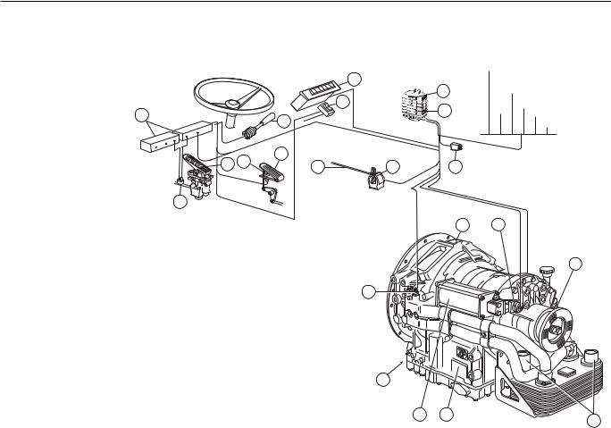
УКАЗАНИЕ
Изображение системы представляет одно из возможных устройств системы Ecomat 2/Ecomat 2 plus с EST46 C/EST47 C или с EST 146/EST 147 со всеми необходимыми отдельными
компонентами.
3
|
R |
|||||
|
DN |
4 |
||||
|
1 |
23 |
||||
|
24 |
5 |
||||
|
1 |
16 |
||||
|
15 |
17 |
18 |
|||
|
19 |
20 |
6 |
|||
|
25 |
4
|
Разъяснение к чертежу |
|||
|
1 |
Электрическая бортовая сеть |
15 |
Тормозной клапан с педальным |
|
3 |
Контроллер (цифровой контроллер, |
управлением для управления |
|
|
по выбору контроллер CAN) |
механизмом рабочей тормозной |
||
|
4 |
Фирменная табличка |
системы и плавного управления |
|
|
5 |
Электронное устройство |
тормозом-замедлителем с помощью |
|
|
автоматического переключения |
CAN |
||
|
передач EST46C/EST47C или |
16 |
Рычаг тормоза-замедлителя, |
|
|
EST146/EST147 |
электрический |
||
|
6 |
Вилка для подключения |
17 |
Переключатель kick-down |
|
MOBiDIG 200/TestmanPro |
18 |
Педаль акселератора |
|
|
8 |
Подключения охлаждающей жидкости |
19 |
Рычажный механизм для топливного |
|
9 |
Магнитный клапан для накопителя |
насоса высокого давления |
|
|
тормоза-замедлителя |
20 |
Датчик нагрузки (ZF-Ecomat 2- |
|
|
10 |
Пропорциональный магнитный клапан |
применение без CAN) |
|
|
для управления тормозом- |
24 |
Выключатель тормоза-замедлителя |
|
|
замедлителем |
ÂÊË-ÂÛÊË |
||
|
11 |
Датчик температуры |
25 |
Кнопочный выключатель для NBS |
|
12 |
Накопитель тормоза-замедлителя |
26 |
Импульсный датчик спидометра |
|
4139 758 903_21 — 2004-09 |
10 |
|
акселератора |
индикации |
|||
|
Тормоз |
Двигатель |
InstrumenteAnzeige- |
||
|
Gaspedal |
||||
|
Педаль |
Motor |
Приборы ……… ……. |
||
|
Bremse |
||||
Øèíà CAN
CAN-Bus
9
26
021649 8
- Home
-
Documents
- Ошибоки в системе АКПП ZF ЭКОМАТ 2 выдаваемые…
ZF список кодов ошибок Ecomat2 элемент ECUклемма 12 напряжение датчика нагрузки 24, 37, 38 12 — 13 выход напряжения (5V) 37 14 ручка управления ретардором 61 33 15 24, 37, 39 — 16 65, 12, 36 17 3 18 датчик темперетуры АКПП 27 21 электромагнитный клапан A 10 22 электромагнитный клапан B 4 23 электромагнитный клапан C 5 24 электромагнитный клапан D 9 25 электромагнитный клапан E 54 26 электромагнитный клапан F 29 27 электромагнитный клапан G 30 28 11 29 8 31 реле горного тормоза 52 32 55 33 — 34 реле V-сигнала 32 код неисправности ошибка настройки датчика нагрузки сигнал торможения ручное управление «ручное» (ручка управления ретардором) педаль управления ретардором ошибка настройки педали ретардера педаль управления ретардором датчик температуры ретардора электромагнитный клапан сцепления гидротрансформатора электромагнитный клапан гидроакумулятора опция. Реле сигналов торможения / реле сигнала передачи выход к реле сигнала передачи 2
-
Author
-
View
344 -
Download
17
Embed Size (px)
Text of Ошибоки в системе АКПП ZF ЭКОМАТ 2 выдаваемые…

ZF список кодов ошибок Ecomat2 EST146 уровень 2
элемент ECUклемма
12 напряжение датчика нагрузки 24, 37, 38
12 —
13 выход напряжения (5V) 37
14
ручка управления ретардором 61
33
15педаль управления ретардором 24, 37, 39
—
16 педаль управления ретардором 65, 12, 36
17 датчик температуры ретардора 3
18 датчик темперетуры АКПП 27
21 электромагнитный клапан A 10
22 электромагнитный клапан B 4
23 электромагнитный клапан C 5
24 электромагнитный клапан D 9
25 электромагнитный клапан E 54
26 электромагнитный клапан F 29
27 электромагнитный клапан G 30
28 11
29 8
31 реле горного тормоза 52
32 55
33 —
34 реле V-сигнала 32
коднеисправности
ошибка настройки датчика нагрузки
сигнал торможенияручное управление «ручное» (ручка управления ретардором)
ошибка настройки педали ретардера
электромагнитный клапан сцепления
гидротрансформатора
электромагнитный клапан гидроакумулятора
опция. Реле сигналов торможения / реле сигнала
передачи
выход к реле сигнала передачи 2

35 вход реле v-сигнала 2 —
36 31
37 выход к клапану Antigas 53
38 реле снижения нагрузки (опция) 32
39 56
41 лампа состояния 56
42 56
43 51
44 57
45 6
46контроллер переключения 21, 42, 28, 50, 41
ошибкаCAN, контроллера —
47 спидометр 59
48 14
49 результаты проверки EEPROM —
51 —
57
вход, вход скорость 40
40
57 замер входной скорости 40
58 вход , выход скорость 16
59 вход, ввод скорости из АКПП 62
61 статистические данные
64 —
68 —
76 —
77 —
выход к пропорциональному клапану
выход к реле электромагнитного привода блокировки
ADVP выход (постоянный сигнал)
входной сигнал для реле сигнализации торможения
ретардором
D1пропорциональный электромагнитный клапан
пропорциональный клапан ретардера
интерфейс широтно-импульсного модулятора
CAN 2, CANB(кумулятивная ошибка)
ввод скорости (B13):-отсоединение
-замыкание на массу- короткое замыкание с
источником High (+)
контроль проскальзывания АКПП
перезагрузка блокаEST146/147
проскальзывание элементов при переключении …
сигнализация»превышена нагрузка двигателя»

79 23, 68
81 —
82 данные —
83 реле заднего хода —
84 —
87
91 —
93 —
94 —
95 время переключения —
96 —
98—
Низший приоритет 0, высший приоритет 2
рабочее напряжение(терминал 30)
выходное реле контроллера переключений «нейтраль 1»
EEPROM данные заказчика(суммарные)
EEPROM корректирующие параметры
выходной сигнал для реализации спец. Функции 1
D1 уравнивание давление, задействовано переключение
вверх
уравнивание давления включения
D1уравнивание давления, переключение вниз
выходной сигнал для реализации спец. Функции 2
тестирование электронных компонентов

ZF список кодов ошибок Ecomat2 EST146 уровень 2
ZF приоритет описание
1
0
1 1
1 1
0
1
0
0 код не действителен
0 0
0 0
1 2 1
1 2 1
1 2 1
1 2 1
1 2 1
1 2 1
1 2 1
1 1 1
0 0 0
0 0 0
0 0 0
0 0 0
0 0 0
напряжение выше 4.8 Volt илиниже 0.2 Volt
превышен допустимый макс. Уровень
напряжение выше 5.2 Volt илиниже 4.5 Volt
напряжение выше4.8 Volt или ниже 0.2 Volt
несоответствие сигнала реальному параметру
напряжение выше 4.8 Volt или ниже 0.2 Volt
превышен допустимый макс. Уровень
напряжениевыше 4.8 Volt или ниже 0.5 Volt
напряжение выше 4.8 Volt или ниже 2.6 Volt
короткое замыкание на массу(плюс)разрыв цепи
короткое замыкание на массу(плюс)разрыв цепи
короткое замыкание на массу(плюс)разрыв цепи
короткое замыкание на массу(плюс)разрыв цепи
короткое замыкание на массу(плюс)разрыв цепи
короткое замыкание на массу(плюс)разрыв цепи
короткое замыкание на массу(плюс)разрыв цепи
короткое замыкание на массу(плюс)разрыв цепи
короткое замыкание на массу(плюс)разрыв цепи
короткое замыкание на массу(плюс)разрыв цепи
короткое замыкание на массу(плюс)разрыв цепи
короткое замыкание на массу(плюс)разрыв цепи
короткое замыкание на массу(плюс)разрыв цепи

0 0 0
0 0 0
0 0 0
0 0 0
0 0 0
0 0
0 0 0
0 0 0
1 1 1 1
1 1 1 1
0 ошибка кодировки
0
0 0
1
0
0
0
1
0
0
0
2
0
0 порог превышен
0
короткое замыкание на массу(плюс)разрыв цепи
короткое замыкание на массу(плюс)разрыв цепи
короткое замыкание на массу(плюс)разрыв цепи
короткое замыкание на массу(плюс)разрыв цепи
короткое замыкание на массу(плюс)разрыв цепи
короткое замыкание на массу(плюс)разрыв цепи
короткое замыкание на массу(плюс)разрыв цепи
короткое замыкание на массу(плюс)разрыв цепи
короткое замыкание на массу(плюс)разрыв цепи,
отклонение сопротивления
короткое замыкание на массу(плюс)разрыв цепи,
отклонение сопротивления
несоответствие сигнала реальному параметру
короткое замыкание на массу (плюс)
несоответствие сигнала реальному параметру
несоответствие сигнала реальному параметру
несоответствие сигнала реальному параметру
превышено максимальное значение
несоответствие сигнала реальному параметру
превышено максимальное значение
превышено максимальное значение
превышено максимальное значение
превышено максимальное значение
несоответствие сигнала реальному параметру
максимальное значение превышено

0 0 0
0 0 0
0 0 0
0
0 0 0
1
1
1
1
0 0
1
0 — 1 U_KL30 меньше 17,7 VoltU_KL30 больше 32,3 Volt
короткое замыкание на массу(плюс)разрыв цепи,
отклонение сопротивления
короткое замыкание на массу(плюс)разрыв цепи,
отклонение сопротивления
короткое замыкание на массу(плюс)разрыв цепи,
отклонение сопротивления
несоответствие сигнала реальному параметру
короткое замыкание на массу (плюс) разрыв цепи
несоответствие сигнала реальному параметру
отклонение параметра выше нормы
отклонение параметра выше нормы
отклонение параметра выше нормы
короткое замыкание на массу (плюс) разрыв цепи
несоответствие сигнала реальному параметру
Страница 48 из 63
Ecomat 2
Ecomat 2 auf RU

HP 502 C.
HP 592 C.
HP 602 C.
Как делать то.
Как делать ремонт zf ecomat.
ремонт HP 502 C.
ремонт HP 592 C.
ремонт HP 602 C.
оглавление скачать раздела ремонт
HP 502 C / HP 592 C / HP 602 C оглавление скачать
ZF список кодов ошибок Ecomat2
Кодировка световых сигналов
ZF Ecomat 2: Ремонт и эксплуатация
2004 год
язык русский
Автор: Фирма ZF Германия
Коробки передач для грузовиков и автобусов
Издательство: ZF Friedrichshafen
PDF
160 стр.
информация для обслуживания и ремонтных работ акпп ZF, ставят на грузовиках, спецтехнике и автобусах.
стоят на авто SCANIA, MAN, DAF и другие
На следующей странице, присутствуют еще книги по коробке передач серии ZF, типа 4 hp 20. Правда в той книге по 4 hp 20 язык английский, но страниц 825, пользуйтесь поиском по сайту.
4 hp 20
Теперь скачать бесплатно
еще
Книгу zf ecomat можно заказать в электронном виде ( стоимость 150 рублей,), написав на адрес
Адрес электронной почты защищен от спам-ботов. Для просмотра адреса в вашем браузере должен быть включен Javascript.
или на странице
обратная связь

Operating
Instructions
ZF-Ecomat
HP 500
HP 590
HP 600
ZF-Ecomat 2 / ZF-Ecomat 2 plus
HP 502
HP 592
HP 602
HP 502C HP 592C HP 602C
for city and intercity buses and
coaches
4139 758 103
Subject to alterations in design
Copyright by ZF
This documentation is protected by copyright. Any reproduction or dissemination in whatever form which does not
comply fully with the intended purpose of this documentation is prohibited without the consent of ZF Friedrichshafen AG.
Printed in Germany
ZF Friedrichshafen AG, MC-C / 2004-09
Edition: 2006-02
Preface
NOTE
All details in these Operating Instructions refer to the
basic version of the ZF-Ecomat transmission. Due to the
large number of installation options, no precise information can be provided for any specific vehicle. If there are
any differences in operation between the instructions in
this brochure and the Operating Instructions specific to an
individual vehicle manufacturer, the vehicle-specific
instructions are the ones to follow.
Before the vehicle first enters service, please note the
following points:
• Read the Operating Instructions carefully and follow the
safety instructions.
• To ensure that the transmission achieves the required
level of operational safety and reliability, always pay
careful attention to the maintenance instructions.
The ZF After-Sales Service specialists are available to
assist you in carrying out maintenance work at the transmission or to help if any other problems arise. Their
addresses are listed in the "ZF Company Directory" (order
number 0000 762 703) or on the Internet under
www.zf.com/ servicenetz.
4139 758 103 - 2004-09
Motoring pleasure with the ZF-Ecomat is brought to you
by
ZF Friedrichshafen AG
Commercial Vehicle and Special Driveline Technology
D-88038 Friedrichshafen
Tel.: +49 (0)7541 77-0
Fax: +49 (0)7541 77-90 80 00
Internet: www.zf.com
3
Safety Instructions
The following safety instructions appear in this manual:
!
NOTE
Refers to special processes, methods, information, etc.
CAUTION
This is used when incorrect, unprofessional working
practices could damage the product.
!
DANGER !
This is used when lack of care could lead to
personal injury or material damage.
THREATS TO THE ENVIRONMENT !
Lubricants and cleaning agents must not be allowed to
enter the soil, ground water, or sewage system.
• Ask your local environment agency for safety
information on the relevant products and adhere
to their requirements.
• Collect used oil in a suitably large container.
• Dispose of used oil, dirty filters, lubricants, and
cleaning agents in accordance with environmental
protection guidelines.
• When working with lubricants and cleaning agents
always refer to the manufacturer's instructions.
NOTE on cleaning the vehicle / transmission
CAUTION
When cleaning, always ensure that the steam cleaner or
high-pressure cleaner does not make direct contact with
the screw cap of the dipstick. Any water ingress through
the breather can damage the transmission!
4139 758 103 - 2004-09
4
Contents
1
Description . . . . . . . . . . . . . . . . . . . . . . . . . . . 6
1.1
1.2
1.3
1.4
Structure of Basic ZF-Ecomat Transmission . . . . . . . 7
System Solution for ZF-Ecomat . . . . . . . . . . . . . . . . 9
System Solution for ZF-Ecomat 2/
ZF-Ecomat 2 plus . . . . . . . . . . . . . . . . . . . . . . . . . . 11
Auxiliary Transmission . . . . . . . . . . . . . . . . . . . . . . . 12
2
Operation . . . . . . . . . . . . . . . . . . . . . . . . . . . 13
2.1
2.1.1
2.1.2
2.2
2.3
2.4
2.5
2.5.1
2.5.2
2.5.4
2.6
2.7
2.7.1
2.7.2
Speed Range Selector . . . . . . . . . . . . . . . . . . . . . . 13
Digital Speed Range Selector . . . . . . . . . . . . . . . . . 13
CAN Speed Range Selector . . . . . . . . . . . . . . . . . . 14
Starting Engine . . . . . . . . . . . . . . . . . . . . . . . . . . . . 15
Engaging Gear . . . . . . . . . . . . . . . . . . . . . . . . . . . . 15
Setting Off . . . . . . . . . . . . . . . . . . . . . . . . . . . . . . . 16
Speed Ranges . . . . . . . . . . . . . . . . . . . . . . . . . . . . 17
Driving Downhill . . . . . . . . . . . . . . . . . . . . . . . . . . . 17
Change in Direction of Travel . . . . . . . . . . . . . . . . . . 17
Retarder Operation . . . . . . . . . . . . . . . . . . . . . . . . . 19
Stopping, Parking . . . . . . . . . . . . . . . . . . . . . . . . . . 21
Towing . . . . . . . . . . . . . . . . . . . . . . . . . . . . . . . . . . 22
Towing a Vehicle with Operational Transm. . . . . . . . 22
Towing a Vehicle with Suspected Transmission
Damage . . . . . . . . . . . . . . . . . . . . . . . . . . . . . . . . . 22
Temperature Monitoring . . . . . . . . . . . . . . . . . . . . . 23
Limit Values for Oil Temperature . . . . . . . . . . . . . . . 23
2.8
2.9
4139 758 103 - 2004-09
2.9.1 Transmission Oil Temperature Upstream of Oil Cooler 23
2.9.2 Oil Temperature in Transmission Sump . . . . . . . . . . 23
2.9.3 Action When Permitted Oil Temperature Limit is
exceeded . . . . . . . . . . . . . . . . . . . . . . . . . . . . . . . . 24
2.10 Status Monitoring / Warning Lamps . . . . . . . . . . . . 24
2.11 Transmission Response to a Malfunction . . . . . . . . . 25
2.11.1 Limp-Home Mode . . . . . . . . . . . . . . . . . . . . . . . . . . 25
2.12 Auxiliary Control Unit . . . . . . . . . . . . . . . . . . . . . . . 26
2.12.1 Operating Instructions for the Auxiliary Control Unit 26
3
Maintenance . . . . . . . . . . . . . . . . . . . . . . . . . 28
3.1
3.2
3.3
3.3.1
3.3.2
3.3.3
Oil Grade . . . . . . . . . . . . . . . . . . . . . . . . . . . . . . . . 28
Oil Quantities in the ZF-Ecomat . . . . . . . . . . . . . . . 29
Oil Level Check . . . . . . . . . . . . . . . . . . . . . . . . . . . . 29
Checking at Operating Temperature . . . . . . . . . . . . 30
Reference Value Calculation . . . . . . . . . . . . . . . . . . 30
Checking With Separate Heat Exchanger
Mounted Above Centerline of Transmission . . . . . . . 32
Option for Heating Up the Transmission Oil . . . . . . . 32
Oil Change Intervals . . . . . . . . . . . . . . . . . . . . . . . . 33
Draining the Oil . . . . . . . . . . . . . . . . . . . . . . . . . . . . 34
Filling With Oil . . . . . . . . . . . . . . . . . . . . . . . . . . . . 34
Draining / Filling Oil on ZF Angle Drive . . . . . . . . . . 35
Checking the Load Sensor Setting (Ecomat) . . . . . . 36
Trouble shooting . . . . . . . . . . . . . . . . . . . . . . . . . . .37
3.4
3.5
3.6
3.7
3.8
3.9
5
Description
1
Description
The hydrodynamic retarder is installed between the torque converter and the planetary transmission. This means
that the level of retarder braking force on the output shaft
is gear-dependent. As a consequence, full braking action is
available, even at the lower end of the speed range. The
braking torque can be controlled across an infinitely
variable range or can be sub-divided into several steps.
The Ecomat range of transmissions comprises a hydrodynamic torque converter (Föttinger t/c) with lock-up clutch,
a hydrodynamic retarder, and a downstream, multi-ratio
planetary transmission.
The torque converter is a starting unit which operates
without mechanical wear and which adapts its setting
across an infinitely variable range to suit prevailing conditions (delivering the required level of input torque).
Braking action while driving downhill or in city traffic can
be delivered by the retarder without mechanical wear,
thereby extending the life of the service brakes.
ZF offers a range of powerful PTOs for the entire range of
Ecomat applications. These PTOs are engine-dependent
and, depending on their version are either permanently
driven or disengagable.
The gears in the planetary transmission are engaged
automatically without any interruption in traction. The
signals for gear changes are supplied by an ECU (electronic shift control unit). Depending on various parameters
obtained from vehicle and transmission, this ECU engages
the appropriate multi-disc clutches and brakes via the
electro-hydraulic transmission control unit.
A lock-up clutch installed in the torque converter establishes a direct mechanical connection between engine and
planetary transmission after the starting phase. This lockup process eliminates the power losses traditionally associated with torque converter transmission.
4139 758 103 - 2004-09
6
Description
1.1 Structure of Basic ZF-Ecomat Transmission
1
2
3
4
5
6
7
8
011 561
4139 758 103 - 2004-09
7
Key to drawing
1 Input
2 Torque converter lock-up clutch
3 Torque converter
4 Hydrodynamic retarder
5 Rotating multi-disc clutches
6 Fixed-position multi-disc brakes
7 Output
8 Oil cooler
Description
NOTE
This system diagram illustrates one of the possible system solutions for the ZF-Ecomat with the ECU 18 electronic
shift control unit and all related components.
3
2
1
Key to drawing
1 Vehicle circuit interface
2 Temperature display unit
3 Speed range selector (digital speed
range selector)
BN 1
4 Type plate
BN 2
16
17
5 ECU 18 electronic shift control unit
6 Plug connection for
17 19
18
19
7
18
20
MOBiDIG 2000 / ZF-TestmanPro
7 From air supply for auxiliary
consumers
24
8 Coolant connections
9 Solenoid valve for retarder accumulator
10 Retarder accumulator
21
11 Solenoid valve for retarder activation
22
12 Temperature sensor
13 Pressure relief valve (1.2 bar)
14 Solenoid valve for retarder torque
15
16
7
reduction
15 Pressure switch (retarder input signal
15
for ECU 18)
16 Footplate brake valve with modulator valve for
activating the service brake
17 Retarder hand lever
18 Kickdown switch
19 Accelerator pedal
20 Linkage for fuel injection pump
21 Load sensor for recording engine load status
22 Compressed air line for retarder activation (optional
23 Changeover valve
15 and/or 16). Pressure line for modulated pressure
24 Brake pedal for service brake
(0 to 3 bar)
activation
4
5
6
20
21
44
23
14
10
08
13 12 11
00
10
44
97
9
88
023807
023807
4139 758 103 - 2004-09
8
Description
1.2 System Solution for the ZF-Ecomat
• The speed range selector (3) can be used to pre-select the
speed range.
The pushbutton activated then lights up (continuous
light).
HP 500, HP 590, HP 600 range with ECU 18
for city & intercity buses and coaches.
The electrical wiring from the Ecomat system to the ECU
shift control unit is routed via the vehicle circuit interface
(1).
• Using the kickdown switch (18), the shift points can be
relocated to a higher speed range which means that the
transmission remains in each gear for more extended
periods or that downshifts occur sooner.
The ECU18 (5) electronic automatic shift system is used to
control and monitor transmission operation. The ECU
records input parameters from vehicle and transmission
(speed range, engine load, speeds etc.) and converts them
into signals to activate the hydraulic transmission unit.
• To activate the retarder, refer to vehicle Operating
Instructions.
• Temperature sensors are installed to monitor the oil temperature. The temperature is displayed by means of an
analog display (2) or warning lamp.
Whenever defined temperature limits are exceeded,
retarder torque is reduced continuously.
The driver can intervene directly in the Ecomat control
unit using the
• speed range selector (pushbutton switch) (3)
• kickdown (18)
• accelerator pedal (19)
• brake pedal (24)
• retarder activation switch (16)
4139 758 103 - 2004-09
• Engine load information is transmitted from the electronic engine control unit to the ECU18 (5).
9
Bremse
Gaspedal
Motor
Anzeige-Instrumente
.........
.......
Description
NOTE
The system diagram illustrates one of the possible system solutions for the Ecomat 2 /
Ecomat 2 plus with ECU 46 C/ECU 47 C and/or ECU 146/ECU 147 respectively with
all required components.
3
NR
3D
1 2
4
24
1
5
16
CAN-Bus
15 17
18
19
6
20
25
4
Key to drawing
1 Vehicle circuit
3 Speed range selector (digital speed range
selector with option of CAN speed range
selector)
4 Type plate
5 ECU (electronic shift control unit)
ECU46C/ECU47C and/or ECU146/ECU147
6 Plug connection MoBiDIG 200/
TestmanPro
8 Coolant connections
9 Solenoid valve for retarder accumulator
10 Proportional solenoid valve for retarder
activation
11 Temperature sensor
12 Retarder accumulator
4139 758 103 - 2004-09
9
26
15 Footplate brake valve for activation of
service brake and infinitely variable
retarder activation via CAN
16 Retarder hand lever, electrical
17 Kick-down switch
18 Accelerator pedal
19 Linkage to fuel injection pump
20 Load sensor (ZF-Ecomat-2 application
without CAN)
24 Retarder switch ON/OFF
25 Pressure switch for NBS (Bus Stop
Neutral)
26 Impulse sensor, speedometer
10
11
10
12
4
021649
8
Description
1.3 System Solution for ZF-Ecomat 2/ZF-Ecomat 2
plus
• Using the kickdown switch (17) the shift points can be
relocated to a higher speed range, i.e. the transmission
then spends longer in each ratio before upshifts and that
downshifts occur sooner.
HP 502, HP 592, HP 602 range and/or ECU 502 C and
HP 592 C, HP 602 C with ECU46C / ECU47C and
ECU 146 / ECU 147 respectively, for city & intercity
buses and coaches (C=CAN-capable)
• Activation of the retarder: Refer to vehicle Operating
Instructions.
The electrical wiring from the Ecomat system is routed to
the ECU and to the CAN bus in the vehicle via the vehicle
circuit interface (1).
• Temperature sensors are installed to monitor the oil temperature. This information is transmitted via CAN bus,
digital output on the ECU or via direct wiring and is displayed by means of a display panel, analog display or
warning lamp. Whenever defined temperature limits are
exceeded, retarder torque is reduced continuously.
The (electronic automatic shift system) ECU helps to control and monitor operation of the transmission. The ECU
records input parameters from vehicle and transmission
(speed range, engine load, speeds etc.) and processes these
into signals to activate the hydraulic transmission control
unit.
• Engine load information is transmitted from the electronic engine control unit to the ECU by means of CAN or
load sensor (20) or PWM signal.
In conjunction with a proportional solenoid in the electro-hydraulic control unit, pressures for activating the
clutch elements are modulated in accordance with engine load.
The driver can intervene directly in the Ecomat control
unit using the
• speed range selector (pushbutton switch) (3)
• kickdown (pushbutton switch) (18)
• accelerator pedal (19)
• brake pedal (24)
• retarder activation switch (16)
• Special feature of the Ecomat 2 plus:
This range of transmissions has been designed to contend with higher temperatures by means of a choice of
modified sub-assemblies built with adapted materials,
refer to Chapter 2.9.
• The speed range selector (3) can be used to pre-select the
speed range. The pushbutton activated then lights up
(continuous light).
4139 758 103 - 2004-09
11
Description
1.4 Auxiliary Transmission
Depending on vehicle version and application, the ZF-Ecomat transmission can be equipped with an 80° angle drive or with an ST
10000 angle drive.
!
"
Key to drawing:
1 Basic transmission
2 Coaxial output
3 80° angle drive without LHD axial offset or 80° angle drive with RHD axial offset RHD
4 ST 10000 angle drive
4139 758 103 - 2004-09
12
019994
Operation
2
Operation
2.1.1 Digital Speed Range Selector
2.1
Digital and/or CAN speed Range Selector
3, 5, or 6 pushbuttons installed horizontally or vertically
R
= Reverse
N
= Neutral
D
= Automatic forward driving range (Drive)
1, 2, 3 = limited forwards driving ranges
Example
NOTE
• The respective button pushed will then lights up (continuous light).
• The respective button pushed flashes if it is not accepted by the transmission control unit.
005624
The vehicle is either equipped with a digital or a CAN
speed range selector switch.
NOTE
Distinguishing features between CAN and digital speed
range selector switches:
• Convex keys
• Neutral button does not lock
• ZF-Logo located laterally on Neutral button
4139 758 103 - 2004-09
13
Operation
2.1.2 CAN Speed Range Selector
Exceptions:
• If the transmission control unit is not providing the
information required for lighting purposes, the lamps
only light up in search mode. Nevertheless, the vehicle
can still be driven in this status.
2.1.2.1 Lighting of the CAN Speed Range Selector
Button lighting colors:
• Neutral button:
• 1,2,3, D and R:
Amber
Yellow
All buttons light up for approx. 1.2 s:
• Lighting test at system startup
• The lighting is also deactivated if the pushbutton position can no longer be correctly established as a result of
a hardware defect and the buttons only light up with
search lighting.
All buttons flash:
• Serious internal fault in pushbutton
• Malfunction in CAN communication. Once this defect
has been remedied, the lamp stops flashing.
NOTE
The lighting levels for search and function lighting can, if
required, be set independently of one another. These
levels are corrected in accordance with battery voltage.
All lamps light up dimly:
• Search lighting: To make it easier to find the buttons in
the dark.
2.1.2.2 Pushbutton Settings
NOTE
If several buttons are selected at the same time, the smallest gear inhibit button selected is chosen.
Individual buttons light up brightly:
• Function lighting: Identifies the active, pressed
pushbutton.
4139 758 103 - 2004-09
E.g.: If buttons 1, 2, 3 and D are selected at the same time,
button 1 is activated.
14
Operation
2.2
Starting Engine
Transmission with additional "gear release" function
(additional installation by vehicle manufacturer, recommended by ZF)
• Speed range selector in Neutral position
• Accelerator pedal at idle setting and neng < 900 rpm
• Select desired speed range and apply brake. System will
only select the desired gear while the brake is being
applied.
Engine can only be started if:
• Vehicle is stationary (brake applied)
• Speed range selector is in Neutral position ("N")
NOTE
Starter inhibit: If the speed range selector is not in Neutral position, the engine cannot be started.
Operator errors when engaging gear
• Accelerator pedal actuated or neng > 900 rpm
• If "gear release" is installed, but brake not applied
• Direction of travel "R" selected at a vehicle speed of
> approx. 3 km/h
After selecting the desired speed range, the system does
not engage a gear.
CAUTION
Jump-starting only possible on battery, never on starting
motor!
Do not switch ignition OFF / ON while vehicle is in
motion!
2.3
Transmission with auxiliary function "2nd Reverse gear
button"
• To reverse the vehicle, press the R button on the speed
range selector and also the R button on the dashboard.
Engaging Gear
Standard:
• Speed range selector in Neutral position
• Accelerator pedal at idle setting and neng < 900 rpm
• Select desired speed range and/or direction of travel.
CAUTION
Never actuate speed range selector and throttle at the
same time!
4139 758 103 - 2004-09
15
Operation
2.4 Setting Off
After selecting the appropriate speed range, wait for
approx. 1 to 2 seconds, release brake (if applied) and
accelerate.
!
DANGER !
On steep uphill gradients, always accelerate as soon
as you release the brake! RISK OF ACCIDENT from
vehicle rolling backwards!
CAUTION
Do not set off immediately at temperatures below -15 °C.
Instead, allow engine to warm up for approx. 5 minutes.
Speed range selector in Neutral position.
4139 758 103 - 2004-09
16
Operation
2.5
Speed Ranges
2.5.1 Driving Downhill
Please refer to the vehicle's Operating Instructions for
precise information about the gears engaged in each of the
speed ranges.
When driving down steep gradients, depending on requirements, you should select setting 1, 2, or 3 on the speed
range selector. This restricts upshifts.
A defined range of gears / ratios is assigned to each speed
range. Shifts are only executed at shift points defined by
the electronic shift control unit.
!
Manual intervention in the automatic shift sequence
(shifting right through the speed ranges) is not advisable.
!
DANGER !
If the transmission is shifted into "N" while the vehicle
is in motion, the power flow between engine and output is interrupted. This prevents the engine brake and
retarder from being able to operate.
Risk of accident! - Apply brake!
For safety reasons, when faults occur in the electronic
shift control unit or whenever there is a power failure,
the transmission automatically selects "N".
4139 758 103 - 2004-09
DANGER !
In extreme cases, to protect the engine, the upshift
inhibit is disabled.
In such cases, the transmission is able to change up
into top gear, regardless of which speed range is
selected.
RISK OF ACCIDENT!
Keep a close eye on the tachometer!
2.5.2 Change in Direction of Travel
Before changing from Forward to Reverse or vice versa:
• Vehicle stationary
• Accelerator pedal at idle setting and neng < 900 rpm
• Speed range selector in Neutral position, actuate brake
pedal if necessary
• Move speed range selector to D, 1, 2, 3, or R
17
Operation
2.5.3 Kick-Down
To utilize max. engine power, higher shift points can be
called up using the kick-down switch (see illustration) or
the CAN system (to accelerate or to use the accelerator
pedal on uphill gradients).
Accelerator pedal
Full load (pressure
point)
• Depress accelerator pedal right through full throttle
pressure point (kick-down position).
Kick-down
Kick-down switch
023629
4139 758 103 - 2004-09
18
Operation
Ac
ce
ler
ato
rp
ed
al
2.5.4 Retarder Operation
The retarder is a ratio-dependent hydrodynamic brake
which operates without mechanical wear. The retarder
should be employed every time the brakes are applied.
This extends the life of the service brake. The retarder can
be activated manually and/or using the foot controls.
ch
rei
Be
r
de
tar
Re
rder
Reta
+
h
ereic
ms-B
e
r
b
iebs
Betr
Conditions for retarder operation
(retarder engaged / actuated)
• Accelerator pedal in idle speed setting
• A forward gear must be engaged
013186
• Vehicle speed > approx. 3 km/h
If these conditions are met, the system prevents upshifts
(upshift inhibit).
6
5
CAUTION
If the accelerator pedal is actuated, the retarder
disengages.
The upshift inhibit is cancelled.
4
3
2
1
0
023630
4139 758 103 - 2004-09
19
Operation
The retarder must be switched off:
• On icy roads
• Whenever the oil temperature rises above 150 °C
The max. permitted oil temperature during retarder
operation is 150 °C.
Temperature display or temperature warning:
Refer to chapter 2.8 or vehicle manufacturer's Operating
Instructions!
• Retarder activation using foot pedal, de-activation using
toggle switch on dashboard
• Switch off hand lever whenever the brake has been
applied!
!
DANGER !
The retarder is automatically governed back by means
of a specified transmission oil temperature characteristics curve.
Risk of accident as a result of reduced braking
capability!
4139 758 103 - 2004-09
20
Operation
2.6 Stopping, Parking
Transmission with special "Bus Stop Neutral" (NBS)
feature
NOTE
Only use parking brake when vehicle is stationary.
The transmission automatically selects Neutral when the
following conditions are in place simultaneously:
• Vehicle stationary
Stopping
• Brake applied
The vehicle can be stopped at any time, regardless of the
setting of the speed range selector. The electronic shift
control unit then engages the appropriate gear for setting
off.
• Accelerator pedal in idle speed setting
The speed range selector remains in its most recently
selected setting.
As soon as any one of the above three conditions ceases to
apply, the transmission automatically engages 1st gear.
With short stops:
• Speed range can remain selected
• Apply brake
Parking
At extended stops:
• Speed range selector in Neutral position
• Speed range selector in Neutral position
• Apply parking brake
• Apply brake
!
4139 758 103 - 2004-09
21
DANGER !
Before leaving the vehicle, always apply the parking
brake. When the engine is switched off, there is no direct
connection between engine and axle. The vehicle can
therefore start to roll!
Operation
2.7
Towing
2.7.2 Towing a Vehicle With Suspected Transmission
Damage
2.7.1 Towing a Vehicle with Operational Transmission
CAUTION
If transmission damage is suspected, flange on universal
shaft between transmission and drive axle needs to be
disconnected.
• Speed range selector in Neutral position
• Max. towing time: 2 hours
• Max. towing speed:
City and intercity buses:
Coaches:
Exception: In a dangerous situation, towing is permitted
until vehicle leaves the area of immediate danger (e.g.
crossroads, tunnel etc.) even without disconnecting the
driveline.
25 km/h
35 km/h
NOTE
At an ambient temperature of less than -15 °C the towing
speed is 5 km/h.
4139 758 103 - 2004-09
22
Operation
2.8
Temperature Monitoring
2.9.2 Oil Temperature in Transmission Sump
The transmission temperature monitoring function is performed by the electronic automatic shift system (Ecomat 2
and Ecomat 2 plus) and/or via a temperature indicator
(Ecomat).
The actuation point of temperature indicator warning
contact is 145 °C.
2.9
NOTE
The following sump temperatures must not be exceeded
(not even at high ambient temperatures):
Transmission oil sump temperatures
Limit Values for Oil Temperature
Operating
temperature
or continuous
temperature
2.9.1 Transmission Oil Temperature Upstream of
Oil Cooler
During retarder operation:
• In exceptional cases, short periods of operation
(max. 5 mins. within a 1 hour period) at 150 °C are
permissible.
Exception:
Max. 5 Min.
within any
1 hour period
During torque converter operation:
• The temperature limit for continuous operation is
110 °C.
• In exceptional cases, short periods of operation
(max. 5 mins. within a 1 hour period) at 130 °C are
permissible.
During normal driving:
• The permitted temperature range is between 90 - 100 °C.
4139 758 103 - 2004-09
23
Ecomat
Ecomat 2
Ecomat 2 plus
max.
80 - 90 °C
max.
100 °C
max.
105 °C
105 °C
105 °C
115 °C
Operation
2.9.3 Action When Permitted Oil Temperature Limit is
Exceeded
2.10 Status Monitoring / Warning Lamps
The diagnosis system on the electronic automatic shift
system (the ECU) monitors the transmission status every
time the vehicle circuit is switched on and continuously
while the vehicle is in motion.
• Driving at part throttle in low driving range
• Switch off retarder
If this does NOT cause the oil temperature to drop:
Warning lamps
Faults are displayed by warning lamps lighting up (red or
yellow) and by warning messages which appear on the
driver's display panel (refer to the vehicle manufacturer's
Operating Instructions).
• Stop the vehicle
• Speed range selector in Neutral position
• Run engine at raised idle speed
NOTE
If the temperature does not drop back into its permitted
range within a few minutes, the possible causes are:
If a selected gear or speed range is not accepted by the
ECU, the button pressed on the speed range selector starts
to flash.
• Oil level too low or too high
• Coolant circuit defective
• Transmission damage
Inform ZF Service Center without delay!
4139 758 103 - 2004-09
24
Operation
2.11 Transmission Response to a Malfunction
2.11.1 Limp-Home Mode
To protect the transmission in the event of a malfunction,
the following responses are provided:
The ECU is set up with specific time and pressure settings
for pressure control in limp-home mode. Please also note
that:
Shift into Neutral:
In the event of major malfunctions in the power supply to
the transmission, e.g. short circuit
• The retarder function is not available
• The "Bus Stop Neutral" (NBS) function is not available
• The engine brake cannot be activated
Shift into Limp-Home Mode:
If there is an interruption to CAN communication or a loss
of speed information
!
• "Torque converter lock-up clutch" (WK) is open
• Engine torque is limited to protect the transmission (no
engine management)
DANGER !
In the event of a malfunction occurring in the transmission system:
• There is an extremely high risk of transmission
damage
• Restricted system monitoring
RISK OF ACCIDENT!
4139 758 103 - 2004-09
25
Operation
2.12 Auxiliary Control Unit
2.12.1 Operating Instructions for the Auxiliary Control
Unit
This auxiliary control unit was developed to help with
moving the vehicle during the production process and to
act as a limp-home facility in the event of ECU failure.
• Apply parking brake to prevent vehicle from rolling
accidentally.
• Speed range selector in Neutral position ("N")
Auxiliary control unit HST 18 (Ecomat)
The HST 18 auxiliary control unit is fitted to the 55-pin
connector instead of the ECU18 unit (i.e. the normal
ECU). This allows the driver to select one forward and
one reverse gear. No gear changes are possible while the
vehicle is in motion.
• Switch off engine and ignition.
• Remove connector from ECU 46 C / ECU 47 C and/or
ECU 146 / ECU147 control unit.
• Attach connector to HST 18 auxiliary control unit and
secure.
Auxiliary control unit HST 46 (Ecomat 2/ Ecomat 2 plus)
The HST 46 auxiliary control unit is fitted to the 68-pin
connector instead of the ECU 46 C / ECU 47 C and/or
ECU 146 / ECU 147 units (i.e. the normal ECUs). This
allows the driver to select one forwards and one reverse
gear. No gear changes are possible while the vehicle is in
motion.
4139 758 103 - 2004-09
• Start engine.
• Engage gear on speed range selector:
26
• Shift setting "N"
= Neutral
• Shift setting "D"
= Forward (gear is engaged, and
no upshifts or downshifts
occur)
• Shift setting "R"
= Reverse
Operation
!
DANGER !
When the auxiliary control unit is in operation, none of
the safety functions are operational.
RISK OF ACCIDENT!
Please therefore pay careful attention to the following
points:
• Shifting from "N" to "D" or from "N" to "R" ; only ever
possible at idle speed and while vehicle is stationary. The transmission can also perform gear changes
at higher engine speeds - however this does lead to
transmission damage.
• Before every change from forwards to reverse travel
or vice versa, always ensure that the vehicle is completely stationary.
• After shifting into "D" or "R", always wait for 2
seconds to enable the transmission to engage before starting to accelerate.
4139 758 103 - 2004-09
27
Maintenance
3
Maintenance
3.1 Oil Grade
Good maintenance delivers operational reliability for the
transmission. It is therefore very important to ensure that
all maintenance work required is consistently carried out
to the required standard.
!
CAUTION
When filling Ecomat transmissions, always use oils specified on the latest version of the ZF List of Lubricants TEML 14:
• The most recent version of this List of Lubricants can
be obtained from all ZF Sales & Service Centers, or can
be downloaded from the Internet from www.zf.com
(Products for → Technical Information → List of Lubricants).
THREATS TO THE ENVIRONMENT!
Lubricants and cleaning agents must not be allowed to
escape into the ground, surface water or the drainage
system.
•Ask your local environment agency for safety information on the relevant products and adhere to their
requirements.
•Collect used oil in a suitably large container.
•Dispose of used oil, dirty filters, lubricants, and
cleaning agents in accordance with environmental
protection guidelines.
•When working with lubricants and cleaning agents
always refer to the manufacturer's instructions.
4139 758 103 - 2004-09
28
Maintenance
3.2 Oil Quantities in the ZF-Ecomat
3.3 Oil Level Check
For the initial fill of a dry transmission, approx. 28 liters
(dm3)
CAUTION
Achieving the correct oil level is extremely important.
After installation of new / replacement transmissions,
approx. 20 liters (dm3)
!
After oil changes: After approx. 10 minutes, the following
oil quantities are setting
Ecomat, flat oil pan:
approx. 12 dm3
Ecomat, deep oil pan:
approx. 13 dm3
Ecomat 2, flat oil pan:
approx. 17 dm3
Ecomat 2, deep oil pan:
approx. 18 dm3
NOTE
The vehicle must be parked on level ground when checking the oil level.
CAUTION
• Check the oil level at operating temperature to obtain a
definitive figure.
• Check the oil level at the quarterly service interval in
the workshop.
• Conduct regular visual inspections of the transmission
for signs of leakage.
• In exceptional cases the oil level may need to be checked while the transmission oil is cold - refer to Chapter 3.3.2. Then always check the oil again at normal
operating temperature.
• If the heat exchanger is arranged above the centerline
of the transmission (separate installation), the oil level
must be checked in accordance with Chapter 3.3.3.
NOTE
With the optional extra of auxiliary cooling, the oil quantity increases to approx. 2 dm3.
CAUTION
The figures shown here are intended for guidance. In all
cases, measurement with the dipstick provides the definitive value.
4139 758 103 - 2004-09
DANGER !
Insufficient oil in the system leads to partial or complete failure of the retarder, i.e. braking action is
impaired or non-existent.
29
Maintenance
3.3.1 Checking Oil at Operating Temperature
3.3.2 Reference Value Calculation
The definitive temperature reading is always the one
obtained from the hot transmission oil (80 to 90 °C).
This oil level measurement, carried out while the transmission oil is cold, is applied under the following exceptional circumstances:
Conditions:
• When a transmission enters service for the first time
• Park vehicle on level ground
• After extended stationary periods, e.g. when taking over
a third party vehicle
• Move speed range selector into Neutral
• Let engine run at idle speed
After waiting for approx. 2 minutes, the oil level should be
up in the hot range.
CAUTION
The engine idle speed should be set to between 500 and
700 rpm. It must never drop below 450 rpm.
• Following repair work on a vehicle transmission: E.g.
removal of the oil pan, hydraulic control unit, oil cooler
etc.
• After oil or filter changes
Calculation of the flat rate (labor charge) can be divided
into three steps:
• Checking before starting the engine
• Checking after starting the engine
Afterwards, inspection at operating temperature must be
performed.
Hot range 80 - 90 °C {
011577
4139 758 103 - 2006-02
30
Maintenance
3.3.2.1 Checking Before Starting the Engine
3.3.2.2 Checking After Starting the Engine
The oil level must be within or above the range called
"neng = 0".
Run the engine for approx. 3 to 5 minutes at idle speed
(speed range selector in Neutral), then check the oil level.
The oil level should be inside the defined 30 °C range.
NOTE
If the oil level is higher than this, do not drain any oil!
Stationary range (neng = 0)
NOTE
If the oil level is higher than this, do not drain any oil!
CAUTION
After cold starts at sub-zero temperatures, the tip of the
dipstick must be immersed at least 10 mm in the oil before considering the oil to have reached operating temperature (to obtain a valid reading). The definitive oil level
check (at operating temperature) should be conducted as
soon as possible, (refer to Chapter 3.3.1).
{
011577
Cold range 30 °C {
011577
4139 758 103 - 2004-09
31
Maintenance
3.3.3 Checking With Separate Heat Exchanger Mounted Above Centerline of Transmission
3.4
Option for Heating Up the Transmission Oil
The transmission oil can be heated up to its specified
operating temperature for oil check purposes by running
the vehicle, running retarder cycles until the oil sump
temperature reaches 80 - 90 °C.
Run transmission in Neutral for 15 to 20 seconds at neng =
1200 to 1500 rpm.
NOTE
Within 3 minutes of engine running at idle speed, perform
the "Check After Starting the Engine" (Chapter 3.3.2.2) closely followed by the "Check at Operating Temperature"
(Chapter 3.3.1).
If normal operation of the vehicle is not possible, the oil
needs to be heated up in one of the following ways:
• Apply parking brake
• Select speed range "D"
• Apply the service brake
• Run engine several times at part throttle (as required)
for 15 to 20 seconds at 1200 to 1500 rpm.
CAUTION
Max. permitted oil temperature upstream of heat
exchanger is 110 °C (continuous).
After every heating phase and with the transmission in
Neutral, run engine at 1500 to 2000 rpm for 15 to 30
seconds.
4139 758 103 - 2004-09
32
Maintenance
3.5
Once the oil has reached operating temperature:
• Transmission in Neutral
Oil Change Intervals
The oil change intervals defined in ZF List of Lubricants
TE-ML 14 are binding.
• Run engine for 2 to 3 minutes
Then check oil level as described in Chapter 3.3.1.
NOTE
The latest List of Lubricants can be obtained from all ZF
Sales & Service Centers or can be downloaded from the
Internet under www.zf.com (Information → Technical
Information → List of Lubricants.
CAUTION
The oil filter must be replaced at every oil change.
NOTE
When changing the oil from a mineral-based to a partially
synthetic, hydrocracked, or synthetic grade of ATF, it is
advisable to conduct an intermediate oil change at the half
way point to the next specified service interval.
4139 758 103 - 2004-09
33
Maintenance
3.6 Draining the Oil
3.7 Filling With Oil
NOTE
Drain the oil - only while at operating temperature and
over a period lasting at least 10 minutes.
• Fit filter cover (screw tightening torque 25 Nm)
• Screw in oil drain plug (1) (tightening torque
50 Nm)
• Engine must be stationary
• Remove dipstick (3)
• Unscrew oil drain plug (1) and drain oil
• Top up oil (for oil quantities, refer to Chapter 3.2)
• Remove filter cover (2)
• Check oil level in accordance with Chapter 3.3
• Replace filter cartridge, copper rings, and O-rings
3
013172
2
4139 758 103 - 2004-09
1
013173
34
Maintenance
3.8 Draining / Filling Oil on ZF Angle Drive
NOTE
The ZF angle drive shares an oil supply with the ZFEcomat.
Oil fill quantity: approx. 1 dm3
Oil grade:
In accordance with List of Lubricants TE-ML 14 (Chapter
3.1)
Oil change intervals:
In conjunction with the Ecomat transmission
NOTE
Drain the oil: Only when at operating temperature
ZF 80° angle drive
• Engine must be stationary
• Unscrew oil drain plug on angle drive and drain oil
• Screw oil drain plug into angle drive (tightening torque
50 Nm)
ZF ST 10000 angle drive
This angle drive does not have its own oil drain plug. Its
oil is drained from the main transmission circuit.
4139 758 103 - 2004-09
35
Maintenance
3.9 Checking the Load Sensor Setting (Ecomat)
CAUTION
• Do not use detents on load sensor housing for setting
purposes.
• Do not unfasten screws on load sensor housing or nut
on shaft.
• Check ball heads for wear (excessive clearance) and
grease fill.
The setting of the load sensor must be checked:
• After all maintenance on transmission or engine
• If hard shift impacts occur
• At least once every 3 months
Implementing checks
(for this check to be effective, the engine must be at the
correct setting)
Detents
This level check can be conducted using the marks on the
front face or top of the housing.
• Switch off engine
• Apply parking brake
low
• Slowly depress accelerator pedal to its pressure point
(full throttle detent on fuel injection pump), press firmly
- but do not go past the kickdown point.
000822
low
• Maintain accelerator pedal setting; mark on load sensor
lever must match the full throttle mark (high) on the
housing.
• Release accelerator pedal until idle speed setting is
reached.
high
000824
• Mark on load sensor lever must be aligned with idle
speed mark (low) on housing.
4139 758 103 - 2004-09
high
36
Trouble shooting
Error
Possible cause
Remedial action
Engine will not start
Speed range selector not in "Neutral"
Select "Neutral" on speed range selector
ECU connector loose
Re-establish plug connection
Starter inhibit relay defective or missing
CAN signal
Replace relay or check CAN signal
Accelerator pedal not in idle speed position
or load signal too high
Check or adjust settings of accelerator
pedal / fuel injection pump
Motorleerlaufdrehzahl > 900 min-1
Adjust engine idle speed
Only on transmissions with additional
"gear release" function:
Service brake not applied
Apply the service brake
ECU in malfunction setting
Switch ignition on/off
Oil level too low
Check / Correct oil level
Transmission defective
Call ZF Service
Oil level too high
Check / Correct oil level
Retarder engaged
Switch off retarder using hand lever
Internal damage
Call ZF Service
Oil level too low
Check / Correct oil level
Retarder proportional valve or solenoid valve
not operating, CAN signal not present
Check CAN signal
Transmission does not engage
any gears
Vehicle does not move
Oil temperature too high
Retarder not responding
4139 758 103 - 2004-09
37