Код Расшифровка ошибки
0 ОК
21 1 или более хеш-плат не обнаружены
22 Аномальная связь по управлению питанием
23 Все хэш-платы не могут быть включены
24 Некоторые платы не включаются
25 Не удалось поднять частоту хэш-платы
26 Не удалось установить напряжение
27 Тест чипа BIST не пройден
28 Ненормальная связь платы хешрейта не может быть автоматически восстановлена во время работы
29 Ненормальная связь по питанию во время работы не может быть восстановлена автоматически
30 Подключение к майнинговому пулу прервано
31 Повреждение отдельных микросхем, что приводит к искусственно завышенной вычислительной мощности
32 Hashboard перегрелся
33 Невозможно прочитать температуру чипа
34 Неправильное подключение кабеля связи платы управления
35 Аномальный источник питания
36 Некоторые чипы не работают должным образом
37 Тип платы управления / версия прошивки / количество микросхем не совпадает
38 Наконец, у некоторых чипов низкая вычислительная мощность.
39 Аномальные параметры старения
40 Проверьте, совпадают ли направления переднего и заднего ветра, согласуются ли они с другими машинами, и если они не совпадают, измените направление вентилятора.
41 Измерьте температуру воздухозаборника горной машины. если она превышает 40 градусов, необходимо улучшить температурную обстановку в шахте.
42 Если определенная плата вычислительной мощности часто перегревается, проблемную плату вычислительной мощности можно заменить (ремонт головоломки).
43 Ошибка, не удается прочитать температуру чипа, не удается прочитать температуру чипа, номер платы вычислительной мощности»1.Проверьте, не ослаблены ли винты на обоих концах клеммы питания и подключения кабеля SPI
44 Замените источник питания
45 Замените плату управления
46 Замените проблемную плату вычислительной мощности (ремонт головоломки)
47 Ошибка включена, неверное подключение кабеля связи платы управления, неправильное подключение кабеля SPI платы управления, номер платы вычислительной мощности «1.Проверьте, соответствует ли способ (последовательность) подключения кабеля SPI платы вычислительной мощности другим машинам той же модели
48 Замените плату управления»
49 Ошибка, неправильный источник питания, неправильный источник питания,, «1.Обратите внимание, что если нет явных отклонений в вычислительной мощности всей машины (ни одна плата не упала), нет необходимости иметь с этим дело.
50 Проверьте, не ослаблены ли винты на обоих концах клеммы питания и подключения кабеля SPI
51 Замените источник питания»
52 Ошибка, некоторые чипы работают неправильно, и количество ядер на чипе ненормально. Номер платы вычислительной мощности: Номер чипа, «1.Обратите внимание, что если нет явных отклонений в вычислительной мощности всей машины (ни одна плата не упала), нет необходимости иметь с этим дело.
53 Перезапустите майнер, чтобы узнать, по-прежнему ли сообщается о той же ошибке
54 Замените проблемную плату вычислительной мощности (ремонт головоломки)
55 ErrInvVidtype, тип платы управления/версия прошивки/количество микросхем не соответствует, тип платы управления/версия прошивки/количество микросхем не соответствует, «видтип, тип майнера, подтип, номер микросхемы», «После накопления нескольких единиц (>10) обратитесь к разработчику программного обеспечения, чтобы решить эту проблему сразу»
56 ErrBadRearChips, последние несколько чипов имеют низкую вычислительную мощность, а последние несколько чипов имеют низкую вычислительную мощность, в настоящее время не нуждаются в обработке
57 ErrInvTuneParam, параметры старения являются ненормальными, начальная частота старения и напряжение неверны, и в настоящее время старение не нуждается в обработке.
58 ,,,,,
59 ,,,,,»внимание:
60 Каждый раз, когда вы выполняете шаг решения, вам необходимо снова включить питание, чтобы убедиться, что оно вернулось в нормальное состояние.
61 После замены каждой детали, если проблема не решена, замененные детали следует вернуть на исходную машину.
62 Установлено, что отремонтированная плата вычислительной мощности требует добавления кода ошибки и простого описания проблемы».
Руководство по ремонту хэш-платы майнеров Innosilicon [EN]
Document Type: Maintenance Plan
Contents of this booklet: Mainly describes how to troubleshoot various faults of the T1.T2 hash board and how to use the test to accurately locate.
Scope: applicable to all T1 production, after‑sales, and outsourcing maintenance sites
1. Maintenance platform requirements:
1. Constant temperature soldering iron ( 350 Degree‑‑ 400 Degrees), the pointed soldering iron tip is used for soldering small patches such as chip resistors and capacitors. Skilled mastery.
2. The hot air cylinder is used for chip disassembly and soldering. Be careful not to heat it for a long time to avoid PCB foaming.
3. DC stabilized power supply (output 12V, 20A), used for the test and measurement of the hash board.
4. Fluke 15b+ multimeter, tweezers, Debug, G7 maintenance special control board, oscilloscope.
5. Flux solder paste, washing water and absolute alcohol; washing water is used to clean up the solder residue and appearance after repair.
6. Tin planting fixture, planting tin steel mesh, solder paste; when replacing a new chip, you must plant the chip with tin.
7. The thermal conductive glue is black, high temperature, gray low temperature used for re-attaching the heat sink after maintenance.
2. Requirements on Maintenance Operations:
1. The maintenance personnel must have certain electronic knowledge, more than one year of maintenance experience, and master QFN package welding technology.
2. After repairing, the hash board must be tested twice and confirmed as OK before it can pass!
3. Pay attention to the operation method when replacing the chip. After replacing any accessories, the PCB board is not obviously deformed, and the replaced parts and the surrounding area shall be checked for whether there is open and short circuit.
4. Determine the maintenance station object and the corresponding test software parameters and test fixtures.
5. Check whether the tools and jigs can work normally.
3. Principle and structure:
● Principle overview
1. T1 is composed of 21 voltage domains in series, each voltage domain has 3 chips, and the whole board has 63 T1558 chips.
2. The T1558 clock is two 12M crystal oscillators, which are transmitted in series from the first chip to the 30th, and 31 to the last chip.
3. There is an independent small heat sink on the back of each chip of T1. The small heat sink on the back is fixed on the back of the IC with thermal glue after the initial test of the board. Repair and replace the chip after passing the test, you need to evenly apply black thermal conductive glue on the IC surface and heat it to fix it.
● Analysis of key points:
The following figure shows the SPI trend and voltage domain of the PCB board and the chip sequence bit number.
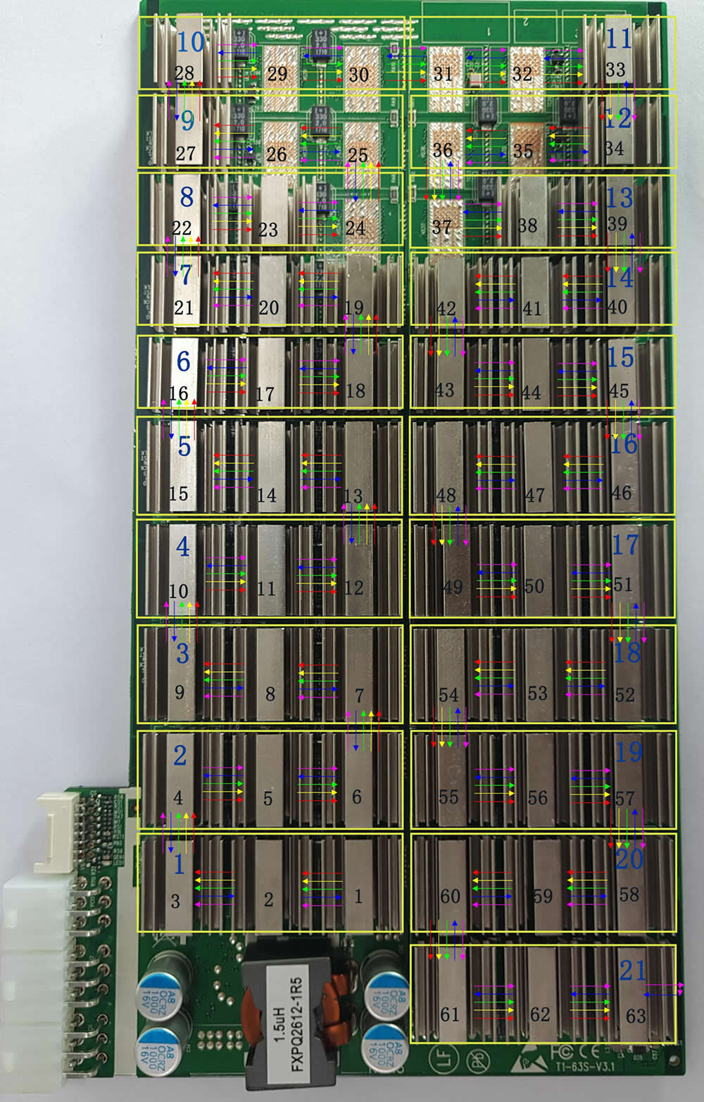
figure 1
Test whether the SPI waveform of the error‑reporting chip is normal.
1. Each yellow box in the figure is a voltage domain, a total of twenty one Voltage domains, each voltage domain is on average 0.42V.
2. The black numbers represent the order and bit number of the chip.
3. The red arrow in the figure shows CLK Signal direction.
The yellow arrow shows the direction of the SCK signal;
The green arrow shows the direction of the CS signal;
The blue arrow shows the direction of the DI signal;
The purple arrow shows the direction of the DO signal.
4. There is between every two chips 1‑7 Test point 1 for CLK Signal; test point 2 for RST Signal; test point 3 for EN Signal; test point 4 for SCK Signal; test point 5 for CS Signal; test point 6 for DI Signal; test point 7 for DO signal.
DI signal flow direction, from No. 63 chip to 1 Return the chip number, and then return to the control board;
DO signal flow direction, by 1 No. chip pulls low level toward 63; not plugged in IO Line, standby 0V , When calculating 0.3 Pulse signal around.
The RST signal flows in from the control board, and then by 1 Chip to 63 No. chip transmission.
2.2 The figure below shows the key circuits on the front of the T1 hash board.
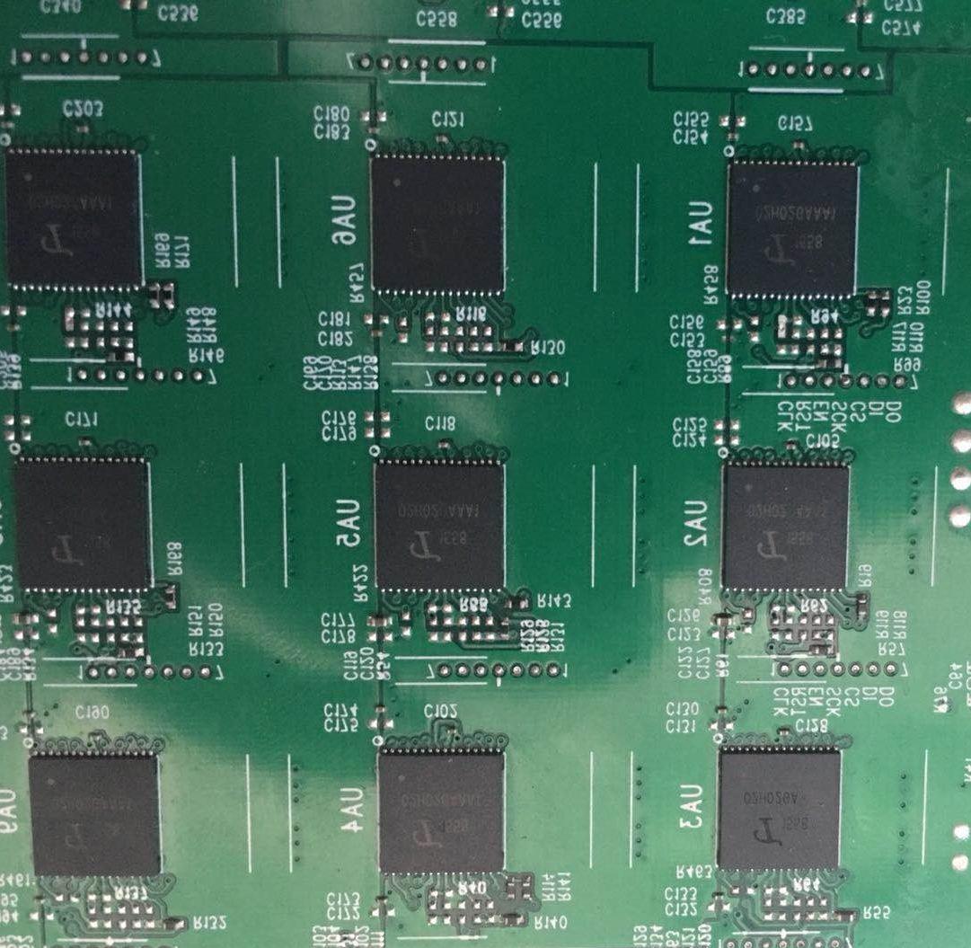
figure 2
1). Test points between each chip (as shown in the figure after zooming in): Figure 2
Figure 2. When repairing test points between chips, the test points between test chips are the most direct way to locate faults. The arrangement of the test points of the T1 arithmetic board is: CLK, RST.EN, SCK, CS, DI, DO signals.
Figure 1. Signal trend
2) Voltage domain: The whole board has 21 voltage domains, and each voltage domain has 3 chips. The three chips in the same voltage domain are powered in parallel, and then connected in series with other voltage domains after being connected in parallel. The circuit structure is shown in Figure 4 below:
Principle analysis of voltage domain single chip (see Figure 3 below)
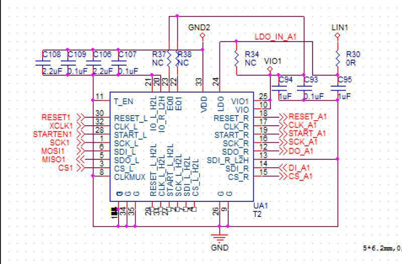
Figure 3
● The above are the functions of each pin of the T1558 chip.
During maintenance, 14 test points before and after the chip are mainly tested (seven points before and after the chip: CLK, RST, EN, SCK, CS, DI, DO); DCDC voltage output 8.82V; boost voltage 11V, LDO—1.8 V etc.
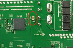
The two ends of the C56 capacitor on the left are the total DCDC output voltage, which should be about 8.82V
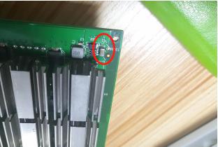
On the left, both ends of the C57 capacitor are the boost voltage, which should be about 11V

Figure 6. BM1558 circuit diagram
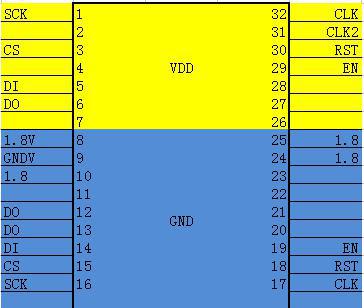
Figure 7. BM1760 chip pins
CLK: 0.9V provided by Y1 12M crystal oscillator;
DO: From the first chip to the last chip provided by the control board, the signal can be measured with an oscilloscope;
DI: Return from the last chip to the first chip, the signal can be measured with an oscilloscope;
SCK: When the control board provides about 0.12V for calculation, the abnormal or low voltage will cause the calculation board to be abnormal or the calculation power is low;
EN: 1.8V Provided by the control board;
CS: Provided by the control board;
RST: 1.8V . Provided by the control board, each time the test key is pressed, a low‑level reset signal will be output again.
When the above‑mentioned test point status and voltage are abnormal, please estimate the fault point based on the circuit before and after the test point.
It can be seen from the chart above:
CLK signal: by the chip 32 Or 31‑pin in, 17‑pin out, when connected across the voltage domain, by 5 Foot out through 100NF The capacitor is connected to the input to the next chip twenty three foot.
DO signal: enter from pin 6 of the chip, 12 Foot out;
DI signal: returned by the chip from pin 5, output from pin 13 or 14;
CS signal: input from pin 3 of the chip and output from pin 15;
RST signal: Input from chip 30 pins, output from 118 pins.
Test the signal voltage of each chip, LDO‑1.8OV
CORE: 0.8V When this voltage is abnormal, it is usually the chip of the voltage domain CORE Short circuit
LDO‑1.8O: 1.8V When this voltage is abnormal, the chip LDO‑1.8O Short circuit or open circuit
3) Judging the operating status of the hash board, the hash rate of the chip, and the temperature sensitivity based on the information in the printing window of the manufacturing tool.
3.3 IO Interface Definition
IO is composed of 2X7 pitch 2.0 PHSD 90 degree in‑line double row.
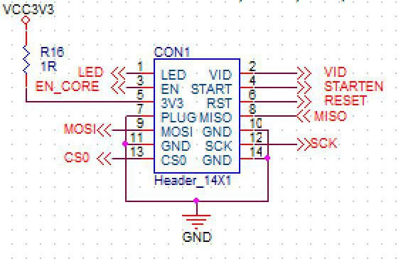
The pin definitions are shown in Figure 8 below:
As shown in FIG:
1 pin is LED
2 pin for VIDD
10, 14 pin: for GND .
3 pin are EN
4 pin for STAR
7 pin is PLUG
12 pin for SCK
13 pin are CS
8.9 pin (DI, EO)
6 pin ( RST ): is the reset signal 3.3V Terminal, after being divided by resistors, it becomes 1.8V RST Reset signal.
5 pin ( 3V3 ): is the hash board 3.3V Power supply, the 3.3V Provided by the control board, mainly for PIC Provide working voltage.
Figure 8. IO Definition of each pin
TX_IN voltage is 1.8V
RST_IN voltage is 1.8V
4. Routine maintenance process:
● Reference steps:
1. Routine inspection: First, perform visual inspection on the arithmetic board to be repaired to observe whether there is any displacement, deformation, or scorching of the small heat sink? If any, you must deal with it first; if the small heat sink is displaced, remove it first, wash off the original glue, and re‑adhesive after the repair is passed.
Secondly, after the visual inspection is no problem, the impedance of each voltage domain can be tested first to detect whether there is a short circuit or an open circuit. If you find out, you must deal with it first.
Thirdly, check whether the voltages in each voltage domain reach 0.4v, and the voltage difference between the voltage domains must not exceed 0.05. If the voltage in a voltage domain is too high or too low, the circuits in the adjacent voltage domain generally have abnormal phenomena, and it needs to find the reason first.
2. After the routine detection is no problem (generally, the short‑circuit detection of the routine detection is necessary, so as not to burn the chip or other materials due to the short circuit when the power is turned on), you can Use DEBUG connection for chip detection, and judge and locate according to the detection result.
3. According to the display results of the test and detection, starting from the vicinity of the faulty chip, check the chip test points (CLK, RST, EN, SCK, CS, DI, DO); DCDC voltage output 8.82V; boost voltage 11V, LDO‑‑ 1.8V etc.
4. Then according to the signal flow direction, except for DI signals, the signals are transmitted in the reverse direction (chips 6 to 1). Several of the signals CLK, RST, EN, SCK, CS, DO are forward transmission (1-63), and abnormalities are found through the power supply sequence the point of failure.
5. When locating the faulty chip, the chip needs to be welded again. The method is to add flux around the chip (preferably no-clean flux), heat the solder joints of the chip pins to a dissolved state, move gently up and down, left and right to press the chip; prompting the chip pins and pads Re-melt and collect tin. In order to achieve the effect of tinning again. If the fault remains the same after re-soldering, you can directly replace the chip.
6. The repaired arithmetic board must be tested twice or more during testing. Two test times before and after: for the first time, after the replacement of parts is completed, the hash board needs to be cooled down, and after passing the test, put it aside first. For the second time, after a few minutes wait for the arithmetic board to cool down completely, perform the test again. Although the time for the two tests is a few minutes, this does not affect the work. Put the repaired board aside, continue to repair the second board, wait for the second board to be repaired and set it aside to cool down, and then test the first board. In this way, the time is just staggered, and the total time is not delayed.
7. The repaired board. It is necessary to classify the faults and make records of the type, location, reason, etc. of the replacement components. For feedback back to production and after‑sales, Research and development.
8. After recording, install it into a complete miner for formal aging.
5. Failure types:
1. The impedance of each voltage domain is unbalanced; when the impedance of certain voltage domains deviates from the normal value, it indicates that there are parts in the abnormal voltage domain that have open circuits and short circuits. It is most likely to be caused by general chips. But there are three chips in each voltage domain, and often only one has a problem when it fails. The method of finding out the problem chip can detect and compare the abnormal point through the test point to ground impedance of each chip. If you encounter a short-circuit phenomenon, you can first remove the heat sink on the chip with the same voltage, and then observe whether the chip pins are connected to the solder. If the short-circuit point cannot be found in the appearance, the short-circuit point can be found according to the resistance method or the current interception method.
2. Voltage imbalance in the voltage domain; When the voltage of some voltage domains is too high or too low, it is generally because of abnormal voltage domains or adjacent voltage domains that there are abnormal signals, resulting in abnormal working status of the next or next voltage domain and voltage imbalance . The abnormal point can be found only by detecting the signal and voltage of each test point. Individually, it is necessary to find out the abnormal point by comparing the impedance of each test point.
Observe the appearance, measure the impedance, measure the voltage, and check the voltage and power supply of each test point. The test locates the chip according to the test information, first re-soldering, and re-soldering is invalid. The fault type is recorded and tested for more than two times. Ok can be considered as repaired, and then related aging.
Pay special attention to the fact that the CLK signal and RST Signal, these two abnormalities are most likely to cause voltage imbalance.
3. Lack of chips: The lack of chips means that the test box fails to detect all 63 chips, often only as many as the actual number of chips. However, the actual missing (undetected) abnormal chip is not in the displayed position. At this time, it is necessary to accurately locate the abnormal chip through testing. The location method can use TX cut-off to send out the way to find the location of the abnormal chip. It is to connect the TX signal of a certain chip to the ground. For example, after outputting the TX signal of the 50th chip to the ground of the voltage domain, theoretically if all the previous chips are normal, 50 chips should be detected in the test box? If 50 chips are not detected, the abnormality is before the 50th chip; if 50 chips are detected, the abnormality is after the 50th chip. By analogy, use the dichotomy to find the location of the abnormal chip.
4. Broken chain:
A broken chain is similar to lack of chips, but in a broken chain, not all chips that cannot be found are abnormal, but all the chips after the abnormal chip are invalid due to a certain chip abnormality. For example, a chip itself can work, but it will not forward other chip information; at this time, the entire signal chain will come to an abrupt end, and lose a large part of it, which is called broken chain. Generally the broken chain can be displayed by the test box. For example, when the test box detects the chips, only 14 chips are detected. If the number of preset chips is not detected in the test box, it will not run, so it will only display how many chips are detected, at this time, according to the displayed number «14», the problem can be found by detecting the voltage and impedance of each test point before and after the 14th chip.
5. Not running:
No running means that the test box cannot detect the chip information of the hash board, but displays NO hash board; this phenomenon is the most common and the fault range involved is also wide.
1) Non‑operation caused by abnormal voltage in a certain voltage domain; the problem can be found by measuring the voltage of each voltage domain.
2) The abnormality caused by a certain chip abnormality can be found by measuring the signal of each test point.
CLK signal: the signal is generated by 1 No. chip output to 63 No. chip, but the current version has only two crystal oscillators, Y1(1‑30) X1(31‑63) of which as long as there is an abnormal signal clk Yes, all the following signals will be abnormal, search in order according to the signal transmission direction.
DO signal: This signal is caused by 1 , 2 , 3 ,,,,, 63 No. chip, when a certain point of the dichotomy is abnormal, it can be detected forward.
DI signal: This signal is returned by No. 63.60, 59, 58, and 1, and the cause of the fault is confirmed through the chip signal direction. This signal is the highest priority if the T1 operation board is not running, and the signal is searched first.
RST signal: 1.8V ; After the arithmetic board is powered on and the 14P signal is plugged in, this signal will change from 01 , 02 ,,,,,, 0 63 The direction of the transmission to the last chip.
3) A certain chip VDD It can be caused by measuring whether the potential difference of each voltage domain is normal. Under normal circumstances, when the VDD voltage is 0.42, the normal voltage of each test point in other voltage domains is also 0.42 to ensure the balance between the voltage domains.
4) of a certain chip VDD1V8 Abnormal voltages Determine whether a certain VDD1V8 voltage is normal by measuring the test points of each voltage. Generally, the LDO voltage determines the voltage of each test point. When the LDO voltage is 1.8V, the normal voltage of each test point in other voltage domains is also 1.8. V
5. Low hash rate:
Low hash rate can be divided into:
1) During the test, received Nonce Insufficient, lack of hash rate and show bad phenomena. This phenomenon can be judged by seeing the number of nonce returned by each chip directly through the serial port printing information. Generally, the chip with the returned nonce number lower than the set value should be trouble‑shooted, and the non‑welding and external causes can be directly replaced. .
2) When the test fixture was tested, the hash rate was low after the whole miner was installed. Most of this situation is related to the heat dissipation conditions of the chip, and special attention should be paid to the glue used for the small heat sink of each chip and the ventilation performance of the whole miner. Another reason is that the voltage of a certain chip is critical. After the whole miner is installed, the difference between the 12V power supply and the power supply during the test causes the test calculation power to deviate from the running calculation power. You can use the test box to test after turning it down, and adjust it slightly. After the 12V output of the voltage DC adjustable power supply, perform the test again and find out the voltage domain with the lowest number of returned nonces.
6. A certain chip NG:
Refers to when the test is passed, the test serial port information shows that the returned nonce of a certain chip is insufficient or zero. In addition to eliminating the problem of false soldering and peripheral components, you can Replace the chip directly.
● Maintenance instructions:
1. During maintenance, the maintenance personnel must be familiar with the function and flow direction of each test point, the normal voltage value and the ground impedance value.
2. You must be familiar with chip soldering to avoid blistering and deformation of the PCB or damage to the pins.
3. T1558 chip package, 16 pins on both sides of the chip. The polarity and coordinates must be aligned during welding and they must not be misaligned.
4. When replacing the chip, the thermally conductive fixing glue around the chip must be cleaned to prevent the chip from being damaged by the hanging or poor heat dissipation when the IC is soldered.
после IP адреса асика добавляем:
/error — код ошибки на устройстве с описанием ошибки
/logs — системный лог
/mtest — тестирование платы
/mlogs — лог cgminer’a
/stat — графическая карта чипов с hw,temp и прочим
/fan — настройка оборотов кулеров
получается пример:
http://192.168.1.10/logs
Заметки от ребят:
Сообщение с вложенными прошивками:
Изменено 24 Января 2022 пользователем Pavel38
обновление
Код Расшифровка ошибки
0 ОК
21 1 или более хеш-плат не обнаружены
22 Аномальная связь по управлению питанием
23 Все хэш-платы не могут быть включены
24 Некоторые платы не включаются
25 Не удалось поднять частоту хэш-платы
26 Не удалось установить напряжение
27 Тест чипа BIST не пройден
28 Ненормальная связь платы хешрейта не может быть автоматически восстановлена во время работы
29 Ненормальная связь по питанию во время работы не может быть восстановлена автоматически
30 Подключение к майнинговому пулу прервано
31 Повреждение отдельных микросхем, что приводит к искусственно завышенной вычислительной мощности
32 Hashboard перегрелся
33 Невозможно прочитать температуру чипа
34 Неправильное подключение кабеля связи платы управления
35 Аномальный источник питания
36 Некоторые чипы не работают должным образом
37 Тип платы управления / версия прошивки / количество микросхем не совпадает
38 Наконец, у некоторых чипов низкая вычислительная мощность.
39 Аномальные параметры старения
40 Проверьте, совпадают ли направления переднего и заднего ветра, согласуются ли они с другими машинами, и если они не совпадают, измените направление вентилятора.
41 Измерьте температуру воздухозаборника горной машины. если она превышает 40 градусов, необходимо улучшить температурную обстановку в шахте.
42 Если определенная плата вычислительной мощности часто перегревается, проблемную плату вычислительной мощности можно заменить (ремонт головоломки).
43 Ошибка, не удается прочитать температуру чипа, не удается прочитать температуру чипа, номер платы вычислительной мощности»1.Проверьте, не ослаблены ли винты на обоих концах клеммы питания и подключения кабеля SPI
44 Замените источник питания
45 Замените плату управления
46 Замените проблемную плату вычислительной мощности (ремонт головоломки)
47 Ошибка включена, неверное подключение кабеля связи платы управления, неправильное подключение кабеля SPI платы управления, номер платы вычислительной мощности «1.Проверьте, соответствует ли способ (последовательность) подключения кабеля SPI платы вычислительной мощности другим машинам той же модели
48 Замените плату управления»
49 Ошибка, неправильный источник питания, неправильный источник питания,, «1.Обратите внимание, что если нет явных отклонений в вычислительной мощности всей машины (ни одна плата не упала), нет необходимости иметь с этим дело.
50 Проверьте, не ослаблены ли винты на обоих концах клеммы питания и подключения кабеля SPI
51 Замените источник питания»
52 Ошибка, некоторые чипы работают неправильно, и количество ядер на чипе ненормально. Номер платы вычислительной мощности: Номер чипа, «1.Обратите внимание, что если нет явных отклонений в вычислительной мощности всей машины (ни одна плата не упала), нет необходимости иметь с этим дело.
53 Перезапустите майнер, чтобы узнать, по-прежнему ли сообщается о той же ошибке
54 Замените проблемную плату вычислительной мощности (ремонт головоломки)
55 ErrInvVidtype, тип платы управления/версия прошивки/количество микросхем не соответствует, тип платы управления/версия прошивки/количество микросхем не соответствует, «видтип, тип майнера, подтип, номер микросхемы», «После накопления нескольких единиц (>10) обратитесь к разработчику программного обеспечения, чтобы решить эту проблему сразу»
56 ErrBadRearChips, последние несколько чипов имеют низкую вычислительную мощность, а последние несколько чипов имеют низкую вычислительную мощность, в настоящее время не нуждаются в обработке
57 ErrInvTuneParam, параметры старения являются ненормальными, начальная частота старения и напряжение неверны, и в настоящее время старение не нуждается в обработке.
58 ,,,,,
59 ,,,,,»внимание:
60 Каждый раз, когда вы выполняете шаг решения, вам необходимо снова включить питание, чтобы убедиться, что оно вернулось в нормальное состояние.
61 После замены каждой детали, если проблема не решена, замененные детали следует вернуть на исходную машину.
62 Установлено, что отремонтированная плата вычислительной мощности требует добавления кода ошибки и простого описания проблемы».
Troubleshooting mining malfunctions can be complex, yet InnoMonitor provides miners with a tool to quickly and accurately identify faulty parts. By inputting an IP range on Innosilicon’s website and running the batch management scan, issues may arise that require additional research before attempting any repairs or fixes; however, another scan will help confirm abnormalities.
Tracking down the source of an error code
When encountering an error code from a miner, it can be difficult to pinpoint where the fault lies. However, with some understanding of common miner issues and their corresponding error codes, it is possible to locate the fault part accurately.
Restarting the miner is generally a good first step when troubleshooting. This allows for any abnormal conditions to reset and for any malfunctioning parts to be re-engaged or reconnected. To accurately identify faulty parts in a miner, one should first download and open InnoMonitor, a batch management tool. This tool is available on the website of Innosilicon. After opening, input the IP range the miner is associated with and press the “Scan” icon.
If there is an issue with the miner, but no error code is reported, it is necessary to enter the miner log backstage to find the actual error code. To do this, ensure you have opened InnoMonitor and followed instructions up until now. Once you are in the log backstage, observe carefully and take note of any variables or irregularities in comparison to other miners in your system. This could be abnormal fan speeds or temperatures, so pay close attention to data values like these.
If the issue persists, examining the various components of the miner can help identify which parts require attention. For example, if Error Code 30 is encountered (which indicates an inability to connect to the mining pool), checking whether the pool is configured correctly or examining whether the network port of the miner is connected properly are two possible solutions. Similarly, if Error Code 35 (abnormal power output) appears, restarting or replacing the power supply could rectify this issue.
If Error Codes 21 (individual hash boards not detected) or 24 (hash board fault) present themselves, powering off and cooling for 10 minutes before turning back on may resolve these errors temporarily. Additionally, checking that all power supplies and cables are tightly connected can help identify faulty hash boards, which may need replacement to restore the normal operation of the miner. Furthermore, checking that all data cables are connected in proper sequence and making sure screws at both ends of terminals and SPI cable connections are secure should be examined since they can cause unexpected results if loose or broken.
For more complex errors such as chip abnormality (Error Code 31) or voltage difference warnings (Error Code 164), consulting after-sales personnel or replacing particular components like control boards may be necessary.
Although locating faults within miners requires an understanding of specific error codes and potential solutions for each one, anyone familiar with mining processes can identify exactly what needs fixing by following the steps outlined above.
Innosilicon error code definitions
Error Code 32: ErrHighAirTemp – High air temperature, fans may be rotating in different directions
Error Code 30: NoPoolConnection – Unable to connect to the mining pool
Error Code 22, 29: Battery12CCommunicationFailure – Battery 12C communication is abnormal
Error Code 35, 40, 41: AbnormalPowerOutput – Abnormal power output
Error Code 21: IndividualHashBoardsNotDetected – Individual hash boards are not detected
Error Code 23, 24, 27: DataCableConnectionSequenceIncorrect – The data cable connection sequence is incorrect
ErrorCode 31: HashBoardFault1- Hash board fault (individual chip)
ErrorCode 25, 26, 28, 33, 36, 42: HashBoardFault2- Hash board fault (all chips)
ErrorCode 37 : ControlBoardorHashBoardDoesNotMatch- The control board or hash board does not match
ErrorCode 38 : ErrBadRearChips – The last few chips have a low hash rate, it is recommended to replace them
ErrorCode 39 : ErrInvTuneParam- Aging parameter abnormal, initial aging frequency voltage is incorrect
Error Code 41: PSU_STARTUP_VOLT – Startup voltage problem b/p – off for 15 minutes
Error Code 42: SETPLL_PLANB_FAIL – Low frequency on chip
Error Code 43 : VOLT_DIFF_FAIL – Failure, overvoltage on chip
ErrorCode 47 : WATCHDOG – Watchdog reset
ErrorCode 51 : SPI_HighSpeed- Chip overvoltage – drive in low mode
Error Code 52 : CONF_PARA1 – In connected mode, changes pool
ErrorCode 53 : CONF_PARA2 – Use this, a hash is underrated on a board
Error Code 57: PSU_BAD_POWER – B/p insufficient power
ErrorCode 161 : Dec_Power- Underestimate board frequency
ErrorCode 164: VoltAB_Diff_Warn- Voltage difference warning
Conclusion
By understanding the various error codes and their potential solutions, miners can quickly identify which parts of the mining process require attention. Whether it’s an inability to connect to a pool or abnormally low power output, these errors can be solved by following some simple steps outlined in this article. Additionally, complex issues such as chip abnormalities or voltage difference warnings may require consultation with after-sales personnel or replacement of particular components like control boards. With this knowledge in hand, anyone familiar with mining processes should now be able to maintain their miner effectively and efficiently.
-
#1
Есть кто сталкивался и решил проблему на innosilicon Т2Т 30TH, выскакивает ошибка 43. Машинка стоит работает час, два потом график падает и она будто бы заново включается. Бывает что включиться без одной платы, бывает все заработают. Блок питания поменял проблема не решилась.
-
#3
Пишет 43 сам понять не могу ее в списке нет. иногда очень редко бывает что появляется 33 потом пропадает сразу
-
#6
Пишет 43 сам понять не могу ее в списке нет. иногда очень редко бывает что появляется 33 потом пропадает сразу
логи и карту чипов бы скинул.
Ссылки:
/error — код ошибки на устройстве с описанием ошибки
/logs — системный лог
/mlogs — лог cgminer’a
/stat — графическая карта чипов с hw,temp и прочим
/fan — настройка оборотов кулеров
Заходить через вебморду, добавить после http://айпи асика/ТУТ указать то что перечислил выше
-
#7

И иногда ооочень редко проскакивает вот эта ошибка
-
#8
логи и карту чипов бы скинул.
Ссылки:
/error — код ошибки на устройстве с описанием ошибки
/logs — системный лог
/mlogs — лог cgminer’a
/stat — графическая карта чипов с hw,temp и прочим
/fan — настройка оборотов кулеровЗаходить через вебморду, добавить после http://айпи асика/ТУТ указать то что перечислил выше
Сейчас сделаю
-
#11
/logs ничего не показывает
-
#12
/logs ничего не показывает
Наверное прошивка последняя стоит. она не показывает логи. нужно откатить на предыдущую для просмотра логов.
-
#13
Зачем ставить корявый переводчик на веб морду? Он затрудняет поиск ошибок на языке оригинала.
140-137 чипы в красной зоне.

-
#14
Наверное прошивка последняя стоит. она не показывает логи. нужно откатить на предыдущую для просмотра логов.
Подскажи где скачать предыдущую прошивку?
-
#15
Зачем ставить корявый переводчик на веб морду? Он затрудняет поиск ошибок на языке оригинала.
140-137 чипы в красной зоне.
Посмотреть вложение 234677
Гугл сам переводит( есть машинка у которой так же чипы и она работает уже давно без проблем.
Подскажи где скачать предыдущую прошивку?
Могу убрать перевод если так лучше будет разобраться.
-
#17
Гугл сам переводит( есть машинка у которой так же чипы и она работает уже давно без проблем.
Могу убрать перевод если так лучше будет разобраться.
В ошибке и указаны эти чипы на первой хеш плате.

-
#19
получается нужно сначала устранить эту проблему?
Может термоленты рассохлись или что там между радиатором и чипами. Разбирал как то T2TZ, там обрывки лент торчали из платы. В любом случае без логов это гадание на кофейной гуще. Можно ещё замерить мультиметром напряжение сети и вольтаж на клеммах хеш плат, подтянуть их. Если доберешься до логов, скопируй их в .txt и закинь сюда.
-
#20
получается нужно сначала устранить эту проблему?
Добрый день! У меня всё то же самое. и ошибка 43 , и чипы 137-140 красные на второй плате двух T2T 33 Th. Можно ли узнать, удалось ли решить проблему? сегодня принес после ремонта плату, установил, но проблему ремонтник не решил, только денег взял.
1. Download the batch management tool (Inno Monitor Download) to the desktop and open it.
2. Enter the IP range where the miner is located, and click to start scanning.
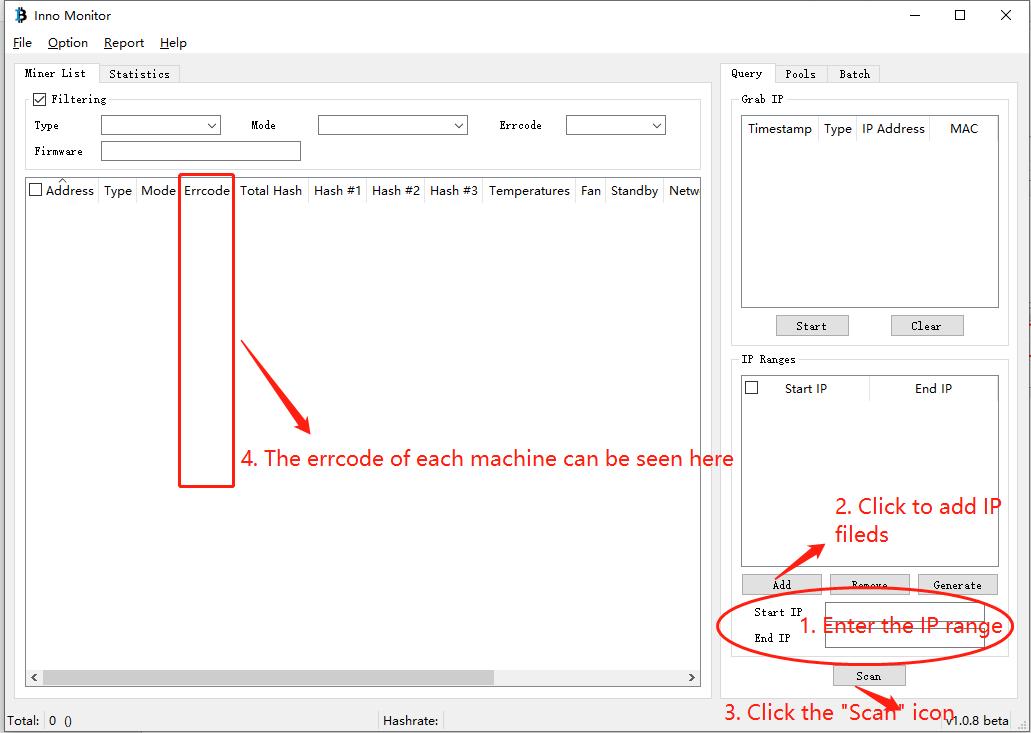
If the miner does have a problem, but the batch tool fails to report an error code, enter the miner log backstage to find the error code. The method is as follows:
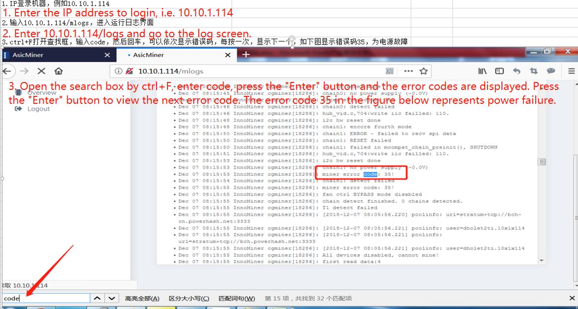 3. Check the miner failure according to the error code and confirm the fault location.
Notice:
(1) Every time you perform a solution step, you need to re-power on to confirm whether it is back to normal
(2) If the problem is not solved after replacing each part, the replaced part should be installed back to the original miner
(3) Make sure that the miner to be repaired requires an error code and a simple description of the problem.
|
Error code |
Question |
Treatment plan |
|
32 |
Over-temperature protection |
① Whether the fan is usually working, and whether the rotation direction of the two fans is the same. If not, change the direction of the fan; If the fan does not rotate, replace the fan first; if the fault persists, the control board or power supply needs to be replaced. ② Whether the temperature of the air inlet of the fan is too high (recommond to use GS320 infrared thermometer), and move the miner to the lower position of the shelf and place it; If it exceeds 40 degrees, the temperature environment of the mining farm must be improved. ③ If a particular hash board is frequently overheated, the problematic hash board can be replaced. |
|
Notes: If the problem occurs massively, the abnormal miner temperature shall be taken into top priority.(i.e. local fan failure) |
||
|
30 |
Unable to connect to the mining pool |
1. Some miners ① Check whether the pool is configured correctly ② Check whether the network port of the miner is tightly connected ③ Exchange network cables with normal ④ Replacing the control board 2. All miners ① Check whether the pool address is configured correctly ② Check whether the operator’s network is interrupted ③ Check the local network setting (such as the setting of DNS,DHCP,ports and other settings) |
|
22、29 |
Battery 12C communication is abnormal |
① Restart ② Replace the power supply, you can choose the Lianli Small Steel Cannon PSU 2500W ③ Replace the control board |
|
35、40、41 |
Abnormal power out put |
① Restart ② Replace the power supply ③ Replace the faulty hash board or control board. ④ Check whether the screws at both ends of the power terminal and the connection of the SPI cable are loose ⑤ Observe the miner’s hash rate. If there is no obvious abnormality (not falling off the board), there is no need to deal with it. |
|
21 |
Individual hash boards are not detected |
① Check the power supply and cable connection of the hash board, and then plug it in again ② Replace the faulty hash board ③ Replace the control board |
|
34 |
The data cable connection sequence is incorrect |
① Replace the control board ② Check whether the data cable and power cable connection sequence are consistent |
|
23、24、27 |
Hash board failure |
① Power off and turn on the miner after cooling for 10 minutes ② Check whether the screws at both ends of the power terminal and the connection of the SPI cable are loose ③ Replace the hash board ④ Replace the control board ⑤ Replace the PSU |
|
25、26、28、33、36、42 |
Hash board failure |
① No treating is needed if the hash rate is normal ② Replace the hash board ③ Check whether the screws at both ends of the power terminal and the connection of the SPI cable are loose ④ Replace the power supply ⑤ Replace the control board |
|
31 |
Individual chip abnormality |
① No treating is needed if the hash rate is normal ② Replace the chip |
|
37 |
The Control board or hash board does not match |
Replace with the specific control board parts for this model of miner |
|
38 |
The last few chips have a low hash rate |
No need to deal with |
|
39 |
Aging initial frequency voltage is incorrect |
No need to deal with |
300
Ошибка обнаружения датчика температуры SM0
Проверьте подключение хэш-платы
301
Ошибка обнаружения датчика температуры SM1
302
Ошибка обнаружения датчика температуры SM2
320
Ошибка связи с датчиком температуры платы SM0
Проверьте, заблокированы ли винты панели управления, проверьте переходную пластину и контакты кабеля
321
Ошибка связи с датчиком температуры платы SM1
322
Ошибка связи с датчиком температуры платы SM2
329
Температура платы управления ошибка связи с датчиком
Замените источник питания
350
Защита от перегрева SM0
Проверьте температуру окружающей среды (рекомендуется использовать инфракрасный термометр GS320).
351
SM1 защита от перегрева
352
SM2 защита от перегрева
360
Температура хэш-платы перегревается
410
SMO обнаружило ошибку eeprom
Проверьте переходную пластину и контакт кабеля
411
SM1 обнаружило ошибку eeprom
412
SM2 обнаружило ошибку eeprom
420
SM0 ошибка синтаксического анализатора eeprom
Обновить прошивку
421
SM1 ошибка синтаксического анализатора eeprom
422
M2 ошибка eeprom синтаксического анализатора
430
Ошибка типа бина микросхемы SM0
431
Ошибка типа бина микросхемы SM1
432
Ошибка типа буфера микросхемы SM2
440
Ошибка SM0 eeprom chip num X
441
Ошибка SM1 eeprom chip num X
442
SM2 номер микросхемы eeprom X ошибка
450
SM0 eeprom xfer error
Проверьте плату адаптера и контакты проводки.Обновите прошивку
451
SM1 eeprom xfer error
452
SM2 eeprom xfer error
510
SM0 ошибка типа майнера
Версия и тип хэшборда несовместимы, замените правильный хэшборд
511
SM1 ошибка типа майнера
512
Ошибка типа майнера SM2
520
Ошибка типа бина SM0
Если тип чипа хэш-платы несовместим, замените правильную хэш-плату
521
Ошибка типа бина SM1
522
Ошибка типа бина SM2
530
Плата SM0 не обнаружена
Проверьте проводку платы адаптера и кабель, или замените плату управления, чтобы проверить, припаян
ли
разъем хэш-платы.
531
Плата SM1 не обнаружена
532
Плата SM2 не обнаружена
540
Количество микросхем SM0 неполное
Проверьте переходную пластину и контакт кабеля
541
Количество микросхем SM1 неполное
542
Количество микросхем SM2 неполное
550
SM0 имеет плохие чипы
Замените плохую микросхему в позиции печати
551
SM1 имеет плохие чипы
552
SM2 имеет плохие чипы
560
SM0 потеря баланса
Подключите переходную пластину, а затем снова прикрутите хэш-плату для подключения питания
561
SM1 потеря баланса
562
SM2 потеря баланса
590
Частота SM0 слишком низкая
Замените хэш-плату и поместите вместе хэш-платы, которые сообщили об одной и той же ошибке
591
Частота SM1 слишком низкая
592
Частота SM2 слишком низкая
600
Слишком высокая температура окружающей среды
Проверьте температуру окружающей среды
610
Если температура окружающей среды слишком высока в режиме высокой производительности, вернитесь в
нормальный
режим
Проверьте температуру окружающей среды, в режиме высокой производительности должна быть ниже 30 ℃.
701
На плате управления отсутствует микросхема поддержки
Обновление соответствующего типа микропрограммы
710
Ошибка платы управления
Обновите до последней версии прошивки
712
Плата управления перезагрузилась как исключение
Обновление последней версии прошивки. Проверьте, правильно ли зафиксирован винт платы управления
800
Ошибка контрольной суммы cgminer
Обновление микропрограммы
801
Ошибка контрольной суммы системного монитора
802
Ошибка контрольной суммы системного монитора
2000
Не настроена информация о пуле
Проверьте конфигурацию пула
2010
Все подключения к пулам майнинга не удались
Проверьте настройки сети или пулов майнинга
2020
Не удалось установить соединение с пулом майнинга
2021
Не удалось установить соединение с пулом майнинга
2022
Не удалось установить соединение с пулом майнинга
2030
Скорость повторного срабатывания пула майнинга слишком высока
Проверьте настройки сети или пула майнинга, а также настройки майнинга криптовалюты
2040
Пул не поддерживает режим asicboost
Проверьте конфигурацию пула
2310
Хэшрейт слишком низкий
Проверьте входное напряжение, сетевое окружение и температуру окружающей среды.
2320
Скорость хэширования слишком низкая
2340
Потеря хэшрейта слишком высока
2350
Потеря скорости хэширования слишком высока
5070
Скорость потока воды SM0 ненормальная
Проверьте, нормальный ли поток воды
5071
SM1 Скорость течения воды ненормальная
5072
SM2 Скорость потока воды ненормальная
5110
SM0 Таймаут повышения частоты
Перезагрузите
5111
SM1 Таймаут повышения частоты
5112
SM2 Таймаут повышения частоты
8410
Ошибка версии программного обеспечения (miner M2x с прошивкой M3x или M3x с прошивкой M2x)
Обновление до правильной версии прошивки
100001
/antiv/signature illegal
Обновление до последней версии микропрограммы или запись карты
100002
/antiv/dig/initd.dig illegal
Обновление до последней версии микропрограммы или запись карты
100003
/antiv/dig/pf_partial.dig illegal
Обновление до последней версии микропрограммы или запись карты

- Manuals
- Brands
- INNOSILICON Manuals
- Computer Hardware
- A4+ LTCMaster
- User manual
-
Contents
-
Table of Contents
-
Bookmarks
Quick Links
A4+ LTCMaster
USER MANUAL
INNOSILICON CONFIDENTIAL
Related Manuals for INNOSILICON A4+ LTCMaster
Summary of Contents for INNOSILICON A4+ LTCMaster
-
Page 1
A4+ LTCMaster USER MANUAL INNOSILICON CONFIDENTIAL… -
Page 2: Table Of Contents
INNOSILICON A4+ LTCMaster High Efficient LTCMaster Table of Contents 1. OVERVIEW 2. MINER ASSEMBLE 2.1 Check the miner before power on 2.2 Connect the PSU 2.3 Connect the Ethernet Cable 3. ENTER THE MINER CONSOLE 4. CONFIG THE MINER 5. APPENDIX 5.1 Modify the login password…
-
Page 3: Overview
A4+ LTCMaster 1. OVERVIEW Part Number A4+ LTCMaster Hash Rate 620Mh/s (+-8% ) Power 750W +/-8% Size (L×W×H) 350mm×125mm×158mm Net Weight 3.83KG (without PSU) Operating Temperature 0-40 ℃ Required rated PSU 1000W or above, 9 * PCI-E 6Pin Network Connection…
-
Page 4: Miner Assemble
A4+ LTCMaster 2. CABLE CONNECTION 2.1 CHECK THE MINER BEFORE POWER ON · Check the warranty sticker is well or not, especially the hashboards PSU port side. If the warranty sticker is damaged when you received the miner, please contact our After-sales.
-
Page 5: Connect The Psu
A4+ LTCMaster 2.2 CONNECT THE PSU Every hash board needs to be inserted with 2 PSU cables, controller only needs 1 PSU cable according to the following image . 2.3 CONNECT THE ETHERNET CABLE Insert one end of the Ethernet cable into the router and the other end into the slot shown in the following…
-
Page 6: Enter The Miner Console
A4+ LTCMaster 3. ENTER THE MINER CONSOLE By default, the miner uses Static IP to access the control webpage of the miner. Input 192.168.1.254 into the browser, then click ‘Enter’ to enter the miner’s control webpage (Chrome is the suggested browser).
-
Page 7
A4+ LTCMaster · Press the OK button twice to confirm the changes.Then modify the IP address of the miner (Do it as the follow step g) to guarantee the miner and the router have the same network segment.Then connect the miner with the router,connect the PC with the router and select the “Obtain the IP address automatically”.Now you can enter the IP through the browser into the control interface… -
Page 8: Config The Miner
A4+ LTCMaster · Press the OK button twice to confirm the changes.Then modify the IP address of the miner (Do it as the follow 4.4) to guarantee the miner and the router have the same network segment.Then connect the miner with the router,connect the PC with the router and select the “Obtain the IP address automatically”.Now you can enter the IP through the browser into the control interface…
-
Page 9
A4+ LTCMaster Password is wrong/error?—Please contact our after-sales people. 4.3 Enter the mining pool’s URL, Worker, password according to the following image, then click .The miner will start mining, and the page will return to the ‘Miner Configuration’ page. It will show the user’s modified setting. -
Page 10
A4+ LTCMaster 4.4 To avoid IP conflict when using 2 or more miners at the same time, the IP address needs to be changed. Enter the network interface shown in the following image, and modify the IP address to you need, then click the “Save”… -
Page 11
A4+ LTCMaster HW: means error in calculating INNOSILICON CONFIDENTIAL… -
Page 12: Appendix
A4+ LTCMaster 5. APPENDIX 5.1 MODIFY THE LOGIN PASSWORD Select the “Administration” interface at System, then you can modify your password. Then click to save your new password. Note: As the factory reset will not reset the password to the default password, you must take care your new password.
-
Page 13
A4+ LTCMaster Build date is the version of the firmware. If your miner build date is before NOV 24,please upgradeyour miner via a TF card. Here is the instruction: http://www.innosilicon.com.cn/api/download.php?url=TF-card-firmware-update-manual-en.pdf If your miner build date is NOV 24 or later, a web upgrade is OK, you can do it as below .
Troubleshooting mining malfunctions can be complex, yet InnoMonitor provides miners with a tool to quickly and accurately identify faulty parts. By inputting an IP range on Innosilicon’s website and running the batch management scan, issues may arise that require additional research before attempting any repairs or fixes; however, another scan will help confirm abnormalities.
Tracking down the source of an error code
When encountering an error code from a miner, it can be difficult to pinpoint where the fault lies. However, with some understanding of common miner issues and their corresponding error codes, it is possible to locate the fault part accurately.
Restarting the miner is generally a good first step when troubleshooting. This allows for any abnormal conditions to reset and for any malfunctioning parts to be re-engaged or reconnected. To accurately identify faulty parts in a miner, one should first download and open InnoMonitor, a batch management tool. This tool is available on the website of Innosilicon. After opening, input the IP range the miner is associated with and press the “Scan” icon.
If there is an issue with the miner, but no error code is reported, it is necessary to enter the miner log backstage to find the actual error code. To do this, ensure you have opened InnoMonitor and followed instructions up until now. Once you are in the log backstage, observe carefully and take note of any variables or irregularities in comparison to other miners in your system. This could be abnormal fan speeds or temperatures, so pay close attention to data values like these.
If the issue persists, examining the various components of the miner can help identify which parts require attention. For example, if Error Code 30 is encountered (which indicates an inability to connect to the mining pool), checking whether the pool is configured correctly or examining whether the network port of the miner is connected properly are two possible solutions. Similarly, if Error Code 35 (abnormal power output) appears, restarting or replacing the power supply could rectify this issue.
If Error Codes 21 (individual hash boards not detected) or 24 (hash board fault) present themselves, powering off and cooling for 10 minutes before turning back on may resolve these errors temporarily. Additionally, checking that all power supplies and cables are tightly connected can help identify faulty hash boards, which may need replacement to restore the normal operation of the miner. Furthermore, checking that all data cables are connected in proper sequence and making sure screws at both ends of terminals and SPI cable connections are secure should be examined since they can cause unexpected results if loose or broken.
For more complex errors such as chip abnormality (Error Code 31) or voltage difference warnings (Error Code 164), consulting after-sales personnel or replacing particular components like control boards may be necessary.
Although locating faults within miners requires an understanding of specific error codes and potential solutions for each one, anyone familiar with mining processes can identify exactly what needs fixing by following the steps outlined above.
Innosilicon error code definitions
Error Code 32: ErrHighAirTemp – High air temperature, fans may be rotating in different directions
Error Code 30: NoPoolConnection – Unable to connect to the mining pool
Error Code 22, 29: Battery12CCommunicationFailure – Battery 12C communication is abnormal
Error Code 35, 40, 41: AbnormalPowerOutput – Abnormal power output
Error Code 21: IndividualHashBoardsNotDetected – Individual hash boards are not detected
Error Code 23, 24, 27: DataCableConnectionSequenceIncorrect – The data cable connection sequence is incorrect
ErrorCode 31: HashBoardFault1- Hash board fault (individual chip)
ErrorCode 25, 26, 28, 33, 36, 42: HashBoardFault2- Hash board fault (all chips)
ErrorCode 37 : ControlBoardorHashBoardDoesNotMatch- The control board or hash board does not match
ErrorCode 38 : ErrBadRearChips – The last few chips have a low hash rate, it is recommended to replace them
ErrorCode 39 : ErrInvTuneParam- Aging parameter abnormal, initial aging frequency voltage is incorrect
Error Code 41: PSU_STARTUP_VOLT – Startup voltage problem b/p – off for 15 minutes
Error Code 42: SETPLL_PLANB_FAIL – Low frequency on chip
Error Code 43 : VOLT_DIFF_FAIL – Failure, overvoltage on chip
ErrorCode 47 : WATCHDOG – Watchdog reset
ErrorCode 51 : SPI_HighSpeed- Chip overvoltage – drive in low mode
Error Code 52 : CONF_PARA1 – In connected mode, changes pool
ErrorCode 53 : CONF_PARA2 – Use this, a hash is underrated on a board
Error Code 57: PSU_BAD_POWER – B/p insufficient power
ErrorCode 161 : Dec_Power- Underestimate board frequency
ErrorCode 164: VoltAB_Diff_Warn- Voltage difference warning
Conclusion
By understanding the various error codes and their potential solutions, miners can quickly identify which parts of the mining process require attention. Whether it’s an inability to connect to a pool or abnormally low power output, these errors can be solved by following some simple steps outlined in this article. Additionally, complex issues such as chip abnormalities or voltage difference warnings may require consultation with after-sales personnel or replacement of particular components like control boards. With this knowledge in hand, anyone familiar with mining processes should now be able to maintain their miner effectively and efficiently.
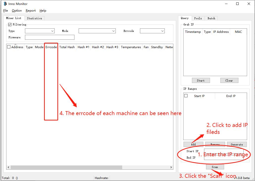
1. Download the batch management tool to the desktop and open it. The download link is:
http://www.innosilicon.com.cn/download/InnoMonitor_x64%20v1.0.8_beta.rar
2. Input the IP range to which the miner belongs and click the «Scan» icon.
If the miner does have a problem, but the batch tool fails to report an error code, enter the miner log backstage to find the error code. The method is as follows:
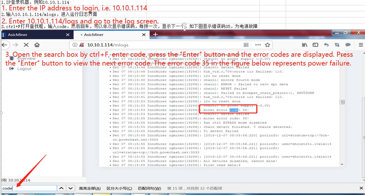
3. Check the miner failure according to the error code and confirm the fault location.
Notice:
1. The miner shall be powered on again to see whether it becomes normal each time you perform one resolution step.
2. The replaced part shall be reinstalled on the original miner once again after replacing the part but with the default unsettled.
|
Error code |
Problem Description |
Suggestion |
|
32 |
Over-temperature protection |
① Whether the fan is usually working, and whether the rotation direction of the two fans is the same ② Whether the temperature of the air inlet of the fan is too high and move the miner to the lower position of the shelf |
|
Notes: If the problem occurs massively, the abnormal miner temperature shall be taken into top priority (i.e. local fan failure). |
||
|
30 |
Unable to connect to the mining pool |
1. Some miners ① Check whether the pool is configured correctly ② Check whether the network port of the miner is tightly connected ③ Exchange network cables with normal ④ Replacing the control board 2. All miners ① Check whether the pool address is configured correctly ② Check whether the operator’s network is interrupted ③ Check the local network setting (such as the setting of DNS,DHCP,ports and other settings) |
|
22、29 |
Battery 12C communication is abnormal |
① Restart ② Replace the power supply, you can choose the Lianli Small Steel Cannon PSU 2500W ③ Replace the control board |
|
35、40、41 |
Abnormal power out put |
① Restart ② Replace the power supply ③ Make sure the screws at both ends of the power terminal and the SPI cable connection are not loose. |
|
21 |
Individual hash boards are not detected |
① Check the power supply and cable connection of the hash board, and then plug it in again ② Put the faulty hash boards into one miner or several miners |
|
Notes: The problem may be caused by setting up the miners and removing them off the shelf violently. Please consult the after-sales personnel before returning the faulty hash boards which are put together into one or several miners. Failure to do so many result in damage to the miner or delay in repairs. |
||
|
34 |
The data cable connection sequence is incorrect |
① Restart ② Check whether the data cable and power cable connection sequence are consistent ③ Replace the control board. |
|
23、24、27 |
Hash board fault |
① Power off and turn on the miner after cooling for 10 minutes ② Replace the hash board |
|
Notes: Please consult the after-sales personnel before returning the faulty hash boards which are put together into one or several miners. Failure to do so many result in damage to the miner or delay in repairs. |
||
|
25、26、28、33、36、42 |
Hash board fault |
① No treating is needed if the hash rate is normal ② Replace the hash board ③ Restart the miner and see if the same error still occurs. |
|
31 |
Individual chip abnormality |
① No treating is needed if the hash rate is normal ② Replace the chip |
|
37 |
The Control board or hash board does not match |
Replace with the specific control board parts for this model of miner |
38 — ErrBadRearChips (the last few chips have a low hash rate, it is recommended to replace them)
39 — ErrInvTuneParam (Aging parameter abnormal, initial aging frequency voltage is incorrect)
41 — PSU_STARTUP_VOLT (startup voltage problem b/p — off for 15 minutes)
42 — SETPLL_PLANB_FAIL (low frequency on chip)
43 — VOLT_DIFF_FAIL (failure, overvoltage on chip)
47 — WATCHDOG
51 — SPI_HighSpeed (chip overvoltage) — drive in low mode
52 — CONF_PARA1 (in connected mode — changes pool)
53 — CONF_PARA2 (use this — a hash is underrated on a board)
57 — PSU_BAD_POWER (b/p insufficient power)
161 — Dec_Power (underestimate board frequency)
164 — VoltAB_Diff_Warn (Voltage difference warning)
About products purchase, please contact our sales manager:![]() [email protected]
[email protected]
About miner repair and after-sale issues, please contact the repair manager email:![]() [email protected]
[email protected]
For business cooperation, please contact:![]() [email protected]
[email protected]
COMPLAINTS & SUGGESTIONS
If you have any dissatisfaction during the transaction or have valuable suggestions for us, please contact us via this email address:![]() [email protected]
[email protected]
Attention!
Recently, many companies claiming to be mining companies imitate us and say that they are related to us, or that they are our branch companies, which has caused customers to be deceived. Please be careful not to believe any impostors, please check our correct contact information and beware of being deceived getting scammed, and losing money.
please check our right contact way:
Here
CLOSE
