
-
#21
Считай ошибки, что гадать
самостоятельно как это сделать?

-
#22
Если не изменяет память
Вставить перемычку к крайние 2 контакта диагностического разъема
Включить полный привод и блокировку
Включить зажигание
На табло высветится SC это сохраненные ошибки, AC активные ошибки
Если будет 00 ошибок нет
[DOUBLEPOST=1428436865,1428436730][/DOUBLEPOST]Парни в мануале все это есть, прочтите на досуге от корки до корки.
Кстати есть возможность перевести весь сервис мануал на русский, но это потребует небольших финансовых затрат если интересно можем скинутся и я сделаю

-
#23
Парни привет, подскажите пожалуйста, когда глушу кота 700 моргает ошибка сначала Р0635, потом она гаснет и появляется EFI, только купил технику, что может быть? подскажите
Присоединяюсь к вопросу. С ошибкой 0635 понятно ( усилитель) а что EFI значит и что делать для устранения
-
#24
Присоединяюсь к вопросу. С ошибкой 0635 понятно ( усилитель) а что EFI значит и что делать для устранения
EFI появляется когда есть какая-либо ошибка. Т.е. надо либо в сервис, либо считывать ошибки и самому разбираться.
-
#25
Кто знает что за ошибка EC 0.0 или что это вообще, сначала выскочила EFI? замкнул два провода и вылезло это?
-
#26
Привет, кто знает значение ошибок sc 1.2 и sc1.3. Когда включаю зажигание насос качает бенз, но давление держит после накачки не больше секунды. То есть заводить приходиться прям в процессе накачки. Померил давление после бензонасоса, все в норме 3.2 очка. Почему не держится не пойму, где клапан есть который должен некоторое время держать давление после включения зажигания???
-
#27
Привет, кто знает значение ошибок sc 1.2 и sc1.3. Когда включаю зажигание насос качает бенз, но давление держит после накачки не больше секунды. То есть заводить приходиться прям в процессе накачки. Померил давление после бензонасоса, все в норме 3.2 очка. Почему не держится не пойму, где клапан есть который должен некоторое время держать давление после включения зажигания???
Клапан находится на пластиковой колбе для насоса (круглый металлический, защелкивается пластиковой крышкой). У меня такое было, спрашивал у всех совет. Совет был один- продуть клапан. У меня не вышло, он то держал, то лил и квадр заводился с 3-5 раза. отдельно клапан я не нашел, а насос в сборе с клапаном стоит доХ.
Поступил кардинально, заглушил клапан, врезал в крышку фитинг для обратки и поставил снаружи фильтр с обратным клапаном от фольсвагена и шланг на обратку. Работает отлично.
-
#28
Клапан находится на пластиковой колбе для насоса (круглый металлический, защелкивается пластиковой крышкой). У меня такое было, спрашивал у всех совет. Совет был один- продуть клапан. У меня не вышло, он то держал, то лил и квадр заводился с 3-5 раза. отдельно клапан я не нашел, а насос в сборе с клапаном стоит доХ.
Поступил кардинально, заглушил клапан, врезал в крышку фитинг для обратки и поставил снаружи фильтр с обратным клапаном от фольсвагена и шланг на обратку. Работает отлично.
А что за фильтр такой? Я знаю что клапан там есть, но обычно когда он не работает, то не работает и квадрик и давление либо маленькое либо большое. А тут прям все в норме, но давляк не держится и секунду. Буду разбирать, смотреть. Про фильтр по подробнее поделись? Думал о таком, но не знал где взять.:Drinks:
-
#29
Топливный фильтр UFI 31.832.00


Артикул: 31.832.00
Производитель: UFI

Италия
Параметры:
- Наружный диаметр 1 [мм]: 61
- Внешний диаметр [мм]: 55
- Впускн. ? [мм]: 8
- Выпускн.-? [мм]: 8
- Высота [мм]: 164
- Давление открытия обгонного клапана [бар]: 3
ТИПО ТАКОГО, они все стоят в районе 1000-1300 руб.
А по работе, я вынимал колбу всю и пихал в пластиковую пятилитровую канистру и смотрел как работает. Ставил обычный манометр водяной на шланг. При включении зажигания насос должен дать 3-5 атм, лишнее сбросить через клапан и давление должно остаться в районе 3 атм и ОЧЕНЬ медленно снижаться. У меня сбрасывал сразу до 0. Поэтому заводился раза с 5-ого. Потом работал нормально, но меня это достало.

-
#30
Клапан находится на пластиковой колбе для насоса (круглый металлический, защелкивается пластиковой крышкой). У меня такое было, спрашивал у всех совет. Совет был один- продуть клапан. У меня не вышло, он то держал, то лил и квадр заводился с 3-5 раза. отдельно клапан я не нашел, а насос в сборе с клапаном стоит доХ.
Поступил кардинально, заглушил клапан, врезал в крышку фитинг для обратки и поставил снаружи фильтр с обратным клапаном от фольсвагена и шланг на обратку. Работает отлично.
Сергей, здравствуйте.
Стал мозги колупать клапан этот. то вообще не пропускает и тогда давление 5,5, то давление до 2-х падает
Отдельно не найти действительно(
Скажите, как Ваша система? Стабильно работает до сих пор?
-
#31
А что означает . Speed sensor. То что в переводе датчик скорости это мне понятно. Как на это реагировать?
-
#32
Сергей, здравствуйте.
Стал мозги колупать клапан этот. то вообще не пропускает и тогда давление 5,5, то давление до 2-х падает
Отдельно не найти действительно(
Скажите, как Ваша система? Стабильно работает до сих пор?
Да, все отлично работало пару лет. Сейчас квадр продан другому человеку. Проблем не высказывает.
-
#33
Парни подскажите вылезла ошибка АС32 заменил бензонасос, промыл форсунку — не заводится и не могу скинуть ошибку . TRV 700 12 года пробег 2700 я первый владелец

-
#34
Смотри провода тонкие к форсунке и датчикам инжектора. Они с виду могут быть нормальные, а внутри жила обломана.
-
#36
Смотри провода тонкие к форсунке и датчикам инжектора. Они с виду могут быть нормальные, а внутри жила обломана.
Действительно провод на форсунку который выходит из жгута был короткий и натянутый, следствие лопнули жилы . Все по чинил Спасибо за быстрый ответ и за подсказку!
-
#38
Добрый день, подскажите пожалуйста как убрать ошибку на котике 700 пишет belt на щитке приборов и перезагружает ее постоянно
-
#39
Скорее всего хана приборке..
-
#40
Belt это ремень, как сбросить эту ошибку.?
Считать код ошибки можно и не имея дорогостоящего сканера, по морганию лампочки EFI. Для этого три раза нужно повернуть ключ зажигания на вкл-выкл. Поворачиваем ключ в положение вкл, ждем пока накачает насос, потом быстро без пауз выкл-вкл-выкл-вкл.
№ Код Описание возможной неисправности 1 Р0030 Обрыв в цепи нагревателя датчика кислорода 2 Р0031 Замыкание на массу в цепи нагревателя датчика кислорода первого цилиндра 3 Р0037 Замыкание на массу в цепи нагревателя датчика кислорода второго цилиндра 4 Р0032 Замыкание на «+» в цепи нагревателя датчика кислорода первого цилиндра 5 Р0038 Замыкание на «+» в цепи нагревателя датчика кислорода второго цилиндра 6 Р0053 Внутреннее сопротивление нагревателя датчика кислорода не соответствует норме 7 Р0105 Нет изменений сигнала с датчика давления воздуха на впуске (старение, засорение или замораживание влаги в датчике) 8 Р0106 Ошибочный сигнал с датчика давления воздуха на впуске ( утечка воздуха через датчик или места подсоединения, выход его из строя, проблема с проходом воздуха в датчик) 9 Р0107 Замыкание на массу в цепи датчика давления воздуха на впуске (слишком низкий уровень сигнала — для BOSCH; слишком низкий уровень сигнала с Т-МАР датчика — для DELPHI) 10 Р0108 Замыкание на «+» в цепи датчика давления воздуха на впуске (слишком высокий уровень сигнала — для BOSCH; слишком высокий уровень сигнала с Т-МАР датчика — для DELPHI) 11 Р0112 Слишком низкое напряжение сдатчика температуры воздуха на впуске (замыкание на массу) 12 Р0113 Замыкание на «+» в цепи датчика температуры воздуха на впуске (слишком высокий уровень сигнала) 13 Р0116 Сигнал сдатчика температуры двигателя ошибочный 14 Р0117 Напряжение сигнала с датчика температуры двигателя слишком низкое (замыкание на массу) 15 Р0118 Напряжение сигнала с датчика температуры двигателя слишком высокое (перемычка на какую-то цепь питания) 16 Р0122 Слишком низкое напряжение с датчика положения заслонки (замыкание на массу) 17 Р0123 Слишком высокое напряжение с датчика положения заслонки (перемычка на какую-то цепь питания) 18 Р0130 Не соответствует норме сигнал с датчика кислорода (нарушение контакта в разъёме или перемычка с цепью нагревателя) 19 Р0131 Слишком низкое напряжение с датчика кислорода первого цилиндра (замыкание на массу) 20 Р0137 Слишком низкое напряжение с датчика кислорода второго цилиндра (замыкание на массу) 21 Р0132 Слишком высокое напряжение в сигнальной цепи датчика кислорода первого цилиндра (если ECU видит напряжение с него постоянно более 1,5 V, то считает это как замыкание на «+») 22 Р0138 Слишком высокое напряжение в сигнальной цепи датчика кислорода второго цилиндра (если ECU видит напряжение с него постоянно более 1,5V, то считает это как замыкание на «+») 23 Р0133 Старение датчика кислорода (переход ECU на усреднённые данные для работы системы впрыска, датчик увеличил время отклика, заменить датчик) 24 Р0134 Ошибочный сигнал сдатчика кислорода (если при запуске двигателя ECU видит, что напряжение с него постоянно остаётся в диапазоне 0,4- 0,6V, то считает это как замыкание на «+») 25 Р0170
| Самообучающаяся система управления впрыском расценивает работу цепи контроля за смесеобразованием как некорректную. | Появление данных кодов корректно |
26 Р0171
| Самообучающаяся система управления впрыском расценивает работу цепи контроля над смесеобразованием как «беднит». | только в том случае, если отсутствуют какие-либо ошибки в системе |
27 Р0172
| Самообучающаяся система управления впрыском расценивает работу цепи контроля над смесеобразованием как «богатит». | управления впрыском. |
28 Р0201 Обрыв в цепи форсунки первого цилиндра (нарушение контакта в разъёмах) 29 Р0202 Обрыв в цепи форсунки второго цилиндра (нарушение контакта в разъёмах) 30 Р0230/0231 Сбой в цепи управления топливным насосом 31 Р0232 Перемычка на «+»в цепи управления топливным насосом (перемычка с какой-либо цепью питания) 32 Р0261 Замыкание на массу в цепи управления форсункой 33 Р0262 Перемычка на «+»в цепи управления форсункой (перемычка с какой-либо цепью питания) 34 Р0321 Сбой точки отсчёта датчиком частоты вращения двигателя (напр. изменение взаимного расположения датчика и ротора) 35 Р0322 Нет сигнала от датчика частоты вращения двигателя (напр. короткое замыкание или обрыв) 36 Р0336 Недостоверный сигнал сдатчика положения коленвала 37 Р0337 Низкий уровень сигнала с датчика положения коленвала 38 Р0351 Сбой в управлении цепью зажигания 39 Р0352 40 Р0444 Подтверждённая версия X-MOTO: Обрыв в цепи клапана XX- для BOSCH Обрыв цепи (низкое напряжение) дополнительного реле стартера- для DELPHI 41 Р0445 Подтверждённая версия X-MOTO: Слишком высокое напряжение на дополнительном реле стартера для DELPHI 42 Р0458 Версия X-MOTO: Слишком низкое напряжение на клапан XX — для BOSCH 43 Р0459 Версия X-MOTO: Слишком высокое напряжение на клапан XX — для BOSCH 44 Р0500 Недостоверный сигнал от датчика скорости (при наличии особых условий: напр. включена нейтраль, но движение продолжается) 45 Р0501 Недостоверный сигнал от датчика скорости (обрыв или замыкание в цепи, выход из строя датчика) 46 Р0505 Сбой в цепи регулирования XX 47 Р0506 Частота вращения на холостом ходу ниже заданной (напр. нарушение в работе воздушного клапана XX, нарушение положения упорного винта заслонки, заедание тросика газа, грязь внутри корпуса заслонки или привода) 48 Р0507 Частота вращения на холостом ходу выше заданной (возможные причины: нарушение в работе воздушного клапана XX, нарушение положения упорного винта заслонки, заедание тросика газа, грязь внутри корпуса заслонки или привода, утечка воздуха на впуске) 49 Р0560 Напряжение АКБ необычное 50 Р0562 Слишком низкое напряжение на АКБ 51 Р0563 Слишком высокое напряжение на АКБ 52 Р0602 Неисправность модуля электронного контроля (ECU) 53 Р0627 Обрыв в цепи реле топливного насоса 54 Р0628 Замыкание на массу в цепи реле топливного насоса 55 Р0629 Замыкание на «+» в цепи реле топливного насоса 56 Р0650 Неполадки в цепи MIL Light (Лампы «Check engine») 57 Р0850 Неполадки в цепи запуска двигателя (не может быть запущен на нейтрали) 58 Р1693 Замыкание на «+» в цепи MIL Light (Лампы «Check engine») (Версия X-MOTO: В цепи тахометра слишком низкий уровень сигнала сдатчика положения коленвала — для DELPHI) 59 Р1694 Замыкание на массу в цепи MIL Light (Лампы «Check engine») (Версия X-MOTO: В цепи тахометра слишком высокий уровень сигнала с датчика положения коленвала — для DELPHI) 60 Р2177 Самообучающаяся система управления впрыском расценивает смесь на оборотах выше XX как «Слишком бедная» 61 Р2178 Самообучающаяся система управления впрыском расценивает смесь на оборотах выше XX как «Слишком богатая»
Устанавливается на многие модели мототехники с инжектором.
Delphi MT05 работает на базе процессора Infineon SAK-XC164CM-16F40F с внутренней флеш-памятью 128Кб.
Список техники:
Benelli: BN302, VLM 150, BJ250T-8
Bennche: Bighorn 400, Bighorn 700
Excalibur: UTV700-4, UTV700-5
Geon: Blackster 250 EFI, Daytona 350 EFI, Invader 350 EFI, Issen 250 EFI, Tossa 250 EFI, Tourer 350 EFI
HiSUN: 700 EFI
Jialing: JH200-8
Lifan: LF250-P
Massimo: Alligator 700, MSU-400, MSU-500
Menards: Yardsport YS700, Yardsport YS400, Yardsport UTV 700, Yardsport UTV 400
Qlink: FrontRunner 700 EFI, FrontRunner 400 EFI
S&T (Hyosung): GV250
Speed Gear: Buggy 600, Buggy 800, Force 500 EFI, Force 700 EFI, UTV 700 EFI, UTV 800 EFI
Stels: Trigger 125, UTV 800H, UTV 800V Dominator, S800 Россомаха, 600 Benelli
Supermach: UTV700-BF-TL, UTV400-BF-TL
Wels: ATV 800 EFI
Zongshen: RX3 (ZS250GY-3)
Delphi MT05.2 работает на базе процессора Infineon SAK-XC164CS-32F40BB с внутренней флеш-памятью 256Кб.
Список поддерживаемых ТС с блоками Delphi MT05.2
Список техники:
Benelli: BN600
CF Moto: CF800 U8, CF800 X8, CF800 Z8
Полезная информация
Коды ошибок стелс
Считать код ошибки можно и не имея дорогостоящего сканера,по морганию лампочки EFI. Для этого три раза нужно повернуть ключ зажигания на вкл-выкл. Поворачиваем ключ в положение вкл, ждем пока накачает насос, потом быстро без пауз выкл-вкл-выкл-вкл. Коды ошибок электронной системы впрыска Stels 800 Число DTC Описание DTC Связанная Калибровка HEX DEC
P0107 MAP Низкое напряжение цепи, либо обрыв KsDGDM MAP ShortLow 107 263
Р0108 MAP Высокое напряжение цепи KsDGDM MAP ShortHigh 108 264
Р0112 IAT Низкое напряжение цепи KsDGDM IAT ShortLow 112 274
Р0113 IAT Высокое напряжение цепи, либо обрыв KsDGDM IAT ShortHigh 113 275
Р0117 Низкое напряжение цепи д. темпер, масла/хладагента KsDGDM CoolantShortLow 117 279
Р0118 Высокое напряжение цепи, либо обрыв KsDGDM_CoolantShortHigh 118 280
Р0122 TPS Низкое напряжение цепи, либо обрыв KsDGDM TPS ShortLow 122 290
Р0123 TPS Высокое напряжение цепи KsDGDM TPS ShortHigh 123 291
Р0131 02S 1 Низкое напряжение цепи KsDGDM 02 1 ShortLow 131 305
Р0132 02S 1 Высокое напряжение цепи KsDGDM 02 1 ShortHigh 132 306
Р0031 02S Высокое напряжение цепи нагревателя KsDGDM 02 HeaterShortHigh 31 49
Р0032 02S Низкое напряжение цепи нагревателя KsDGDM 02 HeaterShorlLow 32 50
Р0201 Сбой цепи форсунки 1 KsDGDM INJ CYL A Fault 201 513
Р0202 Сбой цепи форсунки 2 KsDGDM INJ CYL В Fault 202 514
Р0230 FPR Низкое напряжение цепи спирали, либо обрыв KsDGDM FPP CircuitShortLow 230 560
Р0232 FPR Высокое напряжение цепи спирали KsDGDM_FPP_CircuitShortHigh 232 562
Р0336 СКР Шумный сигнал датчика KsDGDM CrankNoisySignal 336 822
Р0337 СКР Нет сигнала датчика KsDGDM CrankNoSignal 337 823
Р0351 Сбой катушки зажигания 1 цилиндра KsDGDM EST A Fault 351 849
Р0352 Сбой катушки зажигания 2 цилиндра KsDGDM EST В Fault 352 850
Р0505 Ошибка контроля оборотов холостого хода KsDGDM IdleControl 505 1285
Р0562 Низкое напряжение системы KsDGDM SysVoltLow 562 1378
Р0563 Высокое напряжение системы KsDGDM SysVoltHigh 563 1379
Р0650 MIL Сбой цепи KsDGDM MIL Circuit 650 1616
Р1693 Низкое напряжение цепи тахометра KsDGDM TAC Circuit Low 1693 5779
Р1694 Высокое напряжение цепи тахометра KsDGDM TAC Circuit High 1694 5780
Р0137 02S 2 Низкое напряжение цепи KsDGDM 02 2 ShortLow 137 311
Р0138 02S 2 Высокое напряжение цепи KsDGDM 02 2 ShortHigh 138 312
Р0038 02S Нагреватель 2 Высокое напряжение цепи KsDGDM_02_HeaterShortHigh 38 56
Р0037 02S Нагреватель 2 Низкое напряжение цепи KsDGDM 02 HeaterShorlLow 37 55
Р0500 VSS Нет сигнала KsDGDM VSS NoSignal 500 1280
Р0850 Ошибка переключателя нейтраль парковка KsDGDM ParkNeutralSwitch 850 2128
Р0445 ССР Короткое в высоком KsDGDM CCP CircuitShortHigh 445 1093
Р0444 ССР Короткое в низком, либо обрыв KsDGDM CCP CircuitShortLow 444 1092
Р0171 BLM Макс, адаптация {Kohler Special) KsFDIAG BLM MaxAdapt 171 369
Р0172 BLM Мин. адаптация (Kohler Special) KsFDIAG BLM MinAdapt 172 370
коды ошибок can-am (brp)
Коды ошибок can-am (brp) Чтобы зайти в режим сервиса:
1)Поверните ключ в положение «Lights ON»
2)Используя кнопку «Mode» перейдите,где показывают моточасы.
3)Нажмите кнопку «Mode» еще раз и ЗАЖМИТЕ. В этот момент быстро (очень быстро) переключайте «HI/LOW»,минимум 3 раза за 2 сек. Именно переключать свет. коды ошибок :
P0106 Напряжение датчика давления воздуха вне диапазона.
P0107 Напряжение датчика давления воздуха слишком низкое.
P0108 Напряжение датчика давления воздуха слишком высокое.
P0111 Проблема с датчиком температуры воздуха.
P0112 Напряжение датчика температуры воздуха слишком низкое.
P0113 Напряжение датчика температуры воздуха слишком высокое.
P0116 Проблема с датчиком температуры двигателя.
P0117 Напряжение датчика температуры двигателя слишком низкое.
P0118 Напряжение датчика температуры воздуха слишком высокое.
P0122 Напряжение датчика положения дроссельной заслонки слишком низкое.
P0123 Напряжение датчика положения дроссельной заслонки слишком высокое.
P0231 Топливный насос. Обрыв или замыкание.
P0232 Топливный насос замкнут на батарею.
P0261 Цилиндр #1 инжектор:обрыв или замыкание.
P0262 Цилиндр #1 инжектор замкнут на батарею.
P0264 Цилиндр #2 инжектор: обрыв или замыкание.
P0265 Цилиндр #2 инжектор замкнут на батарею.
P0336 Слишком высокие обороты двигателя.
P0337 Отсутствие сигнала коленвала.
P0339 Ошибка коленвала.
P0334 Отсутствие сигнала камер распред.
P0351 Пропуски зажигания цилиндра#1.
P0352 Пропуски зажигания цилиндра#2.
P0480 Вентилятор двигателя замкнут на батарею.
P0480 Вентилятор двигателя. Обрыв или замыкаие.
P0513 Неправильный ключ DESS.
P0520 Ошибка датчика давления масла.
P0562 Напряжение аккумулятора слишком низкое.
P0563 Напряжение аккумулятора слишком большое.
P0600 Проблема с контроллером CAN.
P0600 Отсутствует ID 514 в контроллере CAN .
P0601 Ошибка датчика положения дроссельной заслонки.
P0601 Вызов модуля мониторинга.
P0602 ECM не кодируется.
P0604 Ошибка RAM.
P0605 Ошибка EEPROM.
P0608 Напряжение датчика питания слижком низкое.
P0608 Напряжение датчика питания слишком высокое.
P0616 Реле стартера: обрыв или замыкание.
P0617 Реле стартера: замкнуто на батарею.
P0705 Неисправность PRNHL.
P1102 Ошибка адаптации датчика положения дроссельной заслонки.
P1104 Ошибка адаптации датчика положения дроссельной заслонки.
P1116 Высокая температура.
P1148 Обнаружена ошибка топливного отсекателя.
P1202 Датчик давления масла по-прежнему закрыт.
P1203 Протекает датчик давления масла.
P1520 Низкий уровень масла.
P1655 DESS замкнуто на батарею.
P1656 DESS line замкнуто на змелю.
P1675 Реле 2 замкнуто на батарею.
P1676 Реле 2 замкнуто на землю.
P1683 CAN RAM ошибка. P2119 ECU ошибка.
коды ошибок POLARIS
В диагностику так выходить: ставим на парковку, быстро три раза вклвыкл зажыгание, оставляем на вк
45 Барометрическое давление/низкое выходное напряжение датчика атмосферного давления
46 Барометрическое давление/низкое выходное напряжение датчика атмосферного давления
41 Низкое выходное напряжение датчика температуры воздуха
41 Высокое выходное напряжение датчика температуры воздуха
42 Низкое выходное напряжение датчика температуры охлаждающей жидкости двигателя
42 Высокое выходное напряжение датчика температуры охлаждающей жидкости двигателя
22 Низкое выходное напряжение показатель датчика положения дроссельной заслонки 22 Высокое выходное напряжение датчика положения дроссельной заслонки
51 Неисправность в цепи инжектора — Cyl 1: Обрыв/Замыкание на массу
51 Неисправность в цепи инжектора — Cyl 1: Замыкание
52 Неисправность в цепи инжектора — Cyl 2: Обрыв/Замыкание на массу
52 Неисправность в цепи инжектора — Cyl 2: Замыкание
56 Топливный насос: Обрыв/Замыкание на массу
56 Топливный насос: Замыкание
44 Датчик положения коленвала (TPS): Обрыв/Замыкание на массу
36 Катушка зажигания A Prim/Sec Неисправность цепи: Обрыв/Замыкание на массу
36 Катушка зажигания A Prim/Sec Неисправность цепи: Обрыв/Замыкание на массу
37 Катушка зажигания B Prim/Sec Неисправность цепи: Обрыв/Замыкание на массу
37 Катушка зажигания B Prim/Sec Неисправность цепи: Обрыв/Замыкание на массу
31 Низкое напряжение в бортовой сети
31 Высокое напряжение в бортовой сети
55 Цепь MIL: Обрыв/Замыкание на массу
55 Цепь MIL: Замыкание
58 Цепь вентилятора охлаждения двигателя: Обрыв/Замыкание на массу
58 Цепь вентилятора охлаждения двигателя: Замыкание
47 Шаговый электродвигатель IAC: Обрыв
47 Шаговый электродвигатель IAC: Замыкание на массу и жмем желтую кнопку.
Само диагностика квадроцикла ЯМАХА ГРИЗЛИ
Для начала диагностики необходимо войти в режим диагностики:
1. Выключить зажигание, двигстоп (левый пульт на руле, красный переключатель) перевести в положение выключено.
2. На приборке нажать одновременно и удерживать кнопки Select и Reset
3. Включить зажигание. Через 8 сек на дисплее загорится надпись DIAG
4. Нажать и удерживать те же кнопки еще раз на дисплее появится D1 и цифра 17 (норма) если нужно только стереть ошибки:
5. С помощью нажатия на любую кнопку Select или Reset пролистать меню до D62
6. На дисплее если ошибок нет будет гореть «0» а если есть то они будут по очереди возникать на экране.
7. Что бы стереть ошибку надо выкл. и вкл. двигстоп и так одну ошибку за другой
. 8. Когда дисплей покажет «0» выключить зажигание ключем в замке. Остальная предусмотренная диагностика:
Д01 Угол газа Полностью закрыт 15 – 20, проверять с полностью закрытым газом Полностью открыт 95 – 100. проверять с полностью открытым. При открывании газа значение стремится от меньшего к большему.
Д03 Разница атмосферного давления и давления всасываемого воздуха Кажет давление всасываемого воздуха (имеется ввиду в двигатель), при старте двигателя нажимайте и отпускайте газ, если значение изменится, с двиглом все акей. Д05 Температура всасываемого воздуха. Д06 Температура охлаждающей жидкости Д07 Не понял ничего, но попробую перевести. Пульс скорости квадрика (?) от 0 до 999, изменяется когда задние колеса крутятся. Число не обнуляется когда колеса останавливается. Д08 Датчик угла наклона Снимите датчик наклона и при положении прямо кажет 0.4, поверните его на 65 градусов покажет 1.4 Перевернутый показывает 3.7 ~ 4.4 как показала практика, нормальное значение для данного датчика 4.0 Д09 Вольтметр Д21 тест лампочки нейтралки Д60 История ошибок EEPROM Нет истории 00 Есть история 01 Д61 Показывает коды ошибок от 12 – 50 Д62 Стирание истории ошибок Может содержать до 16 ошибок, чтобы стереть выключите кнопкой (не ключом) и включите опять Д70 контрольный номер таблица ошибок: № ошибки, деталь Симптомы Вероятная причина неисправности cпособен/неспособен заводиться cпособен/неспособен двигаться ———————————— 12 датчик положения Коленчатого вала Никакие нормальные сигналы не получены от датчика положения коленчатого вала —- Незамкнутая цепь или короткое замыкание в проводном жгуте. • Дефектный датчик положения коленчатого вала. • Сбой подхватывания сигнала ротора. • Сбой в ECU. • Ненадлежащим образом установленный датчик. — Неспособен Неспособен ———————————— 13 Датчик давления воздуха впуска (незамкнутая цепь или короткое замыкание) Датчик давления воздуха впуска: незамкнутая цепь или короткое замыкание обнаружено. —- • Незамкнутая цепь или короткое замыкание в проводном жгуте. • Дефектный датчик давления воздуха впуска. • Сбой в ECU. —- Способен Способен ———————————- 14 Датчик давления воздуха впуска (линия шланга) Датчик давления воздуха впуска: неисправность в системе шланга (забитый или отделенный шланг). — • Шланг датчика давления воздуха впуска отделен, забит, загнут, или зажат. • Сбой в ECU. —- Способен Способен ———————————— 15 Датчик положения дросселя (открытый или короткое замыкание) Датчик положения дросселя: незамкнутая цепь или короткое замыкание обнаружено. —— • Незамкнутая цепь или короткое замыкание в проводе sub lead. • Незамкнутая цепь или короткое замыкание в проводном жгуте. • Дефектный датчик положения дросселя. • Ненадлежащим образом установленный датчик положения дросселя. • Сбой в ECU. —- Способен Способен ————————————- 16 Датчик положения дросселя Датчик положения дросселя заедает. —— • Заедает датчик положения дросселя. • Сбой в ECU. —- Способен Способен ———————————— 21 Датчик температуры ОЖ (охл. жидкость) Датчик температуры ОЖ: незамкнутая цепь или короткое замыкание обнаружено. — • Незамкнутая цепь или короткое замыкание в проводном жгуте. • Дефектный датчик температуры ОЖ. • Сбой в ECU. • Ненадлежащим образом установленный датчик температуры ОЖ. —- Способен. Способен. ———————————— 22 Датчик температуры воздуха впуска (незамкнутая цепь или короткое замыкание) Датчик температуры воздуха впуска: незамкнутая цепь или короткое замыкание обнаружено. —— • Незамкнутая цепь или короткое замыкание в проводном жгуте. • Дефектный датчик температуры воздуха впуска. • Сбой в ECU. • Ненадлежащим образом установленный датчик температуры воздуха впуска. —— Способен Способен ———————————— 30 Датчик угла наклона (запирается обнаруженный???) Транспортное средство опрокинулось. —- • Опрокинутый. • Сбой в ECU. —- Неспособен Неспособен ———————————— 33 Катушка зажигания (дефектное зажигание) Сбой обнаружен в первичном проводе зажигания Спираль (обмотка?). —— • Незамкнутая цепь или короткое замыкание в проводном жгуте. • Сбой в катушке зажигания. • Сбой в ECU. • Сбой в компоненте системы цепи зажигания. ——- Неспособен Неспособен ———————————— 37 Клапан частоты холостого хода продается только в сборе с дросселем. Ошибка редкая. Информацию об ошибке предоставил Bsa17. Цитата Сообщение от Bsa17 После смены датчика Чек погас, ошибка перестала высвечиваться, обороты стали ровные, передачи стали включатся легко без рывков и скрежета, стрельба прекратилась. ——————————— 39 Инжектор (незамкнутая цепь) Инжектор: незамкнутая цепь обнаружена. —— • Незамкнутая цепь или короткое замыкание в проводном жгуте. • Ненадлежащим образом установленный инжектор. • Дефектный инжектор. —— Неспособен Неспособен ———————————- 41 Датчик угла наклона Датчик угла наклона: незамкнутая цепь или короткое замыкание обнаружено. —— • Незамкнутая цепь или короткое замыкание в проводном жгуте. • Дефектный датчик угла наклона . • Сбой в ECU. —— Неспособен Неспособен ———————————- 42 Датчика скорости Никакие нормальные сигналы не получены от датчика скорости. —- • Незамкнутая цепь в проводном жгуте. • Дефектный датчик скорости. • обнаружен Cбой в датчике скорости транспортного средства . • Сбой в машинной стороне нейтрального выключателя. • Сбой в ECU. —- Способен Способен ———————————— 43 Напряжение топливной системы (контроль напряжение) ECU неспособно контролировать напряжение батареи ( незамкнутая цепь или короткое замыкание на линии к ECU). —— • Незамкнутая цепь или короткое замыкание в проводном жгуте. • Сбой в ECU. —— Способен Способен ———————————— 44 Ошибка в написании количества регулировки СО на ПЗУ Ошибка обнаружена, читая или при письме на ПЗУ (значение регулировки СО). —— • Сбой в ECU. (значение регулировки СО не должным образом написано или читается с внутренней памяти). —— Способен Способен ———————————— 46 Электропитание системы транспортного средства (Контролирующее напряжение) Электропитание не нормально. —- • Сбой в системе зарядки. —— Способен Способен ———————————— 50 ECU внутренний сбой (ошибка проверки памяти) Дефектная память ECU. (Когда этот сбой обнаружен в ECU, номер кода неисправности не мог бы появиться на метре). —— • Сбой в ЭКЮ. (Программа и данные не должным образом записаны или читаются с внутренней памяти.) —— Неспособен Неспособен ———————————- Er-1 ECU внутренний сбой (ошибка сигнала выхода) Никакие сигналы не получены от ECU. Неспособен Неспособен ———————————- Er-2 ECU внутренний сбой (ошибка сигнала выхода) Никакие сигналы не получены от ECU в пределах указанной продолжительности. Неспособен Неспособен ———————————- Er-3 ECU внутренний сбой (ошибка сигнала выхода) Данные от ECU не могут быть получены правильно. Неспособен Неспособен ———————————- Er-4 ECU внутренний сбой (входная ошибка сигнала) Незарегистрированные данные были получены от Метр (приборка). Неспособен Неспособен
ремень вариатора (аналоги)
HiSun 500/700
UA422 940×33 Ultimax UA422 Stels ATV/UTV 500/700 HiSun, Yamaha (550-700cc) UA438 948×33 Ultimax UA438 Stels ATV/UTV 500/700 HiSun, Yamaha RHINO (700cc) HPX2233 943×33 Dayco HPX2233 Yamaha, HiSun ATV/UTV XTX2233 943×33 Dayco XTX2233 Yamaha, HiSun ATV/UTV (усиленный) 29C3596 943×33 Gates 29C3596 Yamaha, HiSun ATV/UTV (усиленный) 29G3596 943×33 Gates 29G3596 Yamaha, HiSun ATV/UTV Kazuma UA448 1014×32 Ultimax UA448 Stels ATV 500К/GT/GT1 Казума, Polaris (550-850cc) UA456 1032×32 Ultimax UA456 Stels ATV 500K/GT/GT1, Polaris RZR XP (800cc) UA426 1039×29 Ultimax UA426 Stels ATV 500GT Kazuma, Polaris (500-800cc) XTX2244 1014×31,5 Dayco XTX2244 Polaris, Kazuma ATV (усиленный) 24C4022 1051×32 Gates 24C4022 Polaris, Kazuma ATV/UTV 24G4022 1051×32 Gates 24G4022 Polaris, Kazuma ATV/UTV LEOPARD / DINLI UA401 948×37 Ultimax UA401 Stels LEOPARD, Arctic Cat, Suzuki, CF MOTO (500-600cc) UA445 948×37 Ultimax UA445 Stels Leopard, Arctic Cat (1000cc), CFMOTO X8, U8, Z8 UA437 957×37 Ultimax UA437 Stels ATV 700/800 DINLI, CFMOTO UTV 500, Suzuki, Arctic Cat HPX2234 947×35,7 Dayco HPX2234 Stels Dinli, Leopard, Arctic Cat, Suzuki (700cc) ATV XTX2234 939×36,7 Dayco XTX2234 Stels Dinli, Leopard, Arctic Cat, Suzuki (700cc), CFMOTO X8, U8, Z8 ATV/UTV (усиленный) 40G3569 937×36 Gates 40G3569 Stels Leopard, Dinli, CF-MOTO 800 ATV/UTV 43G3596 943×37 Gates 43G3596 Stels Dinli, Suzuki, Arctic Cat (700cc) ATV/UTV 46G3596 943×37 Gates 46G3596 Stels Dinli, Arctic Cat (1000cc) ATV/UTV GUEPARD / DOMINATOR / HiSun 800 UA446 975×33 Ultimax UA446 Stels Guepard, DOMINATOR, Can-Am UA419 983×33 Ultimax UA419 Stels UTV 800 HiSun, Can-Am (500-800cc), Sym HPX2236 982×32,5 Dayco HPX2236 BRP,CanAm, Stels Guepard, Dominator ATV/UTV XTX2236 982×33,5 Dayco XTX2236 BRP,CanAm, Stels Guepard, Dominator ATV/UTV (усиленный) 30C3750 981×33 Gates 30C3750 Bombardier, Stels Guepard, Dominator ATV/UTV (усиленный) 30G3750 981×33 Gates 30G3750 Bombardier, Stels Guepard, Dominator ATV/UTV HiSun 400/450 UA417 876×30 Ultimax UA417 Yamaha, Stels ATV/UTV HiSun (400-450cc) XTX2240 852×30 Dayco XTX2240 Kawasaki, HiSun ATV/UTV 400/450 (усиленный) 19C3218 848×30 Gates 19C3218 Stels 400/450 HiSun, Kawasaki ATV/UTV (усиленный) 19G3218 848×30 Gates 19G3218 Stels 400/450 HiSun, Kawasaki ATV/UTV
1. Attach the Timing Light to the spark plug high ten-
sion lead; then remove the timing inspection plug
from the left-side crankcase cover.
2. Start the engine and using the RPM function on
the speedometer/tachometer, run at 1500 RPM;
ignition timing should be 10° BTDC.
3. Install the timing inspection plug.
If ignition timing cannot be verified, the rotor may be
damaged, the key may be sheared, the trigger coil
bracket may be bent or damaged, or the CDI unit/ECU
may be faulty.
ECU Error Codes
(550/700 cc)
If a sensor fails or an out-of-tolerance signal is sensed
by the ECU, an error code will be generated by the
ECU. This will result in the analog needle swinging
full scale. The EFI icon will flash.
To read the error code(s), use the following procedure.
1. Make sure the ignition switch is in the OFF posi-
tion; then remove the seats.
2. Locate the diagnostic plug next to the PDM; then
remove the black rubber cap.
3. Connect the Test Plug from Test Plug/Error Code
List to the diagnostic plug.
4. Turn the ignition switch to the ON position and
read the error code on the LCD. Refer to the fol-
lowing ECU Error Code List to identify the spe-
cific problem area.
ECU Error Code List
NOTE: Each of the following numerical codes will
have a two-letter prefix. A prefix of AC (Active
Code) or SC (Stored Code) will be displayed.
Always correct and clear Active Codes before
clearing Stored Codes.
Back
ATV-112
Back to TOC
• 00 = No Fault Detected (active code only)
• 12 = CKP (Crankshaft Position) Sensor*
• 13 = MAP (Manifold Absolute Pressure) Sensor
• 14 = TPS (Throttle Position Sensor)
• 15 = ECT (Engine Coolant Temperature) Sensor
• 16 = Speed Sensor
• 21 = IAT (Inlet Air Temperature) Sensor
• 23 = Tilt Sensor*
• 24 = Ignition Coil #1*
• 32 = Fuel Injector #1*
• 40 = ISC (Idle Speed Control) Valve
• 41 = Fuel Pump Relay*
• 60 = Cooling Fan Relay
• 95 = Sensor Power
• 96 = Incorrect ECU*
• 97 = ECU Memory Power (constant battery
power)
• 99 = Start/Run Not Possible (active code only)
*Will initiate code 99.
To clear the error code(s), use the following procedure.
NOTE: The ignition switch should be in the OFF
position.
1. With the test plug connected to the diagnostic plug
and the drive select switch in the 4WD position,
hold the reverse override switch down and turn the
ignition switch to the ON position.
2. After ten seconds, release the reverse override
switch and turn the ignition switch to the OFF
position; then turn the ignition switch to the ON
position. The display should read AC00 (no fault
detected).
NOTE: If the LCD still displays an error code,
continue troubleshooting the appropriate compo-
nent.
3. Disconnect the test plug; then install the black rub-
ber cap.
4. Install the seats making sure they lock securely in
place.
Tilt Sensor
(550/700 cc)
! WARNING
Incorrect installation of the tilt sensor could cause
sudden loss of engine power which could result in
loss of vehicle control resulting in injury or death.
! CAUTION
Do not drop the tilt sensor as shock can damage the
internal mechanism.
Back to Section TOC
5
Next
5-17
-
Contents
-
Table of Contents
-
Bookmarks
Quick Links
Related Manuals for Arctic Cat Prowler 700i HDX 2015
Summary of Contents for Arctic Cat Prowler 700i HDX 2015
-
Page 1
Side-by-Side user manual… -
Page 2
All rights reserved, especially the right of reproduction, distribution and translation. This document may not be reproduced in any form (printing, photocopy, microfilm, or any other form) in whole or in part without the express written permission of Arctic Cat GmbH or processed, duplicated or distributed using electronic sys- tems. -
Page 3
This user manual has been prepared by the Service department of Arctic Cat. Parts and accessories In the event of needing spare parts, oils or accessories for your Arctic Cat vehicle, make sure that you only use ORIGINAL PARTS, OILS, AND ACCESSORIES FROM ARCTIC CAT. -
Page 4: Table Of Contents
Contents Safety instructions ……… . .8 Intended use.
-
Page 5
Contents 4.16 Gauge ……….. . 33 4.16.1 Gauge (Wildcat) . -
Page 6
Contents 6.10 Driving with trailer (Prowler) ……..64 6.11 Filling up . -
Page 7
Contents Care ……….. . . 82 Cleaning the vehicle . -
Page 8: Safety Instructions
Different warning sign, which contain important safety information, are attached to the vehicle. Every person using the vehicle shall have read and understood this safety information before driving. If a warning sign comes off or becomes illegible, please contact your Arctic Cat dealer to obtain replacement. Intended use The vehicle has been designed and constructed for the common stresses in road traf- fic and off-road applications.
-
Page 9: General Safety Instructions
Safety instructions 1 Always observe this warnings and proceed particularly attentively and carefully when performing the work steps marked in this way. NOTE This symbol indicates explanations whose compliance contributes to a bet- ter understanding and ideal operation of the vehicle. General safety instructions Observe that this vehicle IS NOT A TOY AND ITS OPERATION BEARS RISKS.
-
Page 10: Safety Instructions For Driving
● Do not change the vehicle with improper additions or by the improper use of accessories. ● Only install and use original parts or original accessories of Arctic Cat. If you have any questions, please contact an authorised Arctic Cat dealer.
-
Page 11
● Inspect the cooler and the engine periodically for soiling, and carefully clean the cooler and the engine if necessary. ● Have a specialist repair shop authorised by Arctic Cat remove heavy soiling of the cooler. Notes on uphill driving: ●… -
Page 12: View Of The Vehicle
2 View of the vehicle View of the vehicle Wildcat, Wildcat Sport, Wildcat Trail 2.1.1 Front left-hand view of the vehicle Fig. 1 Safety belt Indicator (Sport and Trail) Battery (underneath cover) Head light (Sport and Trail) (Wildcat) 10 Indicator (Wildcat) Safety belt 11 Head light (Wildcat) Taillight / brake light lamp…
-
Page 13: Cockpit
View of the vehicle 2 2.1.2 Cockpit Fig. 2 Warning light switch 10 Drive selector switch Lever for steering wheel 11 Accelerator pedal adjustment 12 Brake pedal Ignition switch 13 Emergency brake (depending on Gauge homologation and vehicle type) Glove compartment 14 Horn button Indicator pilot lamp 15 Indicator switch…
-
Page 14: Prowler
2 View of the vehicle Prowler 2.2.1 Front left-hand view of the vehicle Fig. 3 Safety belt Fuses (underneath the seat) Tailgate lock Hitch Storage compartment Headlight Lateral rest 10 Storage compartment Side safety strap (underneath cover) Battery (underneath the seat)
-
Page 15: Rear Right-Hand View Of The Vehicle
View of the vehicle 2 2.2.2 Rear right-hand view of the vehicle Fig. 4 Taillight / brake light lamp Storage compartment Grab Hitch Side safety strap Cargo box On-board tool kit Rest (underneath the seat) Safety belt…
-
Page 16: Cockpit
2 View of the vehicle 2.2.3 Cockpit Fig. 5 Gauge Drive selector switch Shift lever Accelerator pedal Shelf Ignition switch Glove compartment 10 Brake pedal 12 V socket 11 Buckle for side safety strap Reverse override switch 12 Lever for steering wheel adjustment (depending on homologation)
-
Page 17: Warning Signs
Every person using the vehicle shall have read and understood this informa- tion before driving. The warning signs are considered permanent components of the vehicle. If a warning sign comes off or becomes illegible, you can obtain replacement at the Arctic Cat dealer. NOTE The arrangement and the contents of the signs may differ from the rep- resentation in this user manual.
-
Page 18: Wildcat
2 View of the vehicle 2.3.1 Wildcat Fig. 6…
-
Page 19
View of the vehicle 2 Fig. 7… -
Page 20: Prowler Xt
2 View of the vehicle 2.3.2 Prowler XT Fig. 8…
-
Page 21
View of the vehicle 2 Fig. 9… -
Page 22: Prowler Hdx
2 View of the vehicle 2.3.3 Prowler HDX Fig. 10…
-
Page 23
View of the vehicle 2 Fig. 11… -
Page 24: Serial Numbers
If an entire engine has to be replaced, the Arctic Cat dealer shall notify regarding an update of the registration information.
-
Page 25: Controls 4
Controls 4 Controls Ignition switch The ignition switch has three switch posi- tions: – OFF (1): All electrical circuits except for the accessory connection are switched Fig. 12 off. The engine cannot be started. You can remove the ignition key in this switch position.
-
Page 26: Gear Shift
4 Controls Gear shift 4.3.1 Gear shift The vehicle has an automatic gearbox with five gear positions: – L (LOW): forward gear for off-road driv- – H (HIGH): forward gear for driving on the road – N (NEUTRAL): idle – R (REVERSE): reverse gear –…
-
Page 27: Foot Brake
Controls 4 ATTENTION Only connect or disconnect the front differential when the vehicle is stationary. NOTE Use 4WD Lock only briefly to free yourself from a critical driving situation (e.g. when driving out of a mud hole). NOTE Two-wheel drive is recommended for driving on flat, dry, and hard ground, four-wheel drive for difficult conditions (e.g.
-
Page 28: Safety Belt Icon
4 Controls Safety belt icon WARNING The safety belt icon does not indicate that the safety belt is fas- tened. Before driving, always fas- ten the safety belt. Fig. 17 After switching on the ignition, the safety belt icon lights up in the gauge display for approx.
-
Page 29: Reverse Override Switch
Controls 4 4.10 Reverse override switch WARNING Only actuate the reverse override switch in idling position (prior to acceler- ating). NOTE The reverse override switch is installed in the centre console at the gear lever. The vehicle has a speed limit for reverse. After pressing the reverse override switch it is possible to drive at a higher speed in reverse.
-
Page 30: Removing And Installing Seats
4 Controls 4.12 Removing and installing seats WARNING Before driving, make sure that all seats are locked correctly. Using the seat release, you can unlock the seats for removal. 4.12.1 Removing and installing seats (Wildcat) NOTE Both seats are removed and installed in the same way. Removing the seat: Pull seat release on the rear side of the seat upwards.
-
Page 31: Safety Belt
Controls 4 4.13 Safety belt WARNING A passenger shall be able to hold on to the handles when he/she has placed his/her feet flat on the floor and, while sitting on the seat, is leaning his/her back on the backrest. WARNING Before driving, the driver and the passenger must fasten the safety belt.
-
Page 32: Side Safety Straps (Prowler)
Do not drive when an error code of the power steering appears in the gauge display. NOTE When the error code appears in the gauge display, switch the ignition off and on again. If the error code still appears thereafter, have the error rectified at an authorised Arctic Cat specialist repair shop.
-
Page 33: Gauge
Controls 4 4.16 Gauge NOTE The «M» (Mode) and «S» (Set) buttons can be arranged in a different way as shown in here. 4.16.1 Gauge (Wildcat) NOTE When the ignition key is moved to the ON position, all segments of the gauge display will light up for approx.
-
Page 34
NOTE Have an EFI error rectified as soon as possible at an authorised Arctic Cat specialist repair shop. Power steering indicator (EPS) (7) – In the event of an error of the power steering, the text «EPS»… -
Page 35
Controls 4 Toggling between the display modes: Press «M» button (10) repeatedly until the desired mode is displayed. Around 2 seconds after releasing the «M» button, the digital display will return to the full- screen display. Odometer / trip meter (11) – The odometer measures the total number of kilometres driven with this vehicle and cannot be reset. -
Page 36: Gauge (Wildcat Sport/Trail)
4 Controls Drive indicator (16) – The 4WD indicator appears when the four-wheel drive or the differential lock is activated. Speed/revolutions indicator (17) – Depending on the selected function, it will dis- play the approximate vehicle speed (km/h or MPH) or the engine speed. 4.16.2 Gauge (Wildcat Sport/Trail) The sections that follow describe the display fields and function buttons of the gauge.
-
Page 37
Controls 4 For setting the minute display: press centre button (4) again. Then, press left- hand button (6) or right-hand button (5) repeatedly until the desired number of minutes is displayed. To return to the normal gauge function: press centre button (4) again. Display of operating hours counter / odometer / trip meter / speed / revolutions / time of day (2) –… -
Page 38
4 Controls Display of coolant temperature / battery voltage / fill level of fuel tank (3) – Depending on the selected function, it will display the coolant temperature, the battery voltage, the intake air temperature, or the fill level of the fuel tank. Toggling between the display modes: Press and release right-hand button (5) repeatedly until the desired mode is dis- played. -
Page 39: Gauge (Prowler Xt)
NOTE Have an EFI error rectified as soon as possible at an authorised Arctic Cat specialist repair shop. Safety belt indicator (11) – The safety belt icon appears for approx. 8 seconds after switching on the ignition.
-
Page 40
4 Controls Drive indicator (2) – The 4WD indicator appears when the four-wheel drive or the differential lock is activated. Clock / operating hours counter (3) – The clock is set to the 12 hour format. The operating hours counter displays the total operating hours of the vehicle and cannot be reset to zero. -
Page 41
Controls 4 Level indicator (6) – Displays the approximate fill level of the fuel tank. NOTE If the bottom segment is flashing, there will still be 3.5 l (0.92 U.S. gal.) of fuel in the tank. «M» (Mode) button (7) – Using the «M» (Mode) button, you can toggle between the following modes of the display: –… -
Page 42
NOTE Have EFI errors rectified as soon as possible at an authorised Arctic Cat specialist repair shop. Battery status indicator – In the event of a voltage drop (< 9 V) or an overvoltage (>… -
Page 43: Gauge (Prowler Hdx)
Controls 4 4.16.4 Gauge (Prowler HDX) NOTE When the ignition key is moved to the ON position, all segments of the gauge display will light up for approx. 2 seconds. Fig. 23 The gauge has the following display fields and function buttons: Speedometer / tachometer (1) –…
-
Page 44
4 Controls «M» (Mode) button (6) – Using the «M» button, you can toggle between the following modes of the display: – Speedometer – Distance – Time of day Toggling between the display modes: Press and release «M» button (6) repeatedly until the desired mode is displayed. Around 2 seconds after releasing the «M»… -
Page 45
Controls 4 Clock / operating hours counter (10) – The clock is set to the 12 hour format. The operating hours counter displays the total operating hours of the vehicle and cannot be reset to zero. Setting the clock: Turn ignition key into position RUN and press «M» button (6) repeatedly until the clock or the operating hours counter (10) is displayed. -
Page 46: Cargo Box
(e.g. P012 or C1234). After rectifying the displayed error, the error display will automatically go out. NOTE Have ECM errors rectified as soon as possible at an authorised Arctic Cat specialist repair shop. 4.17 Cargo box 4.17.1 Cargo box (Prowler XT)
-
Page 47: Cargo Box (Prowler Hdx)
Controls 4 Swivelling cargo box upwards: Move lever (1) forwards. Lift and swivel cargo box (2). CAUTION Swivel cargo box downwards carefully. Finger, hands, or arms may get crushed. Swivelling cargo box downwards: Press front end of the cargo box (2) firmly downwards until the cargo box (2) engages in the lock with a clicking sound.
-
Page 48
4 Controls Fig. 28 Converting cargo box into cargo platform: Unscrew one screw (1) on the left-hand-side and one on the right-hand side. Swivel cargo box upwards. Loosen two screws (6) on the left-hand-side and two on the right-hand side and pull them out as far as necessary to remove the side panels. -
Page 49: Storage Space / Tool Kit
Controls 4 Tighten four nuts (7) applying a tightening torque of 11 Nm. 10. Lower the cargo platform. 11. Fasten each of the two retaining ropes with two screws (3) in accordance with the removal notes. Tighten screws applying a tightening torque of 18 Nm. Cargo securing ATTENTION To prevent damages on the cargo box when using lashing straps with a ten-…
-
Page 50: First Putting Into Operation
Entering the registration PIN (POSR) NOTE This Arctic Cat vehicle is equipped with a software which requires entering a 6 digit PIN (Personal Identification Number) at the time of registration. As soon as the vehicle has been completely registered (the vehicle check list must be completed online), the 6 digit PIN is sent via e-mail.
-
Page 51
First putting into operation 5 Entering 6 digit PIN: Press «M» (1) and «S» (2) buttons and keep pressed. Turn ignition key to ON position. Keep «M» (1) and «S» (2) buttons pressed until the gauge display shows «Pin». Release «M» button. Fig. -
Page 52: Running In The Engine
5 First putting into operation Running in the engine The engine needs a running in period. Handling the vehicle correctly during this run- ning in period will help to maximise the service life and the performance of the engine. Notes on the running in period: ●…
-
Page 53: Driving 6
Driving 6 Driving NOTE Observe the national laws and regulations with regard to transport and traffic. Check list CAUTION Before every ride, check the condition of the vehicle and the operational safety with the aid of the following check list. Only use the vehicle in perfect technical condition.
-
Page 54: Starting / Switching Off The Engine
6 Driving Starting / switching off the engine WARNING Provide adequate ventilation when operating the engine in closed rooms. Do not start or run the engine in a closed room without a suitable extraction sys- tem. ATTENTION Do not actuate the starter motor longer than 8 seconds per starting process. If more starting processes are necessary: wait 15 seconds in between the starting processes to allow the starter motor to cool down.
-
Page 55: Starting The Engine (Prowler Hdx)
Driving 6 6.2.3 Starting the engine (Prowler HDX) ATTENTION Do not accelerate while the transmission is in park position. Otherwise, the drive belt will be damaged. Fasten the safety belt. Close the side safety straps. Move gear lever into park position. Press the brake pedal.
-
Page 56: Driving
Excessive braking at high speeds leads to overheating of the brake fluid and premature wear of the brake pads. Thus, the brakes may fail unexpectedly. WARNING Only use brake fluid authorised by Arctic Cat. Never mix different brands or types of brake fluids. ATTENTION Do not drive with activated brake.
-
Page 57: Driving Manoeuvres
Driving 6 Driving manoeuvres 6.7.1 Driving around corners WARNING In case of too intense or too fast steering manoeuvres, in case of inadequate speed or aggressive driving, you may loose control of the vehicle. The vehi- cle may roll over. Always adapt the speed to the ambient conditions and the ground.
-
Page 58: Driving Over Obstacles
6 Driving 6.7.3 Driving over obstacles WARNING A collision with hidden obstacles may lead to serious injuries or death. Reduce the speed and drive particularly carefully on unknown terrain. NOTE If your are not certain whether your skills suffice to be able to drive safely over an obstacle: drive around the obstacle.
-
Page 59: Skidding And Slipping
ATTENTION If water that is deeper than allowed has been crossed, the vehicle shall be checked in an authorised Arctic Cat specialist repair shop. NOTE Engine damage caused by penetrating water are not covered by the Arctic Cat warranty.
-
Page 60: Driving In Cold Weather
6 Driving 6.7.7 Driving in cold weather WARNING Never drive on frozen lakes or rivers. WARNING Drive slowly and particularly carefully on surfaces covered with snow or ice. Be prepared that ground conditions may change quickly. ● Train driving on open snow and ice covered terrain before driving on snow or ice covered roads.
-
Page 61: Adjusting The Shock Absorbers
Driving 6 Adjusting the shock absorbers WARNING The suspension shall be adjusted identically on both sides of an axle. 6.8.1 Adjusting the shock absorbers (Wildcat/Wildcat Sport) ATTENTION The shock absorbers are filled with compressed gas. Do not remove the valve caps because otherwise the compressed gas will escape. The shock absorbers could be damaged.
-
Page 62: Adjusting The Shock Absorbers (Prowler Xt/Wildcat Trail)
6 Driving 6.8.2 Adjusting the shock absorbers (Prowler XT/Wildcat Trail) NOTE The spring pre-tensioning of the shock absorbers can be adjusted continu- ously to adapt the suspension to the different terrain and load conditions. Adjusting the spring pre-tensioning: Remove dirt and deposits from the sleeve (2).
-
Page 63
Driving 6 Adjusting the spring pre-tensioning (front shock absorbers): Remove dirt and deposits from the sleeve (1). Relieve shock absorber. Using a suitable hook wrench from the on-board tool kit, turn sleeve (1) to the desired position (refer to the following table). Position Spring force Adjustment… -
Page 64: Loading The Vehicle
6 Driving Cargo load Air pressure 0-110 kg 1 bar 110-220 kg 4 bar 220-340 kg 6 bar 340-450 kg 10 bar NOTE The shock absorbers can loose air pressure over time. Check the air pres- sure periodically. Loading the vehicle WARNING Observe the load capacity restrictions specified for the vehicle in the CoC.
-
Page 65: Filling Up
WARNING Do not continue driving if you detect damages. Take the vehicle to an author- ised Arctic Cat specialist repair shop and have the damages repaired. NOTE The ignition and the function of fuel pump are interrupted by a tilt sensor as soon as the vehicle is inclined further than 60°…
-
Page 66: Maintenance
Arctic Cat specialist repair shop. ● Only use operating materials authorised by Arctic Cat. ● Do not drive the vehicle if strange noises, vibrations or malfunctions occur. Have the vehicle checked in an authorised Arctic Cat specialist repair shop. Checking the coolant level WARNING Never check the coolant level while the engine is hot or the cooling system is pressurised.
-
Page 67: Checking The Coolant Level (Prowler)
MIN and MAX marks. NOTE If the coolant level is too low, do not drive the vehicle any more, and have the coolant refilled at an authorised Arctic Cat specialist repair shop. Close the bonnet. Checking the engine oil level NOTE Park the vehicle on level ground to check the oil level.
-
Page 68: Checking The Engine Oil Level (Wildcat Trail)
7 Maintenance ATTENTION Only use fully synthetic engine oils from Arctic Cat. If the engine oil level is too low: refill engine oil. When doing this, observe the maximum fill level. Screw oil dipstick (1) into the engine housing. 7.3.2…
-
Page 69: Checking The Engine Oil Level (Prowler Hdx)
Unscrew oil dipstick (1) from the engine housing and read engine oil level on the oil dipstick (1). ATTENTION Only use fully synthetic engine oils from Arctic Cat. If the engine oil level is too low: refill engine oil as follows. – Remove seat (refer to section 4.12.2).
-
Page 70: Checking Shock Absorbers For Perfect Condition
Check all shock absorbers once a week for the following items: – Excessive liquid loss – Cracks or fractures in the housing – Bent shock absorber rod If a defect is detected, have an authorised Arctic Cat specialist repair shop replace the shock absorber. Checking the brake fluid level WARNING…
-
Page 71: Checking Protective Rubber Sleeves For Perfect Condition
– Wear – Cracks – Perforation NOTE If defects are detected, have an authorised Arctic Cat specialist repair shop replace the corresponding protective rubber sleeve. Battery The battery is installed in a compartment between the seats (Wildcat), underneath the passenger seat (Wildcat Sport/Trail), or in a compartment underneath the driver seat (Prowler).
-
Page 72: Trickle Charging
7 Maintenance 7.8.1 Trickle charging ATTENTION When using a charger without charge conservation function, battery damage may occur after reaching the maximum charge capacity due to overcharge. NOTE A trickle charging is required for all batteries that are not used for longer than 2 weeks or are discharged.
-
Page 73: Charging
When the battery is charged, disconnect the charger first from the vehicle and then from the mains socket. NOTE If the battery does not reach its full performance after the charging process, have the battery checked at an authorised Arctic Cat specialist repair shop. 7.8.3 Jump start WARNING…
-
Page 74
7 Maintenance WARNING Leaking or bulging batteries indicate a frozen battery or a short circuit. When detecting the condition of a battery, under no circumstance perform an exter- nal start of the vehicle nor charge the battery. There is the risk of explosion. Check the battery for the following errors: –… -
Page 75: Tyres
Maintenance 7 WARNING Risk of explosion. Never connect both battery terminals of the battery to be bridged. 10. Connect one clamp of the red jumper cable to the positive terminal of the recipient battery. Ensure that the second clamp of the red jumper cable does not have con- tact to any metal.
-
Page 76: Checking Tyre Condition
7 Maintenance Before driving, check the tyre pressure (e.g. with the tyre pressure gauge of the on- board tool kit): Unscrew dust cap from the valve. Check tyre pressure (on cold tyre) (refer to the following table). If the tyre pressure does not coincide with the specification, correct tyre pressure. Screw dust cap onto the valve.
-
Page 77: Cleaning The Air Filter (Wildcat)
7.10 Cleaning the air filter (Wildcat) NOTE The air filter is cleaned by the Arctic Cat specialist repair shop. If the vehicle is operated in air with high dust content, contact the Arctic Cat specialist repair shop at shorter intervals.
-
Page 78: Replacing Headlight Lamp (Wildcat)
7 Maintenance 7.11.1 Replacing headlight lamp (Wildcat) Replace headlight lamp as follows: Unscrew two screws on headlight housing. Open the headlight housing and take reflector insert out. Replace defective light bulb. Insert reflector insert into the headlight housing. Close headlight housing and fasten with two screws. 7.11.2 Replacing headlight lamp (Wildcat Sport/Trail) Replace headlight lamp as follows: Remove connector from light bulb socket.
-
Page 79: Replacing Front Indicator Lamp (Wildcat)
Maintenance 7 7.11.5 Replacing front indicator lamp (Wildcat) Replace indicator lamp as follows: Unscrew screw on lamp glass and remove lamp glass. Pull defective light bulb out of lamp socket. Insert new light bulb into the lamp socket. Position lamp glass and fasten with screw. 7.11.6 Replacing taillight (Wildcat) NOTE LEDs cannot be replaced.
-
Page 80: Replacing Fuses
● If necessary, clean the belts and the roll-up device. Do not oil nor lubricate the roll- up device. ● Check if the belt buckles can be fastened and released. WARNING If a defect is detected, have an authorised Arctic Cat specialist repair shop repair the belt system.
-
Page 81: Checking The Doors / Side Safety Straps
● Check if the door locks can be opened. ● Check nets for fine tears or ragged ends. WARNING If a defect is detected, have an authorised Arctic Cat specialist repair shop repair the doors / nets. 7.14.2 Checking the side safety straps (Prowler) ●…
-
Page 82: Care
ATTENTION Do not use any high-pressure cleaner to clean the vehicle. ATTENTION Heavy soiling of the cooler shall be removed by an authorised Arctic Cat specialist repair shop. NOTE Clean the vehicle periodically. In this way, you will retain the value and the appearance for a long time.
-
Page 83: Shutting Down The Vehicle
Shutting down the vehicle ATTENTION Before shutting the vehicle down for a longer period of time, it shall be main- tained correctly at an authorised Arctic Cat specialist repair shop. Shut down the vehicle as follows: Clean vehicle (refer to section 8.1).
-
Page 84: Technical Data
Request current data from the manufacturer or take them from the registration documents. Technical data Prowler HDX Prowler Wildcat 1000 XT 1000i Arctic Cat vehicle range Displacement Engine type Cylinders / valves / Four stroke / Two cylinder Two cylinder injection…
-
Page 85
Technical data 9 Technical data Prowler HDX Prowler Wildcat 1000 XT 1000i Arctic Cat vehicle range Total height in/cm 79/200.6 79/200.6 65.8/167 Wheelbase in/cm 85/215.9 75/190.5 95/241.3 Max. cargo load — lbs/kg n.a. n.a. n.a. front rack Max. cargo load — lbs/kg 1000/454.5… -
Page 86
9 Technical data Technical data Wildcat X Wildcat Ltd Arctic Cat vehicle range Displacement Engine type Cylinders / valves / Two cylinder V-engine / Two cylinder V-engine / injection liquid cooled liquid cooled Gauge Digital/analogue Analogue/digital Analogue/digital Odometer Digital/analogue Digital… -
Page 87
Technical data 9 Technical data Wildcat X Wildcat Ltd Arctic Cat vehicle range Coolant capacity l/US qt 3.3/3.5 3.3/3.5 Rear axle oil capacity ml/fl oz 175/5.9 175/5.9 Petrol (recommended) EU unleaded, …octane 95 octane 95 octane Engine oil Arctic Cat ACX… -
Page 88
9 Technical data Technical data Wildcat Trail Wildcat Sport Arctic Cat vehicle range Displacement Engine type Cylinders / valves / Four stroke / Four stroke / injection liquid cooled liquid cooled Gauge Digital/analogue Digital Digital Odometer Digital/analogue Digital Digital Tank capacity gal/l 7.4/28… -
Page 89
Technical data 9 Technical data Wildcat Trail Wildcat Sport Arctic Cat vehicle range Coolant capacity l/US qt 3.1/3.2 3.1/3.2 Rear axle oil capacity ml/fl oz 1200/40.6 1200/40.6 Petrol (recommended) EU unleaded, …octane 95 octane 95 octane Engine oil Arctic Cat ACX… -
Page 90: 10 Registration Information Form
Arctic Cat to notify the owner in the case of important safety information. Therefore, we ask you to immediately inform Arctic Cat if you move or if you sell the vehicle to another person. Please complete this form and send it to: Arctic Cat GmbH Industriestraße 43…
-
Page 91: Index 11
Index 11 Index Accelerator pedal Engine … . 29 Accident Running in ….65 .
-
Page 92
11 Index Ignition switch Shifting gears ….25 ….55 Indicator lamp Shock absorbers . -
Page 93
WARNING Improper use of the vehicle may lead to serious injuries or death. Always wear protective equipment Do not drive under the and a helmet that complies with the influence of alcohol legal regulations. or drugs. Never: ● Drive without sufficient training nor without briefing. ●…
Open the PDF directly: View PDF ![]() .
.
Page Count: 472 [warning: Documents this large are best viewed by clicking the View PDF Link!]

FOREWORD
This Arctic Cat Service Manual contains service, maintenance, and troubleshooting information for certain 2007
Arctic Cat ATV models (see cover). The complete manual is designed to aid service personnel in service-oriented
applications.
Arctic Cat offers additional publications (when they become available) to aid in servicing other ATV models. To
service models not included in this manual, please refer to the following publications:
• 2007 Y-12 Service Manual
• 2007 DVX/Utility 250 Service Manual
• 2007 DVX 400 Service Manual
• 2007 Prowler Service Manual
• 2007 700 Diesel Service Manual
This manual is divided into sections. Each section covers a specific ATV component or system and, in addition to
the standard service procedures, includes disassembling, inspecting, and assembling instructions. When using this
manual as a guide, the technician should use discretion as to how much disassembly is needed to correct any given
condition.
The service technician should become familiar with the operation and construction of each component or system
by carefully studying the complete manual. This manual will assist the service technician in becoming more
aware of and efficient with servicing procedures. Such efficiency not only helps build consumer confidence but
also saves time and labor.
All Arctic Cat ATV publications and decals display the words Warning, Caution, Note, and At This Point to
emphasize important information. The symbol ! WARNING identifies personal safety-related information.
Be sure to follow the directive because it deals with the possibility of severe personal injury or even death. The
symbol ! CAUTION identifies unsafe practices which may result in ATV-related damage. Follow the direc-
tive because it deals with the possibility of damaging part or parts of the ATV. The symbol NOTE: identifies
supplementary information worthy of particular attention. The symbol AT THIS POINT directs the
technician to certain and specific procedures to promote efficiency and to improve clarity.
At the time of publication, all information, photographs, and illustrations were technically correct. Some photo-
graphs used in this manual are used for clarity purposes only and are not designed to depict actual conditions.
Because Arctic Cat Inc. constantly refines and improves its products, no retroactive obligation is incurred.
All materials and specifications are subject to change without notice.
Keep this manual accessible in the shop area for reference.
Product Service and
Warranty Department
Arctic Cat Inc.
© 2006 Arctic Cat Inc. August 2006
®™ Trademarks of Arctic Cat Inc., Thief River Falls, MN 56701
FOR ARCTIC CAT ATV DISCOUNT PARTS CALL 606-678-9623 OR 606-561-4983
www.mymowerparts.com

TABLE OF CONTENTS
Foreword
Click on the red text to go.
Section
1. General Information
2. Periodic Maintenance/Tune-Up
3. Engine/Transmission
4. Fuel/Lubrication/Cooling
5. Electrical System
6. Drive System
7. Suspension
8. Steering/Frame
9. Controls/Indicators
10. Aids for Maintenance
11. Troubleshooting
1
2
3
4
5
6
7
8
9
10
11
FOR ARCTIC CAT ATV DISCOUNT PARTS CALL 606-678-9623 OR 606-561-4983
www.mymowerparts.com

1-1
1
SECTION 1 — GENERAL INFORMATION
TABLE OF
CONTENTS
General Specifications
(400/400 TRV — Automatic Transmission)……..….. 1-2
General Specifications
(400 — Manual Transmission)…………..………….….. 1-3
General Specifications
(500 — Manual Transmission)…………..………….….. 1-4
General Specifications
(500 — Automatic Transmission).…………….……….. 1-5
General Specifications
(650 H1/650 H1 TBX/650 H1 TRV)………..……….. 1-6
General Specifications
(700 EFI) ……………………….………….…………….….. 1-7
Break-In Procedure …..……………..…………….……….. 1-8
Gasoline — Oil — Lubricant …………….…………….…….. 1-8
Genuine Parts …………………..…………….……………... 1-9
Preparation For Storage……..…………….……………... 1-9
Preparation After Storage………………….……………. 1-10
FOR ARCTIC CAT ATV DISCOUNT PARTS CALL 606-678-9623 OR 606-561-4983
www.mymowerparts.com

1-2
General Specifications*
(400/400 TRV — Automatic
Transmission)
* Specifications subject to change without notice.
** One inch below filler plug threads.
*** At the oil level plug threads.
CARBURETOR
Type Keihin CVK34
Main Jet 135
Slow Jet 38
Pilot Screw Setting (turns) 1 3/4
Jet Needle NAZG
Idle RPM
(engine warm)
1250-1350
Starter Jet 75
Float Arm Height 17 mm (0.7 in.)
Throttle Cable Free-Play (at lever) 3-6 mm (1/8-1/4 in.)
ELECTRICAL
Ignition Timing 10° BTDC @ 1500 RPM
Spark Plug Type NGK CR7E
Spark Plug Gap 0.7-0.8 mm (0.028-0.032
in.)
Spark Plug Cap 8000-12,000 ohms
Ignition Coil
Resistance
(primary)
(secondary)
Less than 1 ohm
(terminal to ground)
5200-7800 ohms
(high tension — plug cap
removed — to ground)
Ignition Coil Peak
Voltage
(primary/
CDI)
250-375 DC volts
(terminal to ground)
Magneto Coil
Resistance
(trigger)
(source)
(charging)
160-240 ohms
(green to blue)
Less than 1 ohm
(yellow to white)
Less than 1 ohm
(black to black)
Magneto Coil Peak
Voltage
(trigger)
(source)
5.04-7.56 volts
(green to blue)
0.7-1.05 volts
(yellow to white)
Stator Coil Output (no load) 60 AC volts @ 5000 RPM
(black to black #1)
(black to black #2)
Magneto Output (approx) 220W @ 5000 RPM
CHASSIS
Brake Type Hydraulic w/Brake Lever
Lock and Auxiliary Brake
Tire Size Front — 25 x 8-12
Rear — 25 x 10-12
Tire Inflation Pressure 0.35 kg/cm² (5 psi)
MISCELLANY
Gas Tank Capacity (rated) 24.6 L (6.5 U.S. gal.)
20.8 L (5.5 U.S. gal.) — TRV
Rear Drive Capacity 250 ml (8.5 fl oz)**
Differential Capacity (front — 4×4) 275 ml (9.3 fl oz)***
Engine Oil Capacity 3.08 L (3.25 U.S. qt)
Gasoline (recommended) 87 Octane Regular Unleaded
Engine Oil (recommended) SAE 5W-30
Differential/Rear Drive Lubricant SAE Approved
80W-90 Hypoid
Drive Belt Width 28.5 mm (1.12 in.)
Brake Fluid DOT 4
Taillight/Brakelight 12V/8W/27W
Headlight 12V/37W (2)
FOR ARCTIC CAT ATV DISCOUNT PARTS CALL 606-678-9623 OR 606-561-4983
www.mymowerparts.com

1-3
1
General Specifications*
(400 — Manual Transmission)
* Specifications subject to change without notice.
** One inch below filler plug threads.
*** At the oil level plug threads.
CARBURETOR
Type Keihin CVK34
Main Jet 135
Slow Jet 38
Pilot Screw Setting (turns) 1 3/4
Jet Needle NAZG
Idle RPM
(engine warm)
1250-1350
Starter Jet 75
Float Arm Height 17 mm (0.7 in.)
Throttle Cable Free-Play
(at lever)
3-6 mm (1/8-1/4 in.)
ELECTRICAL
Ignition Timing 10° BTDC @ 1500 RPM
Spark Plug Type NGK CR7E
Spark Plug Gap 0.7-0.8 mm (0.028-0.032 in.)
Spark Plug Cap 8000-12,000 ohms
Ignition Coil
Resistance
(primary)
(secondary)
Less than 1 ohm
(terminal to ground)
5200-7800 ohms
(high tension — plug cap
removed — to ground)
Ignition Coil
Peak Voltage
(primary/
CDI)
250-375 DC volts
(terminal to ground)
Magneto Coil
Resistance
(trigger)
(source)
(charging)
160-240 ohms
(green to blue)
Less than 1 ohm
(yellow to white)
Less than 1 ohm
(black to black)
Magneto Coil
Peak Voltage
(trigger)
(source)
5.04-7.56 volts
(green to blue)
0.7-1.05 volts
(yellow to white)
Stator Coil Out-
put
(no load) 60 AC volts @ 5000 RPM
(black to black #1)
(black to black #2)
Magneto Output (approx) 220 W @ 5000 RPM
CHASSIS
Brake Type Hydraulic w/Brake Lever Lock
and Auxiliary Brake
Tire Size Front — 25 x 8-12
Rear — 25 x 10-12
Tire Inflation Pressure 0.35 kg/cm² (5 psi)
MISCELLANY
Gas Tank Capacity (rated) 24.6 L (6.5 U.S. gal.)
Rear Drive Capacity 250 ml (8.5 fl oz)**
Differential Capacity (front — 4×4) 275 ml (9.3 fl oz)***
Engine Oil Capacity 3.08 L (3.25 U.S. qt)
Gasoline (recommended) 87 Octane Regular
Unleaded
Engine Oil (recommended) SAE 5W-30
Differential/Rear Drive Lubricant SAE Approved
80W-90 Hypoid
Brake Fluid DOT 4
Taillight/Brakelight 12V/8W/27W
Headlight 12V/37W (2)
FOR ARCTIC CAT ATV DISCOUNT PARTS CALL 606-678-9623 OR 606-561-4983
www.mymowerparts.com

1-4
General Specifications*
(500 — Manual Transmission)
* Specifications subject to change without notice.
** At the oil level plug threads.
*** At the filler plug threads.
CARBURETOR
Typ e Ke i hi n C V K3 6
Main Jet 138
Slow Jet 40
Pilot Screw Setting (turns) 1 3/4
Jet Needle NFKG
Idle RPM
(engine warm)
1250-1350
Starter Jet 85
Float Arm
Height
17 mm (0.7 in.)
Throttle Cable Free-Play (at
lever)
3-6 mm (1/8-1/4 in.)
ELECTRICAL
Ignition Timing 10° BTDC @ 1500 RPM
Spark Plug Type NGK CR6E
Spark Plug Gap 0.7-0.8 mm (0.028-0.032
in.)
Spark Plug Cap 8000-12,000 ohms
Ignition Coil
Resistance
(primary)
(secondary)
Less than 1 ohm
(terminal to ground)
5200-7800 ohms
(high tension — plug cap
removed — to ground)
Ignition Coil
Peak Voltage
(primary/
CDI)
140-215 DC volts
(terminal to ground)
Magneto Coil
Resistance
(trigger)
(source)
(charging)
160-240 ohms
(green to blue)
Less than 1 ohm
(yellow to white)
Less than 1 ohm
(black to black)
Magneto Coil
Peak Voltage
(trigger)
(source)
4.2-6.3 volts
(green to blue)
0.40-0.62 volt
(yellow to white)
Stator Coil Out-
put
(no load) 60 AC volts @ 5000 RPM
(black to black #1)
(black to black #2)
Magneto Output (approx) 325W @ 5000 RPM
CHASSIS
Brake Type Hydraulic w/Brake Lever
Lock and Auxiliary Brake
Tire Size Front — 25 x 8-12
Rear — 25 x 10-12
Tire Inflation
Pressure
0.35 kg/cm² (5 psi)
MISCELLANY
Gas Tank Capacity (rated) 24.6 L (6.5 U.S. gal.)
Coolant Capacity 2.9 L (3.0 U.S. qt)
Differential Capacity 275 ml (9.3 fl oz)**
Rear Drive Capacity 250 ml (8.5 fl oz)***
Engine Oil Capacity 3.4 L (3.5 U.S. qt)
Gasoline (recommended) 87 Octane Regular
Unleaded
Engine Oil (recommended) SAE 5W-30
Differential/Rear Drive Lubricant SAE Approved
80W-90 Hypoid
Brake Fluid DOT 4
Taillight/Brakelight 12V/8W/27W
Headlight 12V/27W (2)
FOR ARCTIC CAT ATV DISCOUNT PARTS CALL 606-678-9623 OR 606-561-4983
www.mymowerparts.com

1-5
1
General Specifications*
(500 — Automatic Transmission)
* Specifications subject to change without notice.
** At the oil level plug threads.
*** At the filler plug threads.
CARBURETOR
Type Keihin CVK36
Main Jet 138
Slow Jet 40
Pilot Screw Setting (turns) 1 3/4
Jet Needle NFKG
Idle RPM (engine warm) 1250-1350
Starter Jet 85
Float Arm Height 17 mm (0.7 in.)
Throttle Cable Free-Play
(at lever)
3-6 mm (1/8-1/4 in.)
ELECTRICAL
Ignition Timing 10° BTDC @ 1500 RPM
Spark Plug Type NGK CR6E
Spark Plug Gap 0.7-0.8 mm (0.028-0.032 in.)
Spark Plug Cap 8000-12,000 ohms
Ignition Coil
Resistance
(primary)
(secondary)
Less than 1 ohm
(terminal to ground)
5200-7800 ohms
(high tension — plug cap
removed — to ground)
Ignition Coil Peak
Voltage
(primary/
CDI)
140-215 DC volts
(terminal to ground)
Magneto Coil
Resistance
(trigger)
(source)
(charging)
160-240 ohms
(green to blue)
Less than 1 ohm
(yellow to white)
Less than 1 ohm
(black to black)
Magneto Coil
Peak Voltage
(trigger)
(source)
4.2-6.3 volts
(green to blue)
0.40-0.62 volt
(yellow to white)
Stator Coil Output (no load) 60 AC volts @ 5000 RPM
(black to black #1)
(black to black #2)
Magneto Output (approx) 325W @ 5000 RPM
CHASSIS
Brake Type Hydraulic w/Brake Lever
Lock and Auxiliary Brake
Tire Size Front — 25 x 8-12
Rear — 25 x 10-12
Tire Inflation Pressure 0.35 kg/cm² (5 psi)
MISCELLANY
Gas Tank Capacity (rated) 24.6 L (6.5 U.S. gal.)
Coolant Capacity 2.9 L (3.0 U.S. qt)
Differential Capacity 275 ml (9.3 fl oz)**
Rear Drive Capacity 250 ml (8.5 fl oz)***
Engine Oil Capacity 2.5 L (2.6 U.S. qt)
Gasoline (recommended) 87 Octane Regular
Unleaded
Engine Oil (recommended) SAE 5W-30
Differential/Rear Drive Lubricant SAE Approved
80W-90 Hypoid
Drive Belt Width (minimum) 38 mm (1.33 in.)
Brake Fluid DOT 4
Taillight/Brakelight 12V/8W/27W
Headlight 12V/27W (2)
FOR ARCTIC CAT ATV DISCOUNT PARTS CALL 606-678-9623 OR 606-561-4983
www.mymowerparts.com

1-6
General Specifications*
(650 H1/650 H1 TBX/650 H1 TRV)
* Specifications subject to change without notice.
** At the oil level plug threads.
*** At the filler plug threads.
CARBURETOR
Type Keihin CVK36
Main Jet 132
Slow Jet 40
Pilot Screw Setting (turns) 1 1/4
Jet Needle NFKS
Idle RPM (engine warm) 1250-1350
Starter Jet 85
Float Arm Height 17 mm (0.7 in.)
Throttle Cable Free-Play
(at lever)
3-6 mm (1/8-1/4 in.)
ELECTRICAL
Ignition Timing 10° BTDC @ 1500 RPM
Spark Plug Type NGK CR6E
Spark Plug Gap 0.7-0.8 mm (0.028-0.032
in.)
Spark Plug Cap 4000 ohms
Ignition Coil
Resistance
(primary)
(secondary)
Less than 1 ohm
(terminal to ground)
5200-7800 ohms
(high tension — plug cap
removed — to ground)
Ignition Coil Peak
Voltage
(primary/
CDI)
142.4-213.6 DC volts
(terminal to ground)
Magneto Coil
Resistance
(trigger)
(source)
(charging)
160-240 ohms
(green to blue)
Less than 1 ohm
(yellow to white)
Less than 1 ohm
(black to black)
Magneto Coil
Peak Voltage
(trigger)
(source)
4.2-6.3 volts
(green to blue)
0.40-0.62 volt
(yellow to white)
Stator Coil Output (no load) 60 AC volts @ 5000 RPM
(black to black #1)
(black to black #2)
Magneto Output (approx) 325W @ 5000 RPM
CHASSIS
Brake Type Hydraulic w/Brake Lever
Lock and Auxiliary Brake
Tire Size Front — 25 x 8-12
Rear — 25 x 10-12
Tire Inflation Pressure 0.35 kg/cm² (5 psi)
MISCELLANY
Gas Tank Capacity (rated) 24.6 L (6.5 U.S. gal.)
20.8 L (5.5 U.S. gal.) — TBX/
TRV
Coolant Capacity 2.9 L (3.0 U.S. qt)
Differential Capacity 275 ml (9.3 fl oz)**
Rear Drive Capacity 250 ml (8.5 fl oz)***
Engine Oil Capacity 3.4 L (3.5 U.S. qt)
Gasoline (recommended) 87 Octane Regular
Unleaded
Engine Oil (recommended) SAE 5W-30
Differential/Rear Drive Lubricant SAE Approved
80W-90 Hypoid
Belt Width 35.5 mm (1.40 in.)
Brake Fluid DOT 4
Taillight/Brakelight 12V/8W/27W
Headlight 12V/27W (2)
FOR ARCTIC CAT ATV DISCOUNT PARTS CALL 606-678-9623 OR 606-561-4983
www.mymowerparts.com

1-7
1
General Specifications*
(700 EFI)
* Specifications subject to change without notice.
** One inch below plug threads.
*** At the plug threads.
FUEL INJECTION
Type Electronic Throttle Body
Idle RPM (engine warm) 1200-1400
Throttle Cable Free-Play
(at lever)
3-6 mm (1/8-1/4 in.)
ELECTRICAL
Spark Plug Type NGK CR6E
Spark Plug Gap 0.7-0.8 mm (0.028-0.032 in.)
Spark Plug Cap 8000-12,000 ohms
Ignition Coil
Resistance
(primary)
(secondary)
Less than 1 ohm
(terminal (+) to terminal (-))
12k-19k ohms
(plug cap to terminal (+))
Ignition Coil Peak
Voltage
(ECU) 80 volts or more
(wire (+) to wire (-))
Stator Coil (crankshaft position
Resistance sensor)
(charging)
150-250 ohms
(blue to white)
Less than 1 ohm
(yellow to yellow)
Crankshaft Position Sensor
Peak Voltage
5.0 volts or more
(blue to white)
Stator Coil Output (no load) 75 AC volts @ 5000 RPM
(yellow to yellow)
CHASSIS
Brake Type Hydraulic w/Brake Lever
Lock and Auxiliary Brake
Tire Size Front — 25 x 8-12
Rear — 25 x 10-12
Tire Inflation Pressure 0.35 kg/cm² (5 psi)
MISCELLANY
Gas Tank Capacity (rated) 24.6 L (6.5 U.S. gal.)
Coolant Capacity 2.9 L (3.0 U.S. qt)
Differential Capacity 275 ml (9.3 fl oz)**
Rear Drive Capacity 250 ml (8.5 fl oz)***
Engine Oil Capacity 2.45 L (2.6 U.S. qt)
Gasoline (recommended) 87 Octane Regular
Unleaded
Engine Oil (recommended) SAE 5W-30
Differential/Rear Drive Lubricant SAE Approved
80W-90 Hypoid
Drive Belt Width (minimum) 35.6 mm (1.40 in.)
Brake Fluid DOT 4
Taillight/Brakelight 12V/8W/27W
Headlight 12V/27W (2)
FOR ARCTIC CAT ATV DISCOUNT PARTS CALL 606-678-9623 OR 606-561-4983
www.mymowerparts.com

1-8
Break-In Procedure
A new ATV and an overhauled ATV engine require
a “break-in” period. The first 10 hours (or 200
miles) are most critical to the life of this ATV.
Proper operation during this break-in period will
help assure maximum life and performance from the
ATV.
During the first 10 hours (or 200 miles) of operation,
always use less than 1/2 throttle. Varying the engine
RPM during the break-in period allows the compo-
nents to “load” (aiding the mating process) and then
“unload” (allowing components to cool). Although
it is essential to place some stress on the engine
components during break-in, care should be taken
not to overload the engine too often. Do not pull a
trailer or carry heavy loads during the 10-hour
break-in period.
When the engine starts, allow it to warm up prop-
erly. Idle the engine several minutes until the engine
has reached normal operating temperature. Do not
idle the engine for excessively long periods of time.
During the break-in period, a maximum of 1/2 throt-
tle is recommended; however, brief full-throttle
accelerations and variations in driving speeds con-
tribute to good engine break-in.
During the break-in period (or whenever the brake
pads are replaced), the hydraulic brake pads must be
burnished. Slow disc-speed hydraulic brakes must
be properly burnished in order to achieve maximum
stopping power.
NOTE: Do not be reluctant to heat up the brake
pads during the burnishing procedure.
After the completion of the break-in period, the
engine oil and oil filter should be changed. Other
maintenance after break-in should include checking
of all prescribed adjustments and tightening of all
fasteners.
Gasoline — Oil —
Lubricant
RECOMMENDED GASOLINE
The recommended gasoline to use is 87 minimum
octane regular unleaded. In many areas, oxygenates
(either ethanol or MTBE) are added to the gasoline.
Oxygenated gasolines containing up to 10% ethanol,
5% methane, or 5% MTBE are acceptable gasolines.
When using ethanol blended gasoline, it is not nec-
essary to add a gasoline antifreeze since ethanol will
prevent the accumulation of moisture in the fuel sys-
tem.
RECOMMENDED ENGINE/
TRANSMISSION OIL
The recommended oil to use is Arctic Cat 4-Cycle
Engine Oil or an equivalent oil which is rated SE,
SF, or SG under API service classification. These
oils meet all of the lubrication requirements of the
Arctic Cat ATV engine. The recommended engine
oil viscosity is SAE 5W-30. Ambient temperature
should determine the correct weight of oil. See the
following viscosity chart for details.
! CAUTION
BRAKE PADS MUST BE BURNISHED TO ACHIEVE
FULL BRAKING EFFECTIVENESS. Braking distance
will be extended until brake pads are properly bur-
nished.
TO PROPERLY BURNISH THE BRAKES, USE FOL-
LOWING PROCEDURE:
• Choose an area sufficiently large to safely accel-
erate ATV to 30 mph and to brake to a stop.
• Accelerate to 30 mph; then compress brake lever
to decelerate to 0-5 mph.
• Repeat procedure five times until brakes are bur-
nished.
• This procedure burnishes the brake pads, stabi-
lizes the pad material, and extends the life of the
brake pads.
! WARNING
Do not attempt sudden stops or put the ATV into a
situation where a sudden stop will be required until
the brake pads are properly burnished.
! CAUTION
Do not use white gas. Only Arctic Cat approved gas-
oline additives should be used.
! CAUTION
Any oil used in place of the recommended oil could
cause serious engine damage. Do not use oils which
contain graphite or molybdenum additives. These
oils can adversely affect clutch operation. Also, not
recommended are racing, vegetable, non-detergent,
and castor-based oils.
FOR ARCTIC CAT ATV DISCOUNT PARTS CALL 606-678-9623 OR 606-561-4983
www.mymowerparts.com
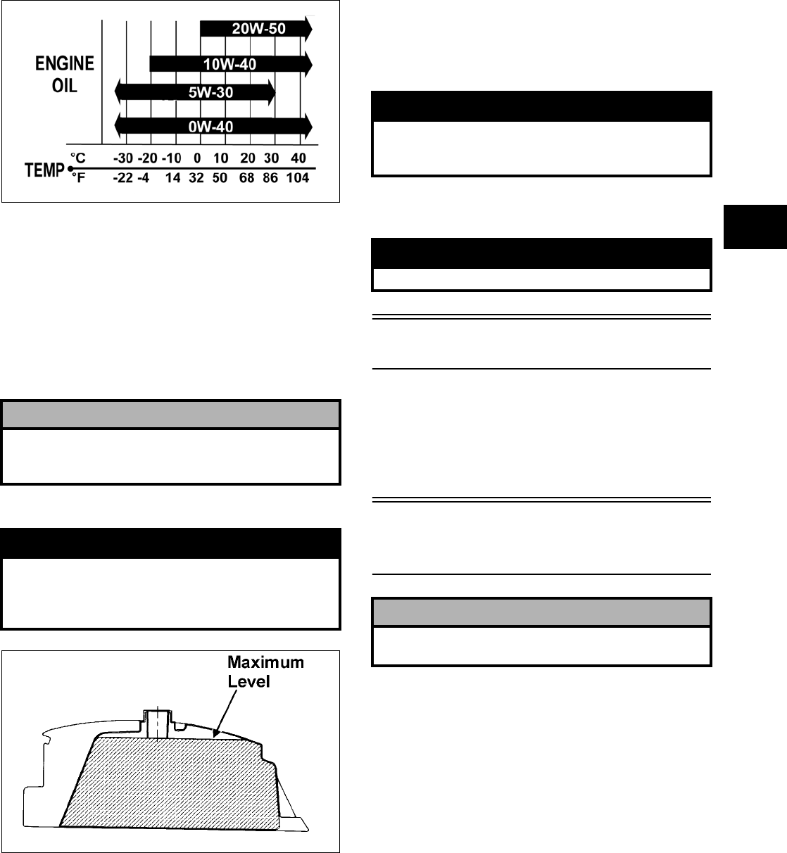
1-9
1
OILCHARTC
RECOMMENDED FRONT
DIFFERENTIAL/REAR DRIVE
LUBRICANT
The recommended lubricant is Arctic Cat Gear Lube
or an equivalent gear lube which is SAE approved
80W-90 hypoid. This lubricant meets all of the
lubrication requirements of the Arctic Cat ATV
front differentials and rear drives.
FILLING GAS TANK
ATV0049B
Since gasoline expands as its temperature rises, the
gas tank must be filled to its rated capacity only.
Expansion room must be maintained in the tank par-
ticularly if the tank is filled with cold gasoline and
then moved to a warm area.
Tighten the gas tank cap securely after filling the
tank.
Genuine Parts
When replacement of parts is necessary, use only
genuine Arctic Cat ATV parts. They are precision-
made to ensure high quality and correct fit. Refer to
the appropriate Illustrated Parts Manual for the cor-
rect part number, quantity, and description.
Preparation
For Storage
Arctic Cat recommends the following procedure to
prepare the ATV for storage.
1. Clean the seat cushion (cover and base) with a
damp cloth and allow it to dry.
2. Clean the ATV thoroughly by washing dirt, oil,
grass, and other foreign matter from the entire
ATV. Allow the ATV to dry thoroughly. DO
NOT get water into any part of the engine or air
intake.
! CAUTION
Any lubricant used in place of the recommended
lubricant could cause serious front differential/rear
drive damage.
! WARNING
Always fill the gas tank in a well-ventilated area.
Never add fuel to the ATV gas tank near any open
flames or with the engine running. DO NOT SMOKE
while filling the gas tank.
! WARNING
Do not overflow gasoline when filling the gas tank. A
fire hazard could materialize. Always allow the
engine to cool before filling the gas tank.
! WARNING
Do not over-fill the gas tank.
! CAUTION
Prior to storing the ATV, it must be properly serviced
to prevent rusting and component deterioration.
FOR ARCTIC CAT ATV DISCOUNT PARTS CALL 606-678-9623 OR 606-561-4983
www.mymowerparts.com

1-10
3. Either drain the gas tank or add Fuel Stabilizer
to the gas in the gas tank. Remove the air filter
housing cover and air filter. Start the engine and
allow it to idle; then using Arctic Cat Engine
Storage Preserver, rapidly inject the preserver
into the air filter opening for a period of 10 to 20
seconds; then stop the engine. Install the air fil-
ter and housing cover.
4. On carbureted models, drain the carburetor float
chamber.
5. Plug the exhaust hole in the exhaust system with
a clean cloth.
6. Apply light oil to the upper steering post bush-
ing and plungers of the shock absorbers.
7. Tighten all nuts, bolts, cap screws, and screws.
Make sure rivets holding components together
are tight. Replace all loose rivets. Care must be
taken that all calibrated nuts, cap screws, and
bolts are tightened to specifications (see Section
10).
8. On liquid cooled models, fill the cooling system
to the bottom of the stand pipe in the radiator
neck with properly mixed coolant.
9. Disconnect the battery cables; then remove the
battery, clean the battery posts and cables, and
store in a clean, dry area.
10. Store the ATV indoors in a level position.
Preparation After
Storage
Taking the ATV out of storage and correctly prepar-
ing it will assure many miles and hours of trouble-
free riding. Arctic Cat recommends the following
procedure to prepare the ATV.
1. Clean the ATV thoroughly.
2. Clean the engine. Remove the cloth from the
exhaust system.
3. Check all control wires and cables for signs of
wear or fraying. Replace if necessary.
4. Change the engine/transmission oil and filter.
5. On liquid cooled models, check the coolant level
and add properly mixed coolant as necessary.
6. Charge the battery; then install. Connect the bat-
tery cables.
7. Check the entire brake systems (fluid level,
pads, etc.), all controls, headlights, taillight,
brakelight, and headlight aim; adjust or replace
as necessary.
8. Tighten all nuts, bolts, cap screws, and screws
making sure all calibrated nuts, cap screws, and
bolts are tightened to specifications (see Section
10).
9. Check tire pressure. Inflate to recommended
pressure as necessary.
10. Make sure the steering moves freely and does
not bind.
11. Check the spark plug. Clean or replace as neces-
sary.
! CAUTION
If the interior of the air filter housing is dirty, clean
the area before starting the engine.
! CAUTION
Avoid storing outside in direct sunlight and avoid
using a plastic cover as moisture will collect on the
ATV causing rusting.
! CAUTION
The ignition switch must be in the OFF position prior
to installing the battery or damage may occur to the
ignition system.
! CAUTION
Connect the positive battery cable first; then the
negative.
FOR ARCTIC CAT ATV DISCOUNT PARTS CALL 606-678-9623 OR 606-561-4983
www.mymowerparts.com

2-1
2
SECTION 2 —
PERIODIC MAINTENANCE/TUNE-UP
TABLE OF
CONTENTS
Periodic Maintenance Chart………………………….….. 2-2
Lubrication Points…………………………….………….….. 2-3
Battery…………………….……………..…………….……….. 2-3
Fuses …………..………………………..…………….……….. 2-4
Air Cleaner/Filter ………………………..…………….…….. 2-4
Valve/Tappet Clearance
(Feeler Gauge Procedure) …………..…………….….. 2-6
Valve/Tappet Clearance
(Valve Adjuster Procedure) ……………….…………… 2-6
Valve/Tappet Clearance (700 EFI)…………….……….. 2-7
Testing Engine Compression………..…………….…….. 2-9
Spark Plug…….…………….………….…………….……… 2-10
Muffler/Spark Arrester …………..…………….…………. 2-10
Gas/Vent Hoses …………………..…………….…………. 2-11
Adjusting Throttle Cable ……..…………….………….… 2-11
Adjusting Engine RPM (Idle) ….…………….…………. 2-11
Engine/Transmission Oil — Filter — Strainer ………… 2-12
Front Differential/Rear Drive Lubricant ……………… 2-14
Adjusting Clutch
(400/500 Manual Transmission) ……………….…… 2-14
Tires …………….………………………..…………….……… 2-15
Steering Components ……………………………….…… 2-15
Driveshaft/Coupling …………………….…………….…… 2-15
Suspension/Shock Absorbers/Bushings …………… 2-16
Nuts/Bolts/Cap Screws……………..…………….……… 2-16
Ignition Timing………….……………..…………….……… 2-16
Headlight/Taillight-Brakelight ………………..…………. 2-16
Switches ………….………….…………….…………….…… 2-17
Shift Lever ……….………….…………….…………….…… 2-18
Frame/Welds/Racks ……………………………….……… 2-19
Electrical Connections…..…………….…………….…… 2-19
Hydraulic Brake Systems ……………….…………….… 2-20
Burnishing Brake Pads….…………….…………….…… 2-21
Coolant (500/650 H1/700 EFI) …………..……………. 2-22
Checking/Replacing V-Belt ………….…………….…… 2-22
Adjusting Differential Lock Cable……..………….…… 2-24
Exhaust Chart .…………….…………….………….……… 2-25
Intake Chart…..…………….…………….………….……… 2-26
FOR ARCTIC CAT ATV DISCOUNT PARTS CALL 606-678-9623 OR 606-561-4983
www.mymowerparts.com

2-2
Periodic Maintenance
Chart
A = Adjust I = Inspect
C = Clean L = Lubricate
D = Drain R = Replace
* Service/Inspect more frequently when operating in adverse conditions.
Item
Initial Service
After Break-In
(First Mo or
100 Mi)
Every
Day
Every
Month or
Every
100 Miles
Every 3
Months
or Every
300 Miles
Every 6
Months
or Every
500 Miles
Every
Year or
Every
1500 Miles
As
Needed
Battery I I C
Fuses IR
Air Filter/Drain Tube I I C* R
Valve/Tappet Clearance I I A
Engine Compression I
Spark Plug I I R (4000 Mi
or 18 Mo)
Muffler/Spark Arrester CR
Gas/Vent Hoses I I R (2 Yrs)
Throttle Cable I I C-L A-R
Carburetor Float Chamber
(Carbureted Models)
D*
Engine Idle RPM
(Carbureted Models)
IIA
Engine-Transmission Oil Level I A
Engine-Transmission Oil/Filter R R* R
Oil Strainer I I C
Front Differential/Rear Drive Lubri-
cant
IR (4 Yrs)
Clutch (Manual) I l A
Tires/Air Pressure I I R
Steering Components I I I R
V-Belt (Automatic) I l R
Suspension (Ball joint boots, drive
axle boots front and rear, tie rods,
differential and rear drive bellows)
Il* R
Nuts/Cap Screws/Screws I I I A
Ignition Timing I
Headlight/Taillight-Brakelight I I R
Switches I I R
Shift Lever IA—L
Recoil Starter
(Except certain 650 H1 models)
IC—R
Handlebar Grips I R
Handlebars I I R
Gauges/Indicators I I R
Frame/Welds/Racks I I l
Electrical Connections lC
Complete Brake System (Hydraulic
& Auxiliary)
II C L—R
Brake Pads I I* R
Brake Fluid I I R (2 Yrs)
Brake Hoses I I R (4 Yrs)
Coolant/Cooling System I I R (2 Yrs)
FOR ARCTIC CAT ATV DISCOUNT PARTS CALL 606-678-9623 OR 606-561-4983
www.mymowerparts.com
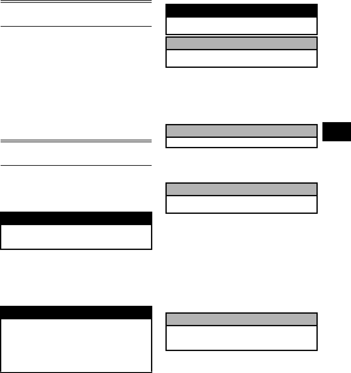
2-3
2
Lubrication Points
It is advisable to lubricate certain components peri-
odically to ensure free movement. Apply light oil to
the components using the following list as reference.
A. Throttle Lever Pivot/Cable Ends
B. Brake Lever Pivot/Cable Ends
C. Auxiliary Brake Cable Ends
D. Shift Lever Cable End
E. Idle RPM Screw (Carburetor) (If Applicable)
Battery
The level of the battery fluid must be kept between
the upper and lower level lines at all times. If the
level drops below the lower level line, add only dis-
tilled water until it reaches upper level line.
If the battery is discharged, remove the battery from
the ATV and charge the battery at 1.5 amps for 10
hours.
To remove and charge the battery, use the following
procedure.
1. Remove the battery hold-down bracket.
2. Remove the negative battery cable; then remove
the positive cable and the battery vent tube.
Remove the battery from the ATV. Care should
be taken not to damage the vent tube.
3. Remove the vent plugs; then (if necessary) fill
the battery with distilled water to the upper
level indicated on the battery.
4. Trickle charge the battery at 1.5 amps for 10
hours.
5. After charging, check fluid level and fill with
distilled water as necessary; then install vent
plugs.
6. Place the battery into position in the ATV and
secure with the hold-down bracket.
7. Attach the vent tube and check the vent tube to
make sure it is not crimped or obstructed in any
way and that it is properly routed through and
secured to the frame.
8. Connect cables to the proper terminals: positive
cable to the positive terminal (+) and negative
cable to the negative terminal (-). Connect the
negative cable last.
! WARNING
Battery acid is harmful if it contacts eyes, skin, or
clothing. Care must be taken whenever handling a
battery.
! WARNING
Anytime service is performed on a battery, the fol-
lowing must be observed: keep sparks, open flame,
cigarettes, or any other flame away. Always wear
safety glasses. Protect skin and clothing when han-
dling a battery. When servicing battery in enclosed
space, keep the area well-ventilated. Make sure bat-
tery venting is not obstructed.
! WARNING
Avoid spillage and contact with skin, eyes, and
clothing.
! CAUTION
Do not charge the battery while it is in the ATV with
the battery terminals connected.
! CAUTION
Never exceed the standard charging rate.
! CAUTION
Before installing the battery, make sure the ignition
switch is in the OFF position.
! CAUTION
Connecting cables in reverse (positive to negative
and negative to positive) can cause serious damage
to the electrical system.
FOR ARCTIC CAT ATV DISCOUNT PARTS CALL 606-678-9623 OR 606-561-4983
www.mymowerparts.com
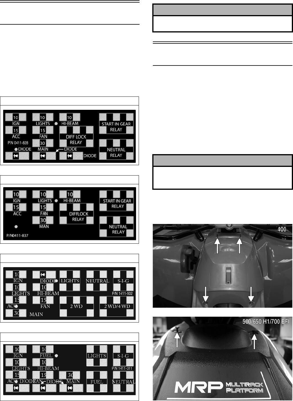
2-4
Fuses
The fuses are located in a power distribution module
under the seat.
If there is any type of electrical system failure,
always check the fuses first.
NOTE: To remove a fuse, compress the locking
tabs on either side of the fuse case and lift out.
0411-828
0411-837
1411-502
1411-311
Air Cleaner/Filter
The air filter inside the air filter housing must be
kept clean to provide good engine power and gas
mileage. If the ATV is used under normal condi-
tions, service the filter at the intervals specified. If
operated in dusty, wet, or muddy conditions, inspect
and service the filter more frequently. Use the fol-
lowing procedure to remove the filter and inspect
and/or clean it.
CLEANING AND INSPECTING
FILTER
1. Remove the seat; then remove the appropriate
reinstallable rivets securing the storage compart-
ment.
CF145C
CD710C
400/400 TRV/500 Auto
400/500 Manual
650 H1/650 H1 TBX/650 H1 TRV
700 EFI
! CAUTION
Always replace a blown fuse with a fuse of the same
type and rating.
! CAUTION
Failure to inspect the air filter frequently if the vehi-
cle is used in dusty, wet, or muddy conditions can
damage the engine.
FOR ARCTIC CAT ATV DISCOUNT PARTS CALL 606-678-9623 OR 606-561-4983
www.mymowerparts.com
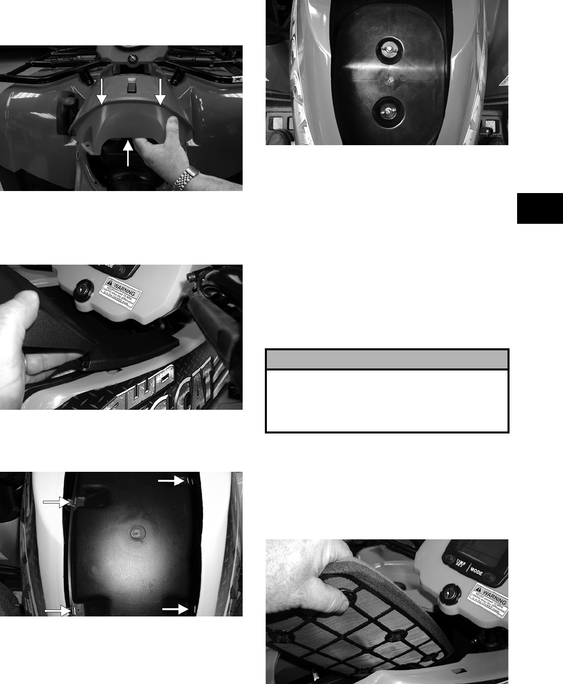
2-5
2
2. On the 400, remove the storage compartment
assembly by elevating the rear of the compart-
ment, moving it rearward, and lifting it off.
CF143A
3. On the 500/650 H1/700 EFI, raise the storage
compartment cover; then slide the cover forward
and off the compartment. Remove the storage
compartment.
CD669
4. Unsnap the four spring-clip fasteners
(400/500/650 H1) or remove two wing-nuts
(700 EFI); then remove the air filter cover.
CD675A
FI033
5. Remove the air filter/filter screen assembly and
separate the foam filter from the screen.
6. Fill a wash pan larger than the filter with a
non-flammable cleaning solvent; then dip the
filter in the solvent and wash it.
NOTE: Foam Air Filter Cleaner and Foam Air Fil-
ter Oil are available from Arctic Cat.
7. Dry the filter.
8. Put the filter in a plastic bag; then pour in air fil-
ter oil and work the filter. Reattach the filter to
the filter screen.
9. Clean any dirt or debris from inside the air
cleaner. Be sure no dirt enters the carburetor (if
equipped).
10. Place the filter assembly in the air filter housing
making sure it is properly positioned and prop-
erly seated with the filter screen down.
CD674
! CAUTION
A torn air filter can cause damage to the ATV engine.
Dirt and dust may get inside the engine if the ele-
ment is torn. Carefully examine the element for tears
before and after cleaning it. Replace the element
with a new one if it is torn.
FOR ARCTIC CAT ATV DISCOUNT PARTS CALL 606-678-9623 OR 606-561-4983
www.mymowerparts.com
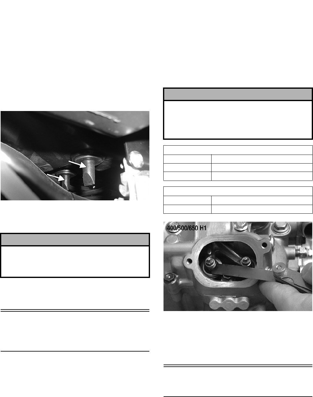
2-6
11. Install the air filter housing cover and secure
with the retaining clips (400/500/650 H1) or
wing-nuts (700 EFI).
12. Install the storage compartment; then secure
with the reinstallable rivets.
CHECKING AND CLEANING
DRAINS
1. Inspect one-way drains beneath the main hous-
ing for debris and for proper sealing.
KX045A
2. Replace any one-way drain that is cracked or
shows any signs of hardening or deterioration.
3. Wipe any accumulation of oil or gas from the
filter housing and one-way drains.
Valve/Tappet
Clearance
(Feeler Gauge Procedure)
NOTE: For the 700 EFI, see Valve/Tappet Clear-
ance (700 EFI) in this section.
To check and adjust valve/tappet clearance, use the
following procedure.
1. Remove the timing inspection plug; then
remove the tappet covers (for more detailed
information, see Section 3 — Servicing Top-Side
Components).
2. Rotate the crankshaft to the TDC position on the
compression stroke.
NOTE: At this point, the rocker arms and
adjuster screws must not have pressure on them.
3. Using a feeler gauge, check each valve/tappet
clearance. If clearance is not within specifica-
tions, loosen the jam nut and rotate the tappet
adjuster screw until the clearance is within spec-
ifications. Tighten each jam nut securely after
completing the adjustment.
CC007DB
4. Install the timing inspection plug.
5. Place the two tappet covers into position making
sure the proper cap screws are with the proper
cover. Tighten the cap screws securely.
Valve/Tappet Clearance
(Valve Adjuster Procedure)
NOTE: For the 700 EFI, see Valve/Tappet Clear-
ance (700 EFI) in this section.
To check and adjust valve/tappet clearance, use the
following procedure.
! CAUTION
The one-way drain to the right is the clean air sec-
tion of the filter housing. Any leak of this one-way
drain will allow dirt into the engine intake causing
severe engine damage.
! CAUTION
The feeler gauge must be positioned at the same
angle as the valve and valve adjuster for an accurate
measurement of clearance. Failure to measure the
valve clearance accurately could cause valve com-
ponent damage.
VALVE/TAPPET CLEARANCE (400/500)
Intake 0.05-0.10 mm (0.002-0.004 in.)
Exhaust (400) 0.22-0.27 mm (0.009-0.011 in.)
Exhaust (500) 0.17-0.22 mm (0.007-0.009 in.)
VALVE/TAPPET CLEARANCE (650 H1)
Intake 0.1016 mm (0.004 in.)
Exhaust 0.1524 mm (0.006 in.)
FOR ARCTIC CAT ATV DISCOUNT PARTS CALL 606-678-9623 OR 606-561-4983
www.mymowerparts.com
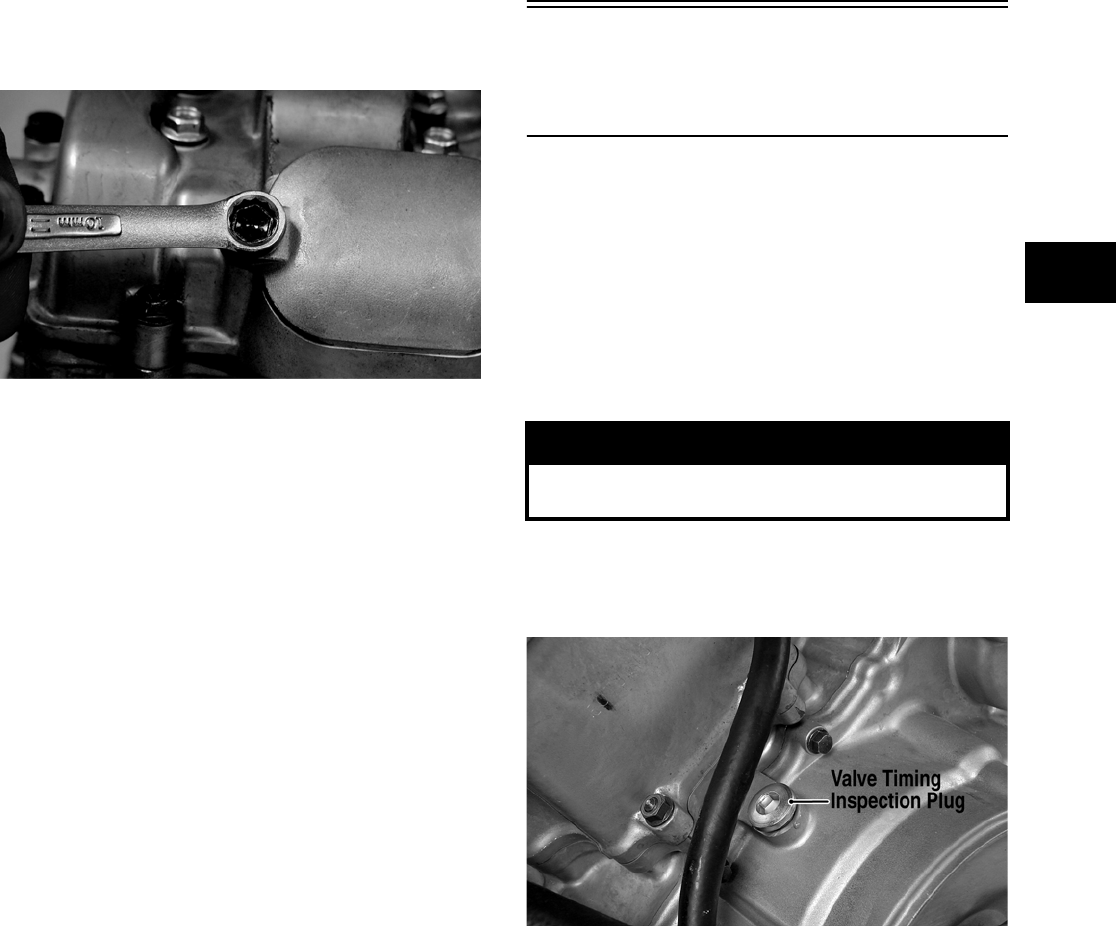
2-7
2
NOTE: On the TBX/500/650 H1, the seat, storage
compartment cover assembly, compartment box,
air filter/filter housing, and left-side/right-side
splash panels must be removed for this procedure.
1. Remove the timing inspection plug; then
remove the tappet covers (for more detailed
information, see Section 3 — Servicing Top-Side
Components).
CF005
2. Rotate the crankshaft to the TDC position on the
compression stroke.
NOTE: At this point, the rocker arms and
adjuster screws must not have pressure on them.
NOTE: Use Valve Clearance Adjuster (p/n
0444-078) for this procedure.
3. Place the valve adjuster onto the jam nut secur-
ing the tappet adjuster screw; then rotate the
valve adjuster dial clockwise until the end is
seated in the tappet adjuster screw.
4. While holding the valve adjuster dial in place,
use the valve adjuster handle and loosen the jam
nut; then rotate the tappet adjuster screw clock-
wise until friction is felt.
5. Align the valve adjuster handle with one of the
marks on the valve adjuster dial.
6. While holding the valve adjuster handle in
place, rotate the valve adjuster dial counter-
clockwise until proper valve/tappet clearance is
attained.
NOTE: Refer to the appropriate specifications in
Feeler Gauge Procedure sub-section for the proper
valve/tappet clearance.
NOTE: Rotating the valve adjuster dial counter-
clockwise will open the valve/tappet clearance by
0.05 mm (0.002 in.) per mark.
7. While holding the adjuster dial at the proper
clearance setting, tighten the jam nut securely
with the valve adjuster handle.
8. Place the two tappet covers with O-rings into
position; then tighten the covers securely.
9. Install the spark plug; then install the timing
inspection plug.
Valve/Tappet
Clearance
(700 EFI)
To check and adjust valve/tappet clearance, use the
following procedure.
NOTE: The seat, heat shields, splash panels,
front rack, and front fenders must be removed for
this procedure (see Section 8).
1. Remove the spark plug cap/high tension lead;
then using compressed air, blow any debris from
around the spark plug.
2. Remove the recoil starter assembly; then
remove the valve timing inspection plug and the
cylinder head cover.
FI039A
3. Using an appropriate bar, rotate the engine
through two full revolutions; then while on the
compression stroke, align the TDC line on the
starter clutch with the index mark on the crank-
case.
! WARNING
Always wear safety glasses when using compressed
air.
FOR ARCTIC CAT ATV DISCOUNT PARTS CALL 606-678-9623 OR 606-561-4983
www.mymowerparts.com
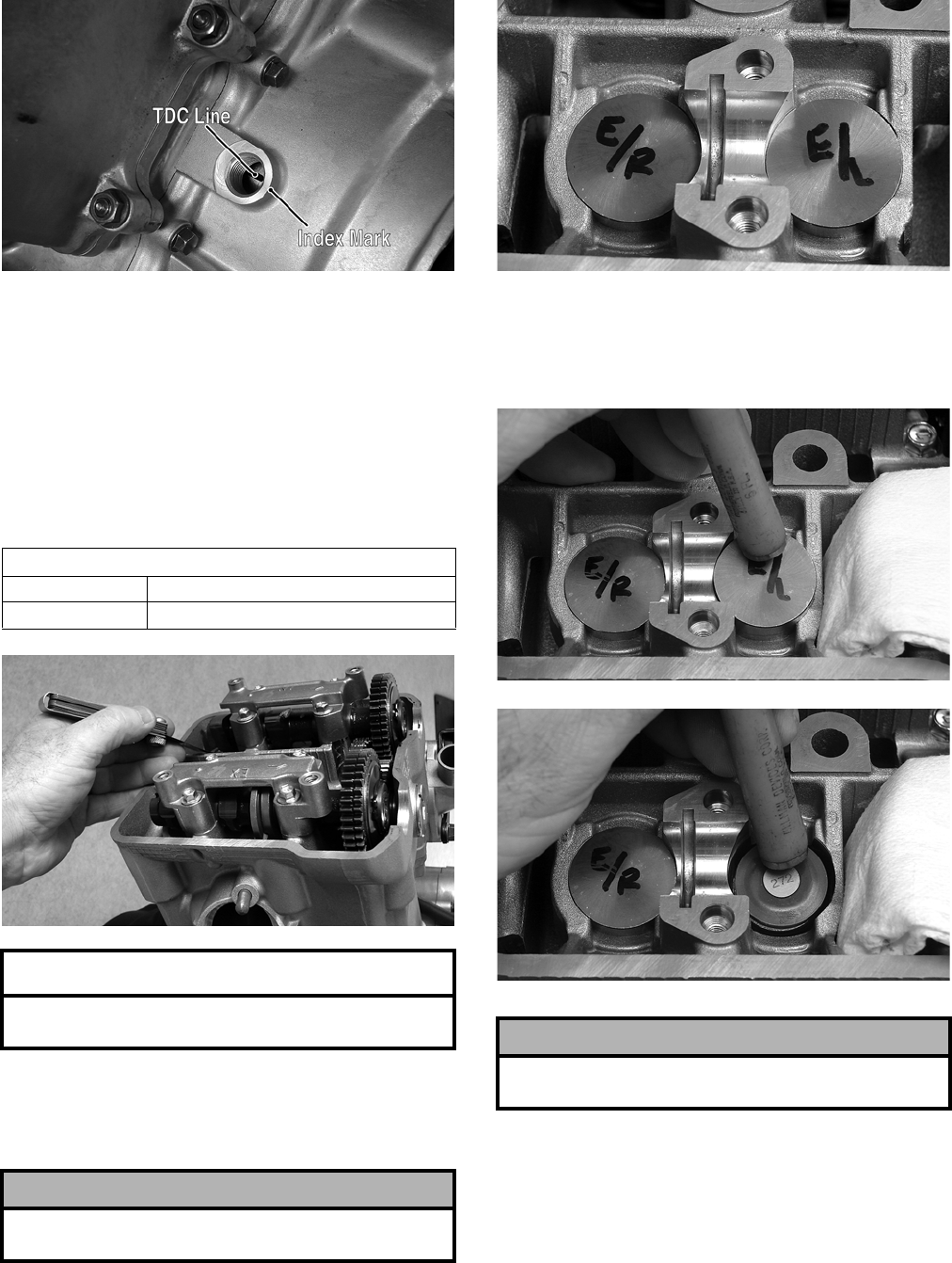
2-8
FI041A
NOTE: Rotating the engine ensures that any
trapped oil is squeezed from the tappets and tap-
pet shims. Oil trapped in these areas could result
in a false valve clearance reading.
4. Using an appropriate thickness gauge, measure
and record the clearance of both intake valves;
then measure and record the clearance of both
exhaust valves. Valve clearance must be within
specifications.
FI046
5. Identify the valves that are not within specifica-
tions; then remove the corresponding camshaft
(see Section 3 — Removing Top-Side Compo-
nents).
6. Mark the valve tappets in order to return them to
the proper position during assembly.
FI054
7. Fold a suitable towel and use it to plug the cam-
shaft drive passageway; then using a magnet,
remove the tappet and shim from the appropriate
valve.
FI055
FI056
8. Note the three digit number on the surface of the
tappet shim; then refer to the appropriate tappet
shim selection table at the end of this section for
the correct replacement.
VALVE/TAPPET CLEARANCE (700 EFI)
Intake 0.10-0.20 mm (0.004-0.008 in.)
Exhaust 0.20-0.30 mm (0.008-0.012 in.)
AT THIS POINT
If valve clearance is within specifications, proceed
to step 12.
! CAUTION
When removing camshaft holders, use extreme care
not to drop alignment pins into the engine.
! CAUTION
If the camshaft passageway is not plugged, tappet
shims could fall into the engine crankcase.
FOR ARCTIC CAT ATV DISCOUNT PARTS CALL 606-678-9623 OR 606-561-4983
www.mymowerparts.com
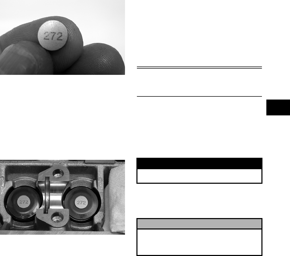
2-9
2
FI051
A. Measured tappet clearance from step 4 in ver-
tical column on left.
B. Present shim size horizontal row at the top.
C. Match measured clearance in vertical column
with current shim size in horizontal row to
find recommended replacement size.
9. Apply engine oil to both surfaces of the tappet
shim; then place the shim on the valve with the
numbers toward the tappet.
FI053
10. Install the tappet on the appropriate valve; then
install the camshaft.
11. Using an appropriate bar, rotate the engine
through two full revolutions; then rotate to TDC
on the compression stroke and check the valve
tappet clearance.
NOTE: Rotating the engine ensures that any
excess oil is squeezed from the tappets and tappet
shims. Oil trapped in these areas could result in a
false valve clearance reading.
12. Using a new gasket, apply Three Bond Sealant
to the camshaft end caps of the cylinder head
cover gasket; then install the cylinder head
cover and tighten the four cap screws to specifi-
cations (see Section 10).
13. Install the valve timing inspection plug and
tighten securely; then install the recoil starter
assembly and secure with the four cap screws
coated with blue Loctite #242. Tighten to speci-
fications (see Section 10).
14. Install the spark plug cap/high tension lead,
front fenders, front rack, and splash panels; then
install the heat shields and seat making sure the
seat locks securely.
Testing Engine
Compression
To test engine compression, use the following pro—
cedure.
1. Remove the high tension lead from the spark
plug.
2. Using compressed air, blow any debris from
around the spark plug.
3. Remove the spark plug; then attach the high ten-
sion lead to the plug and ground the plug on the
cylinder head well away from the spark plug
hole.
4. Attach the Compression Tester Kit (p/n
0444-213).
NOTE: The engine must be warm and the bat-
tery must be fully charged for this test.
5. While holding the throttle lever in the full-open
position, crank the engine over with the electric
starter until the gauge shows a peak reading
(five to 10 compression strokes).
NOTE: For the 400, the compression should be
within a range of 95-115 psi in the full-open throttle
position. For the 500/650 H1, the compression
should be within a range of 70-85 psi in the
full-open throttle position. For the 700 EFI, the
compression should be within a range of 130-155
psi in the full-open throttle position.
! WARNING
Always wear safety glasses when using compressed
air.
! CAUTION
On the 700 EFI, do not ground the spark plug on the
cylinder head cover. The cover is made of magne-
sium and any contact with spark or electrical arc will
severely pit the surface.
FOR ARCTIC CAT ATV DISCOUNT PARTS CALL 606-678-9623 OR 606-561-4983
www.mymowerparts.com
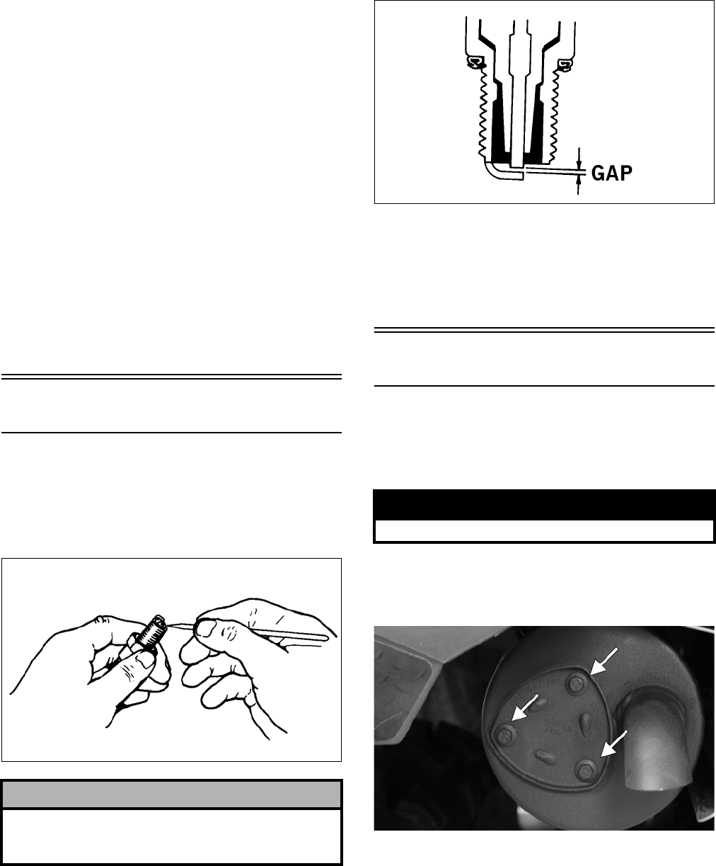
2-10
6. If compression is abnormally low, inspect the
following items.
A. Verify starter cranks engine over at normal
speed (approximately 400 RPM).
B. Gauge functioning properly.
C. Throttle lever in the full-open position.
D. Valve/tappet clearance correct.
E. Valve not bent or burned.
F. Valve seat not burned.
NOTE: To service valves, see Section 3.
7. Pour 29.5 ml (1 fl oz) of oil into the spark plug
hole, reattach the gauge, and retest compression.
8. If compression is now evident, service the piston
rings (see Section 3).
Spark Plug
A light brown insulator indicates that a plug is cor-
rect. A white or dark insulator indicates that the
engine may need to be serviced or the carburetor (if
equipped) may need to be adjusted. To maintain a
hot, strong spark, keep the plug free of carbon.
ATV-0051
Adjust the gap to 0.7-0.8 mm (0.028-0.032 in.) for
proper ignition. Use a feeler gauge to check the gap.
ATV0052B
When installing the spark plug, be sure to tighten it
securely. A new spark plug should be tightened 1/2
turn once the washer contacts the cylinder head. A
used spark plug should be tightened 1/8 — 1/4 turn
once the washer contacts the cylinder head.
Muffler/Spark Arrester
The muffler has a spark arrester which must be peri-
odically cleaned. At the intervals shown in the Peri-
odic Maintenance Chart, clean the spark arrester
using the following procedure.
1. Remove the three cap screws securing the spark
arrester assembly to the muffler; then loosen and
remove the arrester.
CF105A
2. Using a suitable brush, clean the carbon deposits
from the screen taking care not to damage the
screen.
NOTE: If the screen or gasket is damaged in any
way, it must be replaced.
3. Install the spark arrester assembly with gasket;
then secure with the three cap screws. Tighten to
0.6 kg-m (4.0 ft-lb).
! CAUTION
Before removing a spark plug, be sure to clean the
area around the spark plug. Dirt could enter engine
when removing or installing the spark plug.
! WARNING
Wait until the muffler cools to avoid burns.
FOR ARCTIC CAT ATV DISCOUNT PARTS CALL 606-678-9623 OR 606-561-4983
www.mymowerparts.com
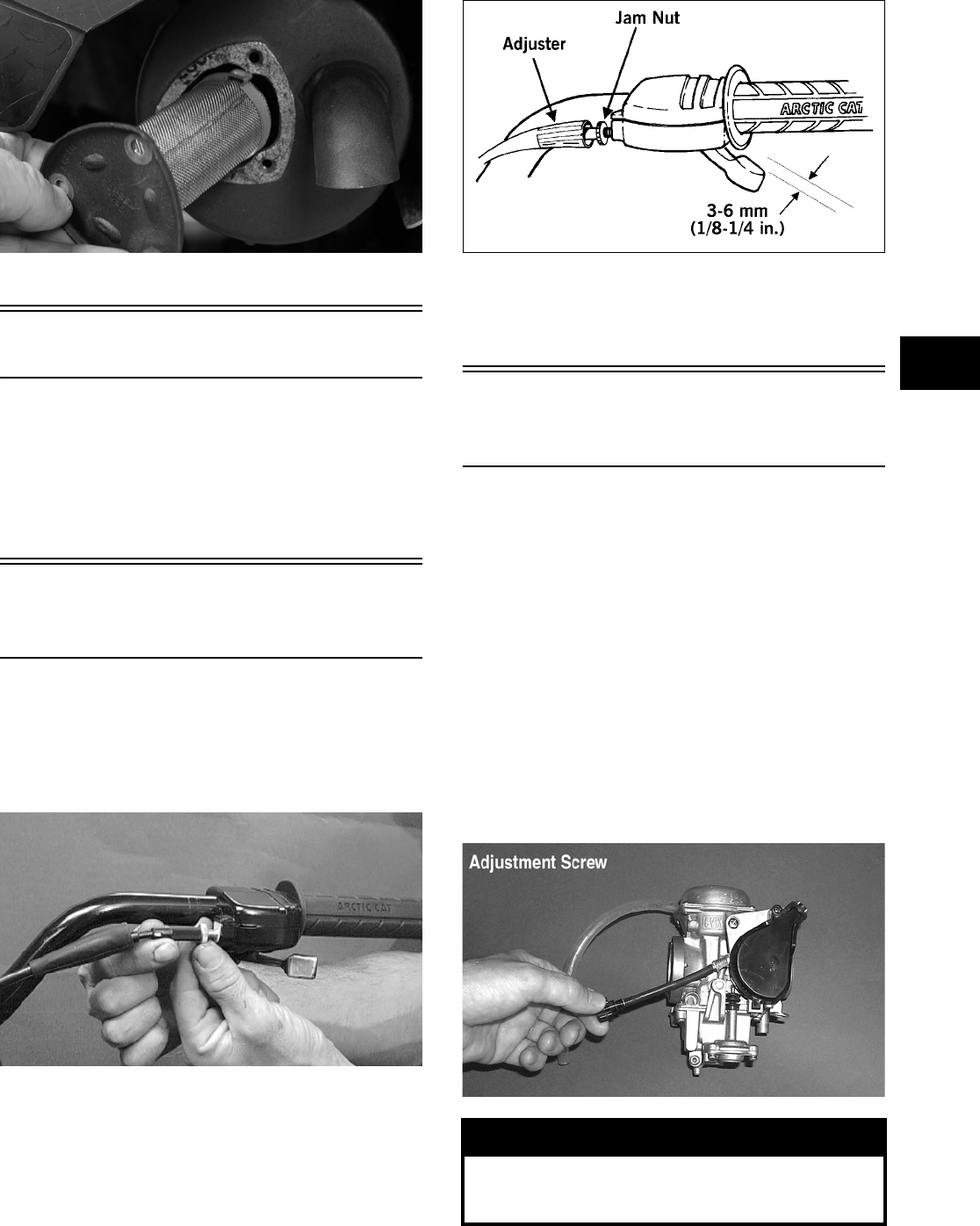
2-11
2
CF104
Gas/Vent Hoses
Replace the gas hose every two years. Damage from
aging may not always be visible. Do not bend or
obstruct the routing of the carburetor/throttle body
vent hose. Make certain that the vent hose is
securely connected to the carburetor/throttle body
and the opposite end is always open.
Adjusting Throttle
Cable
To adjust the throttle cable free-play, follow this
procedure.
1. Slide the rubber boot away; then loosen the jam
nut from the throttle cable adjuster.
AL611D
2. Turn the adjuster until the throttle cable has
proper free-play of 3-6 mm (1/8-1/4 in.) at the
lever.
ATV-0047
3. Tighten the jam nut against the throttle cable
adjuster securely; then slide the rubber boot over
the adjuster.
Adjusting Engine RPM
(Idle)
NOTE: The idle RPM is not adjustable on the
700 EFI.
To properly adjust the idle RPM, a tachometer is
necessary. To adjust idle RPM, use the following
procedure.
NOTE: The idle adjustment screw is located on
the right-hand side of the carburetor.
1. With the transmission in neutral, start the engine
and warm it up to normal operating temperature.
2. Turn the idle adjustment screw clockwise one
turn past the recommended RPM setting; then
turn it counterclockwise to 1250-1350 RPM.
AF920D
! WARNING
Adjust the idle to the correct RPM. Make sure the
engine is at normal operating temperature before
adjusting the idle RPM.
FOR ARCTIC CAT ATV DISCOUNT PARTS CALL 606-678-9623 OR 606-561-4983
www.mymowerparts.com
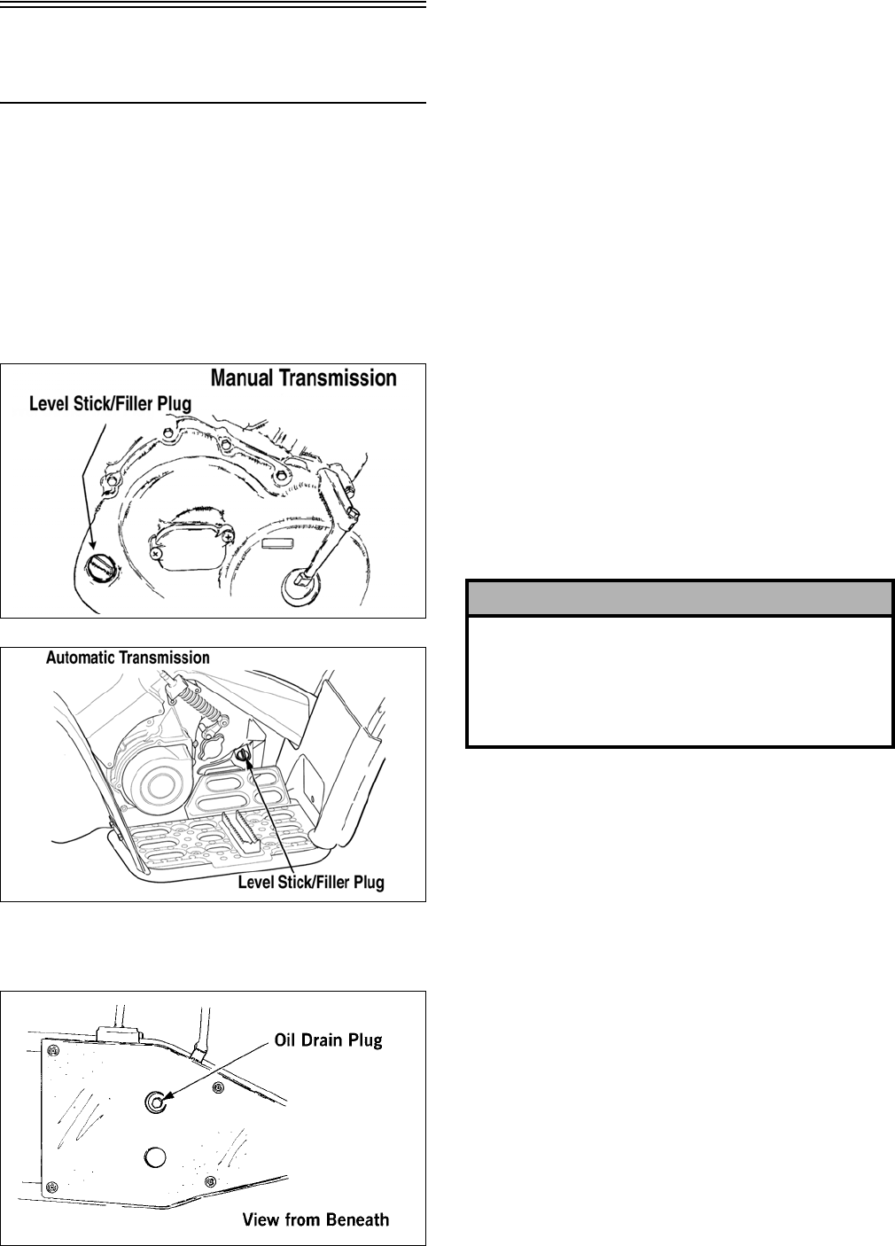
2-12
Engine/Transmission
Oil — Filter — Strainer
OIL — FILTER
Change the engine oil and oil filter at the scheduled
intervals. The engine should always be warm when
the oil is changed so the oil will drain easily and
completely.
1. Park the ATV on level ground.
2. Remove the oil level stick/filler plug.
ATV-0075
0735-505
3. Remove the drain plug from the bottom of the
engine and drain the oil into a drain pan.
733-441A
4. On the 400/500, remove the oil filter plug from
the filter mounting boss (located on the front
side of the transmission case) and allow the fil-
ter to drain completely. Install the plug and
tighten securely.
5. On the 700 EFI, remove the left-side engine
cover and the left-front inner fender panel.
6. Using the adjustable Oil Filter Wrench (p/n
0644-389) and a suitable wrench, remove the
old oil filter.
NOTE: Clean up any excess oil after removing
the filter.
7. Apply oil to a new filter O-ring and check to
make sure it is positioned correctly; then install
the new oil filter. Tighten securely.
NOTE: Install a new O-ring each time the filter is
replaced.
8. Install the engine drain plug and tighten to spec-
ifications. Pour the specified amount of the rec-
ommended oil in the filler hole. Install the oil
level stick/filler plug.
9. Start the engine (while the ATV is outside on
level ground) and allow it to idle for a few min-
utes.
10. Turn the engine off and wait approximately one
minute.
11. Unscrew the oil level stick and wipe it with a
clean cloth.
12. Install the oil level stick until the threads touch
engine case.
NOTE: The oil level stick should not be threaded
into the case for checking the oil level.
13. Remove the oil level stick; the engine oil level
should be above the illustrated “L” mark but not
higher than the illustrated “F” mark.
! CAUTION
Any oil used in place of the recommended oil could
cause serious engine damage. Do not use oils which
contain graphite or molybdenum additives. These
oils can adversely affect clutch operation. Also, not
recommended are racing, vegetable, non-detergent,
and castor-based oils.
FOR ARCTIC CAT ATV DISCOUNT PARTS CALL 606-678-9623 OR 606-561-4983
www.mymowerparts.com
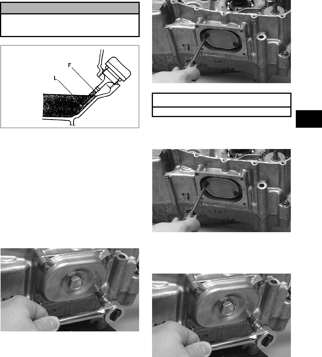
2-13
2
ATV-0100
14. Inspect the area around the drain plug and oil fil-
ter for leaks.
15. On the 700 EFI, install the left-side engine cover
and the left-front inner fender panel.
STRAINER
To check the oil strainer, use the following proce-
dure.
1. Remove the belly panel.
2. Remove the cap screws securing the oil strainer
cap; then remove the cap. Account for the
O-ring.
CC091D
3. Remove the two Phillips-head cap screws secur-
ing the strainer.
CC163D
4. Place the oil strainer into position beneath the
crankcase and secure with the Phillips-head cap
screws. Tighten securely.
CC163D
5. Place the strainer cap into position on the
strainer making sure the O-ring is properly
installed; then secure with the cap screws.
Tighten securely.
CC091D
6. Install the belly panel.
! CAUTION
Do not over-fill the engine with oil. Always make
sure that the oil level is above the “L” mark but not
higher than the “F” mark.
AT THIS POINT
To service oil strainer, see Section 3.
FOR ARCTIC CAT ATV DISCOUNT PARTS CALL 606-678-9623 OR 606-561-4983
www.mymowerparts.com
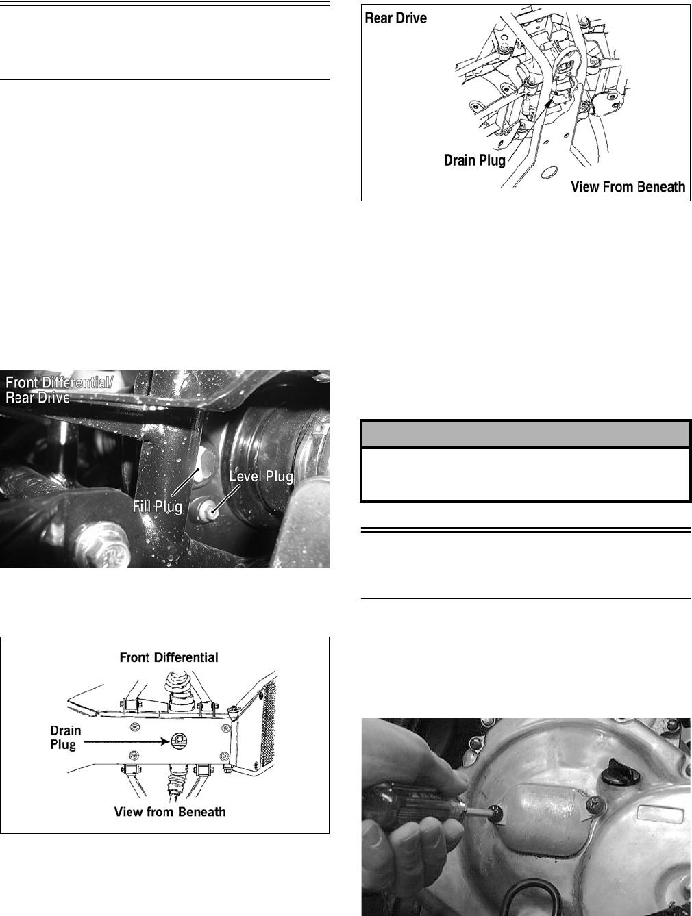
2-14
Front Differential/Rear
Drive Lubricant
Check and change the lubricant according to the
Periodic Maintenance Chart. When changing the
lubricant, use approved SAE 80W-90 hypoid gear
lube.
To check lubricant, remove the rear drive filler plug;
the lubricant level should be 1 in. below the threads
of the plug. If low, add SAE approved 80W-90
hypoid gear lube as necessary.
To change the lubricant, use the following proce-
dure.
1. Place the ATV on level ground.
2. Remove each oil fill plug.
AL677C
3. Drain the oil into a drain pan by removing in
turn the drain plug from each.
ATV0082A
737-651B
4. After all the oil has been drained, install the
drain plugs and tighten to specifications (see
Section 10).
5. Pour the appropriate amount of recommended
oil into the filler hole.
6. Install the fill plugs.
NOTE: If the differential/rear drive oil is contam-
inated with water, inspect the drain plug, filler
plug, and/or bladder.
Adjusting Clutch
(400/500 Manual Transmission)
To adjust the clutch, use the following procedure.
1. Using an impact driver, remove the screws
securing the cover and remove the cover.
Account for the O-ring.
AM600D
2. Loosen the jam nuts securing adjustment screw
#1 (forward) and adjustment screw #2 (rear-
ward).
! CAUTION
Water entering the outer end of the axle will not be
able to enter the rear drive unless the seals are dam-
aged.
FOR ARCTIC CAT ATV DISCOUNT PARTS CALL 606-678-9623 OR 606-561-4983
www.mymowerparts.com
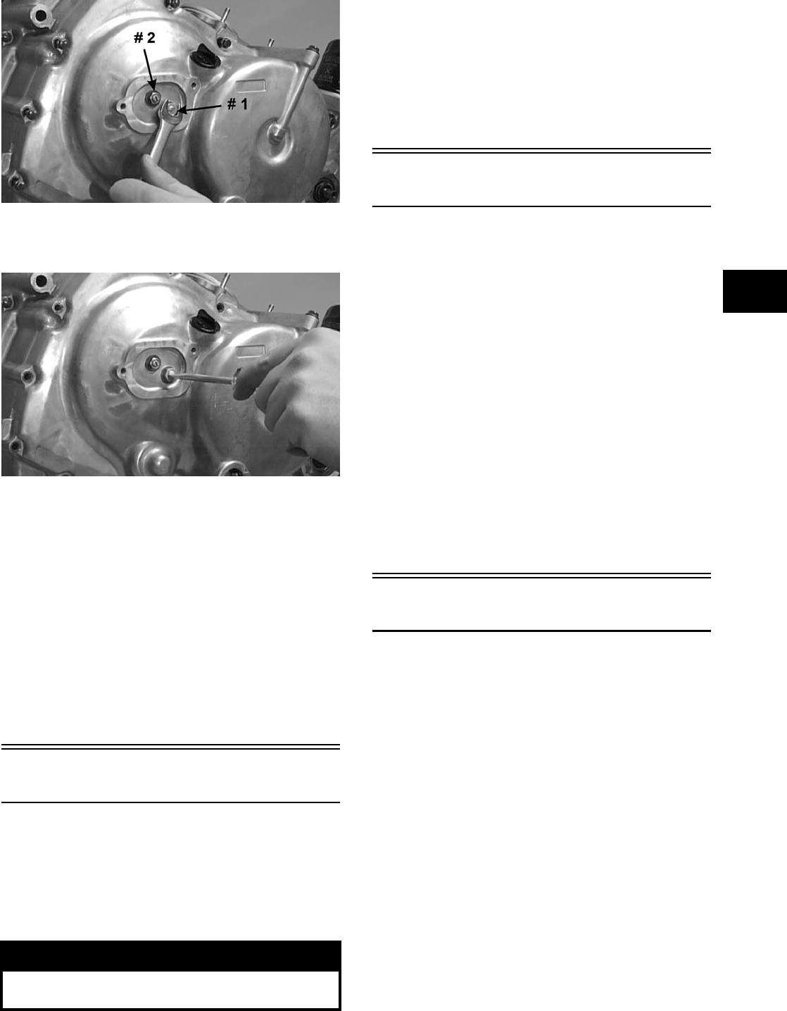
2-15
2
CC037D
3. Rotate adjustment screw #1 counterclockwise
until it stops.
CC038D
4. Rotate adjustment screw #2 alternately clock-
wise and counterclockwise to ensure free move-
ment without binding; then lock the jam nut
securing adjustment screw #2.
5. Rotate adjustment screw #1 clockwise 1/8 turn;
then lock the jam nut securing adjustment screw
#1.
NOTE: At this point the clutch should be adjusted
correctly. Test to ensure accurate adjustment.
6. Install the cover making sure the O-ring is prop-
erly positioned; then secure with the screws.
Tires
TIRE SIZES
The ATV is equipped with low-pressure tubeless
tires of the size and type listed (see Section 1). Do
not under any circumstances substitute tires of a dif-
ferent type or size.
TIRE INFLATION PRESSURE
Front and rear tire inflation pressure should be 0.35
kg-cm² (5.0 psi).
A low-pressure gauge is provided in the tool kit to
measure the air pressure in the tires. Check the air
pressure in all tires before each use of the ATV.
Steering Components
The following steering components should be
inspected periodically to ensure safe and proper
operation.
A. Handlebar grips not worn, broken, or loose.
B. Handlebar not bent, cracked, and has equal
and complete full-left and full-right capabil-
ity.
C. Steering post bearing assembly/bearing hous-
ing not broken, worn, or binding.
D. Ball joints not worn, cracked, or damaged.
E. Tie rods not bent or cracked.
F. Knuckles not worn, cracked, or damaged.
G. Cotter pins not damaged or missing.
Driveshaft/Coupling
The following drive system components should be
inspected periodically to ensure proper operation.
A. Spline lateral movement (slop).
B. Coupling cracked, damaged, or worn.
! WARNING
Always use the size and type of tires specified.
Always maintain proper tire inflation pressure.
FOR ARCTIC CAT ATV DISCOUNT PARTS CALL 606-678-9623 OR 606-561-4983
www.mymowerparts.com

2-16
Suspension/Shock
Absorbers/Bushings
The following suspension system components
should be inspected periodically to ensure proper
operation.
A. Shock absorber rods not bent, pitted, or dam-
aged.
B. Rubber damper not cracked, broken, or miss-
ing.
C. Shock absorber body not damaged, punc-
tured, or leaking.
D. Shock absorber eyelets not broken, bent, or
cracked.
E. Shock absorber eyelet bushings not worn,
deteriorated, cracked, or missing.
F. Shock absorber spring not broken or sagging.
Nuts/Bolts/Cap Screws
Tighten all nuts, bolts, and cap screws. Make sure
rivets holding components together are tight.
Replace all loose rivets. Care must be taken that all
calibrated nuts, bolts, and cap screws are tightened
to specifications (see Section 10).
Ignition Timing
NOTE: The 700 EFI rotor/flywheel does not have
timing marks; therefore, timing cannot be verified.
The ignition timing cannot be adjusted; however,
verifying ignition timing can aid in troubleshooting
other components. To verify ignition timing, use the
following procedure.
1. Attach the Timing Light (p/n 0644-296) to the
spark plug high tension lead; then remove the
timing inspection plug from the left-side crank-
case cover.
2. Using the Tachometer (p/n 0644-275), start the
engine and run at 1500 RPM; ignition timing
should be 10° BTDC.
3. Install the timing inspection plug.
If ignition timing cannot be verified, the rotor may
be damaged, the key may be sheared, the trigger
coil/CKP sensor bracket may be bent or damaged, or
the CDI unit/ECU may be faulty.
Headlight/Taillight-
Brakelight
Each time the ATV is used, lights should be checked
for proper function. Rotate the ignition switch to the
lights position; the headlights and taillight should
illuminate. Test the brakelight by compressing the
brake lever. The brakelight should illuminate.
HEADLIGHT
NOTE: The bulb portion of the headlight is frag-
ile. HANDLE WITH CARE. When replacing the
headlight bulb, do not touch the glass portion of
the bulb. If the glass is touched, it must be cleaned
with a dry cloth before installing. Skin oil residue
on the bulb will shorten the life of the bulb.
To replace the headlight bulb, use the following pro-
cedure.
1. Remove the wiring harness connector from the
back of the headlight.
2. Grasp the bulb housing, turn it counterclock-
wise, and remove the bulb.
3. Install the new bulb into the housing and rotate
it completely clockwise.
4. Install the wiring harness connector.
TAILLIGHT-BRAKELIGHT
To replace the taillight-brakelight bulb, use the fol-
lowing procedure.
1. Turn the bulb socket assembly counterclockwise
and remove from the housing.
! WARNING
Do not attempt to remove the bulb when it is hot.
Severe burns may result.
FOR ARCTIC CAT ATV DISCOUNT PARTS CALL 606-678-9623 OR 606-561-4983
www.mymowerparts.com
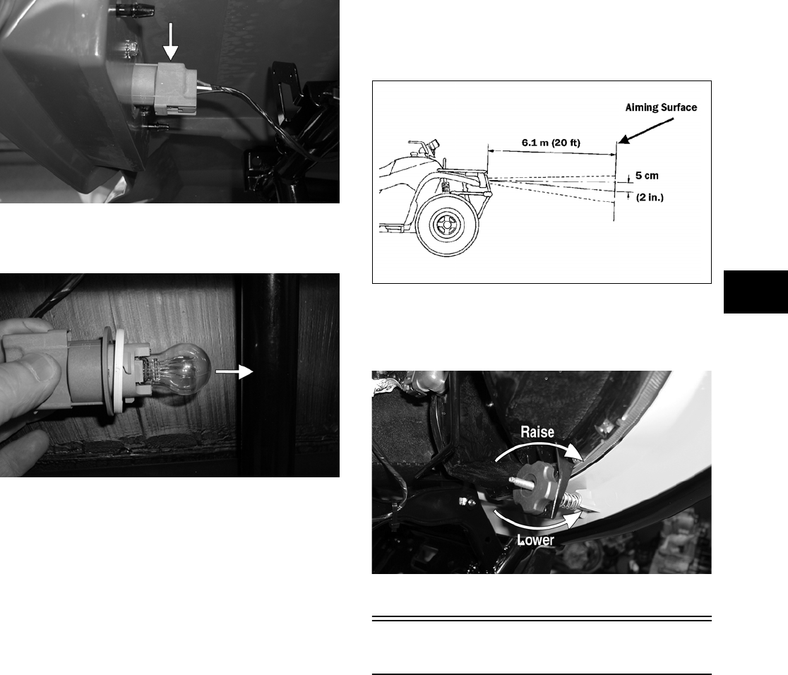
2-17
2
CF135A
2. Pull the bulb straight out of the socket; then
insert a new bulb.
CF132A
3. Insert the bulb socket assembly into the housing
and turn it clockwise to secure.
CHECKING/ADJUSTING
HEADLIGHT AIM
The headlights can be adjusted vertically and hori-
zontally. The geometric center of the HIGH beam
light zone is to be used for vertical and horizontal
aiming.
1. Position the ATV on a level floor so the head-
lights are approximately 6.1 m (20 ft) from an
aiming surface (wall or similar aiming surface).
NOTE: There should be an average operating
load on the ATV when adjusting the headlight aim.
2. Measure the distance from the floor to the
mid-point of each headlight.
3. Using the measurements obtained in step 2,
make horizontal marks on the aiming surface.
4. Make vertical marks which intersect the hori-
zontal marks on the aiming surface directly in
front of the headlights.
5. Switch on the lights. Make sure the HIGH beam
is on. DO NOT USE LOW BEAM.
6. Observe each headlight beam aim. Proper aim is
when the most intense beam is centered on the
vertical mark 5 cm (2 in.) below the horizontal
mark on the aiming surface.
ATV-0070C
7. Adjust each headlight by turning the adjuster
knob clockwise to raise the beam or counter-
clockwise to lower the beam.
CD714A
Switches
Each time the ATV is used, switches should be
checked for proper operation. Use the following list
for reference.
A. Ignition switch — engine will start.
B. Emergency stop switch — engine will stop.
C. Reverse switch — reverse indicator light will
illuminate.
D. Hi/Lo switch — headlight beam bright and
dim.
E. Brake switches — rear brakelight will illumi-
nate.
FOR ARCTIC CAT ATV DISCOUNT PARTS CALL 606-678-9623 OR 606-561-4983
www.mymowerparts.com
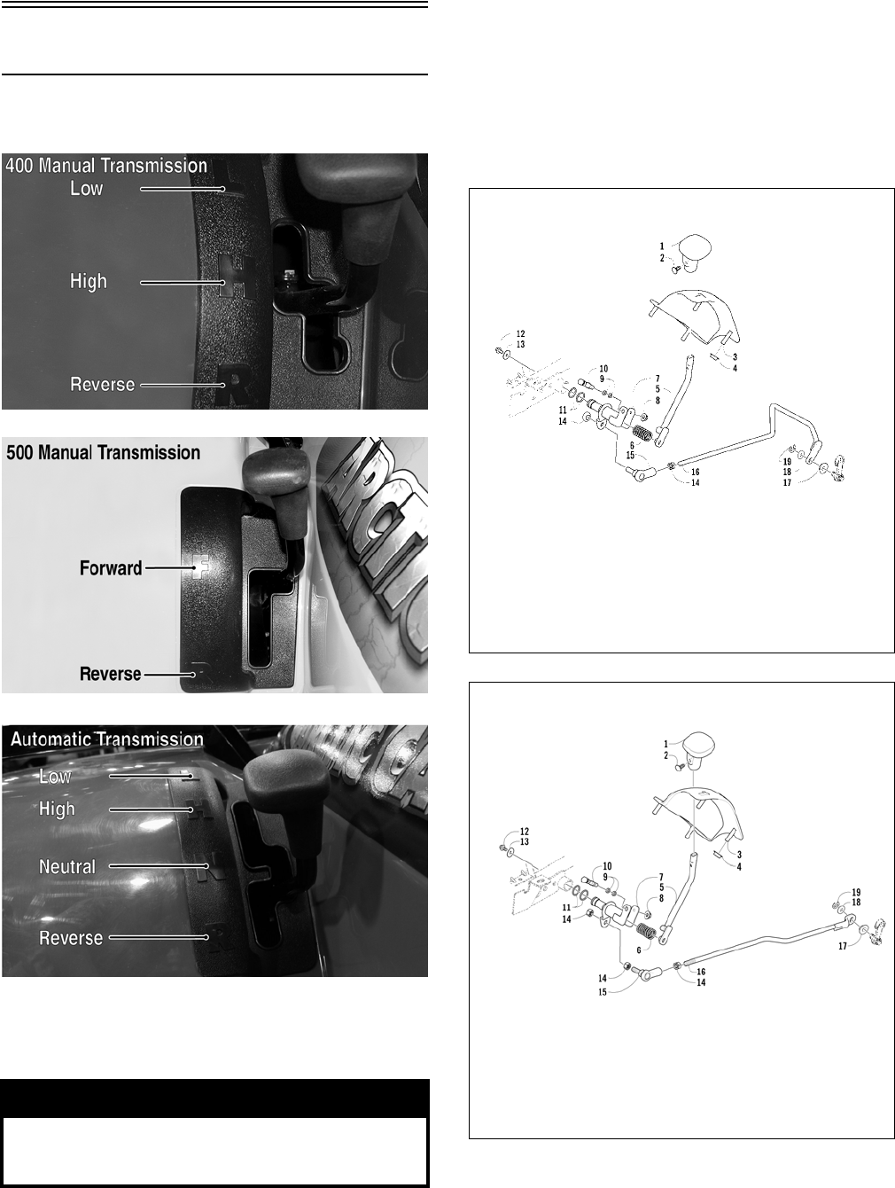
2-18
Shift Lever
CHECKING ADJUSTMENT
CF150B
CF238A
CF130A
Stop the ATV completely and shift the transmission
into the R position. The reverse gear indicator light
should be illuminated.
If the reverse light does not illuminate when shifted
to the reverse position, the switch may be faulty, the
fuse may be blown, the bulb may be faulty, a con-
nection may be loose or corroded, or the lever may
need adjusting. To adjust, proceed to Adjusting Shift
Lever.
ADJUSTING SHIFT LEVER
0739-739
0739-701
1. Place the shift lever in the R position; then
remove the seat.
NOTE: Steps 2-8 are for all models except the
700 EFI. For the 700 EFI, proceed to step 9.
! WARNING
Never shift the ATV into reverse gear when the ATV
is moving as it could cause the ATV to stop sud-
denly throwing the operator from the ATV.
KEY
1. Handle
2. Push Clip
3. Shift Plate
4. Stamped Nut
5. Lever
6. Spring
7. Axle
8. Nut
9. O-Ring
10. Axle
11. O-Ring
12. Cap Screw
13. Washer
14. Nut
15. Rod End
16. Linkage
17. Bushing
18. Washer
19. E-Ring
400/500 Manual Transmission
KEY
1. Handle
2. Push Clip
3. Shift Plate
4. Stamped Nut
5. Lever
6. Spring
7. Axle
8. Nut
9. O-Ring
10. Axle
11. O-Ring
12. Cap Screw
13. Washer
14. Nut
15. Rod End
16. Linkage
17. Bushing
18. Washer
19. E-Ring
400/500 Automatic Transmission/
650 H1/700 EFI
FOR ARCTIC CAT ATV DISCOUNT PARTS CALL 606-678-9623 OR 606-561-4983
www.mymowerparts.com
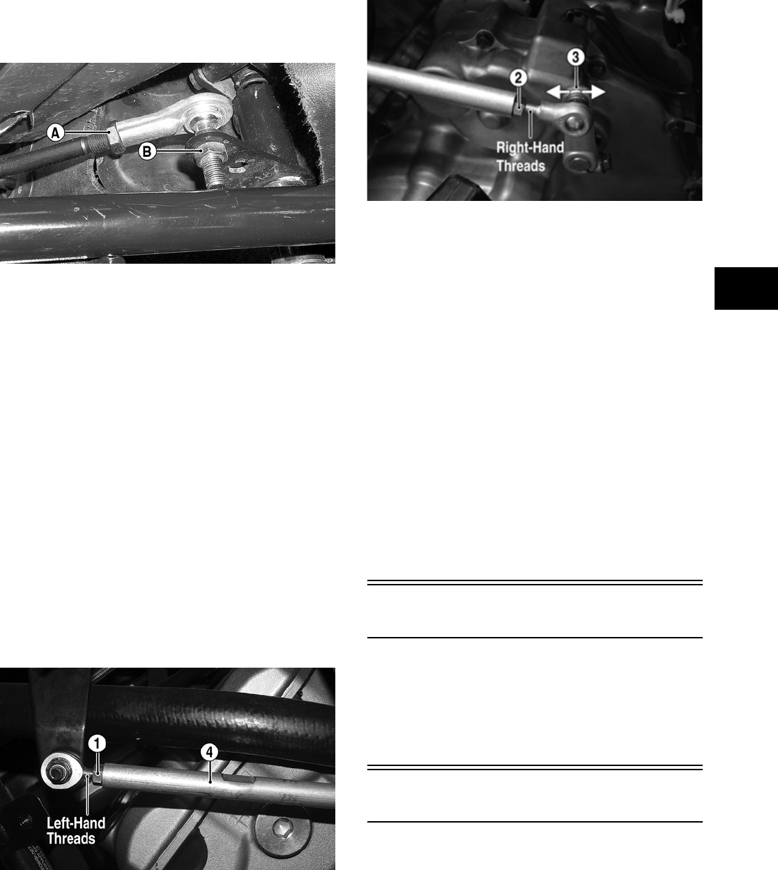
2-19
2
2. Remove the left-side splash panel.
3. Loosen shift rod end jam nut (A).
AF941A
4. Using two open-end wrenches, remove lock nut
(B) securing the shift rod to the upper shift axle.
Discard the lock nut.
NOTE: Never reuse a lock nut. Once a lock nut
has been removed, it must be replaced with a new
lock nut.
5. Push the upper shift axle down completely.
6. Rotate the shift rod end as necessary to align its
threaded shaft with the hole in the upper shift
axle. Secure with a new lock nut (B). Tighten
securely.
7. Tighten jam nut (A) to secure the adjustment.
8. Install the left-side splash panel; then install the
seat.
9. Loosen the front shift rod jam nut (1) (left-hand
threads); then loosen the rear shift rod jam nut
(2) (right-hand threads).
FI059A
FI010A
10. Turn the ignition switch to the ON position; then
move the shift arm (3) until the Neutral icon (N)
appears on the LCD.
11. Rotate the shift rod (4) until the shifter is
directly aligned with the Neutral position on the
shift gate.
12. While holding the shift rod with an open-end
wrench, tighten the shift rod jam nuts securely.
13. Shift the transmission into each of the remaining
positions and verify that the appropriate icon is
displayed for the selected gear shift position (H —
High, L — Low, and R — Reverse).
NOTE: An E (Error) in the gear position icon
indicates no signal or a poor ground wire connec-
tion in the circuit. Troubleshoot the harness con-
nectors, gear shift position connector, gear shift
position switch, and LCD connector.
Frame/Welds/Racks
The frame, welds, and racks should be checked peri-
odically for damage, bends, cracks, deterioration,
broken components, and missing components. If
replacement or repair constitutes removal, see Sec-
tion 8.
Electrical Connections
The electrical connections should be checked peri-
odically for proper function. In case of an electrical
failure, check fuses, connections (for tightness, cor-
rosion, damage), and/or bulbs. If an electrical com-
ponent needs to be tested for proper function, see
Section 5.
FOR ARCTIC CAT ATV DISCOUNT PARTS CALL 606-678-9623 OR 606-561-4983
www.mymowerparts.com
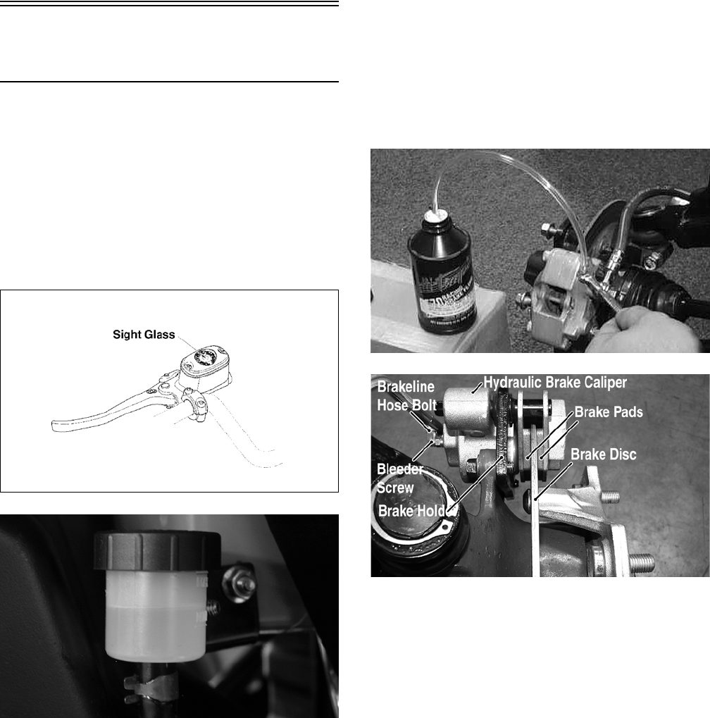
2-20
Hydraulic
Brake Systems
CHECKING/BLEEDING
The hydraulic brake systems have been filled and
bled at the factory. To check and/or bleed a hydrau-
lic brake system, use the following procedure.
1. With the master cylinder in a level position,
check the fluid level in the reservoir. If the level
in the reservoir is not visible in the sight glass,
add DOT 4 brake fluid.
738-420A
AL681
2. Compress the brake lever/pedal several times to
check for a firm brake. If the brake is not firm,
the system must be bled.
3. To bleed the brake system, use the following
procedure.
A. Remove the cover and fill the reservoir with
DOT 4 Brake Fluid.
B. Install and secure the cover; then slowly
compress the brake lever several times.
C. Remove the protective cap, install one end of
a clear hose onto one FRONT bleeder screw,
and direct the other end into a container; then
while holding slight pressure on the brake
lever, open the bleeder screw and watch for
air bubbles. Close the bleeder screw before
releasing the brake lever. Repeat this proce-
dure until no air bubbles are present.
AF637D
PR377A
NOTE: During the bleeding procedure, watch the
reservoir sight glass very closely to make sure
there is always a sufficient amount of brake fluid.
When the sight glass changes from dark to light,
refill the reservoir before the bleeding procedure is
continued. Failure to maintain a sufficient amount
of fluid in the reservoir will result in air in the sys-
tem.
D. Repeat step C until the brake lever is firm.
E. At this point, perform step B, C, and D on the
other FRONT bleeder screw; then move to
the REAR bleeder screw and follow the same
procedure.
4. Carefully check the entire hydraulic brake system
that all hose connections are tight, the bleed
screws are tight, the protective caps are installed,
and no leakage is present.
FOR ARCTIC CAT ATV DISCOUNT PARTS CALL 606-678-9623 OR 606-561-4983
www.mymowerparts.com
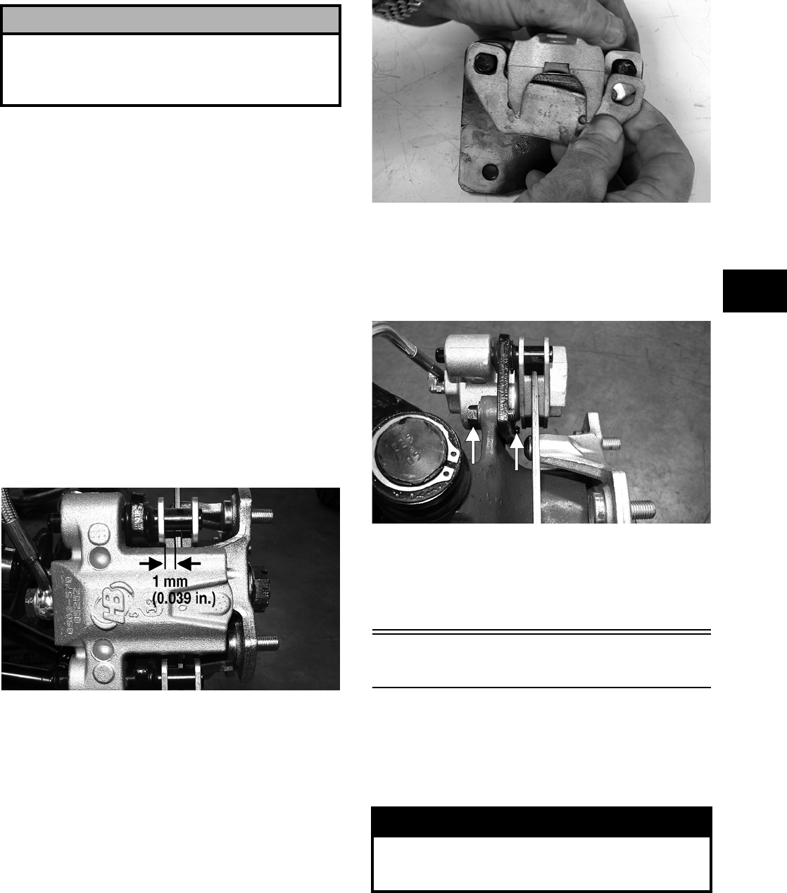
2-21
2
INSPECTING HOSES
Carefully inspect the hydraulic brake hoses for
cracks or other damage. If found, the brake hoses
must be replaced.
CHECKING/REPLACING PADS
The clearance between the brake pads and brake
discs is adjusted automatically as the brake pads
wear. The only maintenance that is required is
replacement of the brake pads when they show
excessive wear. Check the thickness of each of the
brake pads as follows.
1. Remove a front wheel.
2. Measure the thickness of each brake pad.
3. If thickness of either brake pad is less than 1.0
mm (0.039 in.), the brake pads must be replaced.
PR376B
NOTE: The brake pads should be replaced as a
set.
4. To replace the brake pads, use the following pro-
cedure.
A. Remove the wheel.
B. Remove the cap screws securing the caliper
holder to the knuckle; then remove the pads.
PR237
C. Install the new brake pads.
D. Secure the caliper to the knuckle and/or axle
housing with the cap screws. Tighten to spec-
ifications.
PR377B
E. Install the wheel. Tighten to specifications.
5. Burnish the brake pads (see Burnishing Brake
Pads in this section).
Burnishing Brake Pads
Brake pads (both hydraulic and auxiliary) must be
burnished to achieve full braking effectiveness.
Braking distance will be extended until brake pads
are properly burnished. To properly burnish the
brake pads, use the following procedure.
1. Choose an area large enough to safely accelerate
the ATV to 30 mph and to brake to a stop.
2. Accelerate to 30 mph; then compress brake
lever or apply the auxiliary brake to decelerate
to 0-5 mph.
! CAUTION
This hydraulic brake system is designed to use DOT
4 brake fluid only. If brake fluid must be added, care
must be taken as brake fluid is very corrosive to
painted surfaces.
! WARNING
Failure to properly burnish the brake pads could
lead to premature brake pad wear or brake loss.
Brake loss can result in severe injury.
FOR ARCTIC CAT ATV DISCOUNT PARTS CALL 606-678-9623 OR 606-561-4983
www.mymowerparts.com
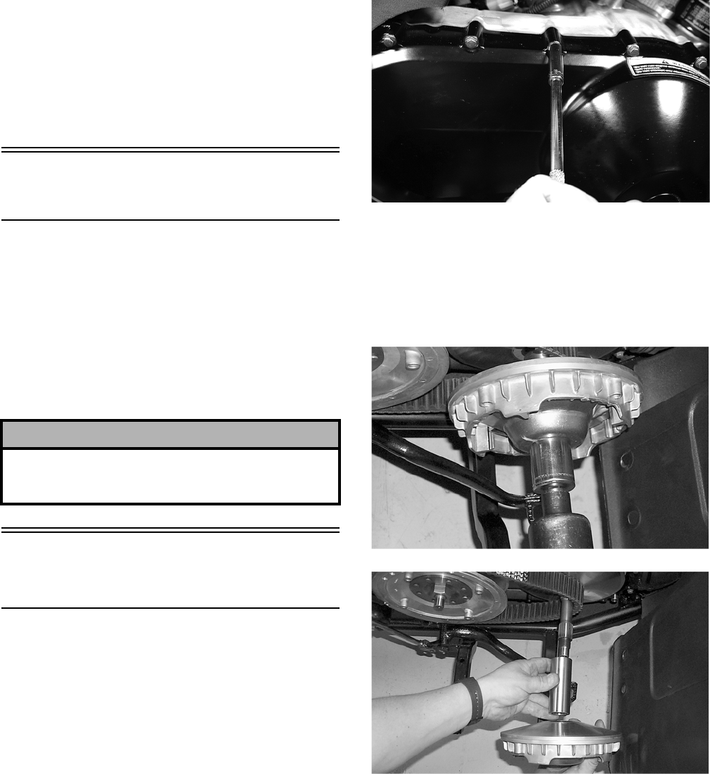
2-22
3. Repeat procedure on each brake system five
times until brake pads are burnished.
4. Adjust the auxiliary brake (if necessary).
5. Verify that the brakelight illuminates when the
hand lever is compressed or the brake pedal is
depressed.
Coolant
(500/650 H1/700 EFI)
The cooling system should be inspected daily for
leakage and damage. Also, the coolant level should
be checked periodically.
When filling the cooling system, use premixed Arc-
tic Cat Antifreeze. While the cooling system is
being filled, air pockets may develop; therefore, run
the engine for five minutes after the initial fill, shut
the engine off, and then fill the cooling system to the
bottom of the stand pipe in the radiator neck.
Checking/Replacing
V-Belt
REMOVING
1. Remove the right-side footrest (see Section 8).
2. Remove the cap screws securing the V-belt
cover noting the location of the differ-
ent-lengthed cap screws for installing purposes;
then using a rubber mallet, gently tap on the
cover tabs to loosen the cover. Remove the
cover.
CD078
NOTE: Note the location of the main engine
ground wire for installing purposes.
3. Remove the nut securing the movable drive
face; then remove the face. Account for the
spacer.
CC546
CC547
4. Remove the V-belt.
! CAUTION
After operating the ATV for the initial 5-10 minutes,
stop the engine, allow the engine to cool down, and
check the coolant level. Add coolant as necessary.
FOR ARCTIC CAT ATV DISCOUNT PARTS CALL 606-678-9623 OR 606-561-4983
www.mymowerparts.com
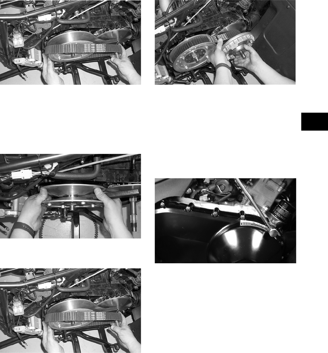
2-23
2
CC550
INSTALLING
1. Spread the faces of the driven clutch by pushing
the inner face toward the engine while turning it
counterclockwise; then when the faces are sepa-
rated, insert a wedge (approximately 3/8 in.
thick) between the faces. Release the inner face.
CC549
2. Place the V-belt into position on the driven
clutch and over the front shaft.
CC550
NOTE: The arrow on the V-belt should point for-
ward.
3. Pinch the V—belt together near its center and
slide the spacer and movable drive face onto the
driveshaft. Secure the drive face with a nut.
Tighten the nut to specifications (see Section
10).
CC552
NOTE: At this point, the wedge can be removed
from between the driven clutch faces.
4. Rotate the V-belt and clutches until the V-belt is
flush with the top of the driven clutch.
5. Place the V-belt cover gasket into position; then
install the cover and secure with the cap screws
making sure the different-lengthed cap screws
are in their proper location. Tighten the cap
screws to specifications (see Section 10).
CD083
NOTE: Make sure the main engine ground wire
is installed and secured in the proper location.
6. Secure the front fender to the footrest with the
two cap screws. Tighten securely.
7. Install the right-side footrest (see Section 8).
FOR ARCTIC CAT ATV DISCOUNT PARTS CALL 606-678-9623 OR 606-561-4983
www.mymowerparts.com
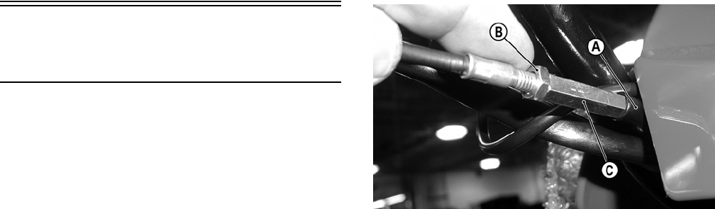
2-24
Adjusting Differential
Lock Cable
NOTE: The following procedure does not
include the 400 TRV model.
If the differential or differential lock system has
been serviced, the differential lock cable should be
checked and/or adjusted for proper free-play.
To adjust the cable, use the following procedure.
1. With the differential lock selector in the
UNLOCK position, slide the rubber boot (A) off
the adjuster; then loosen the jam nut (B). Turn
the adjuster (C) to achieve 6.35 mm (0.250 in.)
of free-play measured at the end of the differen-
tial lock lever.
CD560A
2. Select the 2WD position on the front drive
selector switch; then turn the ignition switch to
the ON position and select the LOCK position
on the differential lock selector. The front drive
actuator should operate engaging four-wheel
drive.
NOTE: It may be necessary to turn the handle-
bar or rock the ATV forward and backward to align
the differential lock splines and allow engagement.
3. Return the differential lock selector to the
UNLOCK position and listen for the front drive
actuator to operate.
4. Turn the ignition switch to the OFF position.
Tighten the jam nut securely; then install the
boot on the adjuster.
FOR ARCTIC CAT ATV DISCOUNT PARTS CALL 606-678-9623 OR 606-561-4983
www.mymowerparts.com
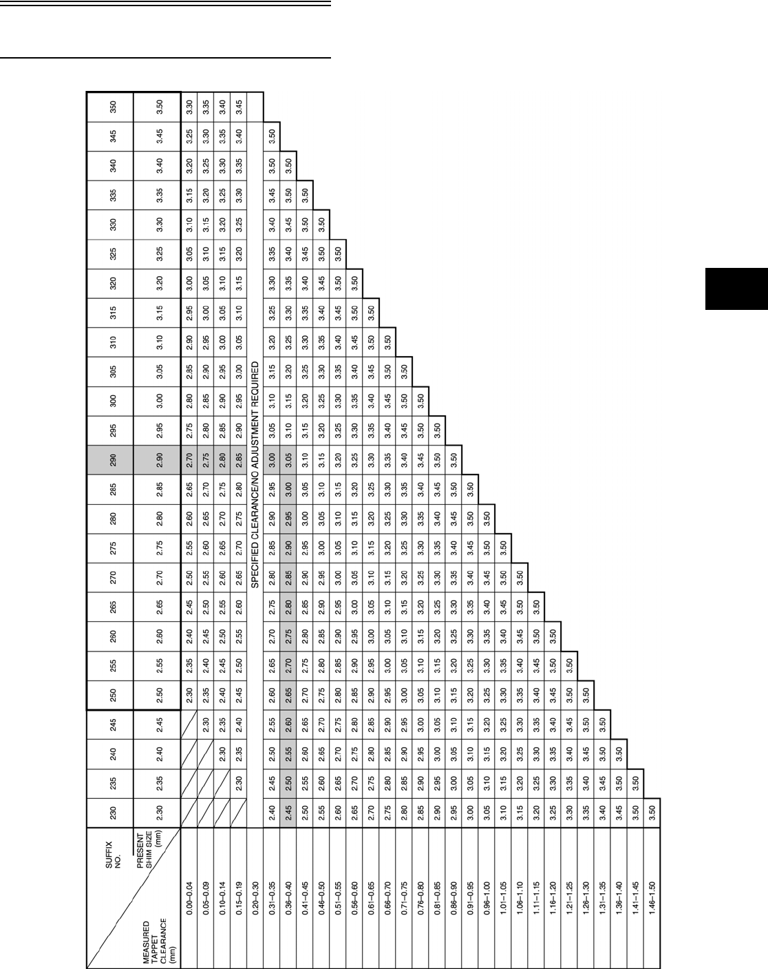
2-25
2
Exhaust Chart
NOTE: Use this chart in conjunction with the
procedure found in Valve/Tappet Clearance (700
EFI) in this section.
ATV2152A
FOR ARCTIC CAT ATV DISCOUNT PARTS CALL 606-678-9623 OR 606-561-4983
www.mymowerparts.com
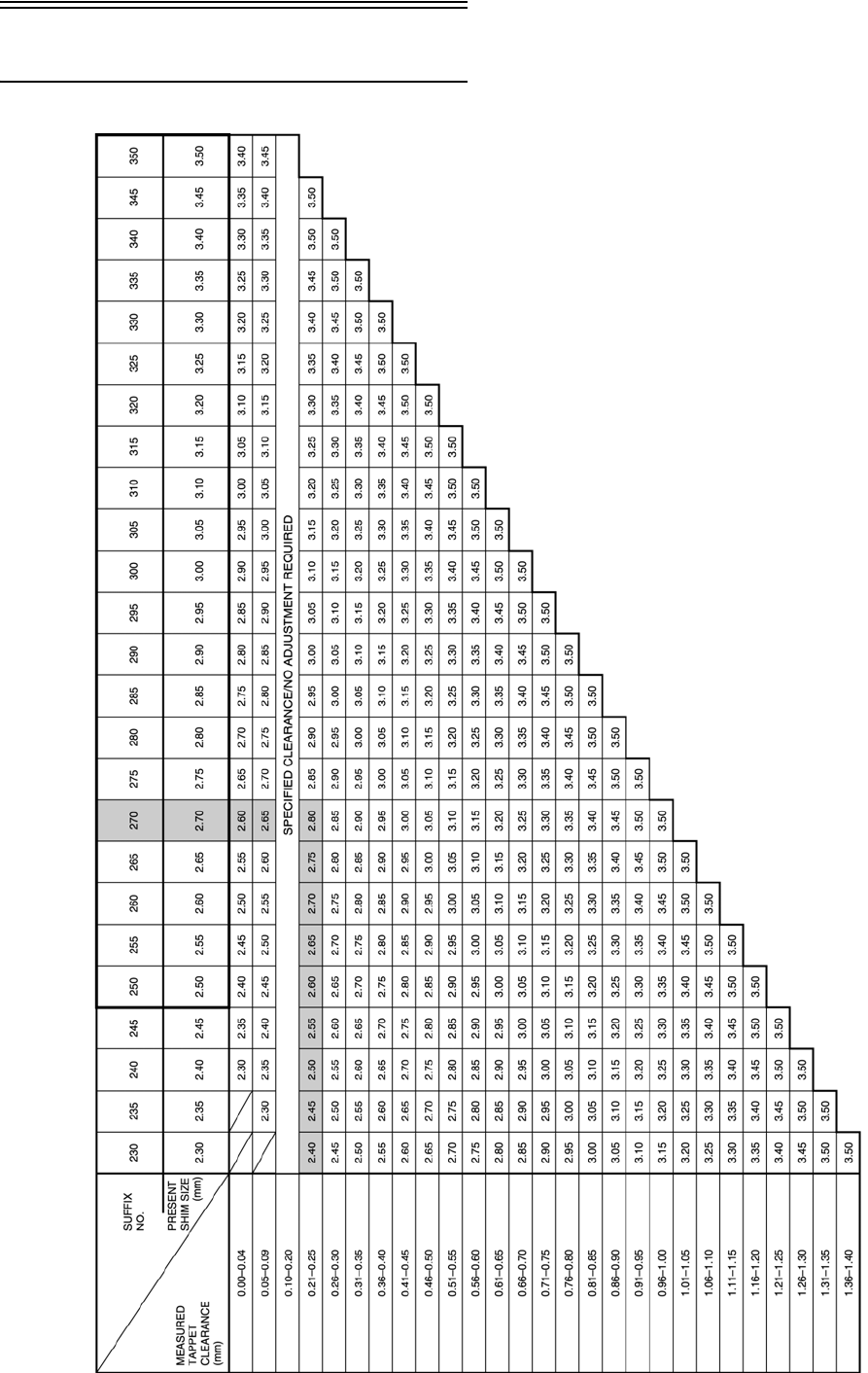
2-26
Intake Chart NOTE: Use this chart in conjunction with the
procedure found in Valve/Tappet Clearance (700
EFI) in this section.
FOR ARCTIC CAT ATV DISCOUNT PARTS CALL 606-678-9623 OR 606-561-4983
www.mymowerparts.com

3-1
3
SECTION 3 — ENGINE/TRANSMISSION
TABLE OF
CONTENTS
Engine/Transmission ……….…………….…………….….. 3-2
Specifications (400 — Automatic Transmission)…….. 3-3
Specifications (400 — Manual Transmission).……….. 3-4
Specifications (500 — Automatic Transmission)…….. 3-6
Specifications (500 — Manual Transmission).……….. 3-7
Specifications (650 H1) ……………………….…………… 3-9
Specifications (700 EFI) ………..…………….…………. 3-10
400 (Manual Transmission)
Table of Contents ……………..………….…………….… 3-11
400 (Automatic Transmission)
Table of Contents ……………..………….…………….… 3-76
500 (Automatic Transmission)/650 H1
Table of Contents ……………..………….…………….. 3-130
500 (Manual Transmission)
Table of Contents ……………..………….…………….. 3-185
700 EFI Table of Contents……………………….……. 3-256
FOR ARCTIC CAT ATV DISCOUNT PARTS CALL 606-678-9623 OR 606-561-4983
www.mymowerparts.com

3-2
Engine/Transmission
This section has been organized into sub-sections
which show a progression for the complete servic-
ing of the Arctic Cat ATV engine/transmission.
To service the center crankcase halves, the
engine/transmission must be removed from the
frame.
To service top-side, left-side, and right-side compo-
nents, the engine/transmission does not have to be
removed from the frame.
NOTE: Arctic Cat recommends the use of new
gaskets, lock nuts, and seals and lubricating all
internal components when servicing the
engine/transmission.
NOTE: Some photographs and illustrations used
in this section are used for clarity purposes only
and are not designed to depict actual conditions.
NOTE: Critical torque specifications are located
in Section 10.
FOR ARCTIC CAT ATV DISCOUNT PARTS CALL 606-678-9623 OR 606-561-4983
www.mymowerparts.com

3-3
3
Specifications*
(400 — Automatic Transmission)
* Specifications subject to change without notice.
VALVES AND GUIDES
Valve Face Diameter (intake)
(exhaust)
30.6 mm (1.20 in.)
27.0 mm (1.06 in.)
Valve/Tappet Clearance
(cold engine)
(intake)
(exhaust)
0.05-0.10 mm
(0.002-0.004 in.)
0.22-0.27 mm
(0.009-0.011 in.)
Valve Guide/Stem
Clearance
(intake)
(exhaust)
0.010-0.037 mm
(0.0004-0.0015 in.)
0.030-0.057 mm
(0.0012-0.0022 in.)
Valve Guide/Valve Stem
Deflection
(wobble deflection)
(max) 0.35 mm (0.014 in.)
Valve Guide Inside Diameter 5.000-5.012 mm
(0.1969-0.1973 in.)
Valve Stem Outside
Diameter
(intake)
(exhaust)
4.975-4.990 mm
(0.1959-0.1965 in.)
4.955-4.970 mm
(0.1951-0.1957 in.)
Valve Stem Runout (max) 0.05 mm (0.002 in.)
Valve Head Thickness (min) 0.5 mm (0.02 in.)
Valve Stem End Length (min) 2.3 mm (0.09 in.)
Valve Face/Seat Width 0.9-1.1 mm
(0.035-0.043 in.)
Valve Seat Angle (intake)
(exhaust)
45°
45°
Valve Face Radial Runout (max) 0.03 mm (0.001 in.)
Valve Spring Free Length (min) 38.8 mm (1.53 in.)
Valve Spring Tension
@ 32.5 mm (1.28 in.)
(outer) 18.6-21.4 kg
(41-47 lb)
CAMSHAFT AND CYLINDER HEAD
Cam Lobe Height (min) (intake)
(exhaust)
32.830 mm
(1.293 in.)
32.830 mm
(1.293 in.)
Camshaft Journal Oil
Clearance
(max) 0.15 mm (0.0059 in.)
Camshaft Journal Holder
Inside
(right & center)
(left)
22.012-22.025 mm
(0.8666-0.8671 in.)
17.512-17.525 mm
(0.6894-0.6900 in.)
Camshaft Journal
Outside Diameter
(right & center)
(left)
21.959-21.980 mm
(0.8645-0.8654 in.)
17.466-17.484 mm
(0.6876-0.6883 in.)
Camshaft Runout (max) 0.10 mm (0.004 in.)
Rocker Arm Inside Diameter 12.000-12.018 mm
(0.472-0.473 in.)
Rocker Arm Shaft Outside Diameter 11.973-11.984 mm
(0.4714-0.4718 in.)
Cylinder Head Distortion (max) 0.05 mm (0.002 in.)
Cylinder Head Cover
Distortion
(max) 0.05 mm (0.002 in.)
CYLINDER, PISTON, AND RINGS
Piston Skirt/Cylinder Clearance 0.060-0.073 mm
(0.0024-0.0029 in.)
Cylinder Bore 82.000-82.015 mm
(3.2283-3.2289 in.)
Piston Diameter 15 mm (0.6 in.)
from Skirt End
81.930-81.945 mm
(3.2256-3.2262 in.)
Piston Ring Free End Gap
(min)
(1st Ring)
(2nd Ring)
8.9 mm
(0.3504 in.)
8.3 mm
(0.3268 in.)
Bore x Stroke 82 x 71.2 mm
(3.29 x 2.80 in.)
Cylinder Trueness (max) 0.05 mm (0.002 in.)
Piston Ring End Gap — Installed 0.33-0.61 mm
(0.013-0.024 in.)
Piston Ring to Groove
Clearance (max)
(1st)
(2nd)
0.180 mm
(0.0071 in.)
0.150 mm
(0.0059 in.)
Piston Ring Groove Width (1st)
(2nd)
(oil)
1.01-1.03 mm
(0.0398-0.0406 in.)
1.01-1.03 mm
(0.0398-0.0406 in.)
2.01-2.03 mm
(0.0791-0.0799 in.)
Piston Ring Thickness (1st)
(2nd)
0.97-0.99 mm
(0.0381-0.0389 in.)
0.97-0.99 mm
(0.0381-0.0389 in.)
Piston Pin Bore (max) 20.03 mm (0.789 in.)
Piston Pin Outside Diameter (min) 19.98 mm (0.787 in.)
CRANKSHAFT
Connecting Rod
(small end inside diameter)
(max) 20.04 mm
(0.7889 in.)
Connecting Rod
(big end side-to-side)
0.10-0.55 mm
(0.004-0.022 in.)
Connecting Rod (big end width) 21.95-22.00 mm
(0.8642-0.8661 in.)
Connecting Rod
(small end deflection)
(max) 3 mm (0.12 in.)
Crankshaft (web-to-web) 59.9-60.1 mm
(2.358-2.366 in.)
Crankshaft Runout (max) 0.08 mm (0.003 in.)
Oil Pressure at 60°C
(140°F) @ 3000 RPM
(above)
(below)
1.1 kg/cm² (16 psi)
1.5 kg/cm² (21 psi)
Cooling Fan Thermo-Switch
Operating Temperature
(off J on)
(on J off)
120°C (248°F)
110°C (230°F)
Engine Oil Thermo-Switch
Operating Temperature
(off J on)
(on J off)
160°C (320°F)
140°C (284°F)
FOR ARCTIC CAT ATV DISCOUNT PARTS CALL 606-678-9623 OR 606-561-4983
www.mymowerparts.com

3-4
Specifications*
(400 — Manual Transmission)
VALVES AND GUIDES
Valve Face Diameter (intake)
(exhaust)
30.6 mm (1.20 in.)
27.0 mm (1.06 in.)
Valve/Tappet Clearance
(cold engine)
(intake)
(exhaust)
0.05-0.10 mm
(0.002-0.004 in.)
0.22-0.27 mm
(0.009-0.011 in.)
Valve Guide/Stem
Clearance
(intake)
(exhaust)
0.010-0.037 mm
(0.0004-0.0015 in.)
0.030-0.057 mm
(0.0012-0.0022 in.)
Valve Guide/Valve Stem
Deflection
(wobble deflection)
(max) 0.35 mm (0.014 in.)
Valve Guide Inside Diameter 5.000-5.012 mm
(0.1969-0.1973 in.)
Valve Stem Outside
Diameter
(intake)
(exhaust)
4.975-4.990 mm
(0.1959-0.1965 in.)
4.955-4.970 mm
(0.1951-0.1957 in.)
Valve Stem Runout (max) 0.05 mm (0.002 in.)
Valve Head Thickness (min) 0.5 mm (0.02 in.)
Valve Stem End Length (min) 2.3 mm (0.09 in.)
Valve Face/Seat Width 0.9-1.1 mm
(0.035-0.043 in.)
Valve Seat Angle (intake)
(exhaust)
45°
45°
Valve Face Radial
Runout
(max) 0.03 mm (0.001 in.)
Valve Spring Free Length (min) 38.8 mm (1.53 in.)
Valve Spring Tension
@ 32.5 mm (1.28 in.)
(outer) 18.6-21.4 kg
(41-47 lb)
CAMSHAFT AND CYLINDER HEAD
Cam Lobe Height (min) (intake)
(exhaust)
32.830 mm (1.293 in.)
32.830 mm (1.293 in.)
Camshaft Journal Oil
Clearance
(max) 0.15 mm (0.0059 in.)
Camshaft Journal Holder
Inside
(right & center)
(left)
22.012-22.025 mm
(0.8666-0.8671 in.)
17.512-17.525 mm
(0.6894-0.6900 in.)
Camshaft Journal
Outside Diameter
(right & center)
(left)
21.959-21.980 mm
(0.8645-0.8654 in.)
17.466-17.484 mm
(0.6876-0.6883 in.)
Camshaft Runout (max) 0.10 mm (0.004 in.)
Rocker Arm Inside Diameter 12.000-12.018 mm
(0.472-0.473 in.)
Rocker Arm Shaft Outside Diameter 11.973-11.984 mm
(0.4714-0.4718 in.)
Cylinder Head Distortion (max) 0.05 mm (0.002 in.)
Cylinder Head Cover
Distortion
(max) 0.05 mm (0.002 in.)
CYLINDER, PISTON, AND RINGS
Piston Skirt/Cylinder
Clearance
0.060-0.073 mm
(0.0024-0.0029 in.)
Cylinder Bore 82.000-82.015 mm
(3.2283-3.2289 in.)
Piston Diameter 15 mm (0.6 in.) from
Skirt End
81.930-81.945 mm
(3.2256-3.2262 in.)
Piston Ring Free End Gap
(min)
(1st Ring)
(2nd Ring)
8.9 mm
(0.3504 in.)
8.3 mm
(0.3268 in.)
Bore x Stroke 82 x 71.2 mm
(3.29 x 2.80 in.)
Cylinder Trueness (max) 0.05 mm (0.002 in.)
Piston Ring End Gap — Installed 0.33-0.61 mm
(0.013-0.024 in.)
Piston Ring to Groove
Clearance (max)
(1st)
(2nd)
0.180 mm
(0.0071 in.)
0.150 mm
(0.0059 in.)
Piston Ring Groove Width (1st)
(2nd)
(oil)
1.01-1.03 mm
(0.0398-0.0406 in.)
1.01-1.03 mm
(0.0398-0.0406 in.)
2.01-2.03 mm
(0.0791-0.0799 in.)
Piston Ring Thickness (1st)
(2nd)
0.97-0.99 mm
(0.0381-0.0389 in.)
0.97-0.99 mm
(0.0381-0.0389 in.)
Piston Pin Bore (max) 20.03 mm (0.789 in.)
Piston Pin Outside Diameter (min) 19.98 mm (0.787 in.)
CRANKSHAFT
Connecting Rod
(small end inside diameter)
(max) 20.04 mm
(0.7889 in.)
Connecting Rod
(big end side-to-side)
0.10-0.55 mm
(0.004-0.022 in.)
Connecting Rod (big end width) 21.95-22.00 mm
(0.8642-0.8661 in.)
Connecting Rod
(small end deflection)
(max) 3 mm (0.12 in.)
Crankshaft (web-to-web) 59.9-60.1 mm
(2.358-2.366 in.)
Crankshaft Runout (max) 0.08 mm (0.003 in.)
Oil Pressure at 60°C
(140°F) @ 3000 RPM
(above)
(below)
0.6 kg/cm² (9 psi)
1.0 kg/cm² (14 psi)
Cooling Fan Thermo-Switch
Operating Temperature
(off J on)
(on J off)
120°C (248°F)
110°C (230°F)
Engine Oil Thermo-Switch
Operating Temperature
(off J on)
(on J off)
160°C (320°F)
140°C (284°F)
FOR ARCTIC CAT ATV DISCOUNT PARTS CALL 606-678-9623 OR 606-561-4983
www.mymowerparts.com

3-5
3
* Specifications subject to change without notice.
CLUTCH
Clutch Release Screw 1/8 turn back
Drive Plate (fiber) Thickness (min) 2.62 mm (0.103 in.)
Drive Plate (fiber) Tab 13.25-13.95 mm
(0.52-0.55 in.)
Driven Plate (warpage) (max) 0.1 mm (0.004 in.)
Clutch Spring Length (min) 33.7 mm (1.33 in.)
Clutch Wheel Inside Diameter 140.0-140.2 mm
(5.511-5.520 in.)
Starter Clutch Shoe No groove at any part
Clutch Engagement RPM 1700 ± 200
Clutch Lock-Up RPM 3400 — 4000
Primary Reduction Ratio 2.392 (67/28)
Secondary Reduction Ratio 1.133 (17/15)
Final Reduction Ratio (front)
(rear)
3.6 (36/10)
3.6 (36/10)
Secondary Transmission
Reduction Ratio
(low)
(high)
2.435 (35/13 x 19/21)
1.296 (35/27)
Gear Ratios (1st)
(2nd)
(3rd)
(4th)
(5th)
(reverse)
3.083 (37/12)
1.933 (29/15)
1.388 (25/18)
1.095 (23/21)
0.913 (21/23)
2.833 (34/12)
Engine Fork to Groove
(side clearance)
0.1-0.3 mm
(0.004-0.012 in.)
Secondary Transmission Fork to Groove
(side clearance)
0.1-0.3 mm
(0.004-0.012 in.)
Reverse Fork to Groove
(side clearance)
0.1-0.3 mm
(0.004-0.012 in.)
Shift Fork Groove Width (#1 and #2) 4.5-4.6 mm
(0.177-0.181 in.)
(secondary transmission)
(reverse)
5.45-5.55 mm
(0.215-0.219 in.)
4.0-4.1 mm
(0.157-0.161 in.)
Shift Fork Thickness (#1 and #2)
(secondary transmission)
(reverse)
4.3-4.4 mm
(0.169-0.173 in.)
5.3-5.4 mm
(0.209-0.213 in.)
3.8-3.9 mm
(0.150-0.154 in.)
FOR ARCTIC CAT ATV DISCOUNT PARTS CALL 606-678-9623 OR 606-561-4983
www.mymowerparts.com

3-6
Specifications*
(500 — Automatic Transmission)
* Specifications subject to change without notice.
VALVES AND GUIDES
Valve Face Diameter (intake)
(exhaust)
30.6 mm (1.20 in.)
27.0 mm (1.06 in.)
Valve/Tappet Clearance
(cold engine)
(intake)
(exhaust)
0.05-0.10 mm
(0.002-0.004 in.)
0.17-0.22 mm
(0.007-0.009 in.)
Valve Guide/Stem
Clearance
(intake)
(exhaust)
0.010-0.037 mm
(0.0004-0.0015 in.)
0.030-0.057 mm
(0.0012-0.0022 in.)
Valve Guide/Valve Stem
Deflection
(wobble deflection)
(max) 0.35 mm (0.014 in.)
Valve Guide Inside Diameter 5.000-5.012 mm
(0.1969-0.1973 in.)
Valve Stem Outside
Diameter
(intake)
(exhaust)
4.975-4.990 mm
(0.1959-0.1965 in.)
4.955-4.970 mm
(0.1951-0.1957 in.)
Valve Stem Runout (max) 0.05 mm (0.002 in.)
Valve Head Thickness (min) 0.5 mm (0.02 in.)
Valve Stem End Length (min) 2.3 mm (0.09 in.)
Valve Face/Seat Width 0.9-1.1 mm
(0.035-0.043 in.)
Valve Seat Angle (intake)
(exhaust)
45°
45°
Valve Face Radial Runout (max) 0.03 mm (0.001 in.)
Valve Spring Free Length (min) 38.8 mm (1.53 in.)
Valve Spring Tension
@ 31.5 mm (1.24 in.)
(outer) 18.6-21.4 kg
(41-47 lb)
CAMSHAFT AND CYLINDER HEAD
Cam Lobe Height (min) (intake)
(exhaust)
33.13 mm (1.304 in.)
33.20 mm (1.307 in.)
Camshaft Journal Oil
Clearance
(max) 0.15 mm (0.0059 in.)
Camshaft Journal Holder
Inside
(right & center)
(left)
22.012-22.025 mm
(0.8666-0.8671 in.)
17.512-17.525 mm
(0.6894-0.6900 in.)
Camshaft Journal
Outside Diameter
(right & center)
(left)
21.959-21.980 mm
(0.8645-0.8654 in.)
17.466-17.484 mm
(0.6876-0.6883 in.)
Camshaft Runout (max) 0.10 mm (0.004 in.)
Rocker Arm Inside Diameter 12.000-12.018 mm
(0.472-0.473 in.)
Rocker Arm Shaft Outside Diameter 11.973-11.984 mm
(0.4714-0.4718 in.)
Cylinder Head Distortion (max) 0.05 mm (0.002 in.)
Cylinder Head Cover
Distortion
(max) 0.05 mm (0.002 in.)
CYLINDER, PISTON, AND RINGS
Piston Skirt/Cylinder
Clearance
0.030-0.040 mm
(0.0011-0.0015 in.)
Cylinder Bore 87.500-87.515 mm
(3.4448-3.4454 in.)
Piston Diameter 15 mm (0.6 in.) from Skirt
End
87.465-87.480 mm
(3.4435-3.4440 in.)
Piston Ring Free End Gap
(min)
(1st Ring)
(2nd Ring)
9.0 mm
(0.35 in.)
9.5 mm
(0.37 in.)
Bore x Stroke 87.5 x 82 mm
(3.40 x 3.22 in.)
Cylinder Trueness (max) 0.05 mm (0.002 in.)
Piston Ring End Gap — Installed 0.35-0.63 mm
(0.014-0.025 in.)
Piston Ring to Groove
Clearance (max)
(1st)
(2nd)
0.180 mm
(0.0071 in.)
0.150 mm
(0.0059 in.)
Piston Ring Groove Width (1st)
(2nd)
(oil)
1.01-1.03 mm
(0.0398-0.0406 in.)
1.21-1.23 mm
(0.0476-0.0484 in.)
2.51-2.53 mm
(0.0988-0.0996 in.)
Piston Ring Thickness (1st)
(2nd)
0.97-0.99 mm
(0.0382-0.0389 in.)
1.17-1.19 mm
(0.046-0.047 in.)
Piston Pin Bore (max) 23.03 mm (0.907 in.)
Piston Pin Outside Diameter (min) 22.98 mm (0.905 in.)
CRANKSHAFT
Connecting Rod
(small end inside diameter)
(max) 23.04 mm
(0.9070 in.)
Connecting Rod
(big end side-to-side)
0.10-0.65 mm
(0.0039-0.0256 in.)
Connecting Rod (big end width) 24.95-25.00 mm
(0.9822-0.9842 in.)
Connecting Rod
(small end deflection)
(max) 3 mm (0.12 in.)
Crankshaft (web-to-web) 70.9-70.1 mm
(2.796-2.804in.)
Crankshaft Runout (max) 0.08 mm (0.003 in.)
Oil Pressure at 60°C
(140°F) @ 3000 RPM
(above)
(below)
1.3 kg/cm² (18 psi)
1.7 kg/cm² (24 psi)
Cooling Fan Thermo-Switch
Operating Temperature
(off J on)
(on J off)
88°C (190°F)
82°C (180°F) (min)
Engine Coolant Thermo-Switch
Operating Temperature
(off J on)
(on J off)
(approx)
115°C (239°F)
108°C (226°F)
FOR ARCTIC CAT ATV DISCOUNT PARTS CALL 606-678-9623 OR 606-561-4983
www.mymowerparts.com

3-7
3
Specifications*
(500 — Manual Transmission)
VALVES AND GUIDES
Valve Face Diameter (intake)
(exhaust)
30.6 mm (1.20 in.)
27.0 mm (1.06 in.)
Valve/Tappet Clearance
(cold engine)
(intake)
(exhaust)
0.05-0.10 mm
(0.002-0.004 in.)
0.17-0.22 mm
(0.007-0.009 in.)
Valve Guide/
Stem Clearance
(intake)
(exhaust)
0.010-0.037 mm
(0.0004-0.0015 in.)
0.030-0.057 mm
(0.0012-0.0022 in.)
Valve Guide/Valve
Stem Deflection
(wobble deflection)
(max) 0.35 mm (0.014 in.)
Valve Guide Inside Diameter 5.000-5.012 mm
(0.1969-0.1973 in.)
Valve Stem Outside Diame-
ter
(intake)
(exhaust)
4.975-4.990 mm
(0.1959-0.1965 in.)
4.955-4.970 mm
(0.1951-0.1957 in.)
Valve Stem Runout (max) 0.05 mm (0.002 in.)
Valve Head Thickness (min) 0.5 mm (0.02 in.)
Valve Stem End Length (min) 1.7 mm (0.067 in.)
Valve Face/Seat Width 0.9-1.1 mm
(0.035-0.043 in.)
Valve Seat Angle (intake)
(exhaust)
45°
45°
Valve Face Radial Runout (max) 0.03 mm (0.001 in.)
Valve Spring Free Length (min) 38.8 mm (1.53 in.)
Valve Spring Tension
@ 31.5 mm (1.24 in.)
(outer) 18.2-21.0 kg
(40.1-46.3 lb)
CAMSHAFT AND CYLINDER HEAD
Cam Lobe Height
(min)
(intake)
(exhaust)
33.13 mm (1.304 in.)
33.20 mm (1.307 in.)
Camshaft Journal Oil
Clearance
(max) 0.15 mm (0.0059 in.)
Camshaft Journal
Holder Inside
(right & center)
(left)
22.012-22.025 mm
(0.8666-0.8671 in.)
17.512-17.525 mm
(0.6894-0.6900 in.)
Camshaft Journal
Outside Diameter
(right & center)
(left)
21.959-21.980 mm
(0.8645-0.8654 in.)
17.466-17.484 mm
(0.6876-0.6883 in.)
Camshaft Runout (max) 0.10 mm (0.004 in.)
Rocker Arm Inside
Diameter
12.000-12.018 mm
(0.472-0.473 in.)
Rocker Arm Shaft Outside Diameter 11.973-11.984 mm
(0.4714-0.4718 in.)
Cylinder Head Distor-
tion
(max) 0.05 mm (0.002 in.)
Cylinder Head Cover
Distortion
(max) 0.05 mm (0.002 in.)
CYLINDER, PISTON, AND RINGS
Piston Skirt/Cylinder
Clearance
0.030-0.040 mm
(0.0011-0.0015 in.)
Cylinder Bore 87.500-87.515 mm
(3.4448-3.4454 in.)
Piston Diameter
15 mm (0.6 in.) from Skirt End
87.465-87.480 mm
(3.4435-3.4440 in.)
Piston Ring
Free End Gap (min)
(1st Ring)
(2nd Ring)
9.0 mm
(0.35 in.)
9.5 mm
(0.37 in.)
Bore x Stroke 87.5 x 82 mm
(3.40 x 3.22 in.)
Cylinder Trueness (max) 0.05 mm (0.002 in.)
Piston Ring End Gap —
Installed
0.35-0.63 mm
(0.014-0.025 in.)
Piston Ring to Groove
Clearance (max)
(1st)
(2nd)
0.180 mm
(0.0071 in.)
0.150 mm
(0.0059 in.)
Piston Ring Groove Width (1st)
(2nd)
(oil)
1.01-1.03 mm
(0.0398-0.0406 in.)
1.21-1.23 mm
(0.0476-0.0484 in.)
2.51-2.53 mm
(0.0988-0.0996 in.)
Piston Ring Thickness (1st)
(2nd)
0.97-0.99 mm
(0.0382-0.0389 in.)
1.17-1.19 mm
(0.046-0.047 in.)
Piston Pin Bore (max) 23.03 mm (0.907 in.)
Piston Pin Outside Diame-
ter
(min) 22.98 mm (0.905 in.)
CRANKSHAFT
Connecting Rod
(small end inside diameter)
(max) 23.04 mm
(0.9070 in.)
Connecting Rod
(big end side-to-side)
0.10-0.65 mm
(0.0039-0.0256 in.)
Connecting Rod
(big end width)
24.95-25.00 mm
(0.9822-0.9842 in.)
Connecting Rod
(small end deflection)
(max) 3 mm (0.12 in.)
Crankshaft (web-to-web) 70.9-70.1 mm
(2.796-2.804in.)
Crankshaft Runout (max) 0.08 mm (0.003 in.)
Oil Pressure at 60°C
(140°F) @ 3000 RPM
(above)
(below)
1.2 kg/cm² (17 psi)
1.6 kg/cm² (23 psi)
FOR ARCTIC CAT ATV DISCOUNT PARTS CALL 606-678-9623 OR 606-561-4983
www.mymowerparts.com

3-8
* Specifications subject to change without notice.
CLUTCH
Clutch Release Screw 1/4-1/2 turn back
Drive Plate (fiber) Thick-
ness
(min) 2.82 mm (0.1110 in.)
Drive Plate (fiber) Tab (min) 2.9 mm (0.507 in.)
Driven Plate (warpage) (max) 0.1 mm (0.004 in.)
Clutch Spring Length (min) 35.6 mm (1.40 in.)
Clutch Wheel
Inside Diameter
140.0-140.2 mm
(5.511-5.520 in.)
Starter Clutch Shoe No groove at any part
Clutch Engagement RPM 1700 ± 200
Clutch Lock-Up RPM 3700 ± 300
Primary Reduction Ratio 2.032 (63/31)
Secondary Reduction
Ratio
1.133 (17/15)
Final Reduction Ratio (front)
(rear)
3.6 (36/10)
3.6 (36/10)
Secondary Transmission
Reduction Ratio
(low)
(high)
2.419 (22/23 x 27/17 x
43/27)
1.592 (43/27)
Gear Ratios (1st)
(2nd)
(3rd)
(4th)
(5th)
(reverse)
3.09 (34/11)
1.75 (28/16)
1.2 (24/20)
0.875 (21/24)
0.724 (21/29)
2.636 (24/11 x 29/24)
Engine Fork to Groove
(side clearance)
0.1-0.3 mm
(0.004-0.012 in.)
Secondary Transmission Fork to Groove
(side clearance)
0.1-0.3 mm
(0.004-0.012 in.)
Reverse Fork to Groove
(side clearance)
0.1-0.3 mm
(0.004-0.012 in.)
Shift Fork Groove Width (#1 and #2) 5.5-5.6 mm
(0.217-0.220 in.)
(secondary transmission)
(reverse)
5.5-5.6 mm
(0.217-0.220 in.)
5.0-5.1 mm
(0.197-0.201 in.)
Shift Fork Thickness (#1 and #2) 5.3-5.4 mm
(0.209-0.213 in.)
(secondary transmission)
(reverse)
5.3-5.4 mm
(0.209-0.213 in.)
4.8-4.9 mm
(0.189-0.193 in.)
Thermostat Valve Open-
ing Temperature
73.5-76.5°C
(164-170°F)
Thermostat Valve Lift Over 3 mm (0.12 in.)
@ 90°C (194°F)
Cooling Fan
Thermo-Switch
Operating Temperature
(off J on)
(on J off)
88°C (190°F)
82°C (180°F) (min)
Engine Coolant
Thermo-Switch
Operating Temperature
(off J on)
(on J off)
(approx)
115°C (239°F)
108°C (226°F)
FOR ARCTIC CAT ATV DISCOUNT PARTS CALL 606-678-9623 OR 606-561-4983
www.mymowerparts.com

3-9
3
Specifications*
(650 H1)
* Specifications subject to change without notice.
VALVES AND GUIDES
Valve Face Diameter (intake)
(exhaust)
31.6 mm (1.24 in.)
27.9 mm (1.10 in.)
Valve/Tappet Clearance (intake)
(cold engine) (exhaust)
0.1016 mm (0.004 in.)
0.1524 mm (0.006 in.)
Valve Guide/Stem (intake)
Clearance (exhaust)
0.013 mm (0.0005 in.)
0.013 mm (0.0005 in.)
Valve Guide/Valve (max)
Stem Deflection
(wobble method)
0.35 mm (0.014 in.)
Valve Guide Inside Diameter 5.000-5.012 mm
(0.1969-0.1973 in.)
Valve Stem Outside (intake)
Diameter
(exhaust)
4.972-4.987 mm
(0.1957-0.1963 in.)
4.972-4.987 mm
(0.1957-0.1963 in.)
Valve Stem Runout (max) 0.1 mm (0.0039 in.)
Valve Head Thickness (min) 2.3 mm (0.0906 in.)
Valve Stem End Length (min) 3.97 mm (0.156 in.)
Valve Face/Seat Width (intake)
(exhaust)
2.25 mm (0.0886 in.)
2.60 mm (0.1024 in.)
Valve Seat Angle (intake)
(exhaust)
45° 15’-45° 30’
45° 15’-45° 30’
Valve Face Radial Runout (max) 0.2 mm (0.0079 in.)
Valve Spring Free Length (min) 38.7 mm (1.524 in.)
Valve Spring Tension (outer)
@ 31.5 mm (1.24 in.)
19.0 kg (42 lb)
CAMSHAFT AND CYLINDER HEAD
Cam Lobe Height (min) (intake)
(exhaust)
13.97 mm (0.55 in.)
13.97 mm (0.55 in.)
Camshaft Journal Oil (max)
Clearance
0.04 mm (0.0016 in.)
Camshaft Journal (right & center)
Holder Inside
Diameter (left)
21.98-22.04 mm
(0.8654-0.8677 in.)
17.48-17.53 mm
(0.6882-0.6902 in.)
Camshaft Journal (right & center)
Outside Diameter
(left)
21.96-21.98 mm
(0.8646-0.8654 in.)
17.47-17.48 mm
(0.6878-0.6882 in.)
Camshaft Runout (max) 0.05 mm (0.002 in.)
Rocker Arm Inside Diameter 12.000-12.018 mm
(0.4724-0.4731 in.)
Rocker Arm Shaft Outside
Diameter
11.97-11.98 mm
(0.4713-0.4717 in.)
Cylinder Head Distortion (max) 0.05 mm (0.002 in.)
Cylinder Head Cover (max)
Distortion
0.05 mm (0.002 in.)
CYLINDER, PISTON, AND RINGS
Piston Skirt/Cylinder Clearance 0.045 mm (0.0018 in.)
Cylinder Bore 98 mm (3.858 in.)
Piston Diameter
15 mm (0.6 in.) from Skirt End
97.948-97.962 mm
(3.856-3.857 in.)
Piston Ring (1st ring)
Free End Gap
(2nd ring)
12.5 mm (0.492 in.)
12.5 mm (0.492 in.)
Bore x Stroke 97.9 x 85 mm
(3.86 x 3.35 in.)
Cylinder Trueness (max) 0.01 mm (0.004 in.)
Piston Ring End Gap — Installed 0.36 mm (0.014 in.)
Piston Ring to Groove (1st)
Clearance (max) (2nd)
0.03 mm (0.0012 in.)
0.03 mm (0.0012 in.)
Piston Ring Groove (1st)
Width
(2nd)
(oil)
1.202-1.204 mm
(0.0473-0.0474 in.)
1.202-1.204 mm
(0.0473-0.0474 in.)
2.01-2.03 mm
(0.0791-0.0799 in.)
Piston Ring Thickness (1st)
(2nd)
1.970-1.990 mm
(0.0776-0.0783 in.)
1.970-1.990 mm
(0.0776-0.0783 in.)
Piston Pin Bore (max) 23.0 mm (0.9055 in.)
Piston Pin Outside (min)
Diameter
22.99 mm (0.9051 in.)
CRANKSHAFT
Connecting Rod
(small end inside diameter) (max) 23.021 mm (0.9063 in.)
Connecting Rod
(big end side-to-side) 0.6 mm (0.024 in.)
Connecting Rod (big end width) 25 mm (0.9843 in.)
Connecting Rod @ 150 mm (5.9 in.)
(small end deflection) (max) 0.3 mm (0.0118 in.)
Crankshaft (web-to-web) 71 mm (2.79 in.)
Crankshaft Runout (max) 0.03 mm (0.0012 in.)
Oil Pressure at 60°C
(140°F) @3000 RPM
1.40-2.46 kg/cm²
(20-35 psi)
Cooling Fan (offJon)
Thermo-Switch (onJoff)
Operating Temperature
90°C (194°F)
75°C (167°F)
Engine Coolant (offJon)
Thermo-Switch (onJoff)
Operating Temperature (approx)
115°C (239°F)
108°C (226°F)
FOR ARCTIC CAT ATV DISCOUNT PARTS CALL 606-678-9623 OR 606-561-4983
www.mymowerparts.com

3-10
Specifications*
(700 EFI)
* Specifications subject to change without notice.
VALVES AND GUIDES
Valve Face Diameter (intake)
(exhaust)
36.0 mm (1.42 in.)
33.0 mm (1.30 in.)
Valve/Tappet Clearance (intake)
(cold engine)
(exhaust)
0.10-0.20 mm
(0.004-0.008 in.)
0.20-0.30 mm
(0.008-0.012 in.)
Valve Guide/Stem (intake)
Clearance
(exhaust)
0.010-0.037 mm
(0.0004-0.0015 in.)
0.030-0.057 mm
(0.0012-0.0022 in.)
Valve Stem Deflection (max)
(wobble method)
0.35 mm (0.014 in.)
Valve Guide Inside Diameter 5.500-5.512 mm
(0.2165-0.2170 in.)
Valve Stem Outside (intake)
Diameter
(exhaust)
5.475-5.490 mm
(0.2156-0.2161 in.)
5.455-5.470 mm
(0.2148-0.2154 in.)
Valve Stem Runout (max) 0.05 mm (0.002 in.)
Valve Head Thickness (min) 0.5 mm (0.02 in.)
Valve Face/ (intake/exhaust)
Seat Width
0.9-1.1 mm
(0.035-0.043 in.)
Valve Face Radial Runout (max) 0.03 mm (0.001 in.)
Valve Spring Free Length (min) 46.1 mm (1.81 in.)
Valve Spring Tension
@ 36.35 mm (1.43 in.)
18.6-21.4 kg
(41.0-47.2 lb)
CAMSHAFT AND CYLINDER HEAD
Cam Lobe Height (min) (intake)
(exhaust)
36.03 mm (1.4185 in.)
35.00 mm (1.3780 in.)
Camshaft Journal Oil (max)
Clearance
0.150 mm (0.0059 in.)
Camshaft Journal Holder
Inside Diameter
22.012-22.025 mm
(0.8666-0.8671 in.)
Camshaft Journal Outside Diameter 21.972-21.993 mm
(0.8650-0.8659 in.)
Camshaft Runout (max) 0.10 mm (0.004 in.)
Cylinder Head Distortion (max) 0.05 mm (0.002 in.)
CYLINDER, PISTON, AND RINGS
Piston Skirt/Cylinder Clearance (max) 0.120 mm (0.0047 in.)
Cylinder Bore 98 mm (3.858 in.)
Piston Diameter
15 mm (0.6 in.) from Skirt End
102.000-102.015 mm
(4.0157-4.0163 in.)
Piston Ring (1st ring)
Free End Gap (min) (2nd ring)
8.3 mm (0.33 in.)
11.4 mm (0.45 in.)
Bore x Stroke 102 x 85 mm
(4.016 x 3.350 in.)
Cylinder Trueness (max) 0.05 mm (0.002 in.)
Piston Ring End Gap — Installed (min) 0.10 mm (0.004 in.)
Piston Ring to Groove (1st)
Clearance (max) (2nd)
0.180 mm (0.0071 in.)
0.150 mm (0.0059 in.)
Piston Ring Groove Width (1st)
(2nd)
(oil)
0.83-0.85 mm
(0.0327-0.0335 in.)
1.30-1.32 mm
(0.0512-0.0520 in.)
1.010-1.030 mm
(0.0398-0.0406 in.)
2.01-2.03 mm
(0.0791-0.0799 in.)
Piston Ring Thickness (1st)
(2nd)
1.08-1.10 mm
(0.0425-0.0433 in.)
0.970-0.990 mm
(0.0382-0.0390 in.)
Piston Pin Bore (max) 23.030 mm (0.9067 in.)
Piston Pin Outside (min)
Diameter
22.98 mm (0.9047 in.)
CRANKSHAFT
Connecting Rod (max)
(small end inside diameter)
23.040 mm
(0.9071 in.)
Connecting Rod (max)
(big end side-to-side)
1.0 mm (0.004 in.)
Connecting Rod (big end width) 25 mm (0.9843 in.)
Connecting Rod @ 150 mm (5.9 in.)
(small end deflection) (max) 0.3 mm (0.0118 in.)
Crankshaft (web-to-web) 72.9-73.1 mm
(2.87-2.88 in.)
Crankshaft Runout (max) 0.08 mm (0.003 in.)
Oil Pressure at 60°C
(140°F) @3000 RPM
1.40-1.80 kg/cm²
(20-26 psi)
Cooling Fan (offJon)
Thermo-Switch (onJoff)
Operating Temperature
93°C (199°F)
87°C (189°F)
FOR ARCTIC CAT ATV DISCOUNT PARTS CALL 606-678-9623 OR 606-561-4983
www.mymowerparts.com
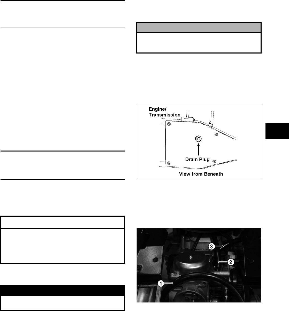
3-11
3
Table of Contents
(400 — Manual Transmission)
Removing Engine/Transmission……….……………... 3-11
Top-Side Components……………….…………….…….. 3-14
Removing Top-Side Components …….……………... 3-14
Left-Side Components ……………………….………….. 3-18
Removing Left-Side Components ….…………….….. 3-18
Right-Side Components …………….………….……….. 3-22
Removing Right-Side Components…..……………... 3-22
Center Crankcase Components……….……………... 3-26
Separating Crankcase Halves………….……………... 3-26
Disassembling Crankcase Half ……………………….. 3-27
Servicing Components………..……………..………….. 3-29
Assembling Crankcase Half ………………..………….. 3-56
Joining Crankcase Halves……………….………….….. 3-58
Installing Right-Side Components…….……………... 3-59
Installing Left-Side Components ………….………….. 3-62
Installing Top-Side Components ………………….….. 3-66
Installing Engine/Transmission…………….………….. 3-72
Removing Engine/
Transmission
Many service procedures can be performed without
removing the engine/transmission from the frame.
Closely observe the note introducing each sub-section
for this important information.
Secure the ATV on a support stand to elevate the
wheels.
1. Remove the seat.
2. Remove the negative cable from the battery; then
remove the positive cable. Remove the battery
vent hose; then remove the battery.
3. Remove the front and rear racks (see Section 8).
4. Remove the storage compartment and the steering
post access panel (see Section 8).
5. Drain the oil from beneath the engine/
transmission.
ATV-0109
6. Remove the front and rear fender panels (see
Section 8).
7. Disconnect the fuel hose (1), carburetor vent hose
(2), and the fuel pump vacuum hose (3) from the
carburetor.
CF178A
8. Disconnect the crankcase vent hose from the air
cleaner housing. Remove the clamp securing the
air intake hose to the carburetor; then remove the
housing.
NOTE: The air cleaner intake duct must be
removed prior to removing the air cleaner housing.
9. Remove the exhaust springs at the juncture in front
of the muffler; then slide the muffler rearward off
the mounting lugs.
AT THIS POINT
If the technician’s objective is to service/replace
left-side cover oil seals (3), front output joint oil
seal (1), rear output joint oil seal (1), and/or the oil
strainer (from beneath the engine/ transmission),
the engine/transmission does not have to be
removed from the frame.
! WARNING
Make sure the ATV is solidly supported on the
support stand to avoid injury.
! CAUTION
Battery acid is harmful if it contacts eyes, skin, or
clothing. Care must be taken whenever handling a
battery.
FOR ARCTIC CAT ATV DISCOUNT PARTS CALL 606-678-9623 OR 606-561-4983
www.mymowerparts.com
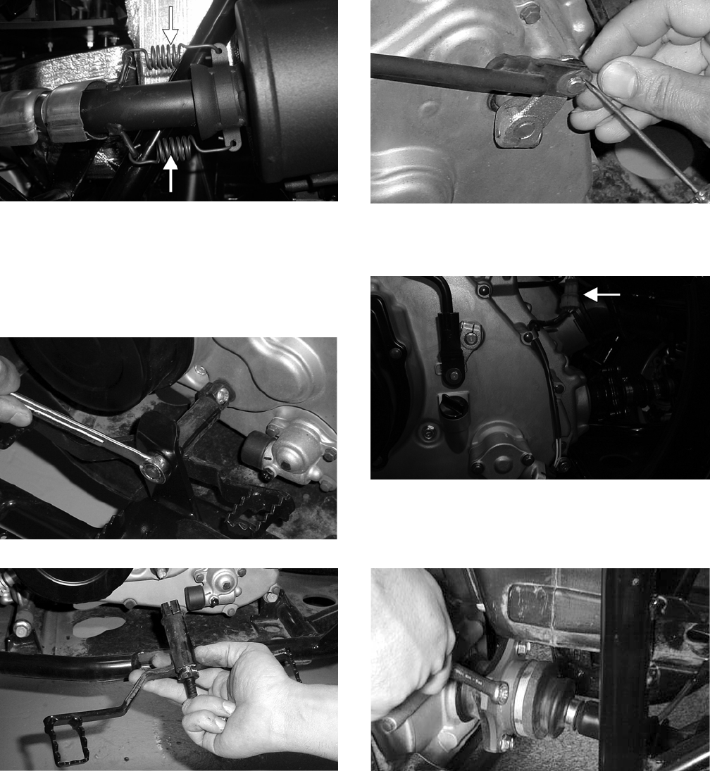
3-12
CF138A
10. Remove the exhaust pipe and account for the
exhaust seal.
11. Remove the pinch screw and lock nut securing the
gear shift lever; then remove the gear shift lever
from the shaft on the engine.
CD003
CC934
12. Remove the E-clip securing the reverse/high/low
shift linkage; then remove the linkage. Account for
the bushing and washer.
CC935
13. Disconnect the speed sensor lead from the wiring
harness.
CF172A
14. Remove the four cap screws securing the rear
output joint to the transmission and push the shaft
rearward as far as possible.
CC119D
15. Detach the carburetor from the intake boot; then
secure the carburetor assembly away from the
engine.
FOR ARCTIC CAT ATV DISCOUNT PARTS CALL 606-678-9623 OR 606-561-4983
www.mymowerparts.com
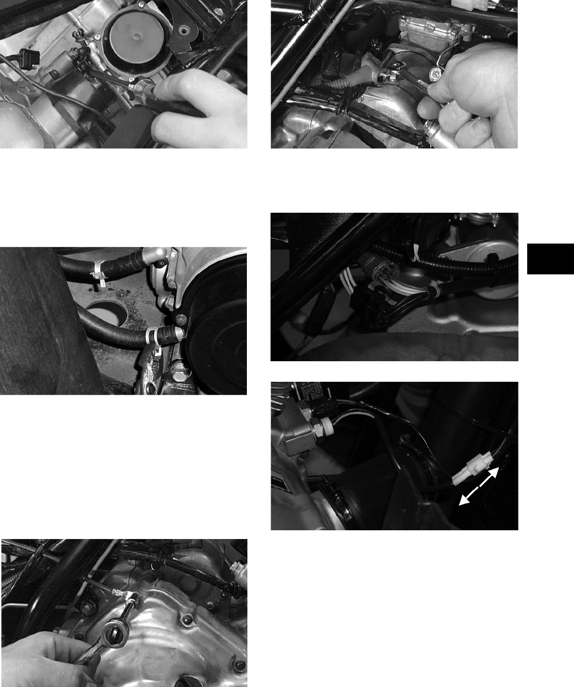
3-13
3
CC120D
NOTE: Use cable ties or tape to secure the car-
buretor assembly above the handlebar to keep it
from interfering with the removal procedure.
16. Remove the clamps securing the two oil cooler
hoses to the engine; then disconnect the hoses.
CC937
NOTE: After disconnecting the oil cooler hoses,
plug them to prevent leakage from the cooler.
17. Disconnect the high tension lead from the spark
plug. At the ignition coil, remove the cap screw,
nut, and the two wire leads; then remove the coil.
18. Disconnect the battery ground (negative) cable
from the crankcase cover; then disconnect the
positive cable from the starter motor.
AR600D
AR604D
19. Disconnect the following electrical components:
voltage regulator, CDI, indicator lights, and the
two wire leads for the oil temperature sensors.
CF165
CF164A
20. Loosen the clamp on the crankcase breather vent
hose; then disconnect the hose and remove it.
21. Remove the engine/transmission mounting
fasteners in the following sequence:
A. Lower front: One cap screw, nut, spacer, and
washer.
FOR ARCTIC CAT ATV DISCOUNT PARTS CALL 606-678-9623 OR 606-561-4983
www.mymowerparts.com
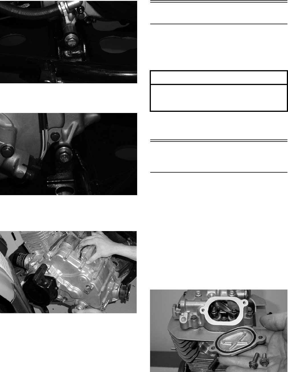
3-14
CF175
B. Lower rear: One cap screw and nut with flat
washer.
CF176
22. By sliding the rear of the engine out first, remove
the engine/transmission from the left side of the
frame.
CC940
Top-Side Components
NOTE: For efficiency, it is preferable to remove
and disassemble only those components which
need to be addressed and to service only those
components. The technician should use discretion
and sound judgment.
NOTE: The engine/transmission does not have
to removed from the frame for this procedure.
Removing Top-Side
Components
A. Valve Cover
B. Cylinder Head
NOTE: Remove the spark plug and timing
inspection plug; then using the recoil starter,
rotate the crankshaft to top-dead-center of the
compression stroke.
NOTE: Arctic Cat recommends the use of new
gaskets, lock nuts, and seals and lubricating all
internal components when servicing the
engine/transmission.
1. Remove the cap screws securing the two tappet
covers. Remove the two tappet covers. Account
for the O-rings.
MD1264
NOTE: Keep the mounting hardware with the
covers for assembly purposes or thread them back
into the head to keep them separated.
AT THIS POINT
To service any one specific component, only
limited disassembly of components may be
necessary. Note the AT THIS POINT information in
each sub-section.
FOR ARCTIC CAT ATV DISCOUNT PARTS CALL 606-678-9623 OR 606-561-4983
www.mymowerparts.com
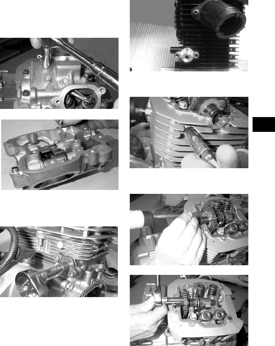
3-15
3
2. Remove the 12 cap screws securing the valve
cover to the head; account for the four rubber
washers on the top side cap screws. Remove the
valve cover. Account for and note the orientation
of the cylinder head plug; then remove the plug.
Note the location of two alignment pins.
MD1261
MD1354A
3. Loosen the cap screw on the end of the cam chain
tensioner; then remove the two Allen-head cap
screws securing the tensioner assembly and
remove the assembly. Account for a gasket.
MD1245
CD382
4. Remove the cam chain tensioner pivot cap screw
and washer.
MD1251
5. Bend the washer tabs and remove the two cap
screw securing the sprocket to the camshaft.
MD1136
MD1137
FOR ARCTIC CAT ATV DISCOUNT PARTS CALL 606-678-9623 OR 606-561-4983
www.mymowerparts.com
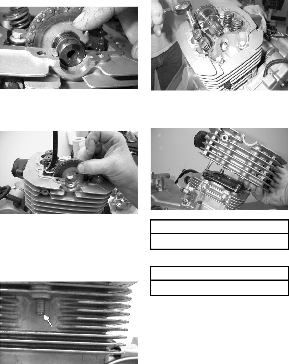
3-16
6. Using an awl, rotate the C-ring in its groove until
it is out of the cylinder head; then remove the
C-ring.
NOTE: Care should be taken not to drop the
C-ring down into the crankcase.
MD1131
7. Note the timing marks for installing purposes; then
drop the sprocket off the camshaft. While holding
the chain, slide the sprocket and camshaft out of
the cylinder head. Account for an alignment pin.
MD1132
NOTE: Loop the chain over the cylinder and
secure it with a wire to keep it from falling into the
crankcase.
8. Remove the cam chain tensioner by lifting it from
the chain cavity; then remove the two lower nuts
securing the cylinder head to the cylinder, one in
front and one in rear.
MC1192
9. Remove the four cylinder head cap screws and
washers. Note that the two cap screws on the right
side of the cylinder head nearest the cam sprocket
are longer than the two cap screws on the left
(spark plug) side.
MD1167
10. Remove the cylinder head from the cylinder,
remove the gasket, and account for two alignment
pins.
MD1163
11. Remove the cam chain guide.
AT THIS POINT
To service valves and cylinder head, see
Servicing Top-Side Components sub-section.
AT THIS POINT
To inspect cam chain guide, see Servicing
Top-Side Components sub-section.
FOR ARCTIC CAT ATV DISCOUNT PARTS CALL 606-678-9623 OR 606-561-4983
www.mymowerparts.com
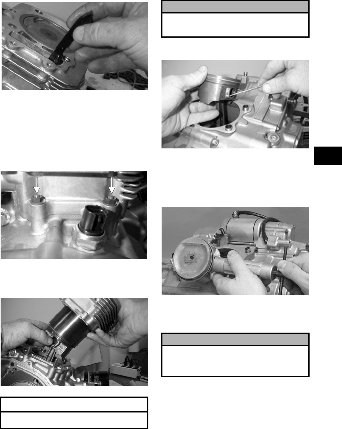
3-17
3
MD1173
C. Cylinder
D. Piston
NOTE: Steps 1-11 in the preceding sub-section
must precede this procedure.
12. Remove the two nuts securing the right side of the
cylinder to the right-side crankcase half. Account
for the washers.
MD1226A
13. Lift the cylinder off the crankcase taking care not
to allow the piston to drop against the crankcase.
Account for the gasket and two alignment pins.
MD1214
14. Using an awl, remove one piston-pin circlip. Take
care not to drop it into the crankcase.
MD1213
15. Using the Piston Pin Puller (p/n 0644-328),
remove the piston pin. Account for the
opposite-side circlip. Remove the piston.
NOTE: It is advisable to remove the oppo-
site-side circlip prior to using the puller.
MD1219
NOTE: Support the connecting rod with rubber
bands to avoid damaging the rod or install the
Connecting Rod Holder (p/n 0444-006).
NOTE: If the existing rings will not be replaced
with new rings, note the location of each ring for
proper installation. When replacing with new rings,
replace as a complete set only. If the piston rings
must be removed, remove them in this sequence.
A. Starting with the top ring, slide one end of the
ring out of the ring-groove.
AT THIS POINT
To service cylinder, see Servicing Top-Side
Components sub-section.
! CAUTION
When removing the cylinder, be sure to support the
piston to prevent damage to the crankcase and pis-
ton.
! CAUTION
Do not allow the connecting rod to go down inside
the crankcase. If the rod is down inside the crank-
case and the crankshaft is rotated, severe damage
will result.
FOR ARCTIC CAT ATV DISCOUNT PARTS CALL 606-678-9623 OR 606-561-4983
www.mymowerparts.com
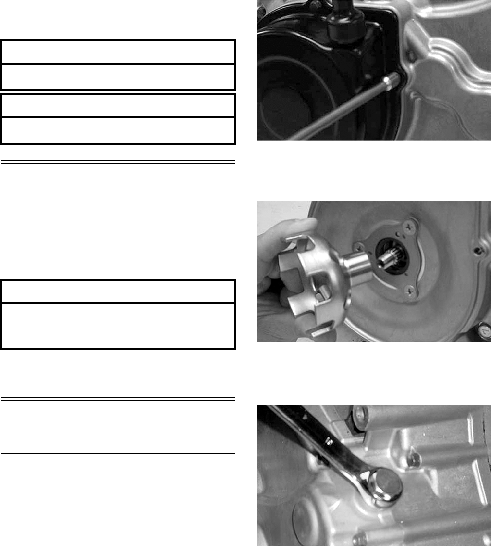
3-18
B. Remove each ring by working it toward the
dome of the piston while rotating it out of the
groove.
Left-Side Components
NOTE: For efficiency, it is preferable to remove
and disassemble only those components which
need to be addressed and to service only those
components. The technician should use discretion
and sound judgment.
NOTE: The engine/transmission does not have
to be removed from the frame for this procedure.
Removing Left-Side
Components
A. Cover/Stator Assembly
1. Remove the two cap screws securing the starter to
the crankcase; then remove the starter.
2. Remove the four cap screws securing the recoil
cover to the left-side cover; then remove recoil
cover.
CC942
3. Remove the flange nut securing the starter cup to
the crankshaft; then remove the starter cup.
Account for the O-ring inside the cup.
CC943
4. Remove the gear shift stopper (located above the
hi/low shift shaft). Account for the washer, spring,
and stopper.
CC944
NOTE: Remove the two cap screws securing the
speed sensor housing; then remove the housing.
Account for the gasket.
AT THIS POINT
To service piston, see Servicing Top-Side
Components sub-section.
AT THIS POINT
To service center crankcase components only,
proceed to Removing Left-Side Components.
AT THIS POINT
To service any one specific component, only
limited disassembly of components may be
necessary. Note the AT THIS POINT information in
each sub-section.
FOR ARCTIC CAT ATV DISCOUNT PARTS CALL 606-678-9623 OR 606-561-4983
www.mymowerparts.com
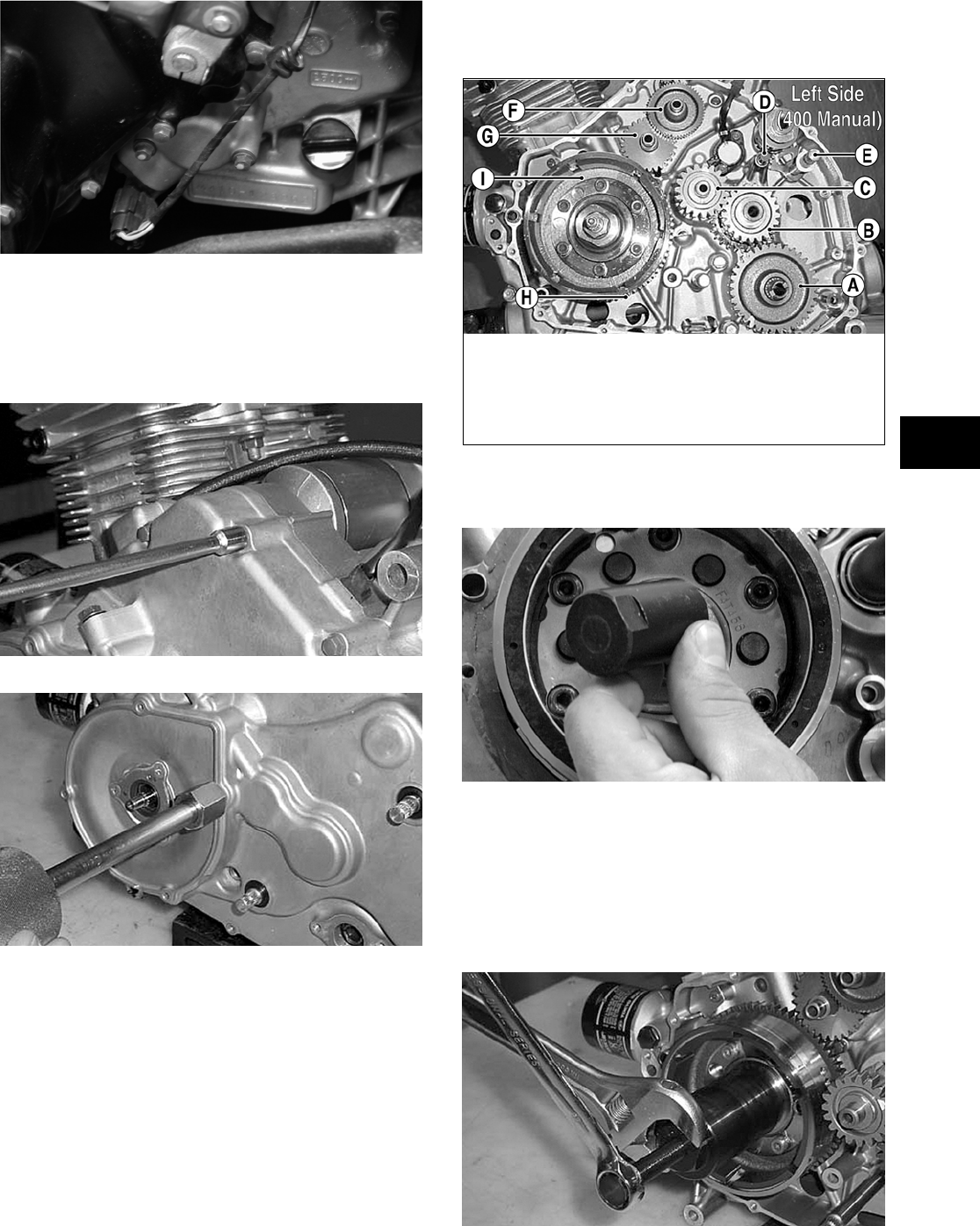
3-19
3
CF109
5. Remove the cap screws securing the left-side
cover to the crankcase (fifteen 6 mm and one 8
mm); then using an appropriate slide hammer and
Slide Hammer 6 mm Adapter (p/n 0644-310),
remove the left-side cover.
CC945
CC946
NOTE: Inspect the inside of the left-side cover
for any shaft washers and spacers that may have
come off with the cover. Make sure they are
returned to their respective shafts. Also, make
sure the alignment pins are in place.
B. Rotor/Flywheel
C. Idle Gear Assembly
NOTE: Steps 1-5 in the preceding sub-section
must precede this procedure.
NOTE: For steps 6-14, refer to illustration
CC948B.
NOTE: To aid in installing, it is recommended
that the assemblies are kept together and IN
ORDER.
CC948B
6. Remove the nut securing the rotor/flywheel (I) to
the crankshaft; then install the crankshaft protector.
CC514D
7. Using the Magneto Rotor Remover (p/n 0444-075),
remove the rotor/flywheel assembly from the
crankshaft. Account for the key; then remove the
starter clutch gear assembly (H) w/washer.
NOTE: Care must be taken that the remover is
threaded all the way onto the rotor/flywheel.
CC949
KEY
A. Driven Gear
B. Drive Gears #1 & #2
C. Idler Gear
D. Shift Fork with Pin
E. Shift Shaft
F. Starter Idler Gear #1
G. Starter Idler Gear #2
H. Starter Clutch Gear
Assembly
I. Rotor/Flywheel
FOR ARCTIC CAT ATV DISCOUNT PARTS CALL 606-678-9623 OR 606-561-4983
www.mymowerparts.com
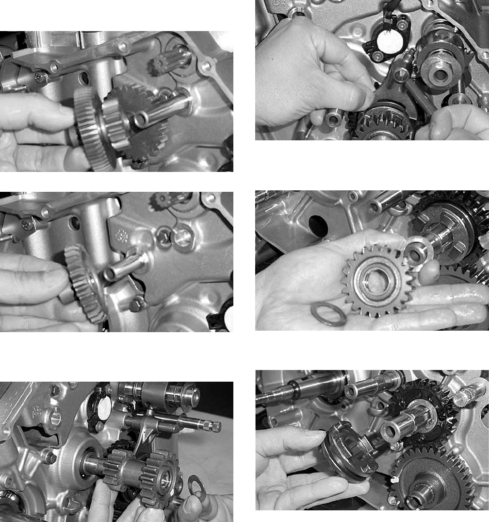
3-20
8. Remove the starter idler gears (F & G) from the
crankcase; then remove the pin.
CC950
CC951
9. Remove the idler gear (C). Account for a washer
and a spacer.
CC952
10. Remove the shift fork and pin (D).
CC953
11. Remove drive gear #2 (B). Account for washers on
both sides of the gear.
CC954
12. Remove the sliding dog from the driveshaft.
CC966
13. Remove the circlip, washer, and drive gear #1 (B)
from the driveshaft; then account for the bushing
and the spacer.
FOR ARCTIC CAT ATV DISCOUNT PARTS CALL 606-678-9623 OR 606-561-4983
www.mymowerparts.com
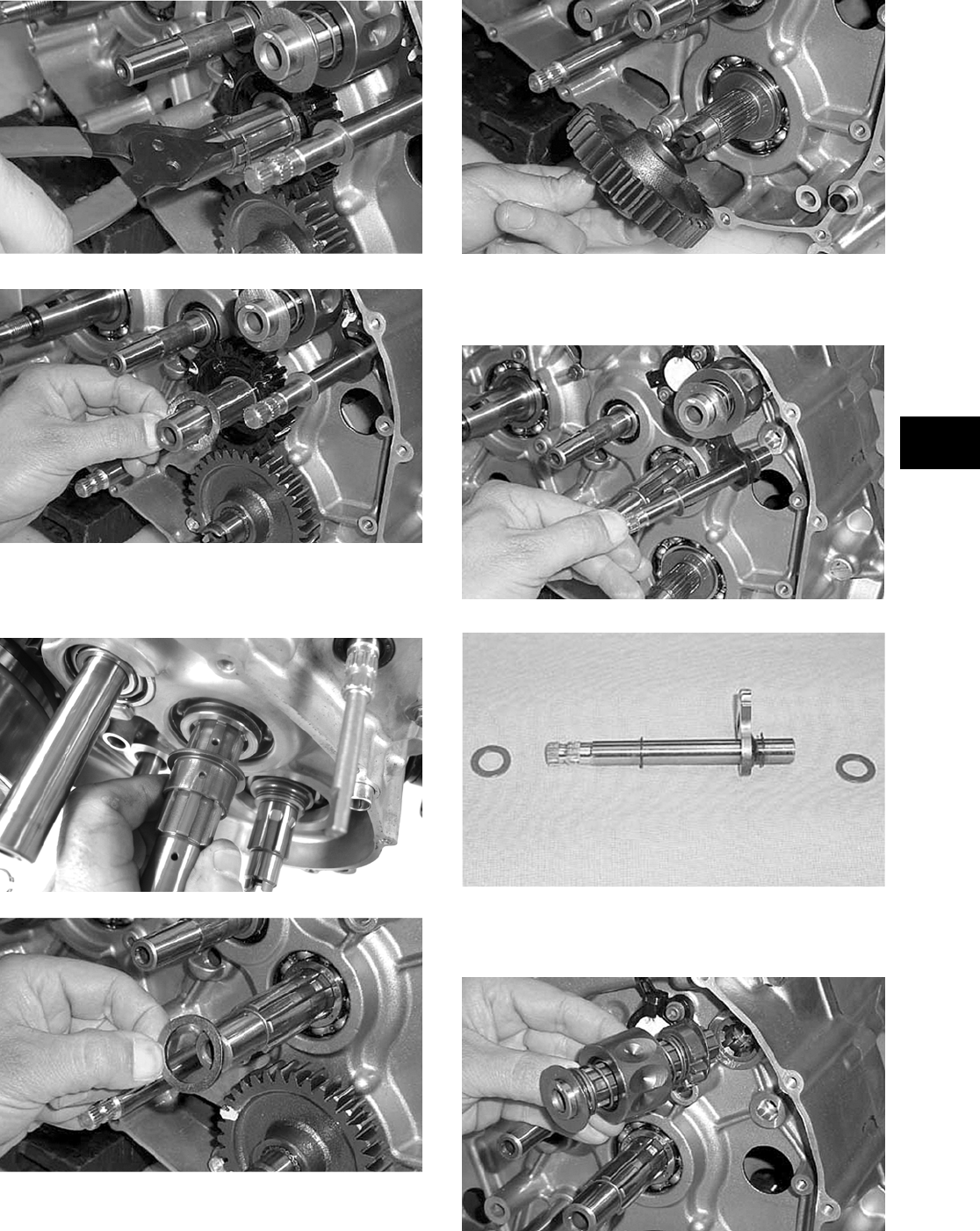
3-21
3
CC955
CC956
NOTE: Note the orientation of the oil holes on
the driveshaft and bushing for installing purposes.
CD552
CC958
14. Remove driven gear (A) from the output shaft.
CC959
15. Remove the gear shift shaft. Account for two
shims.
CC960
CC961
16. Remove the secondary stopper camshaft assembly.
Account for the two shims.
CC962
FOR ARCTIC CAT ATV DISCOUNT PARTS CALL 606-678-9623 OR 606-561-4983
www.mymowerparts.com
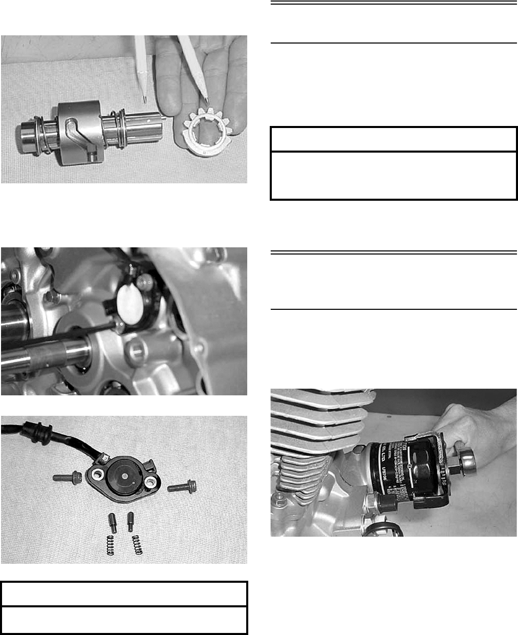
3-22
NOTE: Note the alignment dots on the cam plate
and camshaft for installing purposes.
CC963
17. Remove the Allen-head cap screws from the
neutral switch base; then remove the switch.
Account for the two contacts and springs.
CC964
CC965
Right-Side Components
NOTE: For efficiency, it is preferable to remove
and disassemble only those components which
need to be addressed and to service only those
components. The technician should use discretion
and sound judgment.
NOTE: The engine/transmission does not have
to be removed from the frame for this procedure.
Removing Right-Side
Components
A. Oil Filter
1. Using an adjustable Oil Filter Wrench (p/n
0644-389), remove the oil filter.
CC967
2. If the engine has not been removed, lay the ATV
on its left side; then remove the cap screws
securing the right-side cover to the crankcase.
Remove the cover. Account for the gasket and for
two alignment pins.
AT THIS POINT
To service center crankcase components only,
proceed to Removing Right-Side Components.
AT THIS POINT
To service any one specific component, only
limited disassembly of components may be
necessary. Note the AT THIS POINT information in
each sub-section.
FOR ARCTIC CAT ATV DISCOUNT PARTS CALL 606-678-9623 OR 606-561-4983
www.mymowerparts.com
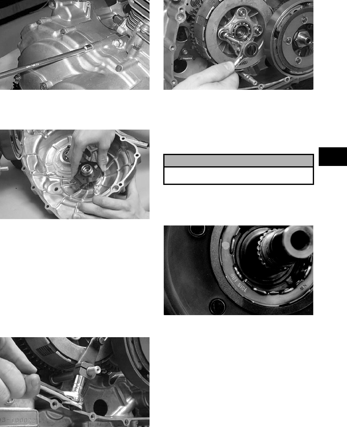
3-23
3
CC968
NOTE: When removing the right-side cover,
account for the release roller guide that it does not
fall and cause damage.
CC070D
B. Primary Clutch Shoe
C. Primary Clutch
D. Centrifugal Clutch Housing
NOTE: Steps 1-2 in the preceding sub-section
must precede this procedure.
3. Remove the cap screw securing the clutch release
arm and remove the arm; then in a crisscross
pattern, remove the four cap screws securing the
clutch release roller assembly.
NOTE: Scribe a reference mark with a marker on
the arm and shaft to aid in installing.
CC073D
CC074D
4. Remove the release roller assembly. Account for
four springs.
5. Remove the centrifugal clutch-shoe nut (left-hand
threads) and washer from the driveshaft; then
using a primary clutch shoe remover, remove the
clutch shoe.
6. Remove the primary drive one-way clutch from
the centrifugal clutch housing. Note the word
OUTSIDE stamped on the clutch for assembly
purposes.
CF043
7. Using the Clutch Sleeve Hub Holder (p/n
0444-007) to hold the clutch sleeve hub, remove
the nut and washer.
! CAUTION
Care must be taken when removing the nut; it has
“left-hand” threads.
FOR ARCTIC CAT ATV DISCOUNT PARTS CALL 606-678-9623 OR 606-561-4983
www.mymowerparts.com
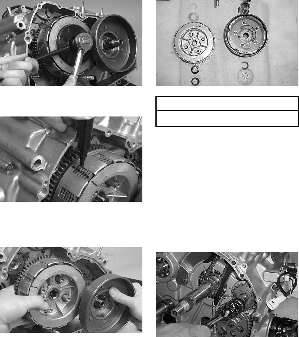
3-24
CC076D
8. Scribe a line across the primary clutch assembly to
aid in installing.
CC077D
9. Simultaneously, remove the primary clutch
assembly and centrifugal clutch housing from
their respective shafts. Account for the shims
and washers.
CC078D
CC969
E. Gear Shift Cam Plate/Guide
F. Oil Pump/Oil Strainer
NOTE: Steps 1-9 in the preceding sub-sections
must precede this procedure.
NOTE: Note that the bushings on the crankshaft
are directional and that the oil holes align for
installing purposes.
10. Remove the nut and washer securing the oil pump
drive gear to the crank balancer shaft; then remove
the gear and account for the pin, gear, washer, and
nut.
NOTE: Note that the raised hub of the gear is
directed inward for installing purposes.
CC971
AT THIS POINT
To service clutch components, see Servicing
Right-Side Components sub-section.
FOR ARCTIC CAT ATV DISCOUNT PARTS CALL 606-678-9623 OR 606-561-4983
www.mymowerparts.com
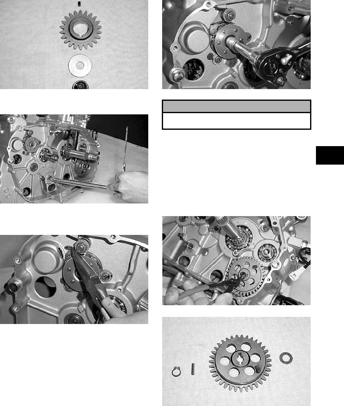
3-25
3
CC972
11. Remove the gear shift shaft from the crankcase.
CC973
12. Release the tension from the gear shift cam
stopper arm spring.
CC974
13. Remove the cap screw securing the gear shift cam
plate and guide to the gear shift cam; then remove
the cam plate and guide. Account for the guide and
five pins.
CC975
NOTE: For general servicing, it is advisable to
disassemble, clean, and inspect the oil pump. If
any wear or damage is suspected, replace the oil
pump.
14. Remove the circlip securing the oil pump driven
gear; then remove the gear. Account for the pin
and the washer.
NOTE: Always use a new circlip when installing
the oil pump driven gear.
CC976
CC977
15. Remove the three Phillips-head screws securing
the oil pump; then remove the oil pump.
! CAUTION
If servicing of the engine/transmission is due to a
lubrication-related problem, replace the oil pump.
FOR ARCTIC CAT ATV DISCOUNT PARTS CALL 606-678-9623 OR 606-561-4983
www.mymowerparts.com
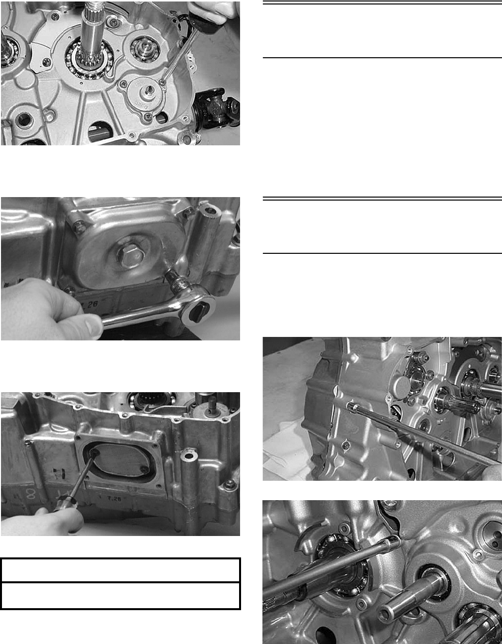
3-26
CC978
16. Remove the cap screws securing the oil strainer
cap; then remove the cap. Account for the O-ring.
CC091D
17. Remove the two Phillips-head cap screws securing
the strainer.
CC163D
Center Crankcase
Components
NOTE: This procedure cannot be done with the
engine/transmission in the frame. Complete
Removing procedures for Top-Side, Left-Side, and
Right-Side must precede this procedure.
NOTE: For efficiency, it is preferable to remove
and disassemble only those components which
need to be addressed and to service only those
components. The technician should use discretion
and sound judgment.
Separating Crankcase
Halves
1. Remove the five right-side 6 mm cap screws (one
from inside the case) securing the crankcase
halves; then remove the seven left-side 6 mm cap
screws. Note the location of the different-lengthed
cap screws and a wiring form.
CC979
CC980
2. Remove the four left-side 8 mm cap screws (two
from inside the case) securing the crankcase
halves. Note the location of the different-lengthed
cap screws.
AT THIS POINT
To service center crankcase components only,
proceed to Separating Crankcase Halves.
FOR ARCTIC CAT ATV DISCOUNT PARTS CALL 606-678-9623 OR 606-561-4983
www.mymowerparts.com
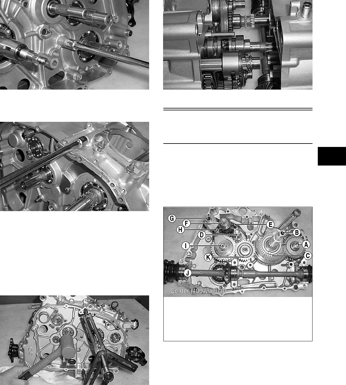
3-27
3
CC981
3. Remove the four right-side 8 mm cap screws
securing the crankcase halves.
CC982
4. Using an appropriate crankcase separator and
tapping lightly with a rubber mallet, separate the
crankcase halves. Account for two alignment
pins, a C-ring, and two washers.
NOTE: To keep the shaft/gear assemblies intact
for identification, tap the shafts toward the
left-side crankcase half when separating the
halves.
CC983
CC984
Disassembling
Crankcase Half
NOTE: For steps 1-10, refer to illustration
CC985B.
NOTE: To aid in assembling, it is recommended
that the assemblies are kept together and IN
ORDER.
CC985B
1. Remove the output shaft assembly (J).
2. Remove the two shift shafts (E and H).
3. Remove the reverse shift cam (G) and spacer.
4. Disengage four forks from the gear shift cam
(F); then remove the reverse shifter fork.
KEY
A. Crank Balancer Assembly
B. Crankshaft
C. Balancer Drive Gear with
Pin
D. Countershaft Assembly
E. Shift Shaft with Fork
F. Gear Shift Cam
G. Reverse Shift Cam
H. Shift Shaft with 3 Forks
I. Driveshaft Assembly
J. Output Shaft Assembly
K. Reverse Idle Gear
FOR ARCTIC CAT ATV DISCOUNT PARTS CALL 606-678-9623 OR 606-561-4983
www.mymowerparts.com
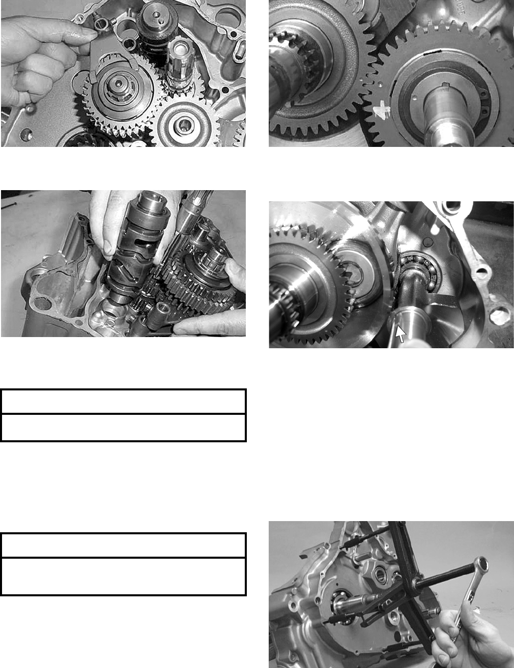
3-28
CC986
5. Remove the gear shift cam (F).
CC987
6. Remove the three remaining forks noting their
positions for assembling purposes.
7. Remove the reverse idle gear (K) w/shaft.
Account for the bushing, two washers, and the
circlip.
8. Simultaneously, remove the driveshaft assembly
(I) and countershaft assembly (D).
NOTE: For efficiency, if the driveshaft and/or
countershaft are not being serviced, it is prefera-
ble to leave them assembled. The technician
should use discretion and sound judgment.
NOTE: Note the alignment marks on the crank
balancer driven gear and balancer drive gear to aid
in assembly.
CC166D
9. Remove the driven gear from the crank balancer
assembly (A). Account for a key.
CD832A
NOTE: Note that the shoulder of the gear is
directed to the outside for assembling purposes.
10. Remove the crank balancer assembly (A).
NOTE: When removing the crank balancer
assembly, rotate the crankshaft counterweight
away from the crank balancer assembly counter-
weight.
11. Using an appropriate crankshaft remover, push
the crankshaft assembly out of the crankcase.
CC115D
AT THIS POINT
To service gear shift forks, see Servicing Center
Crankcase Components sub-section.
AT THIS POINT
To service the driveshaft and/or countershaft, see
Servicing Center Crankcase Components
sub-section.
FOR ARCTIC CAT ATV DISCOUNT PARTS CALL 606-678-9623 OR 606-561-4983
www.mymowerparts.com
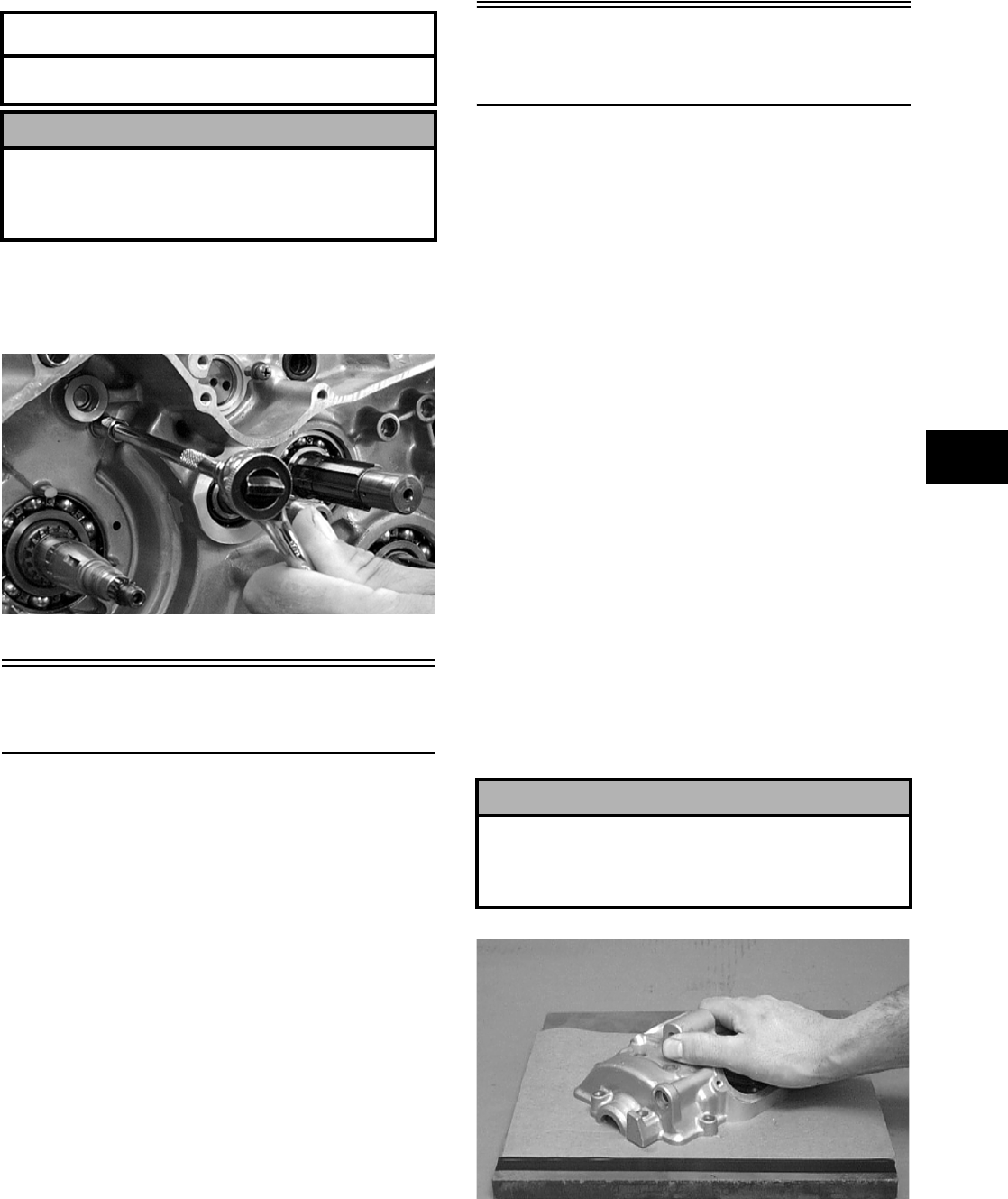
3-29
3
12. To remove the output shaft and gear, remove the
nut, slide the gear off the shaft (account for a
shim or shims), and drive the shaft out with a
plastic mallet (account for a shim or shims).
CC482D
Table of Contents
(Servicing Components)
NOTE: Critical engine/transmission specifica—
tions are located at the beginning of this section.
Servicing Top-Side Components ……..……………... 3-29
Valve Assembly ………………….…………….……….. 3-29
Piston Assembly ……….…………….…………….….. 3-32
Cylinder/Cylinder Head Assembly ………………… 3-34
Servicing Left-Side Components .…………….…….. 3-37
Recoil Starter ………………………….…………….….. 3-37
Measuring Shift Fork (Thickness) ………….…….. 3-40
Measuring Shift Fork Groove (Width) …………… 3-41
Measuring Shift Fork To Groove
(Side Clearance) ……….………….…………….…….. 3-41
Servicing Right-Side Components ………………….. 3-41
Primary Clutch Assembly…………..………….…….. 3-41
Inspecting Oil Pump ..…………….…………….…….. 3-44
Servicing Center Crankcase Components ……….. 3-44
Secondary Gears ………………….………….……….. 3-44
Crankshaft Assembly ……………….…………….….. 3-46
Driveshaft…………….………………………..………….. 3-47
Countershaft …………..…………….…………….…….. 3-53
Servicing Top-Side
Components
NOTE: Whenever a part is worn excessively,
cracked, or damaged in any way, replacement is
necessary.
VALVE ASSEMBLY
When servicing valve assembly, inspect valve seats,
valve stems, valve faces, and valve stem ends for
pits, burn marks, or other signs of abnormal wear.
NOTE: Whenever a valve is out of tolerance, it
must be replaced.
Cleaning/Inspecting Valve Cover
NOTE: If the valve cover cannot be trued, the cyl-
inder head assembly must be replaced.
1. Wash the valve cover in parts-cleaning solvent.
2. Place the valve cover on the Surface Plate (p/n
0644-016) covered with #400 grit wet-or-dry
sandpaper. Using light pressure, move the valve
cover in a figure eight motion. Inspect the seal-
ing surface for any indication of high spots. A
high spot can be noted by a bright metallic fin-
ish. Correct any high spots before assembly by
continuing to move the valve cover in a figure
eight motion until a uniform bright metallic fin-
ish is attained.
CC130D
AT THIS POINT
To service crankshaft assembly, see Servicing
Center Crankcase Components sub-section.
! CAUTION
Do not remove the remaining output shaft assembly
unless absolutely necessary. If the shaft is removed,
the shaft nut must be replaced with a new one and
the shaft must be re-shimmed.
! CAUTION
Do not remove an excessive amount of the sealing
surface or damage to the camshaft will result.
Always check camshaft clearance when resurfacing
the valve cover.
FOR ARCTIC CAT ATV DISCOUNT PARTS CALL 606-678-9623 OR 606-561-4983
www.mymowerparts.com
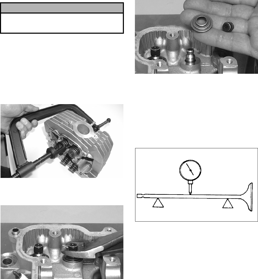
3-30
Removing Valves
NOTE: Keep all valves and valve components as
a set. Note the original location of each valve set
for use during installation. Return each valve set to
its original location during installation.
1. Using a valve spring compressor, compress the
valve springs and remove the valve cotters.
Account for an upper spring retainer.
CC994
2. Remove the valve seal and the lower remaining
spring seat. Discard the valve seal.
CC134D
CC136D
NOTE: The valve seals must be replaced.
3. Remove the valve springs; then invert the cylin-
der head and remove the valves.
Measuring Valve Stem Runout
1. Support each valve stem end with the V Blocks
(p/n 0644-022); then check the valve stem
runout using a dial indicator.
ATV-1082
2. Maximum runout must not exceed specifica-
tions.
Measuring Valve Stem
Outside Diameter
1. Using a micrometer, measure the valve stem
outside diameter.
2. Acceptable diameter range (intake valve) must
be within specifications.
3. Acceptable diameter range (exhaust valve) must
be within specifications.
Measuring Valve Face/Seat Width
1. Using a micrometer, measure the width of the
valve face.
! CAUTION
Water or parts-cleaning solvent must be used in
conjunction with the wet-or-dry sandpaper or dam-
age to the sealing surface may result.
FOR ARCTIC CAT ATV DISCOUNT PARTS CALL 606-678-9623 OR 606-561-4983
www.mymowerparts.com
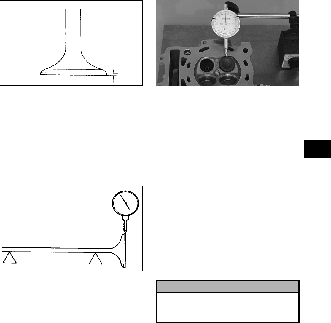
3-31
3
ATV-1004
2. Acceptable width range must be within specifi-
cations.
Measuring Valve Face Radial
Runout
1. Mount a dial indicator on the surface plate; then
place the valve stem on a set of V blocks.
2. Position the dial indicator contact point on the
outside edge of the valve face; then zero the
indicator.
ATV1082A
3. Rotate the valve in the V blocks.
4. Maximum runout must not exceed specifica-
tions.
Measuring Valve Guide/Valve Stem
Deflection (Wobble Method)
1. Mount a dial indicator and base on the surface
plate; then place the cylinder head on the surface
plate.
2. Install the valve into the cylinder head; then
position the dial indicator contact point against
the outside edge of the valve face. Zero the indi-
cator.
CC131D
3. Push the valve from side to side; then from top
to bottom.
4. Maximum “wobble” deflection must not exceed
specifications.
Measuring Valve Guide
(Inside Diameter)
1. Insert a snap gauge 1/2 way down into each
valve guide bore; then remove the gauge and
measure it with a micrometer.
2. Acceptable inside diameter range must be
within specifications.
3. If a valve guide is out of tolerance, it must be
replaced.
Servicing Valves/Valve
Guides/Valve Seats
If valves, valve guides, or valve seats require servic-
ing or replacement, Arctic Cat recommends that the
components be taken to a qualified machine shop
for servicing.
Measuring Rocker Arm
(Inside Diameter)
1. Using a dial calipers, measure the inside diame-
ter of the rocker arm.
2. Acceptable inside diameter range must be
within specifications.
Measuring Rocker Arm Shaft
(Outside Diameter)
1. Using a micrometer, measure the outside diame-
ter of the rocker arm shaft.
! CAUTION
If any valve is discolored or pitted or if the seating
surface is worn, the valve must be replaced. Do not
attempt to grind a valve or severe engine damage
may occur.
FOR ARCTIC CAT ATV DISCOUNT PARTS CALL 606-678-9623 OR 606-561-4983
www.mymowerparts.com
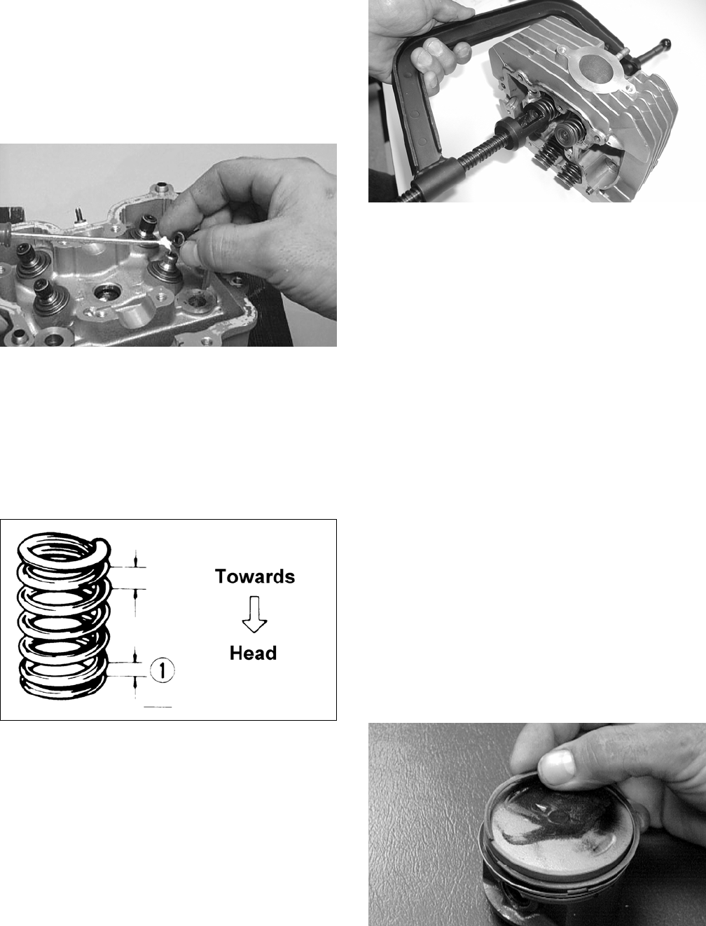
3-32
2. Acceptable outside diameter range must be
within specifications.
Installing Valves
1. Apply grease to the inside surface of the valve
seals; then place a lower spring seat and valve
guide seal over each valve guide.
CC144D
2. Insert each valve into its original valve location.
3. Install the valve springs with the painted end of
the spring facing away from the cylinder head.
NOTE: If the paint is not visible, install the ends
of the springs with the closest wound coils toward
the head.
ATV-1011A
4. Place a spring retainer over the valve springs;
then using the valve spring compressor, com-
press the valve springs and install the valve cot-
ters.
CC994
PISTON ASSEMBLY
NOTE: Whenever a piston, rings, or pin are out
of tolerance, they must be replaced.
Cleaning/Inspecting Piston
1. Using a non-metallic carbon removal tool,
remove any carbon buildup from the dome of
the piston.
2. Inspect the piston for cracks in the piston pin,
dome, and skirt areas.
3. Inspect the piston for seizure marks or scuffing.
Repair with #400 grit wet-or-dry sandpaper and
water or honing oil.
NOTE: If scuffing or seizure marks are too deep
to correct with the sandpaper, replace the piston.
4. Inspect the perimeter of each piston for signs of
excessive “blowby.” Excessive “blowby” indi-
cates worn piston rings or an out-of-round cylin-
der.
Removing Piston Rings
1. Starting with the top ring, slide one end of the
ring out of the ring-groove.
CC400D
2. Remove each ring by working it toward the
dome of the piston while rotating it out of the
groove.
FOR ARCTIC CAT ATV DISCOUNT PARTS CALL 606-678-9623 OR 606-561-4983
www.mymowerparts.com
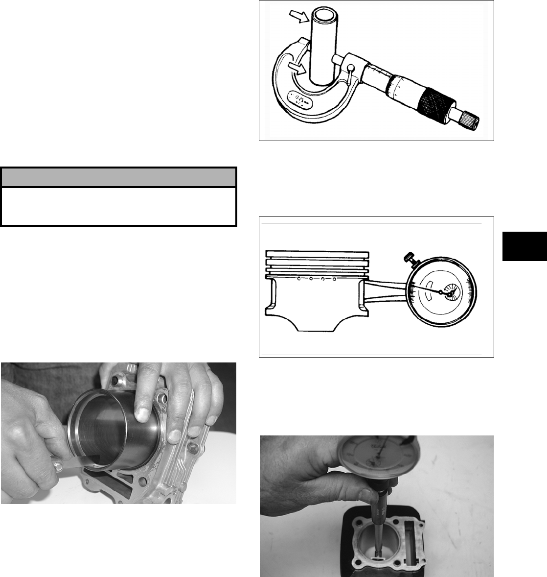
3-33
3
NOTE: If the existing rings will not be replaced
with new ones, note the location of each ring for
proper installation. When installing new rings,
install as a complete set only.
Cleaning/Inspecting Piston Rings
1. Take an old piston ring and snap it into two
pieces; then grind the end of the old ring to a 45°
angle and to a sharp edge.
2. Using the sharpened ring as a tool, clean carbon
from the ring-grooves. Be sure to position the
ring with its tapered side up.
Measuring Piston-Ring End Gap
(Installed)
1. Place each piston ring in the wear portion of the
cylinder. Use the piston to position each ring
squarely in the cylinder.
2. Using a feeler gauge, measure each piston-ring
end gap. Acceptable ring end gap must be
within specifications.
CC995
Measuring Piston Pin (Outside
Diameter) and Piston-Pin Bore
1. Measure the piston pin outside diameter at each
end and in the center. If measurement is not
within specifications, the piston pin must be
replaced.
ATV-1070
2. Insert an inside dial indicator into the piston-pin
bore. The diameter must not exceed specifica-
tions. Take two measurements to ensure accu-
racy.
ATV-1069
Measuring Piston Skirt/
Cylinder Clearance
1. Measure the cylinder front to back in six places.
CD325
2. Measure the corresponding piston diameter at a
point 15 mm (0.6 in.) above the piston skirt at a
right angle to the piston-pin bore. Subtract this
measurement from the measurement in step 1.
The difference (clearance) must be within speci-
fications.
! CAUTION
Improper cleaning of the ring-grooves by the use of
the wrong type of ring-groove cleaner will result in
severe damage to the piston.
FOR ARCTIC CAT ATV DISCOUNT PARTS CALL 606-678-9623 OR 606-561-4983
www.mymowerparts.com
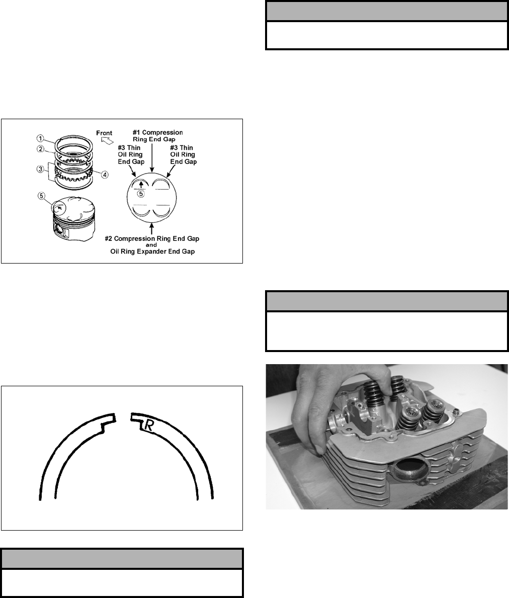
3-34
Installing Piston Rings
1. Install ring expander (4) in the bottom groove of
the piston; then install the thin oil rings (3) over
the expander making sure the expander ends do
not overlap. Stagger the end gaps of the upper
and lower thin oil rings according to the illustra-
tion.
NOTE: Note the direction of the exhaust side of
the piston (5) for correct ring end gap orientation.
ATV-1085B
2. Install the compression rings (1 and 2) so the let-
ter on the top surface of each ring faces the
dome of the piston. Rotate the rings until the
ring end gaps are on directly opposite sides of
the piston (see illustration).
NOTE: The chrome (silver) ring should be
installed in the top position.
726-306A
CYLINDER/CYLINDER HEAD
ASSEMBLY
NOTE: If the cylinder/cylinder head assembly
cannot be trued, they must be replaced.
Cleaning/Inspecting Cylinder Head
1. Using a non-metallic carbon removal tool,
remove any carbon buildup from the combus-
tion chamber being careful not to nick, scrape,
or damage the combustion chamber or the seal-
ing surface.
2. Inspect the spark plug hole for any damaged
threads. Repair damaged threads using a
“heli-coil” insert.
3. Place the cylinder head on the surface plate cov-
ered with #400 grit wet-or-dry sandpaper. Using
light pressure, move the cylinder head in a fig-
ure eight motion. Inspect the sealing surface for
any indication of high spots. A high spot can be
noted by a bright metallic finish. Correct any
high spots before assembly by continuing to
move the cylinder head in a figure eight motion
until a uniform bright metallic finish is attained.
CC996
Measuring Cylinder Head
Distortion
1. Remove any carbon buildup in the combustion
chamber.
2. Lay a straightedge across the cylinder head; then
using a feeler gauge, check the distortion factor
between the head and the straightedge.
3. Maximum distortion must not exceed specifica-
tions.
! CAUTION
Incorrect installation of the piston rings will result in
engine damage.
! CAUTION
The cylinder head studs must be removed for this
procedure.
! CAUTION
Water or parts-cleaning solvent must be used in
conjunction with the wet-or-dry sandpaper or dam-
age to the sealing surface may result.
FOR ARCTIC CAT ATV DISCOUNT PARTS CALL 606-678-9623 OR 606-561-4983
www.mymowerparts.com
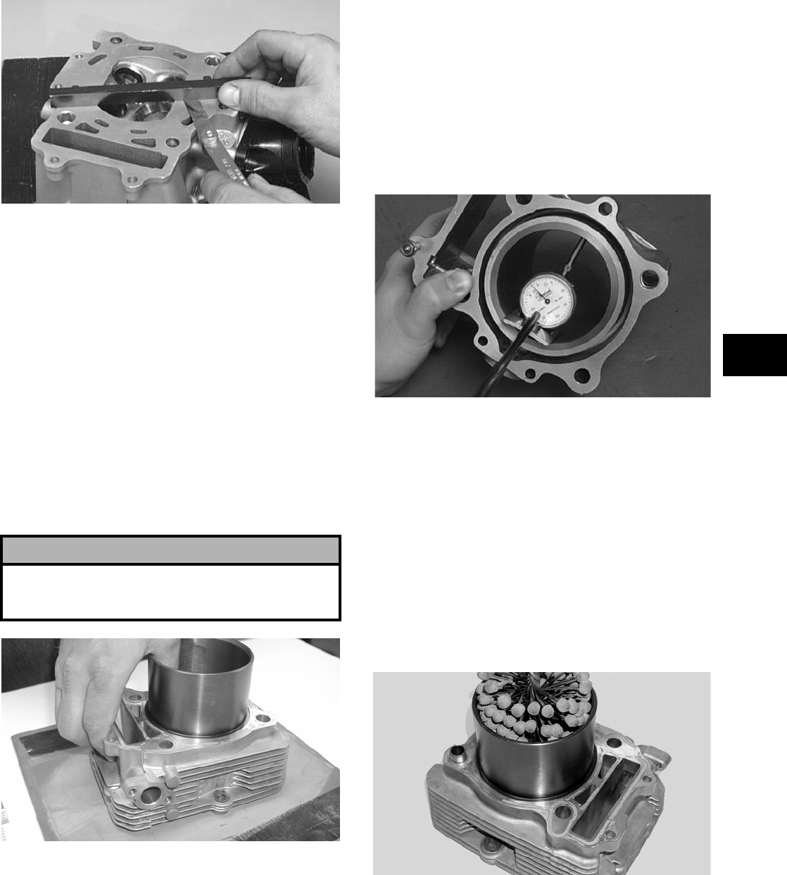
3-35
3
CC141D
Cleaning/Inspecting Cylinder
1. Wash the cylinder in parts-cleaning solvent.
2. Inspect the cylinder for pitting, scoring, scuff-
ing, warpage, and corrosion. If marks are found,
repair the surface using a cylinder hone (see
Honing Cylinder in this sub-section).
3. Place the cylinder on the surface plate covered
with #400 grit wet-or-dry sandpaper. Using light
pressure, move the cylinder in a figure eight
motion. Inspect the sealing surface for any indi-
cation of high spots. A high spot can be noted by
a bright metallic finish. Correct any high spots
before assembly by continuing to move the cyl-
inder in a figure eight motion until a uniform
bright metallic finish is attained.
CC997
Inspecting Cam Chain Guide
1. Inspect cam chain guide for cuts, tears, breaks,
or chips.
2. If the chain guide is damaged, it must be
replaced.
Honing Cylinder
1. Using a slide gauge and a dial indicator or a
snap gauge, measure the cylinder bore diameter
in three locations from top to bottom and again
from top to bottom at 90° from the first mea-
surements for a total of six measurements. The
trueness (out-of-roundness) is the difference
between the highest and lowest reading. Maxi-
mum trueness (out-of-roundness) must not
exceed specifications.
CC127D
2. Wash the cylinder in parts-cleaning solvent.
3. Inspect the cylinder for pitting, scoring, scuff-
ing, and corrosion. If marks are found, repair the
surface using a ball hone.
NOTE: To produce the proper 60° cross-hatch
pattern, use a low RPM drill (600 RPM) at the rate
of 30 strokes per minute. If honing oil is not avail-
able, use a lightweight petroleum-based oil. Thor-
oughly clean cylinder after honing using soap and
hot water. Dry with compressed air; then immedi-
ately apply oil to the cylinder bore. If the bore is
severely damaged or gouged, replace the cylinder.
CC998
4. If any measurement exceeds the limit, bore the
cylinder and install an oversized piston or replace
the cylinder.
NOTE: Oversized piston and rings are available
in 0.50 mm (0.020 in.) only.
! CAUTION
Water or parts-cleaning solvent must be used in
conjunction with the wet-or-dry sandpaper or dam-
age to the sealing surface may result.
FOR ARCTIC CAT ATV DISCOUNT PARTS CALL 606-678-9623 OR 606-561-4983
www.mymowerparts.com
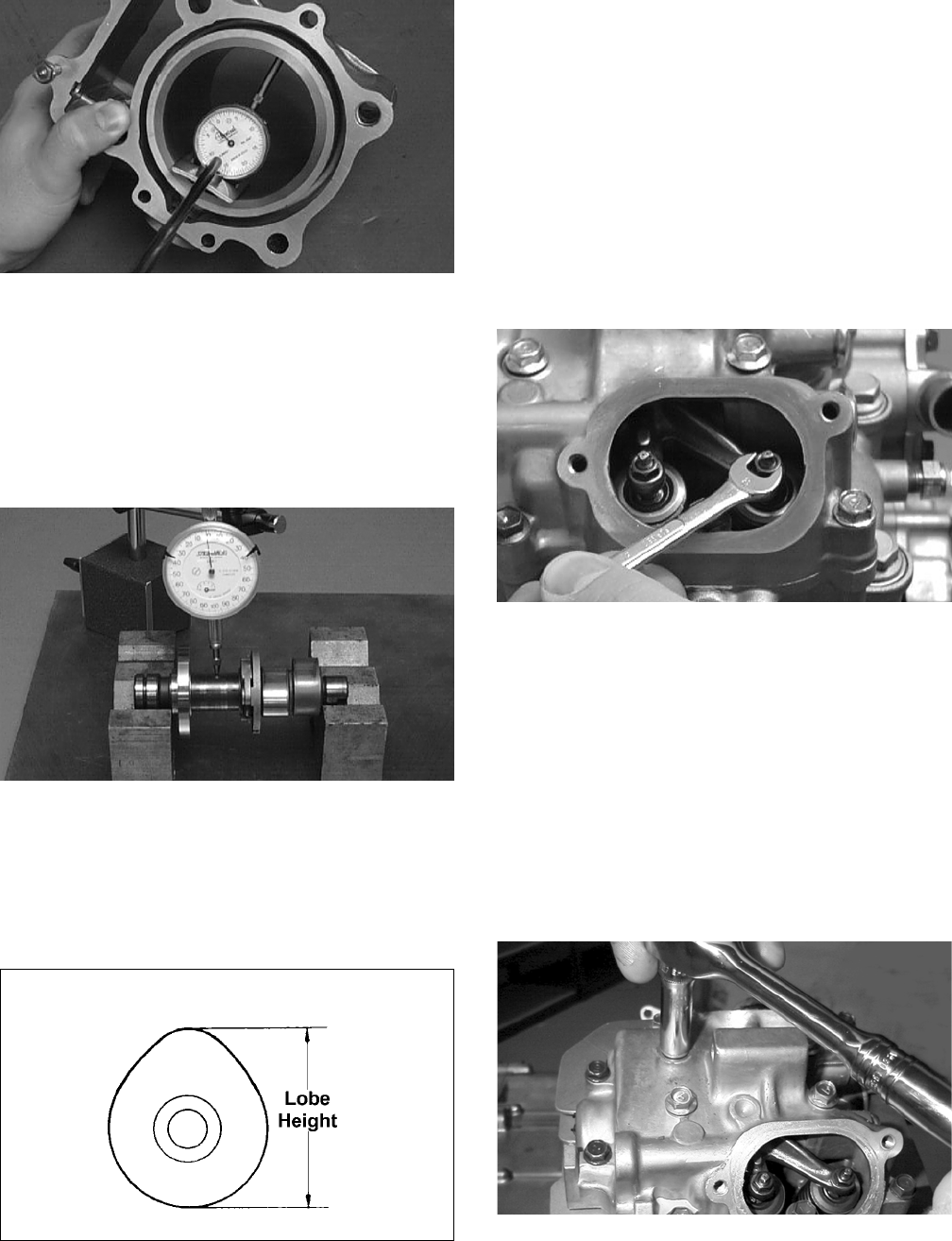
3-36
CC127D
Measuring Camshaft Runout
NOTE: If the camshaft is out of tolerance, it must
be replaced.
1. Place the camshaft on a set of V blocks; then
position the dial indicator contact point against
the shaft and zero the indicator.
CC283D
2. Rotate the camshaft and note runout; maximum
tolerance must not exceed specifications.
Measuring Camshaft Lobe Height
1. Using a calipers, measure each cam lobe height.
ATV1013A
2. The lobe heights must not exceed minimum
specifications.
Inspecting Camshaft Bearing
Journal
1. Inspect the bearing journal for scoring, seizure
marks, or pitting.
2. If excessive scoring, seizure marks, or pitting is
found, the cylinder head assembly must be
replaced.
Measuring Camshaft to
Cylinder Head Clearance
1. Remove the adjuster screws and jam nuts.
CC005D
2. Place a strip of plasti-gauge in each of the cam-
shaft lands in the cylinder head.
3. Place the valve cover on the cylinder head and
secure with the valve cover cap screws. Tighten
securely.
NOTE: Do not rotate the camshaft when measur-
ing clearance.
4. Remove the cap screws securing the valve cover
to the cylinder; then remove the valve cover and
camshaft.
MD1261
5. Match the width of the plasti-gauge with the
chart found on the plasti-gauge packaging to
determine camshaft to cylinder head and valve
cover clearance.
FOR ARCTIC CAT ATV DISCOUNT PARTS CALL 606-678-9623 OR 606-561-4983
www.mymowerparts.com
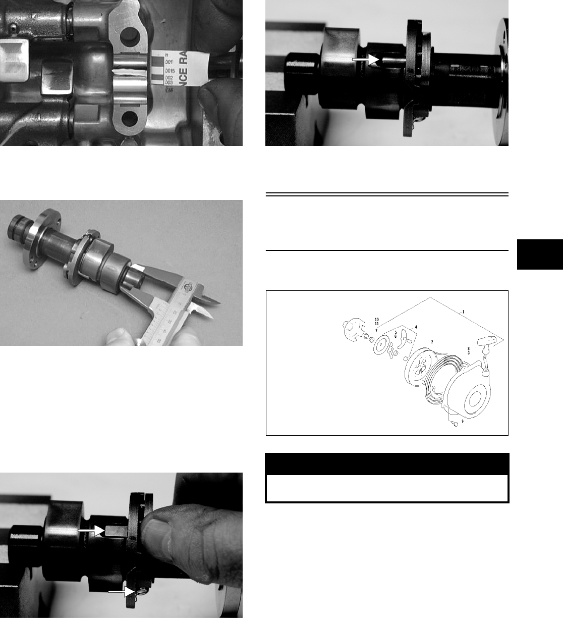
3-37
3
CC145D
6. If clearance is excessive, measure the journals of
the camshaft.
CC287D
NOTE: If the journals are worn, replace the cam-
shaft; then measure the clearance again. If it is still
out of tolerance, replace the cylinder head.
Inspecting Camshaft Spring/Drive
Pin
1. Inspect the spring and drive pin for damage.
CF061A
CF060A
2. If damaged, the camshaft must be replaced.
Servicing Left-Side
Components
RECOIL STARTER
0737-034
Removing/Disassembling
1. Remove the cap screws securing the recoil
starter assembly to the left-side cover; then
remove the starter.
! WARNING
Always wear safety glasses when servicing the
recoil starter.
KEY
1. Recoil Starter
Assy
2. Reel
3. Spiral Spring
4. Ratchet Assy
5. Ratchet
6. Ratchet Guide
7. Nut
8. Rope Assy
9. Cap Screw
10. Starter Cup
11. Nut
FOR ARCTIC CAT ATV DISCOUNT PARTS CALL 606-678-9623 OR 606-561-4983
www.mymowerparts.com
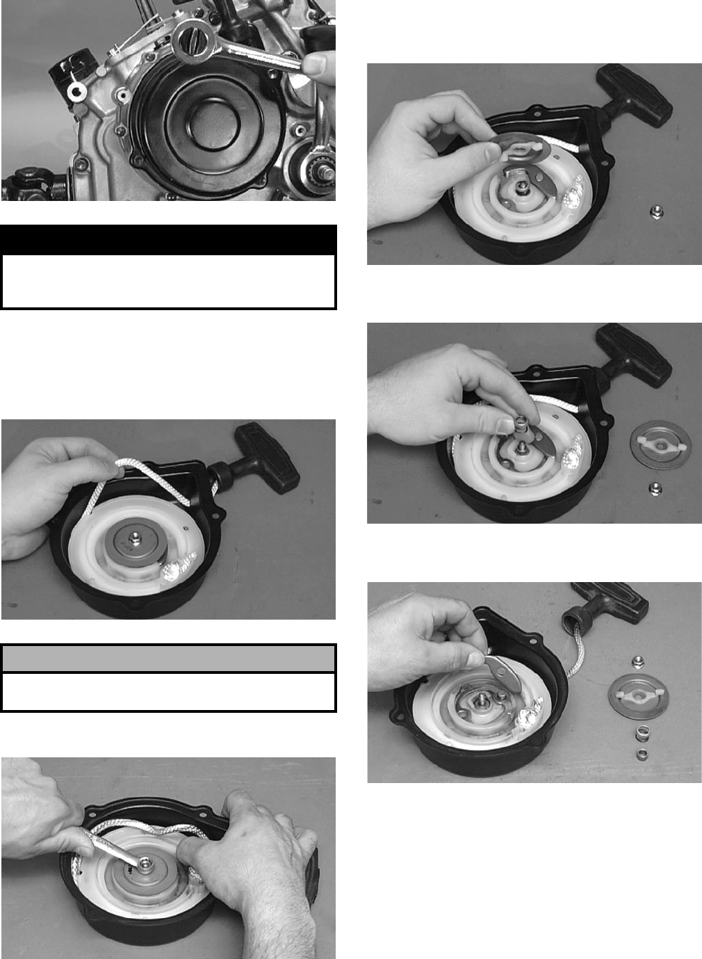
3-38
CC039D
2. Rotate the reel counterclockwise until the notch
of the reel is near the rope guide in the case.
Guide the rope into the notch and slowly allow
the reel to retract until all spiral spring tension is
released.
B600D
3. Remove the nut.
B601D
4. Slowly release the friction plate and lift the plate
with ratchet guide free of the recoil case; then
remove the ratchet guide from the friction plate.
B602D
5. Remove the spring cover, spring, and shaft.
B603D
6. Remove the ratchet and account for the pin.
B604D
7. Carefully lift the reel free of the case making
sure the spiral spring does not accidentally dis-
engage from the case.
! WARNING
During the disassembly procedure, continuous
downward pressure must be exerted on the reel so it
does not accidentally disengage and cause injury.
! CAUTION
During the disassembly procedure, make sure all
spring tension is released before continuing.
FOR ARCTIC CAT ATV DISCOUNT PARTS CALL 606-678-9623 OR 606-561-4983
www.mymowerparts.com
3-39
3
B605D
8. Remove the protective cover from the starter
handle and pull the rope out of the handle; then
untie the knot in the rope and remove the han-
dle.
NOTE: Do not remove the spiral spring unless
replacement is necessary. It should be visually
inspected in place to save time. If replacement is
necessary, follow steps 9-10.
9. Remove the spiral spring from the case by lift-
ing the spring end up and out. Hold the remain-
der of the spring with thumbs and alternately
release each thumb to allow the spring to gradu-
ally release from the case.
10. Unwind the rope from the reel and remove the
rope.
Cleaning and Inspecting
NOTE: Whenever a part is worn excessively,
cracked, or damaged in any way, replacement is
necessary.
1. Clean all components.
2. Inspect the springs and ratchet for wear or dam-
age.
3. Inspect the reel and case for cracks or damage.
4. Inspect the shaft for wear, cracks, or damage.
5. Inspect the rope for breaks or fraying.
6. Inspect the spiral spring for cracks, crystalliza-
tion, or abnormal bends.
7. Inspect the handle for damage, cracks, or deteri-
oration.
Assembling/Installing
1. If removed, insert the spiral spring into the case
with the outer end of the spring around the
mounting lug in the case; then wind it in a coun-
terclockwise direction until the complete spring
is installed.
NOTE: The spiral spring must seat evenly in the
recoil case.
B606D
2. Insert the rope through the hole in the reel and
tie a knot in the end; then wrap the rope counter-
clockwise around the reel leaving approximately
50 cm (20 in.) of rope free of the reel.
3. Apply low-temperature grease to the spring and
hub.
4. Thread the end of the rope through the guide
hole of the case; then thread the rope through the
handle and secure it with a double knot. Install
the protective cover into the handle.
5. Align the inner hook of the spiral spring with the
notch in the reel.
B605D
6. Install the ratchet onto its pin making sure the
end is properly installed on the reel.
! WARNING
Care must be taken when lifting the reel free of the
case. Wear safety glasses to avoid injury.
FOR ARCTIC CAT ATV DISCOUNT PARTS CALL 606-678-9623 OR 606-561-4983
www.mymowerparts.com
3-40
B604D
7. Install the shaft, spring, and the spring cover.
B603D
8. Install the friction plate with the ratchet guide
fitting into the ratchet.
B602D
9. While pushing down on the reel, install the nut.
Tighten securely.
B601D
10. With the 50 cm (20 in.) of rope exposed, hook
the rope in the notch of the reel.
11. Rotate the reel four turns counterclockwise; then
release the rope from the notch and allow the
rope to retract.
12. Pull the rope out two or three times to check for
correct tension.
NOTE: Increasing the rotations in step 11 will
increase spring tension.
13. Place the recoil starter assembly into position on
the left-side cover; then tighten the cap screws
to specifications.
CC039D
MEASURING SHIFT FORK
(Thickness)
NOTE: Whenever a shift fork is out of tolerance,
replacement is necessary.
1. Using a calipers, in turn measure the thickness
of the machined tip of each shift fork.
FOR ARCTIC CAT ATV DISCOUNT PARTS CALL 606-678-9623 OR 606-561-4983
www.mymowerparts.com
3-41
3
CC296D
2. Shift fork thickness must be within specifica-
tions.
MEASURING SHIFT FORK GROOVE
(Width)
1. Using a calipers, in turn measure the width of
each shift fork groove.
CC288D
2. Shift fork groove width must be within specifi-
cations.
MEASURING SHIFT FORK TO
GROOVE (Side Clearance)
1. In turn, insert each shift fork into its groove.
2. Using a feeler gauge, measure the clearance
between the shift fork and the groove.
CC292D
3. Shift fork to groove side clearance must be
within specifications.
Servicing Right-Side
Components
NOTE: Whenever a part is worn excessively,
cracked, damaged in any way, or out of tolerance,
replacement is necessary.
PRIMARY CLUTCH ASSEMBLY
(Inspecting/Measuring/
Assembling)
NOTE: Prior to inspecting and measuring com-
ponents, it is recommended that all components
be removed from the primary gear assembly and
be cleaned.
NOTE: When removing components from the pri-
mary gear assembly, account for the bushing that
fits into the primary gear.
CC239D
Inspecting/Measuring Clutch
Driven Plate Warpage
1. Inspect each driven plate for warpage and burn
marks.
2. In turn place each driven plate on the surface
plate; then using a feeler gauge, measure
warpage in several locations.
FOR ARCTIC CAT ATV DISCOUNT PARTS CALL 606-678-9623 OR 606-561-4983
www.mymowerparts.com
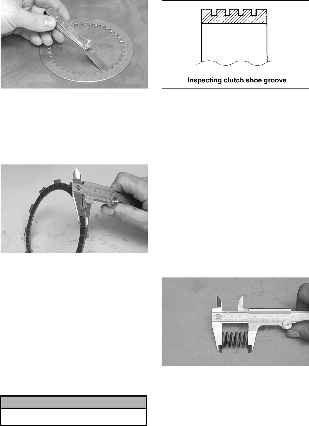
3-42
CC245D
3. Maximum driven plate warpage must not
exceed specifications.
Measuring Clutch Drive Plate
(Fiber) Thickness
1. Using a calipers, in turn measure the thickness
of each drive plate in several locations.
CC243D
2. Drive plate thickness must not exceed minimum
specifications.
3. If the fiber plate tabs are damaged, the plate
must be replaced.
4. Inspect the clutch sleeve hub for grooves or
notches. If grooves or notches are present,
replace the hub.
Inspecting Centrifugal Clutch Shoe
1. Inspect the clutch shoe for uneven wear, chips,
cracks, or discoloration.
2. Inspect the depth of the grooves in the clutch
shoes. If any shoe is worn to the bottom of the
groove, replace the complete set.
ATV1014
Inspecting Centrifugal Clutch
Housing
1. Inspect the clutch housing for burns, marks,
scuffs, cracks, scratches, or uneven wear.
2. If the housing is damaged in any way, the hous-
ing must be replaced.
Inspecting Primary
One-Way Drive
1. Insert the drive into the clutch housing.
2. Rotate the inner race by hand and verify the
inner race rotates only one direction.
3. If the inner race is locked in place or rotates both
directions, the drive assembly must be replaced.
Measuring Clutch Spring Length
1. Using a calipers, measure the overall free length
of the clutch spring.
CC247D
2. Overall length must not exceed minimum speci-
fications.
! CAUTION
Always replace clutch shoes as a complete set or
severe imbalance could occur.
FOR ARCTIC CAT ATV DISCOUNT PARTS CALL 606-678-9623 OR 606-561-4983
www.mymowerparts.com
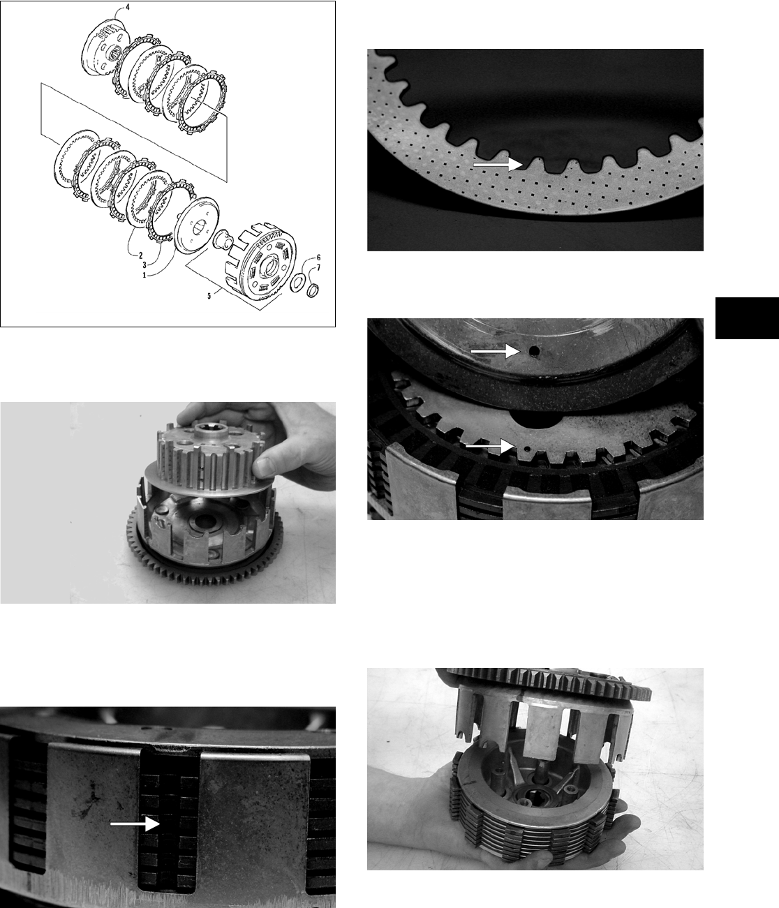
3-43
3
Assembling Primary Clutch
737-731A
1. Place the clutch hub upside down into the pri-
mary gear assembly.
CC920
2. Alternately install the drive plates and driven
plates onto the hub (starting and ending with a
drive plate) making sure the tabs with the
notches are all in line with each other.
CF044A
NOTE: When installing the driven plates for ease
of installation, make sure they are placed onto the
hub with the rounded side of the plates directed
down.
CF045A
3. Install the pressure plate onto the hub making
sure the alignment dots are correctly positioned.
CF047A
4. Place the primary gear assembly w/clutch hub
assembly in one hand, place the other hand on
top of the clutch hub assembly, and flip the
assembly over; then lift the primary gear assem-
bly off the clutch hub assembly being careful
not to disturb the drive plate notched tab orienta-
tion.
CC924
5. Place the primary gear assembly on a clean, flat
surface; then install the primary washer into the
assembly.
KEY
1. Pressure Disc
2. Driven Plate
3. Drive Plate
4. Sleeve Hub
5. Primary Gear Assy
6. Washer
7. Washer
FOR ARCTIC CAT ATV DISCOUNT PARTS CALL 606-678-9623 OR 606-561-4983
www.mymowerparts.com
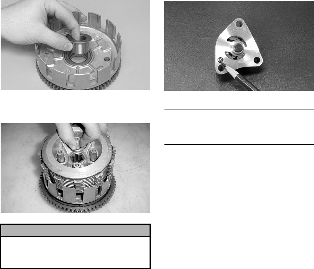
3-44
CC239D
6. Place the clutch hub assembly into the primary
gear assembly.
CC926
NOTE: The primary clutch assembly is now com-
pletely assembled for installation.
INSPECTING OIL PUMP
1. Inspect the pump for damage.
2. It is inadvisable to remove the screw securing
the pump halves. If the oil pump is damaged, it
must be replaced.
CC446D
Servicing Center
Crankcase Components
NOTE: Whenever a part is worn excessively,
cracked, damaged in any way, or out of tolerance,
replacement is necessary.
SECONDARY GEARS
NOTE: When checking and correcting secondary
gear backlash and tooth contact, the universal
joint must be secured to the front shaft or false
measurements will occur.
Checking Backlash
NOTE: The rear shaft and bevel gear must be
removed for this procedure. Also, always start with
the original shims on the rear shaft.
1. Place the left-side crankcase cover onto the
left-side crankcase half to prevent runout of the
secondary transmission output shaft.
2. Install the secondary driven output shaft assem-
bly onto the crankcase.
3. Mount the indicator tip of the dial indicator on
the secondary driven bevel gear.
4. While rocking the driven bevel gear back and
forth, note the maximum backlash reading on
the gauge.
5. Acceptable backlash range is 0.05-0.33 mm
(0.002-0.013 in.).
Correcting Backlash
NOTE: If backlash measurement is within the
acceptable range, no correction is necessary.
! CAUTION
The clutch hub and the pressure plate must be seated
in the proper position. If any of the incorrect positions
are used, the hub and plate will have clearance
between them and they will not operate properly.
FOR ARCTIC CAT ATV DISCOUNT PARTS CALL 606-678-9623 OR 606-561-4983
www.mymowerparts.com
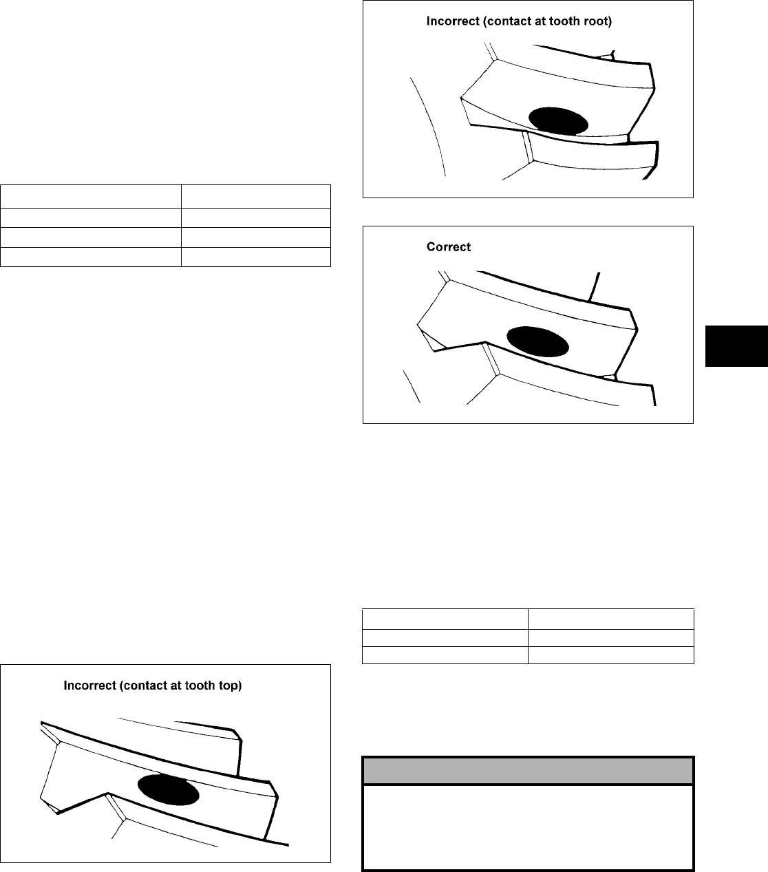
3-45
3
1. If backlash measurement is less than specified,
remove an existing shim, measure it, and install
a new thinner shim.
2. If backlash measurement is more than specified,
remove an existing shim, measure it, and install
a thicker shim.
NOTE: Continue to remove, measure, and install
until backlash measurement is within tolerance.
Note the following chart.
Checking Tooth Contact
NOTE: After correcting backlash of the second-
ary driven bevel gear, it is necessary to check
tooth contact.
1. Remove the secondary driven output shaft
assembly from the left-side crankcase half.
2. Clean the secondary driven bevel gear teeth of
old oil and grease residue.
3. Apply a thin, even coat of a machinist-layout
dye to several teeth of the gear.
4. Install the secondary driven output shaft assem-
bly.
5. Rotate the secondary driven bevel gear several
revolutions in both directions.
6. Examine the tooth contact pattern in the dye and
compare the pattern to the illustrations.
ATV-0103
ATV-0105
ATV-0104
Correcting Tooth Contact
NOTE: If tooth contact pattern is comparable to
the correct pattern illustration, no correction is
necessary.
If tooth contact pattern is comparable to an incorrect
pattern, correct tooth contact according to the fol-
lowing chart.
NOTE: To correct tooth contact, steps 1 and 2
(with NOTE) of “Correcting Backlash” must be fol-
lowed and the above “Tooth Contact/Shim Correc-
tion” chart must be consulted.
Backlash Measurement Shim Correction
Under 0.05 mm (0.002 in.) Decrease Shim Thickness
At 0.05-0.33 mm (0.002-0.013 in.) No Correction Required
Over 0.33 mm (0.013 in.) Increase Shim Thickness
Tooth Contact Shim Correction
Contacts at Top Decrease Shim Thickness
Contacts at Root Increase Shim Thickness
! CAUTION
After correcting tooth contact, backlash must again
be checked and corrected (if necessary). Continue
the correcting backlash/correcting tooth contact
procedures until they are both within tolerance val-
ues.
FOR ARCTIC CAT ATV DISCOUNT PARTS CALL 606-678-9623 OR 606-561-4983
www.mymowerparts.com
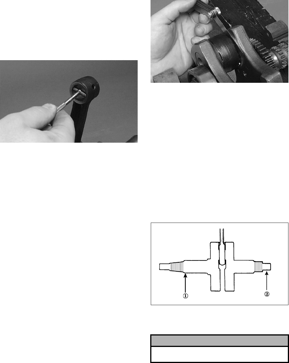
3-46
CRANKSHAFT ASSEMBLY
Measuring Connecting Rod
(Small End Inside Diameter)
1. Insert a snap gauge into the upper connecting
rod small end bore; then remove the gauge and
measure it with micrometer.
CC290D
2. Maximum diameter must not exceed specifica-
tions.
Measuring Connecting Rod
(Small End Deflection)
1. Place the crankshaft on a set of V blocks and
mount a dial indicator and base on the surface
plate. Position the indicator contact point against
the center of the connecting rod small end jour-
nal.
2. Zero the indicator and push the small end of the
connecting rod away from the dial indicator.
3. Maximum deflection must not exceed specifica-
tions.
Measuring Connecting Rod
(Big End Side-to-Side)
1. Push the lower end of the connecting rod to one
side of the crankshaft journal.
2. Using a feeler gauge, measure the gap between
the connecting rod and crankshaft journal.
CC289D
3. Acceptable gap range must be within specifica-
tions.
Measuring Connecting Rod
(Big End Width)
1. Using a calipers, measure the width of the con-
necting rod at the big-end bearing.
2. Acceptable width range must be within specifi-
cations.
Measuring Crankshaft (Runout)
1. Place the crankshaft on a set of V blocks.
2. Mount a dial indicator and base on the surface
plate. Position the indicator contact at point 1 of
the crankshaft.
ATV-1074
3. Zero the indicator and rotate the crankshaft
slowly.
4. Maximum runout must not exceed specifica-
tions.
NOTE: Proceed to check runout on the other end
of the crankshaft by positioning the indicator con-
tact at point 2 and following steps 2-4.
! CAUTION
Care should be taken to support the connecting rod
when rotating the crankshaft.
FOR ARCTIC CAT ATV DISCOUNT PARTS CALL 606-678-9623 OR 606-561-4983
www.mymowerparts.com
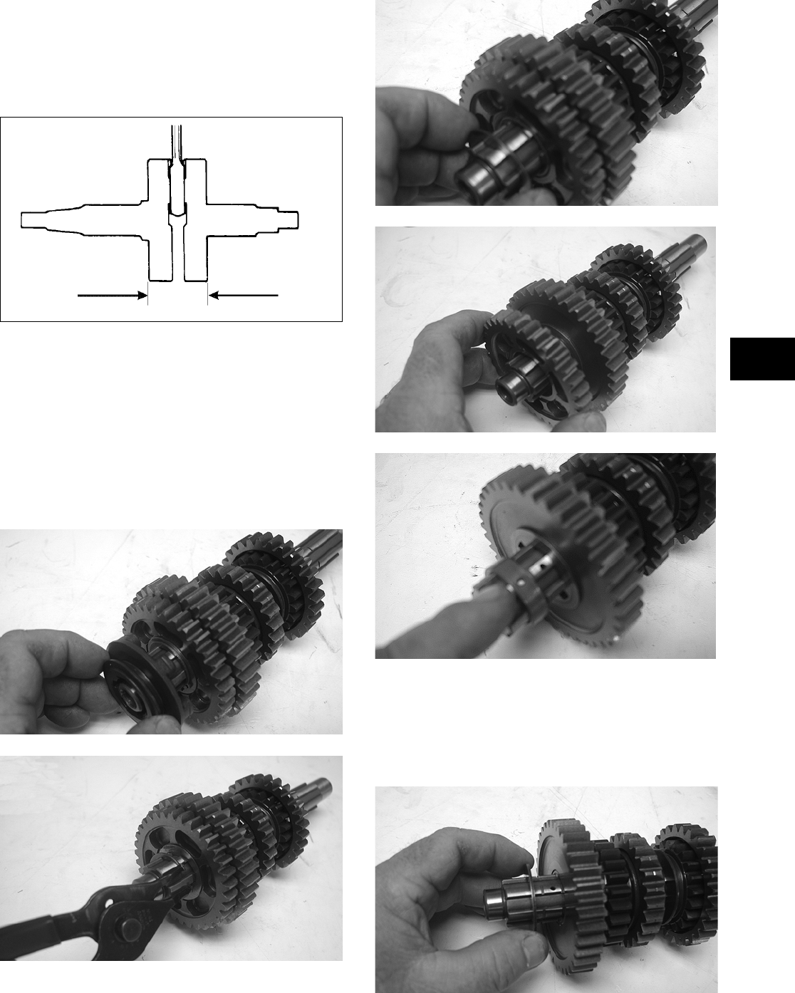
3-47
3
Measuring Crankshaft
(Web-to-Web)
1. Using a calipers, measure the distance from the
outside edge of one web to the outside edge of
the other web.
ATV-1017
2. Acceptable width range must be within specifi-
cations.
DRIVESHAFT
Disassembling
1. In order, remove the reverse dog, circlip,
washer, reverse driven gear, and bushing from
the driveshaft.
CD331
CD333
CD335
CD336
CD337
NOTE: The teeth on the bushing must face the
1st driven gear.
2. Remove the 1st driven washer (right side); then
remove the 1st driven gear from the driveshaft.
CD339
FOR ARCTIC CAT ATV DISCOUNT PARTS CALL 606-678-9623 OR 606-561-4983
www.mymowerparts.com
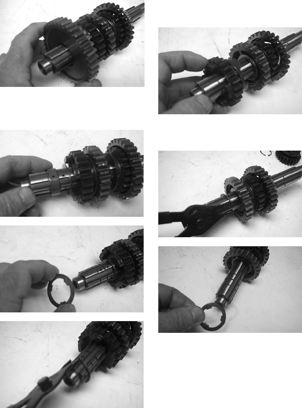
3-48
CD341
3. Remove the 1st driven bushing; then remove the
1st driven washer (left side) from the shoulder
of the splined shaft. Remove the 4th driven cir-
clip.
CD342
CD343
CD344
4. Remove the 4th driven gear from the driveshaft.
Note the four small dogs facing toward the 3rd
driven gear for assembling purposes.
CD345
5. Remove the 3rd driven circlip; then remove the
3rd driven lock washer (right side) from the
driveshaft.
CD346
CD348
6. Remove the 3rd driven gear from the driveshaft.
FOR ARCTIC CAT ATV DISCOUNT PARTS CALL 606-678-9623 OR 606-561-4983
www.mymowerparts.com
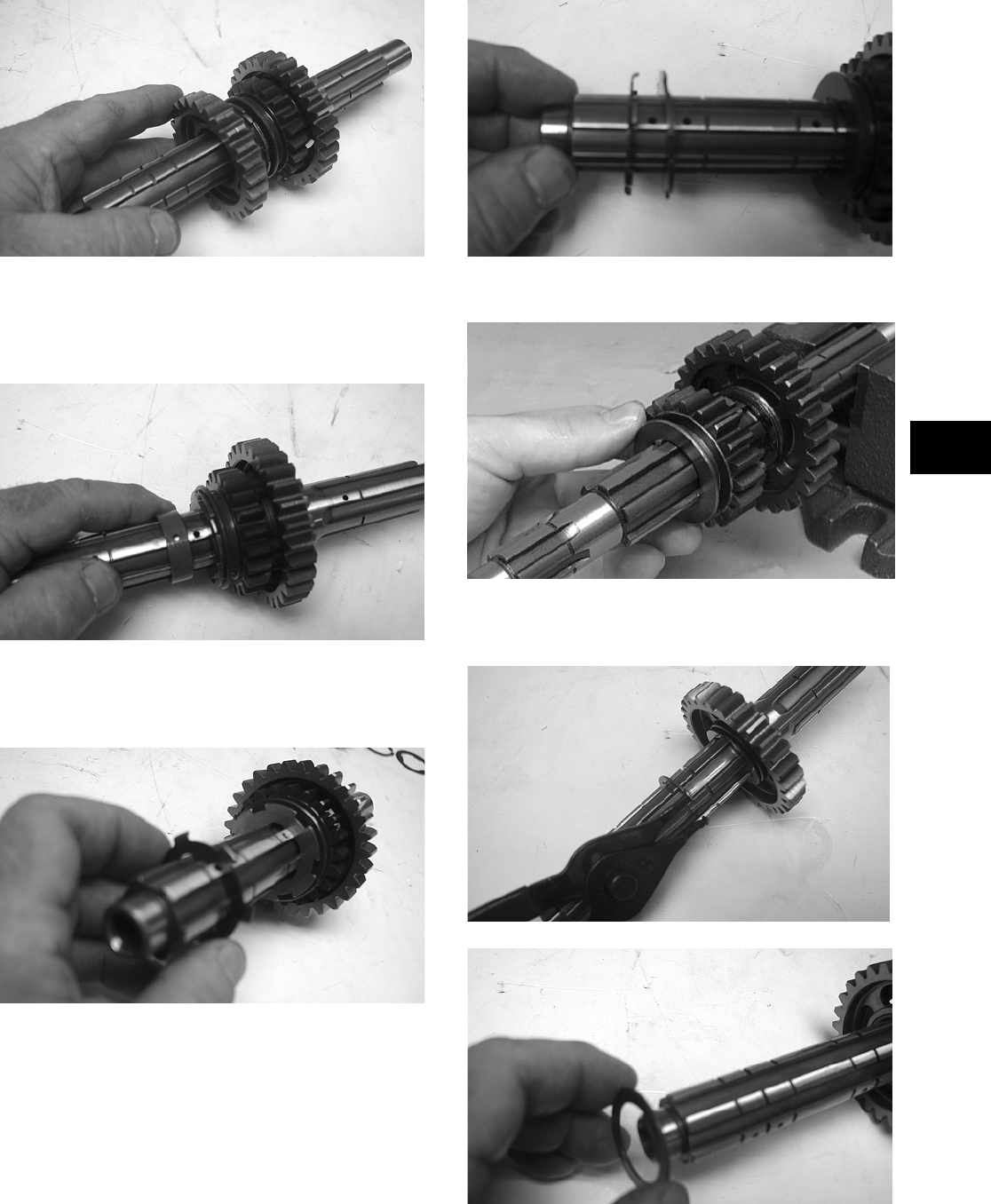
3-49
3
CD349
7. Remove the 3rd driven bushing from the drive-
shaft. Note the location of the oil feed hole in
the bushing and the matching oil supply hole in
the driveshaft for assembling purposes.
CD351
8. Remove the 3rd driven lock washer (left side)
from the driveshaft. Note the tabs facing toward
the 5th driven gear for assembling purposes.
CD352
9. Remove the next 3rd driven lock washer (left
side) by rotating it out of the groove. Note the
groove closest to the 5th driven gear for assem-
bling purposes.
CD354
10. Remove the 5th driven gear from the driveshaft.
CC210D
11. In order, remove the 2nd driven circlip, washer,
gear, and bushing from the driveshaft.
CD356
CD357
FOR ARCTIC CAT ATV DISCOUNT PARTS CALL 606-678-9623 OR 606-561-4983
www.mymowerparts.com
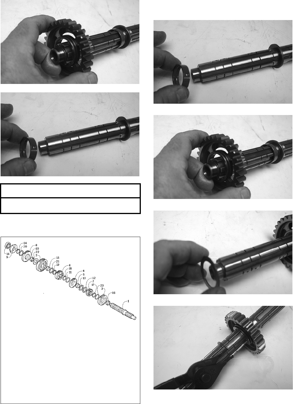
3-50
CD358
CD359
Assembling
737-733A
1. In order, install the 2nd driven bushing, gear,
washer, and circlip onto the driveshaft.
CD359
CD358
CD357
CD356
2. Install the 5th driven gear onto the driveshaft.
AT THIS POINT
To service secondary gears, see Servicing Center
Crankcase Components in this sub-section.
KEY
1. Driveshaft
2. 1st Driven Gear
3. 2nd Driven Gear
4. 3rd Driven Gear
5. 3rd Driven Bushing
6. 4th Driven Gear
7. 5th Driven Gear
8. Reverse Driven Gear
9. Reverse Dog
10. Reverse Driven Bushing
11. 3rd Driven Lock Washer —
Right
12. 3rd Driven Lock Washer —
Left
13. 3rd Driven Lock Washer —
Left
14. Driveshaft Bearing
15. 1st Driven Bushing
16. 2nd Driven Bushing
17. 2nd Driven Circlip
18. 3rd Driven Circlip
19. 4th Driven Circlip
20. Reverse Driven Washer
21. 1st Driven Washer — Left
22. 1st Driven Washer — Right
23. 2nd Driven Washer
24. Reverse Driven Circlip
FOR ARCTIC CAT ATV DISCOUNT PARTS CALL 606-678-9623 OR 606-561-4983
www.mymowerparts.com
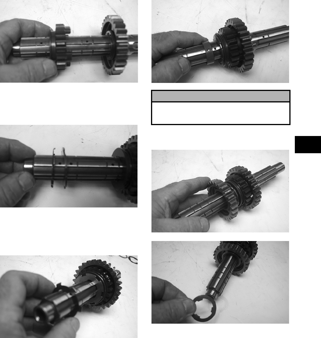
3-51
3
CD355
3. Install the 3rd driven lock washer (left side).
Lock it into the groove closest to the 5th driven
gear (as noted in disassembling) by rotating it
when it is in the groove.
CD354
4. Install the next 3rd driven lock washer (left side)
onto the driveshaft making sure the tabs are fac-
ing toward the 5th driven gear. Make sure the
tabs intertwine with the first 3rd driven lock
washer.
CD352
5. Install the 3rd driven bushing onto the driveshaft
making sure the oil feed hole in the bushing
aligns with the appropriate oil supply hole in the
driveshaft (as noted in disassembling).
CD351
6. In order, install the 3rd driven gear, lock washer
(right side), and circlip onto the driveshaft.
CD349
CD348
! CAUTION
It is very important to assure the oil feed hole in the
bushing and oil supply hole in the driveshaft align. If
not aligned, engine damage will result.
FOR ARCTIC CAT ATV DISCOUNT PARTS CALL 606-678-9623 OR 606-561-4983
www.mymowerparts.com
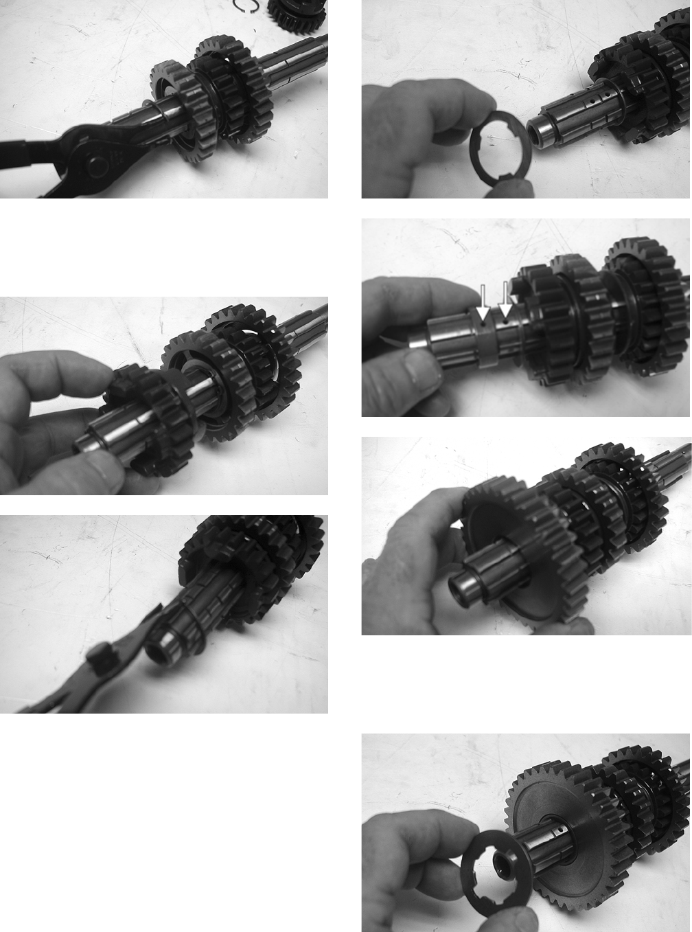
3-52
CD346
7. Install the 4th driven gear onto the driveshaft
making sure the four small dogs are facing
toward the 3rd driven gear as noted in disassem-
bling; then secure with the circlip.
CD345
CD344
8. Install the 1st driven washer (left side) onto the
shoulder of the splined shaft; then install the 1st
driven bushing and gear.
CD343
CD342A
CD341
9. Install the 1st driven washer (right side) on the
shaft making sure it lines up with the groove in
the shaft; then turn the washer locking it on the
shaft.
CD340
FOR ARCTIC CAT ATV DISCOUNT PARTS CALL 606-678-9623 OR 606-561-4983
www.mymowerparts.com
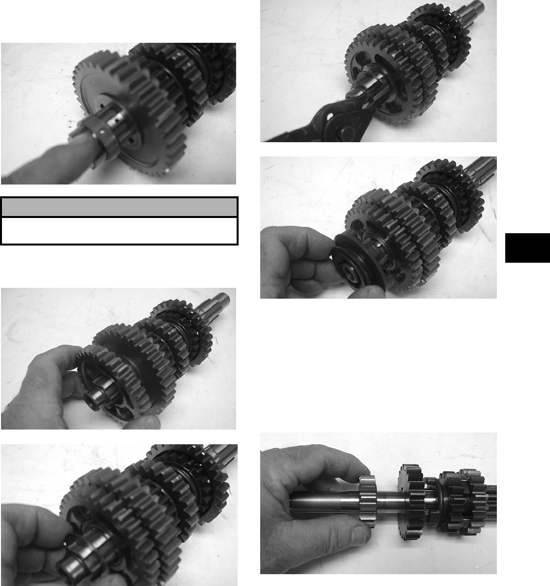
3-53
3
10. Slide the reverse driven bushing onto the shaft
making sure the oil port in the bushing aligns with
the oil port on the shaft.
CD337
11. In order, install the reverse driven gear, washer,
circlip, and reverse dog onto the driveshaft.
CD336
CD335
CD334
CD331
NOTE: The driveshaft is now completely assem-
bled for installation.
COUNTERSHAFT
Disassembling
1. Remove the 2nd drive gear from the counter-
shaft.
CD395
2. Remove the 5th drive gear from the counter-
shaft.
! CAUTION
Failure to align the oil ports will result in serious
engine damage.
FOR ARCTIC CAT ATV DISCOUNT PARTS CALL 606-678-9623 OR 606-561-4983
www.mymowerparts.com
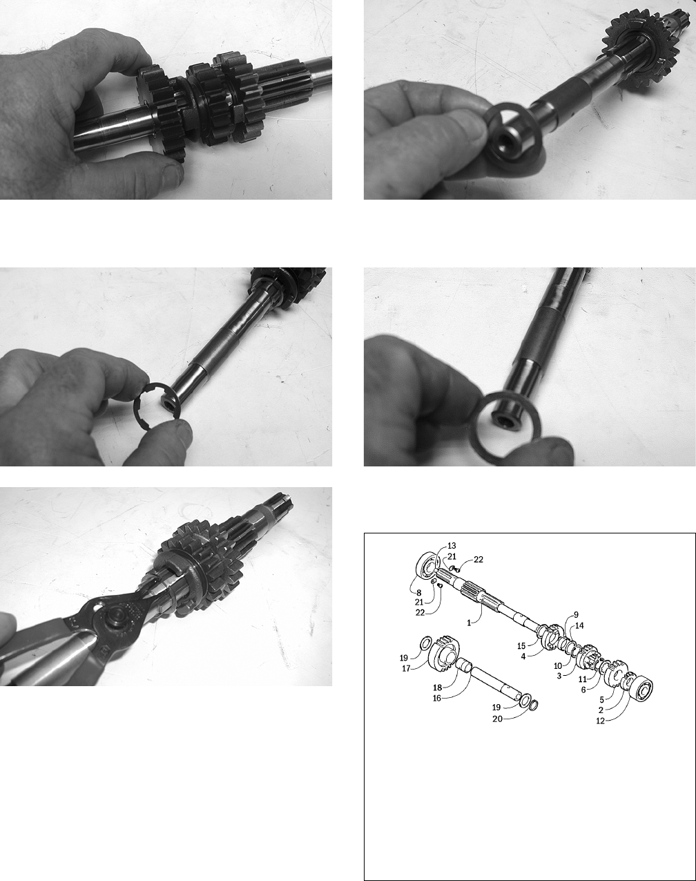
3-54
CD396
3. Remove the 5th drive washer and 5th drive cir-
clip from the countershaft.
CD397
CD400
4. Remove the 3rd drive gear from the counter-
shaft.
5. Remove the 4th drive circlip securing the 4th
drive gear on the countershaft; then remove the
first 4th drive washer and 4th drive gear.
Account for the bushing.
CD405
6. Remove the other 4th drive washer from the
countershaft.
CD408
Assembling
737-733B
1. Install the 4th drive washer onto the counter-
shaft.
KEY
1. Countershaft
2. 2nd Drive Gear
3. 3rd Drive Gear
4. 4th Drive Gear
5. 5th Drive Gear
6. 5th Drive Washer
7. 5th Drive Washer
8. Shaft Bearing
9. 4th Drive Bushing
10. 4th Drive Circlip
11. 5th Drive Circlip
12. Shaft Bearing
13. Plug
14. 4th Drive Washer
15. 4th Drive Washer
16. Reverse Idle Shaft
17. Reverse Idle Gear
18. Reverse Idle Bushing
19. Reverse Idle Washer
20. Reverse Idle Circlip
21. Retainer
22. Screw
FOR ARCTIC CAT ATV DISCOUNT PARTS CALL 606-678-9623 OR 606-561-4983
www.mymowerparts.com
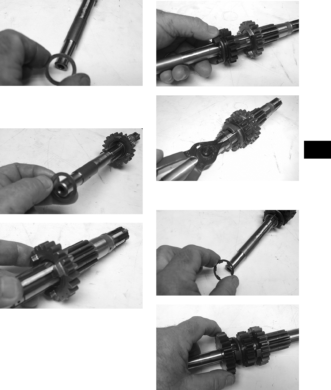
3-55
3
CD408
2. Install the 4th drive gear making sure the bush-
ing is in position; then install the other 4th drive
washer onto the countershaft. Secure with the
circlip.
CD405
CD406
3. Install the 3rd drive gear; then install the 5th
drive circlip onto the countershaft.
CD401
CD400
4. Install the 5th drive washer and 5th drive gear
onto the countershaft.
CD397
CD396
5. Install the 2nd drive gear onto the countershaft.
FOR ARCTIC CAT ATV DISCOUNT PARTS CALL 606-678-9623 OR 606-561-4983
www.mymowerparts.com
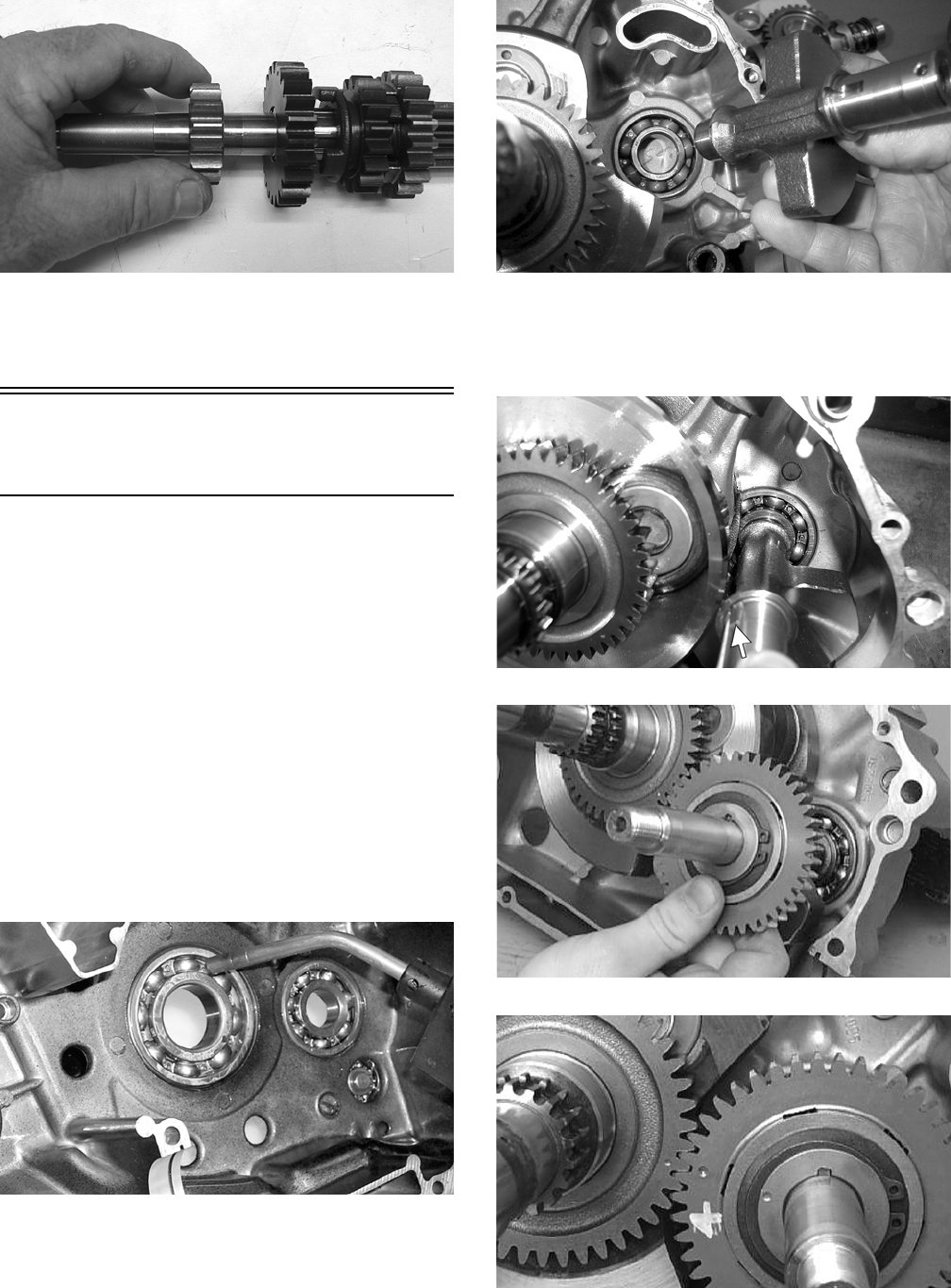
3-56
CD395
NOTE: The countershaft is now completely
assembled for installation.
Assembling Crankcase
Half
NOTE: For ease of assembly, install components
on the left-side crankcase half.
NOTE: If the output shaft and gear were
removed, make sure that the proper shim is
installed.
1. To install the output shaft and gear, place the
shaft into position with proper shims, slide the
gear onto the shaft, and secure with a new nut
tightened to specifications.
2. Apply a liberal amount of engine oil to the
crankshaft bearing. Using a propane torch, heat
the bearing until the oil begins to smoke; then
slide the crankshaft assembly into place. Install
the crank balancer.
MD1334
NOTE: If heating the bearing is not possible, the
crankshaft can be installed using a crankshaft
installing tool.
MD1024
3. With the key in position, slide the driven gear
onto the crank balancer making sure the timing
marks are aligned.
CD832A
CC167D
CC166D
FOR ARCTIC CAT ATV DISCOUNT PARTS CALL 606-678-9623 OR 606-561-4983
www.mymowerparts.com
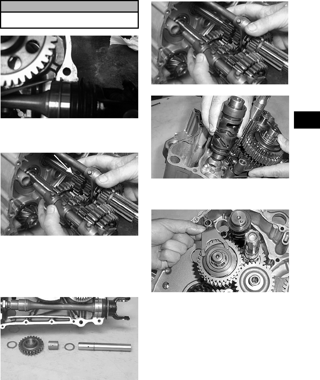
3-57
3
4. Place the bearing C-ring into position in the
crankcase; then install the front shaft and rear
shaft assemblies.
CD267
5. Simultaneously, install the driveshaft and coun-
tershaft assemblies making sure the washer is on
the countershaft.
CD232A
6. Install the reverse idle shaft with circlip making
sure the oil hole in the shaft is facing downward;
then install a washer, bushing, reverse idle gear,
and a washer.
NOTE: The reverse idle gear is directional. Care
must be taken that it is installed correctly.
CC231D
7. Place each of the four shift forks into its respec-
tive gear or dog as noted during disassembling;
then install the gear shift cam.
CD232
CC987
8. Engage the four forks to the gear shift cam; then
install the reverse shift cam and spacer.
CC986
NOTE: For proper assembling, the cam lock
plate must engage the shift cam cutaway.
! CAUTION
The bearing pins must be positioned into the crank-
case.
FOR ARCTIC CAT ATV DISCOUNT PARTS CALL 606-678-9623 OR 606-561-4983
www.mymowerparts.com
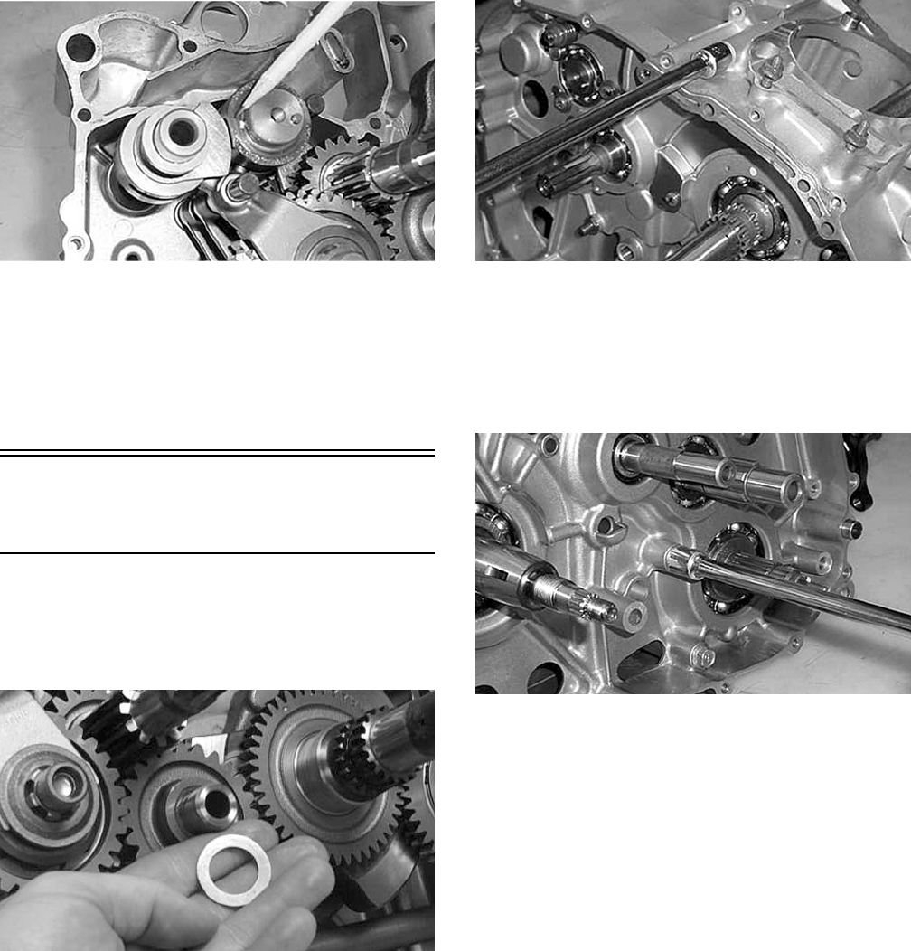
3-58
CC988
9. Install the two gear shift fork shafts; then verify
that the two crankcase half alignment pins are in
place.
NOTE: Prior to joining crankcase halves, turn the
shift cam to ensure all gears shift properly.
Joining Crankcase
Halves
1. Verify that the shim washer is on the idler shaft;
then apply Three Bond Sealant to the mating
surfaces. Place the right-side half onto the
left-side half.
CC102D
2. Using a plastic mallet, lightly tap the case halves
together until cap screws can be installed.
3. From the right side, install the four case half 8
mm cap screws; then tighten only until snug.
NOTE: Rotate the shafts back and forth to
ensure no binding or sticking occurs.
CC982
4. From the left side, install the three case half 8
mm cap screws (two inside the case); then
tighten only until snug.
NOTE: Rotate the shafts back and forth to
ensure no binding or sticking occurs.
CC981
5. From the left side, install the seven case half 6
mm cap screws; then tighten only until snug.
NOTE: Rotate the shafts back and forth to
ensure no binding or sticking occurs.
6. From the right side, install the five case half 6
mm cap screws (one inside the case); then
tighten only until snug.
NOTE: Rotate the shafts back and forth to
ensure no binding or sticking occurs.
7. In a crisscross/case-to-case pattern, tighten the 8
mm cap screws (from steps 3-4) until the halves
are correctly joined; then tighten to specifica-
tions.
NOTE: Rotate the shafts back and forth to
ensure no binding or sticking occurs.
8. In a crisscross/case-to-case pattern, tighten the 6
mm cap screws (from steps 5-6) to specifica-
tions.
FOR ARCTIC CAT ATV DISCOUNT PARTS CALL 606-678-9623 OR 606-561-4983
www.mymowerparts.com
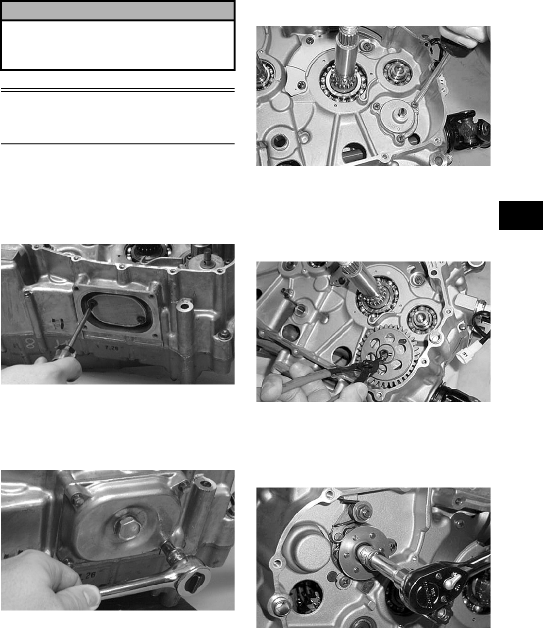
3-59
3
NOTE: Rotate the shafts back and forth to
ensure no binding or sticking occurs.
Installing Right-Side
Components
A. Oil Strainer/Oil Pump
B. Gear Shift Shaft
1. Place the oil strainer with a new O-ring into
position beneath the crankcase and tighten
securely with the Phillips-head cap screws.
CC163D
2. Place the strainer cap into position on the
strainer making sure the O-ring is properly
installed and secure with the cap screws; then
install and tighten the oil drain plug to specifica-
tions.
CC091D
3. Place the oil pump into position in the crankcase
and secure with the three Phillips-head screws
coated with blue Loctite #243. Tighten to speci-
fications.
CC978
4. Place the washer and pin into position on the oil
pump shaft, install the oil pump driven gear, and
secure with the circlip.
NOTE: Always use a new circlip when installing
the driven gear.
CC976
5. Place the gear shift cam plate and guide onto the
gear shift cam making sure the alignment pin
was installed. Secure assembly with the cap
screw coated with blue Loctite #243. Tighten
securely.
CC975
6. Attach the spring to the gear shift cam stopper
arm.
! CAUTION
After completing center crankcase components,
proceed to Installing Right-Side Components, to
Installing Left-Side Components, and to In- stalling
Top-Side Components.
FOR ARCTIC CAT ATV DISCOUNT PARTS CALL 606-678-9623 OR 606-561-4983
www.mymowerparts.com
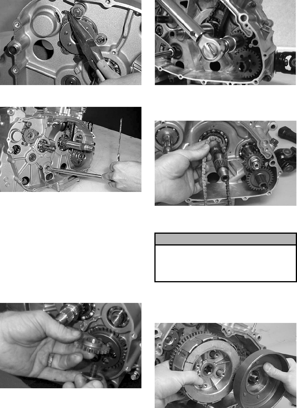
3-60
CC974
7. Install the gear shift shaft.
CC973
C. Primary Driven Gear
D. Primary Clutch
E. Centrifugal Clutch Shoe
NOTE: Steps 1-7 in the preceding sub-section
must precede this procedure.
8. Install the spacer, pin, and oil pump drive gear
onto the crank balancer shaft making sure the
shoulder of the drive gear is facing inward
toward the crankcase; then secure with the
washer and nut (threads coated with red Loctite
#271) tightened to specifications.
MD1017
CD447
9. Place the chain into the crankcase; then secure it
from the top side with a wire for ease of install-
ing.
CC079D
10. Install the primary driven washers and shims
onto the driveshaft and crankshaft.
11. Simultaneously, place the primary clutch assem-
bly and the centrifugal clutch housing on their
respective shafts making sure the sleeve is prop-
erly positioned in the primary assembly.
CC078D
! CAUTION
The clutch sleeve hub and the clutch pressure plate
must be seated in the proper position. If any of the
incorrect positions are used, the hub and plate will
have clearance between them and they will not oper-
ate properly.
FOR ARCTIC CAT ATV DISCOUNT PARTS CALL 606-678-9623 OR 606-561-4983
www.mymowerparts.com
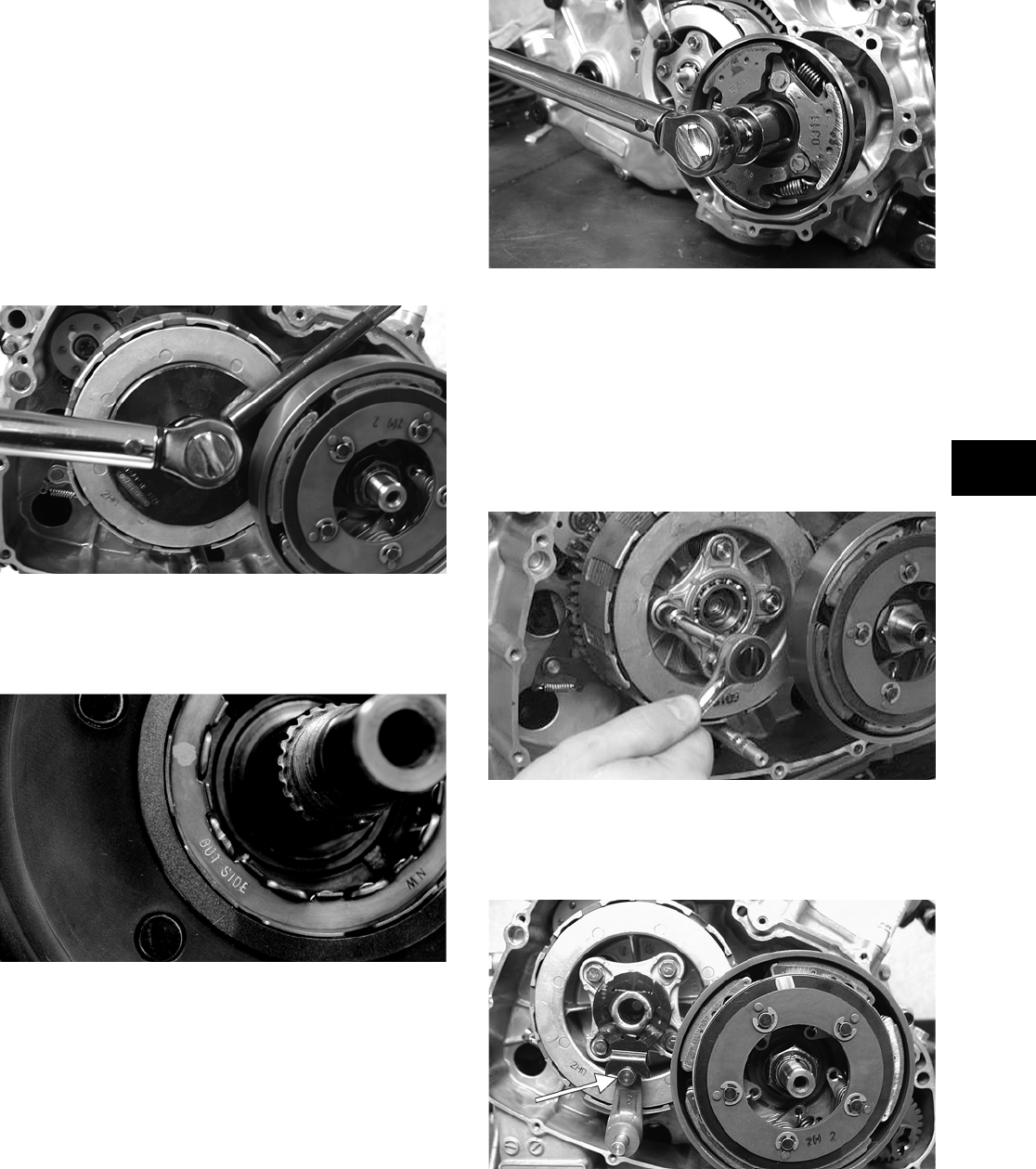
3-61
3
NOTE: After placing the primary clutch assembly
onto the shaft, pull out on the pressure plate tower
to ensure the pressure plate has engaged the
clutch hub properly and make sure the plates
(drive and driven) are brought together tightly
prior to tightening the nut securing the clutch
assembly.
12. Using a clutch sleeve hub holder, install the nut
and washer. Tighten to specifications.
NOTE: The washer is directional. Care must be
taken to install it correctly.
CD448
13. Place the primary drive one-way clutch into the
centrifugal clutch housing noting the word
OUTSIDE for proper placement.
CF043
14. Install the centrifugal clutch shoe and washer;
then secure with the centrifugal clutch-shoe nut
(left-hand threads). Tighten to specifications;
then using a center punch, stake the nut.
CD440
15. Install the release roller assembly making sure
the four springs are in position; then using a
crisscross pattern, tighten the four cap screws
securely.
NOTE: Tighten the four roller assembly cap
screws in a crisscross pattern making sure there
is no clearance between the clutch plates when
secured.
CC074D
16. Install the clutch release arm and release roller
guide making sure the release roller and guide
are aligned.
CD166A
17. Secure the clutch release arm with the cap screw
coated with blue Loctite #243. Tighten securely.
FOR ARCTIC CAT ATV DISCOUNT PARTS CALL 606-678-9623 OR 606-561-4983
www.mymowerparts.com
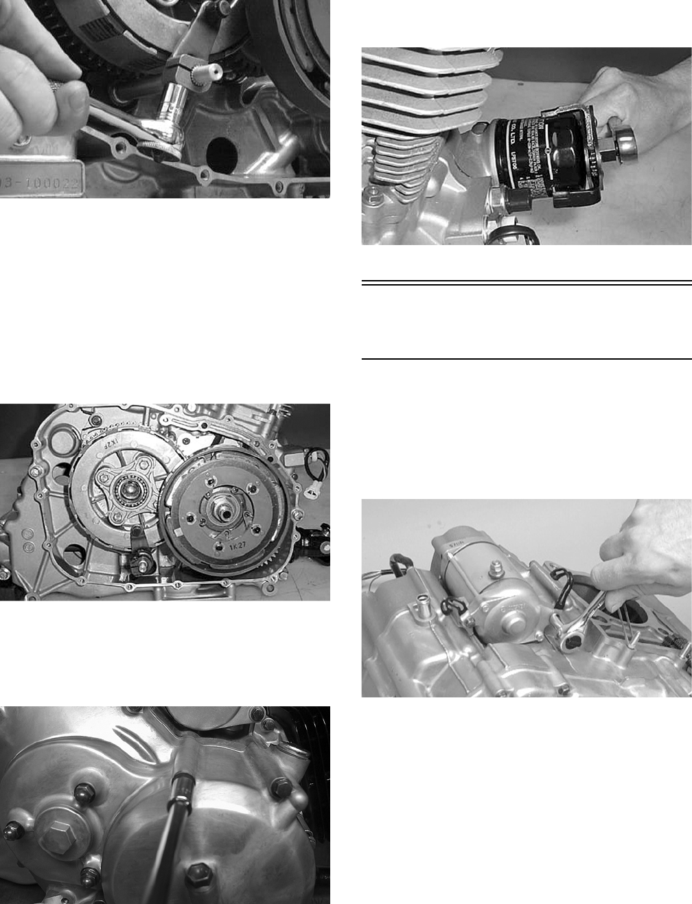
3-62
CC073D
F. Oil Filter
NOTE: Steps 1-17 of the preceding sub-sections
must precede this procedure.
NOTE: Lubricate all internal components with
5W-30 oil prior to installing the right-side cover.
NOTE: Care should be taken that the alignment
pins are installed in the right-side cover.
CC989
18. Place the gasket and right-side cover into posi-
tion making sure the release roller guide remains
correctly positioned; then install the fifteen cap
screws.
CD441
19. Tighten the cap screws in a crisscross pattern to
specifications.
20. Using the oil filter wrench, install a new oil fil-
ter.
CC967
Installing Left-Side
Components
A. Idle Gear Assembly
B. Magneto Rotor
1. Place the starter into position on the crankcase
and secure with the cap screws. Note the posi-
tion of the wiring form.
CC065D
2. Place the neutral switch base assembly into
position making sure the two neutral contacts
and springs are inside the case and properly
positioned. Secure with Allen-head screws.
FOR ARCTIC CAT ATV DISCOUNT PARTS CALL 606-678-9623 OR 606-561-4983
www.mymowerparts.com
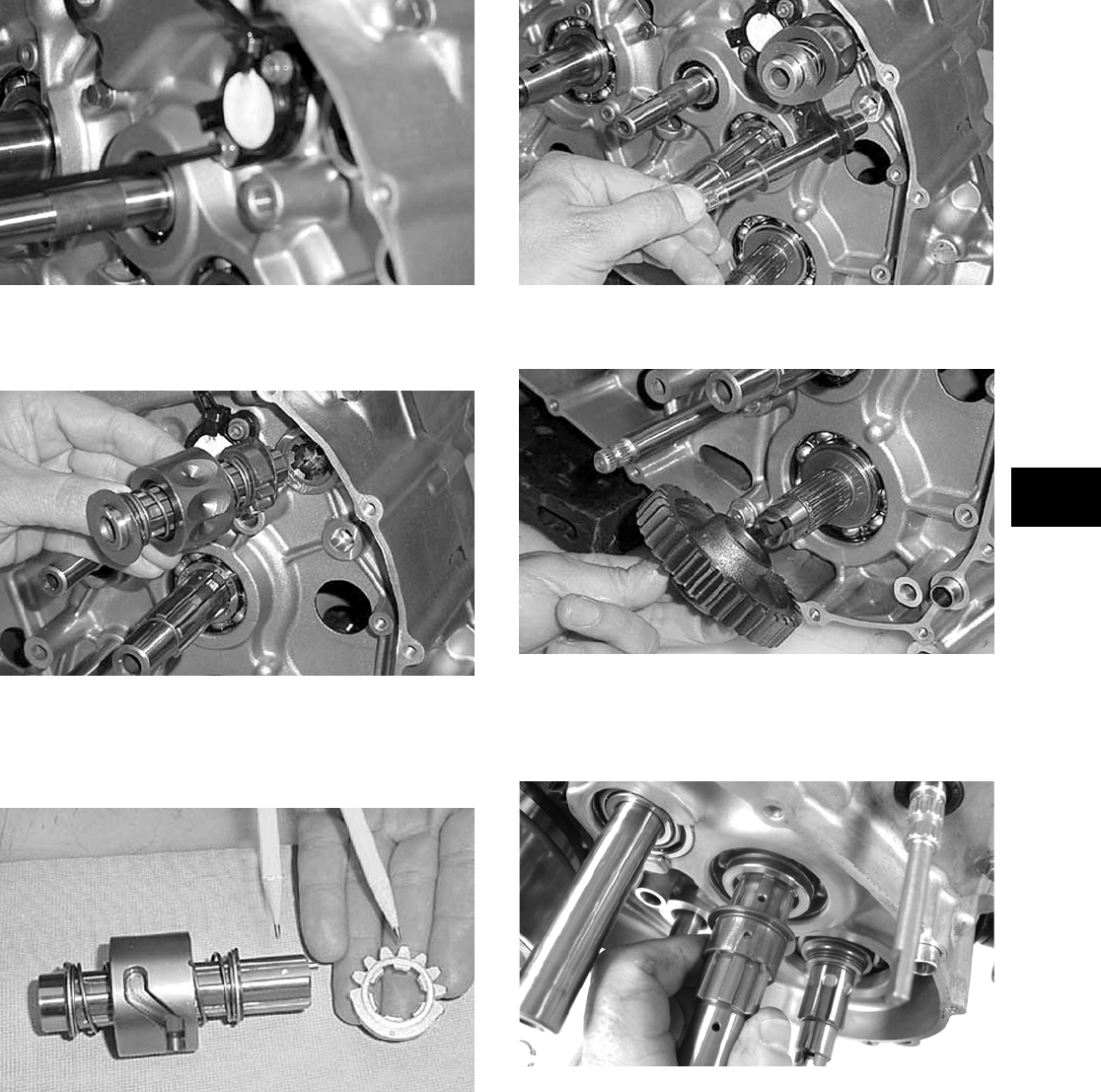
3-63
3
CC964
3. Install the secondary stopper camshaft w/one
inner shim and one outer shim.
CC962
NOTE: Care must be taken that the alignment
dots on the camshaft plate and the camshaft are
properly aligned.
CC963
4. Install the gear shift shaft w/one inner washer
and one outer washer.
CC960
5. Install the driven gear onto the output shaft.
CC959
6. Place the bushing and washer onto the drive-
shaft making sure the oil hole of the bushing
aligns with the oil hole of the driveshaft.
CD552
7. In turn on the driveshaft, install drive gear #1
and a washer; then secure with the circlip.
FOR ARCTIC CAT ATV DISCOUNT PARTS CALL 606-678-9623 OR 606-561-4983
www.mymowerparts.com
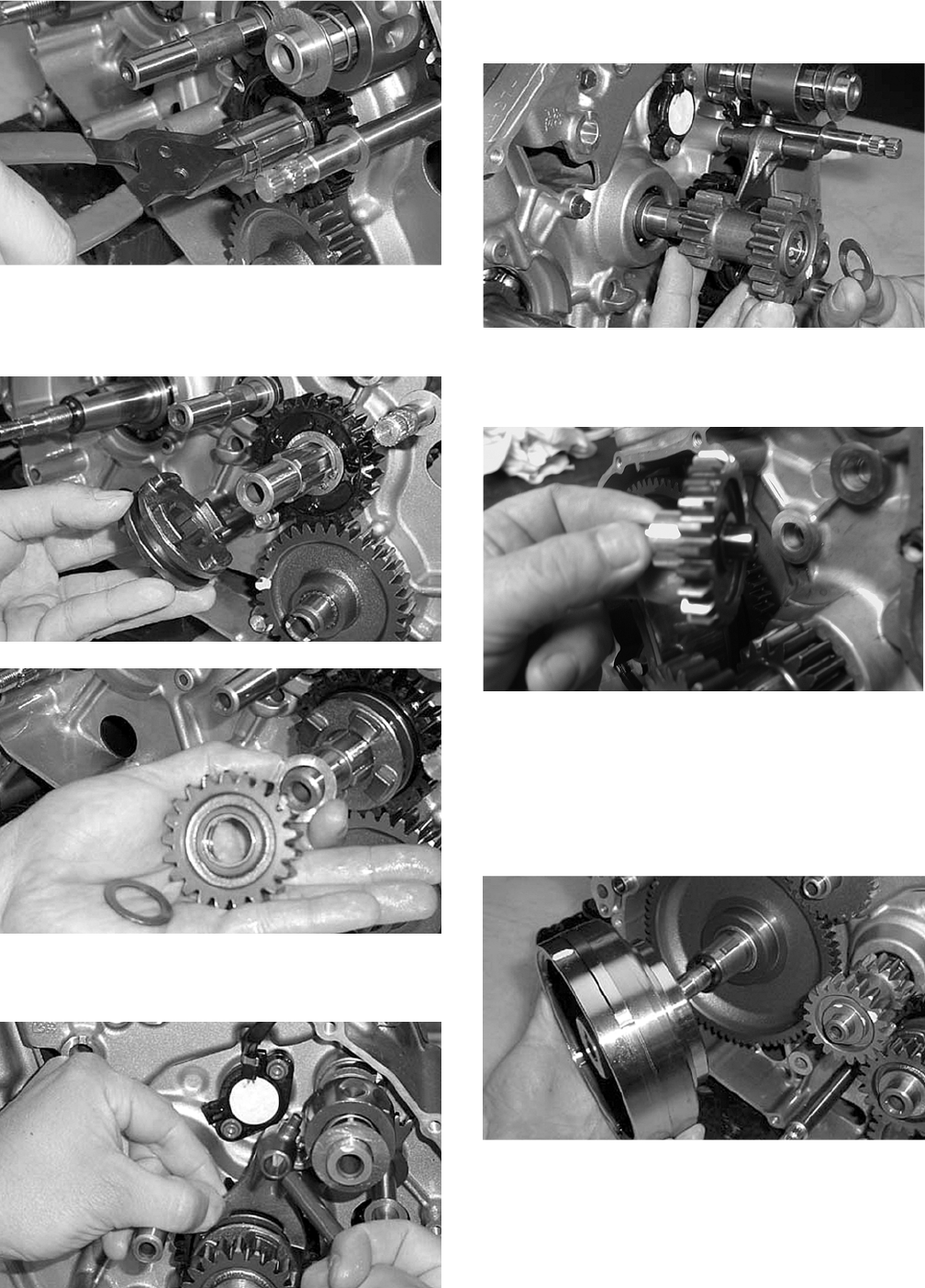
3-64
CC955
8. Place the select sliding dog gear onto the drive-
shaft; then place a washer, drive gear #2, and
another washer onto the driveshaft.
CC966
CC954
9. Place the gear shift fork into the sliding dog;
then install the gear shift fork shaft.
CC953
10. Install the drive idler gear with one spacer and
one washer.
CC952
11. Install starter idler gear #2 and shaft with the
chamfered side directed toward the crankcase.
CD140
12. Install the starter clutch gear assembly onto the
crankshaft. Place the key into its notch. Place
the magneto rotor into position on the crank-
shaft; then install the magneto rotor nut on the
crankshaft and tighten until the rotor is properly
seated. Tighten to specifications.
CC991
FOR ARCTIC CAT ATV DISCOUNT PARTS CALL 606-678-9623 OR 606-561-4983
www.mymowerparts.com
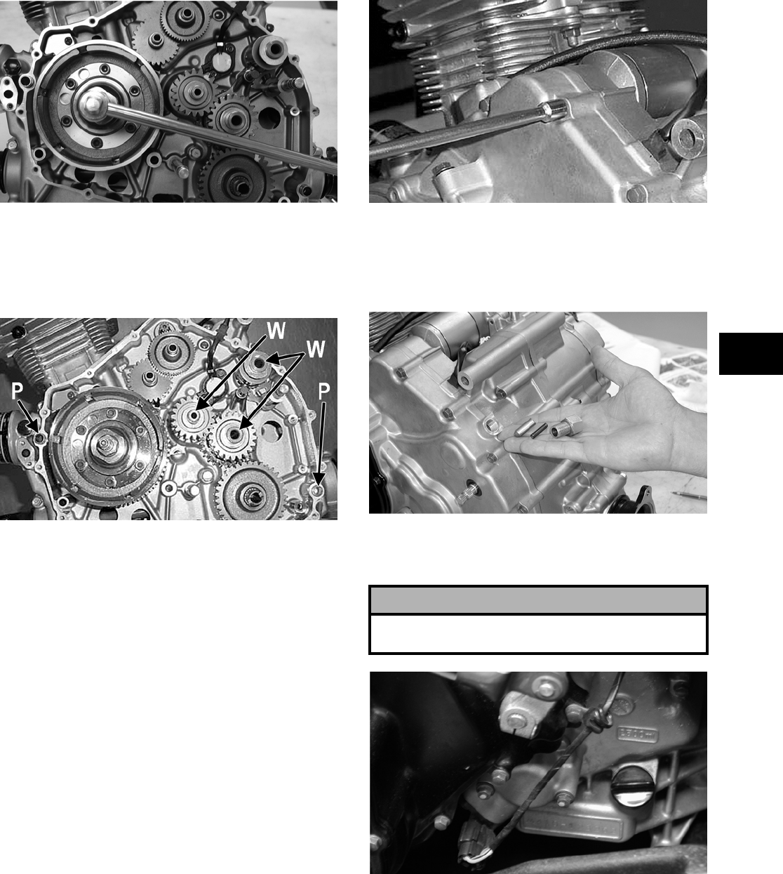
3-65
3
CC990
13. Install the two alignment pins into the left
crankcase half.
NOTE: Make sure that three washers and two
alignment pins are in place.
CC948A
C. Cover
D. Speedometer Drive
E. Hi/Low Shifter Assembly
F. Recoil Starter
NOTE: Steps 1-13 in the preceding sub-section
must precede this procedure.
14. Place the gasket and left-side cover into position
on the crankcase.
NOTE: It may be necessary to push or pull the
splined Hi/Low range shift shaft to establish
cover/crankcase mating.
15. Install the fifteen 6 mm cap screws and one 8
mm cap screw to secure the left-side cover. Only
finger-tighten at this time.
CC945
16. Place the gear shift stopper w/spring and washer
into position above the hi/low shift shaft making
sure the spring and stopper are correctly posi-
tioned. Tighten to specifications.
CC993
17. Place the speed sensor into position and secure
with the two cap screws. Tighten securely.
CF109
18. Place the starter cup into position on the crank-
shaft making sure a new, lubricated O-ring is
inside the cup. Tighten the flange nut to specifi-
cations.
! CAUTION
Make sure the speedometer gear and output shaft
gear match up during assembly.
FOR ARCTIC CAT ATV DISCOUNT PARTS CALL 606-678-9623 OR 606-561-4983
www.mymowerparts.com
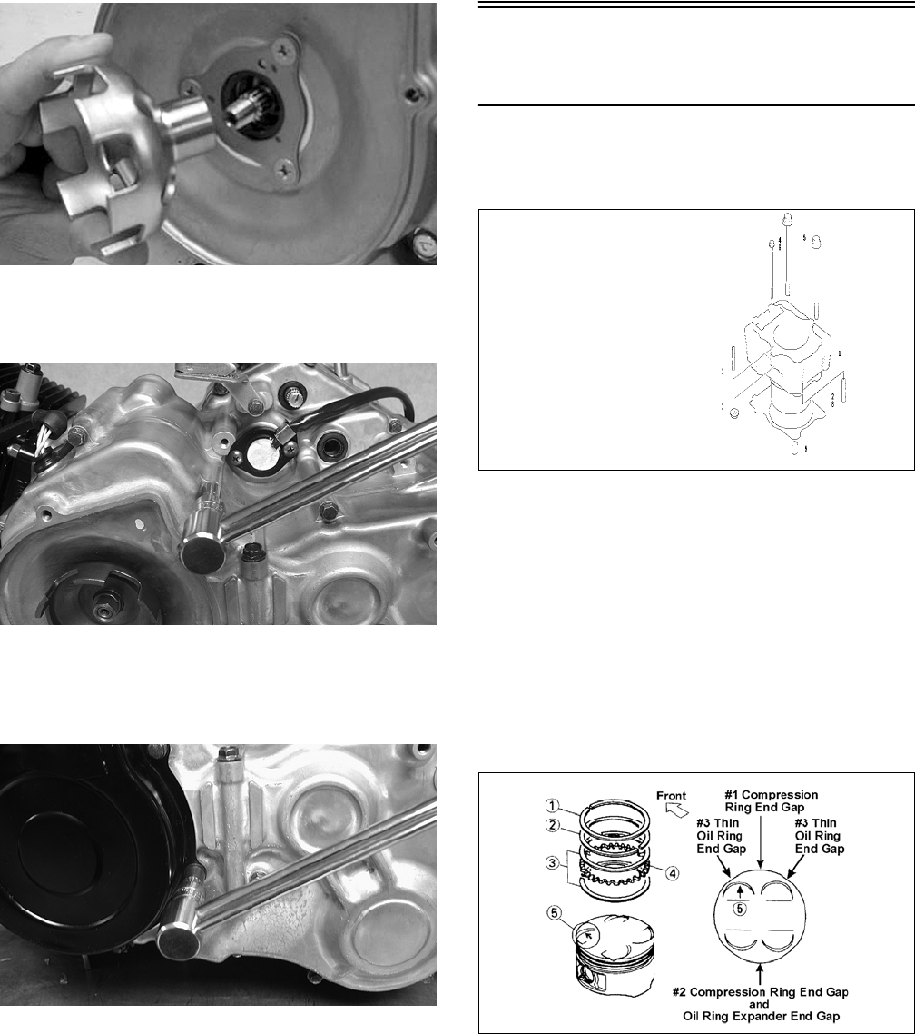
3-66
CC943
19. In a crisscross pattern, tighten the cap screws
(from step 15) to specifications.
CD429
20. Place the recoil starter assembly into position on
the left-side cover; then tighten four cap screws
to specifications.
CD431
Installing Top-Side
Components
A. Piston
B. Cylinder
0737-039
NOTE: If the piston rings were removed, install
them in this sequence.
A. Install ring expander (4) in the bottom groove
of the piston; then install the thin oil rings (3)
over the expander making sure the expander
ends do not overlap. Stagger the end gaps of the
upper and lower thin oil rings according to the
illustration.
NOTE: Note the direction of the exhaust side of
the piston (5) for correct ring end gap orientation.
ATV-1085B
B. Install the compression rings (1 and 2) so the
letter on the top surface of each ring faces the
dome of the piston. Rotate the rings until the
ring end gaps are on directly opposite sides of
the piston (see illustration).
NOTE: The chrome (silver) ring should be
installed in the top position.
KEY
1. Cylinder
2. Stud Bolt
3. Stud Bolt
4. Bolt
5. Bolt
6. Bolt
7. Nut
8. Cylinder Gasket
9. Pin
FOR ARCTIC CAT ATV DISCOUNT PARTS CALL 606-678-9623 OR 606-561-4983
www.mymowerparts.com
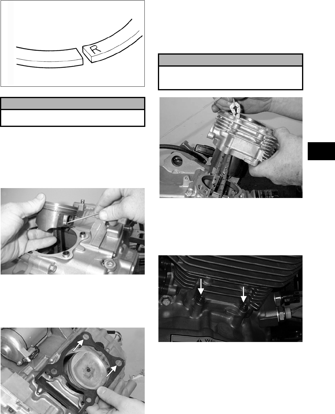
3-67
3
ATV-1024
1. Install the piston on the connecting rod making
sure there is a circlip on each side and the open
end of the circlip is directed upwards or down-
wards.
NOTE: The piston should be installed so the
arrow points toward the exhaust.
MD1213
2. Place the two alignment pins into position. Place
the cylinder gasket into position; then place a
piston holder (or suitable substitute) beneath the
piston skirt and square the piston in respect to
the crankcase.
MD1344
3. Lubricate the inside wall of the cylinder; then
using a ring compressor or the fingers, compress
the rings and slide the cylinder over the piston.
Route the cam chain up through the cylinder
cam chain housing; then remove the piston
holder and seat the cylinder firmly on the crank-
case.
MD1345
4. Loosely install the two nuts with washers which
secure the right-side of the cylinder to the
right-side crankcase half.
NOTE: The two cylinder-to-crankcase nuts will
be tightened in step 9.
CF162A
! CAUTION
Incorrect installation of the piston rings will result in
engine damage.
! CAUTION
The cylinder should slide on easily. Do not force the
cylinder or damage to the piston, rings, cylinder, or
crankshaft assembly may occur.
FOR ARCTIC CAT ATV DISCOUNT PARTS CALL 606-678-9623 OR 606-561-4983
www.mymowerparts.com
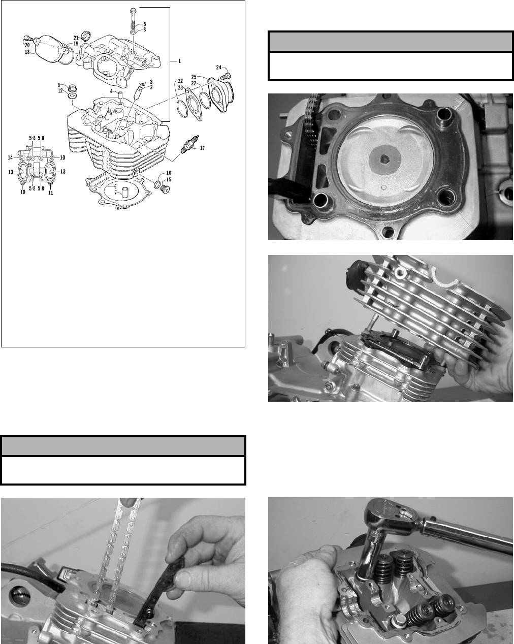
3-68
C. Cylinder Head
D. Valve Cover
0737-038
NOTE: Steps 1-4 in the preceding sub-section
must precede this procedure.
5. While keeping tension on the cam chain, place
the chain guide into the cylinder.
MD1349
6. Place the head gasket into position on the cylin-
der. Place the alignment pins into position; then
place the head assembly into position on the cyl-
inder making sure the cam chain is routed
through the chain cavity.
MD1347
MD1163
7. Install the four cylinder head cap screws with
washers. Note that the two cap screws on the
right side of the cylinder head nearest the cam
sprocket are longer than the two cap screws on
the left (spark plug) side. Tighten only until
snug.
MD1270
8. Install the two lower nuts securing the cylinder
head to the cylinder, one in front and one in rear.
Tighten only until snug.
! CAUTION
Care should be taken that the bottom of the chain
guide is secured in the crankcase boss.
KEY
1. Cylinder Head Assy
2. Valve Guide
3. Ring
4. Pin
5. Cap Screw
6. Cylinder Head Gasket
7. Pin
8. Gasket
9. Nut
10. Cap Screw
11. Cap Screw
12. Washer
13. Cap Screw
14. Cap Screw
15. Plug
16. Gasket
17. Spark Plug
18. Inspection Cap
19. O-Ring
20. Cap Screw
21. Plug
22. O-Ring
23. Insulator
24. Screw
25. Intake Manifold
! CAUTION
Keep tension on the cam chain to avoid damaging
the crankcase boss.
FOR ARCTIC CAT ATV DISCOUNT PARTS CALL 606-678-9623 OR 606-561-4983
www.mymowerparts.com
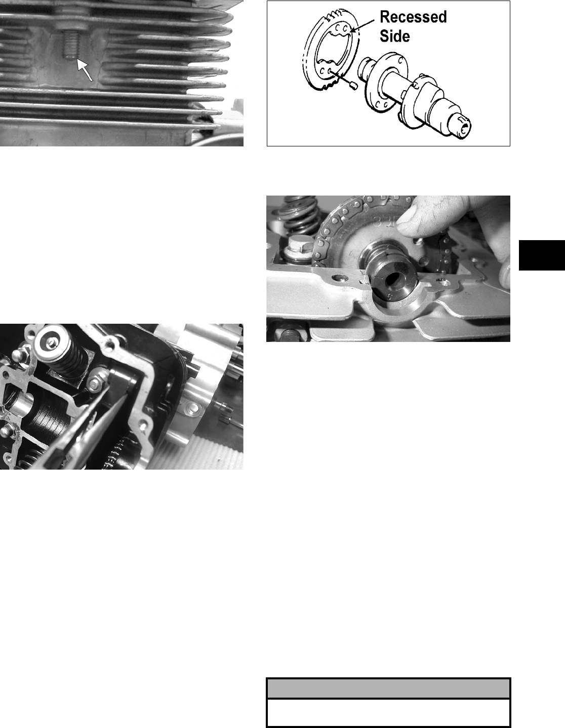
3-69
3
MD1192
9. In a crisscross pattern, tighten the four cylinder
head cap screws (from step 7) to specifications;
then tighten the nuts (from step  to specifica-
tions. Tighten the cylinder-to-crankcase nuts
(from step 4) to specifications.
10. With the timing inspection plug removed and
the chain held tight, rotate the crankshaft until
the piston is at top-dead-center.
11. Install the rear cam chain tensioner guide into
the cylinder head. Install the pivot cap screw
and washer.
CD383
12. With the alignment pin installed in the camshaft
and the cam lobes directed down (toward the
piston), place the camshaft in position and verify
that the timing mark on the magneto is visible
through the inspection plug and that the timing
marks on the camshaft sprocket are parallel with
the valve cover mating surface.
NOTE: When the camshaft assembly is seated,
make sure the alignment pin in the camshaft aligns
with the smallest hole in the sprocket.
13. Loosely place the cam sprocket (with the
recessed side facing the camshaft lobes) onto the
camshaft and place it into position with the cam
chain over the sprocket.
732-307B
14. Place the C-ring into position in its groove in the
cylinder head.
MD1131
NOTE: At this point, oil the camshaft bearings,
cam lobes, and the three seating journals on the
cylinder.
NOTE: Note the position of the alignment marks
on the end of the camshaft. They must be parallel
with the valve cover mating surface. If rotating the
camshaft is necessary for alignment, do not allow
the chain and sprocket to rotate and be sure the
cam lobes end up in the down position.
15. When the camshaft assembly is seated, ensure
the following.
A. Piston still at top-dead-center.
B. Camshaft lobes directed down (toward the
piston).
C. Camshaft alignment marks parallel to the valve
cover mating surface.
D. Recessed side of the sprocket directed toward
the cam lobes.
E. Camshaft alignment pin and sprocket
alignment hole (smallest) are aligned.
! CAUTION
If any of the above factors are not as stated, go back
to step 10 and carefully proceed.
FOR ARCTIC CAT ATV DISCOUNT PARTS CALL 606-678-9623 OR 606-561-4983
www.mymowerparts.com
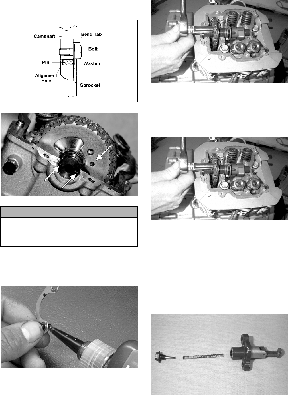
3-70
16. Place the tab washer onto the sprocket making
sure it covers the pin in the alignment hole.
ATV-1027
CF030B
17. Apply red Loctite #271 to the first cap screw
securing the sprocket and tab washer to the cam-
shaft; then install the cap screw. Tighten cap
screw only until snug.
CC404D
MD1137
18. Rotate the crankshaft until the second cap screw
securing the sprocket to the camshaft can be
installed; then install the cap screw (threads
coated with red Loctite #271). Tighten to speci-
fications; then bend the tab to secure the cap
screw.
MD1137
19. Rotate the crankshaft until the first cap screw
securing the sprocket to the camshaft (from step
17) can be addressed; then install the cap screw.
Tighten to specifications; then bend the tab to
secure the cap screw.
20. Install the cylinder head plug in the cylinder
head with the open end facing the cylinder head.
21. Remove the cap screw from the end of the chain
tensioner; then account for the plunger, spring,
and O-ring.
MD1248
! CAUTION
Care must be taken that the tab washer is installed
correctly to cover the alignment hole on the
sprocket. If the alignment pin falls out, severe
engine damage will result.
FOR ARCTIC CAT ATV DISCOUNT PARTS CALL 606-678-9623 OR 606-561-4983
www.mymowerparts.com
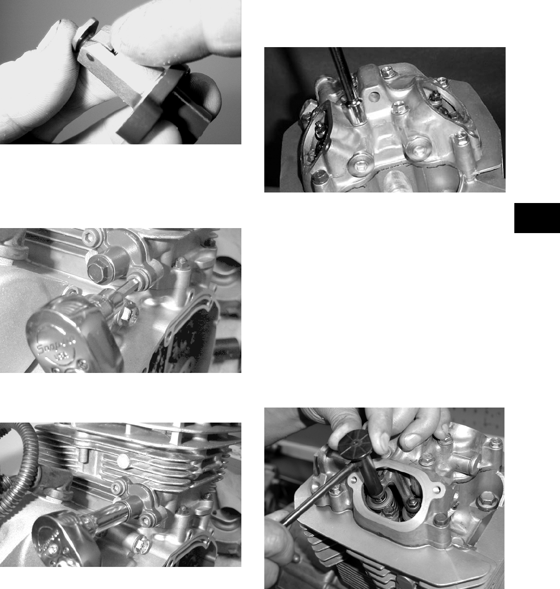
3-71
3
22. Depress the spring-loaded lock and push the
plunger into the tensioner.
MD1146
23. Place the chain tensioner adjuster assembly and
gasket into position on the cylinder making sure
the ratchet side is facing toward the top of the
cylinder and secure with the two Allen-head
screws.
MD1254
24. Install the cap screw and spring into the end of
the chain tensioner. Tighten securely.
MD1245
25. Loosen the adjuster screw jam nuts; then loosen
the adjuster screws on the rocker arms in the
valve cover.
26. Apply a thin coat of Three Bond Sealant to the
mating surface of the valve cover. Place the
valve cover into position making sure the two
alignment pins are properly positioned.
NOTE: At this point, the rocker arms and
adjuster screws must not have pressure on them.
27. Install the four top-side cap screws with rubber
washers; then install the remaining cap screws.
Tighten only until snug.
CC999
28. In a crisscross pattern starting from the center
and working outward, tighten the cap screws
(from step 27) to specifications.
29. Adjust valve/tappet clearance using the follow-
ing procedure.
NOTE: Use Valve Clearance Adjuster (p/n
0444-078) for this procedure.
A. Turn the engine over until the piston reaches
top dead center on the compression stroke.
B. Place the valve adjuster onto the jam nut
securing the tappet adjuster screw; then rotate
the valve adjuster dial clockwise until the end is
seated in the tappet adjuster screw.
CD001
C. While holding the valve adjuster dial in place,
use the valve adjuster handle and loosen the
jam nut; then rotate the tappet adjuster screw
clockwise until friction is felt.
D. Align the valve adjuster handle with one of the
marks on the valve adjuster dial.
FOR ARCTIC CAT ATV DISCOUNT PARTS CALL 606-678-9623 OR 606-561-4983
www.mymowerparts.com
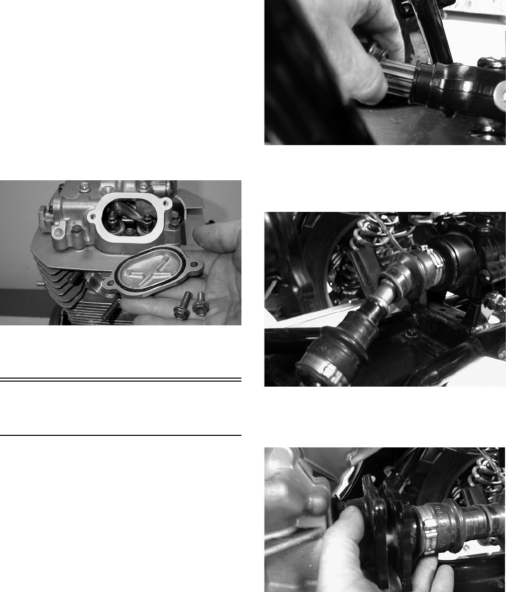
3-72
E. While holding the valve adjuster handle in
place, rotate the valve adjuster dial
counterclockwise until specified valve/tappet
clearance is attained.
NOTE: Rotating the valve adjuster dial counter-
clockwise will open the valve/tappet clearance by
0.05 mm (0.002 in.) per mark.
F. While holding the adjuster dial at the proper
clearance setting, tighten the jam nut securely
with the valve adjuster handle.
30. Place the two tappet covers into position; then
install and tighten the cap screws securely.
MD1264
31. If removed, install the spark plug and tighten to
specifications.
Installing
Engine/Transmission
NOTE: Arctic Cat recommends that new gaskets
and O-rings be installed whenever servicing the
ATV.
1. From the left side, place the engine/transmission
into the frame; then move it rearward as far as
possible.
2. Raise the rear of the engine enough to engage
the front driveshaft into the splines of the front
drive output yoke; then slide the engine forward
as far as possible.
CD818
3. Raise the rear of the engine and place a block
under it; then install the propeller shaft and out-
put flange into the rear drive coupler.
CD821
4. Remove the block from beneath the engine; then
align the rear drive flanges and secure with four
cap screws. Tighten to specifications.
CD824
5. Install the lower rear engine mounting
through-bolt, spacer, and washer; then install the
lower front engine mounting through-bolt,
spacer, and washer. Secure with the flange nuts.
Tighten to specifications.
FOR ARCTIC CAT ATV DISCOUNT PARTS CALL 606-678-9623 OR 606-561-4983
www.mymowerparts.com
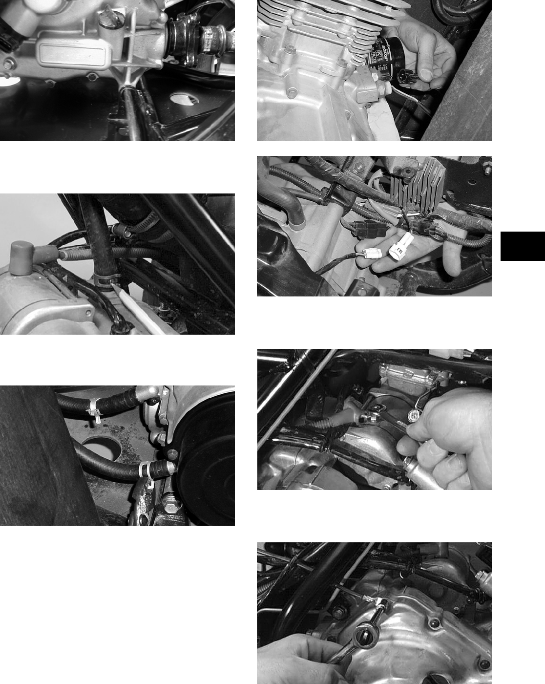
3-73
3
CD809
6. Connect the crankcase breather vent hose and
secure with the clamp.
CC122D
7. Connect the oil cooler hoses to the engine and
secure with the clamps.
CC937
8. Connect the following electrical components: two
wire leads for the oil temperature and oil pressure
sensors, indicator lights, CDI, and voltage
regulator.
CC939
CC938
9. Connect the positive cable to the starter motor
and install the protective boot.
AR604D
10. Connect the battery ground (negative) cable to
the crankcase cover.
AR600D
FOR ARCTIC CAT ATV DISCOUNT PARTS CALL 606-678-9623 OR 606-561-4983
www.mymowerparts.com
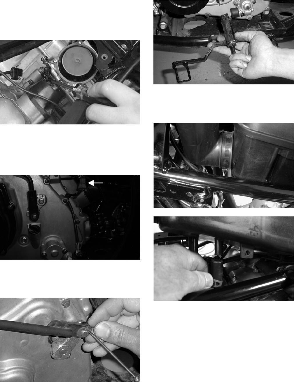
3-74
11. Install the coil and connect the two wires; then
install the high tension lead on the spark plug.
12. Install the carburetor assembly and secure the
intake manifold and air inlet boot.
CC120D
13. Route the two vent hoses through the slots in the
frame.
14. Connect the speed sensor lead to the wiring har-
ness.
CF172A
15. Place the reverse/high/low shift linkage w/bush-
ing and washer onto the engine shift shaft and
secure with the E-clip.
CC935
16. Place the gear shift lever into position on the
shaft on the engine; then secure with the pinch
screw and lock nut.
CC934
17. Install the air filter housing; then connect the
crankcase breather and the inlet air duct. Secure
with the clamps.
CD785
CD787
18. Install the exhaust pipe and secure with two cap
screws; then install the muffler onto the frame
brackets and secure with exhaust springs.
FOR ARCTIC CAT ATV DISCOUNT PARTS CALL 606-678-9623 OR 606-561-4983
www.mymowerparts.com
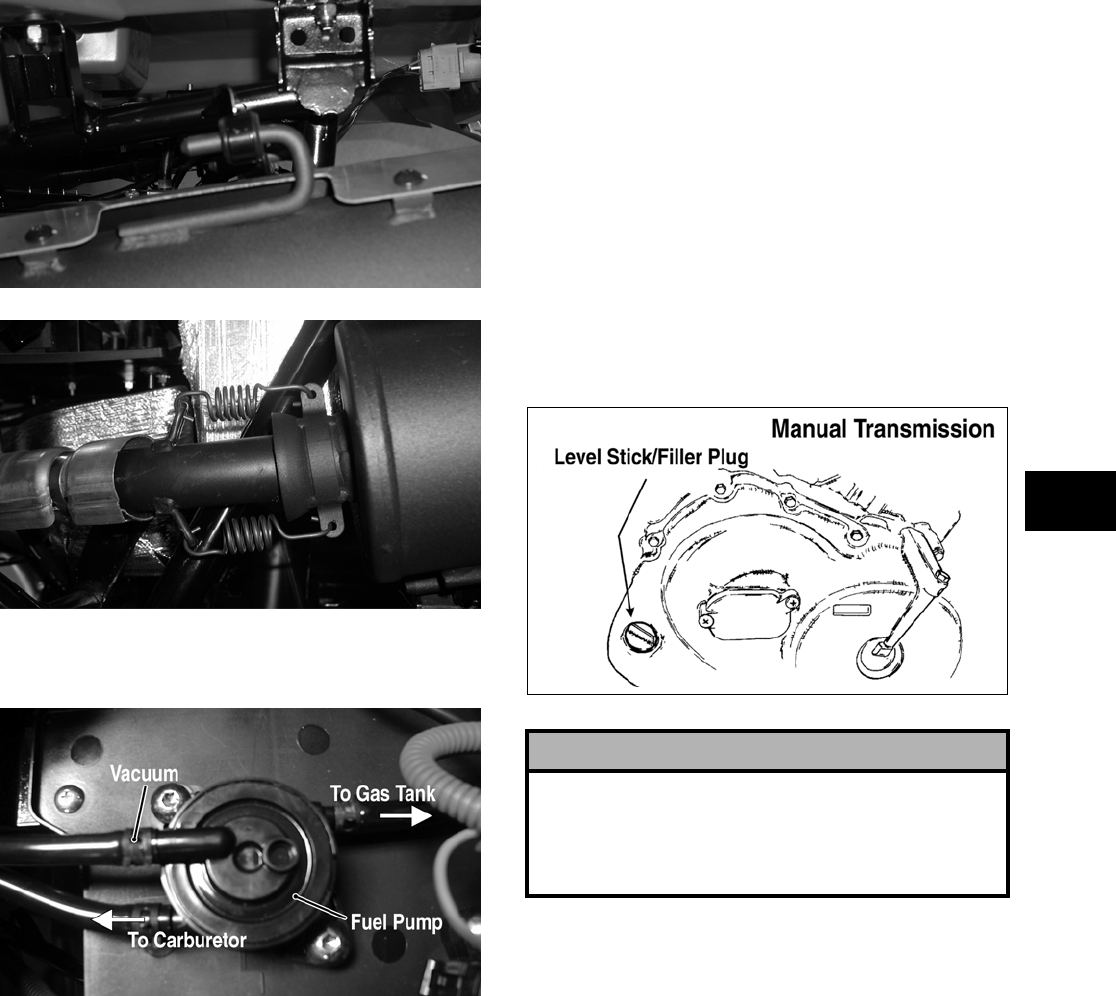
3-75
3
CF137
CF138
19. Connect the gas hose to the fuel pump; then con-
nect the vacuum hose. Secure with hose clamps.
CD766A
20. Install the front and rear fender panels and the
front and rear racks (see Section 8).
21. Install the storage compartment and steering
post access panel; then secure with reinstallable
rivets.
22. Install the battery in the tray, install the vent
hose. Connect the positive battery cable; then
connect the negative cable. Install the battery
cover/tool tray.
23. Install the seat.
24. Pour the correct amount of recommended oil
into the engine/transmission filler hole; install
the filler plug.
ATV-0075
! CAUTION
If the engine had a major overhaul or if any major
part was replaced, proper engine break-in proce-
dures must be followed (see Section 1). If the proper
engine break-in procedures are not followed, severe
engine damage may result.
FOR ARCTIC CAT ATV DISCOUNT PARTS CALL 606-678-9623 OR 606-561-4983
www.mymowerparts.com
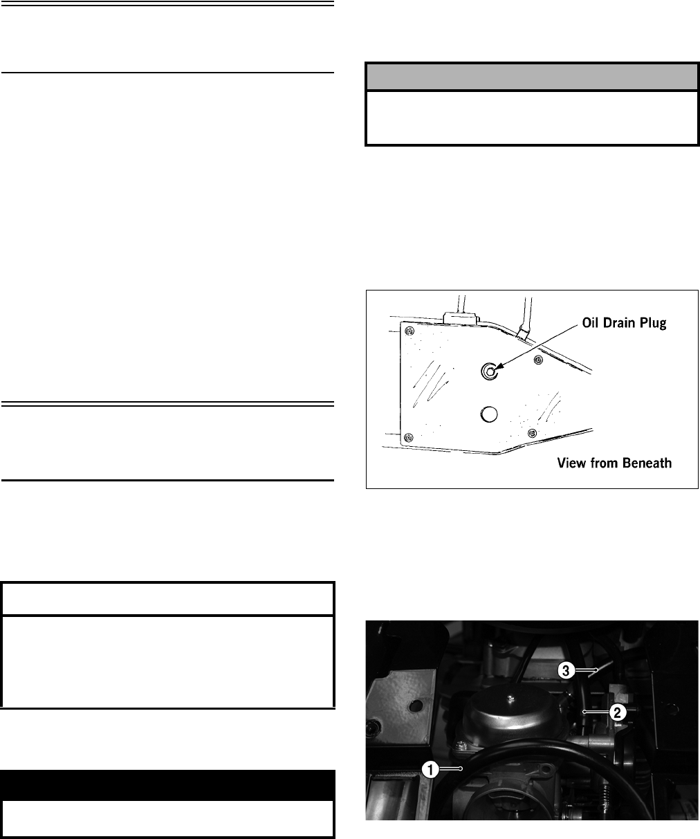
3-76
Table of Contents
(400 — Automatic Transmission)
Removing Engine/Transmission ……………………... 3-76
Top-Side Components……………….…………….…….. 3-79
Removing Top-Side Components …….……………... 3-79
Left-Side Components ……………………….………….. 3-83
Removing Left-Side Components ….…………….….. 3-83
Right-Side Components …………….………….……….. 3-85
Removing Right-Side Components…..……………... 3-86
Center Crankcase Components……….……………... 3-90
Separating Crankcase Halves………….……………... 3-90
Disassembling Crankcase Half ……………………….. 3-91
Servicing Components………..……………..………….. 3-93
Assembling Crankcase Half ………………..………… 3-112
Joining Crankcase Halves……………….………….… 3-115
Installing Right-Side Components…….……………. 3-116
Installing Left-Side Components …………….……… 3-119
Installing Top-Side Components ………………….… 3-121
Installing Engine/Transmission ……………………… 3-126
Removing Engine/
Transmission
Many service procedures can be performed without
removing the engine/transmission from the frame.
Closely observe the note introducing each sub-sec-
tion for this important information.
Secure the ATV on a support stand to elevate the
wheels.
1. Remove the seat; then remove the battery
cover/tool tray.
2. Remove the negative cable from the battery;
then remove the positive cable. Remove the bat-
tery vent hose; then remove the battery.
3. Remove the front and rear racks (see Section 8).
4. Remove the storage compartment and the steer-
ing post access panel (see Section 8).
5. Drain the oil from beneath the engine/transmis-
sion.
733-441A
6. Remove the front and rear fender panels (see
Section 8).
7. Disconnect the fuel hose (1), carburetor vent
hose (2), and the fuel pump vacuum hose (3)
from the carburetor.
CF178A
8. Disconnect the crankcase vent hose from the air
cleaner housing. Remove the clamp securing the
air intake hose to the carburetor; then remove
the air cleaner housing.
NOTE: The air cleaner intake duct must be
removed prior to removing the air cleaner housing.
AT THIS POINT
If the technician’s objective is to service/replace
left-side cover oil seals (3), front output joint oil
seal (1), rear output joint oil seal (1), and/or the oil
strainer (from beneath the engine/ transmission),
the engine/transmission does not have to be
removed from the frame.
! WARNING
Make sure the ATV is solidly supported on the sup-
port stand to avoid injury.
! CAUTION
Battery acid is harmful if it contacts eyes, skin, or
clothing. Care must be taken whenever handling a
battery.
FOR ARCTIC CAT ATV DISCOUNT PARTS CALL 606-678-9623 OR 606-561-4983
www.mymowerparts.com
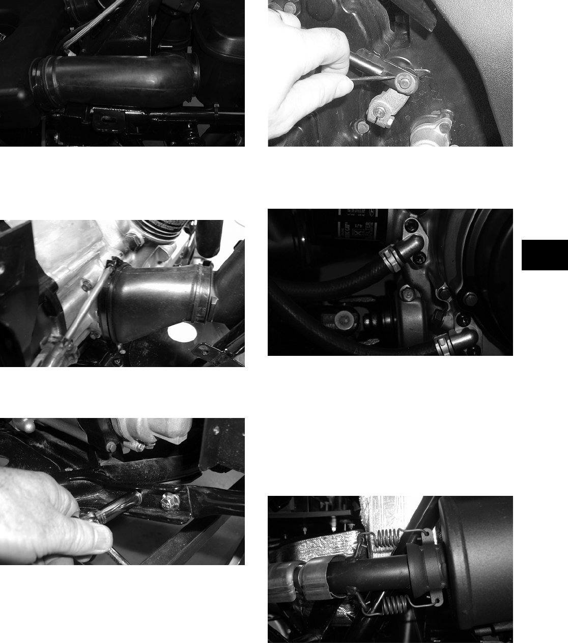
3-77
3
CF181
9. Remove the clamps securing the cooling ducts
to the V-belt housing.
10. Remove the cooling ducts from the V-belt cover.
CD793
11. Remove the cap screws securing the left-side
foot peg to the footrest.
CD781
12. Loosen the clamp securing the carburetor to the
intake; then route the carburetor assembly up
and away from the engine.
13. Remove the E-clip securing the shift rod to the
engine shift arm; then allow the shift rod to hang
by the pivot axle bolt.
AF962
14. Remove the cap screws securing the two oil fit-
tings to the crankcase; then route the hoses away
from the engine. Account for two O-rings.
CF174
NOTE: There will be a substantial amount of oil
draining from the oil hoses when removing. Place
a drain pan beneath the hoses prior to removing
the cap screws.
15. Remove the two cap screws securing the
exhaust pipe to the engine; then remove the
exhaust springs from the muffler at the juncture
in front of the muffler.
CF138
16. Remove the four cap screws securing the rear
output shaft to the transmission; then push the
shaft to the rear as far as possible.
FOR ARCTIC CAT ATV DISCOUNT PARTS CALL 606-678-9623 OR 606-561-4983
www.mymowerparts.com
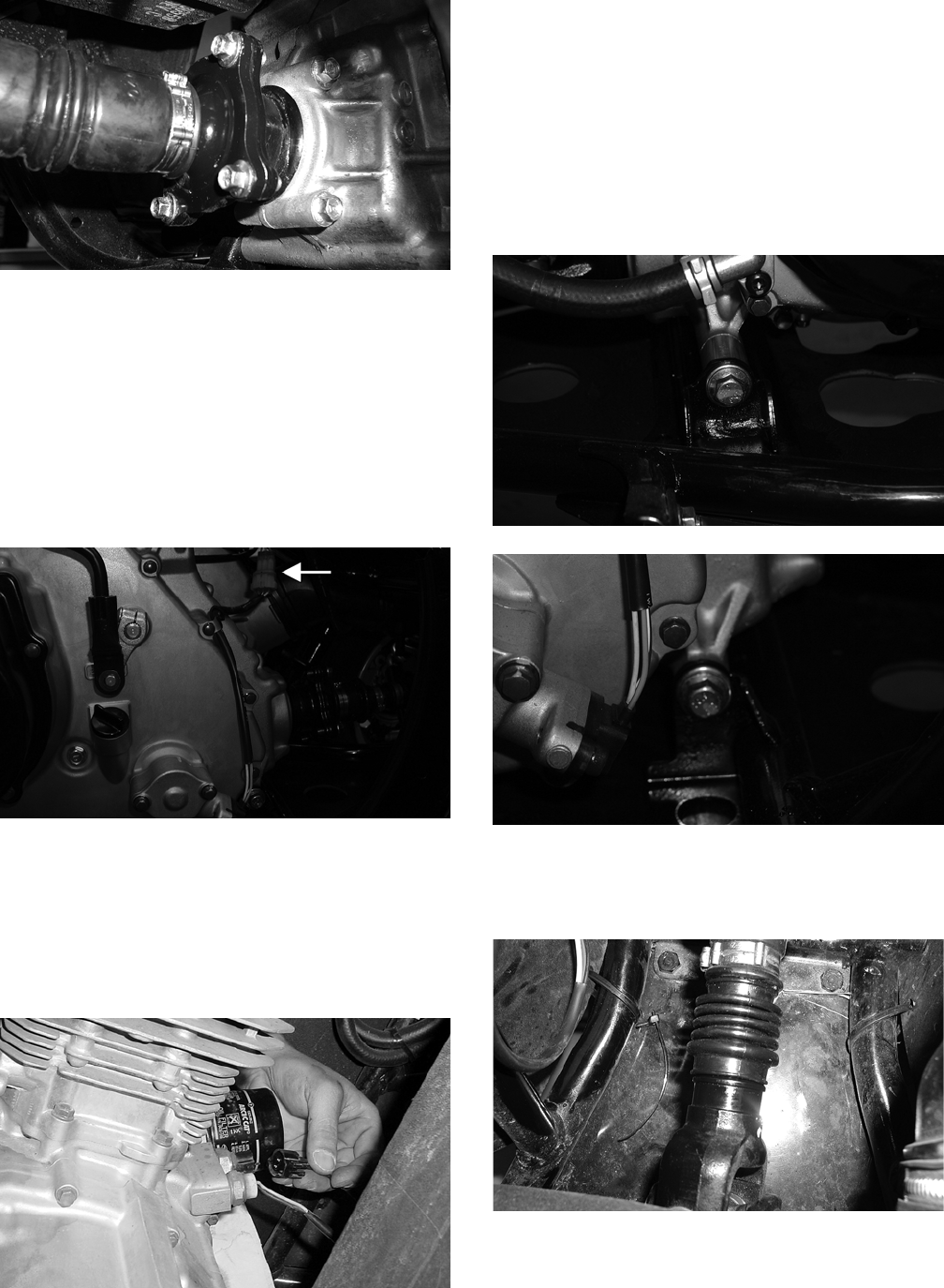
3-78
CD085
NOTE: It is advisable to lock the brake when
loosening the cap screws securing the rear drive-
shaft.
17. Remove the positive cable from the starter
motor and route it out of the way.
18. Disconnect the speed sensor lead from the wir-
ing harness.
CF172A
19. Disconnect the stator-to-rectifier/regulator con-
nector.
20. Remove the temperature sensor wires from the
engine.
NOTE: There are two temperature sensors.
CC939
21. Remove the spark plug wire from the spark
plug.
22. Remove the shift indicator connector from the
main wiring harness.
23. Remove the cap screw securing the engine
ground wire to the engine.
24. Remove the two engine mounting through-bolts.
Account for a spacer on the lower front bolt.
CF193
CF194
25. Slightly raise the front of the engine to disen—
gage the front driveshaft from the front output
yoke.
CD096
FOR ARCTIC CAT ATV DISCOUNT PARTS CALL 606-678-9623 OR 606-561-4983
www.mymowerparts.com
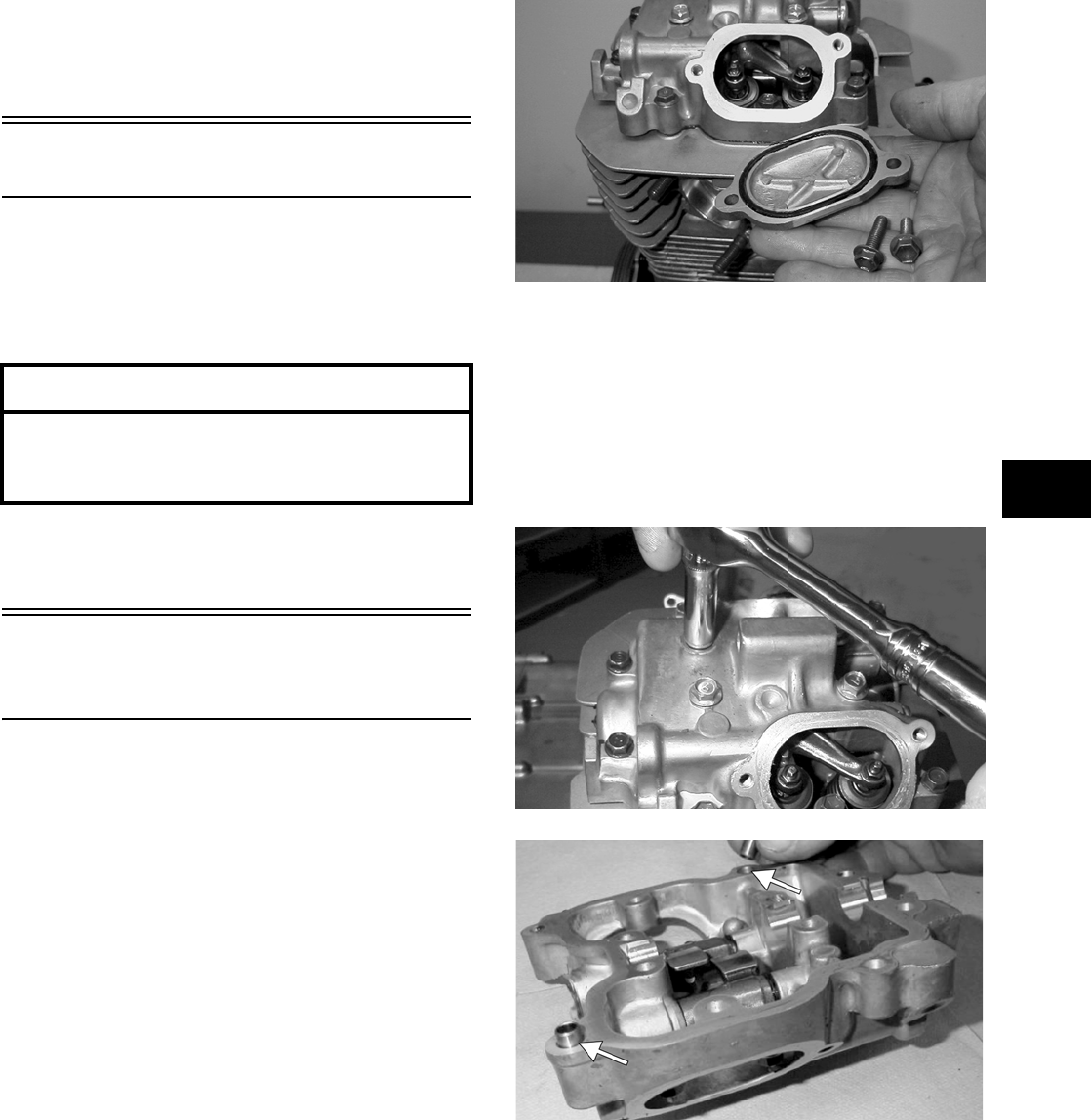
3-79
3
26. Remove the engine from the left side by moving
the engine forward while raising the engine in
the rear and rotating the engine clockwise. The
engine will come out the left side of the frame.
Top-Side Components
NOTE: For efficiency, it is preferable to remove
and disassemble only those components which
need to be addressed and to service only those
components. The technician should use discretion
and sound judgment.
NOTE: The engine/transmission does not have
to removed from the frame for this procedure.
Removing Top-Side
Components
A. Valve Cover
B. Cylinder Head
NOTE: Remove the spark plug and timing
inspection plug; then using the recoil starter,
rotate the crankshaft to top-dead-center of the
compression stroke.
NOTE: Arctic Cat recommends the use of new
gaskets, lock nuts, and seals and lubricating all
internal components when servicing the
engine/transmission.
1. Remove the cap screws securing the two tappet
covers. Remove the two tappet covers. Account
for the O-rings.
MD1264
NOTE: Keep the mounting hardware with the
covers for assembly purposes.
2. Remove the 12 valve cover cap screws. Note the
rubber washers on the four top-side cap screws;
remove the valve cover. Note the orientation of
the cylinder head plug and remove it. Note the
location of the two alignment pins.
MD1261
MD1354A
3. Loosen the cap screw on the end of the cam
chain tensioner; then remove the two Allen-head
screws securing the cam chain tensioner assem-
bly. Remove the tensioner assembly and gasket.
AT THIS POINT
To service any one specific component, only
limited disassembly of components may be
necessary. Note the AT THIS POINT information in
each sub-section.
FOR ARCTIC CAT ATV DISCOUNT PARTS CALL 606-678-9623 OR 606-561-4983
www.mymowerparts.com
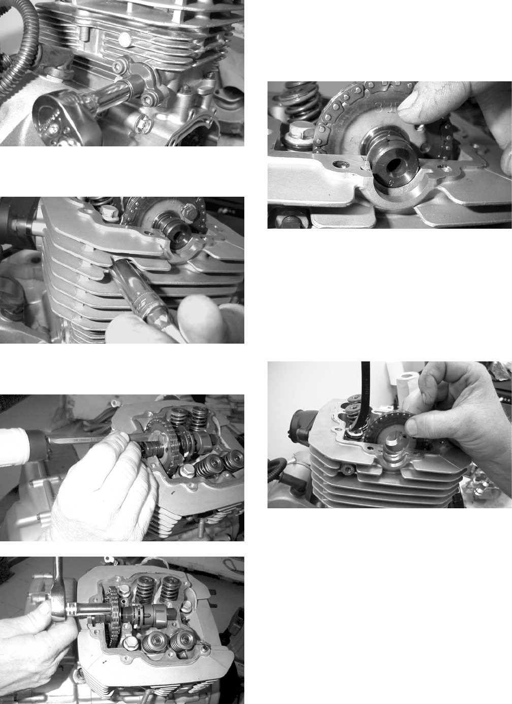
3-80
MD1245
4. Remove the cam chain tensioner pivot cap
screw and washer.
MD1251
5. Bend the washer tabs and remove the two cap
screws securing the sprocket to the camshaft.
MD1136
MD1137
6. Using an awl, rotate the C-ring in its groove
until it is out of the cylinder head; then remove
the C-ring.
NOTE: Care should be taken not to drop the
C-ring down into the crankcase.
MD1131
7. Noting the timing marks for installing purposes,
drop the sprocket off the camshaft. While hold-
ing the cam chain, slide the sprocket and cam-
shaft out of the cylinder head. Account for an
alignment pin.
NOTE: Loop the chain over the cylinder and
secure it with a wire to keep it from falling into the
crankcase.
MD1132
8. Remove the cam chain tensioner by lifting it
from the chain cavity; then remove the two
lower nuts securing the cylinder head to the cyl-
inder, one in front and one in rear.
FOR ARCTIC CAT ATV DISCOUNT PARTS CALL 606-678-9623 OR 606-561-4983
www.mymowerparts.com
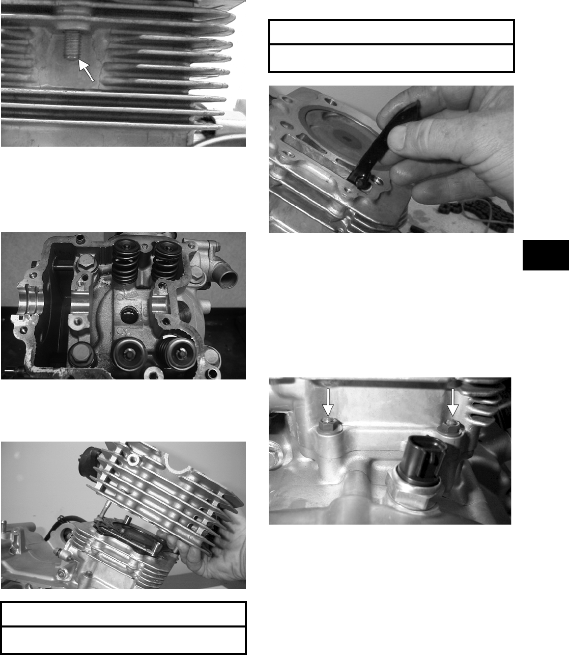
3-81
3
MD1192
9. Remove the four cylinder head cap screws and
washers. Note that the two cap screws on the
right side of the cylinder head nearest the cam
sprocket are longer than the two cap screws on
the left (spark plug) side.
CD211
10. Remove the cylinder head from the cylinder,
remove the gasket, and account for two align-
ment pins.
MD1163
11. Remove the cam chain guide.
MD1173
C. Cylinder
D. Piston
NOTE: Steps 1-11 in the preceding sub-section
must precede this procedure.
12. Remove the two nuts securing the right side of
the cylinder to the right-side crankcase half.
Account for the washers.
MD1226A
13. Lift the cylinder off the crankcase taking care
not to allow the piston to drop against the crank-
case. Account for the gasket and two alignment
pins.
AT THIS POINT
To service valves and cylinder head, see
Servicing Top-Side Components sub-section.
AT THIS POINT
To inspect cam chain guide, see Servicing
Top-Side Components sub-section.
FOR ARCTIC CAT ATV DISCOUNT PARTS CALL 606-678-9623 OR 606-561-4983
www.mymowerparts.com
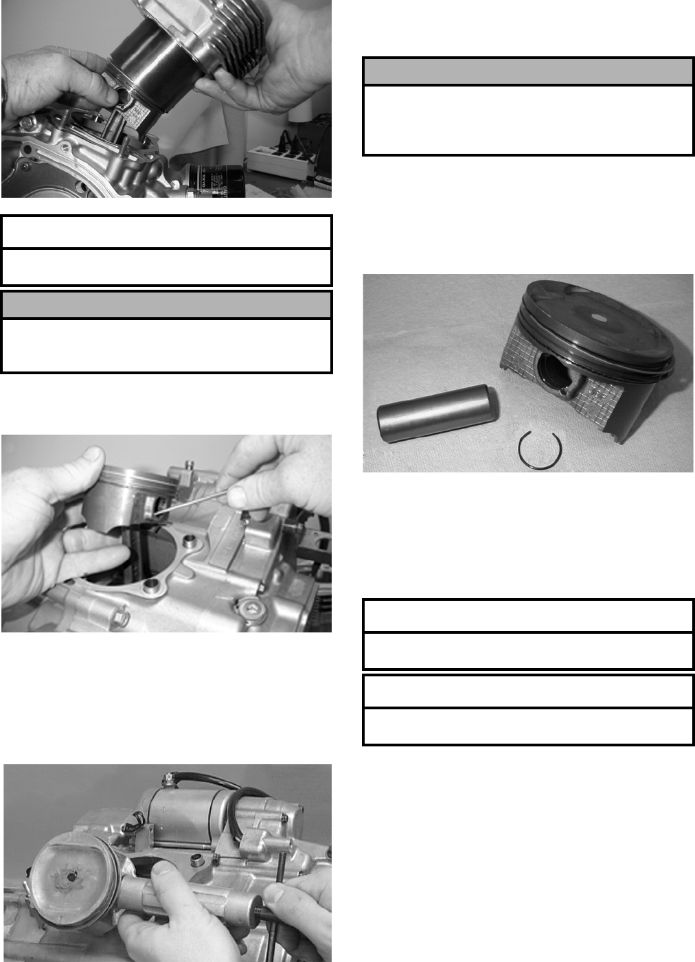
3-82
MD1214
14. Using an awl, remove one piston-pin circlip.
Take care not to drop it into the crankcase.
MD1213
15. Using Piston Pin Puller (p/n 0644-328), remove
the piston pin. Account for the opposite-side cir-
clip. Remove the piston.
NOTE: It is advisable to remove the oppo-
site-side circlip prior to using the puller.
MD1219
NOTE: Support the connecting rod with rubber
bands to avoid damaging the rod or install a con-
necting rod holder.
NOTE: If the existing rings will not be replaced
with new rings, note the location of each ring for
proper installation. When replacing with new rings,
replace as a complete set only. If the piston rings
must be removed, remove them in this sequence.
MD1211
A. Starting with the top ring, slide one end of the
ring out of the ring-groove.
B. Remove each ring by working it toward the
dome of the piston while rotating it out of the
groove.
AT THIS POINT
To service cylinder, see Servicing Top-Side
Components sub-section.
! CAUTION
When removing the cylinder, be sure to support the
piston to prevent damage to the crankcase and pis-
ton.
! CAUTION
Do not allow the connecting rod to go down inside
the crankcase. If the rod is down inside the crank-
case and the crankshaft is rotated, severe damage
will result.
AT THIS POINT
To service piston, see Servicing Top-Side
Components sub-section.
AT THIS POINT
To service center crankcase components only,
proceed to Removing Left-Side Components.
FOR ARCTIC CAT ATV DISCOUNT PARTS CALL 606-678-9623 OR 606-561-4983
www.mymowerparts.com
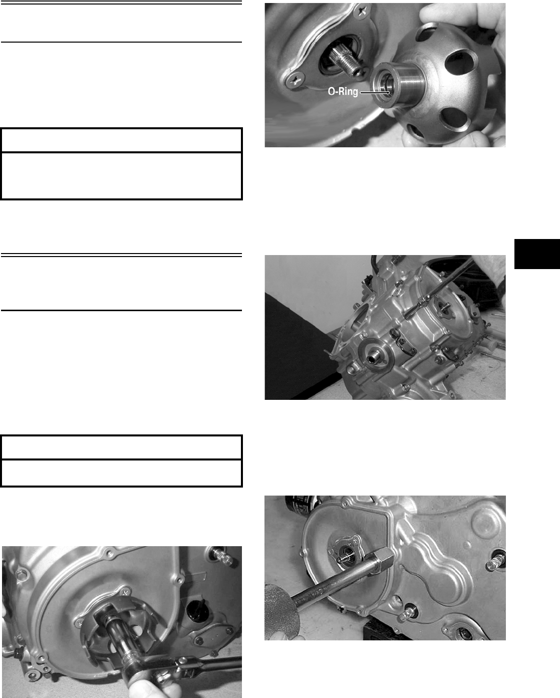
3-83
3
Left-Side Components
NOTE: For efficiency, it is preferable to remove
and disassemble only those components which
need to be addressed and to service only those
components. The technician should use discretion
and sound judgment.
NOTE: The engine/transmission does not have
to be removed from the frame for this procedure.
Removing Left-Side
Components
A. Recoil Starter
B. Starter Cup
C. Cover/Stator Assembly
1. Remove the four recoil starter cover cap screws.
Remove the recoil starter assembly noting the
location of the single washer. Note the condition
of the recoil cover gasket. Replace if damaged.
2. Remove the flange nut securing the starter cup
to the crankshaft; then remove the starter cup.
Account for the O-ring inside the cup.
MD1303
MD1304
3. Lay the engine/transmission on its right side.
Remove the 15 left-side cover-to-crankcase
mounting cap screws noting the location of the 8
mm cap screw with the washer near the middle
of the left-side cover. Keep the differ-
ent-lengthed 6 mm cap screws in order for
installing purposes.
MD1186
4. Using Side Case Puller (p/n 0644-262) and the 6
mm adapter, remove the left-side cover w/stator
assembly. Note the condition of the gasket.
Replace if necessary. Account for the two align-
ment pins and the position of the shifter bracket
for installing purposes.
CC946
AT THIS POINT
To service any one specific component, only
limited disassembly of components may be
necessary. Note the AT THIS POINT information in
each sub-section.
AT THIS POINT
To service the recoil starter, see Servicing
Left-Side Components sub-section.
FOR ARCTIC CAT ATV DISCOUNT PARTS CALL 606-678-9623 OR 606-561-4983
www.mymowerparts.com
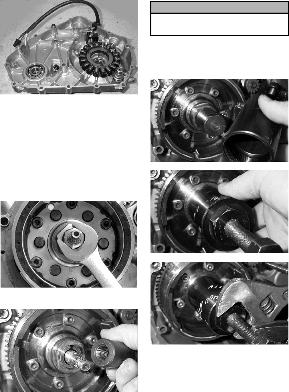
3-84
MD1188
NOTE: Inspect the inside of the left-side cover
for any shaft washers that may have come off with
the cover. Make sure they are returned to their
respective shafts and that the starter idler gear
spacer is on the shaft or in the cover.
D. Rotor/Flywheel
E. Starter Motor
NOTE: Steps 1-4 in the preceding sub-section
must precede this procedure.
5. Remove the rotor/flywheel nut.
MD1194
6. Install the crankshaft protector.
MD1365
7. Using Magneto Rotor Remover (p/n 0444-075),
break the rotor/flywheel assembly loose from
the crankshaft. Remove the remover, the crank-
shaft protector, the rotor/flywheel, and the
starter clutch gear. Account for the key.
MD1368
MD1369
MD1370
8. Remove the starter idler gear (No. 1) and starter
idler gear (No. 2).
! CAUTION
Care must be taken that the remover is fully
threaded onto the rotor/flywheel or damage may
occur.
FOR ARCTIC CAT ATV DISCOUNT PARTS CALL 606-678-9623 OR 606-561-4983
www.mymowerparts.com
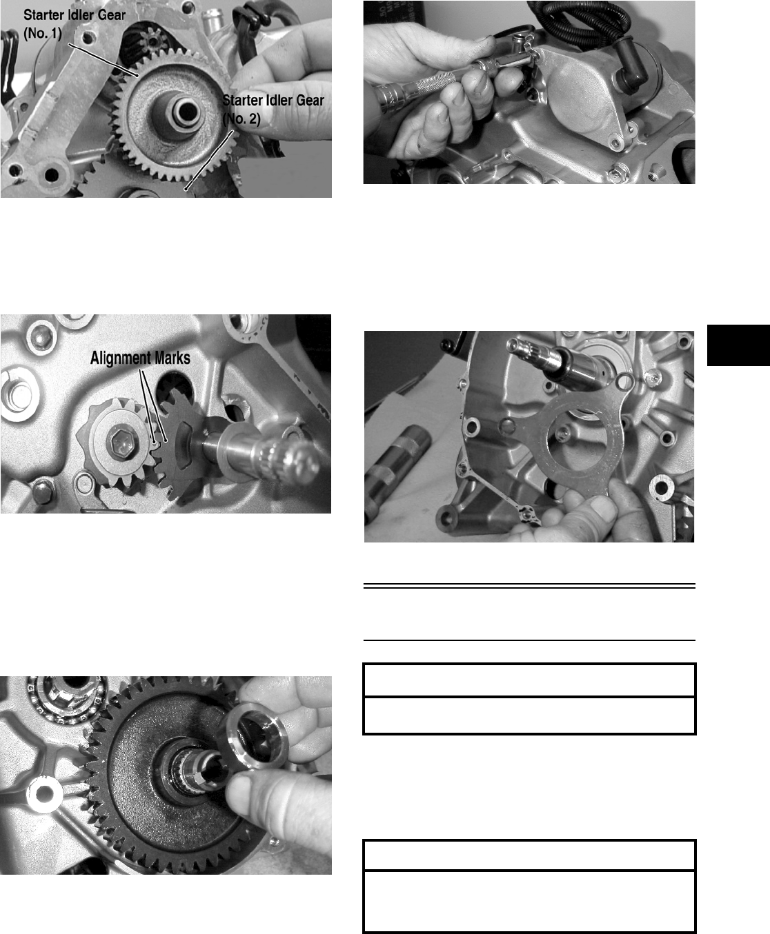
3-85
3
MD1305
9. Remove the gear shift shaft assembly and
washer from the left-side crankcase. Note the
positions of the alignment marks and washer for
installing purposes; then release the cam stopper
spring tension.
MD1239
10. Remove the shift detent cam. Note position of
spacer for installing purposes.
11. Remove the cam stopper assembly.
12. Remove the spacer from the driveshaft noting
the direction of the stepped side for installing
purposes.
MD1224
13. Remove two starter motor cap screws.
MD1078
14. Remove starter motor by tapping lightly with a
mallet.
15. Using an impact screwdriver, remove the three
Phillips-head screws holding the crankshaft
bearing retainer. Remove the crankshaft bearing
retainer.
MD1122
Right-Side Components
NOTE: For efficiency, it is preferable to remove
and disassemble only those components which
need to be addressed and to service only those
components. The technician should use discretion
and sound judgment.
NOTE: The engine/transmission does not have
to be removed from the frame for this procedure.
AT THIS POINT
To service center crankcase components only,
proceed to Removing Right-Side Components.
AT THIS POINT
To service any one specific component, only
limited disassembly of components may be
necessary. Note the AT THIS POINT information
in each sub-section.
FOR ARCTIC CAT ATV DISCOUNT PARTS CALL 606-678-9623 OR 606-561-4983
www.mymowerparts.com
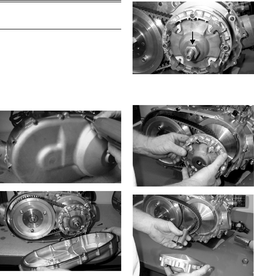
3-86
Removing Right-Side
Components
A. V-Belt Cover
B. Driven Pulley
C. Clutch Cover
1. If the engine is still in the frame, turn the gas
tank valve to the OFF position. Remove the cap
screws securing the right-side V-belt cover to
the clutch cover. Remove the cover. Note the
locations of the long cap screws and the two
wire forms. Account for the gasket and for two
alignment pins.
MD1306
MD1307
2. Mark the movable drive face and the fixed drive
face for installing purposes; then remove the nut
holding the movable drive face onto the crank-
shaft.
MD1033
3. Remove the movable drive face and spacer.
Account for the eight movable drive face rollers
and outer drive face cover.
MD1035
MD1034
FOR ARCTIC CAT ATV DISCOUNT PARTS CALL 606-678-9623 OR 606-561-4983
www.mymowerparts.com
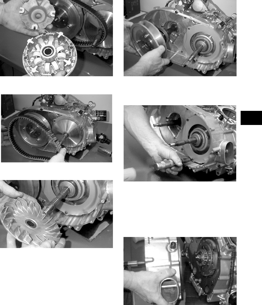
3-87
3
MD1036
4. Remove the V-belt.
MD1118
5. Remove the fixed drive face.
MD1094
6. Remove the nut holding the driven pulley
assembly; then remove the driven pulley assem-
bly.
MD1068
7. Using an impact screwdriver, remove the three
Phillips-head cap screws holding the air intake
plate. Remove the air intake plate.
MD1092
8. Remove the cap screws holding the clutch cover
onto the right-side crankcase half. Note the posi-
tions of the different-lengthed cap screws for
installing purposes.
9. Using a rubber mallet, loosen the clutch cover;
then pull it away from the right-side crankcase
half. Account for two alignment pins and gasket.
MD1115
FOR ARCTIC CAT ATV DISCOUNT PARTS CALL 606-678-9623 OR 606-561-4983
www.mymowerparts.com
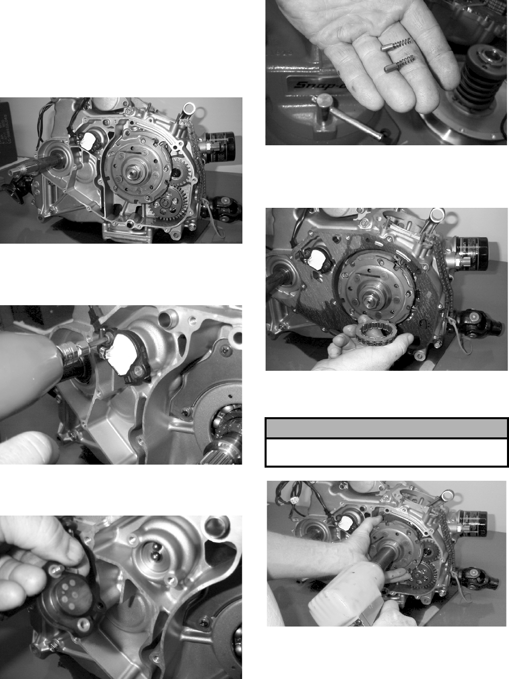
3-88
D. Gear Position Switch
E. Centrifugal Clutch Assembly
F. Oil Pump Drive Gear
G. Oil Pump Driven Gear
NOTE: Steps 1-9 in the preceding sub-section
must precede this procedure.
MD1072
10. Remove the cap screws holding the gear posi-
tion indicator switch onto the right-side crank-
case half.
MD1041
11. Remove the gear position indicator switch.
Account for two contact pins and two springs.
MD1040
MD1043
12. Remove the one-way sprag clutch noting the
direction of the green dot or the stamp tag OUT-
SIDE for installing purposes.
MD1286
13. Remove the left-hand threaded nut holding the
centrifugal clutch assembly.
MD1014
! CAUTION
Care must be taken when removing the nut; it has
“left-hand” threads.
FOR ARCTIC CAT ATV DISCOUNT PARTS CALL 606-678-9623 OR 606-561-4983
www.mymowerparts.com
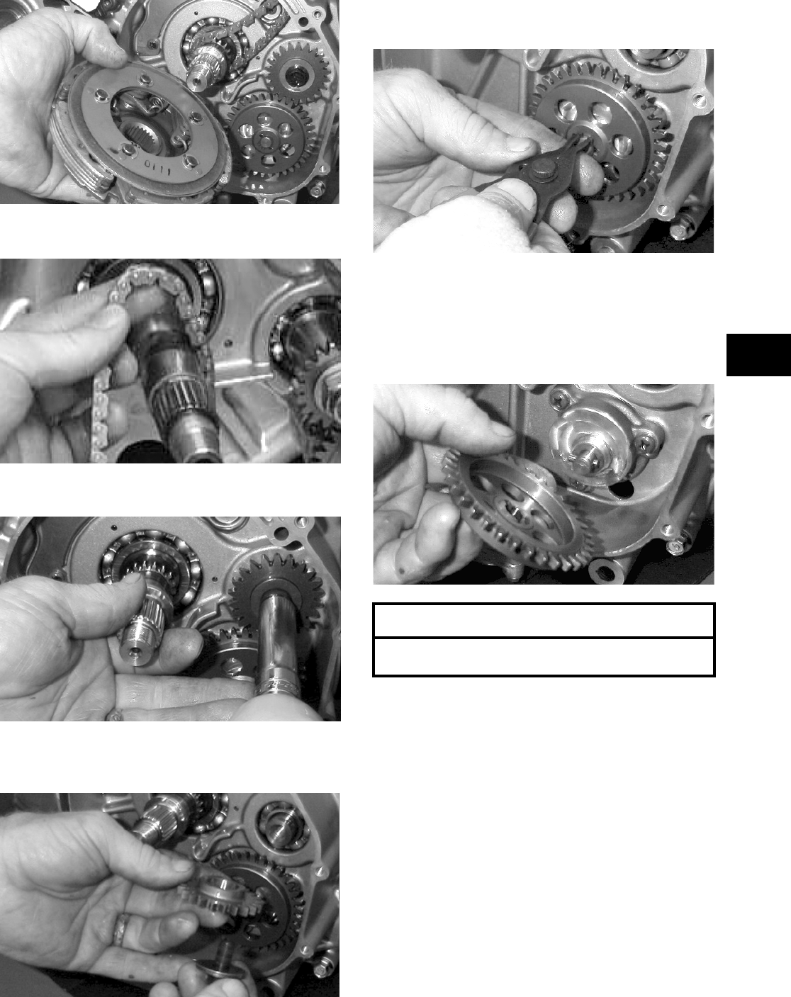
3-89
3
MD1016
14. Remove the cam chain.
MD1335
15. Remove the oil pump drive gear cap screw.
MD1018
16. Remove oil pump drive gear. Account for the
pin.
MD1017
17. Remove the snap ring holding the oil pump
driven gear.
MD1019
NOTE: Always use a new snap ring when install-
ing the oil pump driven gear.
18. Remove oil pump driven gear. Account for the
pin.
MD1020
H. Oil Pump/Oil Strainer
NOTE: Steps 1-18 in the preceding sub-sections
must precede this procedure.
19. Remove three Phillips-head screws holding the
oil pump and remove the oil pump. Account for
two alignment pins.
AT THIS POINT
To service clutch components, see Servicing
Right-Side Components sub-section.
FOR ARCTIC CAT ATV DISCOUNT PARTS CALL 606-678-9623 OR 606-561-4983
www.mymowerparts.com
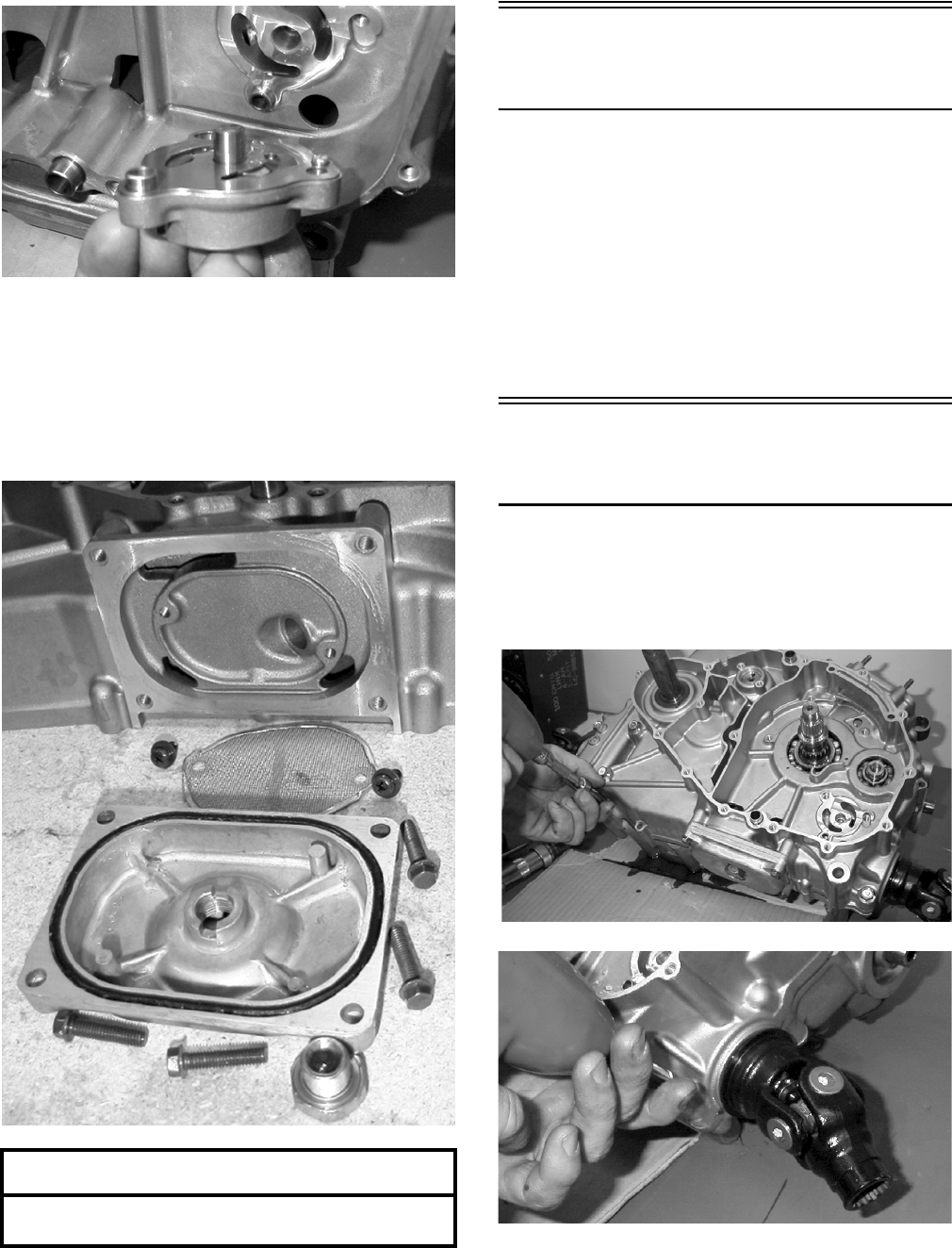
3-90
MD1060
20. Remove the four cap screws securing the oil
strainer cover; then remove the Phillips-head
screws securing the oil strainer. Account for the
O-ring.
NOTE: Note the directional arrow for installing
purposes.
MD1207
Center Crankcase
Components
NOTE: This procedure cannot be done with the
engine/transmission in the frame. Complete
Removing procedures for Top-Side, Left-Side, and
Right-Side must precede this procedure.
NOTE: For efficiency, it is preferable to remove
and disassemble only those components which
need to be addressed and to service only those
components. The technician should use discretion
and sound judgment.
Separating Crankcase
Halves
1. Remove the left-side and right-side cap screws
securing the crankcase halves noting the posi-
tion of the different-sized cap screws for joining
purposes.
MD1006
MD1012
2. Using Crankcase Separator/Crankshaft Remover
(p/n 0444-009) and tapping lightly with a rubber
mallet, separate the crankcase halves. Account
for two alignment pins.
AT THIS POINT
To service center crankcase components only,
proceed to Separating Crankcase Halves.
FOR ARCTIC CAT ATV DISCOUNT PARTS CALL 606-678-9623 OR 606-561-4983
www.mymowerparts.com
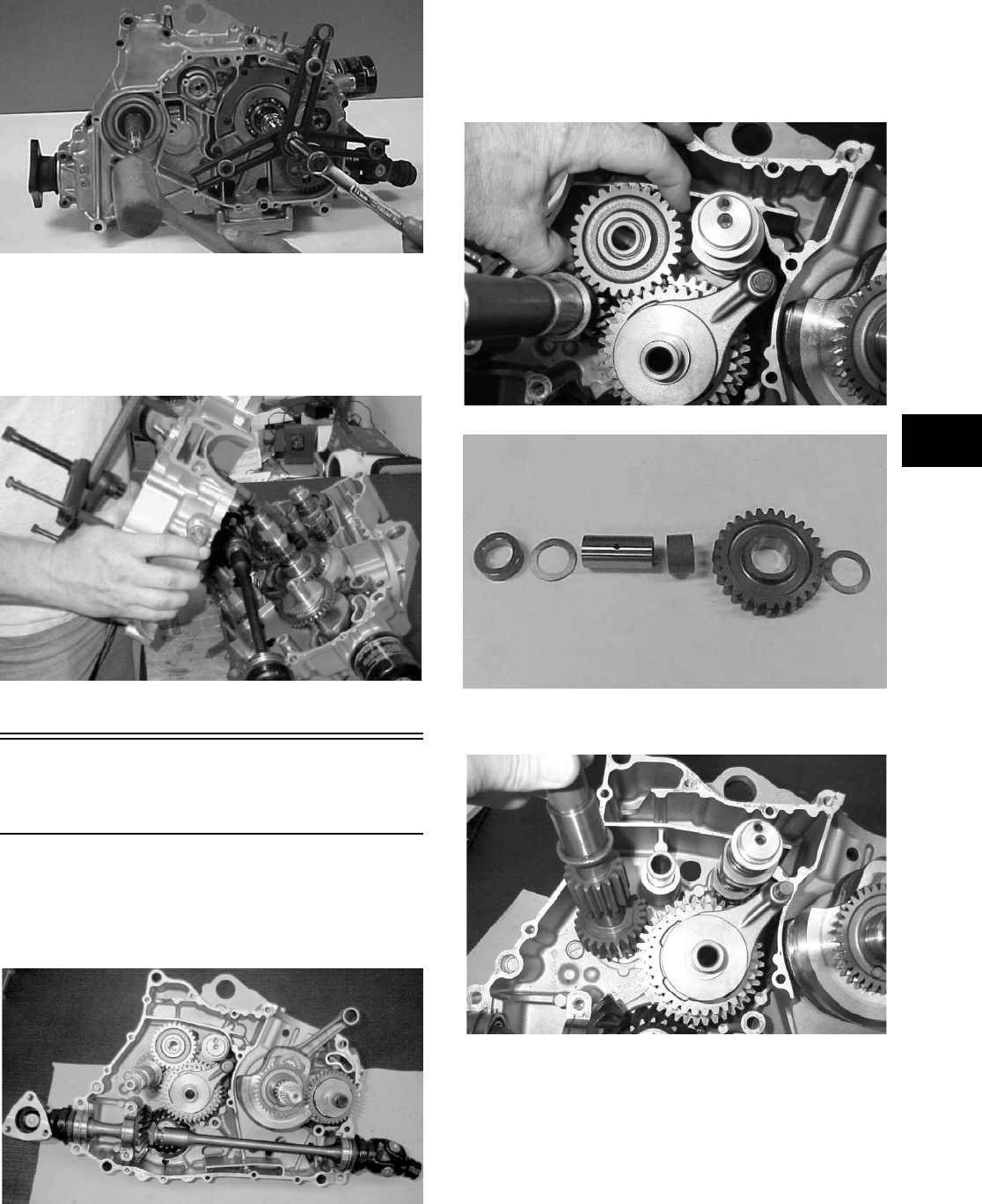
3-91
3
CC869
NOTE: To keep the shaft/gear assemblies intact
for identification, tap the shafts toward the
left-side crankcase half when separating the
halves.
MD1313
Disassembling
Crankcase Half
1. Remove the secondary and primary driveshaft
assemblies. Account for the bearing alignment
C-ring on the bearing boss next to the pinion
gear.
MD1317
NOTE: Note the location of the bearing align-
ment pin on the secondary output shaft.
2. Remove the reverse idler gear, spacer, and
sleeve. Account for the washers.
MD1325
CC870
3. Remove the driveshaft.
MD1326
4. Remove the shift fork shaft and the outer shift
fork.
FOR ARCTIC CAT ATV DISCOUNT PARTS CALL 606-678-9623 OR 606-561-4983
www.mymowerparts.com
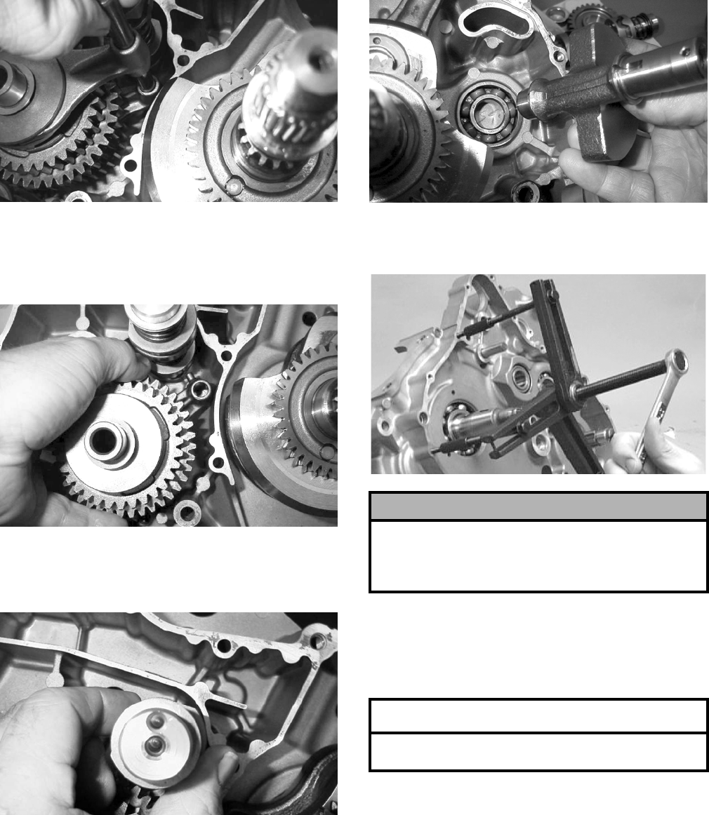
3-92
MD1327
5. Remove snap ring and gear from the output side
of the gear cluster. Remove the gear cluster and
the inner shift fork together. Account for snap
ring, gear, and washer.
MD1328
6. Noting the position of the two holes on the end,
remove the shift cam assembly. Account for
inner and outer washers.
MD1329
7. Remove the counterbalance gear. Account for
the key.
8. Remove the counterbalance shaft.
MD1024
9. Using Crankcase Separator/Crankshaft Remover
(p/n 0444-009), remove the crankshaft.
MD1330
10. Remove the secondary drive gear/secondary
driven gear retaining nut. From inside the crank—
case using a rubber mallet, drive out the output
shaft assembly. Account for the output shaft, a
shim, a washer, and the nut.
! CAUTION
Do not remove the remaining output shaft assembly
unless absolutely necessary. If the shaft is removed,
the shaft nut must be replaced with a new one and
the shaft must be re-shimmed.
AT THIS POINT
To service crankshaft assembly, see Servicing
Center Crankcase Components sub-section.
FOR ARCTIC CAT ATV DISCOUNT PARTS CALL 606-678-9623 OR 606-561-4983
www.mymowerparts.com
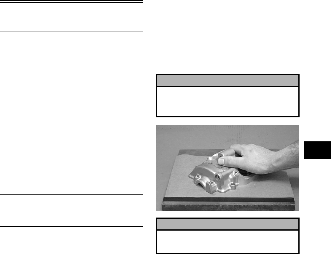
3-93
3
Table of Contents
(Servicing Components)
NOTE: Critical engine/transmission specifica-
tions are located at the beginning of this section.
Servicing Top-Side Components ……..……………... 3-93
Valve Assembly ………………….…………….……….. 3-93
Piston Assembly ……….…………….…………….….. 3-96
Cylinder/Cylinder Head Assembly ………………… 3-98
Servicing Left-Side Components .…………….…… 3-101
Recoil Starter ………………………….…………….… 3-101
Servicing Right-Side Components ………………… 3-104
Inspecting Centrifugal Clutch Shoe ……………. 3-104
Inspecting Centrifugal Clutch Housing ………… 3-104
Inspecting Primary One-Way Drive …………..… 3-104
Inspecting Oil Pump ..…………….…………….…… 3-105
Driven Pulley Assembly …………………..………… 3-105
Servicing Center Crankcase Components ……… 3-109
Secondary Gears ………………….………….……… 3-109
Crankshaft Assembly ……………….…………….… 3-110
Countershaft …………….…………….…………….… 3-111
Crank Balancer Driven Gear………………….…… 3-112
Servicing Top-Side
Components
NOTE: Whenever a part is worn excessively,
cracked, or damaged in any way, replacement is
necessary.
VALVE ASSEMBLY
When servicing valve assembly, inspect valve seats,
valve stems, valve faces, and valve stem ends for
pits, burn marks, or other signs of abnormal wear.
NOTE: Whenever a valve is out of tolerance, it
must be replaced.
Cleaning/Inspecting Valve Cover
NOTE: If the valve cover cannot be trued, the cyl-
inder head assembly must be replaced.
1. Wash the valve cover in parts-cleaning solvent.
2. Place the valve cover on the Surface Plate (p/n
0644-016) covered with #400 grit wet-or-dry
sandpaper. Using light pressure, move the valve
cover in a figure eight motion. Inspect the seal-
ing surface for any indication of high spots. A
high spot can be noted by a bright metallic fin-
ish. Correct any high spots before assembly by
continuing to move the valve cover in a figure
eight motion until a uniform bright metallic fin-
ish is attained.
CC130D
Removing Valves
NOTE: Keep all valves and valve components as
a set. Note the original location of each valve set
for use during installation. Return each valve set to
its original location during installation.
1. Using a valve spring compressor, compress the
valve springs and remove the valve cotters.
Account for an upper spring retainer.
! CAUTION
Do not remove an excessive amount of the sealing
surface or damage to the camshaft will result.
Always check camshaft clearance when resurfacing
the valve cover.
! CAUTION
Water or parts-cleaning solvent must be used in
conjunction with the wet-or-dry sandpaper or dam-
age to the sealing surface may result.
FOR ARCTIC CAT ATV DISCOUNT PARTS CALL 606-678-9623 OR 606-561-4983
www.mymowerparts.com
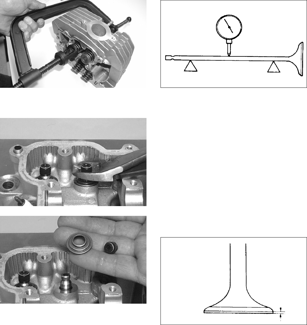
3-94
CC994
2. Remove the valve seal and the lower remaining
spring seat. Discard the valve seal.
CC134D
CC136D
NOTE: The valve seals must be replaced.
3. Remove the valve springs; then invert the cylin-
der head and remove the valves.
Measuring Valve Stem Runout
1. Support each valve stem end with the V Blocks
(p/n 0644-022); then check the valve stem
runout using a dial indicator.
ATV-1082
2. Maximum runout must not exceed specifica-
tions.
Measuring Valve Stem Outside
Diameter
1. Using a micrometer, measure the valve stem
outside diameter.
2. Acceptable diameter range (intake valve) must
be within specifications.
3. Acceptable diameter range (exhaust valve) must
be within specifications.
Measuring Valve Face/Seat Width
1. Using a micrometer, measure the width of the
valve face.
ATV-1004
2. Acceptable width range must be within specifi-
cations.
Measuring Valve Face Radial
Runout
1. Mount a dial indicator on the surface plate; then
place the valve stem on a set of V blocks.
2. Position the dial indicator contact point on the
outside edge of the valve face; then zero the
indicator.
FOR ARCTIC CAT ATV DISCOUNT PARTS CALL 606-678-9623 OR 606-561-4983
www.mymowerparts.com
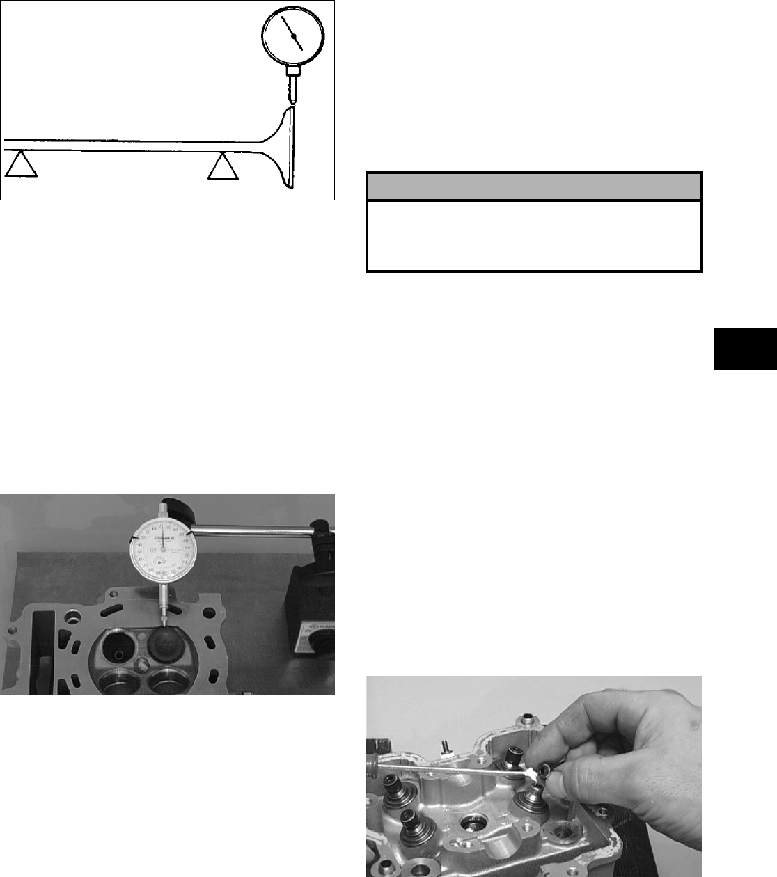
3-95
3
ATV1082A
3. Rotate the valve in the V blocks.
4. Maximum runout must not exceed specifica-
tions.
Measuring Valve Guide/Valve Stem
Deflection (Wobble Method)
1. Mount a dial indicator and base on the surface
plate; then place the cylinder head on the surface
plate.
2. Install the valve into the cylinder head; then
position the dial indicator contact point against
the outside edge of the valve face. Zero the indi-
cator.
CC131D
3. Push the valve from side to side; then from top
to bottom.
4. Maximum “wobble” deflection must not exceed
specifications.
Measuring Valve Guide
(Inside Diameter)
1. Insert a snap gauge 1/2 way down into each
valve guide bore; then remove the gauge and
measure it with a micrometer.
2. Acceptable inside diameter range must be
within specifications.
3. If a valve guide is out of tolerance, it must be
replaced.
Servicing Valves/Valve
Guides/Valve Seats
If valves, valve guides, or valve seats require servic-
ing or replacement, Arctic Cat recommends that the
components be taken to a qualified machine shop
for servicing.
Measuring Rocker Arm
(Inside Diameter)
1. Using a dial calipers, measure the inside diame-
ter of the rocker arm.
2. Acceptable inside diameter range must be
within specifications.
Measuring Rocker Arm Shaft
(Outside Diameter)
1. Using a micrometer, measure the outside diame-
ter of the rocker arm shaft.
2. Acceptable outside diameter range must be
within specifications.
Installing Valves
1. Apply grease to the inside surface of the valve
seals; then place a lower spring seat and valve
guide seal over each valve guide.
CC144D
2. Insert each valve into its original valve location.
3. Install the valve springs with the painted end of
the spring facing away from the cylinder head.
! CAUTION
If valves are discolored or pitted or if the seating
surface is worn, the valve must be replaced. Do not
attempt to grind the valves or severe engine damage
may occur.
FOR ARCTIC CAT ATV DISCOUNT PARTS CALL 606-678-9623 OR 606-561-4983
www.mymowerparts.com
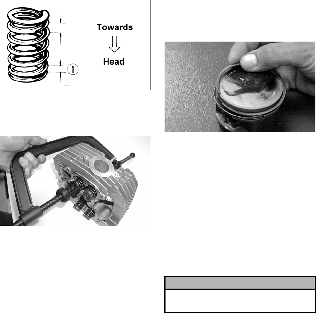
3-96
NOTE: If the paint is not visible, install the ends
of the springs with the closest wound coils toward
the head.
ATV-1011A
4. Place a spring retainer over the valve springs;
then using the valve spring compressor, com-
press the valve springs and install the valve cot-
ters.
CC994
PISTON ASSEMBLY
NOTE: Whenever a piston, rings, or pin are out
of tolerance, they must be replaced.
Cleaning/Inspecting Piston
1. Using a non-metallic carbon removal tool,
remove any carbon buildup from the dome of
the piston.
2. Inspect the piston for cracks in the piston pin,
dome, and skirt areas.
3. Inspect the piston for seizure marks or scuffing.
Repair with #400 grit wet-or-dry sandpaper and
water or honing oil.
NOTE: If scuffing or seizure marks are too deep
to correct with the sandpaper, replace the piston.
4. Inspect the perimeter of each piston for signs of
excessive “blowby.” Excessive “blowby” indi-
cates worn piston rings or an out-of-round cylin-
der.
Removing Piston Rings
1. Starting with the top ring, slide one end of the
ring out of the ring-groove.
CC400D
2. Remove each ring by working it toward the
dome of the piston while rotating it out of the
groove.
NOTE: If the existing rings will not be replaced
with new ones, note the location of each ring for
proper installation. When installing new rings,
install as a complete set only.
Cleaning/Inspecting Piston Rings
1. Take an old piston ring and snap it into two
pieces; then grind the end of the old ring to a 45°
angle and to a sharp edge.
2. Using the sharpened ring as a tool, clean carbon
from the ring-grooves. Be sure to position the
ring with its tapered side up.
Measuring Piston-Ring End Gap
(Installed)
1. Place each piston ring in the wear portion of the
cylinder. Use the piston to position each ring
squarely in the cylinder.
2. Using a feeler gauge, measure each piston-ring
end gap. Acceptable ring end gap must not
exceed specifications.
! CAUTION
Improper cleaning of the ring-grooves by the use
of the wrong type of ring-groove cleaner will
result in severe damage to the piston.
FOR ARCTIC CAT ATV DISCOUNT PARTS CALL 606-678-9623 OR 606-561-4983
www.mymowerparts.com
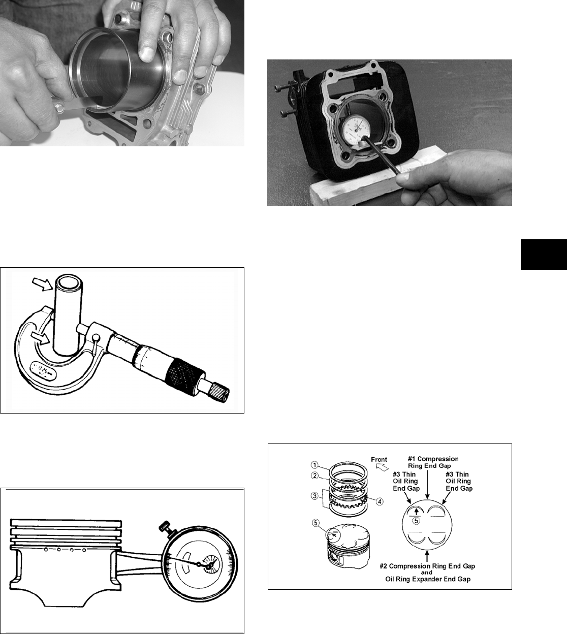
3-97
3
CC995
Measuring Piston Pin (Outside
Diameter) and Piston-Pin Bore
1. Measure the piston pin outside diameter at each
end and in the center. If measurement is not
within specifications, the piston pin must be
replaced.
ATV-1070
2. Insert an inside dial indicator into the piston-pin
bore. The diameter must not exceed specifica-
tions. Take two measurements to ensure accu-
racy.
ATV-1069
Measuring Piston Skirt/
Cylinder Clearance
1. Measure the cylinder front to back in six places.
CC397D
2. Measure the corresponding piston diameter at a
point 15 mm (0.6 in.) above the piston skirt at a
right angle to the piston-pin bore. Subtract this
measurement from the measurement in step 1.
The difference (clearance) must be within speci-
fications.
Installing Piston Rings
1. Install ring expander (4) in the bottom groove of
the piston; then install the thin oil rings (3) over
the expander making sure the expander ends do
not overlap. Stagger the end gaps of the upper
and lower thin oil rings according to the illustra-
tion.
NOTE: Note the direction of the exhaust side of
the piston (5) for correct ring end gap orientation.
ATV-1085B
2. Install the compression rings (1 and 2) so the let-
ter on the top surface of each ring faces the
dome of the piston. Rotate the rings until the
ring end gaps are on directly opposite sides of
the piston according to the illustration.
NOTE: The chrome (silver) ring should be
installed in the top position.
FOR ARCTIC CAT ATV DISCOUNT PARTS CALL 606-678-9623 OR 606-561-4983
www.mymowerparts.com
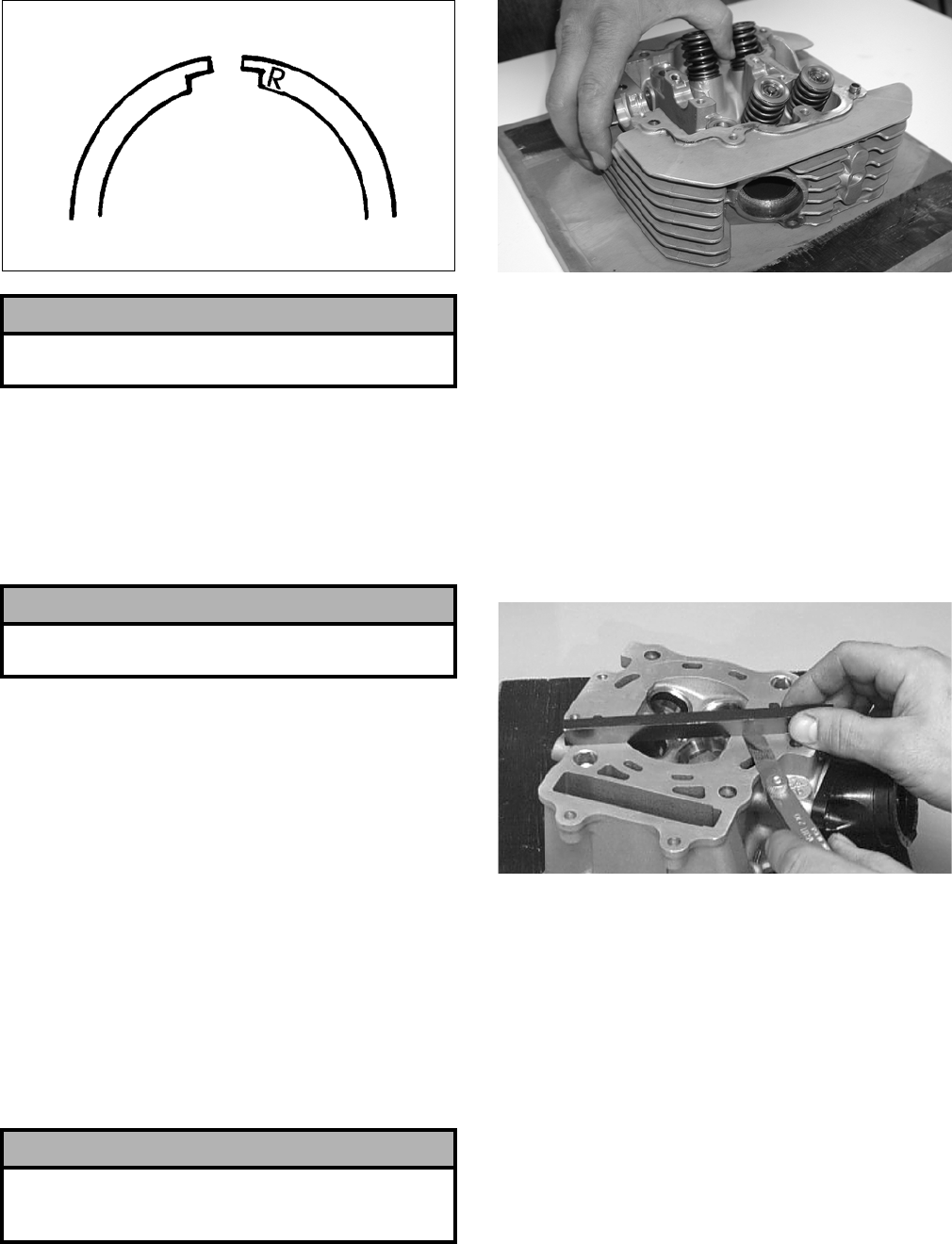
3-98
726-306A
CYLINDER/CYLINDER HEAD
ASSEMBLY
NOTE: If the cylinder/cylinder head assembly
cannot be trued, they must be replaced.
Cleaning/Inspecting Cylinder Head
1. Using a non-metallic carbon removal tool,
remove any carbon buildup from the combus-
tion chamber being careful not to nick, scrape,
or damage the combustion chamber or the seal-
ing surface.
2. Inspect the spark plug hole for any damaged
threads. Repair damaged threads using a
“heli-coil” insert.
3. Place the cylinder head on the surface plate cov-
ered with #400 grit wet-or-dry sandpaper. Using
light pressure, move the cylinder head in a fig-
ure eight motion. Inspect the sealing surface for
any indication of high spots. A high spot can be
noted by a bright metallic finish. Correct any
high spots before assembly by continuing to
move the cylinder head in a figure eight motion
until a uniform bright metallic finish is attained.
CC996
Measuring Cylinder Head
Distortion
1. Remove any carbon buildup in the combustion
chamber.
2. Lay a straightedge across the cylinder head; then
using a feeler gauge, check the distortion factor
between the head and the straightedge.
3. Maximum distortion must not exceed specifica-
tions.
CC141D
Cleaning/Inspecting Cylinder
1. Wash the cylinder in parts-cleaning solvent.
2. Inspect the cylinder for pitting, scoring, scuff-
ing, warpage, and corrosion. If marks are found,
repair the surface using a cylinder hone (see
Honing Cylinder in this sub-section).
3. Place the cylinder on the surface plate covered
with #400 grit wet-or-dry sandpaper. Using light
pressure, move the cylinder in a figure eight
motion. Inspect the sealing surface for any indi-
cation of high spots. A high spot can be noted by
a bright metallic finish. Correct any high spots
before assembly by continuing to move the cyl-
inder in a figure eight motion until a uniform
bright metallic finish is attained.
! CAUTION
Incorrect installation of the piston rings will result in
engine damage.
! CAUTION
The cylinder head studs must be removed for this
procedure.
! CAUTION
Water or parts-cleaning solvent must be used in
conjunction with the wet-or-dry sandpaper or dam-
age to the sealing surface may result.
FOR ARCTIC CAT ATV DISCOUNT PARTS CALL 606-678-9623 OR 606-561-4983
www.mymowerparts.com
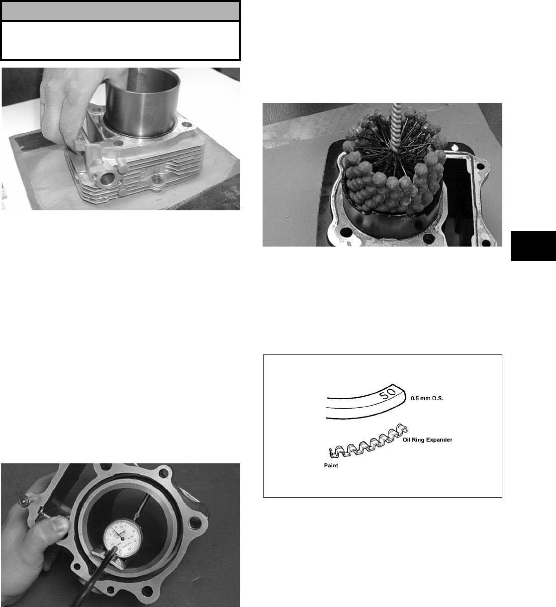
3-99
3
CC997
Inspecting Cam Chain Guide
1. Inspect cam chain guide for cuts, tears, breaks,
or chips.
2. If the chain guide is damaged, it must be
replaced.
Honing Cylinder
1. Using a slide gauge and a dial indicator or a
snap gauge, measure the cylinder bore diameter
in three locations from top to bottom and again
from top to bottom at 90° from the first mea-
surements for a total of six measurements. The
trueness (out-of-roundness) is the difference
between the highest and lowest reading. Maxi-
mum trueness (out-of-roundness) must not
exceed specifications.
CC127D
2. Wash the cylinder in parts-cleaning solvent.
3. Inspect the cylinder for pitting, scoring, scuff-
ing, and corrosion. If marks are found, repair the
surface using a ball hone.
NOTE: To produce the proper 60° cross-hatch
pattern, use a low RPM drill (600 RPM) at the rate
of 30 strokes per minute. If honing oil is not avail-
able, use a lightweight petroleum-based oil. Thor-
oughly clean cylinder after honing using soap and
hot water. Dry with compressed air; then immedi-
ately apply oil to the cylinder bore. If the bore is
severely damaged or gouged, replace the cylinder.
CC390D
4. If any measurement exceeds the limit, bore the
cylinder and install an oversized piston or
replace the cylinder.
NOTE: Oversized piston and rings are available.
The oversized piston and rings are marked for
identification.
ATV-1068A
Measuring Camshaft Runout
NOTE: If the camshaft is out of tolerance, it must
be replaced.
1. Place the camshaft on a set of V blocks; then
position the dial indicator contact point against
the shaft and zero the indicator.
! CAUTION
Water or parts-cleaning solvent must be used in
conjunction with the wet-or-dry sandpaper or dam-
age to the sealing surface may result.
FOR ARCTIC CAT ATV DISCOUNT PARTS CALL 606-678-9623 OR 606-561-4983
www.mymowerparts.com
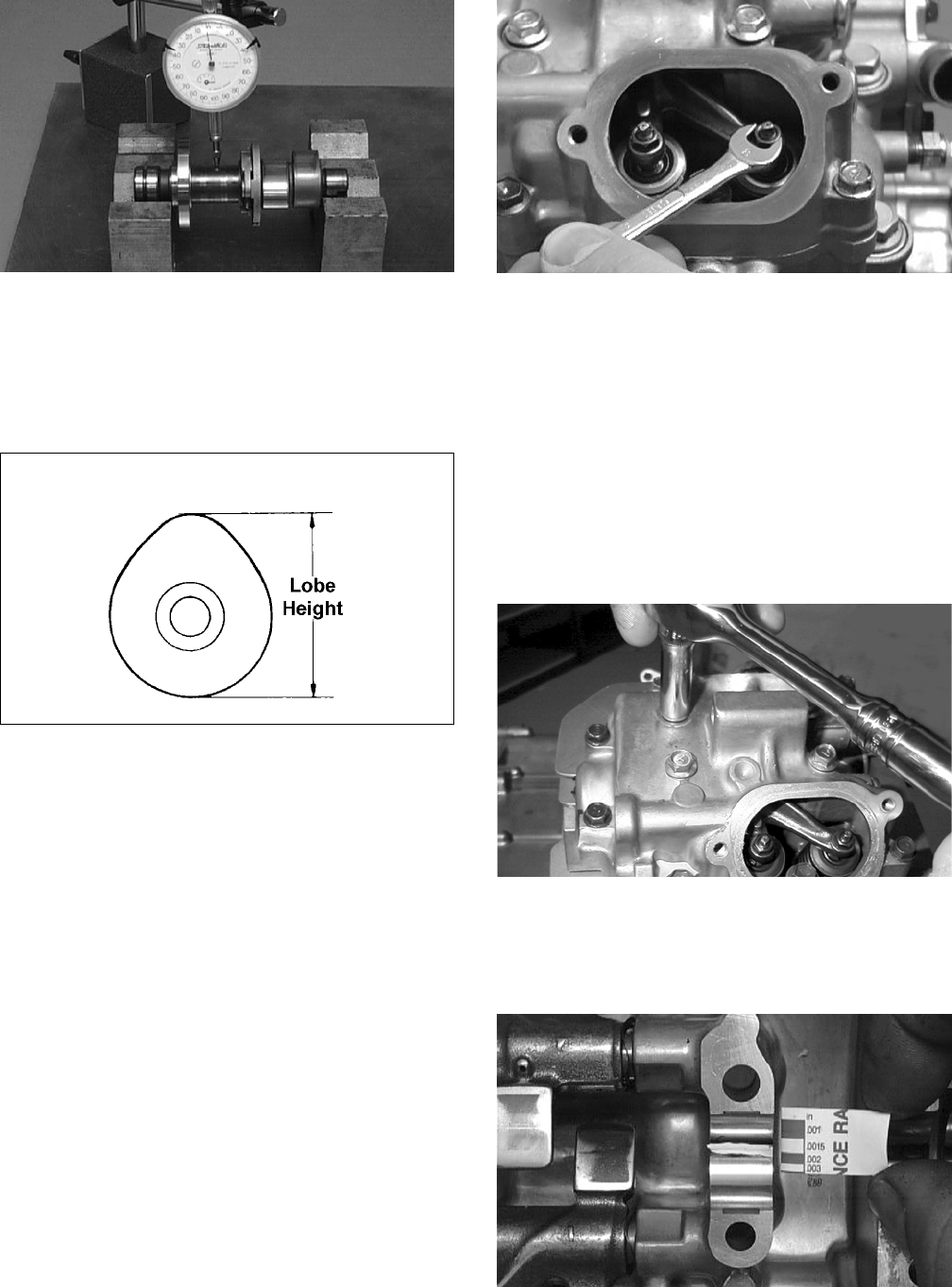
3-100
CC283D
2. Rotate the camshaft and note runout; maximum
tolerance must not exceed specifications.
Measuring Camshaft Lobe Height
1. Using a calipers, measure each cam lobe height.
ATV1013A
2. The lobe heights must not exceed minimum
specifications.
Inspecting Camshaft Bearing
Journal
1. Inspect the bearing journal for scoring, seizure
marks, or pitting.
2. If excessive scoring, seizure marks, or pitting is
found, the cylinder head assembly must be
replaced.
Measuring Camshaft to
Cylinder Head Clearance
1. Remove the adjuster screws and jam nuts.
CC005D
2. Place a strip of plasti-gauge in each of the cam-
shaft lands in the cylinder head.
3. Place the valve cover on the cylinder head and
secure with the valve cover cap screws. Tighten
securely.
NOTE: Do not rotate the camshaft when measur-
ing clearance.
4. Remove the cap screws securing the valve cover
to the cylinder; then remove the valve cover and
camshaft.
MD1261
5. Match the width of the plasti-gauge with the
chart found on the plasti-gauge packaging to
determine camshaft to cylinder head and valve
cover clearance.
CC145D
6. If clearance is excessive, measure the journals of
the camshaft.
FOR ARCTIC CAT ATV DISCOUNT PARTS CALL 606-678-9623 OR 606-561-4983
www.mymowerparts.com
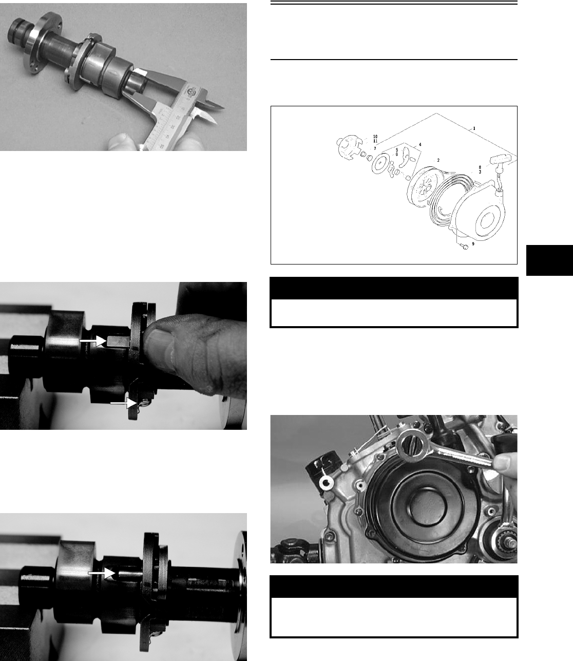
3-101
3
CC287D
NOTE: If the journals are worn, replace the cam-
shaft; then measure the clearance again. If it is still
out of tolerance, replace the cylinder head.
Inspecting Camshaft Spring/Drive
Pin
1. Inspect the spring and unloader pin for damage.
CF061A
NOTE: With the weight extended, the unloader
pin should be flat-side out; with the weight
retracted, the unloader pin should be round-side
out.
CF060A
2. If damaged, the camshaft must be replaced.
Servicing Left-Side
Components
RECOIL STARTER
0737-034
Removing/Disassembling
1. Remove the cap screws securing the recoil
starter assembly to the left-side cover; then
remove the starter.
CC039D
2. Rotate the reel counterclockwise until the notch
of the reel is near the rope guide in the case.
Guide the rope into the notch and slowly allow
the reel to retract until all spiral spring tension is
released.
! WARNING
Always wear safety glasses when servicing the
recoil starter.
! WARNING
During the disassembly procedure, continuous
downward pressure must be exerted on the reel so it
does not accidentally disengage and cause injury.
KEY
1. Recoil Starter Assy
2. Reel
3. Spiral Spring
4. Ratchet Assy
5. Ratchet
6. Ratchet Guide
7. Nut
8. Rope Assy
9. Cap Screw
10. Starter Cup
11. Nut
FOR ARCTIC CAT ATV DISCOUNT PARTS CALL 606-678-9623 OR 606-561-4983
www.mymowerparts.com
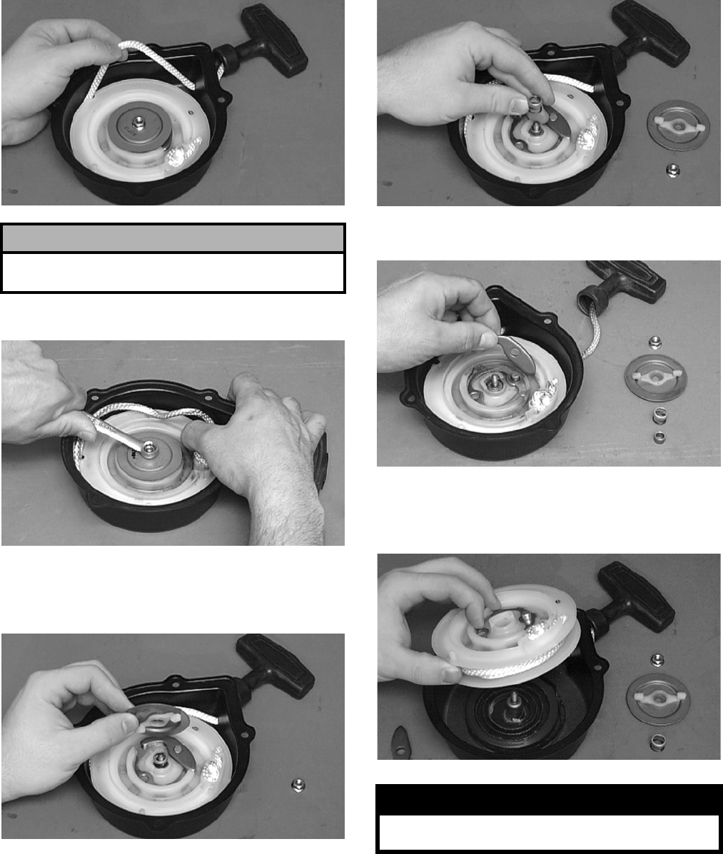
3-102
B600D
3. Remove the nut.
B601D
4. Slowly release the friction plate and lift the plate
with ratchet guide free of the recoil case; then
remove the ratchet guide from the friction plate.
B602D
5. Remove the spring cover, spring, and shaft.
B603D
6. Remove the ratchet and account for the pin.
B604D
7. Carefully lift the reel free of the case making
sure the spiral spring does not accidentally dis-
engage from the case.
B605D
8. Remove the protective cover from the starter
handle and pull the rope out of the handle; then
untie the knot in the rope and remove the han-
dle.
NOTE: Do not remove the spiral spring unless
replacement is necessary. It should be visually
inspected in place to save time. If replacement is
necessary, follow steps 9-10.
! CAUTION
During the disassembly procedure, make sure all
spring tension is released before continuing.
! WARNING
Care must be taken when lifting the reel free of the
case. Wear safety glasses to avoid injury.
FOR ARCTIC CAT ATV DISCOUNT PARTS CALL 606-678-9623 OR 606-561-4983
www.mymowerparts.com
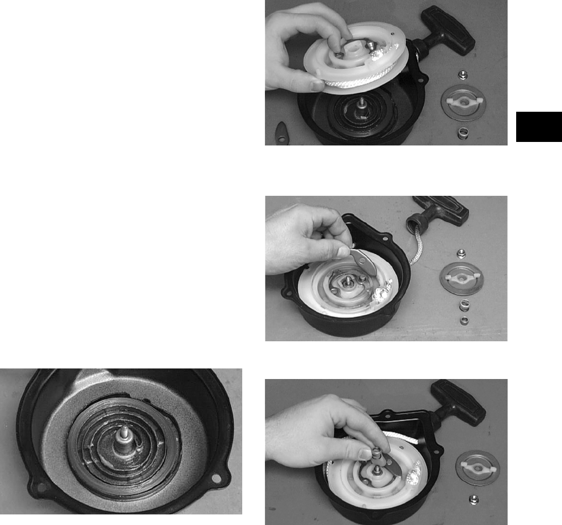
3-103
3
9. Remove the spiral spring from the case by lift-
ing the spring end up and out. Hold the remain-
der of the spring with thumbs and alternately
release each thumb to allow the spring to gradu-
ally release from the case.
10. Unwind the rope from the reel and remove the
rope.
Cleaning and Inspecting
NOTE: Whenever a part is worn excessively,
cracked, or damaged in any way, replacement is
necessary.
1. Clean all components.
2. Inspect the springs and ratchet for wear or dam-
age.
3. Inspect the reel and case for cracks or damage.
4. Inspect the shaft for wear, cracks, or damage.
5. Inspect the rope for breaks or fraying.
6. Inspect the spiral spring for cracks, crystalliza-
tion, or abnormal bends.
7. Inspect the handle for damage, cracks, or deteri-
oration.
Assembling/Installing
1. If removed, insert the spiral spring into the case
with the outer end of the spring around the
mounting lug in the case; then wind it in a coun-
terclockwise direction until the complete spring
is installed.
NOTE: The spiral spring must seat evenly in the
recoil case.
B606D
2. Insert the rope through the hole in the reel and
tie a knot in the end; then wrap the rope counter—
clockwise around the reel leaving approximately
50 cm (20 in.) of rope free of the reel.
3. Apply low-temperature grease to the spring and
hub.
4. Thread the end of the rope through the guide
hole of the case; then thread the rope through the
handle and secure it with a double knot. Install
the protective cover into the handle.
5. Align the inner hook of the spiral spring with the
notch in the reel.
B605D
6. Install the ratchet onto its pin making sure the
end is properly installed on the reel.
B604D
7. Install the shaft, spring, and the spring cover.
B603D
8. Install the friction plate with the ratchet guide
fitting into the ratchet.
FOR ARCTIC CAT ATV DISCOUNT PARTS CALL 606-678-9623 OR 606-561-4983
www.mymowerparts.com
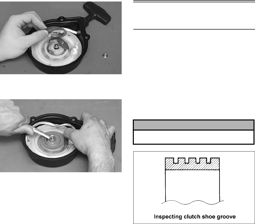
3-104
B602D
9. While pushing down on the reel, install the nut.
Tighten securely.
B601D
10. With the 50 cm (20 in.) of rope exposed, hook
the rope in the notch of the reel.
11. Rotate the reel four turns counterclockwise; then
release the rope from the notch and allow the
rope to retract.
12. Pull the rope out two or three times to check for
correct tension.
NOTE: Increasing the rotations in step 11 will
increase spring tension.
13. Place the recoil starter assembly into position on
the left-side cover; then tighten the cap screws
to specifications.
Servicing Right-Side
Components
NOTE: Whenever a part is worn excessively,
cracked, damaged in any way, or out of tolerance,
replacement is necessary.
INSPECTING CENTRIFUGAL
CLUTCH SHOE
1. Inspect the clutch shoe for uneven wear, chips,
cracks, or discoloration.
2. Inspect the depth of the grooves in the clutch
shoes. If any shoe is worn to the bottom of the
groove, replace the complete set.
ATV1014
INSPECTING CENTRIFUGAL
CLUTCH HOUSING
1. Inspect the clutch housing for burns, marks,
scuffs, cracks, scratches, or uneven wear.
2. If the housing is damaged in any way, the hous-
ing must be replaced.
INSPECTING PRIMARY
ONE-WAY DRIVE
1. Insert the drive into the clutch housing.
2. Rotate the inner race by hand and verify the
inner race rotates only one direction.
3. If the inner race is locked in place or rotates both
directions, the drive assembly must be replaced.
! CAUTION
Always replace clutch shoes as a complete set or
severe imbalance could occur.
FOR ARCTIC CAT ATV DISCOUNT PARTS CALL 606-678-9623 OR 606-561-4983
www.mymowerparts.com
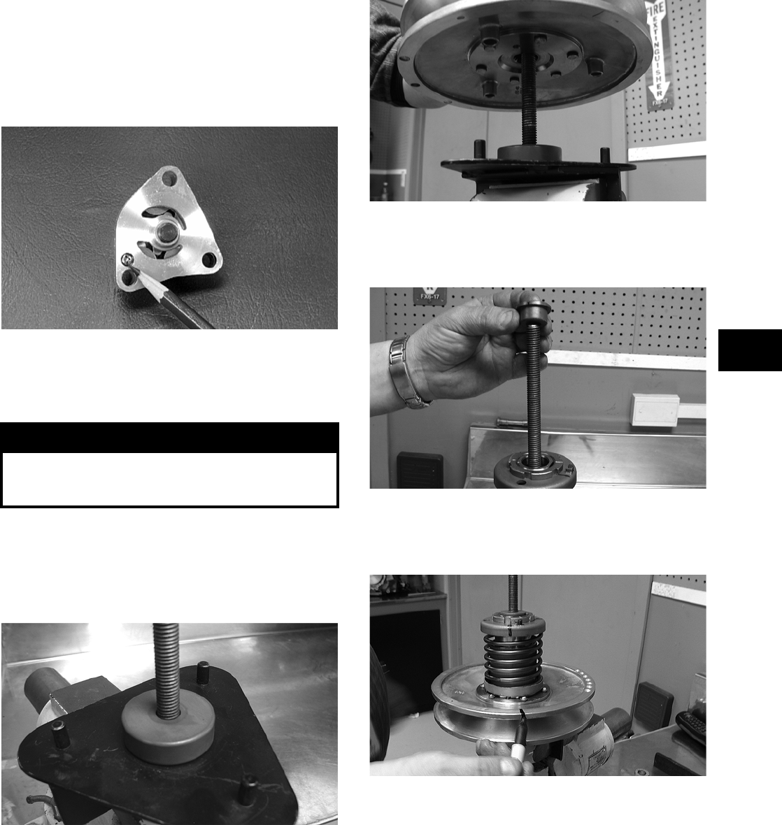
3-105
3
INSPECTING OIL PUMP
1. Inspect the pump for damage.
2. It is inadvisable to remove the screw securing
the pump halves. If the oil pump is damaged, it
must be replaced.
CC446D
DRIVEN PULLEY ASSEMBLY
Disassembling
1. Secure Driven Pulley Compressor (p/n
0444-140) in a suitable holding fixture such as a
bench vise; then remove the wing nut, holding
handle, flat washer, and pilot bushing leaving
the large spacer on the compressor tool base.
CD047
2. Place the driven pulley assembly onto the com-
pressor tool base engaging the dowel pins into
appropriate holes in the fixed face of the assem-
bly.
CD048
3. Install the pilot bushing with the machined end
directed down; then fit the bushing into the pul-
ley hub.
CD067
4. Using a suitable marking pen, make alignment
marks on the fixed face spring holder and both
pulley faces.
CD049
5. Place the holding handle on the spring holder
fitting the two dowel pins into the spring holder
face; then install a flat washer and the wing nut.
Turn the wing nut down until resistance is felt.
NOTE: Do not use the wing nut to compress the
spring further.
! WARNING
This procedure involves relaxing a compressed
spring assembly. DO NOT attempt disassembling
without the proper tools.
FOR ARCTIC CAT ATV DISCOUNT PARTS CALL 606-678-9623 OR 606-561-4983
www.mymowerparts.com
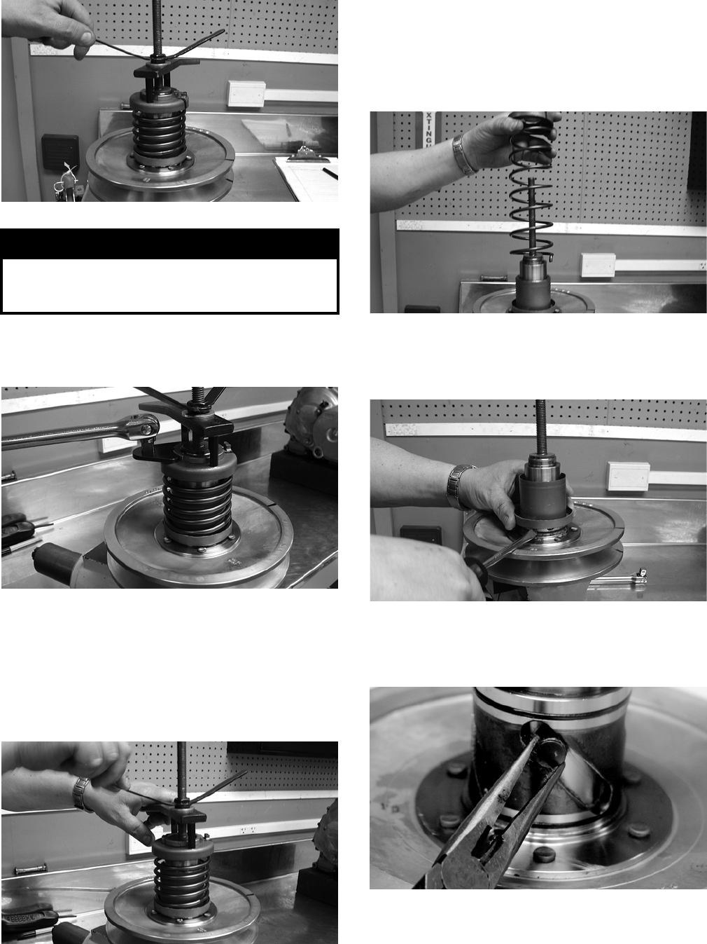
3-106
CD050
6. Using a spanner and suitable breaker bar, loosen
the notched-ring nut; then spin the nut free of
the hub.
CD051
7. Firmly hold the handle and slowly turn the wing
nut counterclockwise to relax the spring.
NOTE: There will be a tendency for the handle to
rotate clockwise approximately ¼ turn as the
spring holder clears the flats or hub. This is due to
a slight counterclockwise preload on the spring.
CD052
8. Release the preload slowly; then continue to
relax the spring until the wing nut is flush with
the end of the threads.
9. Firmly holding the spring and spring holder,
remove the wing nut; then remove the spring.
CD053
10. Using a thin pry-bar or screwdriver, work the
movable face sleeve upward and free of the
O-rings; then remove the sleeve.
CD054
11. Remove the three pins and spacers from the cam
slots in the movable face; then remove the mov-
able face.
CF091
! WARNING
The spring assembly is under pressure. Extreme
care must be taken when relaxing the spring. Always
wear safety glasses. Use proper tools only.
FOR ARCTIC CAT ATV DISCOUNT PARTS CALL 606-678-9623 OR 606-561-4983
www.mymowerparts.com
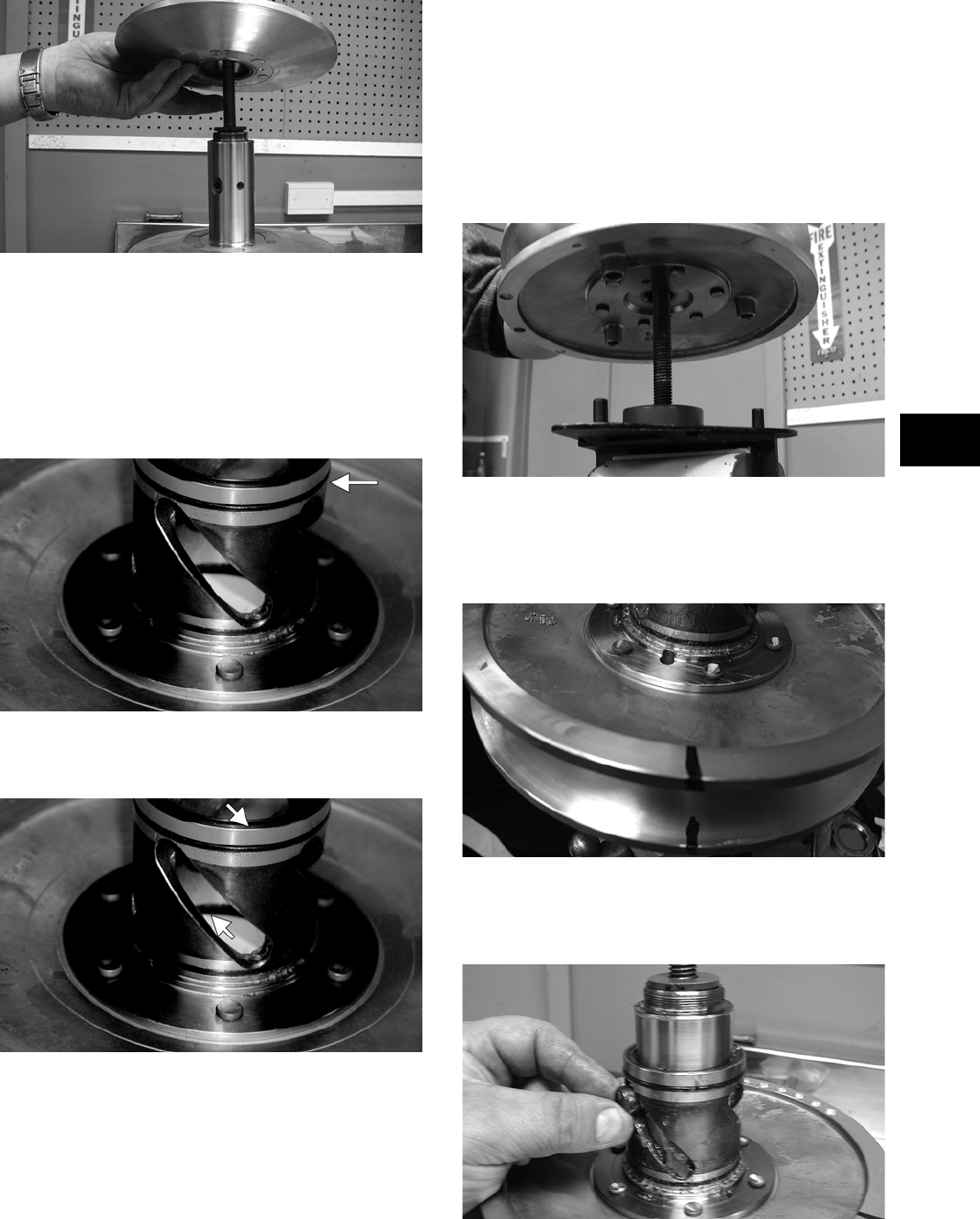
3-107
3
CD056
Inspecting
1. Inspect the pulley faces for wear, galling, or
grooving.
2. Inspect the O-rings on the movable face for
nicks, tears, or swelling.
CF092A
3. Inspect two grease seals in the movable face for
nicks, cuts, or damage.
CF095A
4. Inspect the pins and bushings for wear, flat
spots, looseness, or cracking.
Assembling
1. Place the fixed face of the driven pulley on the
pulley compressor base making sure the dowel
pins are engaged in the appropriate holes in the
pulley face.
NOTE: Make sure the spacer is on the base or
damage to the fixed face will occur when the
spring is compressed.
CD048
2. Apply multi-purpose grease to the O-rings and
grease seals on the movable face; then install on
the fixed face making sure the alignment marks
are properly aligned.
CD060
3. Install the three pins and spacers into the fixed
face hub; then pack the cam slots in the movable
face with multi-purpose grease.
CD061
FOR ARCTIC CAT ATV DISCOUNT PARTS CALL 606-678-9623 OR 606-561-4983
www.mymowerparts.com
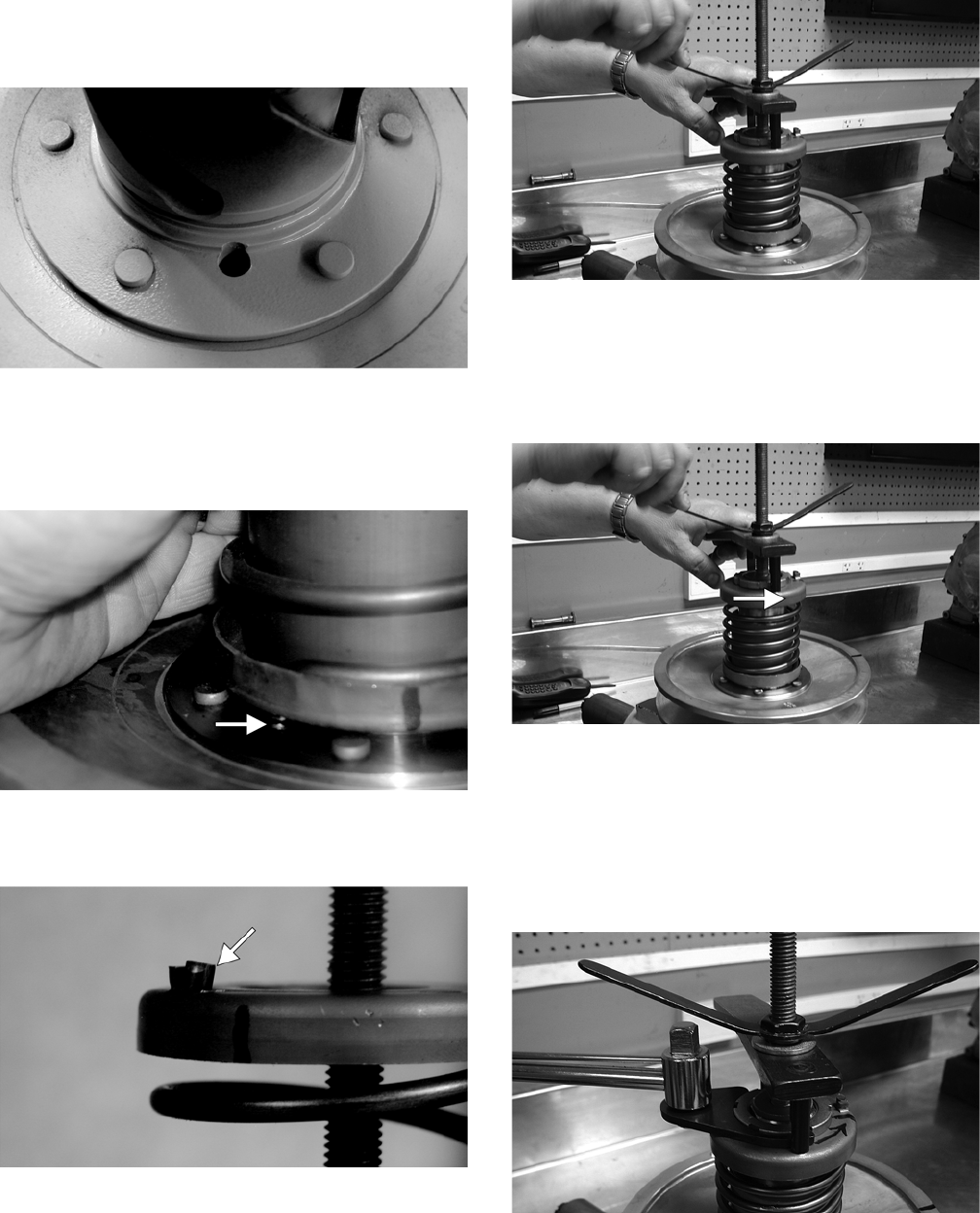
3-108
4. Install the movable face sleeve aligning the hole
in the spring seat with the spring anchor hole in
the movable face.
CF097
5. Install the spring over the hub and movable face
sleeve; then insert the end of the spring through
the sleeve and into the spring anchor hole in the
movable face.
CF089A
6. Place the spring holder on the spring engaging
the spring end with the appropriate anchor hole.
CF087A
7. Assemble the notched-ring nut, spring holding
handle, one flat washer, and the wing nut in
order on the pulley compressor bolt; then thread
the wing nut onto the bolt.
CD052
8. Compress the spring until the spring holder
nears the threads on the fixed face hub; then
using the handle, wind the spring holder coun-
terclockwise to align the flats of the spring
holder and hub.
CD052A
9. Continue compressing the spring while guiding
the spring holder onto the hub. When a slight
resistance is felt, stop turning the wing nut.
10. Install the nut (threads coated with red Loctite
#271); then tighten the nut to specification using
the spanner and a torque wrench.
CD066
11. Remove the wing nut, washer, and holding han-
dle; then remove the driven pulley from the pul-
ley compressor.
FOR ARCTIC CAT ATV DISCOUNT PARTS CALL 606-678-9623 OR 606-561-4983
www.mymowerparts.com
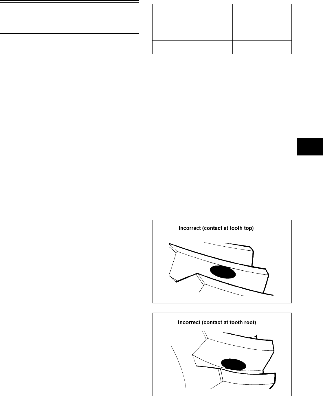
3-109
3
Servicing Center
Crankcase Components
NOTE: Whenever a part is worn excessively,
cracked, damaged in any way, or out of tolerance,
replacement is necessary.
SECONDARY GEARS
NOTE: When checking and correcting secondary
gear backlash and tooth contact, the universal
joint must be secured to the front shaft or false
measurements will occur.
Checking Backlash
NOTE: The rear shaft and bevel gear must be
removed for this procedure. Also, always start with
the original shims on the rear shaft.
1. Place the left-side crankcase cover onto the
left-side crankcase half to prevent runout of the
secondary transmission output shaft.
2. Install the secondary driven output shaft assem-
bly onto the crankcase.
3. Mount the indicator tip of the dial indicator on
the secondary driven bevel gear.
4. While rocking the driven bevel gear back and
forth, note the maximum backlash reading on
the gauge.
5. Acceptable backlash range is 0.05-0.33 mm
(0.002-0.013 in.).
Correcting Backlash
NOTE: If backlash measurement is within the
acceptable range, no correction is necessary.
1. If backlash measurement is less than specified,
remove an existing shim, measure it, and install
a new thinner shim.
2. If backlash measurement is more than specified,
remove an existing shim, measure it, and install
a thicker shim.
NOTE: Continue to remove, measure, and install
until backlash measurement is within tolerance.
Note the following chart.
Checking Tooth Contact
NOTE: After correcting backlash of the second-
ary driven bevel gear, it is necessary to check
tooth contact.
1. Remove the secondary driven output shaft
assembly from the left-side crankcase half.
2. Clean the secondary driven bevel gear teeth of
old oil and grease residue.
3. Apply a thin, even coat of a machinist-layout
dye to several teeth of the gear.
4. Install the secondary driven output shaft assem-
bly.
5. Rotate the secondary driven bevel gear several
revolutions in both directions.
6. Examine the tooth contact pattern in the dye and
compare the pattern to the illustrations.
ATV-0103
ATV-0105
Backlash Measurement Shim Correction
Under 0.05 mm (0.002 in.) Decrease Shim
Thickness
At 0.05-0.33 mm
(0.002-0.013 in.)
No Correction Required
Over 0.33 mm (0.013 in.) Increase Shim
Thickness
FOR ARCTIC CAT ATV DISCOUNT PARTS CALL 606-678-9623 OR 606-561-4983
www.mymowerparts.com
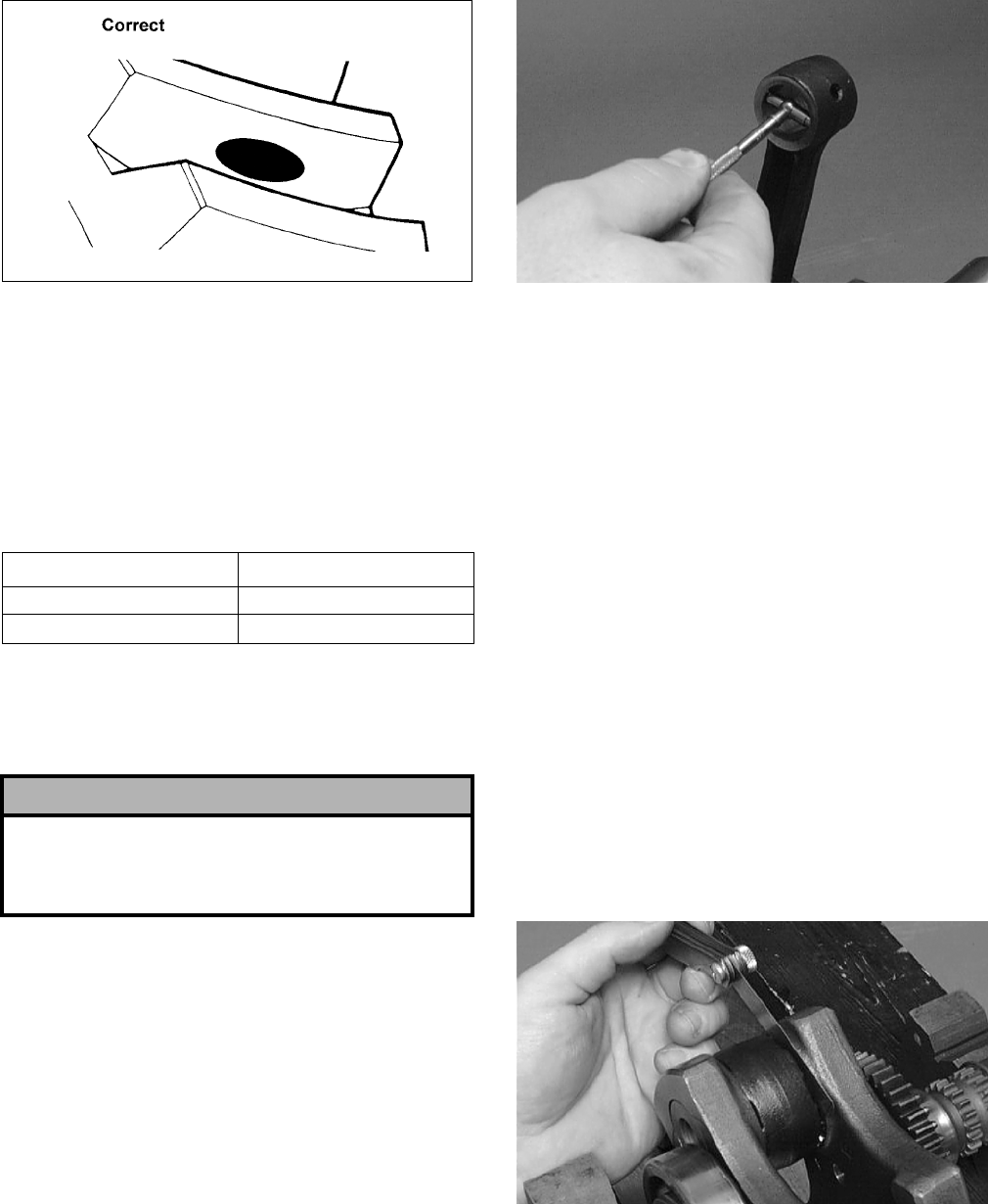
3-110
ATV-0104
Correcting Tooth Contact
NOTE: If tooth contact pattern is comparable to
the correct pattern illustration, no correction is
necessary.
If tooth contact pattern is comparable to an incorrect
pattern, correct tooth contact according to the fol-
lowing chart.
NOTE: To correct tooth contact, steps 1 and 2
(with NOTE) of “Correcting Backlash” must be fol-
lowed and the above “Tooth Contact/Shim Correc-
tion” chart must be consulted.
CRANKSHAFT ASSEMBLY
Measuring Connecting Rod
(Small End Inside Diameter)
1. Insert a snap gauge into the upper connecting
rod small end bore; then remove the gauge and
measure it with micrometer.
CC290D
2. Maximum diameter must not exceed specifica-
tions.
Measuring Connecting Rod
(Small End Deflection)
1. Place the crankshaft on a set of V-blocks and
mount a dial indicator and base on the surface
plate. Position the indicator contact point against
the center of the connecting rod small end jour—
nal.
2. Zero the indicator and push the small end of the
connecting rod away from the dial indicator.
3. Maximum deflection must not exceed specifica-
tions.
Measuring Connecting Rod
(Big End Side-to-Side)
1. Push the lower end of the connecting rod to one
side of the crankshaft journal.
2. Using a feeler gauge, measure the gap between
the connecting rod and crankshaft journal.
CC289D
3. Acceptable gap range must be within specifica-
tions.
Tooth Contact Shim Correction
Contacts at Top Decrease Shim Thickness
Contacts at Root Increase Shim Thickness
! CAUTION
After correcting tooth contact, backlash must again
be checked and corrected (if necessary). Continue
the correcting backlash/correcting tooth contact pro-
cedures until they are both within tolerance values.
FOR ARCTIC CAT ATV DISCOUNT PARTS CALL 606-678-9623 OR 606-561-4983
www.mymowerparts.com
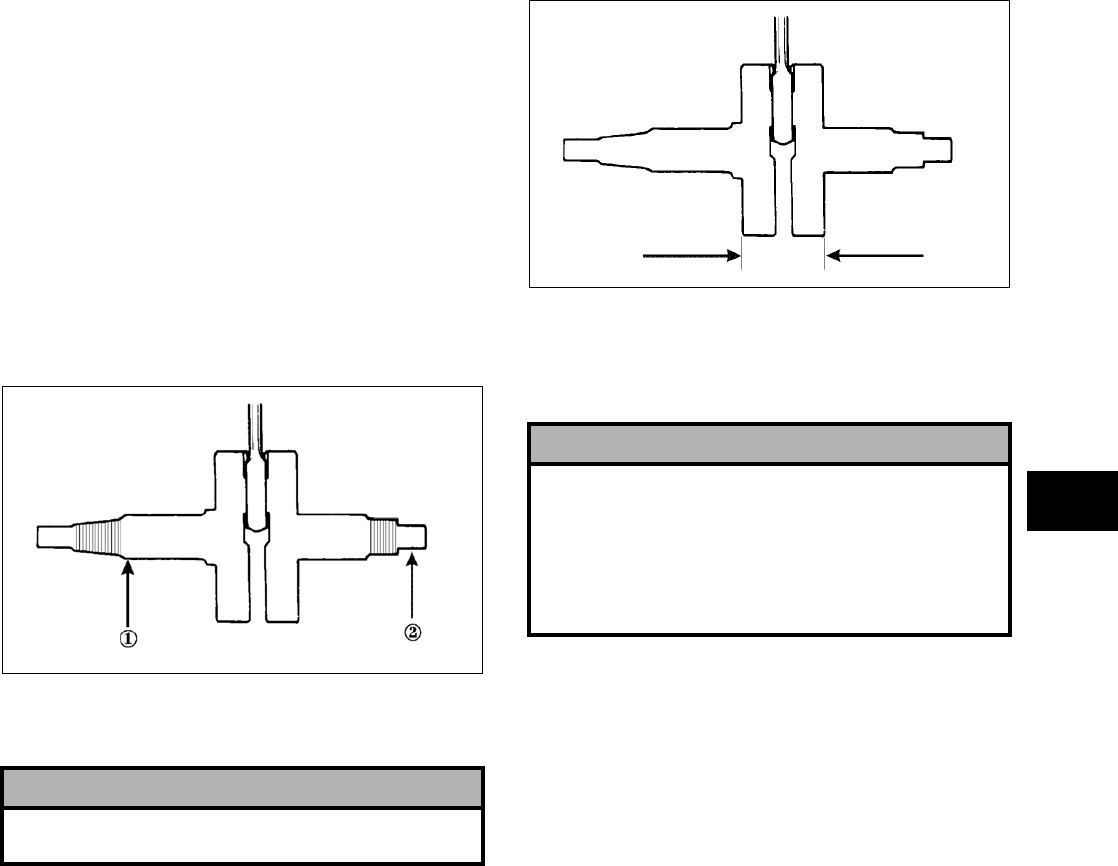
3-111
3
Measuring Connecting Rod
(Big End Width)
1. Using a calipers, measure the width of the
connecting rod at the big-end bearing.
2. Acceptable width range must be within specifi-
cations.
Measuring Crankshaft (Runout)
1. Place the crankshaft on a set of V blocks.
2. Mount a dial indicator and base on the surface
plate. Position the indicator contact at point 1 of
the crankshaft.
ATV-1074
3. Zero the indicator and rotate the crankshaft
slowly.
4. Maximum runout must not exceed specifica-
tions.
NOTE: Proceed to check runout on the other end
of the crankshaft by positioning the indicator con—
tact at point 2 and following steps 2-4.
Measuring Crankshaft
(Web-to-Web)
1. Using a calipers, measure the distance from the
outside edge of one web to the outside edge of
the other web.
ATV-1017
2. Acceptable width range must be within specifi-
cations.
COUNTERSHAFT
Disassembling
1. Remove the reverse driven gear dog; then
remove the circlip securing the reverse driven
gear.
2. Remove the reverse driven gear and account for
the washer, bushing, and bearing.
3. Remove the low driven gear washer; then
remove the low driven gear. Account for the
bushing and bearing.
4. Remove the washer; then remove the circlip
securing the sliding dog. Remove the sliding
dog.
5. Remove the high driven gear circlip; then
remove the high driven gear. Account for the
washer, bushing, and bearing.
! CAUTION
Care should be taken to support the connecting rod
when rotating the crankshaft.
! CAUTION
When disassembling the countershaft, care must be
taken to note the direction each major component
(dog, gear) faces. If a major component is installed
facing the wrong direction, transmission damage
may occur and/or the transmission will malfunction.
In either case, complete disassembly and assembly
will be required.
FOR ARCTIC CAT ATV DISCOUNT PARTS CALL 606-678-9623 OR 606-561-4983
www.mymowerparts.com
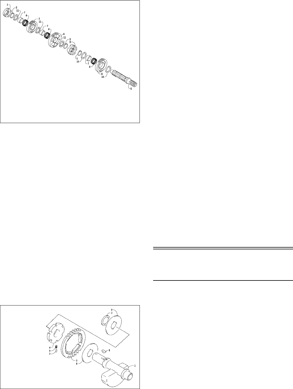
3-112
Assembling
737-053A
1. Place the high driven gear onto the countershaft
making sure the bearing, bushing, and washer
are properly positioned. Secure with the circlip.
2. Place the sliding dog onto the countershaft; then
secure with the circlip. Place the washer next to
the circlip.
3. Place the low driven gear onto the countershaft
making sure the bearing and bushing are prop-
erly positioned; then place the washer onto the
shaft.
4. Place the reverse driven gear onto the counter-
shaft making sure the bearing, bushing, and
washer are properly positioned; then secure with
the circlip.
5. Place the reverse driven gear dog onto the coun-
tershaft; then secure with the circlip.
NOTE: The countershaft is now completely
assembled for installation.
CRANK BALANCER DRIVEN GEAR
737-050A
Disassembling
1. Remove the small and large washers from the
balancer shaft.
2. Note the position of the alignment marks for
assembling purposes; then remove driven gear
#1 with driven gear #2. Account for pins and
springs.
3. Remove driven gear #2 from gear #1; then
account for a large washer and a key.
Inspecting
1. Inspect the gear, pins, and keyway for wear.
2. Inspect the springs for damage or fatigue.
Assembling
1. Place driven gear #2 into driven gear #1; then
align the alignment marks of driven gear #1 and
driven gear #2.
2. Using a pair of needle-nose pliers, insert each
spring part way into the slot; then install a pin
and push the spring/pin assembly into the slot.
3. Place the key and the large washer into position
on the balancer shaft.
4. Place the driven gear #1 assembly onto the bal-
ancer shaft; then place the large and small wash-
ers onto the shaft.
NOTE: The crank balancer/driven gear assembly
is now completely assembled for installation.
Assembling Crankcase
Half
NOTE: For ease of assembly, install components
on the right-side crankcase half.
NOTE: If the output shaft was removed, make
sure that the proper shim is installed.
1. Install the output shaft into the crankcase mak-
ing sure the two gears, shim, washer, and nut are
in the correct order.
KEY
1. Reverse Driven Gear Dog
2. Reverse Driven Gear
3. Circlip
4. Bearing
5. Countershaft
6. Low Driven Gear
7. Bushing
8. High Driven Gear
9. Sliding Dog
10. Lock Washer
11. Lock Washer
KEY
1. Balancer Shaft
2. Washer
3. Driven Gear #1
4. Driven Gear #2
5. Spring
6. Key
7. Pin
8. Washer
FOR ARCTIC CAT ATV DISCOUNT PARTS CALL 606-678-9623 OR 606-561-4983
www.mymowerparts.com
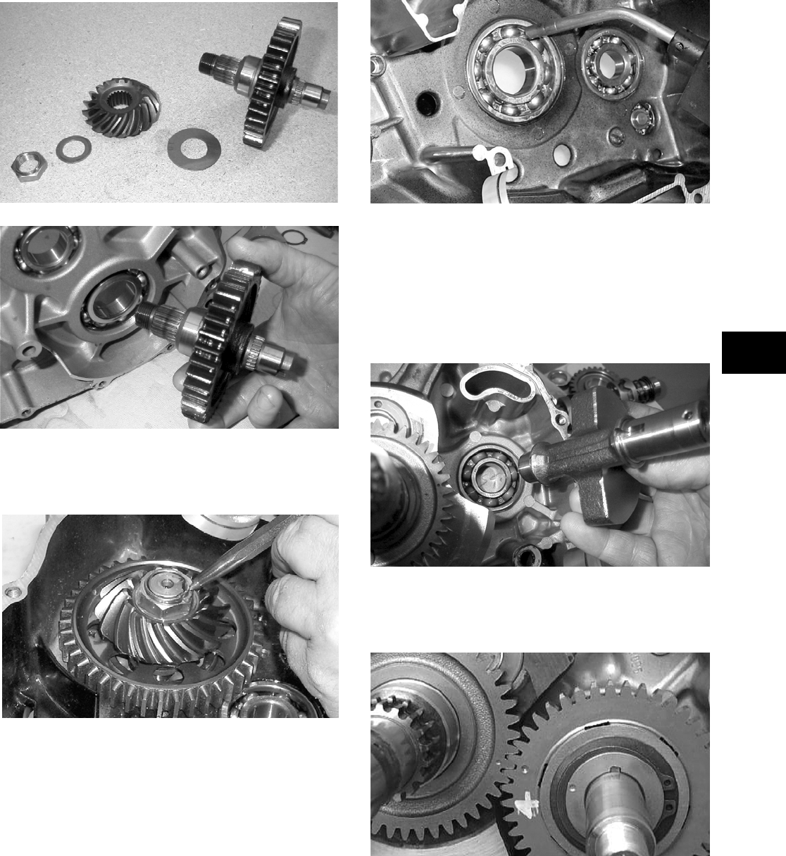
3-113
3
MD1199
MD1079
2. Apply red Loctite #271 to the threads of the out-
put shaft. Install and tighten the nut specifica-
tions. Using a punch, peen the nut.
MD1333
3. Apply a liberal amount of oil to the crankshaft
bearing. Using a propane torch, heat the bearing
until the oil begins to smoke; then slide the
crankshaft assembly into place.
MD1334
NOTE: If heating the bearing is not possible, the
crankshaft can be installed using a crankshaft
installer.
4. Rotate the crankshaft so the counterweight is
toward the rear of the engine. Install the counter-
balance shaft.
MD1024
5. Keeping the counterbalance gear timing mark
aligned with the one on the crankshaft gear,
install the key and the counterbalance gear.
CC166D
6. Keeping the two holes facing up, install the shift
cam and inner and outer washers.
FOR ARCTIC CAT ATV DISCOUNT PARTS CALL 606-678-9623 OR 606-561-4983
www.mymowerparts.com
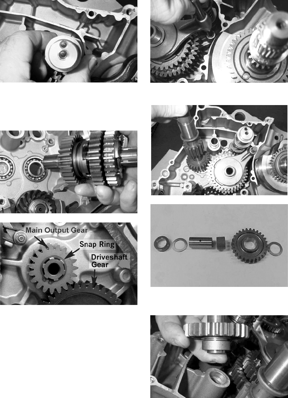
3-114
MD1329
7. Align the inner shift fork with the gear cluster
and with the inner washer in place, install the
gear cluster and inner shift fork. While holding
the gear cluster in place, install the washer, gear,
and snap ring.
MD1032
MD1198
8. Install the outer shift fork and the shift fork
shaft.
MD1327
9. Install the input driveshaft.
MD1326
CC870
10. Install the washer, spacer, sleeve, reverse idler
gear, and washer.
MD1357
FOR ARCTIC CAT ATV DISCOUNT PARTS CALL 606-678-9623 OR 606-561-4983
www.mymowerparts.com
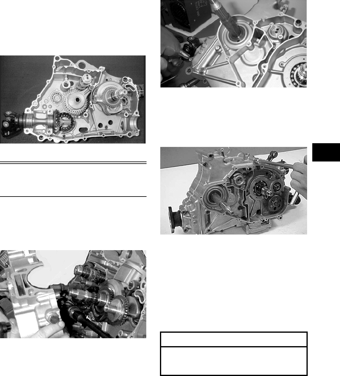
3-115
3
11. Install the secondary and primary driveshaft
assemblies. Account for the bearing alignment
C-ring on the bearing boss next to the pinion
gear.
NOTE: Align the bearing alignment pin on the
secondary output shaft.
MD1316
Joining Crankcase
Halves
1. Verify that the two alignment pins are in place
and that both case halves are clean and grease
free. Apply Three Bond Sealant to the mating
surfaces. Place the right-side half onto the
left-side half.
MD1336
2. Using a plastic mallet, lightly tap the case halves
together until cap screws can be installed.
3. From the right side, install the crankcase cap
screws noting the location of the different-sized
cap screws; then tighten only until snug.
NOTE: Rotate the shafts back and forth to
ensure no binding or sticking occurs while tighten-
ing the cap screws.
MD1008
4. From the left side, install the remaining crank-
case cap screws; then tighten only until snug.
NOTE: Rotate the shafts back and forth to
ensure no binding or sticking occurs while tighten-
ing the cap screws.
CC871
5. In a crisscross/case-to-case pattern, tighten the 8
mm cap screws until the halves are correctly
joined; then tighten to specifications.
NOTE: Rotate the shafts back and forth to
ensure no binding or sticking occurs.
6. In a crisscross/case-to-case pattern, tighten the 6
mm cap screws to specifications.
NOTE: Rotate the shafts back and forth to
ensure no binding or sticking occurs.
AT THIS POINT
After completing center crankcase components,
proceed to Installing Right-Side Components, to
Installing Left-Side Components, and to Installing
Top-Side Components.
FOR ARCTIC CAT ATV DISCOUNT PARTS CALL 606-678-9623 OR 606-561-4983
www.mymowerparts.com
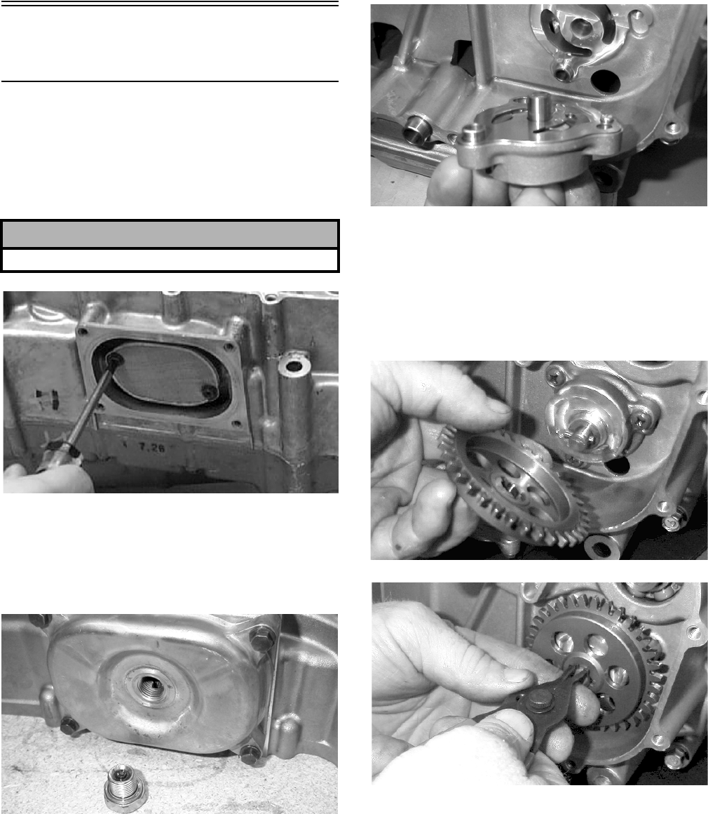
3-116
Installing Right-Side
Components
A. Oil Strainer/Oil Pump
1. Place the oil strainer and new O-ring into posi-
tion beneath the crankcase. Tighten the Phil-
lips-head screws (coated with red Loctite #271)
securely.
MD1337
2. Noting the directional arrow from removing,
place the strainer cover into position on the
crankcase making sure the O-ring is properly
installed and secure with the four cap screws;
then tighten the oil drain plug to specifications.
MD1208
3. Place two alignment pins and the oil pump into
position on the crankcase and secure with the
Phillips-head screws coated with blue Loctite
#243. Tighten to specifications.
MD1060
4. Place the pin into position on the oil pump shaft,
install the oil pump driven gear making sure the
recessed side of the gear is directed inward, and
secure with a new snap ring.
NOTE: Always use a new snap ring when install-
ing the oil pump driven gear.
MD1020
MD1019
5. Install the cam chain.
NOTE: Keep tension on the cam chain to avoid
damaging the crankcase boss.
6. Place the pin into position, install the oil pump
drive gear, and tighten the cap screw (coated
with red Loctite #271) securely.
! CAUTION
The legs of the strainer must be directed out.
FOR ARCTIC CAT ATV DISCOUNT PARTS CALL 606-678-9623 OR 606-561-4983
www.mymowerparts.com
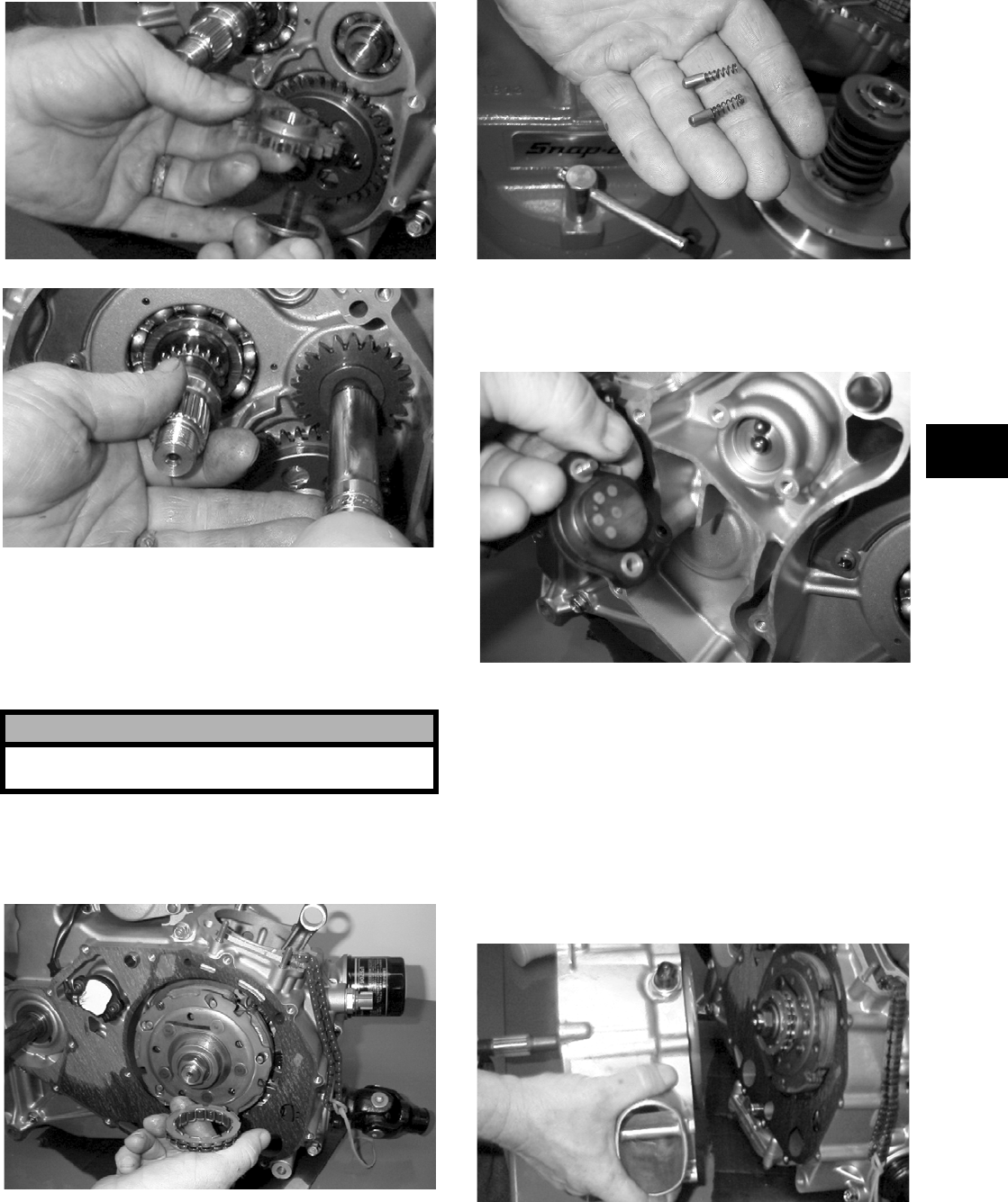
3-117
3
MD1017
MD1018
7. Install the clutch shoe assembly on the crank-
shaft; then install the flange nut (left-hand
thread). Tighten to specifications.
NOTE: The flat side of the flange nut should be
directed towards the clutch shoe.
8. Install the one-way sprag clutch making sure
that the green dot or the stamp tag OUTSIDE is
directed away from the crankcase.
MD1286
9. Install gear position indicator switch contact
pins and springs into the end of the shift shaft.
MD1043
10. Install gear position indicator switch making
sure the O-ring is well-oiled and properly posi-
tioned. Tighten cap screws securely.
MD1040
B. Clutch Cover
C. Fixed Drive Face
D. Movable Drive Face
NOTE: Steps 1-10 in the preceding sub-section
must precede this procedure.
11. Install two alignment pins and place the clutch
cover gasket into position. Install the clutch
cover.
MD1115
12. Tighten the clutch cover cap screws to specifica-
tions.
! CAUTION
Care must be taken when installing the flange nut;
it has “left-hand” threads.
FOR ARCTIC CAT ATV DISCOUNT PARTS CALL 606-678-9623 OR 606-561-4983
www.mymowerparts.com
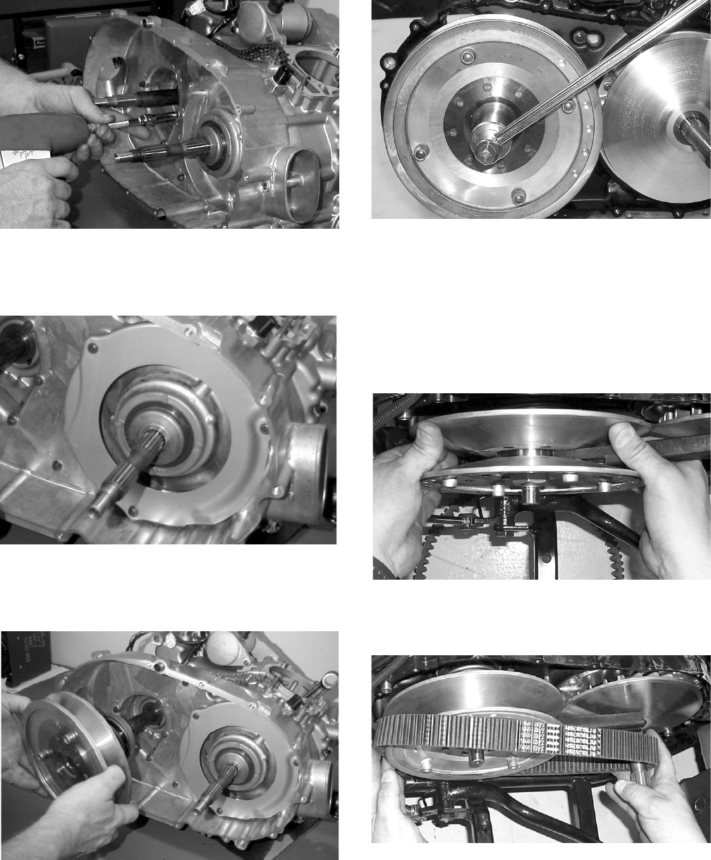
3-118
MD1117
13. Install the air intake plate. Apply red Loctite
#271 to the threads of the three Phillips-head
cap screws; then install and tighten securely.
MD1342
14. Place the driven pulley assembly into position
and secure with the nut (threads coated with red
Loctite #271). Tighten to specifications.
MD1068
MD1339
15. Slide the fixed drive face assembly onto the
front shaft.
16. Spread the faces of the driven pulley by pushing
the inner face toward the engine while turning it
counterclockwise; then when the faces are sepa-
rated, insert a wedge (approximately 3/8 in.
thick) between the faces. Release the inner face.
MD1340
17. Place the V-belt into position on the driven pul-
ley and over the front shaft.
MD1341
NOTE: The arrows on the V-belt should point for-
ward.
FOR ARCTIC CAT ATV DISCOUNT PARTS CALL 606-678-9623 OR 606-561-4983
www.mymowerparts.com
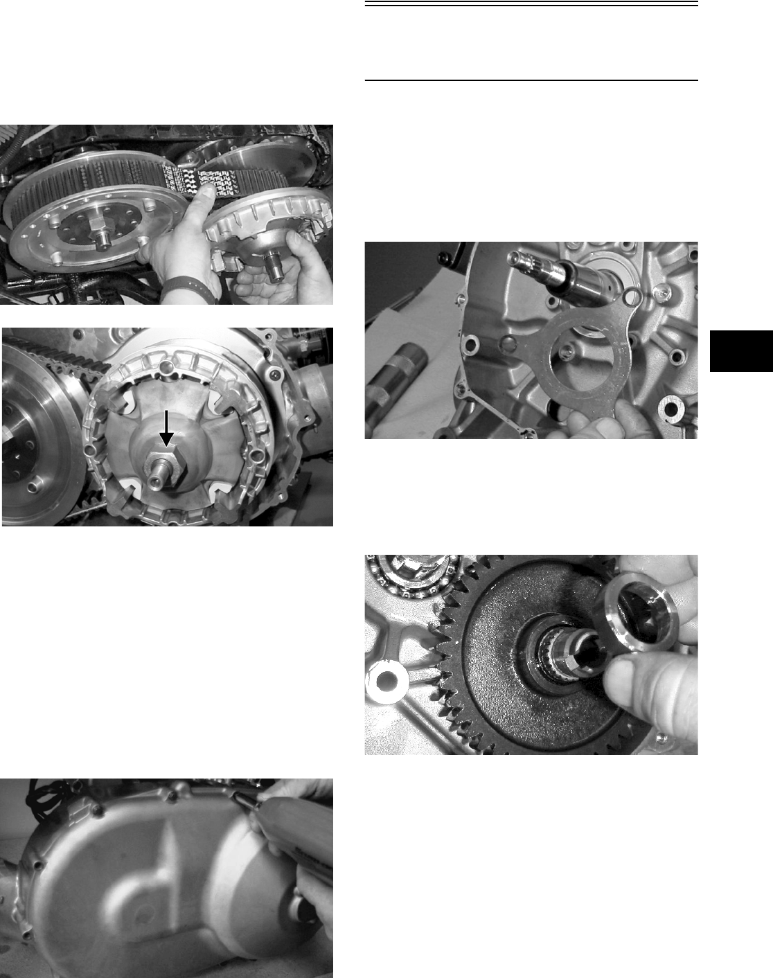
3-119
3
18. Making sure the eight movable drive face rollers
are in position, pinch the V-belt together near its
center and slide the spacer and movable drive
face onto the shaft. Coat the threads of the nut
with red Loctite #271 and secure the movable
drive face. Tighten the nut to specifications.
MD1338
MD1033
NOTE: At this point, the wedge can be removed
from between the driven pulley faces.
19. Rotate the V-belt and drive/driven assemblies
until the V—belt is flush with the top of the driven
pulley.
20. Install two alignment pins and place the V-belt
cover gasket into position on the clutch cover.
Install the V-belt cover noting the position of the
long cap screws and rubber washer and two wire
forms. In a crisscross pattern, tighten cap screws
to specifications.
MD1306
Installing Left-Side
Components
A. Starter Idler Gears
B. Rotor/Flywheel
1. Place the crankshaft bearing retainer into posi-
tion. Apply red Loctite #271 to the three Phil-
lips-head screws. Install and tighten the three
Phillips-head screws securely.
MD1122
2. Install the starter motor and tighten the two cap
screws securely.
3. Install the driveshaft spacer making sure the
stepped side is to the inside.
MD1224
4. Install the shift detent cam making sure the
spacer is properly positioned.
FOR ARCTIC CAT ATV DISCOUNT PARTS CALL 606-678-9623 OR 606-561-4983
www.mymowerparts.com
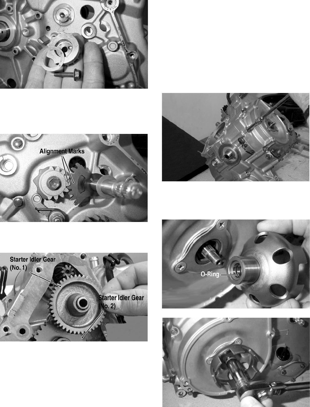
3-120
MD1086
5. Install the cam stopper assembly.
6. Install the gear shift shaft assembly and washer
making sure to align the alignment marks.
MD1239
7. Install starter idler gear (No. 1) and starter idler
gear (No. 2).
MD1305
8. Place the key into its notch; then slide the rotor/
flywheel (with the ring gear in place) over the
crankshaft. Tighten the nut to specifications.
C. Cover
D. Recoil Starter
NOTE: Steps 1-8 in the preceding sub-section
must precede this procedure.
9. Install two alignment pins and place the left-side
cover gasket into position. Install the left-side
cover. Noting the different-lengthed 6 mm cap
screws, the position of the shifter bracket, and
the location of the long cap screw with the
washer, tighten cap screws only until snug.
MD1186
10. Install the starter cup making sure that the
O-ring is in place inside the starter cup. Tighten
the nut w/lock washer to specifications.
MD1304
MD1303
11. Tighten the cap screws (from step 9) in a criss-
cross pattern to specifications.
FOR ARCTIC CAT ATV DISCOUNT PARTS CALL 606-678-9623 OR 606-561-4983
www.mymowerparts.com
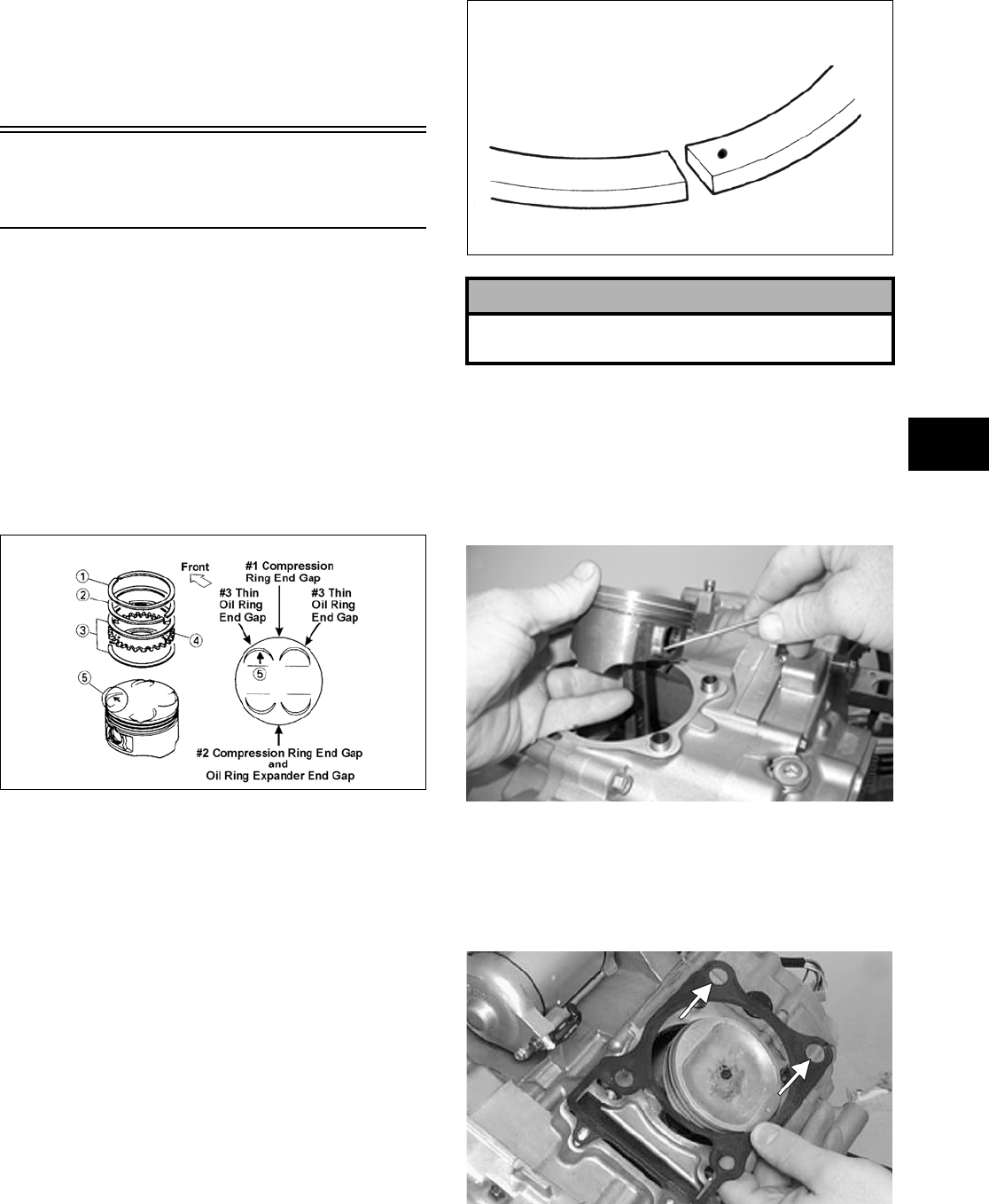
3-121
3
12. Place the gasket, recoil starter assembly, and
cover into position on the left-side cover making
sure the single washer is properly positioned;
then install and tighten the four cap screws to
specifications.
Installing Top-Side
Components
A. Piston
B. Cylinder
NOTE: If the piston rings were removed, install
them in this sequence.
A. Install ring expander (4) in the bottom groove
of the piston; then install the thin oil rings (3)
over the expander making sure the expander
ends do not overlap. Stagger the end gaps of
the upper and lower thin oil rings according
to the illustration.
ATV-1085B
NOTE: Note the direction of the exhaust side of
the piston (5) for correct ring end gap orientation.
B. Install the compression rings (1 and 2) so the
letter on the top surface of each ring faces the
dome of the piston. Rotate the rings until the
ring end gaps are on directly opposite sides of
the piston according to the illustration.
NOTE: The chrome (silver) ring should be
installed in the top position.
MD1343
1. Install the piston on the connecting rod making
sure there is a circlip on each side and the open
end of the circlip is directed upwards or down-
wards.
NOTE: The piston should be installed so the
arrow points towards the exhaust.
MD1213
2. Place the two alignment pins into position. Place
the cylinder gasket into position; then place a
piston holder (or suitable substitute) beneath the
piston skirt and square the piston in respect to
the crankcase.
MD1344
! CAUTION
Incorrect installation of the piston rings will result in
engine damage.
FOR ARCTIC CAT ATV DISCOUNT PARTS CALL 606-678-9623 OR 606-561-4983
www.mymowerparts.com
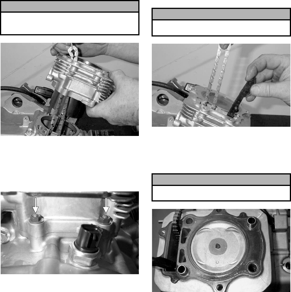
3-122
3. Lubricate the inside wall of the cylinder; then
using a ring compressor or the fingers, compress
the rings and slide the cylinder over the piston.
Route the cam chain up through the cylinder
cam chain housing; then remove the piston
holder and seat the cylinder firmly on the crank-
case.
MD1345
4. Loosely install the two nuts with washers which
secure the cylinder to the right-side crankcase
half.
NOTE: The two cylinder-to-crankcase nuts will
be tightened in step 9.
MD1226A
C. Cylinder Head
D. Valve Cover
NOTE: Steps 1-4 in the preceding sub-section
must precede this procedure.
5. While keeping tension on the cam chain, place
the front cam chain guide into the cylinder.
MD1349
6. Place the head gasket into position on the cylin-
der. Place the alignment pins into position; then
place the head assembly into position on the cyl-
inder making sure the cam chain is routed
through the chain cavity.
MD1347
! CAUTION
The cylinder should slide on easily. Do not force the
cylinder or damage to the piston, rings, cylinder, or
crankshaft assembly may occur.
! CAUTION
Care should be taken that the bottom of the chain
guide is secured in the crankcase boss.
! CAUTION
Keep tension on the cam chain to avoid damaging
the crankcase boss.
FOR ARCTIC CAT ATV DISCOUNT PARTS CALL 606-678-9623 OR 606-561-4983
www.mymowerparts.com
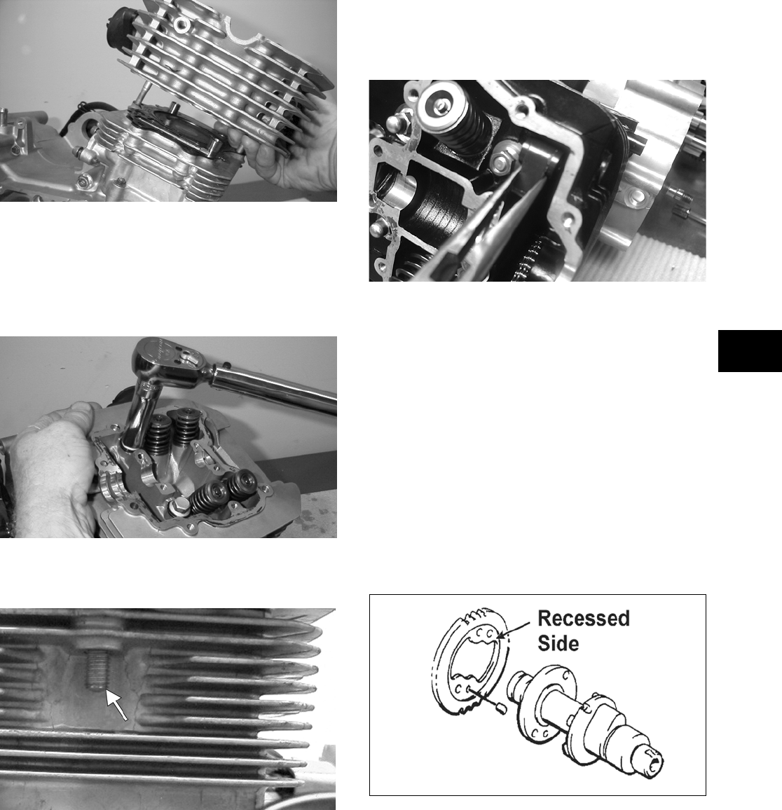
3-123
3
MD1163
7. Install the four cylinder head cap screws with
washers. Note that the two cap screws on the
right side of the cylinder head nearest the cam
sprocket are longer than the two cap screws on
the left (spark plug) side. Tighten only until
snug.
MD1270
8. Install the two lower nuts securing the cylinder
head to the cylinder, one in front and one in rear.
MD1192
9. In a crisscross pattern, tighten the four cylinder
head cap screws (from step 7) to specifications.
Tighten the two lower cylinder head nuts (from
step to specifications and the cylin-
der-to-crankcase nuts (from step 4) to specifica-
tions.
10. With the timing inspection plug removed and
the cam chain held tight, rotate the crankshaft
until the piston is at top-dead-center.
11. While holding the cam chain sprocket to the
side, install the rear cam chain tensioner guide
into the cylinder head. Install the pivot cap
screw and washer.
CD383
12. With the alignment pin installed in the camshaft
and the cam lobes directed down (toward the
piston), place the camshaft in position and verify
that the timing mark on the magneto is visible
through the inspection plug and that the timing
marks on the camshaft sprocket are parallel with
the valve cover mating surface.
NOTE: When the camshaft assembly is seated,
make sure the alignment pin in the camshaft aligns
with the smallest hole in the sprocket.
13. With the alignment pin installed in the camshaft,
loosely place the cam sprocket (with the
recessed side facing the camshaft lobes) onto the
camshaft and place it into position with the cam
chain over the sprocket.
MD1359
14. Place the C-ring into position in its groove in the
cylinder head.
FOR ARCTIC CAT ATV DISCOUNT PARTS CALL 606-678-9623 OR 606-561-4983
www.mymowerparts.com
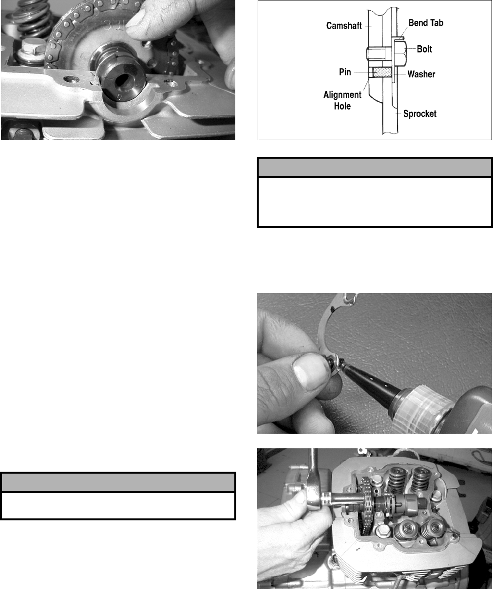
3-124
MD1131
NOTE: At this point, oil the camshaft bearings,
cam lobes, and the three seating journals on the
cylinder.
NOTE: Note the position of the alignment marks
on the end of the camshaft. They must be parallel
with the valve cover mating surface. If rotating the
camshaft is necessary for alignment, do not allow
the chain and sprocket to rotate and be sure the
cam lobes end up in the down position.
15. When the camshaft assembly is seated, ensure
the following.
A. Piston still at top-dead-center.
B. Camshaft lobes directed down (toward the
piston).
C. Camshaft alignment marks parallel to the
valve cover mating surface.
D. Recessed side of the sprocket directed toward
the cam lobes.
E. Camshaft alignment pin and sprocket align-
ment hole (smallest) are aligned.
16. Place the tab washer onto the sprocket making
sure it covers the pin in the alignment hole.
MD1363
17. Apply red Loctite #271 to the first cap screw
securing the sprocket and tab washer to the cam-
shaft; then install the cap screw and tab washer.
Tighten cap screw only until snug.
CC404D
MD1137
18. Rotate the crankshaft until the second cap screw
securing the sprocket to the camshaft can be
installed; then install the cap screw (threads
coated with red Loctite #271). Tighten to speci-
fications; then bend the tab to secure the cap
screw.
! CAUTION
If any of the above factors are not as stated, go back
to step 13 and carefully proceed.
! CAUTION
Care must be taken that the tab washer is installed
correctly to cover the alignment hole on the
sprocket. If the alignment pin falls out, severe
engine damage will result.
FOR ARCTIC CAT ATV DISCOUNT PARTS CALL 606-678-9623 OR 606-561-4983
www.mymowerparts.com
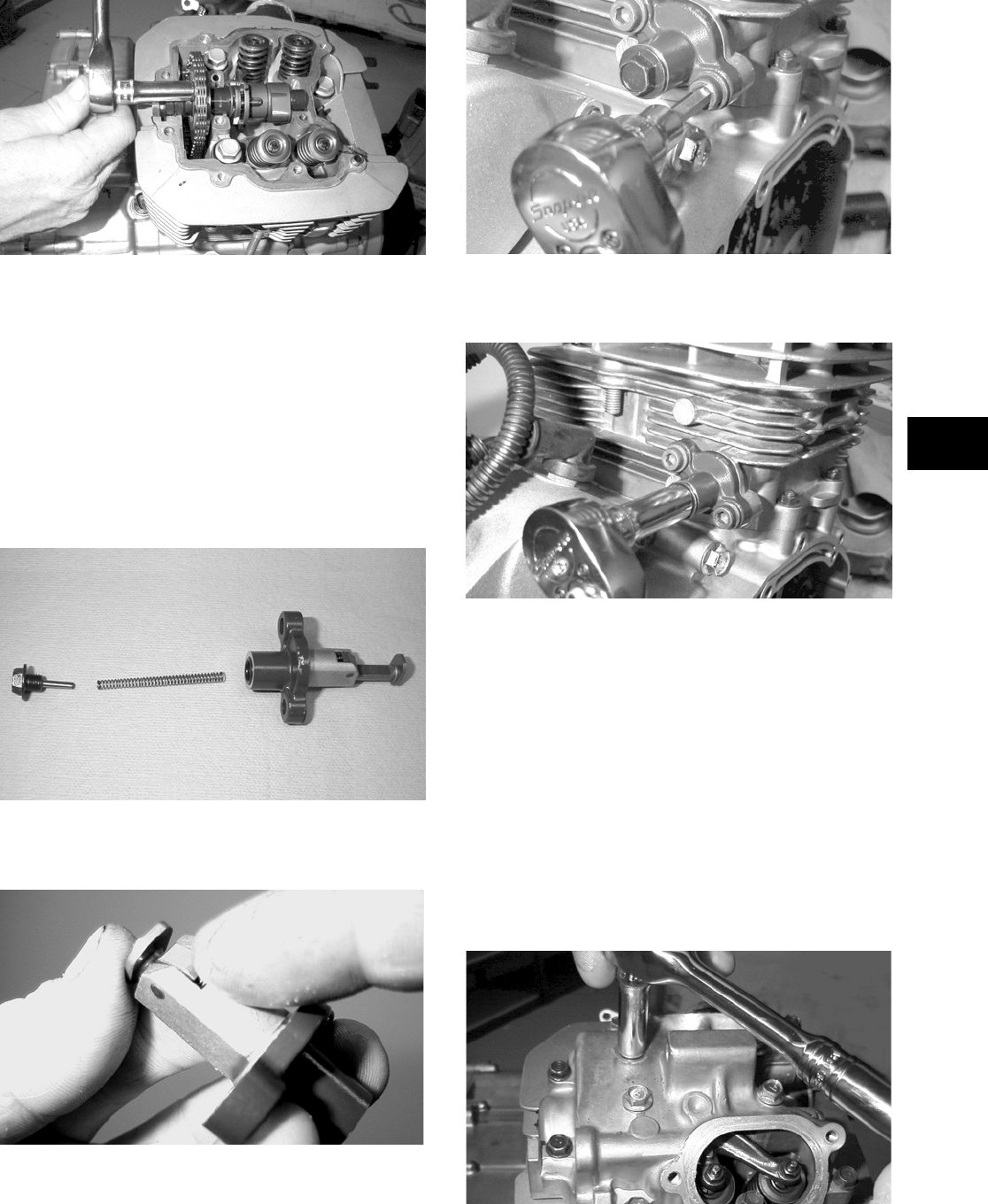
3-125
3
MD1137
19. Rotate the crankshaft until the first cap screw
(from step 17) securing the sprocket to the cam-
shaft can be addressed; then tighten to specifica-
tions. Bend the tab to secure the cap screw.
20. Install the cylinder head plug with the cupped
end facing the camshaft and the opening
directed downwards.
21. Remove the cap screw from the end of the chain
tensioner. Account for the plunger, spring, and
O-ring.
MD1248
22. Depress the spring-loaded lock and push the
plunger into the tensioner.
MD1146
23. Place the cam chain tensioner assembly and gas-
ket into the cylinder making sure the ratchet side
is facing toward the top of the cylinder and
secure with the two Allen-head screws.
MD1254
24. Install the cap screw and spring into the end of
the cam chain tensioner. Tighten securely.
MD1245
25. Loosen the adjuster screw jam nuts; then loosen
the adjuster screws on the rocker arms in the
valve cover.
26. Apply a thin coat of Three Bond Sealant to the
mating surface of the valve cover; then place the
valve cover into position. Note that the two
alignment pins are properly positioned.
NOTE: At this point, the rocker arms and
adjuster screws must not have pressure on them.
27. Install the four top-side cap screws with rubber
washers; then install the remaining cap screws.
Tighten only until snug.
MD1261
FOR ARCTIC CAT ATV DISCOUNT PARTS CALL 606-678-9623 OR 606-561-4983
www.mymowerparts.com
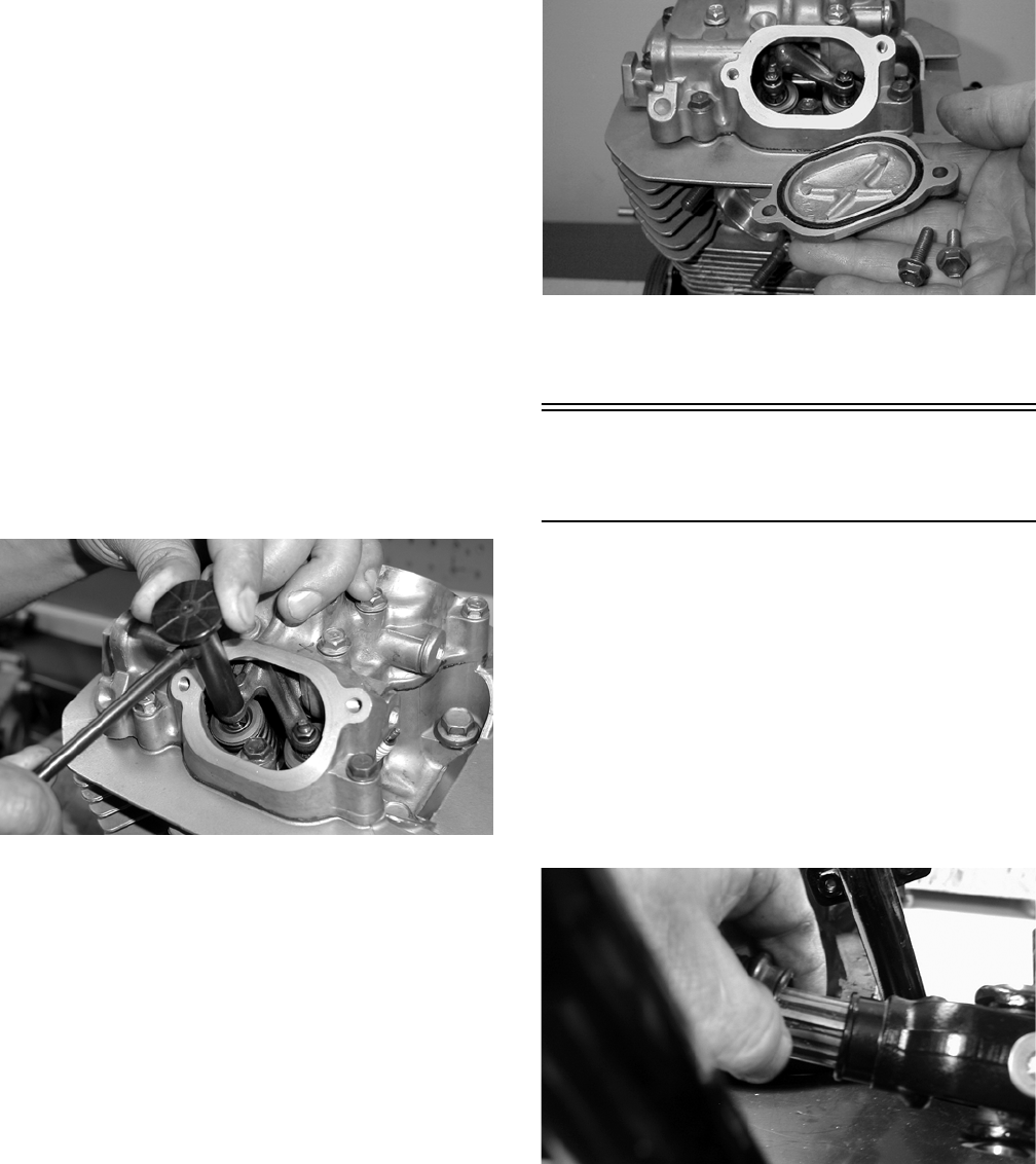
3-126
28. In a crisscross pattern starting from the center
and working outward, tighten the cap screws
(from step 27) to specifications.
29. Adjust valve/tappet clearance using the follow-
ing procedure.
NOTE: Use Valve Clearance Adjuster (p/n
0444-078) for this procedure.
A. Turn the engine over until the piston reaches
top-dead-center on the compression stroke.
B. Place the valve adjuster onto the jam nut
securing the tappet adjuster screw; then rotate
the valve adjuster dial clockwise until the end
is seated in the tappet adjuster screw.
C. While holding the valve adjuster dial in
place, use the valve adjuster handle and
loosen the jam nut; then rotate the tappet
adjuster screw clockwise until friction is felt.
CD001
D. Align the valve adjuster handle with one of
the marks on the valve adjuster dial.
E. While holding the valve adjuster handle in
place, rotate the valve adjuster dial counter-
clockwise until specified valve/tappet clear-
ance is attained.
NOTE: Rotating the valve adjuster dial counter-
clockwise will open the valve/tappet clearance by
0.05 mm (0.002 in.) per mark.
F. While holding the adjuster dial at the proper
clearance setting, tighten the jam nut securely
with the valve adjuster handle.
30. Place the two tappet covers with O-rings into
position; then install and tighten the cap screws
securely.
MD1264
31. Install the spark plug and tighten to specifica-
tions; then install the timing inspection plug.
Installing
Engine/Transmission
NOTE: Arctic Cat recommends that new gaskets
and O-rings be installed whenever servicing the
ATV.
1. From the left side, place the engine/transmission
into the frame; then slide the engine rearward as
far as possible.
2. Slightly raise the rear of the engine and engage
the front drive coupler into the splines of the
front drive output yoke; then slide the engine
forward as far as possible.
CD818
3. Raise the rear of the engine and place a block
beneath it; then install the propeller shaft and
output flange into the rear drive coupler.
FOR ARCTIC CAT ATV DISCOUNT PARTS CALL 606-678-9623 OR 606-561-4983
www.mymowerparts.com
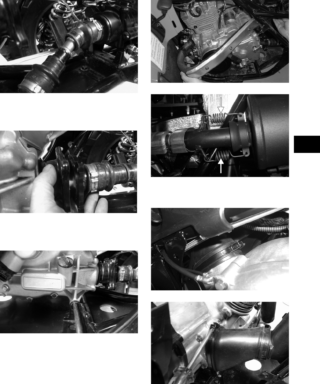
3-127
3
CD821
4. Remove the block from beneath the engine; then
align the rear drive flanges and secure with four
cap screws. Tighten to specifications.
CD824
5. Install two engine mounting through-bolts, two
bushings, and two washers; then tighten the
through-bolt flange nuts to specifications.
CD809
6. Secure the exhaust pipe to the engine with two
cap screws; then install the muffler and the
exhaust springs.
CC941
CF138A
7. Install the cooling ducts with clamps and tighten
the clamps securely.
CD515
CD793
8. Secure the engine ground wire to the engine
with a cap screw. Tighten to specifications.
FOR ARCTIC CAT ATV DISCOUNT PARTS CALL 606-678-9623 OR 606-561-4983
www.mymowerparts.com
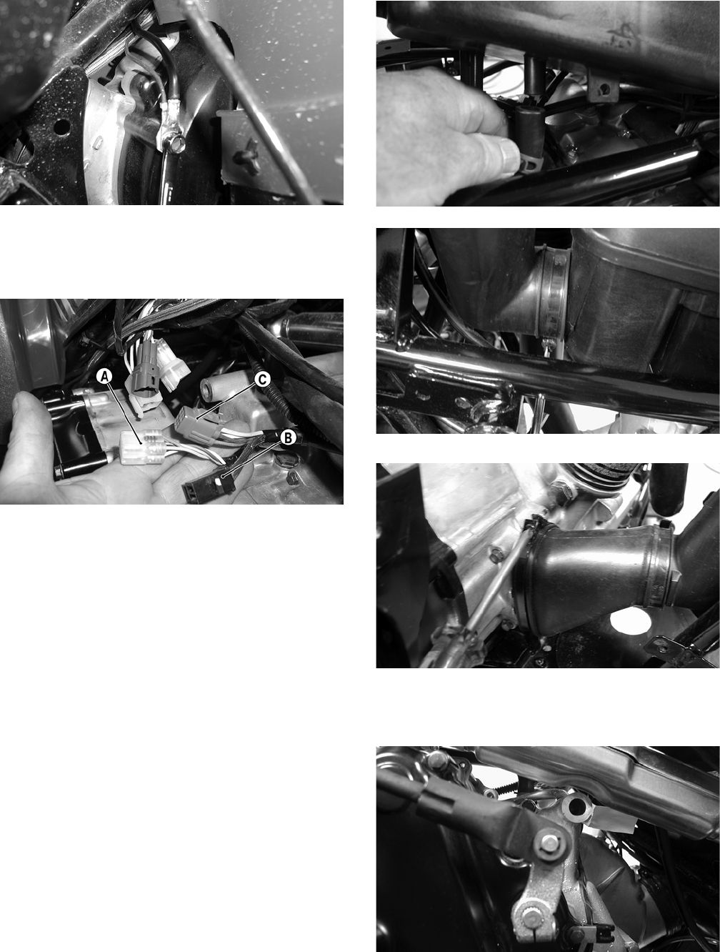
3-128
CD810
9. Connect the gear position indicator connector
(A), stator connector (B), and the CDI connector
(C) to the main wiring harness.
CD797A
10. Connect the temperature sensor leads to the
main wiring harness.
11. Secure the wires to the frame with nylon ties.
12. Connect the speed sensor lead to the wiring har-
ness.
13. Secure the positive cable to the starter motor.
14. Secure all wiring to the frame and upper engine
bracket with cable ties.
15. Secure the two oil hoses to the engine.
16. Secure the crankcase vent hose to the air cleaner
housing; then secure the inlet boot and carbure-
tor to the air cleaner housing.
CD787
CD785
CD793
17. Secure the shift rod to the engine with a new
E-clip.
CD774
18. Install the front and rear body panels; then install
the front and rear racks (see Section 8).
FOR ARCTIC CAT ATV DISCOUNT PARTS CALL 606-678-9623 OR 606-561-4983
www.mymowerparts.com
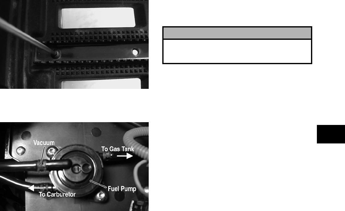
3-129
3
19. Install the left-side foot peg to the footrest.
Tighten securely.
CD782
20. Connect the hose to the fuel pump; then connect
the vacuum hose and secure with hose clamps.
CD766A
21. Place the storage compartment into position;
then install the reinstallable rivets.
22. Place the battery into position in the battery
compartment; then install the battery cables and
vent hose. Secure with the battery cover.
23. Add proper amounts of engine/transmission oil.
24. Install the seat.
! CAUTION
Battery acid is harmful if it contacts eyes, skin, or
clothing. Care must be taken whenever handling a
battery.
FOR ARCTIC CAT ATV DISCOUNT PARTS CALL 606-678-9623 OR 606-561-4983
www.mymowerparts.com
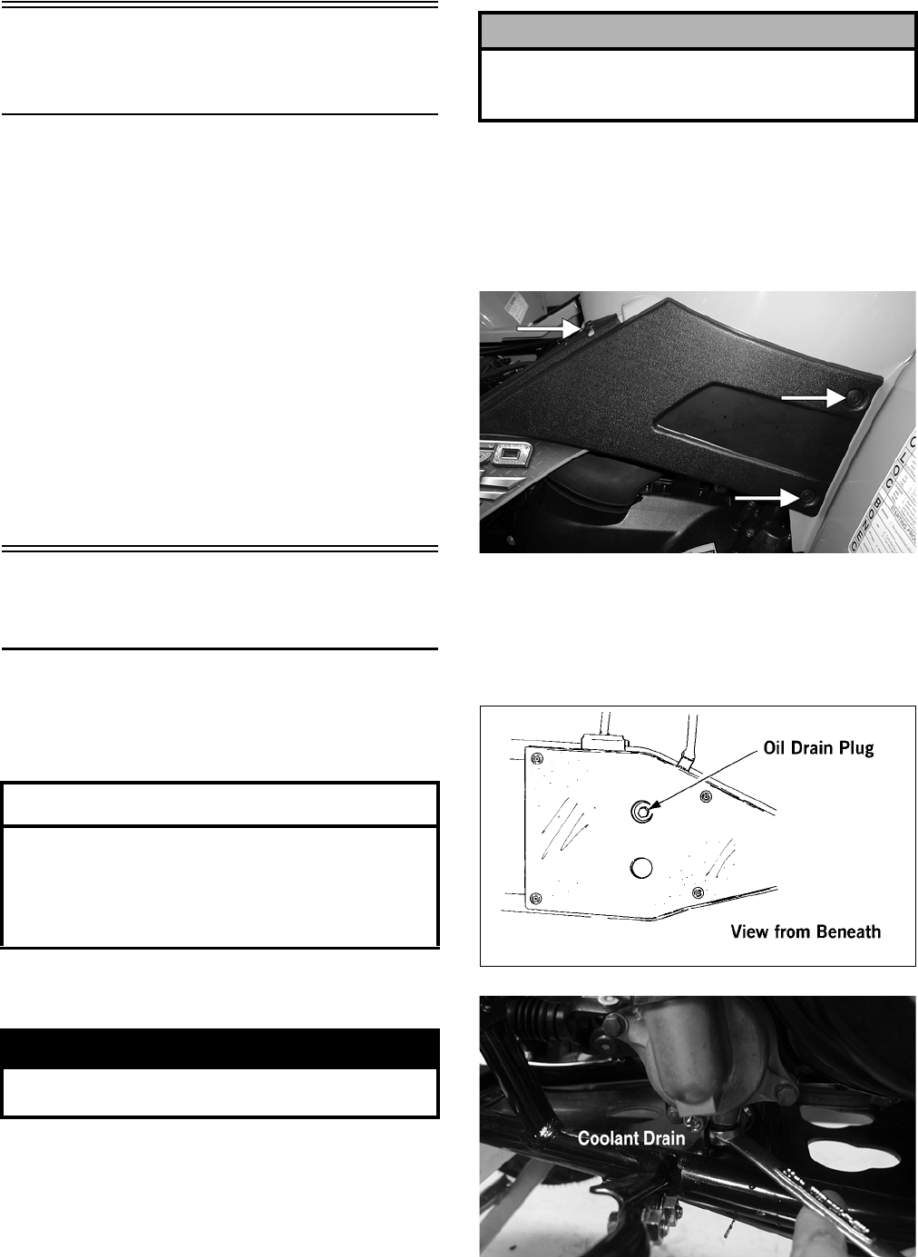
3-130
Table of Contents
(500 — Automatic Transmission/
650 H1)
Removing Engine/Transmission ……………………. 3-130
Top-Side Components……………….…………….…… 3-134
Removing Top-Side Components …….……………. 3-134
Left-Side Components ……………………….………… 3-138
Removing Left-Side Components ….…………….… 3-138
Right-Side Components …………….………….……… 3-141
Removing Right-Side Components…..……………. 3-141
Center Crankcase Components ……………………. 3-145
Separating Crankcase Halves………….……………. 3-145
Disassembling Crankcase Half ……………………… 3-145
Servicing Components………..……………..………… 3-147
Assembling Crankcase Half ………………..………… 3-166
Joining Crankcase Halves……………….………….… 3-168
Installing Right-Side Components…….……………. 3-169
Installing Left-Side Components …………….……… 3-172
Installing Top-Side Components ………………….… 3-175
Installing Engine/Transmission…………….………… 3-181
Removing Engine/
Transmission
Many service procedures can be performed without
removing the engine/transmission from the frame.
Closely observe the note introducing each sub-sec-
tion for this important information.
Secure the ATV on a support stand to elevate the
wheels.
1. Remove the seat.
2. Remove the negative cable from the battery;
then remove the positive cable. Remove the bat-
tery and the battery vent hose; then remove the
battery.
3. Remove the radiator access cover, steering post
cover, and storage compartment cover assem-
bly; then remove the storage compartment box.
4. Remove the reinstallable rivets securing the side
panels; then remove the panels.
CD683A
5. Remove the instrument pod; then remove the
front rack and front body panel (see Section 8).
6. Drain the oil from beneath the engine/transmis-
sion; then drain the coolant.
733-441A
CD799A
7. Remove the air filter (see Section 2).
AT THIS POINT
If the technician’s objective is to service/replace
left-side cover oil seals (3), front output joint oil
seal (1), rear output joint oil seal (1), and/or the oil
strainer (from beneath the engine/transmission),
the engine/transmission does not have to be
removed from the frame.
! WARNING
Make sure the ATV is solidly supported on the sup-
port stand to avoid injury.
! CAUTION
Battery acid is harmful if it contacts eyes, skin, or
clothing. Care must be taken whenever handling a
battery.
FOR ARCTIC CAT ATV DISCOUNT PARTS CALL 606-678-9623 OR 606-561-4983
www.mymowerparts.com
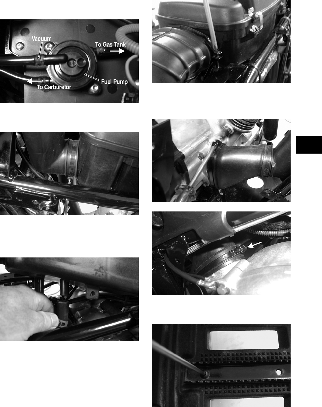
3-131
3
8. Remove the vacuum hose and the fuel-pump-
to-carburetor hose.
CD766A
9. Loosen the clamp securing the air intake duct to
the air filter housing.
CD785
10. Disconnect the crankcase vent hose from the air
filter housing. Remove the clamp securing the
carburetor intake duct to the air filter housing;
then remove the air filter housing.
CD787
CD786
11. Remove the clamp securing the cooling duct boot
to the V-belt housing; then remove the cooling
duct boot from the V-belt housing outlet.
CD793
CD515A
12. Remove the left-side foot peg and footwell (see
Section 8).
CD782
FOR ARCTIC CAT ATV DISCOUNT PARTS CALL 606-678-9623 OR 606-561-4983
www.mymowerparts.com
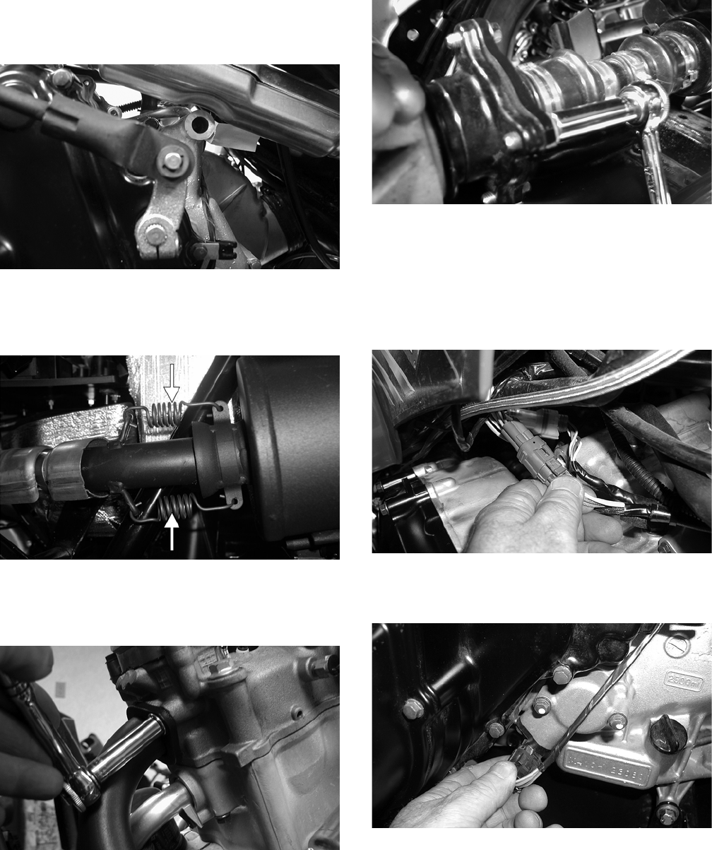
3-132
13. Secure the carburetor assembly up and away
from the engine.
14. Remove the E-clip securing the shift rod to the
engine shift arm; then allow the shift rod to
swing forward and hang straight down from the
shift lever.
CD774
15. Remove the springs securing the muffler to the
exhaust pipe; then remove the muffler. Account
for the two exhaust springs.
CF138A
16. Remove the two cap screws securing the
exhaust pipe to the cylinder head; then remove
the pipe.
CD803
17. Remove the two coolant hoses from the engine;
then route the hoses out of the way.
18. Remove the cap screws securing the rear drive-
shaft/output flange to the rear output joint
flange.
CD805
NOTE: It is advisable to lock the brake when
loosening the cap screws securing the rear drive-
shaft.
19. Remove the positive cable from the starter
motor and route it out of the way.
CD796
20. Disconnect the speed sensor connector from the
sensor housing.
CD794
21. On the right-side, disconnect the gear position
indicator connector (A), stator connector (B),
and the CDI connector (C).
FOR ARCTIC CAT ATV DISCOUNT PARTS CALL 606-678-9623 OR 606-561-4983
www.mymowerparts.com
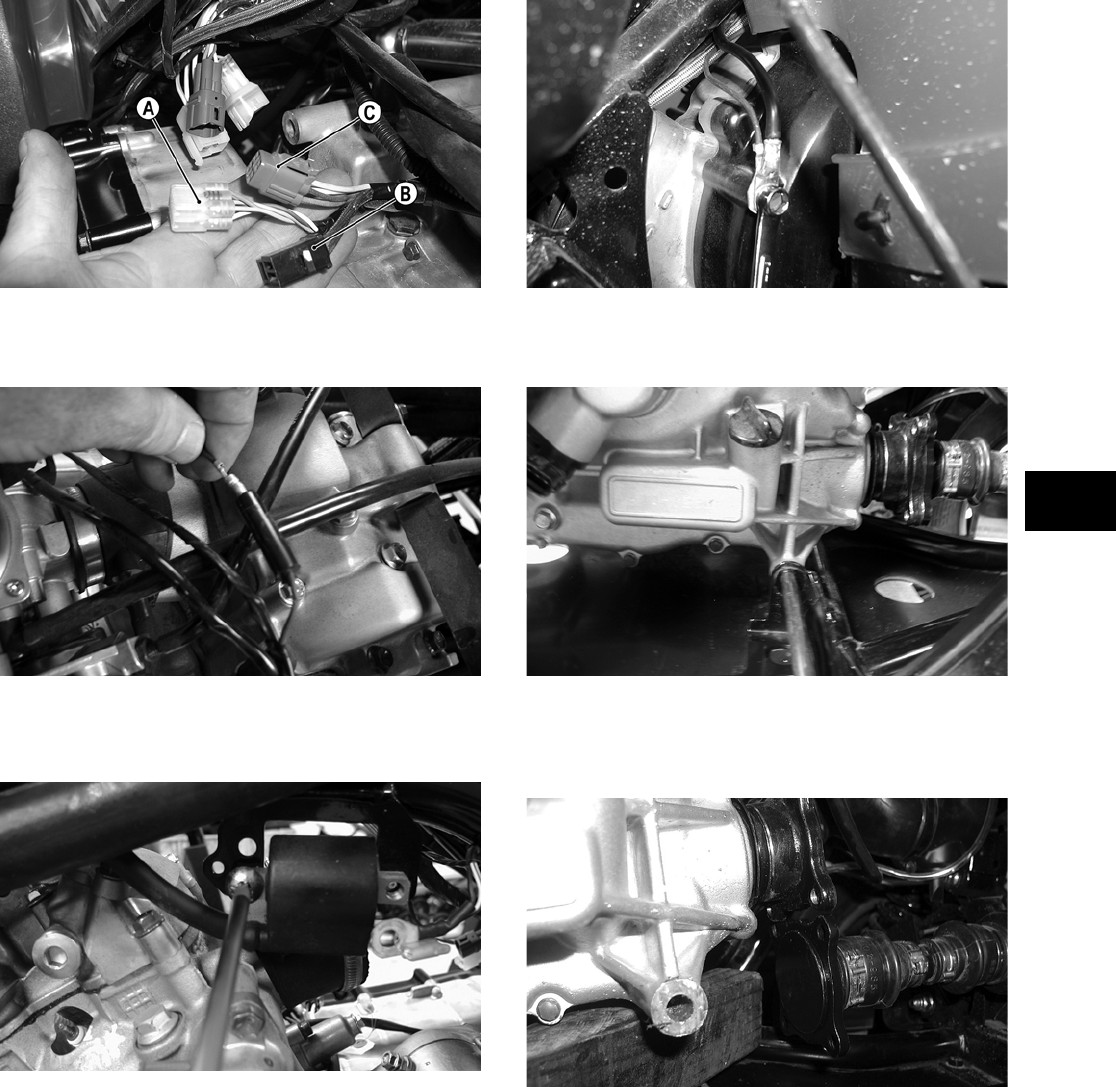
3-133
3
CD797A
22. Disconnect the temperature sensor lead from the
wiring harness.
CD788
23. Remove the spark plug wire from the spark
plug; then remove the coil from the frame.
CD814
24. Remove the cap screw securing the engine
ground wire to the engine.
CD810
25. Remove the two engine mounting through-bolts.
Account for a washer and a spacer on the bolts.
CD809
26. Raise the rear of the engine enough to allow the
rear output flange to clear the output flange
joint. Block the engine up in this position.
CD811
27. Remove the first small boot clamp; then remove
the output flange and driveshaft from the rear
drive coupler.
FOR ARCTIC CAT ATV DISCOUNT PARTS CALL 606-678-9623 OR 606-561-4983
www.mymowerparts.com
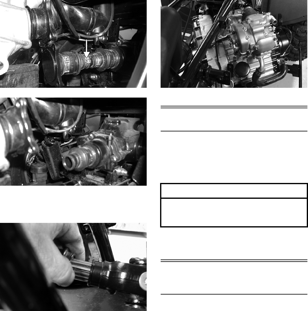
3-134
CD812A
CD813
28. Remove the block from under the engine and
lower the engine; then remove the boot clamp
from the front output drive yoke.
CD818
29. Move the engine to the rear enough to allow the
front driveshaft to clear the front output yoke;
then move the engine forward and to the left.
The engine will come out the left side of the
frame.
CD773
Top-Side Components
NOTE: For efficiency, it is preferable to remove
and disassemble only those components which
need to be addressed and to service only those
components. The technician should use discretion
and sound judgment.
NOTE: The engine/transmission does not have
to removed from the frame for this procedure.
Removing Top-Side
Components
A. Valve Cover
B. Cylinder Head
NOTE: Remove the spark plug and timing
inspection plug; then using the recoil starter,
rotate the crankshaft to top-dead-center of the
compression stroke.
1. Remove the two tappet covers.
AT THIS POINT
To service any one specific component, only
limited disassembly of components may be
necessary. Note the AT THIS POINT information in
each sub-section.
FOR ARCTIC CAT ATV DISCOUNT PARTS CALL 606-678-9623 OR 606-561-4983
www.mymowerparts.com
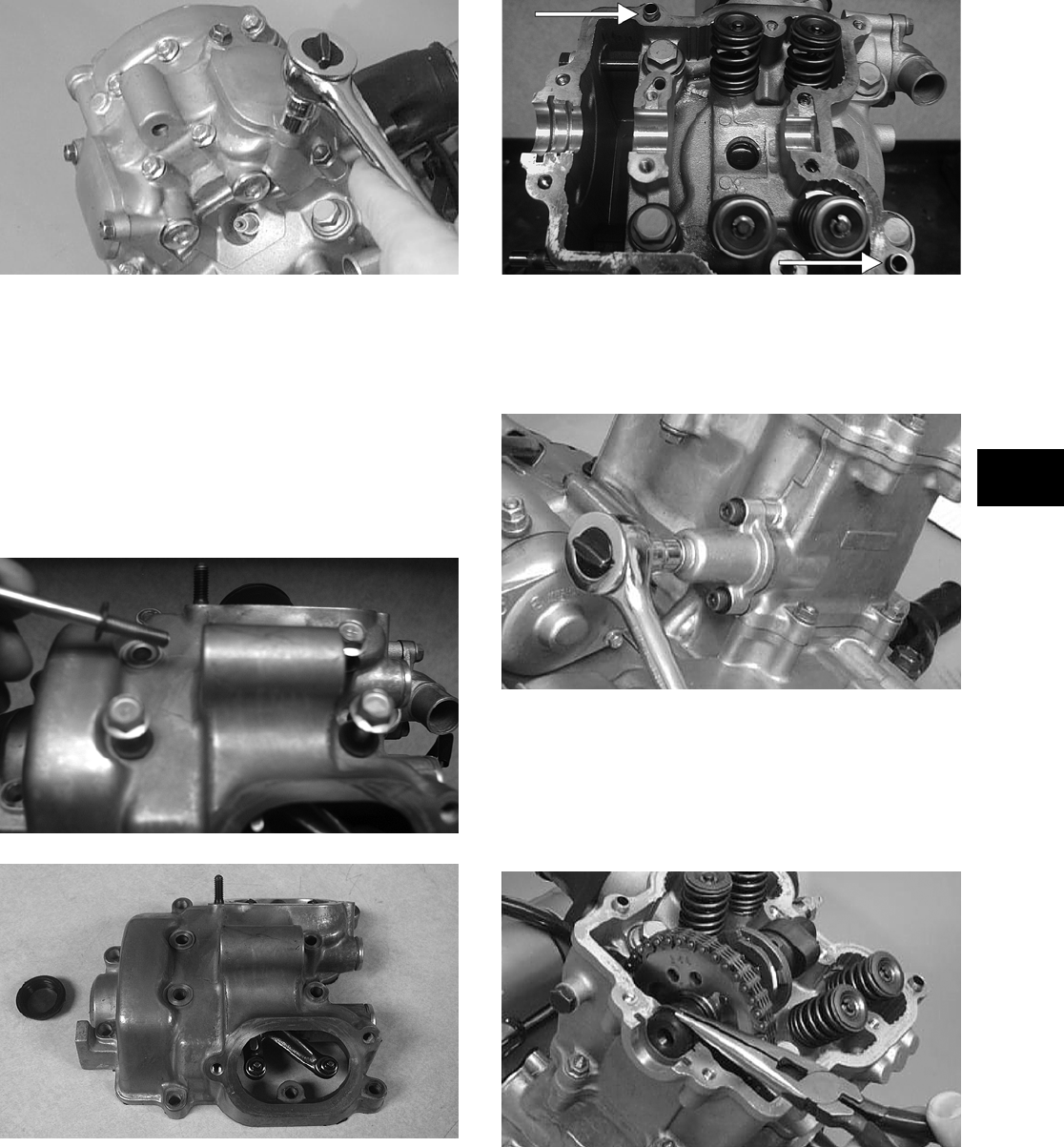
3-135
3
CC001D
NOTE: Keep the mounting hardware with the
covers for assembly purposes or thread them back
into the head to keep them separated.
2. Remove the 12 cap screws securing the valve
cover to the head; account for the four rubber
washers on the top side cap screws. Remove the
valve cover. Account for and note the orienta-
tion of the cylinder head plug. Note the location
of two alignment pins.
CD205
CD206
CD211A
3. Loosen the cap screw on the end of the ten-
sioner; then remove the two Allen-head cap
screws securing the tensioner adjuster assembly
and remove the assembly. Account for a gasket.
CC009D
4. Using an awl, rotate the C-ring in its groove
until it is out of the cylinder head; then remove
the C-ring.
NOTE: Care should be taken not to drop the
C-ring down into the crankcase.
CC012D
5. Bend the washer tabs down and remove the two
cap screws securing the sprocket to the cam-
shaft; then drop the sprocket off the camshaft.
FOR ARCTIC CAT ATV DISCOUNT PARTS CALL 606-678-9623 OR 606-561-4983
www.mymowerparts.com
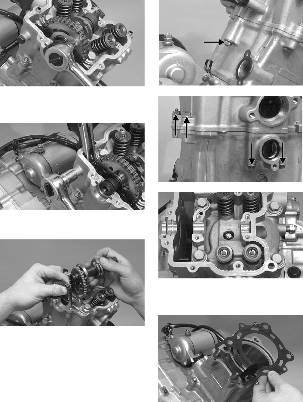
3-136
CC013D
6. Remove the cap screw securing the chain ten-
sioner (account for a washer); then remove the
tensioner.
CC014D
7. While holding the chain, slide the sprocket and
camshaft out of the cylinder head.
CC266D
NOTE: Loop the chain over the cylinder and
secure it to keep it from falling into the crankcase.
8. Remove the five nuts securing the cylinder head
to the cylinder; then remove the four cylinder
head cap screws with copper washers (note loca-
tion of the different-sized cap screws and nuts).
CC017D
CC018D
CC016D
9. Remove the cylinder head from the cylinder,
remove the gasket, and account for two align-
ment pins; then remove the cam chain guide.
CC020D
FOR ARCTIC CAT ATV DISCOUNT PARTS CALL 606-678-9623 OR 606-561-4983
www.mymowerparts.com
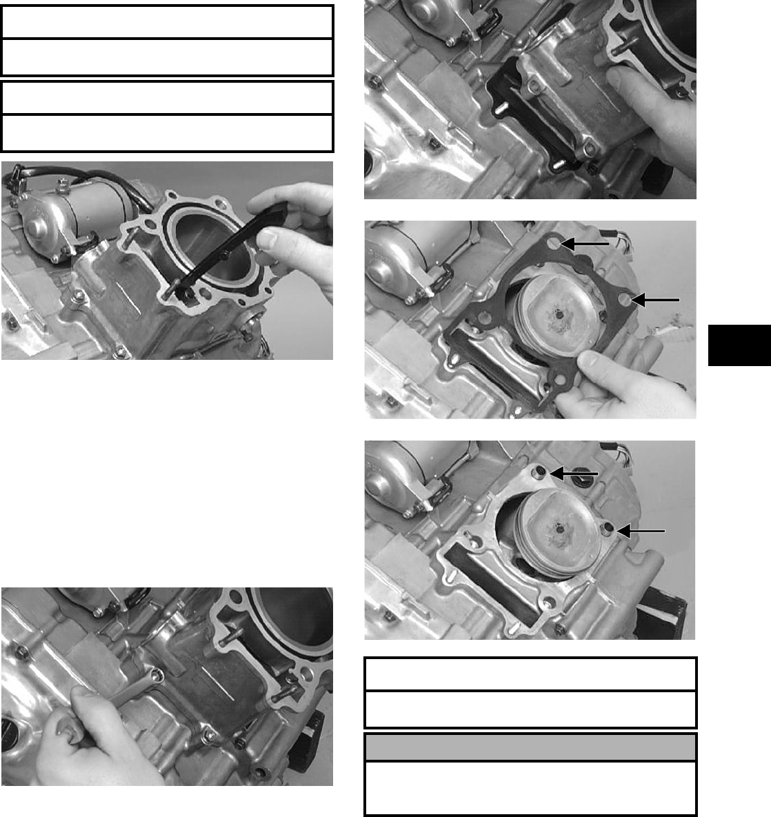
3-137
3
CC022D
C. Cylinder
D. Piston
NOTE: Steps 1-9 in the preceding sub-section
must precede this procedure.
10. Loosen the clamp securing the coolant hose to
the union; then detach the hose.
11. Remove the two nuts securing the cylinder to
the crankcase.
CC023D
12. Lift the cylinder off the crankcase taking care
not to allow the piston to drop against the crank-
case. Account for the gasket and two alignment
pins.
CC024D
CC025D
CC026D
13. Using an awl, remove one piston-pin circlip.
AT THIS POINT
To service valves and cylinder head, see
Servicing Top-Side Components sub-section.
AT THIS POINT
To inspect cam chain guide, see Servicing
Top-Side Components sub-section.
AT THIS POINT
To service cylinder, see Servicing Top-Side
Components sub-section.
! CAUTION
When removing the cylinder, be sure to support the
piston to prevent damage to the crankcase and pis-
ton.
FOR ARCTIC CAT ATV DISCOUNT PARTS CALL 606-678-9623 OR 606-561-4983
www.mymowerparts.com
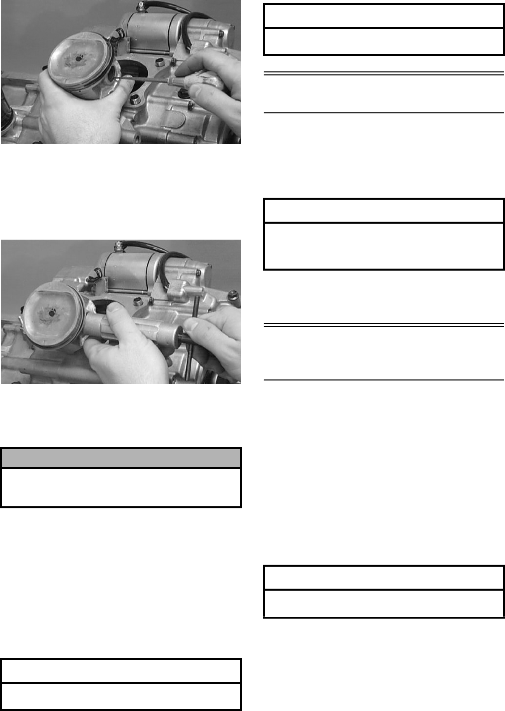
3-138
CC032D
14. Using the Piston Pin Puller (p/n 0644-328),
remove the piston pin. Account for the oppo-
site-side circlip. Remove the piston.
NOTE: It is advisable to remove the oppo-
site-side circlip prior to using the puller.
CC033D
NOTE: Support the connecting rod with rubber
bands to avoid damaging the rod or install the
Connecting Rod Holder (p/n 0444-006).
NOTE: If the existing rings will not be replaced
with new rings, note the location of each ring for
proper installation. When replacing with new rings,
replace as a complete set only. If the piston rings
must be removed, remove them in this sequence.
A. Starting with the top ring, slide one end of the
ring out of the ring-groove.
B. Remove each ring by working it toward the dome
of the piston while rotating it out of the groove.
Left-Side Components
NOTE: For efficiency, it is preferable to remove
and disassemble only those components which
need to be addressed and to service only those
components. The technician should use discretion
and sound judgment.
NOTE: The engine/transmission does not have
to be removed from the frame for this procedure.
Removing Left-Side
Components
A. Recoil Starter/Outer Magneto
Cover
B. Water Pump
C. Cover
D. Rotor/Flywheel
NOTE: The 500 and certain 650 H1 models are
equipped with a recoil starter.
1. Remove the four cap screws securing the recoil
starter/outer magneto cover to the left-side
cover; then remove the recoil starter/outer mag-
neto cover. Account for the gasket.
2. Remove the flange nut securing the starter
cup/spacer to the crankshaft; then remove the
starter cup/spacer. Account for the O-ring inside
the cup.
! CAUTION
Do not allow the connecting rod to go down inside the
crankcase. If the rod is down inside the crankcase and
the crankshaft is rotated, severe damage will result.
AT THIS POINT
To service piston, see Servicing Top-Side
Components sub-section.
AT THIS POINT
To service center crankcase components only,
proceed to Removing Left-Side Components.
AT THIS POINT
To service any one specific component, only
limited disassembly of components may be
necessary. Note the AT THIS POINT information in
each sub-section.
AT THIS POINT
To service the recoil starter, see Servicing Left-Side
Components sub-section.
FOR ARCTIC CAT ATV DISCOUNT PARTS CALL 606-678-9623 OR 606-561-4983
www.mymowerparts.com
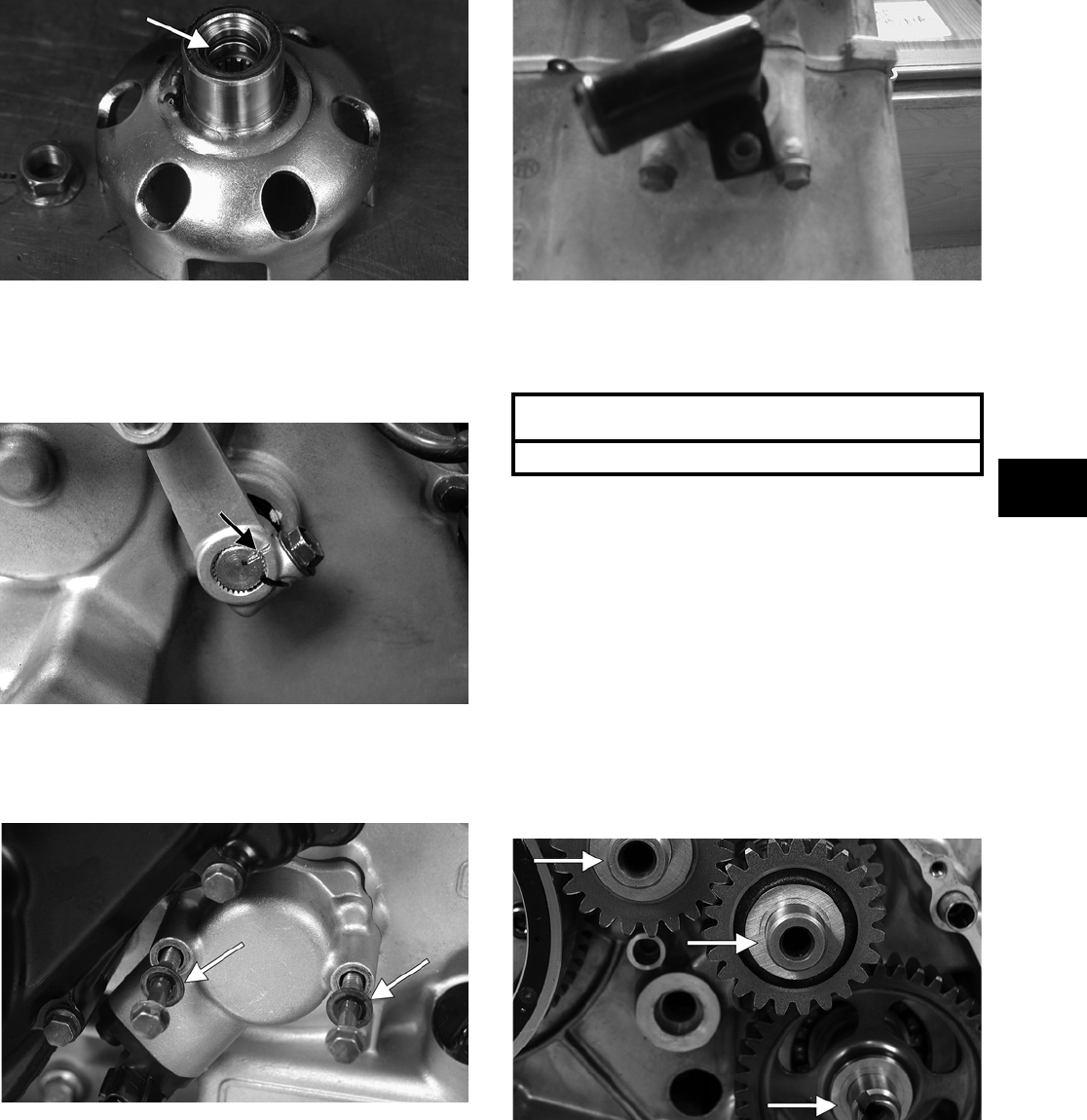
3-139
3
CD925A
3. Using a cold chisel, scribe a mark showing the
relative position of the shift arm to the shift arm
shaft to aid in installing; then remove the shift
arm.
FI085A
4. Remove the two cap screws securing the speed
sensor housing; then remove the housing.
Account for the gasket and two seal washers.
CD920A
5. Loosen the clamps securing the coolant hose to
the water pump; then remove the crossover tube
from the cylinder head. Account for an O-ring.
CD214
6. Remove the two cap screws securing the water
pump to the engine; then remove the water
pump.
7. Remove the cap screws securing the left-side
cover to the crankcase noting the location of the
different-sized cap screws for installing pur-
poses.
8. Using Side Case Puller (p/n 0644-262), remove
the side cover. Account for a gasket and two
alignment pins.
NOTE: Inspect the inside of the left-side cover
for any shaft washers that may have come off with
the cover. Make sure they are returned to their
respective shafts and that the starter idler gear
spacer is on the shaft or in the cover.
CF075A
9. Remove the nut securing the magneto rotor to
the crankshaft; then install the magneto rotor
puller adapter.
NOTE: The puller has left-hand threads.
10. Using Magneto Rotor Remover Set (p/n
0444-075), remove the rotor/flywheel assembly
from the crankshaft. Account for the key; then
remove the starter clutch gear assembly and
washer.
AT THIS POINT
To service the water pump, see Section 4.
FOR ARCTIC CAT ATV DISCOUNT PARTS CALL 606-678-9623 OR 606-561-4983
www.mymowerparts.com
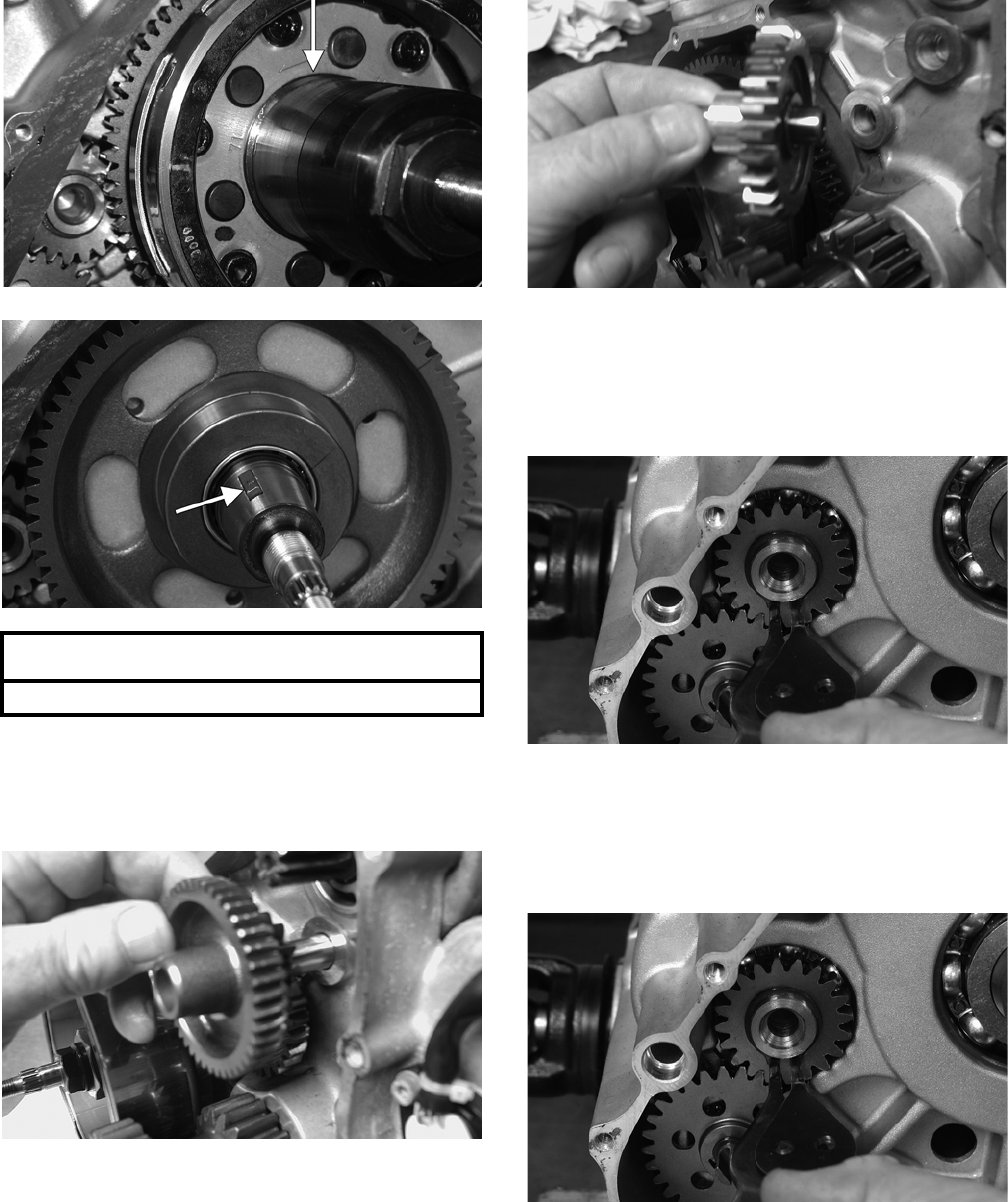
3-140
CD939A
CD940A
11. Remove the two starter gears from the crankcase
noting the direction of the beveled side of the
gears for installing purposes; then remove the
two starter gear shafts.
CD136
CD140
12. Remove the snap ring securing the water pump
drive gear; then remove the gear noting the
direction of the sides of the gear for installing
purposes. Account for the drive gear alignment
pin.
CD944
13. Remove the snap ring securing the water pump
driven gear; then remove the gear noting the
direction of the sides of the gear for installing
purposes. Account for the driven gear alignment
pin.
CD952A
NOTE: There is an oil passage beneath the
driven gear/drive gear assembly. This passage
should be plugged prior to removing the driven
gear and drive gear. Failure to do so could result in
the loss of an alignment pin into the crankcase.
AT THIS POINT
To service the magneto assembly, see Section 5.
FOR ARCTIC CAT ATV DISCOUNT PARTS CALL 606-678-9623 OR 606-561-4983
www.mymowerparts.com
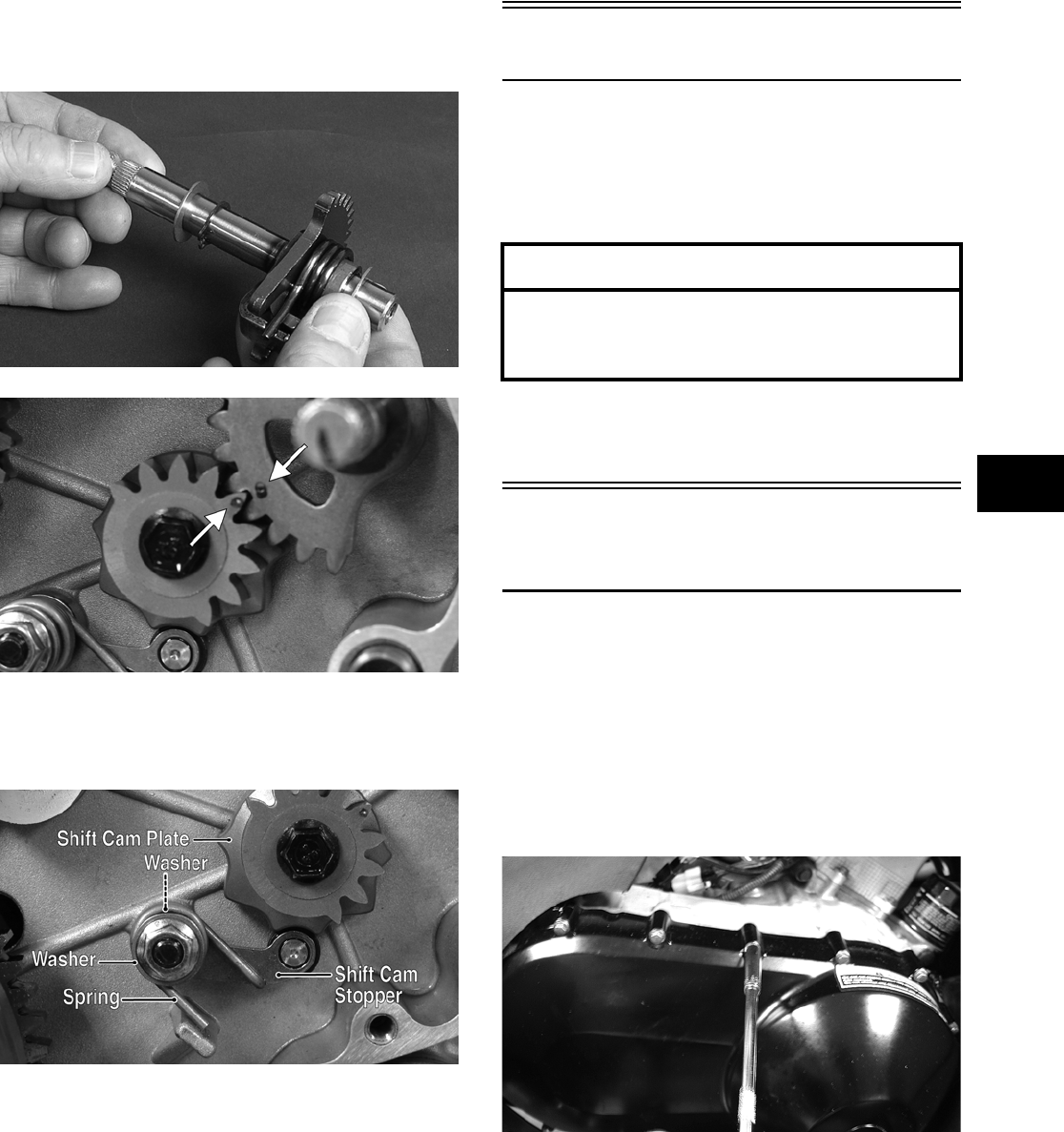
3-141
3
14. Remove the shift shaft noting the timing marks
for assembling purposes. Account for two wash-
ers.
FI302
PR430A
15. Remove the gear shift cam plate; then remove
the cam stopper and cam stopper spring.
Account for two washers.
PR434A
Right-Side Components
NOTE: For efficiency, it is preferable to remove
and disassemble only those components which
need to be addressed and to service only those
components. The technician should use discretion
and sound judgment.
NOTE: The engine/transmission does not have
to be removed from the frame for this procedure.
Removing Right-Side
Components
A. V-Belt Cover
B. Driven Pulley
C. Clutch Cover
1. Remove the cap screws securing the V-belt
cover noting the location of the differ-
ent-lengthed cap screws for installing purposes;
then using a rubber mallet, gently tap on the
cover tabs to loosen the cover.
CD079
2. Remove the nut securing the movable drive
face; then remove the face. Account for a spacer.
AT THIS POINT
To service any one specific component, only
limited disassembly of components may be
necessary. Note the AT THIS POINT information in
each sub-section.
FOR ARCTIC CAT ATV DISCOUNT PARTS CALL 606-678-9623 OR 606-561-4983
www.mymowerparts.com
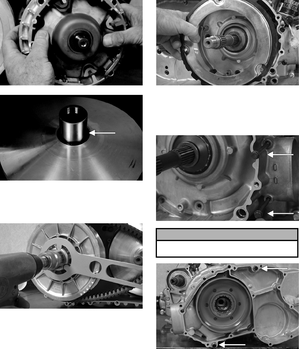
3-142
CD963
CD966A
3. Remove the V-belt.
4. Remove the nut securing the fixed driven
assembly; then remove the assembly.
PR388
5. Remove the fixed drive face.
6. Using an impact driver, remove the cap screws
securing the air intake plate; then remove the
plate cushion.
PR393
7. Remove the cap screws securing the clutch
cover. Note the location of the differ-
ent-lengthed cap screws for installing purposes.
Using a rubber mallet, carefully remove the
cover. Account for two alignment pins.
CD973A
CD974A
NOTE: For steps 8-14, refer to illustration
CC829B.
NOTE: To aid in installing, it is recommended that
the assemblies are kept together and IN ORDER.
! CAUTION
Care must be taken when removing the cover so the
cover gasket is not damaged.
FOR ARCTIC CAT ATV DISCOUNT PARTS CALL 606-678-9623 OR 606-561-4983
www.mymowerparts.com
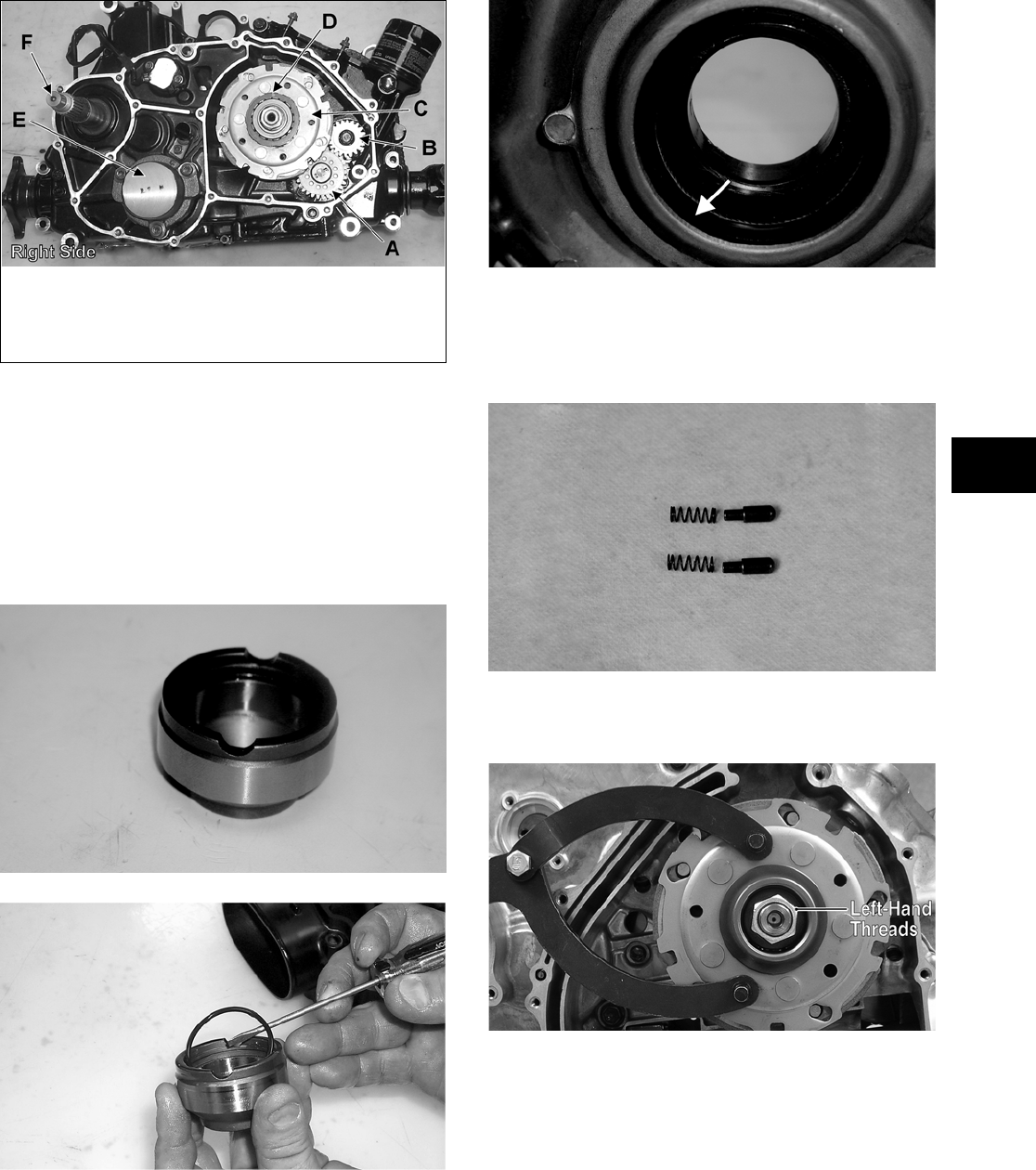
3-143
3
CC829B
8. Remove the one-way clutch (D) from the clutch
housing. Note the location of the green align-
ment dot (or the word OUTSIDE) for installing
purposes.
9. Using a hydraulic press, remove the clutch hous-
ing assembly from the clutch cover. Account for
the left fixed drive spacer and an O-ring inside
the fixed drive spacer.
CF085
CC596
NOTE: Account for and inspect the clutch hous-
ing seal.
CF088A
10. Remove the two Allen-head screws securing the
shift indicator sensor; then remove the sensor.
Account for two neutral contact pins and two
springs.
CD997
11. Remove the nut (left-hand threads) securing the
clutch shoe assembly (C). Account for a washer.
FI279A
NOTE: The washer is also directional. The flat
side of the washer must face toward the centrifu-
gal clutch assembly when installing.
KEY
A. Oil Pump Driven Gear
B. Oil Pump Drive Gear
C. Clutch Shoe Assembly
D. One-Way Clutch
(Green Dot MUST Show)
E. Final Drive Carrier Bearing
Housing
F. Input Shaft
FOR ARCTIC CAT ATV DISCOUNT PARTS CALL 606-678-9623 OR 606-561-4983
www.mymowerparts.com
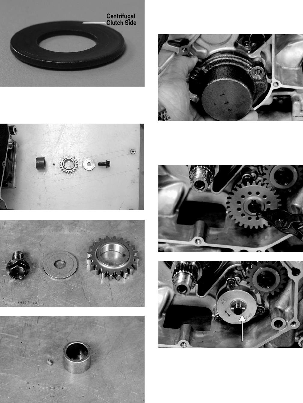
3-144
FI336A
12. Remove the cap screw securing the oil pump
drive gear (B). Account for a cap screw, washer,
pin, and spacer.
CC606
CD987
CD993
13. Using an impact driver, remove the Allen-head
screws securing the final drive carrier bearing
housing (E); then remove the housing and
account for two alignment pins.
CD999
14. Remove the snap ring securing the oil pump
driven gear (A); then remove the gear noting the
direction of the sides of the gear for installing
purposes. Account for a pin and a washer.
CD984
CD895A
15. Using an impact driver, remove the three Phil-
lips-head screws securing the oil pump; then
remove the pump.
FOR ARCTIC CAT ATV DISCOUNT PARTS CALL 606-678-9623 OR 606-561-4983
www.mymowerparts.com
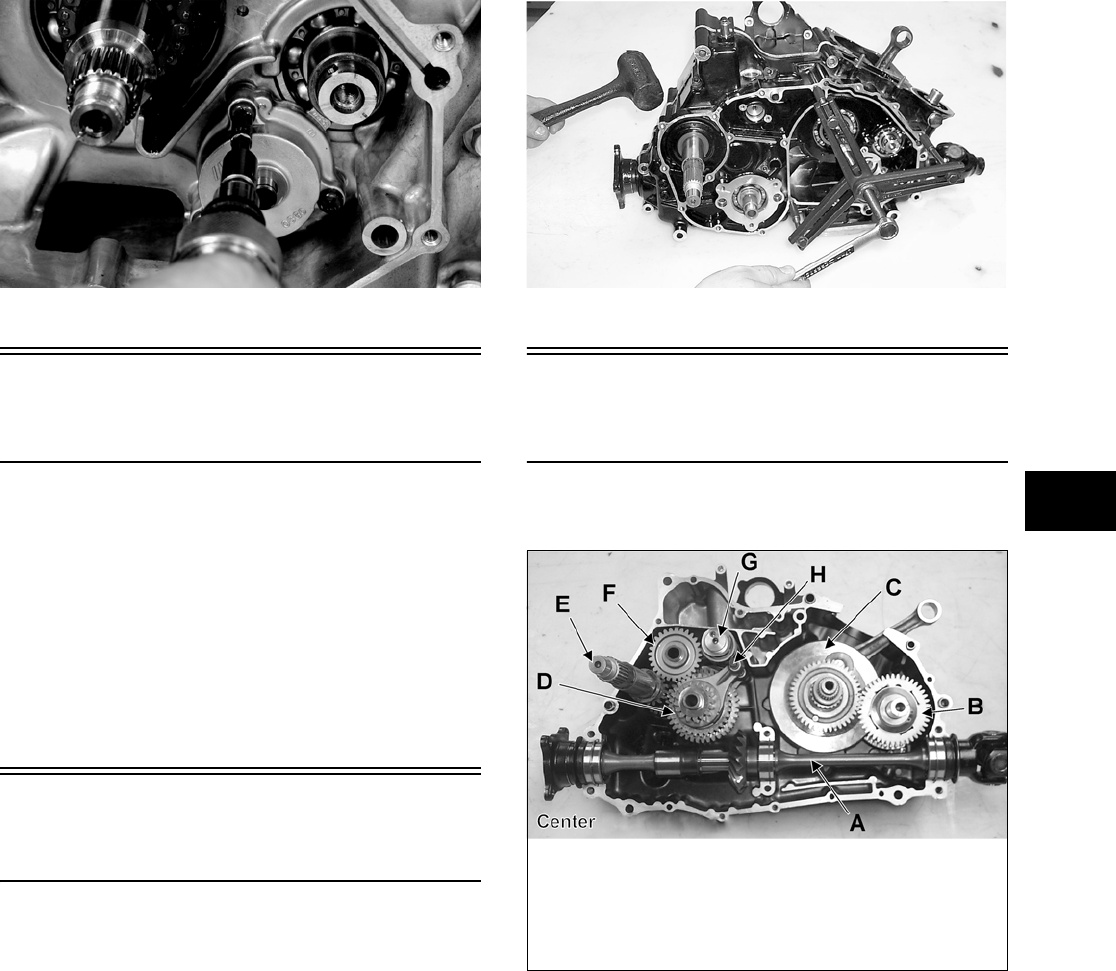
3-145
3
CD988
Center Crankcase
Components
NOTE: This procedure cannot be done with the
engine/transmission in the frame. Complete
Removing procedures for Top-Side, Left-Side, and
Right-Side must precede this procedure.
NOTE: For efficiency, it is preferable to remove
and disassemble only those components which
need to be addressed and to service only those
components. The technician should use discretion
and sound judgment.
Separating Crankcase
Halves
1. Remove the right-side cap screws securing the
crankcase halves. Note the location of the differ-
ent-lengthed cap screws.
2. Remove the left-side cap screws securing the
crankcase halves. Note the location of the differ-
ent-lengthed cap screws.
3. Using the Crankcase Separator/Crankshaft
Remover (p/n 0444-009) and tapping lightly
with a rubber mallet, separate the crankcase
halves. Account for two alignment pins.
NOTE: To keep the shaft/gear assemblies intact
for identification, tap the shafts toward the
left-side crankcase half when separating the
halves.
CC665
Disassembling
Crankcase Half
NOTE: For steps 1-7, refer to illustration CC821B.
CC821B
NOTE: To aid in installing, it is recommended
that the assemblies are kept together and IN
ORDER.
1. Remove the secondary driven shaft assembly
(A) noting the location of the bearing locating
pins. Account for the bearing C-ring.
KEY
A. Secondary Driven Shaft
Assembly
B. Crank Balancer Assembly
C. Crankshaft
D. Countershaft Assembly
E. Driveshaft
F. Reverse Idler Gear
Assembly
G. Gear Shift Shaft
H. Shift Shaft with 2 Forks
FOR ARCTIC CAT ATV DISCOUNT PARTS CALL 606-678-9623 OR 606-561-4983
www.mymowerparts.com
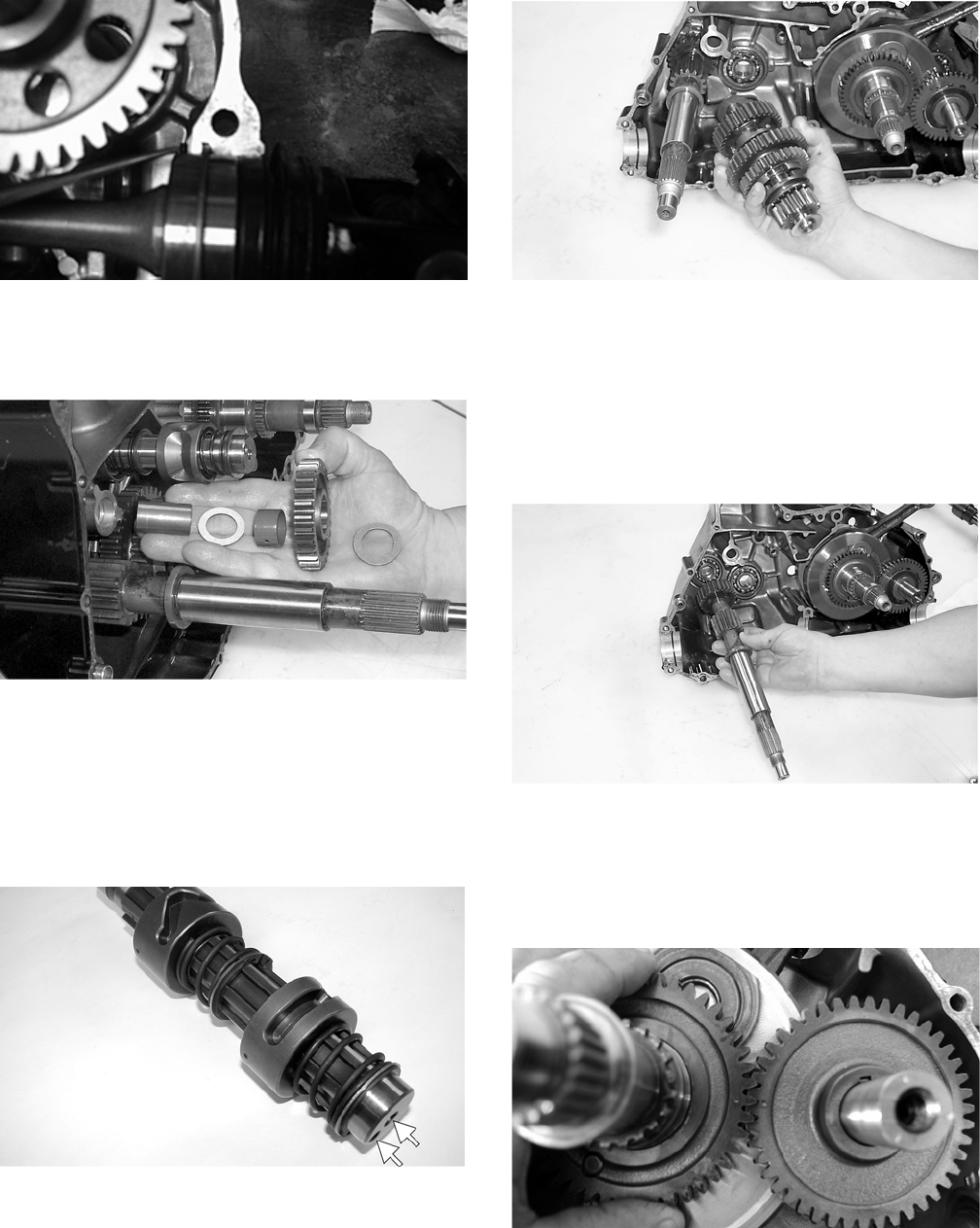
3-146
CD267
2. Remove the reverse idler gear assembly (F).
Account for all washers, shaft, bushing, and the
gear.
CC668
3. Remove the shift shaft (H); then remove the two
forks taking note of the direction of the tabs on
the forks for assembling purposes.
4. Remove the gear shift shaft (G) noting the loca-
tion of the two holes on the end of the shaft.
Account for two washers.
PR380A
5. Remove the countershaft assembly (D). Account
for a washer on each end of the countershaft.
CC674
NOTE: Do not disassemble the countershaft
assembly unless necessary. If necessary, see Ser-
vicing Center Crankcase Components sub-sec-
tion.
6. Using a rubber mallet, tap on the crankcase to
remove the driveshaft.
CC675
7. Note the timing marks on the crank balancer
assembly (B) gear and crankshaft (C) gear for
assembling purposes; then slide the crank bal-
ancer gear off the crank balancer. Account for
the key in the keyway.
CD826
8. Remove the crank balancer.
NOTE: There is a flat spot on the crank balancer
bearing flange to allow clearance past the crank-
shaft.
FOR ARCTIC CAT ATV DISCOUNT PARTS CALL 606-678-9623 OR 606-561-4983
www.mymowerparts.com
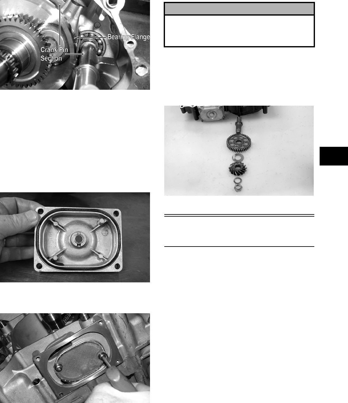
3-147
3
CD832B
9. Remove the snap ring securing the water pump
driven gear shaft.
10. Using a hydraulic press, remove the crankshaft
assembly.
NOTE: Use a protective end cap to prevent dam-
age to the crankshaft threads.
11. Remove the cap screws securing the oil strainer
cap; then remove the cap. Account for the cap
O-ring.
PR407
12. Remove the two cap screws securing the oil
strainer; then remove the strainer.
PR406
13. To remove the assembly, remove the nut secur-
ing the secondary drive gear and secondary
driven gear; then from the inside of the crank-
case using a rubber mallet, remove the output
shaft assembly. Account for the output shaft,
two gears, a shim, a washer, and the nut.
CC686
Table of Contents
(Servicing Components)
NOTE: Critical engine/transmission specifica-
tions are located at the beginning of this section.
Servicing Top-Side Components .………………….. 3-148
Valve Assembly ….…………….………….………….. 3-148
Piston Assembly ……………….…………….……….. 3-150
Cylinder/Cylinder Head Assembly………….……. 3-152
Servicing Left-Side Components ….…………….…. 3-156
Recoil Starter ….………….…………….…………….. 3-156
Servicing Right-Side Components ….…………….. 3-159
Inspecting Centrifugal Clutch Shoe ……….……. 3-159
Inspecting Clutch Housing …………….………….. 3-159
Inspecting Primary One-Way Drive ……….……. 3-159
Inspecting Oil Pump …….…………….…………….. 3-159
Driven Pulley Assembly ..……………….………….. 3-159
Servicing Center Crankcase Components ……… 3-163
Secondary Gears ………..…………….…………….. 3-163
Crankshaft Assembly …..…………….…………….. 3-164
Countershaft ………..……………..…………….……. 3-166
! CAUTION
Do not remove the remaining output shaft assembly
unless absolutely necessary. If the shaft is removed,
the shaft nut must be replaced with a new one and
the shaft must be re-shimmed.
FOR ARCTIC CAT ATV DISCOUNT PARTS CALL 606-678-9623 OR 606-561-4983
www.mymowerparts.com
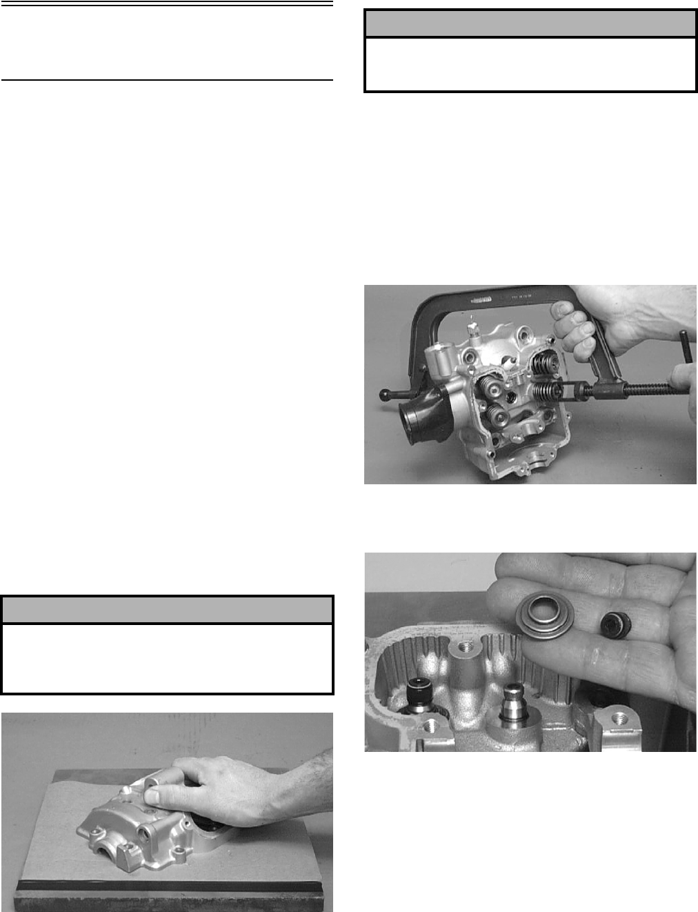
3-148
Servicing Top-Side
Components
NOTE: Whenever a part is worn excessively,
cracked, or damaged in any way, replacement is
necessary.
VALVE ASSEMBLY
When servicing valve assembly, inspect valve seats,
valve stems, valve faces, and valve stem ends for
pits, burn marks, or other signs of abnormal wear.
NOTE: Whenever a valve is out of tolerance, it
must be replaced.
Cleaning/Inspecting Valve Cover
NOTE: If the valve cover cannot be trued, the cyl-
inder head assembly must be replaced.
1. Wash the valve cover in parts-cleaning solvent.
2. Place the valve cover on the Surface Plate (p/n
0644-016) covered with #400 grit wet-or-dry
sandpaper. Using light pressure, move the valve
cover in a figure eight motion. Inspect the seal-
ing surface for any indication of high spots. A
high spot can be noted by a bright metallic fin-
ish. Correct any high spots before assembly by
continuing to move the valve cover in a figure
eight motion until a uniform bright metallic fin-
ish is attained.
CC130D
Removing Valves
NOTE: Keep all valves and valve components as
a set. Note the original location of each valve set
for use during installation. Return each valve set to
its original location during installation.
1. Using a valve spring compressor, compress the
valve springs and remove the valve cotters.
Account for an upper spring retainer.
CC132D
2. Remove the valve seal and the lower remaining
spring seat. Discard the valve seal.
CC136D
NOTE: The valve seals must be replaced.
3. Remove the valve springs; then invert the cylin-
der head and remove the valves.
Measuring Valve Stem Runout
1. Support each valve stem end with the V Blocks
(p/n 0644-022); then check the valve stem
runout using a dial indicator.
! CAUTION
Do not remove an excessive amount of the sealing
surface or damage to the camshaft will result.
Always check camshaft clearance when resurfacing
the valve cover.
! CAUTION
Water or parts-cleaning solvent must be used in
conjunction with the wet-or-dry sandpaper or dam-
age to the sealing surface may result.
FOR ARCTIC CAT ATV DISCOUNT PARTS CALL 606-678-9623 OR 606-561-4983
www.mymowerparts.com
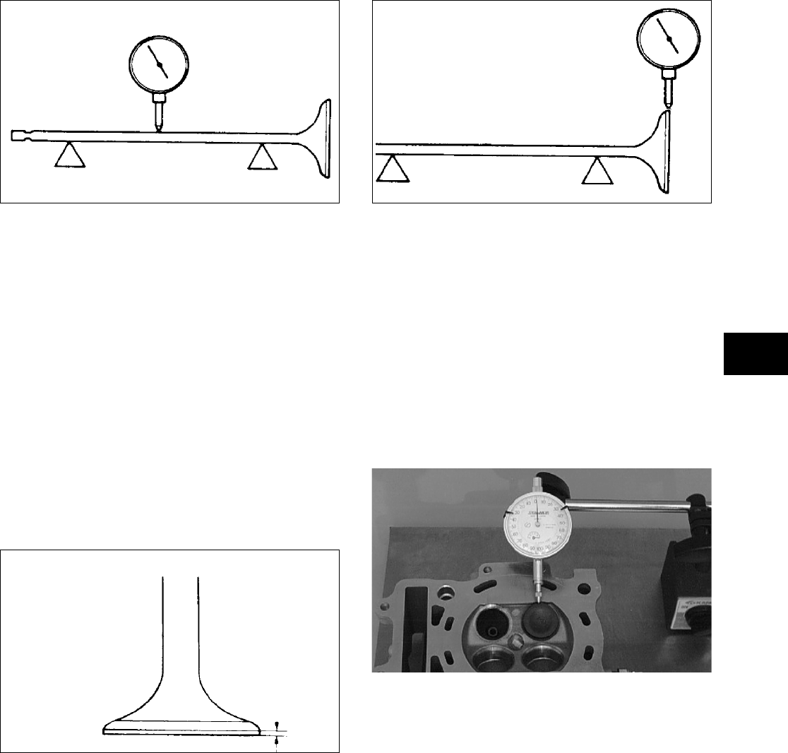
3-149
3
ATV-1082
2. Maximum runout must not exceed specifica-
tions.
Measuring Valve Stem
Outside Diameter
1. Using a micrometer, measure the valve stem
outside diameter.
2. Acceptable diameter range (intake valve) must
be within specifications.
3. Acceptable diameter range (exhaust valve) must
be within specifications.
Measuring Valve Face/Seat Width
1. Using a micrometer, measure the width of the
valve face.
ATV-1004
2. Acceptable width range must be within specifi-
cations.
Measuring Valve Face Radial
Runout
1. Mount a dial indicator on the surface plate; then
place the valve stem on a set of V blocks.
2. Position the dial indicator contact point on the
outside edge of the valve face; then zero the
indicator.
ATV1082A
3. Rotate the valve in the V blocks.
4. Maximum runout must not exceed specifications.
Measuring Valve Guide/Valve Stem
Deflection (Wobble Method)
1. Mount a dial indicator and base on the surface
plate; then place the cylinder head on the surface
plate.
2. Install the valve into the cylinder head; then posi-
tion the dial indicator contact point against the
outside edge of the valve face. Zero the indicator.
CC131D
3. Push the valve from side to side; then from top
to bottom.
4. Maximum “wobble” deflection must not exceed
specifications.
Measuring Valve Guide
(Inside Diameter)
1. Insert a snap gauge 1/2 way down into each
valve guide bore; then remove the gauge and
measure it with a micrometer.
2. Acceptable inside diameter range must be
within specifications.
3. If a valve guide is out of tolerance, it must be
replaced.
FOR ARCTIC CAT ATV DISCOUNT PARTS CALL 606-678-9623 OR 606-561-4983
www.mymowerparts.com
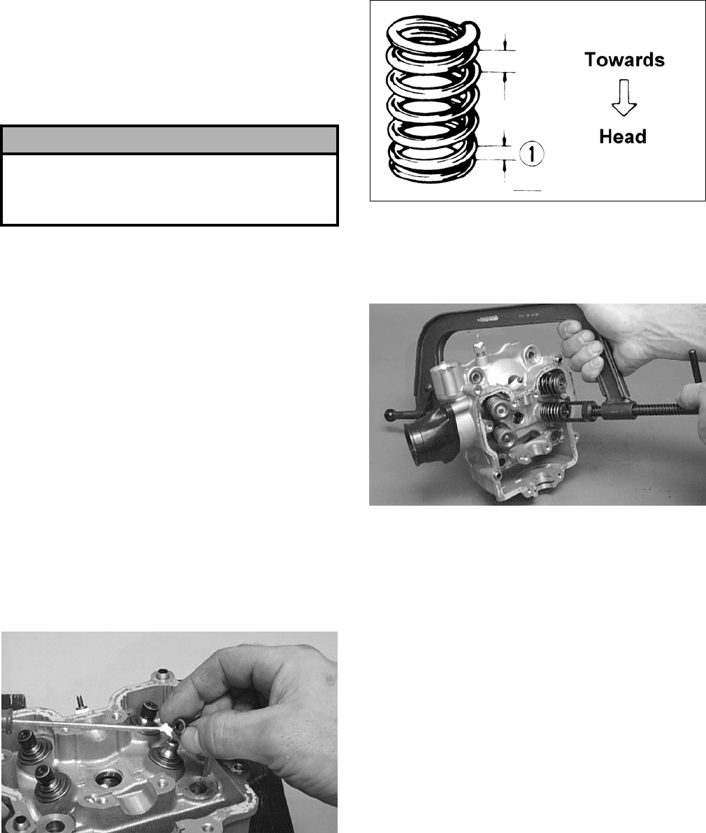
3-150
Servicing Valves/Valve
Guides/Valve Seats
If valves, valve guides, or valve seats require servic-
ing or replacement, Arctic Cat recommends that the
components be taken to a qualified machine shop
for servicing.
Measuring Rocker Arm
(Inside Diameter)
1. Using a dial calipers, measure the inside diame-
ter of the rocker arm.
2. Acceptable inside diameter range must be
within specifications.
Measuring Rocker Arm Shaft
(Outside Diameter)
1. Using a micrometer, measure the outside diame-
ter of the rocker arm shaft.
2. Acceptable outside diameter range must be
within specifications.
Installing Valves
1. Apply grease to the inside surface of the valve
seals; then place a lower spring seat and valve
guide seal over each valve guide.
CC144D
2. Insert each valve into its original location.
3. Install the valve springs with the painted end of
the spring facing away from the cylinder head.
NOTE: If the paint is not visible, install the ends
of the springs with the closest wound coils toward
the head.
ATV-1011A
4. Place a spring retainer over the valve springs;
then using the valve spring compressor, com-
press the valve springs and install the valve cot-
ters.
CC132D
PISTON ASSEMBLY
NOTE: Whenever a piston, rings, or pin are out
of tolerance, they must be replaced.
Cleaning/Inspecting Piston
1. Using a non-metallic carbon removal tool,
remove any carbon buildup from the dome of
the piston.
2. Inspect the piston for cracks in the piston pin,
dome, and skirt areas.
3. Inspect the piston for seizure marks or scuffing.
Repair with #400 grit wet-or-dry sandpaper and
water or honing oil.
NOTE: If scuffing or seizure marks are too deep
to correct with the sandpaper, replace the piston.
4. Inspect the perimeter of each piston for signs of
excessive “blowby.” Excessive “blowby” indi-
cates worn piston rings or an out-of-round cylin-
der.
! CAUTION
If valves are discolored or pitted or if the seating
surface is worn, the valve must be replaced. Do not
attempt to grind the valves or severe engine damage
may occur.
FOR ARCTIC CAT ATV DISCOUNT PARTS CALL 606-678-9623 OR 606-561-4983
www.mymowerparts.com
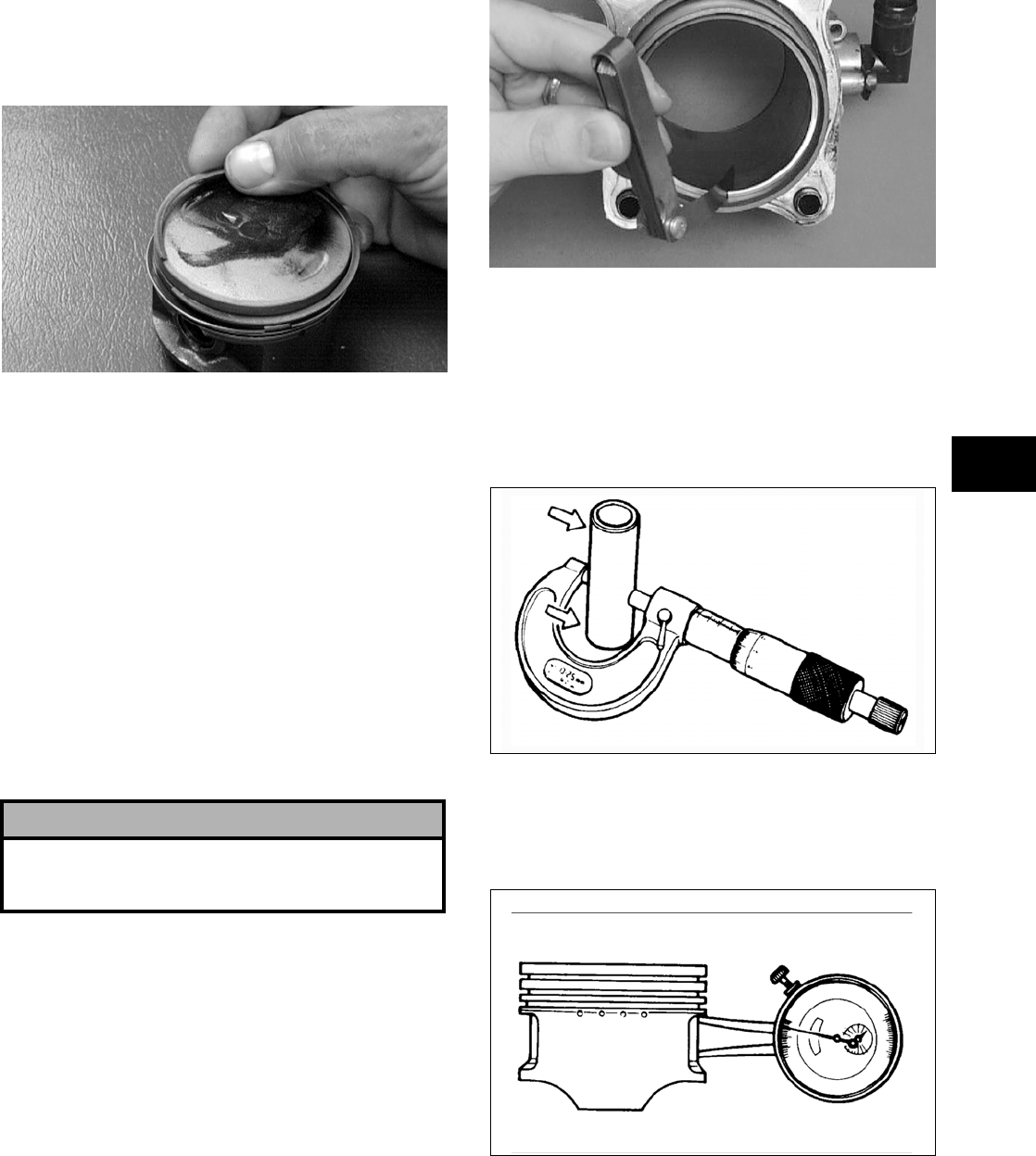
3-151
3
Removing Piston Rings
1. Starting with the top ring, slide one end of the
ring out of the ring-groove.
CC400D
2. Remove each ring by working it toward the
dome of the piston while rotating it out of the
groove.
NOTE: If the existing rings will not be replaced
with new ones, note the location of each ring for
proper installation. When installing new rings,
install as a complete set only.
Cleaning/Inspecting Piston Rings
1. Take an old piston ring and snap it into two
pieces; then grind the end of the old ring to a 45°
angle and to a sharp edge.
2. Using the sharpened ring as a tool, clean carbon
from the ring-grooves. Be sure to position the
ring with its tapered side up.
Measuring Piston-Ring End Gap
(Installed)
1. Place each compression ring in the wear portion
of the cylinder. Use the piston to position each
ring squarely in the cylinder.
2. Using a feeler gauge, measure each piston-ring
end gap. Acceptable ring end gap must be
within specifications.
CC280D
Measuring Piston Pin (Outside
Diameter) and Piston-Pin Bore
1. Measure the piston pin outside diameter at each
end and in the center. If measurement is not
within specifications, the piston pin must be
replaced.
ATV-1070
2. Insert an inside dial indicator into the piston-pin
bore. The diameter must not exceed specifica-
tions. Take two measurements to ensure accu-
racy.
ATV-1069
Measuring Piston Skirt/
Cylinder Clearance
1. Measure the cylinder front to back in six places.
! CAUTION
Improper cleaning of the ring-grooves by the use of
the wrong type of ring-groove cleaner will result in
severe damage to the piston.
FOR ARCTIC CAT ATV DISCOUNT PARTS CALL 606-678-9623 OR 606-561-4983
www.mymowerparts.com
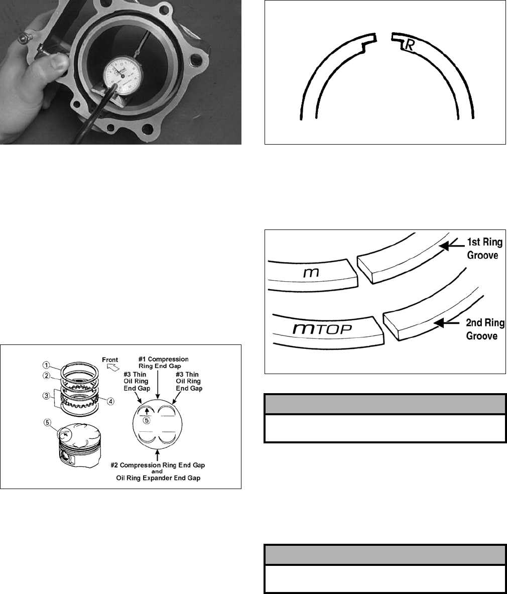
3-152
CC127D
2. Measure the corresponding piston diameter at a
point 15 mm (0.6 in.) above the piston skirt at a
right angle to the piston-pin bore. Subtract this
measurement from the measurement in step 1.
The difference (clearance) must be within speci-
fications.
Installing Piston Rings
1. Install ring expander (4) in the bottom groove of
the piston; then install the thin oil rings (3) over
the expander making sure the expander ends do
not overlap. Stagger the end gaps of the upper
and lower thin oil rings according to the illustra-
tion.
ATV-1085B
NOTE: Note the direction of the exhaust side of
the piston (5) for correct ring end gap orientation.
2. On the 500, install the compression rings (1 and
2) so the letter on the top surface of each ring
faces the dome of the piston. Rotate the rings
until the ring end gaps are on directly opposite
sides of the piston (see illustration).
NOTE: The chrome (silver) ring should be
installed in the top position.
726-306A
3. On the 650 H1, the ring with the orientation
mark (MTOP) should be installed in the second
(middle) groove and the ring with the orienta-
tion mark (M) should be installed in the first
(top) groove.
ATV-1024A
CYLINDER/CYLINDER HEAD
ASSEMBLY
NOTE: If the cylinder/cylinder head assembly
cannot be trued, they must be replaced.
Cleaning/Inspecting Cylinder Head
1. Using a non-metallic carbon removal tool,
remove any carbon buildup from the combus-
tion chamber being careful not to nick, scrape,
or damage the combustion chamber or the seal-
ing surface.
2. Inspect the spark plug hole for any damaged
threads. Repair damaged threads using a
“heli-coil” insert.
! CAUTION
Incorrect installation of the piston rings will result in
engine damage.
! CAUTION
The cylinder head studs must be removed for this
procedure.
FOR ARCTIC CAT ATV DISCOUNT PARTS CALL 606-678-9623 OR 606-561-4983
www.mymowerparts.com
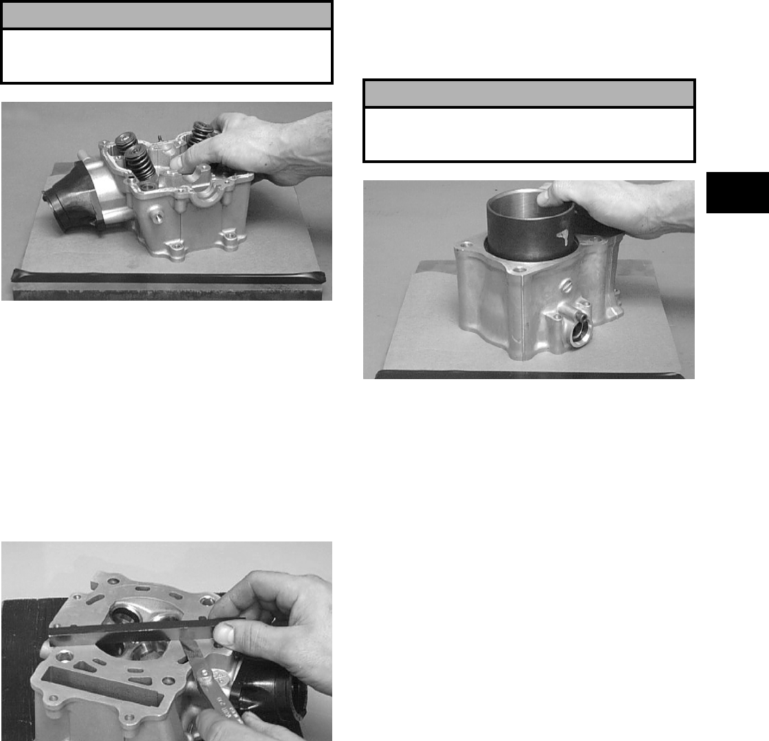
3-153
3
3. Place the cylinder head on the surface plate cov-
ered with #400 grit wet-or-dry sandpaper. Using
light pressure, move the cylinder head in a fig-
ure eight motion. Inspect the sealing surface for
any indication of high spots. A high spot can be
noted by a bright metallic finish. Correct any
high spots before assembly by continuing to
move the cylinder head in a figure eight motion
until a uniform bright metallic finish is attained.
CC128D
Measuring Cylinder Head
Distortion
1. Remove any carbon buildup in the combustion
chamber.
2. Lay a straightedge across the cylinder head; then
using a feeler gauge, check the distortion factor
between the head and the straightedge.
3. Maximum distortion must not exceed specifica-
tions.
CC141D
Cleaning/Inspecting Cylinder
1. Wash the cylinder in parts-cleaning solvent.
2. Inspect the cylinder for pitting, scoring, scuff-
ing, warpage, and corrosion. If marks are found,
repair the surface using a cylinder hone (see
Honing Cylinder in this sub-section).
3. Place the cylinder on the surface plate covered
with #400 grit wet-or-dry sandpaper. Using light
pressure, move the cylinder in a figure eight
motion. Inspect the sealing surface for any indi-
cation of high spots. A high spot can be noted by
a bright metallic finish. Correct any high spots
before assembly by continuing to move the cyl-
inder in a figure eight motion until a uniform
bright metallic finish is attained.
CC129D
Inspecting Cam Chain Guide
1. Inspect cam chain guide for cuts, tears, breaks,
or chips.
2. If the chain guide is damaged, it must be
replaced.
Honing Cylinder
1. Using a slide gauge and a dial indicator or a
snap gauge, measure the cylinder bore diameter
in three locations from top to bottom and again
from top to bottom at 90° from the first mea-
surements for a total of six measurements. The
trueness (out-of-roundness) is the difference
between the highest and lowest reading. Maxi-
mum trueness (out-of-roundness) must not
exceed specifications.
! CAUTION
Water or parts-cleaning solvent must be used in
conjunction with the wet-or-dry sandpaper or dam-
age to the sealing surface may result.
! CAUTION
Water or parts-cleaning solvent must be used in
conjunction with the wet-or-dry sandpaper or dam-
age to the sealing surface may result.
FOR ARCTIC CAT ATV DISCOUNT PARTS CALL 606-678-9623 OR 606-561-4983
www.mymowerparts.com
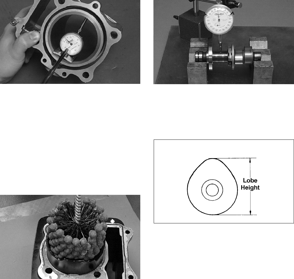
3-154
CC127D
2. Wash the cylinder in parts-cleaning solvent.
3. Inspect the cylinder for pitting, scoring, scuff-
ing, and corrosion. If marks are found, repair the
surface using a ball hone.
NOTE: To produce the proper 60° cross-hatch
pattern, use a low RPM drill (600 RPM) at the rate
of 30 strokes per minute. If honing oil is not avail-
able, use a lightweight petroleum-based oil. Thor-
oughly clean cylinder after honing using soap and
hot water. Dry with compressed air; then immedi-
ately apply oil to the cylinder bore. If the bore is
severely damaged or gouged, replace the cylinder.
CC390D
4. If any measurement exceeds the limit, replace
the cylinder and piston.
Measuring Camshaft Runout
NOTE: If the camshaft is out of tolerance, it must
be replaced.
1. Place the camshaft on a set of V blocks; then
position the dial indicator contact point against
the shaft and zero the indicator.
CC283D
2. Rotate the camshaft and note runout; maximum
tolerance must not exceed specifications.
Measuring Camshaft Lobe Height
1. Using a calipers, measure each cam lobe height.
ATV1013A
2. The lobe heights must not exceed minimum
specifications.
Inspecting Camshaft Bearing
Journal
1. Inspect the bearing journal for scoring, seizure
marks, or pitting.
2. If excessive scoring, seizure marks, or pitting is
found, the cylinder head assembly must be
replaced.
Measuring Camshaft to
Cylinder Head Clearance
1. Remove the adjuster screws and jam nuts.
FOR ARCTIC CAT ATV DISCOUNT PARTS CALL 606-678-9623 OR 606-561-4983
www.mymowerparts.com
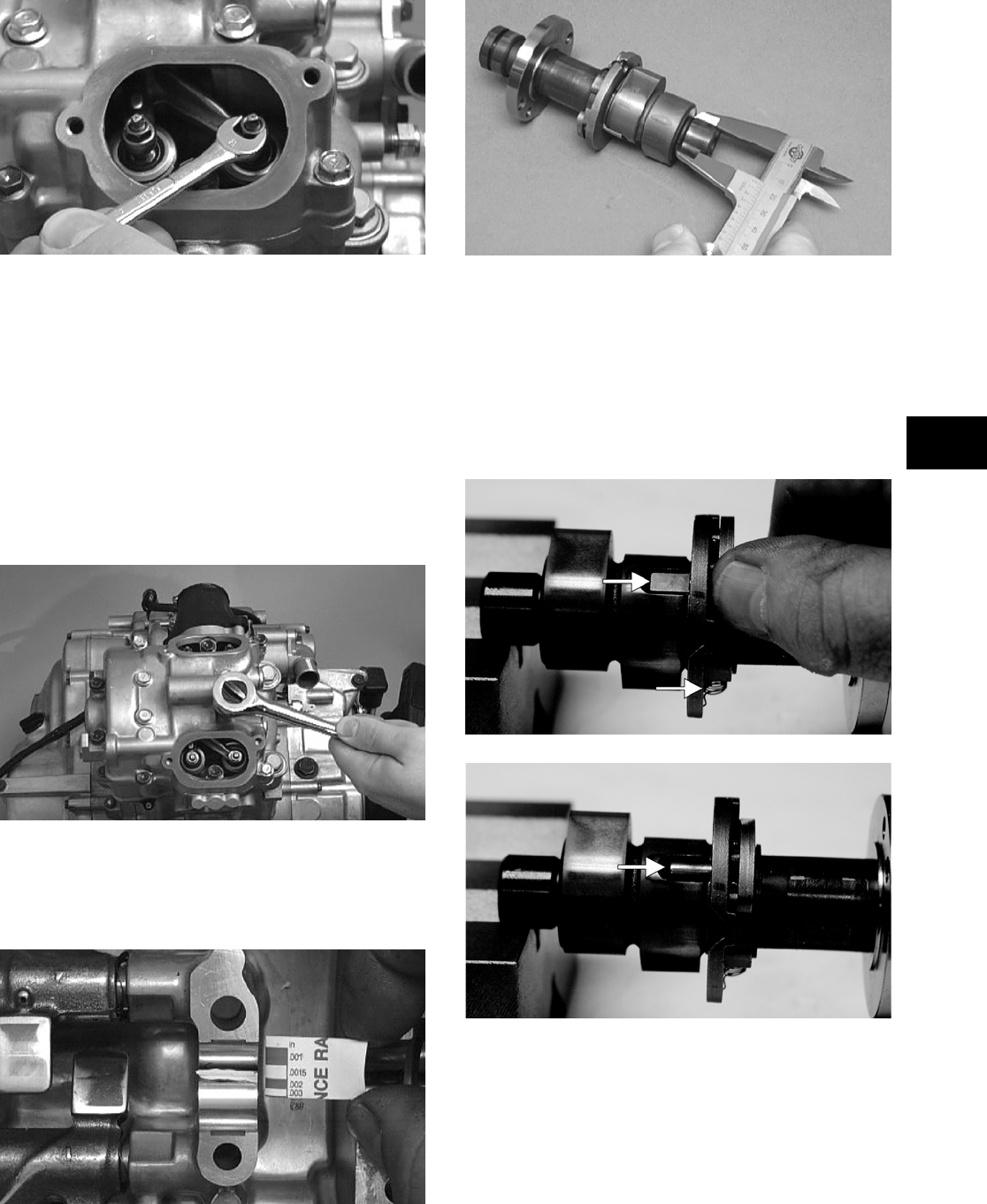
3-155
3
CC005D
2. Place a strip of plasti-gauge in each of the cam-
shaft lands in the cylinder head.
3. Place the valve cover on the cylinder head and
secure with the valve cover cap screws. Tighten
securely.
NOTE: Do not rotate the camshaft when measur-
ing clearance.
4. Remove the cap screws securing the valve cover
to the cylinder; then remove the valve cover and
camshaft.
CC003D
5. Match the width of the plasti-gauge with the
chart found on the plasti-gauge packaging to
determine camshaft to cylinder head and valve
cover clearance.
CC145D
6. If clearance is excessive, measure the journals of
the camshaft.
CC287D
NOTE: If the journals are worn, replace the cam-
shaft; then measure the clearance again. If it is still
out of tolerance, replace the cylinder head.
Inspecting Camshaft Spring/Drive
Pin
1. Inspect the spring and drive pin for damage.
CF061A
CF060A
2. If damaged, the camshaft must be replaced.
FOR ARCTIC CAT ATV DISCOUNT PARTS CALL 606-678-9623 OR 606-561-4983
www.mymowerparts.com
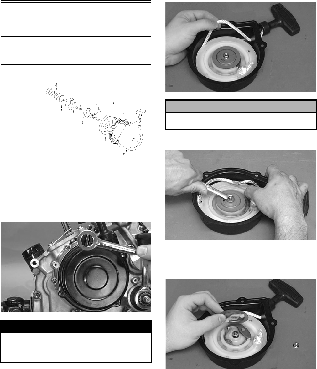
3-156
Servicing Left-Side
Components
RECOIL STARTER
0737-764
Removing/Disassembling
1. Remove the cap screws securing the recoil
starter assembly to the left-side cover; then
remove the starter.
CC039D
2. Rotate the reel counterclockwise until the notch
of the reel is near the rope guide in the case.
Guide the rope into the notch and slowly allow
the reel to retract until all spiral spring tension is
released.
B600D
3. Remove the nut.
B601D
4. Slowly release the friction plate and lift the plate
with ratchet guide free of the recoil case; then
remove the ratchet guide from the friction plate.
B602D
5. Remove the spring, collar, and friction spring.
! WARNING
During the disassembly procedure, continuous
downward pressure must be exerted on the reel
so it does not accidentally disengage and cause
injury.
KEY
1. Recoil Starter Assy
2. Rope Assy
3. Spiral Spring
4. Reel
5. Ratchet Assy
6. Nut
7. Cap Screw
8. Nut
9. Starter Cup
10. O-Ring
11. O-Ring
12. Spacer
13. Oil Seal
14. Bearing
! CAUTION
During the disassembly procedure, make sure all
spring tension is released before continuing.
FOR ARCTIC CAT ATV DISCOUNT PARTS CALL 606-678-9623 OR 606-561-4983
www.mymowerparts.com
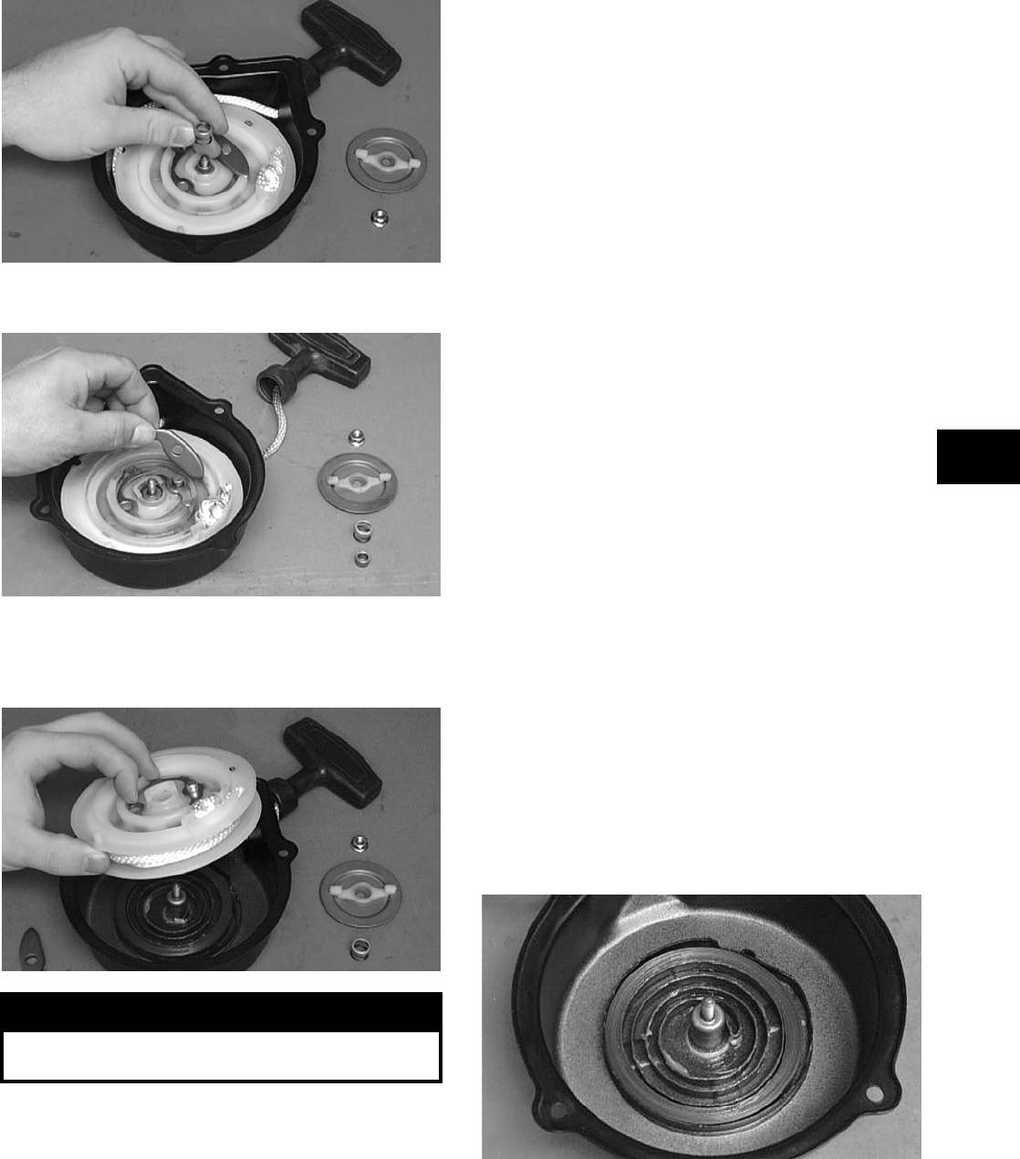
3-157
3
B603D
6. Remove the ratchet and account for the pin.
B604D
7. Carefully lift the reel from the case making sure
the spiral spring does not accidentally disengage
from the case.
B605D
8. Remove the protective cover from the starter
handle and pull the rope out of the handle; then
untie the knot in the rope and remove the han-
dle.
NOTE: Do not remove the spiral spring unless
replacement is necessary. It should be visually
inspected in place to save time. If replacement is
necessary, follow steps 9-10.
9. Remove the spring from the case by lifting the
spring end up and out. Hold the remainder of the
spring with thumbs and alternately release each
thumb to allow the spring to gradually release
from the case.
10. Unwind the rope from the reel and remove the
rope.
Cleaning and Inspecting
NOTE: Whenever a part is worn excessively,
cracked, or damaged in any way, replacement is
necessary.
1. Clean all components.
2. Inspect the springs and ratchet for wear or dam-
age.
3. Inspect the reel and case for cracks or damage.
4. Inspect the shaft for wear, cracks, or damage.
5. Inspect the rope for breaks or fraying.
6. Inspect the spiral spring for cracks, crystalliza-
tion, or abnormal bends.
7. Inspect the handle for damage, cracks, or deteri-
oration.
Assembling/Installing
1. If removed, insert the spiral spring into the case
with the outer end of the spring around the
mounting lug in the case; then wind it in a coun-
terclockwise direction until the complete spring
is installed.
NOTE: The spiral spring must seat evenly in the
recoil case.
B606D
2. Insert the rope through the hole in the reel and
tie a knot in the end; then wrap the rope counter-
clockwise around the reel leaving approximately
50 cm (20 in.) of rope free of the reel.
! WARNING
Care must be taken when lifting the reel free of
the case. Wear safety glasses to avoid injury.
FOR ARCTIC CAT ATV DISCOUNT PARTS CALL 606-678-9623 OR 606-561-4983
www.mymowerparts.com
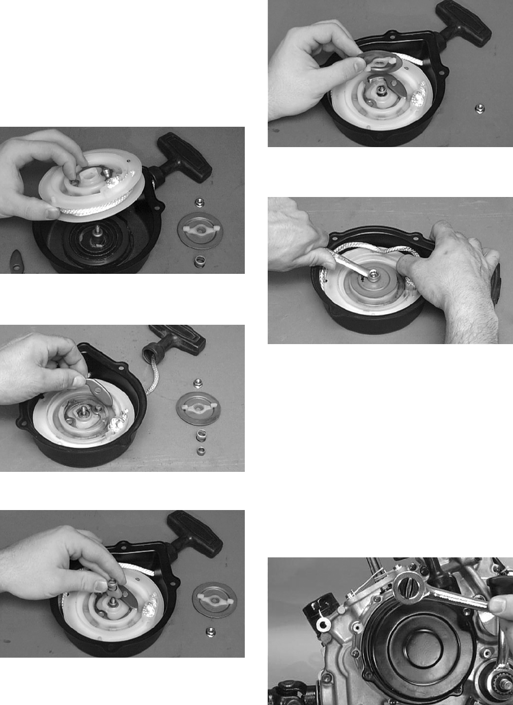
3-158
3. Apply low-temperature grease to the spring and
hub.
4. Thread the end of the rope through the guide
hole of the case; then thread the rope through the
handle and secure it with a double knot. Install
the protective cover into the handle.
5. Align the inner hook of the spiral spring with the
notch in the reel.
B605D
6. Install the ratchet making sure the end is prop-
erly installed on the reel.
B604D
7. Install the friction spring and the spring cover.
B603D
8. Install the friction plate with the ratchet guide
fitting into the ratchet.
B602D
9. While pushing down on the reel, install the nut.
Tighten securely.
B601D
10. With the 50 cm (20 in.) of rope exposed, hook
the rope in the notch of the reel.
11. Rotate the reel four turns counterclockwise; then
release the rope from the notch and allow the
rope to retract.
12. Pull the rope out two or three times to check for
correct tension.
NOTE: Increasing the rotations in step 11 will
increase spring tension.
13. Place the recoil starter assembly into position on
the left-side cover; then tighten the cap screws
to specifications.
CC039D
FOR ARCTIC CAT ATV DISCOUNT PARTS CALL 606-678-9623 OR 606-561-4983
www.mymowerparts.com
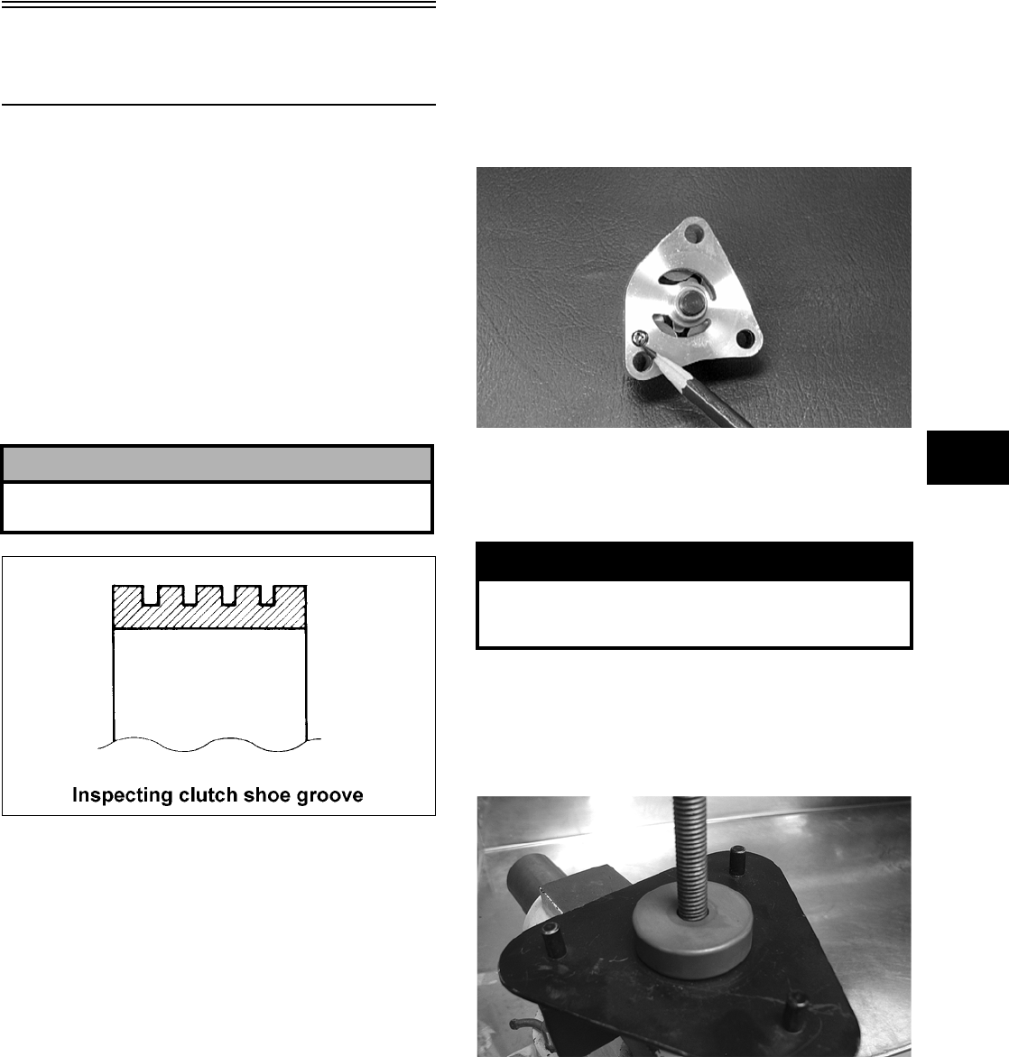
3-159
3
Servicing Right-Side
Components
NOTE: Whenever a part is worn excessively,
cracked, damaged in any way, or out of tolerance,
replacement is necessary.
INSPECTING CENTRIFUGAL
CLUTCH SHOE
1. Inspect the clutch shoes for uneven wear, chips,
cracks, or discoloration. If any shoe is damaged,
replace the complete set.
2. Inspect the clutch shoes for wear or damage. If
any shoe is worn to the bottom of the groove,
replace the complete set.
ATV1014
INSPECTING CLUTCH HOUSING
1. Inspect the clutch housing for burns, grooving,
cracks, or uneven wear.
2. If the housing is damaged in any way, the hous-
ing must be replaced.
INSPECTING PRIMARY
ONE-WAY DRIVE
1. Insert the drive into the clutch housing.
2. Rotate the inner race by hand and verify the
inner race rotates only one direction.
3. If the inner race is locked in place or rotates both
directions, the drive assembly must be replaced.
INSPECTING OIL PUMP
1. Inspect the pump for damage.
2. It is inadvisable to remove the screw securing
the pump halves. If the oil pump is damaged, it
must be replaced.
CC446D
DRIVEN PULLEY ASSEMBLY
Disassembling
1. Secure Driven Pulley Compressor (p/n
0444-121) in a suitable holding fixture such as a
bench vise; then remove the wing nut, holding
handle, flat washer, and pilot bushing leaving
the large spacer on the compressor tool base.
CD047
2. Place the driven pulley assembly onto the com-
pressor tool base engaging the dowel pins into
appropriate holes in the fixed face of the assem-
bly.
! CAUTION
Always replace the clutch shoes as a complete set
or severe imbalance could occur.
! WARNING
This procedure involves relaxing a compressed
spring assembly. DO NOT attempt disassembling
without the proper tools.
FOR ARCTIC CAT ATV DISCOUNT PARTS CALL 606-678-9623 OR 606-561-4983
www.mymowerparts.com
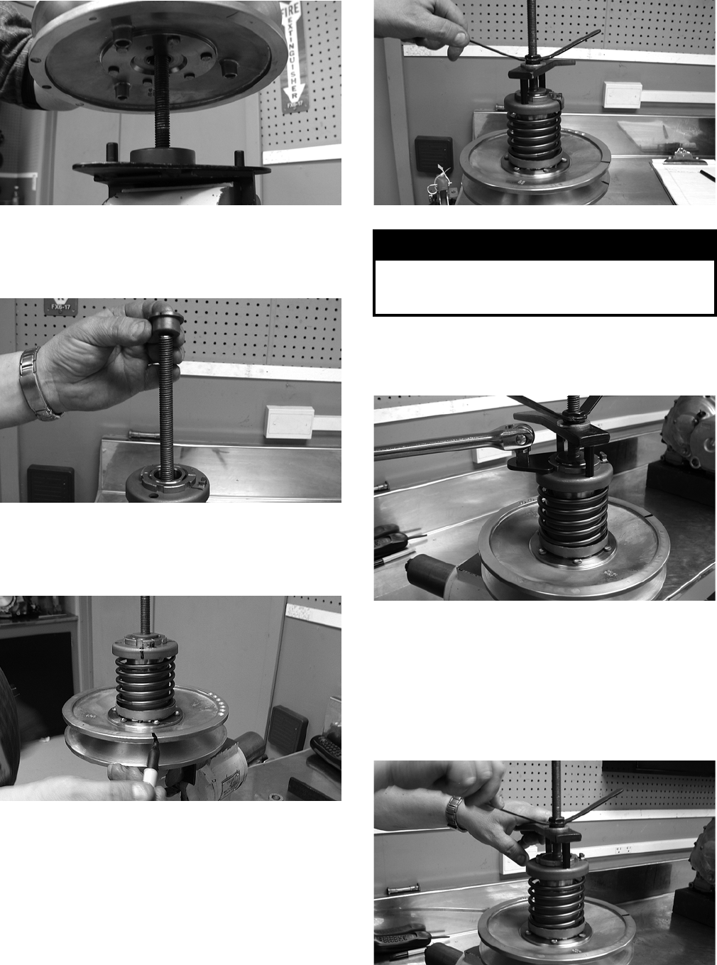
3-160
CD048
3. Install the pilot bushing with the machined end
directed down; then fit the bushing into the pul-
ley hub.
CD067
4. Using a suitable marking pen, make alignment
marks on the fixed face spring holder and both
pulley faces.
CD049
5. Place the holding handle on the spring holder
fitting the two dowel pins into the spring holder
face; then install a flat washer and the wing nut.
Turn the wing nut down until resistance is felt.
NOTE: Do not use the wing nut to compress the
spring further.
CD050
6. Using a spanner and suitable breaker bar, loosen
the notched-ring nut; then spin the nut free of
the hub.
CD051
7. Firmly hold the handle and slowly turn the wing
nut counterclockwise to relax the spring.
NOTE: There will be a tendency for the handle to
rotate clockwise approximately ¼ turn as the
spring holder clears the flats or hub. This is due to
a slight counterclockwise preload on the spring.
CD052
! WARNING
The spring assembly is under pressure. Extreme
care must be taken when relaxing the spring. Always
wear safety glasses. Use proper tools only.
FOR ARCTIC CAT ATV DISCOUNT PARTS CALL 606-678-9623 OR 606-561-4983
www.mymowerparts.com
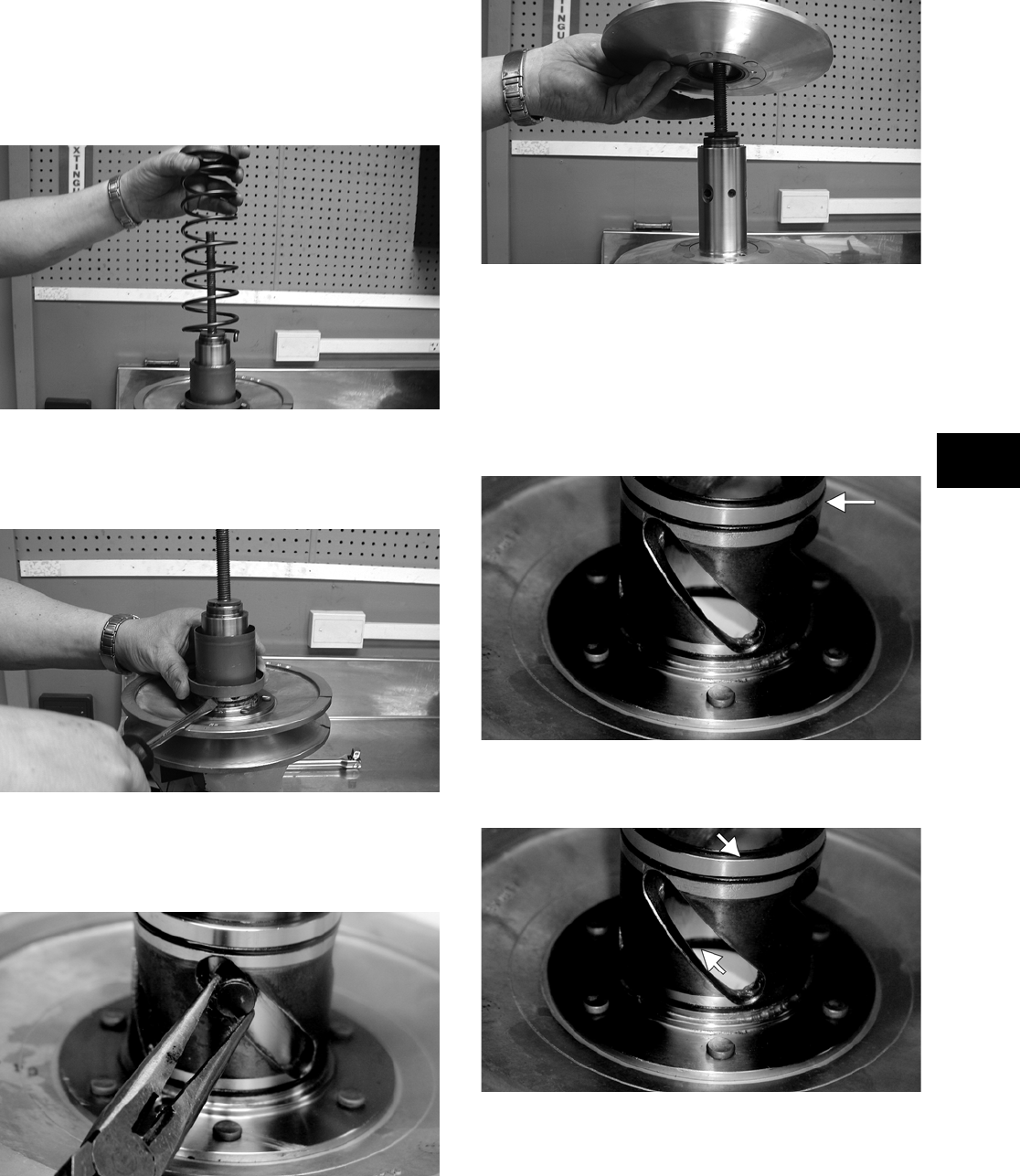
3-161
3
8. Release the preload slowly; then continue to
relax the spring until the wing nut is flush with
the end of the threads.
9. Firmly holding the spring and spring holder,
remove the wing nut; then remove the spring.
CD053
10. Using a thin pry-bar or screwdriver, work the
movable face sleeve upward and free of the
O-rings; then remove the sleeve.
CD054
11. Remove the four pins and spacers from the cam
slots in the movable face; then remove the mov-
able face.
CF091
CD056
Inspecting
1. Inspect the pulley faces for wear, galling, or
grooving.
2. Inspect the O-rings on the movable face for
nicks, tears, or swelling.
CF092A
3. Inspect two grease seals in the movable face for
nicks, cuts, or damage.
CF095A
4. Inspect the pins and bushings for wear, flat
spots, looseness, or cracking.
Assembling
1. Place the fixed face of the driven pulley on the
pulley compressor base making sure the dowel
pins are engaged in the appropriate holes in the
pulley face.
FOR ARCTIC CAT ATV DISCOUNT PARTS CALL 606-678-9623 OR 606-561-4983
www.mymowerparts.com
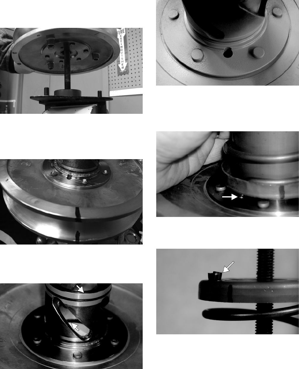
3-162
NOTE: Make sure the spacer is on the base or
damage to the fixed face will occur when the
spring is compressed.
CD048
2. Apply multi-purpose grease to the O-rings and
grease seals on the movable face; then install on
the fixed face making sure the alignment marks
are properly aligned.
CD060
3. Install the four pins and spacers into the fixed
face hub; then pack the cam slots in the movable
face with multi-purpose grease.
CF095A
4. Install the movable face sleeve aligning the hole
in the spring seat with the spring anchor hole in
the movable face.
CF097
5. Install the spring over the hub and movable face
sleeve; then insert the end of the spring through
the sleeve and into the spring anchor hole in the
movable face.
CF089A
6. Place the spring holder on the spring engaging
the spring end with the appropriate anchor hole.
CF087A
7. Assemble the notched-ring nut, spring holding
handle, one flat washer, and the wing nut in
order on the pulley compressor bolt; then thread
the wing nut onto the bolt.
FOR ARCTIC CAT ATV DISCOUNT PARTS CALL 606-678-9623 OR 606-561-4983
www.mymowerparts.com
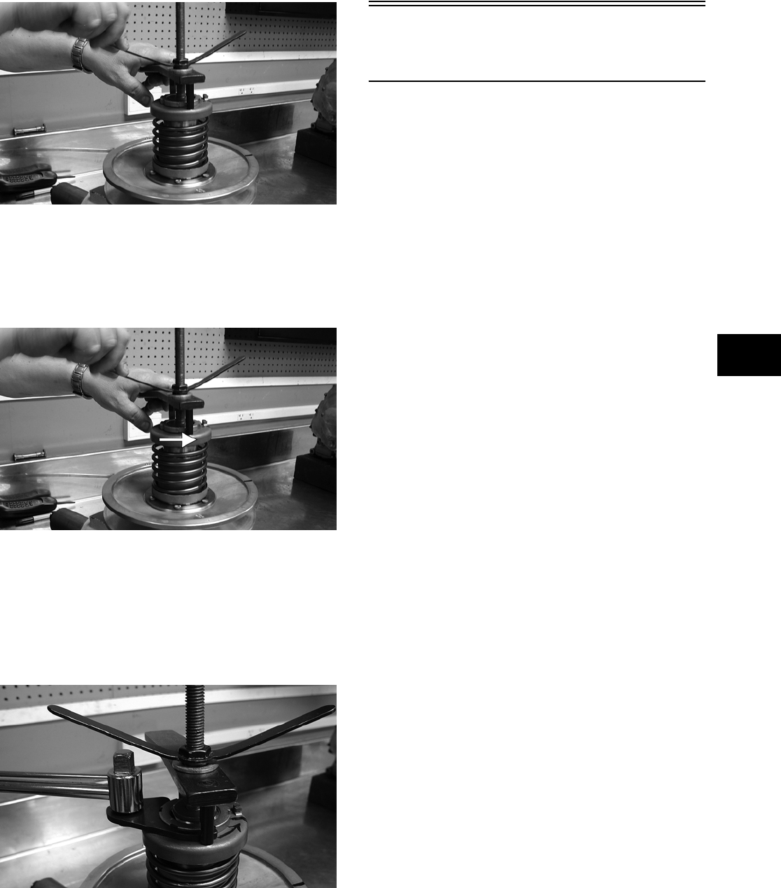
3-163
3
CD052
8. Compress the spring until the spring holder
nears the threads on the fixed face hub; then
using the handle, wind the spring holder coun-
terclockwise to align the flats of the spring
holder and hub.
CD052A
9. Continue compressing the spring while guiding
the spring holder onto the hub. When a slight
resistance is felt, stop turning the wing nut.
10. Install the nut (threads coated with red Loctite
#271); then tighten the nut to specification using
the spanner and a torque wrench.
CD066
11. Remove the wing nut, washer, and holding han-
dle; then remove the driven pulley from the pul-
ley compressor.
Servicing Center
Crankcase Components
NOTE: Whenever a part is worn excessively,
cracked, damaged in any way, or out of tolerance,
replacement is necessary.
SECONDARY GEARS
NOTE: When checking and correcting secondary
gear backlash and tooth contact, the universal
joint must be secured to the front shaft or false
measurements will occur.
Checking Backlash
NOTE: The rear shaft and bevel gear must be
removed for this procedure. Also, always start with
the original shims on the rear shaft.
1. Place the left-side crankcase cover onto the
left-side crankcase half to prevent runout of the
secondary transmission output shaft.
2. Install the secondary driven output shaft assem-
bly onto the crankcase.
3. Mount the dial indicator so the tip is contacting
a tooth on the secondary driven bevel gear.
4. While rocking the driven bevel gear back and
forth, note the maximum backlash reading on
the gauge.
5. Acceptable backlash range is 0.05-0.33 mm
(0.002-0.013 in.).
Correcting Backlash
NOTE: If backlash measurement is within the
acceptable range, no correction is necessary.
1. If backlash measurement is less than specified,
remove an existing shim, measure it, and install
a new thinner shim.
2. If backlash measurement is more than specified,
remove an existing shim, measure it, and install
a thicker shim.
NOTE: Continue to remove, measure, and install
until backlash measurement is within tolerance.
Note the following chart.
FOR ARCTIC CAT ATV DISCOUNT PARTS CALL 606-678-9623 OR 606-561-4983
www.mymowerparts.com
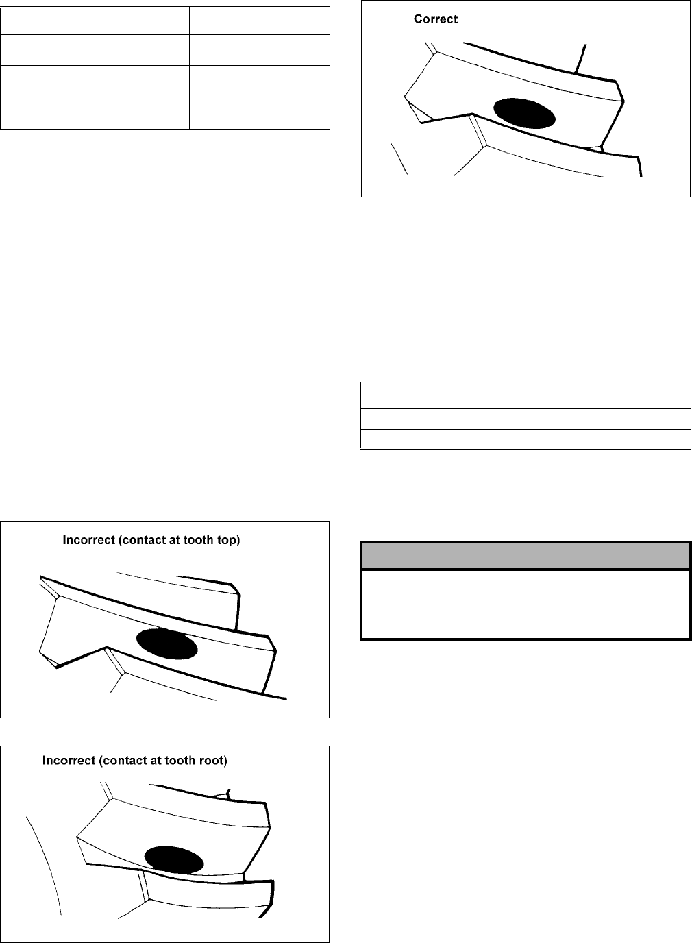
3-164
Checking Tooth Contact
NOTE: After correcting backlash of the second-
ary driven bevel gear, it is necessary to check
tooth contact.
1. Remove the secondary driven output shaft
assembly from the left-side crankcase half.
2. Clean the secondary driven bevel gear teeth of
old oil and grease residue.
3. Apply a thin, even coat of a machinist-layout
dye to several teeth of the gear.
4. Install the secondary driven output shaft assem-
bly.
5. Rotate the secondary driven bevel gear several
revolutions in both directions.
6. Examine the tooth contact pattern in the dye and
compare the pattern to the illustrations.
ATV-0103
ATV-0105
ATV-0104
Correcting Tooth Contact
NOTE: If tooth contact pattern is comparable to
the correct pattern illustration, no correction is
necessary.
If tooth contact pattern is comparable to an incorrect
pattern, correct tooth contact according to the fol-
lowing chart.
NOTE: To correct tooth contact, steps 1 and 2
(with NOTE) of “Correcting Backlash” must be fol-
lowed and the above “Tooth Contact/Shim Correc-
tion” chart must be consulted.
CRANKSHAFT ASSEMBLY
Measuring Connecting Rod
(Small End Inside Diameter)
1. Insert a snap gauge into the upper connecting
rod small end bore; then remove the gauge and
measure it with micrometer.
Backlash Measurement Shim Correction
Under 0.05 mm (0.002 in.) Decrease Shim
Thickness
At 0.05-0.33 mm
(0.002-0.013 in.)
No Correction Required
Over 0.33 mm (0.013 in.) Increase Shim
Thickness
Tooth Contact Shim Correction
Contacts at Top Decrease Shim Thickness
Contacts at Root Increase Shim Thickness
! CAUTION
After correcting tooth contact, backlash must again
be checked and corrected (if necessary). Continue
the correcting backlash/correcting tooth contact pro-
cedures until they are both within tolerance values.
FOR ARCTIC CAT ATV DISCOUNT PARTS CALL 606-678-9623 OR 606-561-4983
www.mymowerparts.com
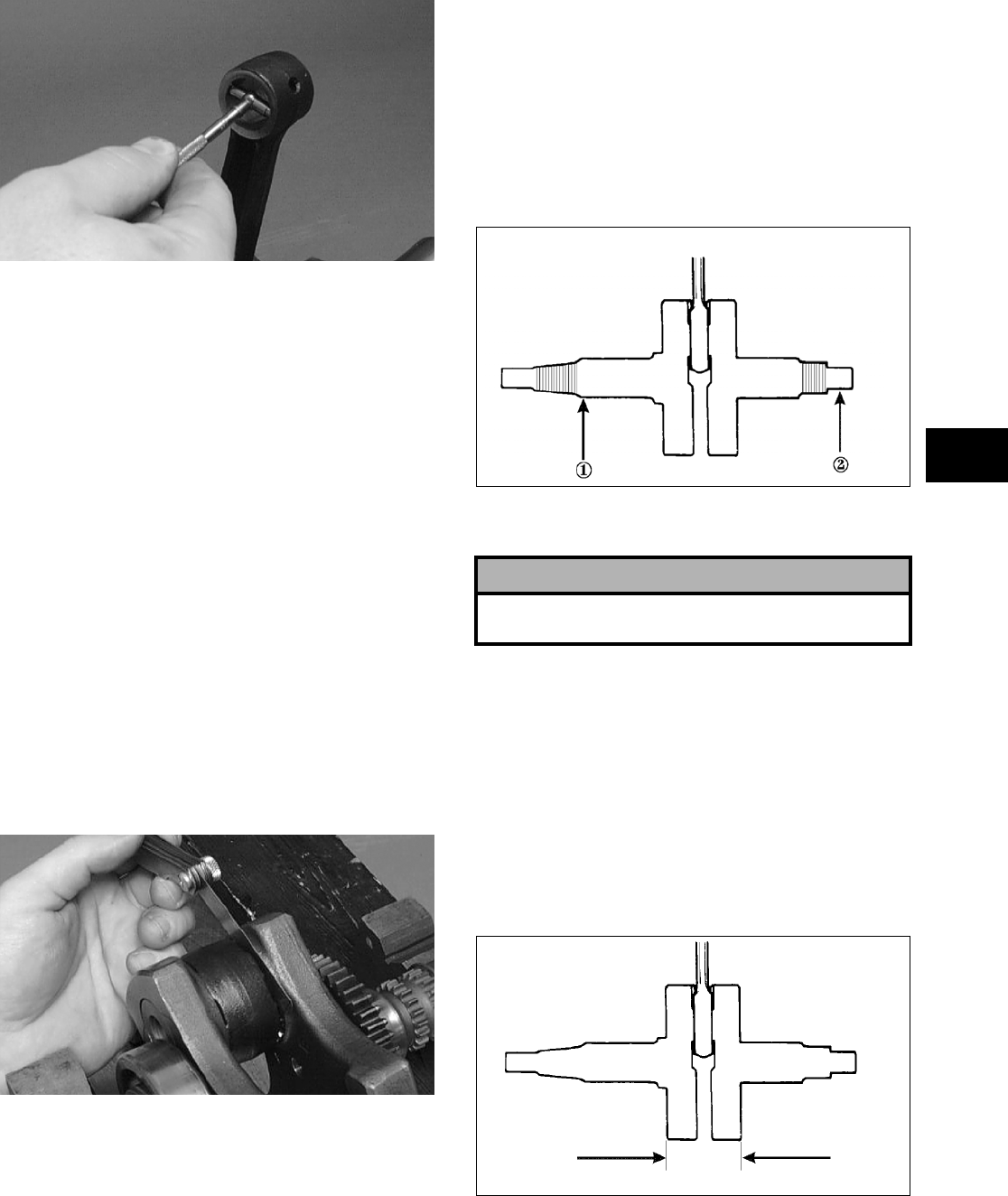
3-165
3
CC290D
2. Maximum diameter must not exceed specifications.
Measuring Connecting Rod
(Small End Deflection)
1. Place the crankshaft on a set of V-blocks and
mount a dial indicator and base on the surface
plate. Position the indicator contact point against
the center of the connecting rod small end jour-
nal.
2. Zero the indicator and push the small end of the
connecting rod away from the dial indicator.
3. Maximum deflection must not exceed specifica-
tions.
Measuring Connecting Rod
(Big End Side-to-Side)
1. Push the lower end of the connecting rod to one
side of the crankshaft journal.
2. Using a feeler gauge, measure the gap between
the connecting rod and crankshaft journal.
CC289D
3. Acceptable gap range must be within specifica-
tions.
Measuring Connecting Rod
(Big End Width)
1. Using a calipers, measure the width of the con-
necting rod at the big-end bearing.
2. Acceptable width range must be within specifi-
cations.
Measuring Crankshaft (Runout)
1. Place the crankshaft on a set of V blocks.
2. Mount a dial indicator and base on the surface
plate. Position the indicator contact at point 1 of
the crankshaft.
ATV-1074
3. Zero the indicator and rotate the crankshaft slowly.
4. Maximum runout must not exceed specifications.
NOTE: Proceed to check runout on the other end
of the crankshaft by positioning the indicator con-
tact at point 2 and following steps 2-4.
Measuring Crankshaft
(Web-to-Web)
1. Using a calipers, measure the distance from the
outside edge of one web to the outside edge of
the other web.
ATV-1017
2. Acceptable width range must be within specifi-
cations.
! CAUTION
Care should be taken to support the connecting rod
when rotating the crankshaft.
FOR ARCTIC CAT ATV DISCOUNT PARTS CALL 606-678-9623 OR 606-561-4983
www.mymowerparts.com
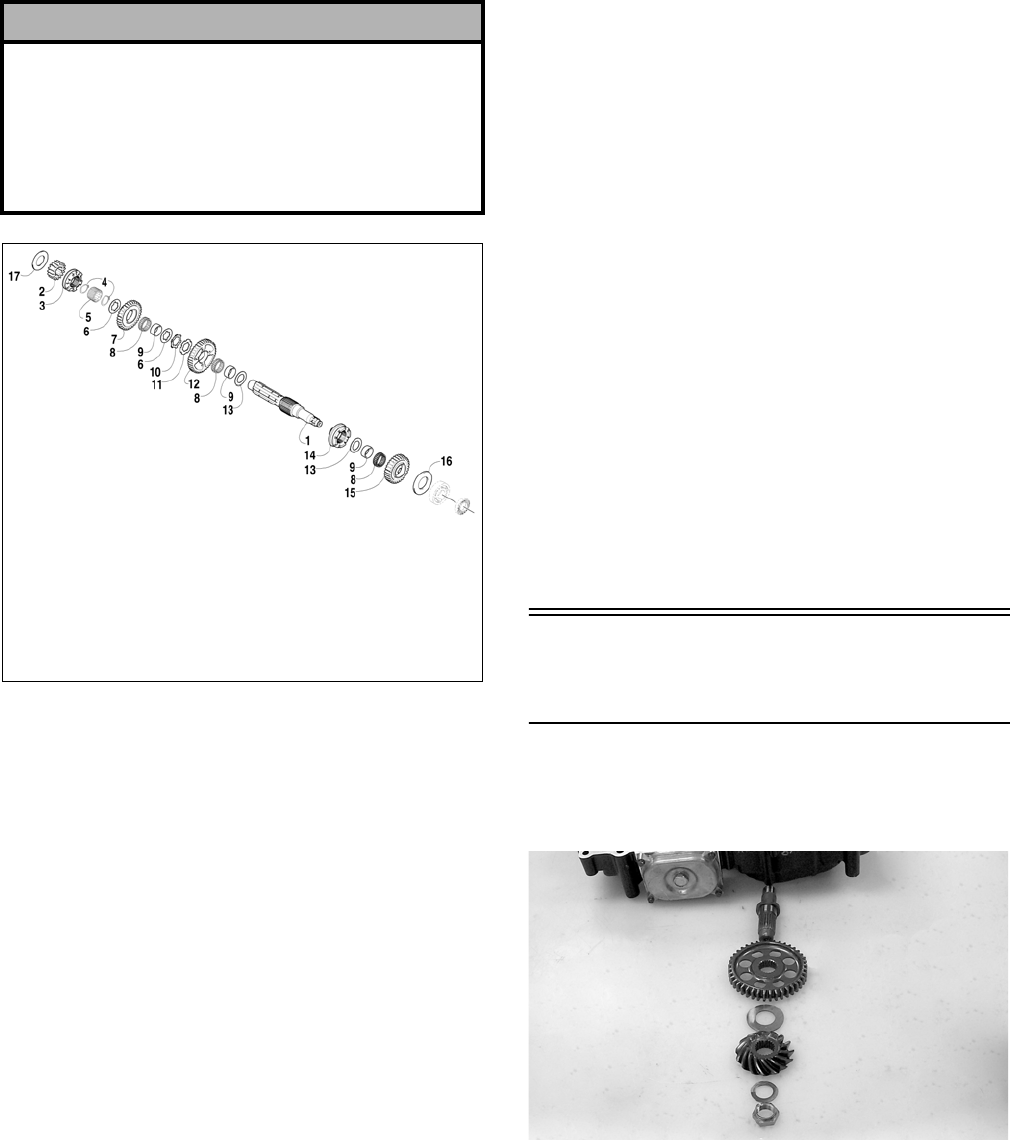
3-166
COUNTERSHAFT
739-954A
Disassembling
From the right side:
1. Remove the right drive gear washer (17); then
remove drive gear #2 (2).
2. Remove the reverse driven gear dog (3); then
remove the circlip (4).
3. Remove the reverse driven gear spacer (5); then
remove the circlip (4).
4. In order, remove washer (6), reverse driven gear
(7), bearing (8), and bushing (9).
5. In order, remove washer (6), lock washer (10,
lock washer (11), and low driven gear (12).
6. In order, remove bearing (8), bushing (9), and
driven gear washer (13).
From the left side:
1. Remove the left drive gear washer (16); then
remove the high driven gear (15) and bearing (8).
2. In order, remove bushing (9), driven gear
washer (13), and sliding dog (14).
Assembling
From the left side:
1. Install the sliding dog (14), driven gear washer
(13), and bushing (9).
2. Install bearing (8) and high driven gear (15);
then install the left drive gear washer (16).
From the right side:
1. Install driven gear washer (13), bushing (9),
bearing (8), and low driven gear (12).
2. Install lock washer (11), lock washer (10),
washer (6), and bushing (9).
3. Install bearing (8), reverse driven gear (7),
washer (6), and the circlip (4).
4. Install reverse driven gear spacer (5), circlip (4),
reverse driven gear dog (3), and drive gear #2
(2); then install the right drive gear washer (17).
NOTE: When installing the countershaft assem-
bly, account for the washer on each end of the shaft.
Assembling Crankcase
Half
1. Install the output shaft assembly into the crank-
case making sure the two gears, shim, washer,
and nut are properly sequenced.
CC686
NOTE: The beveled side of the secondary drive
gear must face upward.
2. Apply red Loctite #271 to the threads of the out-
put shaft; then secure with the nut. Tighten nut
to specifications; then using a punch, peen the
nut.
! CAUTION
When disassembling the countershaft, care must be
taken to note the direction each major component
(dog, gear) faces. If a major component is installed
facing the wrong direction, transmission damage
may occur and/or the transmission will malfunction.
In either case, complete disassembly and assembly
will be required.
KEY
1. Countershaft
2. Drive Gear #2
3. Reverse Driven Gear Dog
4. Circlip
5. Reverse Driven Gear Spacer
6. Washer
7. Reverse Driven Gear
8. Bearing
9. Bushing
10. Lock Washer
11. Lock Washer
12. Low Driven Gear
13. Driven Gear Washer
14. Sliding Dog
15. High Driven Gear
16. Drive Gear Washer (L)
17. Drive Gear Washer (R)
FOR ARCTIC CAT ATV DISCOUNT PARTS CALL 606-678-9623 OR 606-561-4983
www.mymowerparts.com
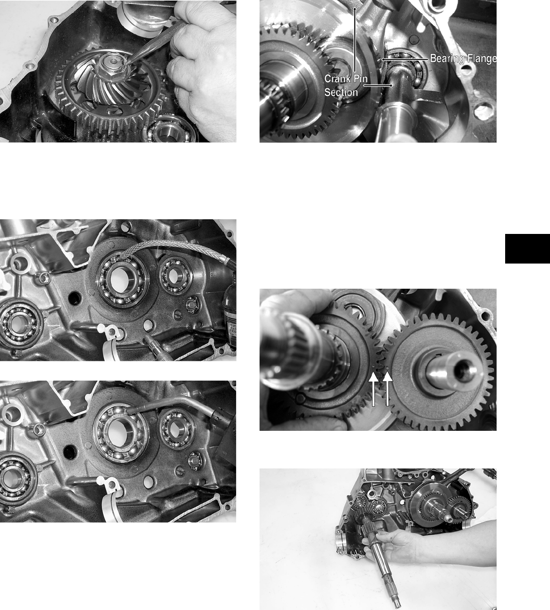
3-167
3
CC687
3. Apply a liberal amount of engine oil to the
crankshaft bearing. Using a propane torch, heat
the bearing until the oil begins to smoke; then
slide the crankshaft assembly into place.
CC688
CC689
NOTE: If heating the bearing is not possible, the
crankshaft can be installed using a crankshaft
installing tool.
4. Install the crank balancer.
CD832B
NOTE: It will be necessary to rotate the crank
balancer until the counterweight is facing away
from the crankshaft; then rotate the crankshaft
clockwise into the journal area to allow the crank
balancer to be fully seated.
5. Place the key into the crank balancer keyway;
then install the crank balancer gear making sure
the alignment dots on the crank balancer gear
and the crankshaft gear align.
CD826A
6. Install the driveshaft.
CC675
7. Place a washer on each end of the countershaft
assembly; then install the assembly.
FOR ARCTIC CAT ATV DISCOUNT PARTS CALL 606-678-9623 OR 606-561-4983
www.mymowerparts.com
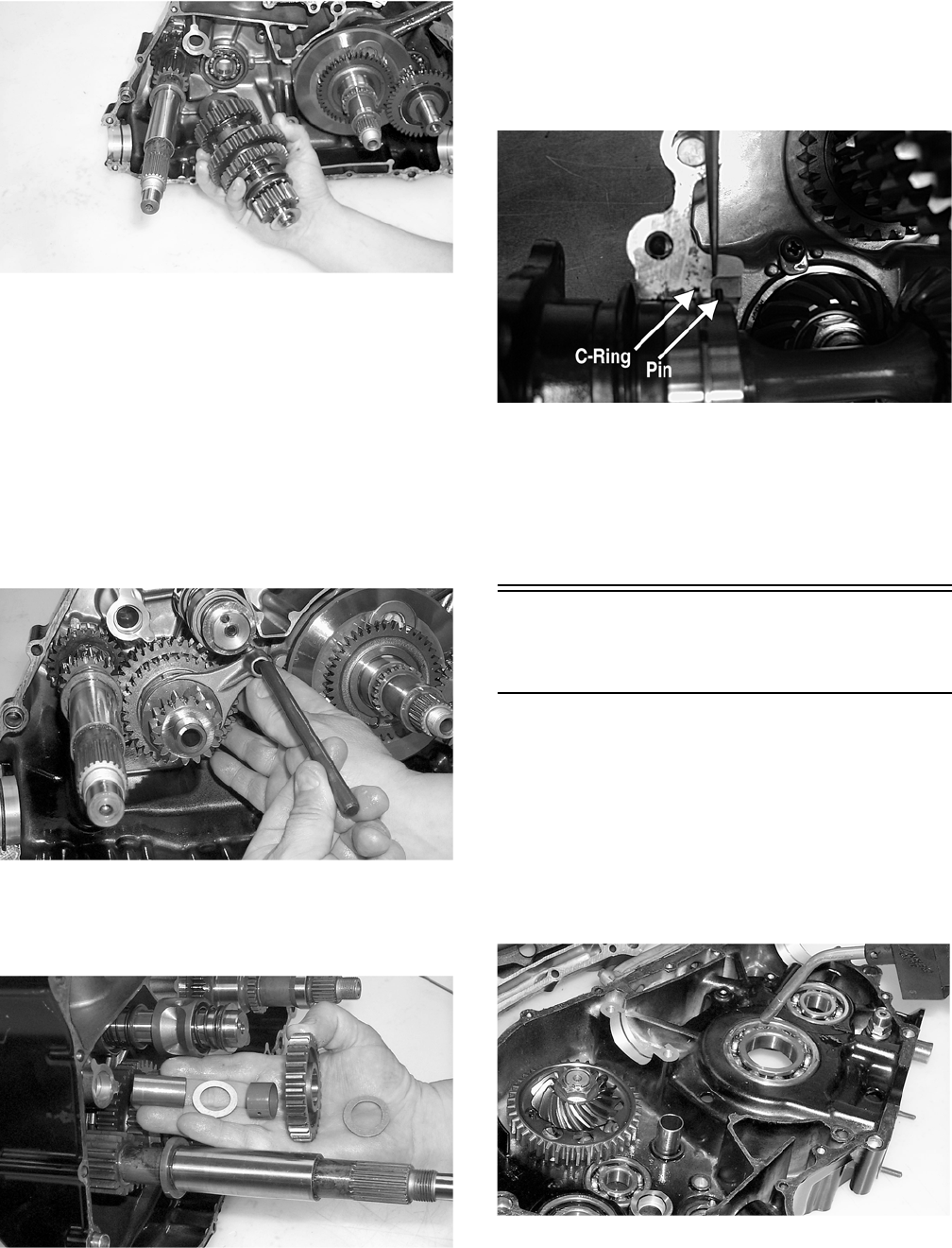
3-168
CC674
8. Place a washer on each end of the gear shift shaft;
then install the shaft assembly making sure the two
holes on the end of the shaft are positioned
vertically.
9. Insert the two shift forks into the sliding dogs
noting the direction of the tabs from disassem-
bling; then install the shift fork shaft.
NOTE: Make sure the shift fork tabs face upward
and that they are properly seated into the shift
cams.
CC669
10. Install the reverse idler gear assembly noting the
positioning of the two washers, gear, bushing,
and shaft.
CC668
11. Install the front and rear secondary driven shaft
assemblies into the left side of the crankcase
making sure the bearing locating pins are facing
upward and the bearing C-ring is fully seated in
the crankcase.
CD268A
12. Place the oil strainer into position; then secure
with the two screws.
13. Place the oil strainer cap into position making
sure the O-ring is in position; then secure the
cap with cap screws. Tighten securely.
Joining Crankcase
Halves
1. Apply High-Temp Sealant to the left-side mat-
ing surface.
2. Lightly oil all bearings and grease all shafts in
the right-side crankcase.
3. Using a propane torch, heat the right-side crank-
shaft bearing until the oil begins to smoke; then
join the two crankcase halves.
CC695
4. Using a plastic mallet, lightly tap the case halves
together until cap screws can be installed.
5. From the right side, install the 8 mm cap screws;
then tighten only until snug.
FOR ARCTIC CAT ATV DISCOUNT PARTS CALL 606-678-9623 OR 606-561-4983
www.mymowerparts.com
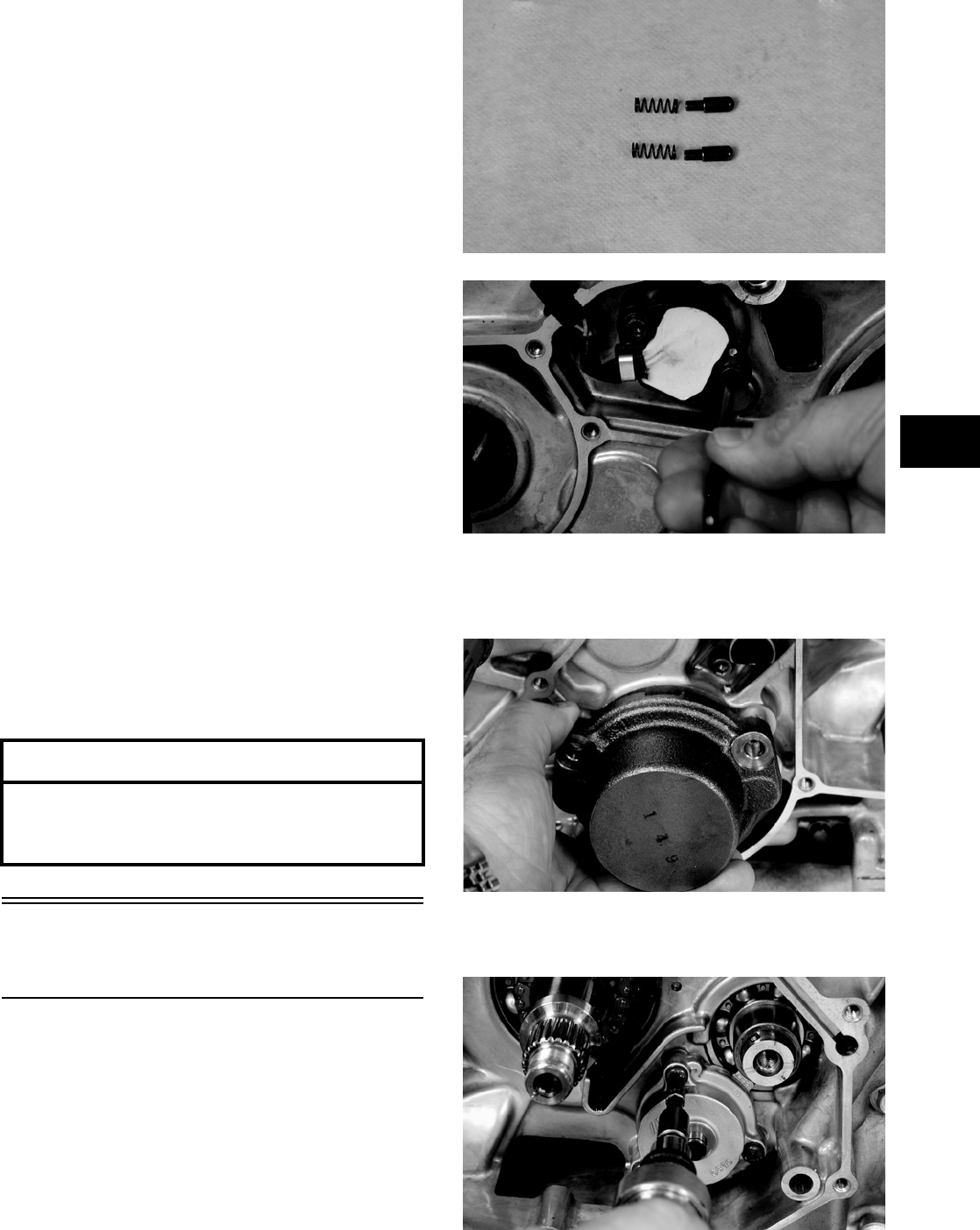
3-169
3
NOTE: Rotate the shafts back and forth to
ensure no binding or sticking occurs.
6. From the left side, install the remaining 8 mm
cap screws (two inside the case); then tighten
only until snug.
NOTE: Rotate the shafts back and forth to
ensure no binding or sticking occurs.
7. From the left side, install the case half 6 mm cap
screws; then tighten only until snug.
NOTE: Rotate the shafts back and forth to
ensure no binding or sticking occurs.
8. From the right side, install the 6 mm cap screws;
then tighten only until snug.
NOTE: Rotate the shafts back and forth to
ensure no binding or sticking occurs.
9. In a crisscross/case-to-case pattern, tighten the 8
mm cap screws (from steps 5-6) until the halves
are correctly joined; then tighten to specifica-
tions.
NOTE: Rotate the shafts back and forth to
ensure no binding or sticking occurs.
10. In a crisscross/case-to-case pattern, tighten the 6
mm cap screws (from steps 7-8) to specifica-
tions.
NOTE: Rotate the shafts back and forth to
ensure no binding or sticking occurs.
Installing Right-Side
Components
1. Install the shift indicator sending unit making
sure the two neutral contact pins and the two
springs are properly positioned. Tighten the
Allen-head screws securely.
CD997
CD994
2. Install the secondary shaft bearing housing mak-
ing sure the two alignment pins are properly posi-
tioned. Tighten the Allen-head screws securely.
CD999
3. Install the oil pump onto the engine; then tighten
the Phillips-head screws securely.
CD988
AT THIS POINT
After completing center crankcase components,
proceed to Installing Right-Side Components, to
Installing Left-Side Components, and to In-
stalling Top-Side Components.
FOR ARCTIC CAT ATV DISCOUNT PARTS CALL 606-678-9623 OR 606-561-4983
www.mymowerparts.com
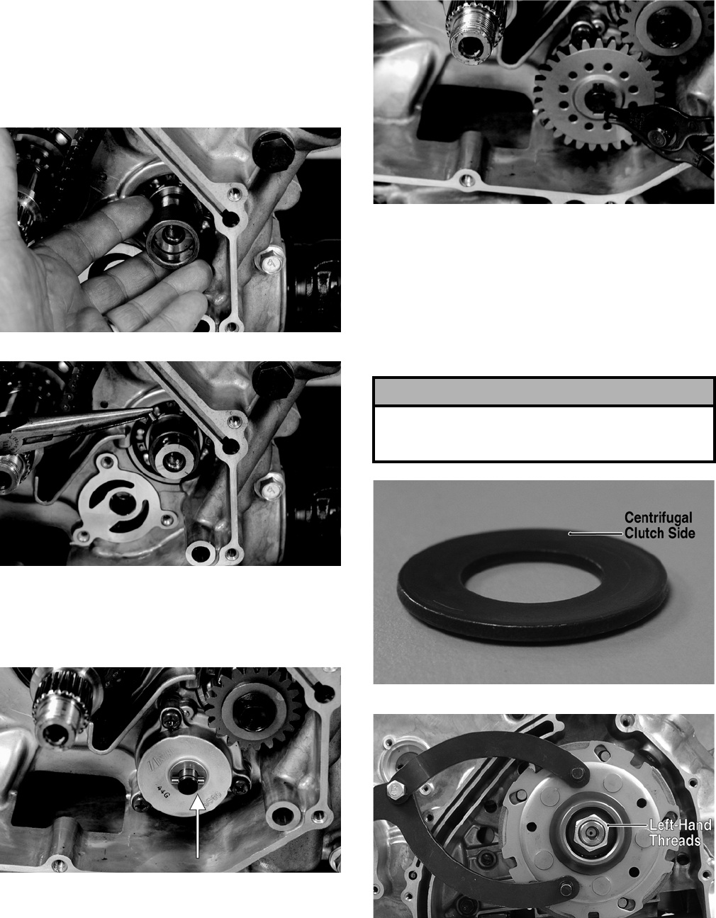
3-170
4. Install the oil pump drive gear spacer onto the
crank balancer shaft. Grease the pin and insert it
into the shaft; then install the drive gear making
sure the raised side of the gear is facing toward
the inside. Secure the gear with the cap screw
(threads coated with red Loctite #271) and the
washer. Tighten the cap screw to specifications.
CD992
CD991
5. Grease the driven gear pin and insert it into the
oil pump shaft; then install the driven gear (not-
ing the direction of the sides of the gear from
removing). Secure with a snap ring.
CD985A
CD984
NOTE: When installed correctly, the sides of the
drive and driven gears will be flush with each other.
6. Install the clutch shoe assembly and secure with
the washer (with the flat side facing the assem-
bly as noted in removing) and the nut (threads
coated with red Loctite #271). Tighten to speci-
fications.
FI336A
FI279A
7. Lightly grease the clutch housing seal; then
insert the left fixed drive spacer.
! CAUTION
Care must be taken that the directional washer be
installed correctly and note that the nut has
left-hand threads.
FOR ARCTIC CAT ATV DISCOUNT PARTS CALL 606-678-9623 OR 606-561-4983
www.mymowerparts.com
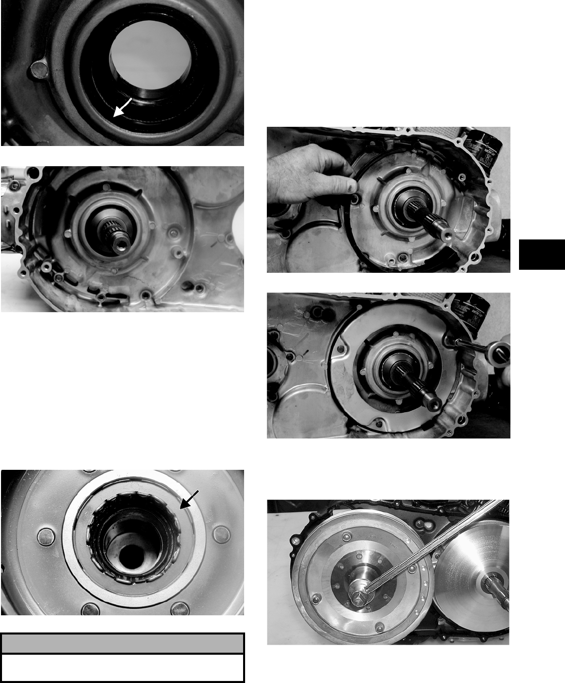
3-171
3
CF088A
CF086
8. Install the clutch cover alignment pins into the
crankcase, apply oil to the cover gasket, and
install the gasket onto the crankcase.
9. Apply grease to the outer edges of the clutch
housing; then from inside the clutch cover,
install the clutch housing into the cover using a
rubber mallet.
10. Install the one-way clutch onto the clutch shoe
assembly.
CF084A
11. Place the clutch cover/clutch housing assembly
into position on the crankcase; then secure with
the cap screws making sure the differ-
ent-lengthed cap screws are in their proper loca-
tion. Tighten to specifications.
12. Place the air intake plate cushion into position;
then install the air intake plate. Tighten the cap
screws (threads treated with a small amount of
red Loctite #271) securely.
CD971
CD970
13. Place the driven pulley assembly into position
and secure with the nut. Tighten to specifica-
tions.
CC726
14. Slide the fixed drive face onto the shaft.
! CAUTION
When installed correctly, the green alignment dot (or
the word OUTSIDE) on the one-way clutch is visible.
FOR ARCTIC CAT ATV DISCOUNT PARTS CALL 606-678-9623 OR 606-561-4983
www.mymowerparts.com
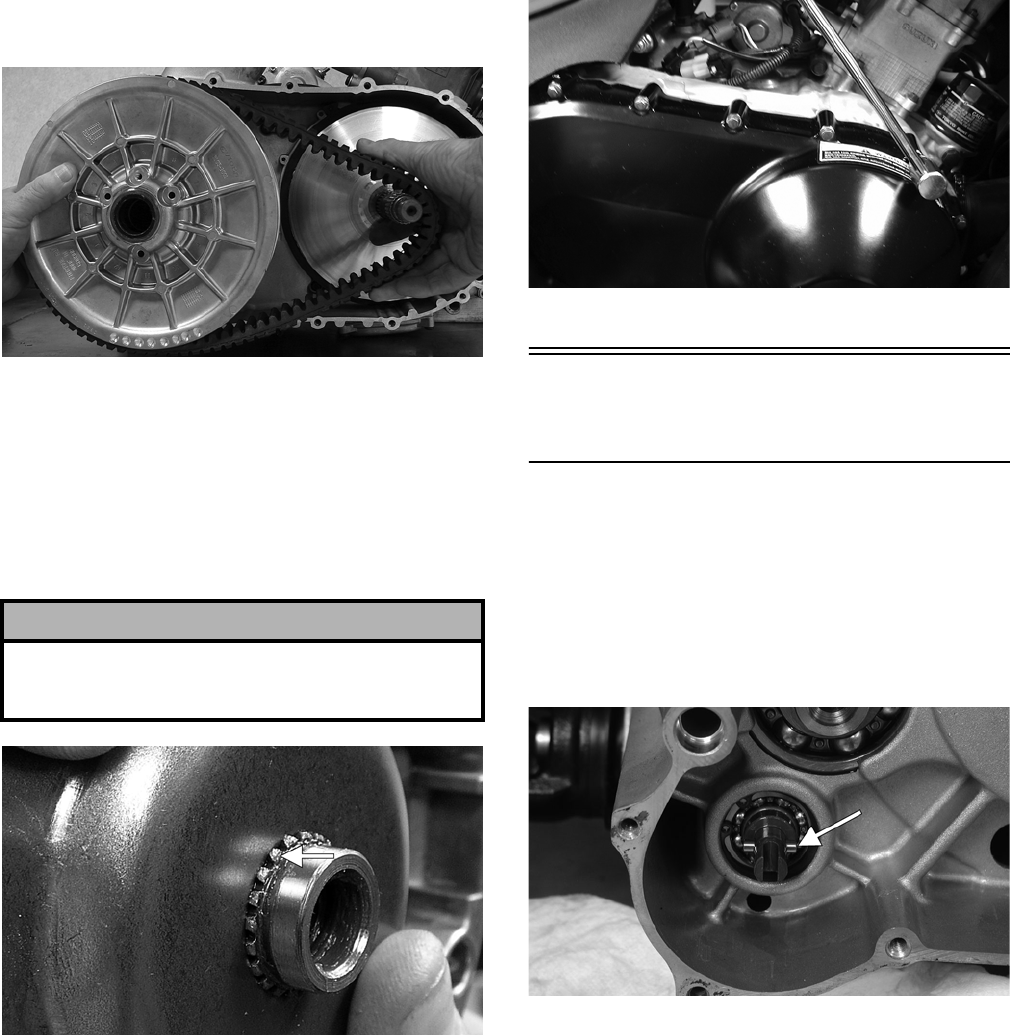
3-172
15. Spread the faces of the driven pulley by pushing
the inner face toward the engine while turning it
counterclockwise; then when the faces are sepa-
rated, insert a wedge (approximately 3/8 in.
thick) between the faces. Release the inner face.
16. Place the V-belt into position on the driven pul-
ley and over the front shaft.
PR389
NOTE: The arrows on the V-belt should point for—
ward.
17. Pinch the V—belt together near its center and
slide the spacer and movable drive face onto the
shaft. Secure the drive face with a nut (threads
coated with red Loctite #271). Tighten the nut to
specifications.
FI428A
NOTE: At this point, the wedge can be removed
from between the driven pulley faces.
18. Rotate the V-belt and drive/driven assemblies
until the V—belt is flush with the top of the driven
pulley.
19. Place the V-belt cover gasket into position; then
install the cover and secure with the cap screws
making sure the different-lengthed cap screws
are in their proper location. Tighten the cap
screws to specifications.
CD083
Installing Left-Side
Components
NOTE: Plug the oil passage in the crankcase
housing prior to installing the drive gear/driven
gear assembly to prevent loss of an alignment pin.
1. Install the water pump driven gear alignment pin
and the driven gear (with the beveled side of the
gear facing outward as noted in removing); then
secure with the snap ring.
CD950A
! CAUTION
Make sure the splines extend beyond the drive face
or a false torque reading and spline damage may
occur.
FOR ARCTIC CAT ATV DISCOUNT PARTS CALL 606-678-9623 OR 606-561-4983
www.mymowerparts.com
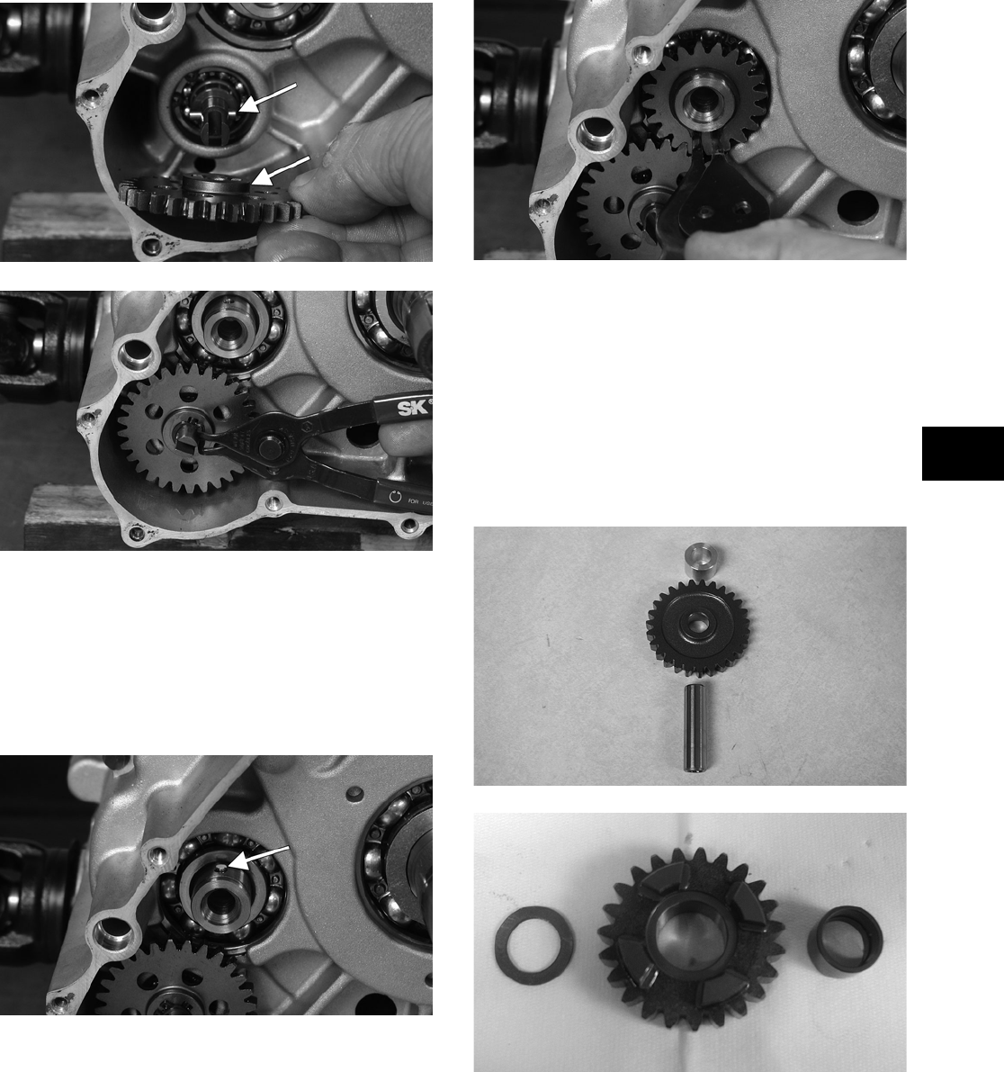
3-173
3
CD952A
CD949
NOTE: The sharp side of the snap ring should be
facing outward.
2. Install the water pump drive gear drive pin and
the drive gear (with the flat side of the gear fac-
ing outward as noted in removing); then secure
with the snap ring.
CD946A
CD944
NOTE: The sharp side of the snap ring should be
facing outward.
NOTE: Once the gears are secured, remove the
oil passage plug from the crankcase.
3. Install the two starter gear shafts; then install the
two starter gears (with the beveled side of the
intermediate gear facing inward as noted in
removing).
CD139
CD145
4. In order on the crankshaft, install a washer, ring
gear, key, and the magneto rotor. Secure with the
nut (threads coated with red Loctite #271).
Tighten to specifications.
FOR ARCTIC CAT ATV DISCOUNT PARTS CALL 606-678-9623 OR 606-561-4983
www.mymowerparts.com
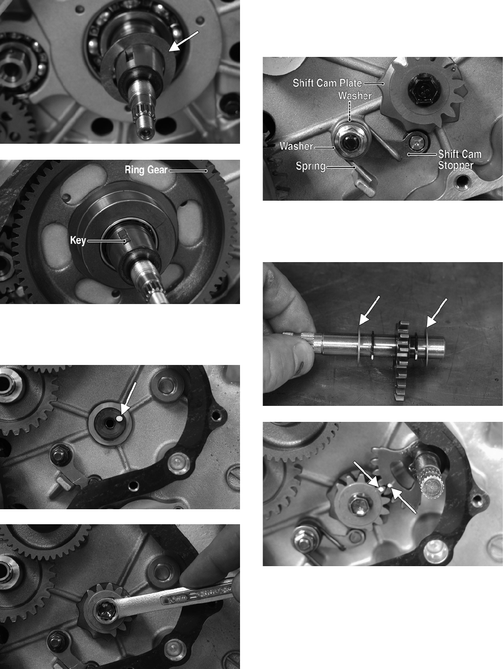
3-174
CD948A
CD940B
5. Install the shift cam plate onto the shift cam
shaft; then coat the cap screw threads with red
Loctite #271 and tighten securely.
CD935A
CD934
6. Install the shift cam stopper, spring, and two
washers; then coat the threads on the mounting
stud with red Loctite #271 and install the nut.
Tighten securely.
PR434A
7. Install the shift shaft with two washers making
sure to align the timing mark on the shift shaft
with the mark on the shift cam plate.
CD954A
CD927A
8. Lubricate the magneto cover gasket with fresh
engine oil; then place it into position on the two
alignment pins. Make sure the outer shift shaft
washer is in place.
FOR ARCTIC CAT ATV DISCOUNT PARTS CALL 606-678-9623 OR 606-561-4983
www.mymowerparts.com
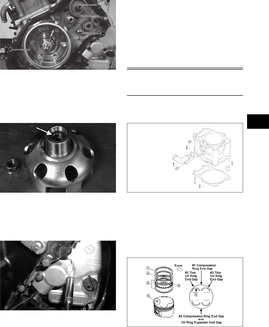
3-175
3
PR431A
9. Install the magneto cover and secure with the
cap screws. Tighten only until snug.
10. Place the starter cup/spacer into position on the
crankshaft making sure a new, lubricated O-ring
is inside the cup/spacer. Tighten the flange nut
to specifications.
CD925A
11. Tighten the cap screws (from step 9) to specifi-
cations.
12. Place the speed sensor housing and gasket into
position and secure with the two cap screws.
Tighten securely.
CD069
13. Place the water pump into position and secure
with two cap screws. Tighten securely.
14. Install the crossover tube on the water pump and
cylinder head making sure the O-ring is properly
positioned.
15. Install the shift arm on the shift arm shaft mak-
ing sure the scribed marks (from removing) are
aligned. Tighten securely.
16. Place the gasket and recoil starter/outer magneto
cover into position on the left-side cover; then
tighten four cap screws to specifications.
Installing Top-Side
Components
A. Piston
B. Cylinder
0732-301
NOTE: If the piston rings were removed, install
them in this sequence.
A. Install ring expander (4) in the bottom groove
of the piston; then install the thin oil rings (3)
over the expander making sure the expander
ends do not overlap. Stagger the end gaps of
the upper and lower thin oil rings according
to the illustration.
ATV-1085B
NOTE: Note the direction of the exhaust side of
the piston (5) for correct ring end gap orientation.
!LIGNMENT0IN
!LIGNMENT0IN
-AGNETO#OVER’ASKET
3HIFT3HAFT7ASHER
KEY
1. Cylinder
2. Stud Bolt
3. Nut
4. Cylinder Gasket
5. Pin
6. Water Hose Union
7. Cap Screw
8. O-Ring
FOR ARCTIC CAT ATV DISCOUNT PARTS CALL 606-678-9623 OR 606-561-4983
www.mymowerparts.com
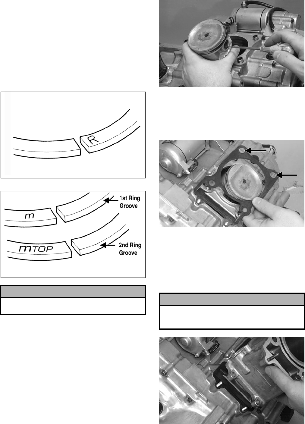
3-176
B. Install the compression rings (1 and 2) so the
letter on the top surface of each ring faces the
dome of the piston. Rotate the rings until the
ring end gaps are on directly opposite sides of
the piston (see illustration).
NOTE: On the 500, the chrome (silver) ring
should be installed in the top position. On the 650
H1, the ring with the orientation mark (MTOP)
should be installed in the second (middle) groove
and the ring with the orientation mark (M) should
be installed in the first (top) groove.
ATV-1024
ATV-1024A
1. Install the piston on the connecting rod making
sure there is a circlip on each side and the open
end of the circlip faces upwards.
NOTE: The piston should be installed so the
arrow points toward the exhaust.
CC032D
2. Place the two alignment pins into position. Place
the cylinder gasket into position; then place a
piston holder (or suitable substitute) beneath the
piston skirt and square the piston in respect to
the crankcase.
CC025D
3. Lubricate the inside wall of the cylinder; then
using a ring compressor or the fingers, compress
the rings and slide the cylinder over the piston.
Route the cam chain up through the cylinder
cam chain housing; then remove the piston
holder and seat the cylinder firmly on the crank-
case.
CC024D
! CAUTION
Incorrect installation of the piston rings will result in
engine damage.
! CAUTION
The cylinder should slide on easily. Do not force the
cylinder or damage to the piston, rings, cylinder, or
crankshaft assembly may occur.
FOR ARCTIC CAT ATV DISCOUNT PARTS CALL 606-678-9623 OR 606-561-4983
www.mymowerparts.com

3-177
3
4. Loosely install the two nuts which secure the
cylinder to the crankcase.
NOTE: The two cylinder-to-crankcase nuts will
be tightened in step 10.
CC023D
5. Install the coolant hose onto the crankcase union
and tighten the clamp.
C. Cylinder Head
D. Valve Cover
0737-755
NOTE: Steps 1-5 in the preceding sub-section
must precede this procedure.
6. Place the chain guide into the cylinder.
CC022D
7. Place the head gasket into position on the cylin-
der. Place the alignment pins into position; then
place the head assembly into position on the cyl-
inder.
CC020D
CF057A
8. Install the four cylinder head cap screws with
copper washers (note the locations of the differ-
ent-lengthed cap screws). Tighten only until
snug.
KEY
1. Cylinder Head
Assy
2. Valve Guide
3. Pin
4. Cap Screw
5. Cap Screw
6. Cylinder Head
Gasket
7. Pin
8. Cap Screw
9. Cap Screw
10. Stud Bolt
11. Stud Bolt
12. Stud Bolt
13. Cap Screw
14. Cap Screw
15. Nut
16. Nut
17. Gasket
18. Gasket
19. Spark Plug
20. Inspection Cap
21. O-Ring
22. Cap Screw
23. Stud Bolt
24. Cylinder Head
Plug
25. Intake Pipe
Assy
26. O-Ring
27. Cap Screw
28. Clamp
29. Temperature
Switch Assy
30. Thermostat
Cover
31. Thermostat
*Frost Plug
*Not Illustrated
! CAUTION
Care should be taken that the bottom of the chain
guide is secured in the crankcase boss.
FOR ARCTIC CAT ATV DISCOUNT PARTS CALL 606-678-9623 OR 606-561-4983
www.mymowerparts.com
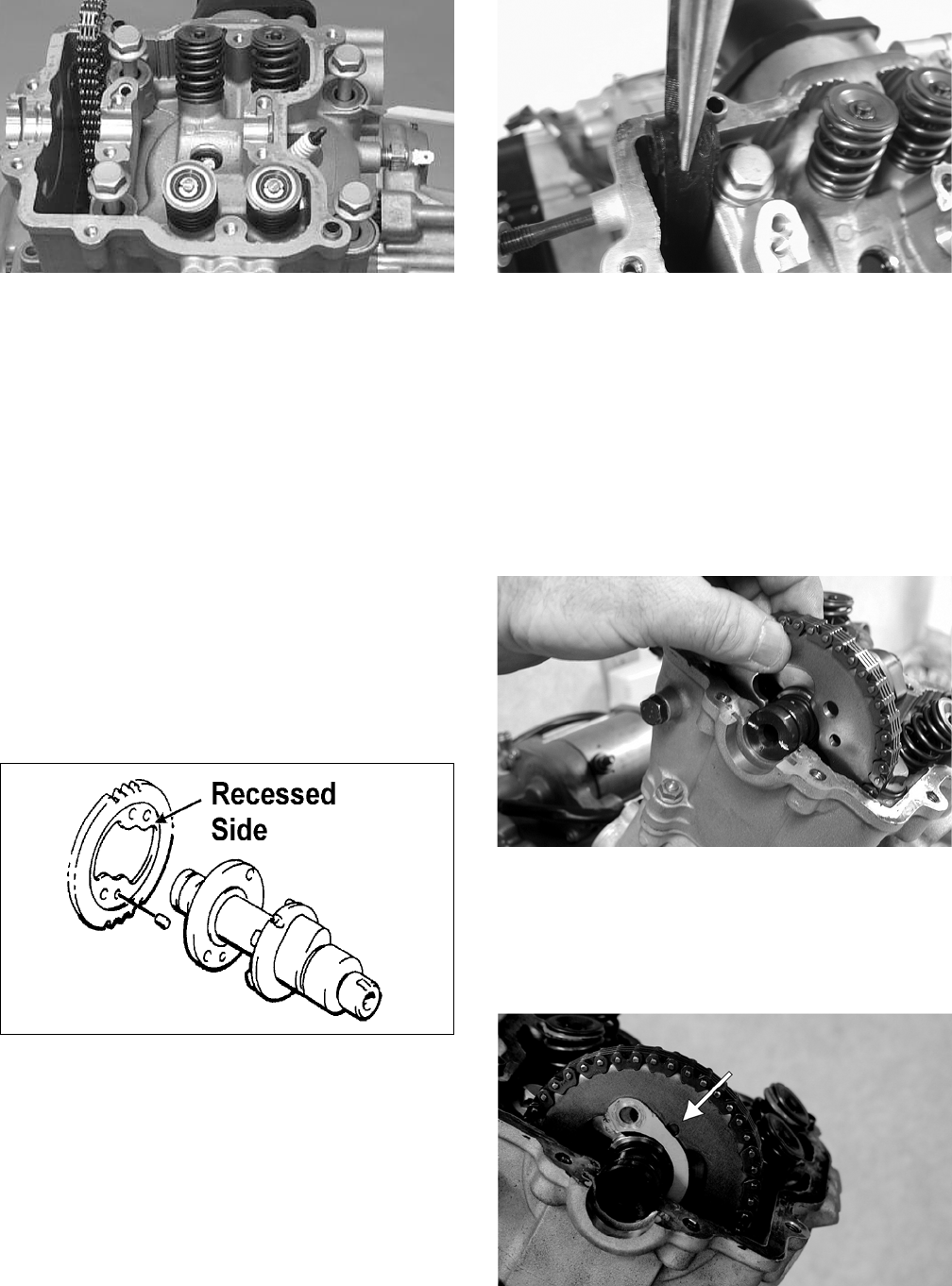
3-178
CC272D
9. Loosely install the five cylinder head nuts.
10. In a crisscross pattern, tighten the four cylinder
head cap screws (from step to 3.8 kg-m (27.5
ft-lb) 500 models, 5.5 kg-m (40 ft-lb) 650 H1;
then tighten the 8 mm nut (from step 9) to 2.5
kg-m (18 ft-lb). Using a crisscross pattern,
tighten the 6 mm nuts (from step 9) to 1.1 kg-m
(8 ft-lb). Tighten the two cylinder-to- crankcase
nuts (from step 4) securely.
11. With the timing inspection plug removed and
the chain held tight, rotate the crankshaft until
the piston is at top-dead-center.
12. With the alignment pin installed in the camshaft,
loosely place the cam sprocket (with the
recessed side facing the cam shaft lobes) onto
the camshaft. At this point, do not “seat” the
sprocket onto the shaft.
732-307B
NOTE: At this point, oil the camshaft bearings,
cam lobes, and the three seating journals on the
cylinder.
13. While holding the cam chain sprocket to the
side, install the rear cam chain tensioner guide
into the cylinder head. Install the pivot cap
screw and washer.
CD461
14. With the cam lobes directed down (toward the
piston), maneuver the camshaft/sprocket assem-
bly through the chain and towards its seating
position; then loop the chain over the sprocket.
NOTE: Note the position of the alignment marks
on the end of the camshaft. They must be parallel
with the valve cover mating surface. If rotating the
camshaft is necessary for alignment, do not allow
the chain and sprocket to rotate and be sure the
cam lobes end up in the down position.
CD463
15. Seat the cam sprocket onto the camshaft making
sure the alignment pin in the camshaft aligns
with the smallest hole in the sprocket; then place
the camshaft/sprocket assembly onto the cylin-
der ensuring the following.
CF013A
A. Piston still at top-dead-center.
FOR ARCTIC CAT ATV DISCOUNT PARTS CALL 606-678-9623 OR 606-561-4983
www.mymowerparts.com
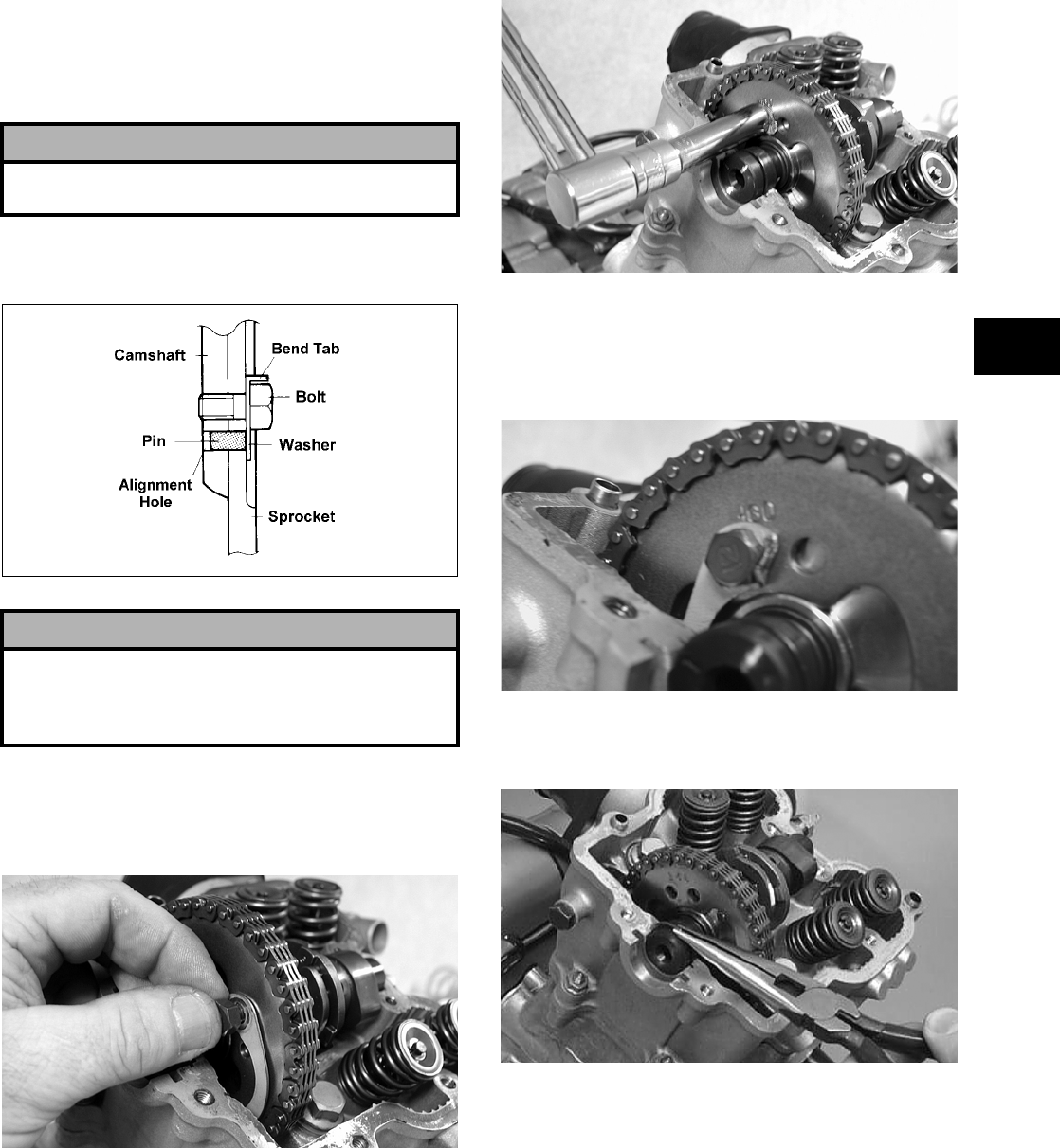
3-179
3
B. Camshaft lobes directed down (toward the
piston).
C. Camshaft alignment marks parallel to the
valve cover mating surface.
D. Recessed side of the sprocket directed toward
the cam lobes.
E. Camshaft alignment pin and sprocket align-
ment hole (smallest) are aligned.
16. Place the tab-washer onto the sprocket making
sure it covers the pin in the alignment hole.
ATV1027
17. Install the first cap screw (threads coated with
red Loctite #271) securing the sprocket and
tab-washer to the camshaft. Tighten only until
snug.
CD464
18. Rotate the crankshaft until the second cap screw
securing the sprocket to the camshaft can be
installed; then install the cap screw (threads
coated with red Loctite #271) and tighten to spec-
ifications. Bend the tab to secure the cap screw.
CD465
19. Rotate the crankshaft until the first cap screw
(from step 17) can be addressed; then tighten to
specifications. Bend the tab to secure the cap
screw.
CD466
20. Place the C-ring into position in its groove in the
cylinder head.
CC012D
21. Install the cylinder head plug in the cylinder
head with the open end facing downward and
toward the inside.
! CAUTION
If any of the above factors are not as stated, go back
to step 11 and carefully proceed.
! CAUTION
Care must be taken that the tab-washer is installed
correctly to cover the alignment hole on the
sprocket. If the alignment pin falls out, severe
engine damage will result.
FOR ARCTIC CAT ATV DISCOUNT PARTS CALL 606-678-9623 OR 606-561-4983
www.mymowerparts.com
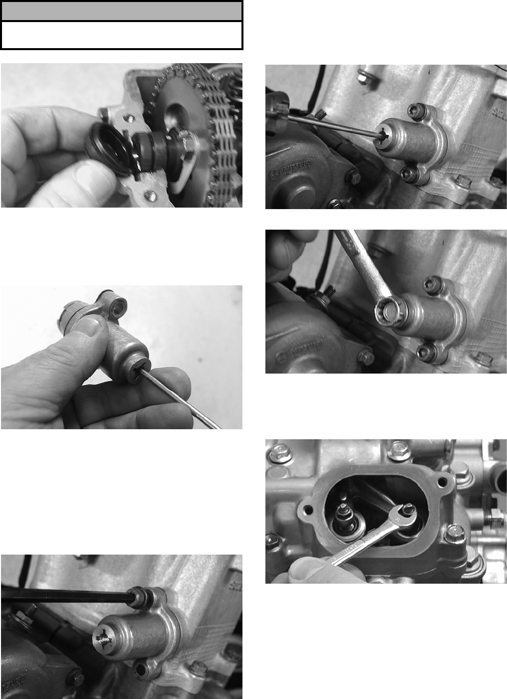
3-180
CD468
22. Remove the cap screw from the end of the chain
tensioner; then using a flat-blade screwdriver,
rotate the adjuster screw inside the tensioner
clockwise until the screw bottoms.
CD501
NOTE: The adjuster shaft will be drawn into the
tensioner as the adjuster screw is rotated clock-
wise. The adjuster shaft tension will be released in
step 24.
23. Place the chain tensioner adjuster assembly and
gasket into position on the cylinder and secure
with the two Allen-head cap screws.
CD469
24. Using a flat-blade screwdriver, rotate the
adjuster screw inside the tensioner counter-
clockwise until all tension is released; then
install the cap screw into the end of the chain
tensioner.
CD470
CD471
25. Loosen the four adjuster screw jam nuts; then
loosen the four adjuster screws on the rocker
arms in the valve cover.
CC005D
26. Apply a thin coat of Three Bond Sealant to the
mating surfaces of the cylinder head and valve
cover.
! CAUTION
The open end of the plug must be positioned down-
ward.
FOR ARCTIC CAT ATV DISCOUNT PARTS CALL 606-678-9623 OR 606-561-4983
www.mymowerparts.com
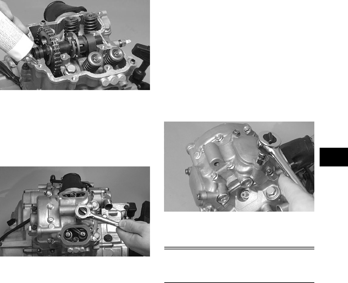
3-181
3
CC275D
27. Place the valve cover into position.
NOTE: At this point, the rocker arms and
adjuster screws must not have pressure on them.
28. Install the four top side cap screws with rubber
washers; then install the remaining cap screws.
Tighten only until snug.
CC003D
29. In a crisscross pattern starting from the center
and working outward, tighten the cap screws
securely.
30. Adjust valve/tappet clearance using the follow-
ing procedure.
NOTE: Use Valve Clearance Adjuster (p/n
0444-078) for this procedure.
A. Turn the engine over until the piston reaches
top dead center on the compression stroke.
B. Place the valve adjuster onto the jam nut
securing the tappet adjuster screw; then rotate
the valve adjuster dial clockwise until the end
is seated in the tappet adjuster screw.
C. While holding the valve adjuster dial in
place, use the valve adjuster handle and
loosen the jam nut; then rotate the tappet
adjuster screw clockwise until friction is felt.
D. Align the valve adjuster handle with one of
the marks on the valve adjuster dial.
E. While holding the valve adjuster handle in
place, rotate the valve adjuster dial counter-
clockwise until specified valve/tappet clear-
ance is attained.
NOTE: Rotating the valve adjuster dial counter-
clockwise will open the valve/tappet clearance by
0.05 mm (0.002 in.) per mark.
F. While holding the adjuster dial at the proper
clearance setting, tighten the jam nut securely
with the valve adjuster handle.
31. Place the two tappet covers into position making
sure the proper cap screws are with the proper
cover. Tighten the cap screws securely.
CC001D
32. If removed, install the spark plug. Tighten to
specifications.
Installing
Engine/Transmission
NOTE: Arctic Cat recommends that new gaskets
and O-rings be installed whenever servicing the
ATV.
1. From the left side, place the engine/transmission
into the frame; then slide the engine rearward as
far as possible.
2. Slightly raise the rear of the engine and engage
the front drive coupler into the splines of the
front drive output yoke; then slide the engine
forward as far as possible.
FOR ARCTIC CAT ATV DISCOUNT PARTS CALL 606-678-9623 OR 606-561-4983
www.mymowerparts.com
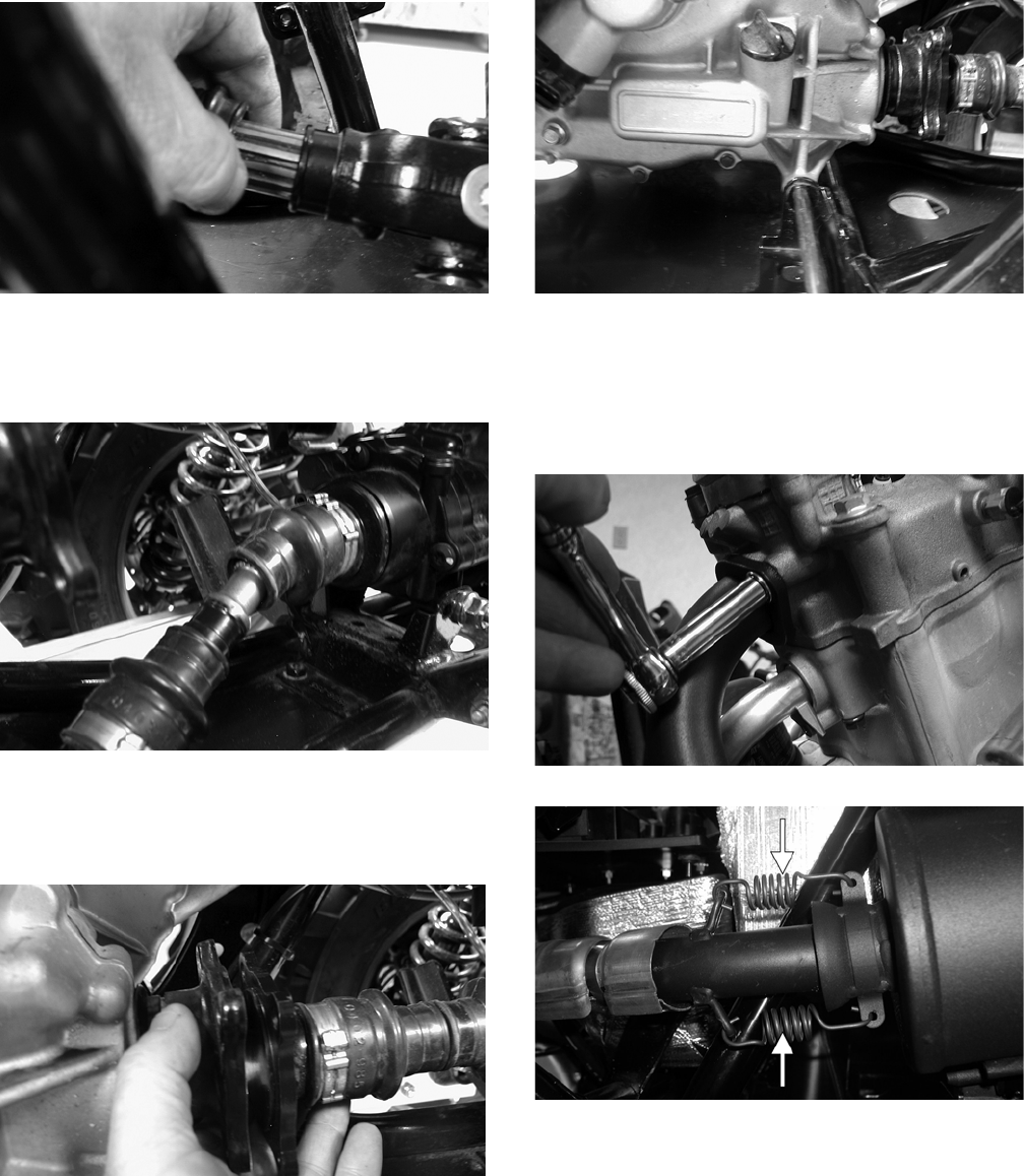
3-182
CD818
3. Raise the rear of the engine and place a block
beneath it; then install the propeller shaft and
output flange into the rear drive coupler.
CD821
4. Remove the block from beneath the engine; then
align the rear drive flanges and secure with four
cap screws. Tighten to specifications.
CD824
5. Install two engine mounting through-bolts, two
bushings, and two washers; then tighten the
through-bolt flange nuts to specifications.
CD809
6. Secure the exhaust pipe to the engine with two
cap screws making sure the mounting brackets
engage the frame grommets; then install the
muffler and tighten all mounting hardware to
specifications.
CD803
CF138A
7. Install the cooling ducts with clamps and tighten
the clamps securely.
FOR ARCTIC CAT ATV DISCOUNT PARTS CALL 606-678-9623 OR 606-561-4983
www.mymowerparts.com
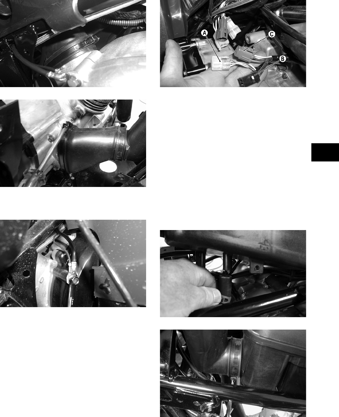
3-183
3
CD515
CD793
8. Secure the engine ground wire to the engine
with a cap screw. Tighten to specifications.
CD810
9. Connect the gear position indicator connector
(A), stator connector (B), and the CDI connector
(C) to the main wiring harness.
CD797A
10. Connect the temperature sensor wire to the main
wiring harness.
11. Secure the wires to the frame with nylon ties.
12. Connect the speed sensor connector to the hous-
ing.
13. Secure the positive cable to the starter motor.
14. Secure all wiring to the frame and upper engine
bracket with cable ties.
15. Secure the two coolant/oil hoses to the engine.
16. Secure the crankcase vent hose to the air cleaner
housing; then secure the inlet boot and carbure-
tor to the air cleaner housing.
CD787
CD785
FOR ARCTIC CAT ATV DISCOUNT PARTS CALL 606-678-9623 OR 606-561-4983
www.mymowerparts.com
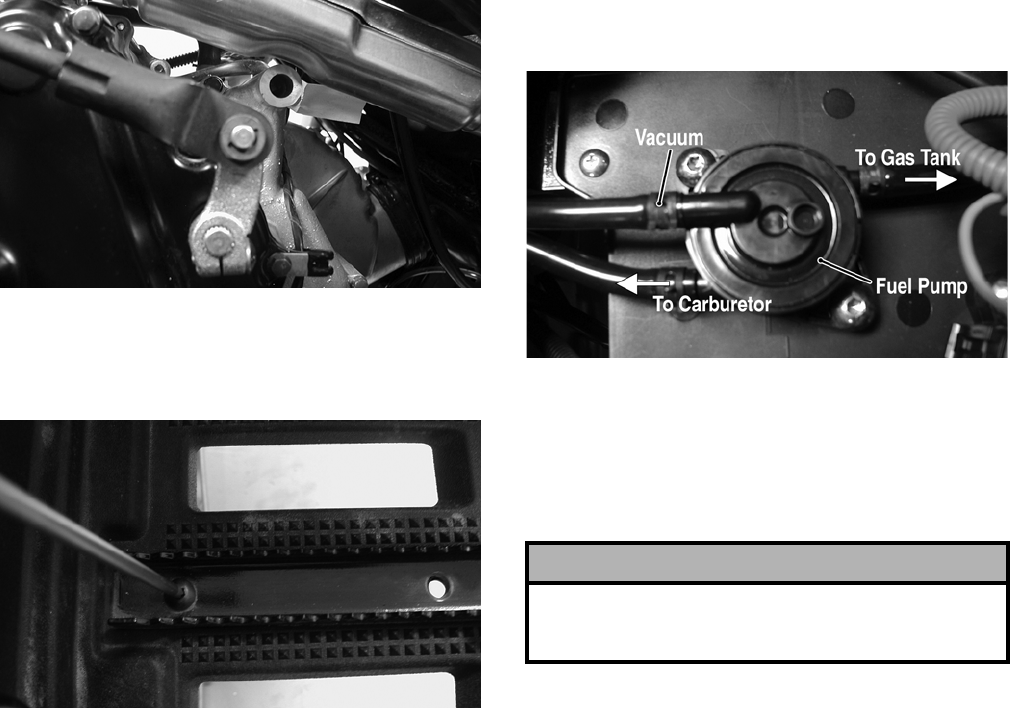
3-184
17. Secure the shift rod to the engine with a new
E-clip.
CD774
18. Place the left-side footwell and foot peg in posi-
tion on the frame; then secure with existing
hardware. Tighten to specifications.
CD782
19. Install the front body panel with existing hard-
ware (see Section 8).
20. Connect the hose to the fuel pump; then connect
the vacuum hose and secure with hose clamps.
CD766A
21. Place the side panels into position; then install
the reinstallable rivets.
22. Place the battery into position in the battery
compartment; then install the battery cables and
vent hose. Secure with the battery cover.
23. Add proper amounts of engine/transmission oil
and coolant.
24. Install the seat.
! CAUTION
Battery acid is harmful if it contacts eyes, skin, or
clothing. Care must be taken whenever handling a
battery.
FOR ARCTIC CAT ATV DISCOUNT PARTS CALL 606-678-9623 OR 606-561-4983
www.mymowerparts.com
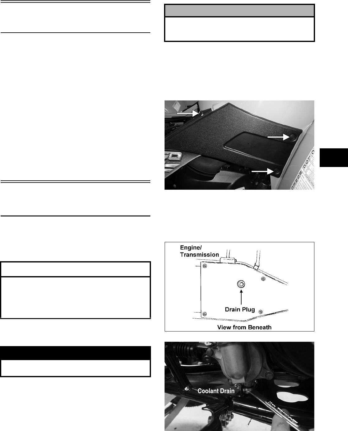
3-185
3
Table of Contents
(500 — Manual Transmission)
Removing Engine Transmission……….……………. 3-185
Top-Side Components……………….…………….…… 3-189
Removing Top-Side Components …….……………. 3-189
Left-Side Components ……………………….………… 3-193
Removing Left-Side Components ….…………….… 3-193
Right-Side Components …………….………….……… 3-198
Removing Right-Side Components…..……………. 3-198
Center Crankcase Components……….……………. 3-202
Separating Crankcase Halves………….……………. 3-202
Disassembling Crankcase Half ……………………… 3-204
Servicing Components………..……………..………… 3-206
Assembling Crankcase Half ………………..………… 3-232
Joining Crankcase Halves……………….………….… 3-235
Installing Right-Side Components…….……………. 3-236
Installing Left-Side Components …………….……… 3-240
Installing Top-Side Components ………………….… 3-245
Installing Engine/Transmission…………….………… 3-251
Removing Engine/
Transmission
Many service procedures can be performed without
removing the engine/transmission from the frame.
Closely observe the note introducing each sub-sec-
tion for this important information.
Secure the ATV on a support stand to elevate the
wheels.
1. Remove the seat.
2. Remove the negative cable from the battery;
then remove the positive cable. Remove the bat-
tery vent hose; then remove the battery.
3. Remove the radiator access cover, steering post
cover, and storage compartment cover assem-
bly; then remove the storage compartment box.
4. Remove the reinstallable rivets securing the side
panels; then remove the panels.
CD683A
5. Remove the instrument pod; then remove the
front rack and front body panel (see Section 8).
6. Drain the oil from beneath the engine/transmis-
sion; then drain the cooling system.
ATV-0109
CD799A
7. Remove the air filter (see Section 2).
AT THIS POINT
If the technician’s objective is to service/replace
left-side cover oil seals (3), front output joint oil
seal (1), rear output joint oil seal (1), and/or the oil
strainer (from beneath the engine/transmission),
the engine/transmission does not have to be
removed from the frame.
! WARNING
Make sure the ATV is solidly supported on the sup-
port stand to avoid injury.
! CAUTION
Battery acid is harmful if it contacts eyes, skin, or
clothing. Care must be taken whenever handling a
battery.
FOR ARCTIC CAT ATV DISCOUNT PARTS CALL 606-678-9623 OR 606-561-4983
www.mymowerparts.com
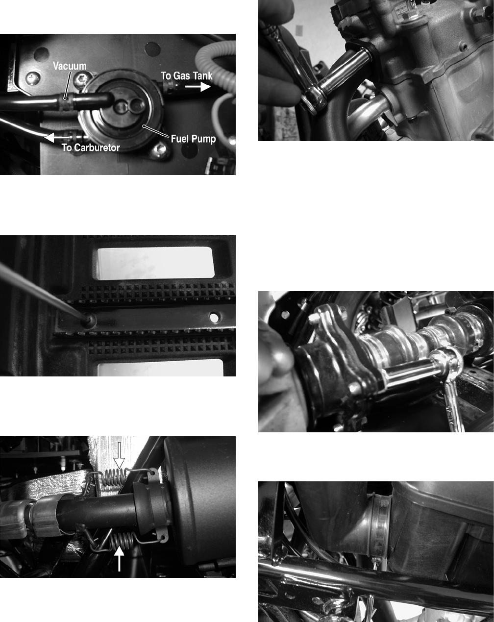
3-186
8. Remove the vacuum hose and the
fuel-pump-to-carburetor hose.
CD766A
9. Remove the cap screws securing the left-side
foot peg and footwell to the footrest; then
remove the footwell.
CD782
10. Remove the springs securing the muffler to the
exhaust pipe; then remove the muffler. Account
for two exhaust springs.
CF138A
11. Remove the cap screws securing the exhaust
pipe to the head; then remove the exhaust pipe.
CD803
12. Remove the E-clip securing the shift rod to the
engine shift arm; then allow the shift rod to
swing forward and hang straight down from the
shift lever.
13. Disconnect the speed sensor connector from the
sensor housing.
14. Remove the four cap screws securing the rear
output joint to the transmission and push the
shaft away from the transmission.
CD805
15. Loosen the clamp securing the air intake duct to
the air filter housing.
CD785
16. Disconnect the crankcase vent hose from the air
filter housing. Loosen the clamp securing the
carburetor intake duct to the air filter housing;
then remove the housing.
FOR ARCTIC CAT ATV DISCOUNT PARTS CALL 606-678-9623 OR 606-561-4983
www.mymowerparts.com
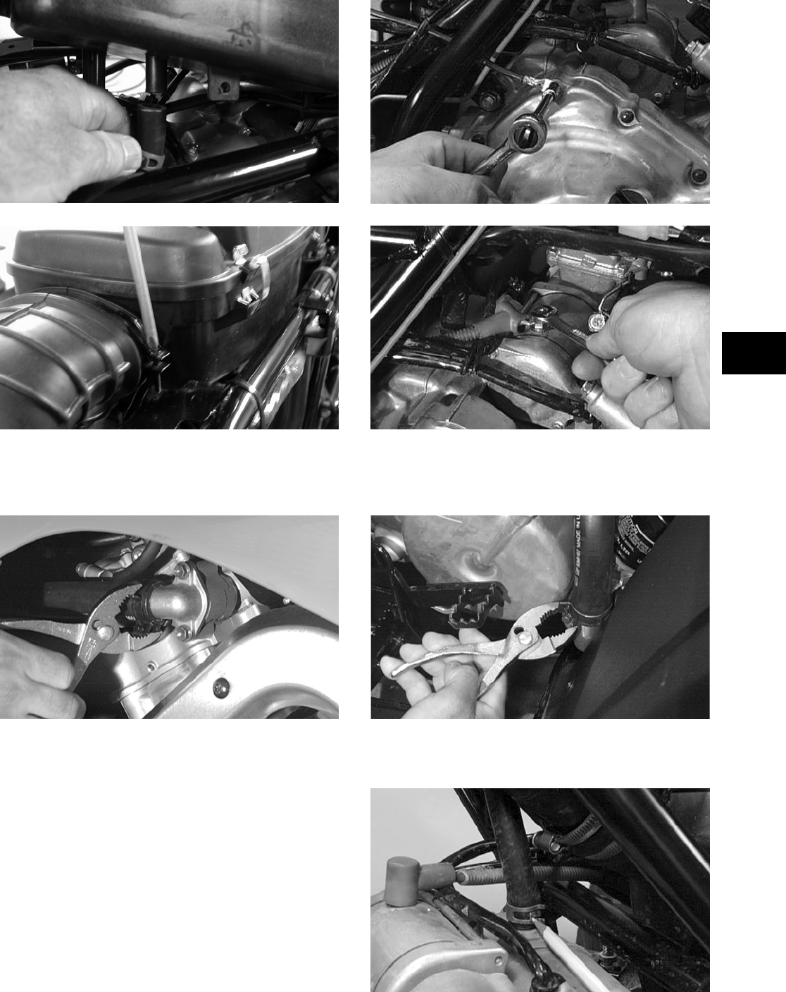
3-187
3
CD787
CD786
17. Remove the clamp securing the upper coolant
hose to the thermostat housing; then disconnect
the hose.
CC335D
18. Disconnect the high tension lead from the spark
plug; then remove the coil.
19. Disconnect the battery ground (negative) cable
from the crankcase cover; then disconnect the
positive cable from the starter motor.
AR600D
AR604D
20. Remove the clamp securing the lower coolant
hose to the water pump housing; then disconnect
the hose.
CC334D
21. Loosen the clamp on the crankcase breather vent
hose; then remove the hose.
CC122D
FOR ARCTIC CAT ATV DISCOUNT PARTS CALL 606-678-9623 OR 606-561-4983
www.mymowerparts.com
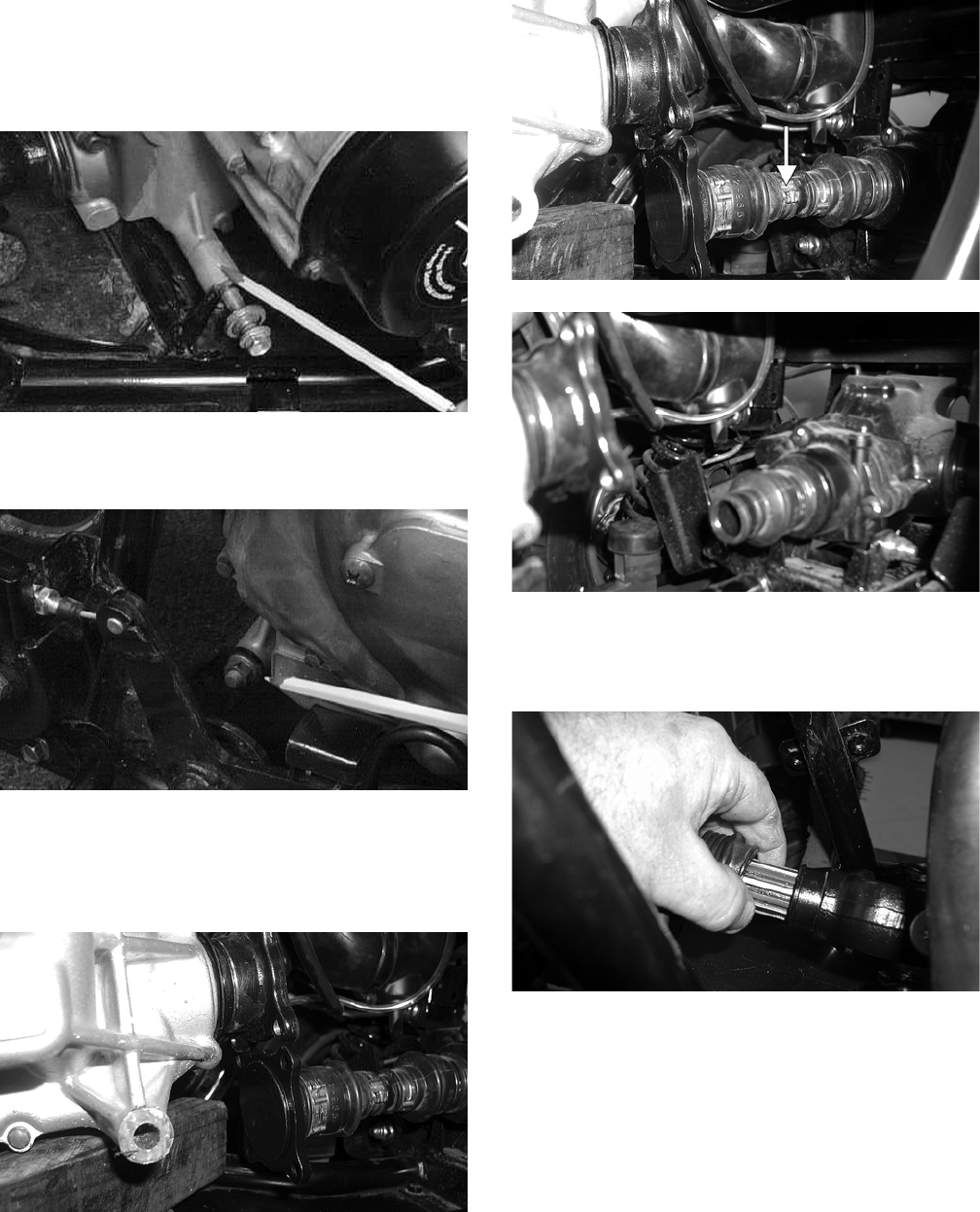
3-188
22. Remove the engine/transmission mounting fas-
teners in the following sequence:
A. Lower front: One cap screw, nut, spacer, and
washer.
CC123D
B. Lower rear: One cap screw, nut, spacer, and
washer.
CC126D
23. Raise the rear of the engine enough to allow the
rear output flange to clear the output flange
joint. Place a block beneath the engine in this
position.
CD811
24. Remove the first small boot clamp; then slide
the output flange and driveshaft out of the rear
coupler.
CD812A
CD813
25. Remove the block and lower the rear of the
engine; then remove the boot clamp on the front
output drive yoke.
CD817
26. Move the engine to the rear enough to allow the
front drive coupler to clear the front output
yoke; then move the engine forward and to the
left. Remove the engine from the left-side of the
frame.
FOR ARCTIC CAT ATV DISCOUNT PARTS CALL 606-678-9623 OR 606-561-4983
www.mymowerparts.com
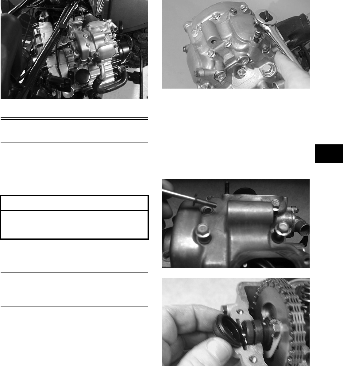
3-189
3
CD773
Top-Side Components
NOTE: For efficiency, it is preferable to remove
and disassemble only those components which
need to be addressed and to service only those
components. The technician should use discretion
and sound judgment.
NOTE: The engine/transmission does not have
to removed from the frame for this procedure.
Removing Top-Side
Components
A. Valve Cover
B. Cylinder Head
NOTE: Remove the spark plug and timing
inspection plug; then using the recoil starter,
rotate the crankshaft to top-dead-center of the
compression stroke.
1. Remove the two tappet covers.
CC001D
NOTE: Keep the mounting hardware with the
covers for assembly purposes or thread them back
into the head to keep them separated.
2. Remove the 12 cap screws securing the valve
cover to the head; account for the four rubber
washers on the top side cap screws. Remove the
valve cover. Account for and note the orienta-
tion of the cylinder head plug. Note the location
of two alignment pins.
CD205
CD468
NOTE: Note that the opening of the head plug
must be directed to the 6 o’clock position.
3. Loosen the cap screw on the end of the ten-
sioner; then remove the two Allen-head cap
screws securing the tensioner adjuster assembly
and remove the assembly. Account for a gasket.
AT THIS POINT
To service any one specific component, only
limited disassembly of components may be
necessary. Note the AT THIS POINT information in
each sub-section.
FOR ARCTIC CAT ATV DISCOUNT PARTS CALL 606-678-9623 OR 606-561-4983
www.mymowerparts.com
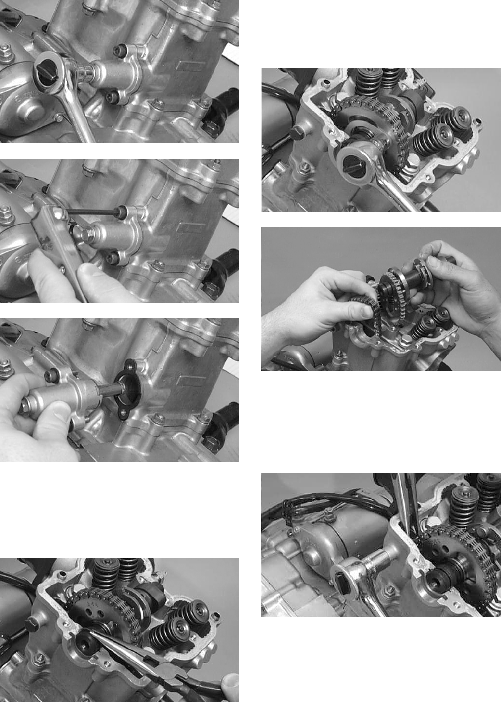
3-190
CC009D
CC010D
CC011D
4. Using an awl, rotate the C-ring in its groove
until it is out of the cylinder head; then remove
the C-ring.
NOTE: Care should be taken not to drop the
C-ring down into the crankcase.
CC012D
5. Bend the washer tabs and remove the two cap
screws securing the sprocket to the camshaft;
then drop the sprocket off the camshaft. While
holding the chain, slide the sprocket and cam-
shaft out of the cylinder head.
CC013D
CC266D
NOTE: Loop the chain over the cylinder and
secure it to keep it from falling into the crankcase.
6. Remove the cap screw securing the chain ten-
sioner (account for a washer); then remove the
tensioner.
CC014D
7. Remove the five nuts securing the cylinder head
to the cylinder; then remove the four cylinder
head cap screws with copper washers (note loca-
tion of the different-sized cap screws and nuts).
FOR ARCTIC CAT ATV DISCOUNT PARTS CALL 606-678-9623 OR 606-561-4983
www.mymowerparts.com
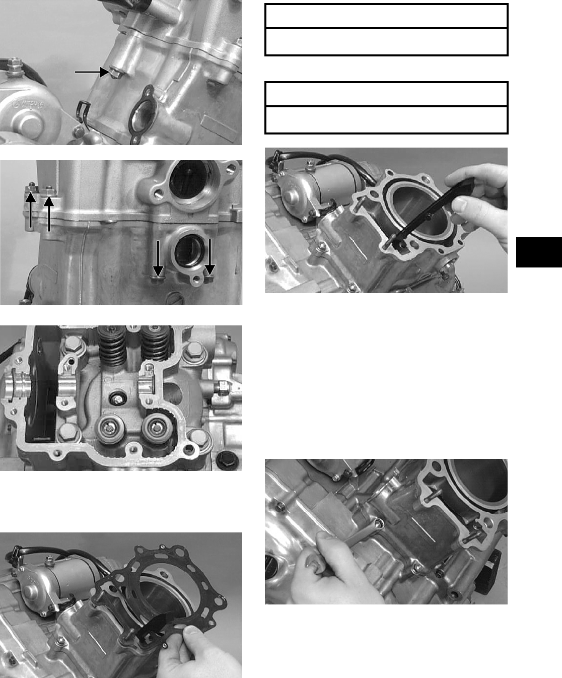
3-191
3
CC017D
CC018D
CC016D
8. Remove the cylinder head from the cylinder,
remove the gasket, and account for two align-
ment pins.
CC020D
9. Remove the cam chain guide.
CC022D
C. Cylinder
D. Piston
NOTE: Steps 1-9 in the preceding sub-section
must precede this procedure.
10. Loosen the clamp securing the coolant hose to
the union; then detach the hose.
11. Remove the two nuts securing the cylinder to
the crankcase.
CC023D
12. Lift the cylinder off the crankcase taking care
not to allow the piston to drop against the crank-
case. Account for the gasket and two alignment
pins.
AT THIS POINT
To service valves and cylinder head, see
Servicing Top-Side Components sub-section.
AT THIS POINT
To inspect cam chain guide, see Servicing
Top-Side Components sub-section.
FOR ARCTIC CAT ATV DISCOUNT PARTS CALL 606-678-9623 OR 606-561-4983
www.mymowerparts.com
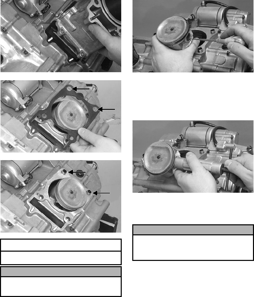
3-192
CC024D
CC025D
CC026D
13. Using an awl, remove one piston-pin circlip.
CC032D
14. Using the Piston Pin Puller (p/n 0644-328),
remove the piston pin. Account for the oppo—
site-side circlip. Remove the piston.
NOTE: It is advisable to remove the oppo-
site-side circlip prior to using the puller.
CC033D
NOTE: Support the connecting rod with rubber
bands to avoid damaging the rod or install the
Connecting Rod Holder (p/n 0444-006).
NOTE: If the existing rings will not be replaced
with new rings, note the location of each ring for
proper installation. When replacing with new rings,
replace as a complete set only. If the piston rings
must be removed, remove them in this sequence.
A. Starting with the top ring, slide one end of the
ring out of the ring-groove.
AT THIS POINT
To service cylinder, see Servicing Top-Side
Components sub-section.
! CAUTION
When removing the cylinder, be sure to support the
piston to prevent damage to the crankcase and pis-
ton.
! CAUTION
Do not allow the connecting rod to go down inside
the crankcase. If the rod is down inside the crank-
case and the crankshaft is rotated, severe damage
will result.
FOR ARCTIC CAT ATV DISCOUNT PARTS CALL 606-678-9623 OR 606-561-4983
www.mymowerparts.com
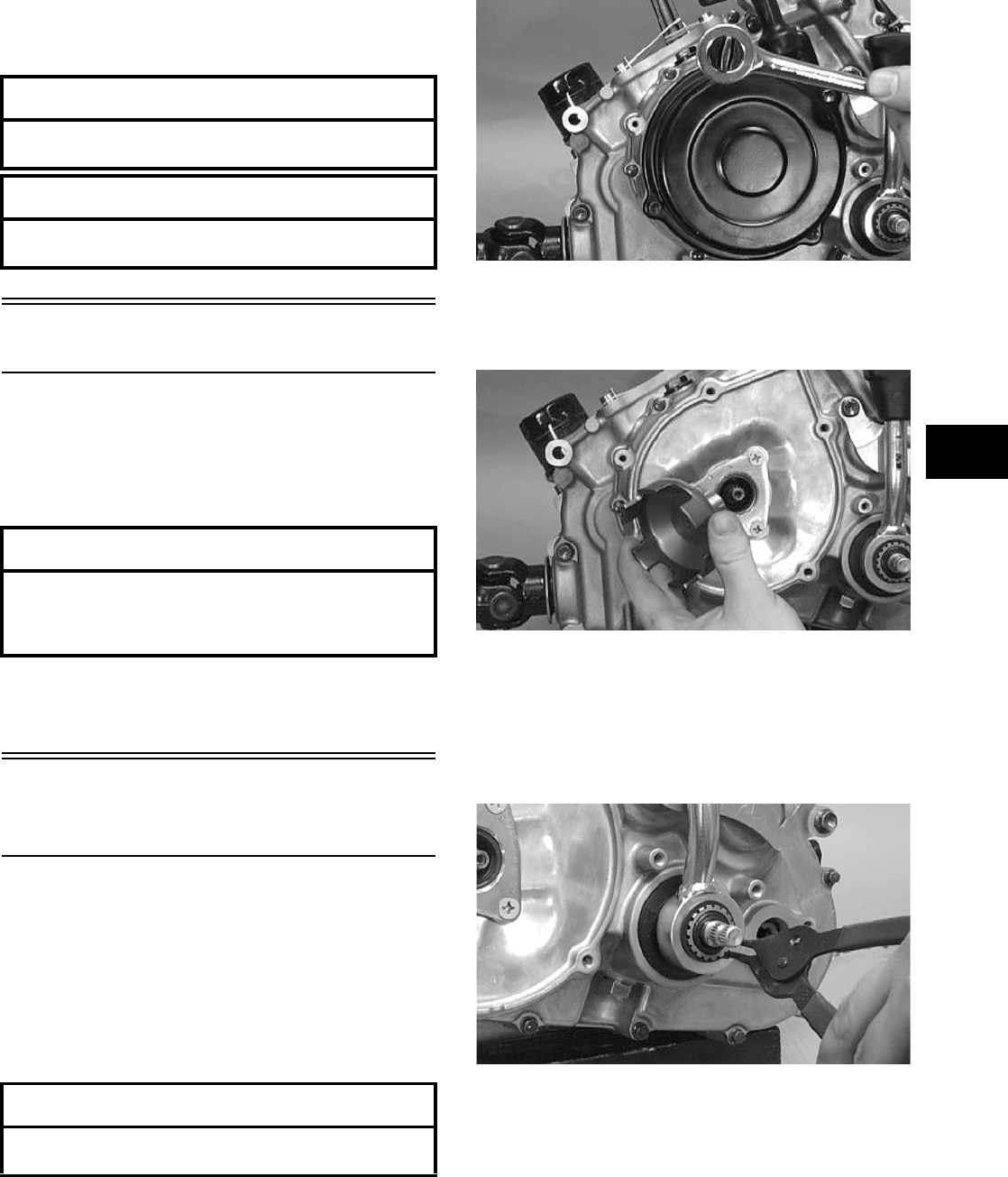
3-193
3
B. Remove each ring by working it toward the
dome of the piston while rotating it out of the
groove.
Left-Side Components
NOTE: For efficiency, it is preferable to remove
and disassemble only those components which
need to be addressed and to service only those
components. The technician should use discretion
and sound judgment.
NOTE: The engine/transmission does not have
to be removed from the frame for this procedure.
Removing Left-Side
Components
A. Recoil Starter
B. Hi/Low Shifter Assembly
C. Speed Sensor Housing
D. Cover
1. Remove the cap screws securing the recoil
starter assembly to the left-side cover; then
remove the recoil starter.
CC039D
2. Remove the flange nut securing the starter cup
to the crankshaft; then remove the starter cup.
Account for the O-ring inside the cup.
CC041D
3. Put the shift lever into the hi-range position and
remove the circlip from the hi/low range shift
shaft; then remove the shift lever.
NOTE: It will be necessary to lift slightly on the
shift lever to remove it from the shaft and plate.
CC044D
AT THIS POINT
To service piston, see Servicing Top-Side
Components sub-section.
AT THIS POINT
To service center crankcase components only,
proceed to Removing Left-Side Components.
AT THIS POINT
To service any one specific component, only
limited disassembly of components may be
necessary. Note the AT THIS POINT information in
each sub-section.
AT THIS POINT
To service the recoil starter, see Servicing
Left-Side Components sub-section.
FOR ARCTIC CAT ATV DISCOUNT PARTS CALL 606-678-9623 OR 606-561-4983
www.mymowerparts.com
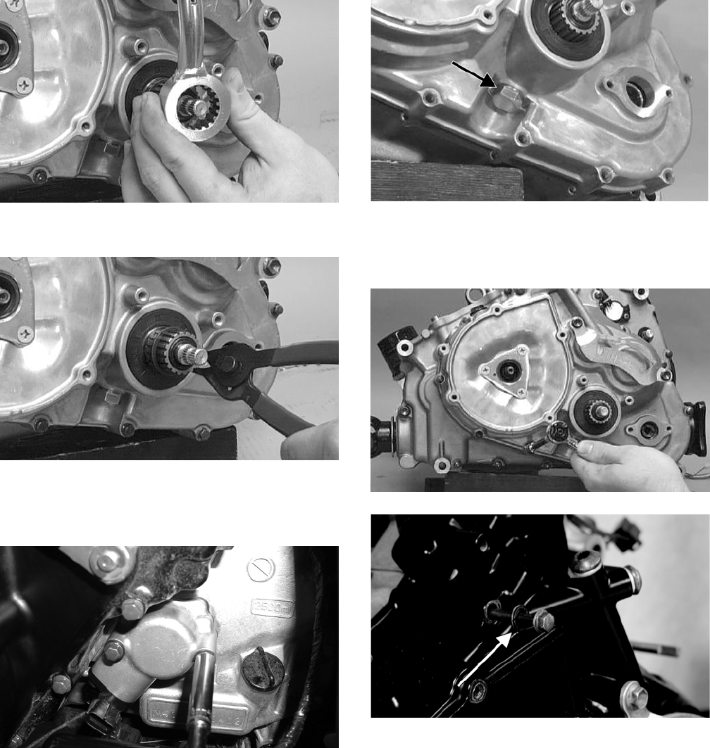
3-194
CC045D
4. Remove the inside circlip.
CC046D
5. Remove the two cap screws securing the speed
sensor housing; then remove the housing.
Account for the gasket.
CD069
6. Remove the shift stop housing assembly from
beneath the shift shaft housing. Account for the
stopper and spring.
CC054D
7. Remove the cap screws securing the left-side
cover to the crankcase and note the location of
the long cap screw with rubber washer.
CC047D
CF037A
8. Using Side Case Puller (p/n 0644-262), remove
the side cover. Account for a gasket, two align-
ment pins, and an idle gear limiter bushing.
NOTE: Inspect the inside of the left-side cover
for the four shaft washers that may have come off
with the cover. The three gear shaft washers are
identical and interchangeable. The shift shaft
washer is a larger diameter. Keep the washers with
their respective shafts for installing purposes.
FOR ARCTIC CAT ATV DISCOUNT PARTS CALL 606-678-9623 OR 606-561-4983
www.mymowerparts.com
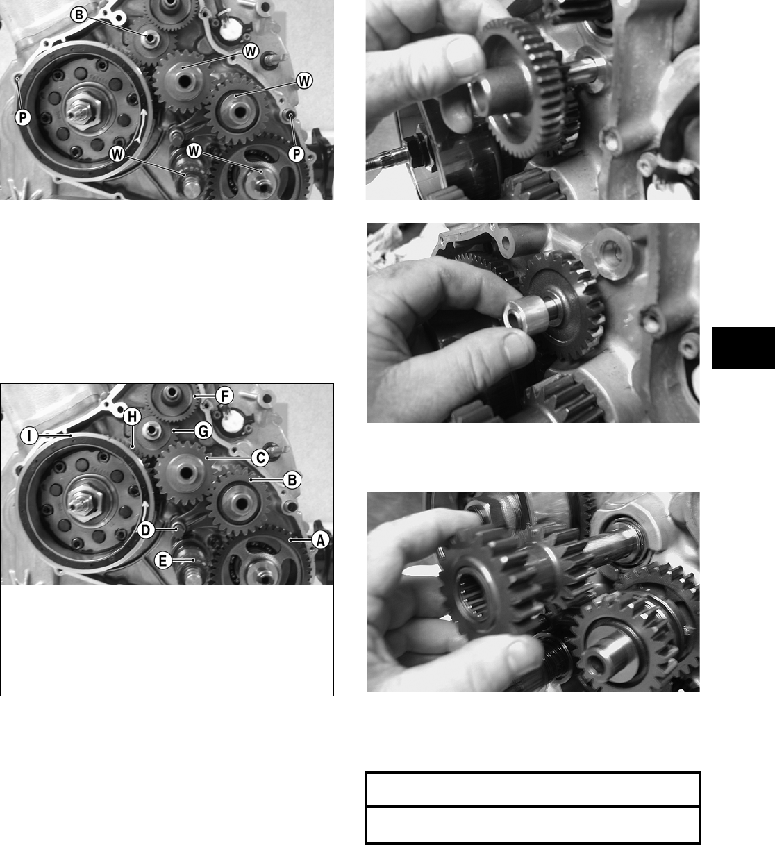
3-195
3
CD134A
E. Rotor/Flywheel
F. Idle Gear Assembly
NOTE: Steps 1-8 in the preceding sub-section
must precede this procedure.
NOTE: For steps 9-18, refer to illustration
CD134B.
CD134B
NOTE: To aid in installing, it is recommended
that the assemblies are kept together and IN
ORDER.
9. Remove the starter gear assembly (F) from the
crankcase; then remove the starter idler gear (G)
and spacer.
CD136
CD138
10. Remove the idle gear (C), washer, and spacer
from the countershaft.
CD141
11. Remove the #2 drive gear (B), washer, and the
select sliding dog gear from the driveshaft.
Account for a bushing and a washer.
12. Remove the shift fork shaft (D) from the crank-
case boss; then remove the shift fork from the
shaft. Remove the shift shaft assembly (E) from
the fixed shaft. Account for the left shaft washer.
KEY
A. Output Shaft with Driven
Gear
B. Drive Gears #1 & #2
C. Idle Gear
D. Shift Fork with Shaft
E. Shift Shaft Assembly
F. Starter Gear Assembly
G. Starter Idler Gear
H. Starter Clutch Gear
Assembly
I. Rotor/Flywheel
AT THIS POINT
To service shift fork, see Servicing Left-Side
Components sub-section.
FOR ARCTIC CAT ATV DISCOUNT PARTS CALL 606-678-9623 OR 606-561-4983
www.mymowerparts.com
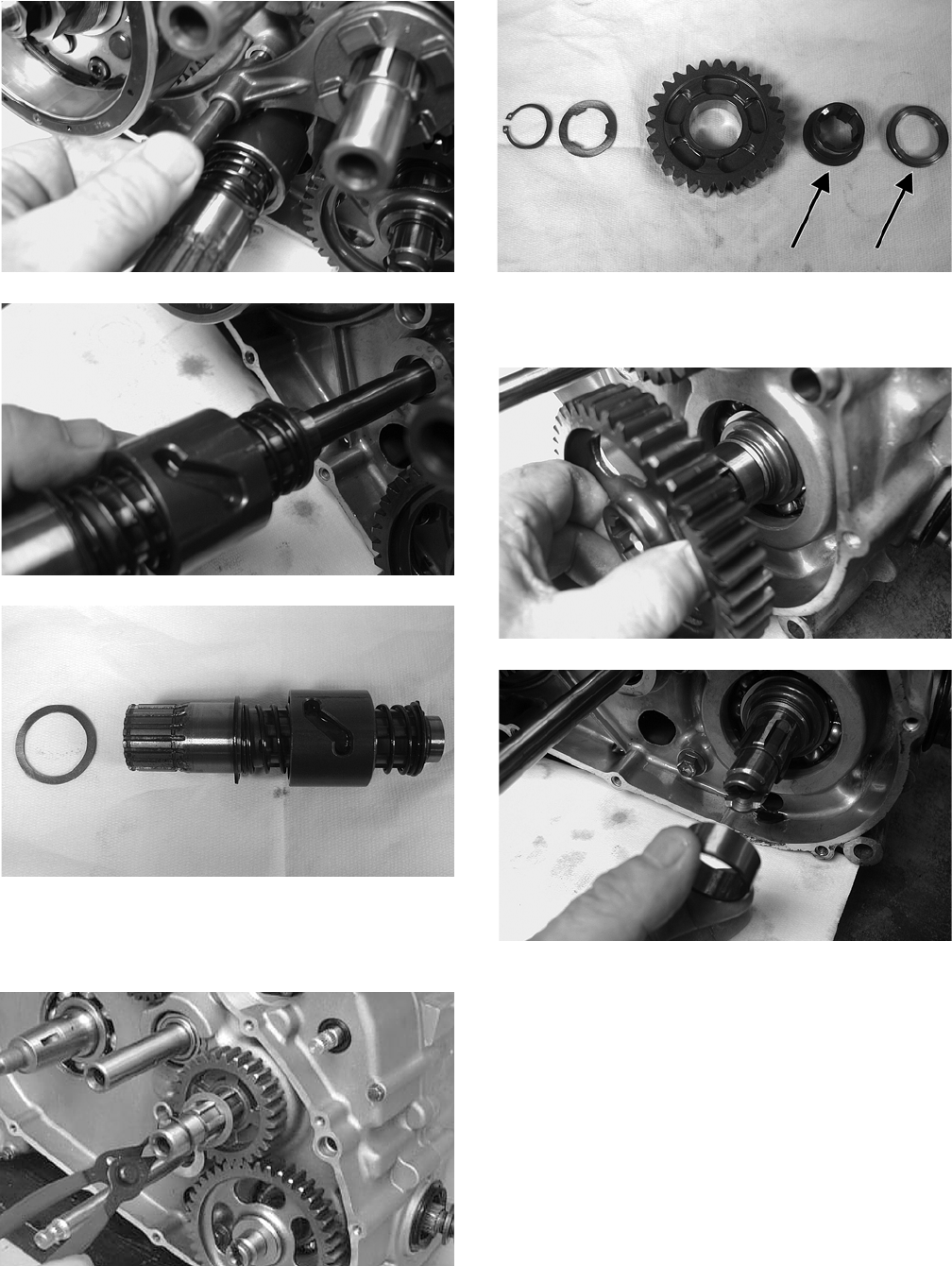
3-196
CD146
CD147
CD152
13. Remove the circlip and washer from the drive-
shaft; then remove the #1 drive gear (B).
Account for a splined bushing and a spacer.
CC059D
CD154A
14. Remove the washer and driven gear (A) from
the output shaft; then account for the bushing.
CD149
CD150
15. Remove the Allen-head screws securing the
shift-indicator sending unit; then remove the
sending unit. Account for an O-ring, two con-
tacts, and two springs.
FOR ARCTIC CAT ATV DISCOUNT PARTS CALL 606-678-9623 OR 606-561-4983
www.mymowerparts.com
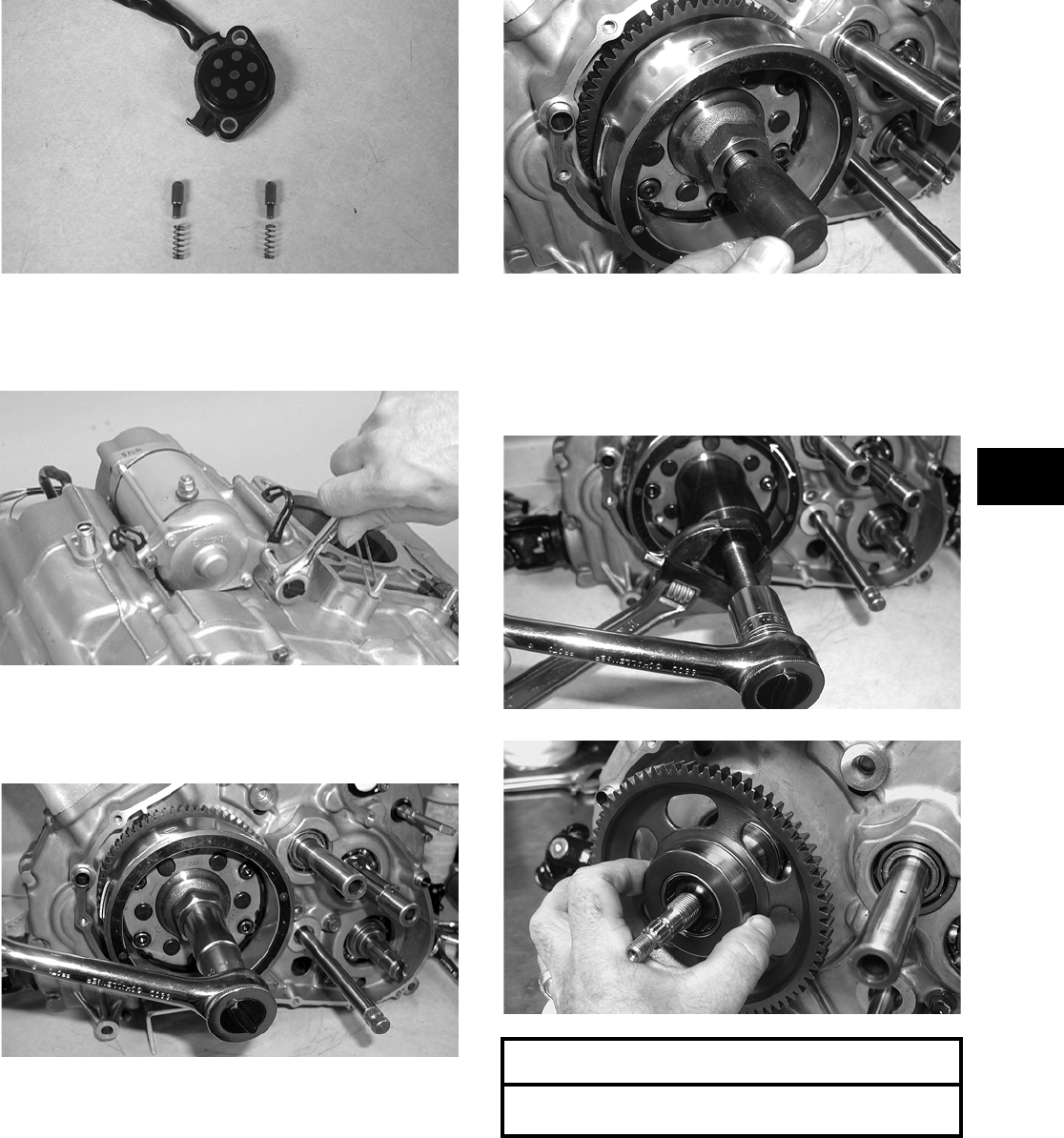
3-197
3
CD159
16. Remove the two cap screws securing the starter
to the crankcase; then remove the starter.
Account for the wiring forms.
CC065D
17. Remove the nut securing the rotor/flywheel (I)
to the crankshaft; then install the magneto rotor
remover adapter.
CD562
CD549
18. Using Magneto Rotor Remover (p/n 0444-075),
remove the rotor/flywheel assembly from the
crankshaft. Account for the key; then remove
the starter clutch gear assembly (H) and thrust
washer.
CD550
CD155
AT THIS POINT
To service center crankcase components only,
proceed to Removing Right-Side Components.
FOR ARCTIC CAT ATV DISCOUNT PARTS CALL 606-678-9623 OR 606-561-4983
www.mymowerparts.com
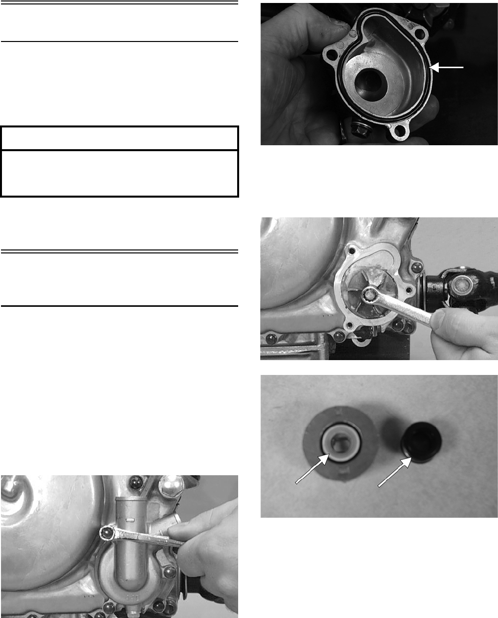
3-198
Right-Side Components
NOTE: For efficiency, it is preferable to remove
and disassemble only those components which
need to be addressed and to service only those
components. The technician should use discretion
and sound judgment.
NOTE: The engine/transmission does not have
to be removed from the frame for this procedure.
Removing Right-Side
Components
A. Oil Filter
B. Water Pump
1. Remove the clamp securing the coolant hose to
the water pump; then remove the hose.
2. Using the adjustable Oil Filter Wrench (p/n
0644-389), remove the oil filter.
3. Remove the three cap screws securing the water
pump cover to the right-side cover; then remove
the water pump cover. Account for the O-ring.
CC027D
CF066A
4. Remove the cap screw securing the impeller to
the impeller shaft; then remove the impeller.
Account for the rubber retainer and porcelain
seal.
CC029D
CD163A
5. Remove the fifteen cap screws securing the
right-side cover to the crankcase. Remove the
cover. Note the location of the long cap screw
and rubber washer. Account for the gasket and
for two alignment pins.
AT THIS POINT
To service any one specific component, only
limited disassembly of components may be
necessary. Note the AT THIS POINT information in
each sub-section.
FOR ARCTIC CAT ATV DISCOUNT PARTS CALL 606-678-9623 OR 606-561-4983
www.mymowerparts.com
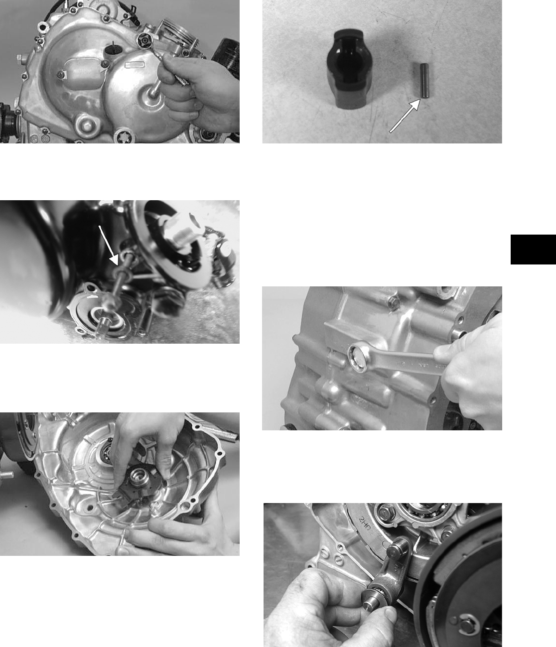
3-199
3
CC034D
NOTE: The water pump housing does not have
to be removed when removing the right-side cover.
CD164A
NOTE: When removing the right-side cover,
account for the release roller guide that it does not
fall and cause damage.
CC070D
6. Remove the water pump drive joint from the
water pump shaft. Account for the pin.
CD168A
C. Primary Drive Clutch Shoe
D. Primary Driven Clutch
E. Primary Drive Clutch Housing
NOTE: Steps 1-6 in the preceding sub-section
must precede this procedure.
7. Remove the reverse cam stopper housing and
gasket and account for a stopper and spring.
CC069D
8. Remove the clutch release arm and washer; then
in a crisscross pattern, remove the four cap
screws securing the clutch release roller assem-
bly.
CD171
FOR ARCTIC CAT ATV DISCOUNT PARTS CALL 606-678-9623 OR 606-561-4983
www.mymowerparts.com
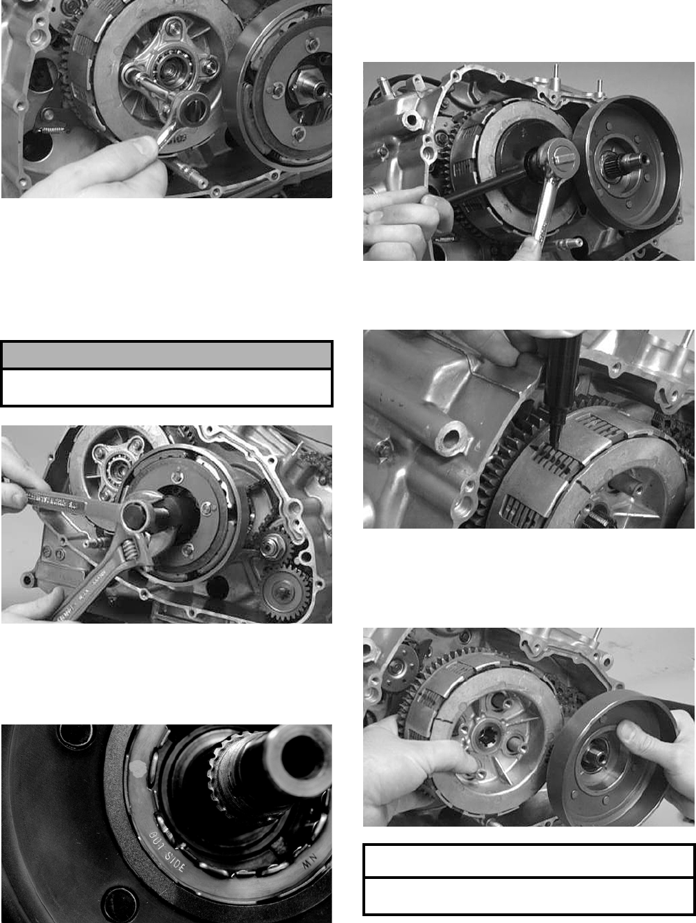
3-200
CC074D
9. Remove the release plate. Account for four
springs.
10. Remove the primary drive clutch-shoe nut
(left-hand threads) and washer from the drive-
shaft; then using a primary clutch shoe remover,
remove the clutch shoe.
CC072D
11. Remove the primary drive one-way clutch from
the primary drive clutch housing. Note the word
OUTSIDE stamped on the clutch for installing
purposes.
CF043
12. Using the Clutch Sleeve Hub Holder (p/n
0444-007) to hold the clutch sleeve hub, remove
the nut and washer.
CC076D
13. Scribe a line across the primary driven clutch
assembly to aid in assembling.
CC077D
14. Simultaneously, remove the primary driven
clutch assembly and primary drive clutch hous-
ing from their respective shafts. Account for the
sleeve and washers.
CC078D
! CAUTION
Care must be taken when removing the nut; it has
“left-hand” threads.
AT THIS POINT
To service clutch components, see Servicing
Right-Side Components sub-section.
FOR ARCTIC CAT ATV DISCOUNT PARTS CALL 606-678-9623 OR 606-561-4983
www.mymowerparts.com
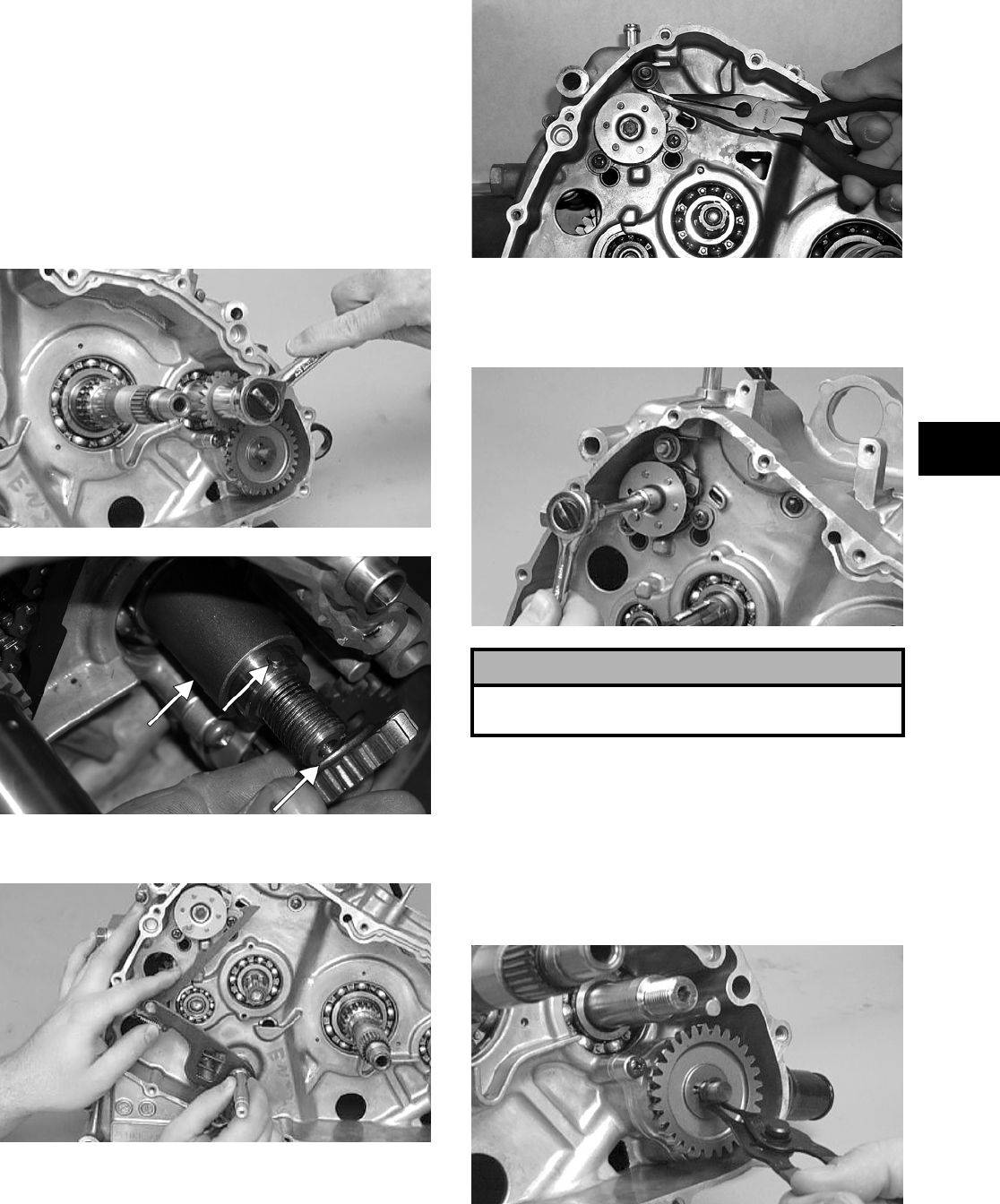
3-201
3
F. Gear Shift Cam Plate/Guide
G. Oil Pump/Oil Strainer
NOTE: Steps 1-14 in the preceding sub-sections
must precede this procedure.
15. Remove the cam chain from the crankcase.
16. Remove the nut and washer securing the oil
pump drive gear to the crank balancer shaft;
then remove the gear and account for the pin and
the spacer.
CC080D
CF070A
17. Remove the gear shift shaft from the crankcase.
CC085D
18. Release the tension from the gear shift cam stop-
per arm spring.
CC086D
19. Remove the cap screw securing the gear shift
cam plate and guide to the gear shift cam; then
remove the cam plate and guide.
CC164D
NOTE: For general servicing, it is advisable to
disassemble, clean, and inspect the oil pump. If
any wear or damage is suspected, replace the oil
pump.
20. Remove the circlip securing the oil pump driven
gear; then remove the gear. Account for the pin
and the washer.
CC088D
! CAUTION
If servicing of the engine/transmission is due to a
lubrication-related problem, replace the oil pump.
FOR ARCTIC CAT ATV DISCOUNT PARTS CALL 606-678-9623 OR 606-561-4983
www.mymowerparts.com
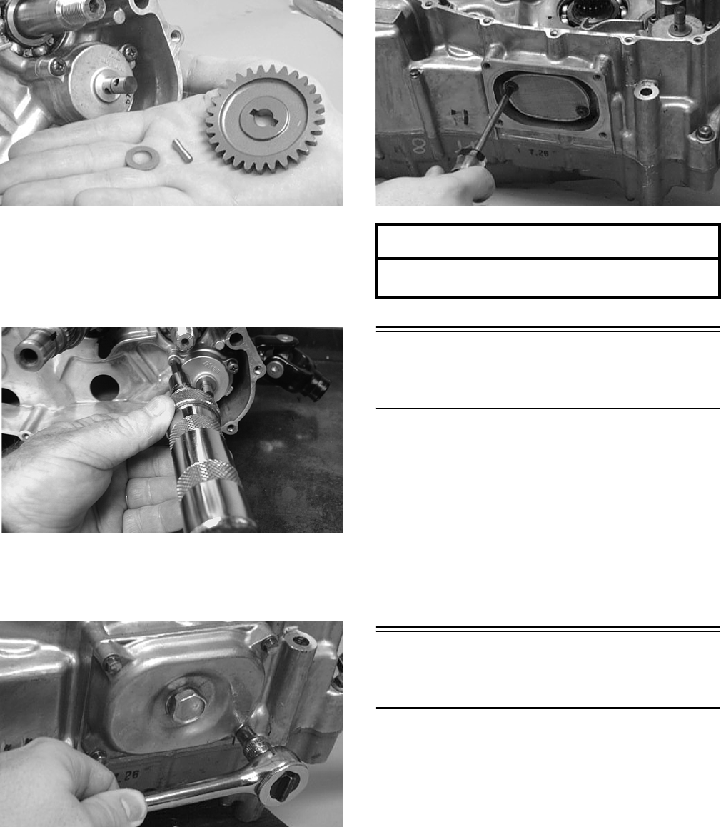
3-202
CC089D
21. Remove the three Phillips-head screws securing
the oil pump; then remove the oil pump.
NOTE: It may be necessary to use an impact
driver to loosen the screws.
CD190
22. Remove the cap screws securing the oil strainer
cap; then remove the cap. Account for the
O-ring.
CC091D
23. Remove the two Phillips-head cap screws secur-
ing the strainer.
CC163D
Center Crankcase
Components
NOTE: This procedure cannot be done with the
engine/transmission in the frame. Complete
Removing procedures for Top-Side, Left-Side, and
Right-Side must precede this procedure.
NOTE: For efficiency, it is preferable to remove
and disassemble only those components which
need to be addressed and to service only those
components. The technician should use discretion
and sound judgment.
Separating Crankcase
Halves
1. Remove the five right-side 6 mm cap screws
(one from inside the case) securing the crank-
case halves. Note the location of the differ-
ent-lengthed cap screws.
AT THIS POINT
To service center crankcase components only,
proceed to Separating Crankcase Halves.
FOR ARCTIC CAT ATV DISCOUNT PARTS CALL 606-678-9623 OR 606-561-4983
www.mymowerparts.com
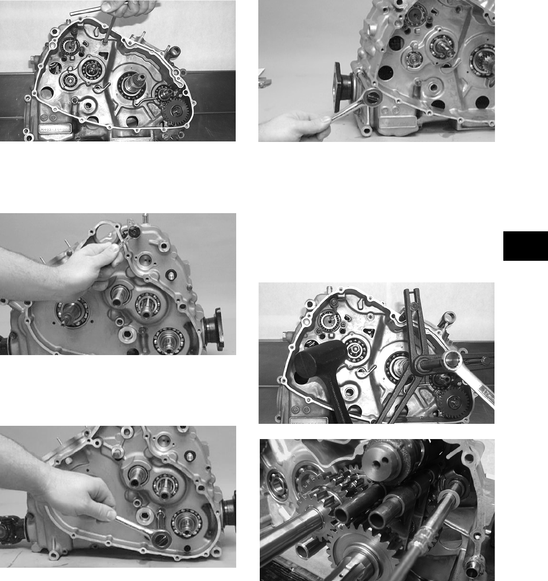
3-203
3
CC530D
2. Remove the seven left-side 6 mm cap screws
securing the crankcase halves. Note the location
of the wiring form. Note the location of the dif-
ferent-lengthed cap screws.
CC096D
3. Remove the three left-side 8 mm cap screws
(two from inside the case) securing the crank-
case halves. Note the location of the differ-
ent-lengthed cap screws.
CC097D
4. Remove the three right-side 8 mm cap screws
securing the crankcase halves.
CC098D
5. Using the Crankcase Separator/Crankshaft
Remover (p/n 0444-009) and tapping lightly
with a rubber mallet, separate the crankcase
halves. Account for two alignment pins, an
O-ring, and a washer.
NOTE: To keep the shaft/gear assemblies intact
for identification, tap the shafts toward the
left-side crankcase half when separating the
halves.
CC099D
CD227
FOR ARCTIC CAT ATV DISCOUNT PARTS CALL 606-678-9623 OR 606-561-4983
www.mymowerparts.com
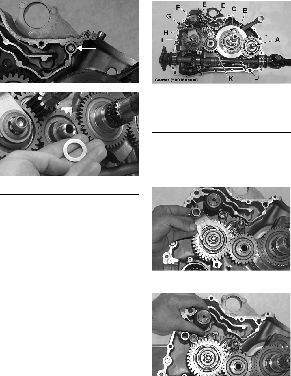
3-204
CF078A
CC102D
Disassembling
Crankcase Half
NOTE: For steps 1-10, refer to illustration
CC803C.
NOTE: To aid in assembling, it is recommended
that the assemblies are kept together and IN
ORDER.
CC803C
1. Remove the two shift shafts (E and H).
2. Remove the reverse shift cam (G) and spacer.
3. Disengage four forks from the gear shift cam
(F); then remove the reverse shifter fork.
CC105D
4. Remove the gear shift cam (F).
CC106D
5. Remove the three remaining forks noting their
positions for assembling purposes.
KEY
A. Crank Balancer Assembly
B. Crankshaft
C. Balancer Drive Gear with
Pin
D. Countershaft Assembly
E. Shift Shaft with Fork
F. Gear Shift Cam
G. Reverse Shift Cam
H. Shift Shaft with Three
Forks
I. Driveshaft Assembly
J. Output Shaft
K. Reverse Idle Gear
FOR ARCTIC CAT ATV DISCOUNT PARTS CALL 606-678-9623 OR 606-561-4983
www.mymowerparts.com
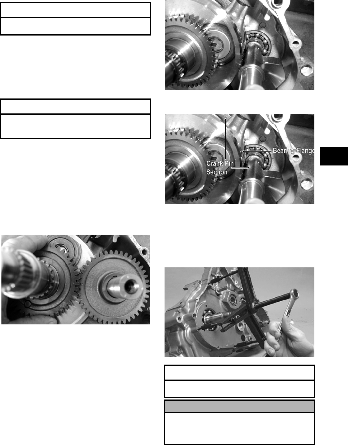
3-205
3
6. Remove the reverse idle gear (K) w/shaft.
Account for the bushing, two washers, and the
circlip.
7. Simultaneously, remove the driveshaft assembly
(I) and countershaft assembly (D). Account for
the washer on the countershaft.
NOTE: For efficiency, if the driveshaft and/or
countershaft are not being serviced, it is prefera-
ble to leave them assembled. The technician
should use discretion and sound judgment.
8. Remove the front output shaft (J) and rear shaft
assemblies. Account for the bearing C-ring.
NOTE: Note the alignment marks on the crank
balancer driven gear and balancer drive gear to aid
in assembly.
CD826
9. Remove the driven gear from the crank balancer
assembly (A). Account for a key.
CD832
10. Remove the crank balancer assembly (A).
CD832B
NOTE: There is a flat spot on the crank balancer
to allow clearance past the crankshaft.
11. Using the Crankcase Separator/Crankshaft
Remover (p/n 0444-009), push the crankshaft
assembly out of the crankcase.
CC115D
AT THIS POINT
To service gear shift forks, see Servicing Center
Crankcase Components sub-section.
AT THIS POINT
To service the driveshaft and/or countershaft, see
Servicing Center Crankcase Components sub-sec-
tion.
AT THIS POINT
To service crankshaft assembly, see Servicing Cen-
ter Crankcase Components sub-section.
! CAUTION
Do not remove the remaining output shaft assembly
unless absolutely necessary. If the shaft is removed,
the shaft nut must be replaced with a new one and
the shaft must be re-shimmed.
FOR ARCTIC CAT ATV DISCOUNT PARTS CALL 606-678-9623 OR 606-561-4983
www.mymowerparts.com
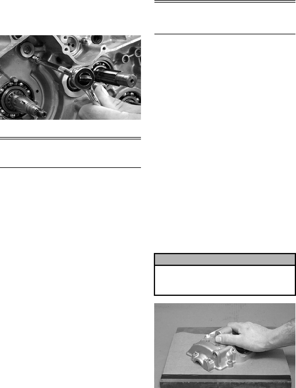
3-206
12. To remove the output shaft and gear, remove the
nut, slide the gear off the shaft (account for a
shim or shims), and drive the shaft out with a
plastic mallet (account for a shim or shims).
CC482D
Table of Contents
(Servicing Components)
NOTE: Critical engine/transmission specifica-
tions are located at the beginning of this section.
Servicing Top-Side Components……………………. 3-206
Valve Assembly…….…………….…………….……… 3-206
Piston Assembly ………..…………….…………….… 3-209
Cylinder/Cylinder Head Assembly ………………. 3-211
Servicing Left-Side Components ..…………….…… 3-214
Recoil Starter…………….…………….…………….… 3-214
Measuring Shift Fork (Thickness) …………..…… 3-217
Measuring Shift Fork Groove (Width) ………….. 3-218
Measuring Shift Fork To Groove
(Side Clearance)………..…………….……………. 3-218
Servicing Right-Side Components ……………….… 3-218
Primary Clutch Assembly…………..………….…… 3-218
Inspecting Oil Pump……………….…………….…… 3-221
Servicing Center Crankcase Components………. 3-221
Secondary Gears…….………….…………….……… 3-221
Crankshaft Assembly.…………….…………….…… 3-222
Driveshaft…………….………………………..………… 3-224
Countershaft …………..…………….…………….…… 3-230
Servicing Top-Side
Components
NOTE: Whenever a part is worn excessively,
cracked, or damaged in any way, replacement is
necessary.
VALVE ASSEMBLY
When servicing valve assembly, inspect valve seats,
valve stems, valve faces, and valve stem ends for
pits, burn marks, or other signs of abnormal wear.
NOTE: Whenever a valve is out of tolerance, it
must be replaced.
Cleaning/Inspecting Valve Cover
NOTE: If the valve cover cannot be trued, the cyl-
inder head assembly must be replaced.
1. Wash the valve cover in parts-cleaning solvent.
2. Place the valve cover on the Surface Plate (p/n
0644-016) covered with #400 grit wet-or-dry
sandpaper. Using light pressure, move the valve
cover in a figure eight motion. Inspect the seal-
ing surface for any indication of high spots. A
high spot can be noted by a bright metallic fin-
ish. Correct any high spots before assembly by
continuing to move the valve cover in a figure
eight motion until a uniform bright metallic fin-
ish is attained.
CC130D
! CAUTION
Do not remove an excessive amount of the sealing
surface or damage to the camshaft will result.
Always check camshaft clearance when resurfacing
the valve cover.
FOR ARCTIC CAT ATV DISCOUNT PARTS CALL 606-678-9623 OR 606-561-4983
www.mymowerparts.com
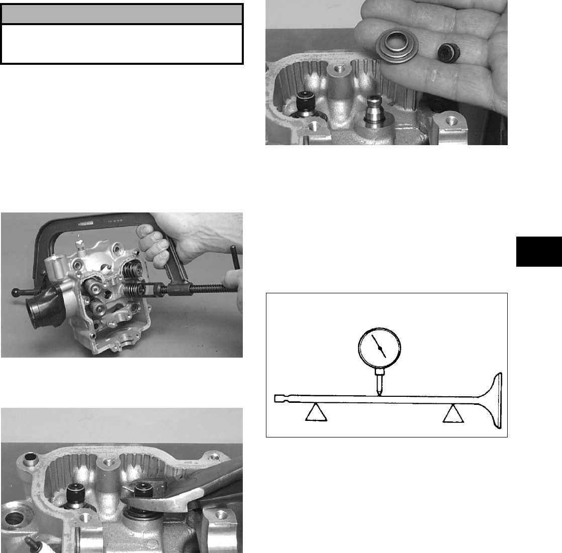
3-207
3
Removing Valves
NOTE: Keep all valves and valve components as
a set. Note the original location of each valve set
for use during installation. Return each valve set to
its original location during installation.
1. Using a valve spring compressor, compress the
valve springs and remove the valve cotters.
Account for an upper spring retainer.
CC132D
2. Remove the valve seal and the lower remaining
spring seat. Discard the valve seal.
CC134D
CC136D
NOTE: The valve seals must be replaced.
3. Remove the valve springs; then invert the cylin-
der head and remove the valves.
Measuring Valve Stem Runout
1. Support each valve stem end with the V Blocks
(p/n 0644-022); then check the valve stem
runout using a dial indicator.
ATV-1082
2. Maximum runout must not exceed specifica-
tions.
Measuring Valve Stem
Outside Diameter
1. Using a micrometer, measure the valve stem
outside diameter.
2. Acceptable diameter range (intake valve) must
be within specifications.
3. Acceptable diameter range (exhaust valve) must
be within specifications.
Measuring Valve Face/Seat Width
1. Using a micrometer, measure the width of the
valve face.
! CAUTION
Water or parts-cleaning solvent must be used in
conjunction with the wet-or-dry sandpaper or dam-
age to the sealing surface may result.
FOR ARCTIC CAT ATV DISCOUNT PARTS CALL 606-678-9623 OR 606-561-4983
www.mymowerparts.com
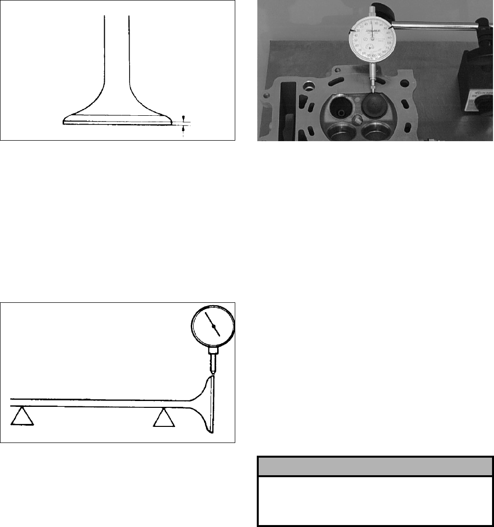
3-208
ATV-1004
2. Acceptable width range must be within specifi-
cations.
Measuring Valve Face Radial
Runout
1. Mount a dial indicator on the surface plate; then
place the valve stem on a set of V blocks.
2. Position the dial indicator contact point on the
outside edge of the valve face; then zero the
indicator.
ATV1082A
3. Rotate the valve in the V blocks.
4. Maximum runout must not exceed specifica-
tions.
Measuring Valve Guide/Valve Stem
Deflection (Wobble Method)
1. Mount a dial indicator and base on the surface
plate; then place the cylinder head on the surface
plate.
2. Install the valve into the cylinder head; then
position the dial indicator contact point against
the outside edge of the valve face. Zero the indi-
cator.
CC131D
3. Push the valve from side to side; then from top
to bottom.
4. Maximum “wobble” deflection must not exceed
specifications.
Measuring Valve Guide
(Inside Diameter)
1. Insert a snap gauge 1/2 way down into each
valve guide bore; then remove the gauge and
measure it with a micrometer.
2. Acceptable inside diameter range must be
within specifications.
3. If a valve guide is out of tolerance, it must be
replaced.
Servicing Valves/Valve
Guides/Valve Seats
If valves, valve guides, or valve seats require servic-
ing or replacement, Arctic Cat recommends that the
components be taken to a qualified machine shop
for servicing.
Measuring Rocker Arm
(Inside Diameter)
1. Using a dial calipers, measure the inside diame-
ter of the rocker arm.
2. Acceptable inside diameter range must be
within specifications.
Measuring Rocker Arm Shaft
(Outside Diameter)
1. Using a micrometer, measure the outside diame-
ter of the rocker arm shaft.
! CAUTION
If valves are discolored or pitted or if the seating
surface is worn, the valve must be replaced. Do not
attempt to grind the valves or severe engine damage
may occur.
FOR ARCTIC CAT ATV DISCOUNT PARTS CALL 606-678-9623 OR 606-561-4983
www.mymowerparts.com
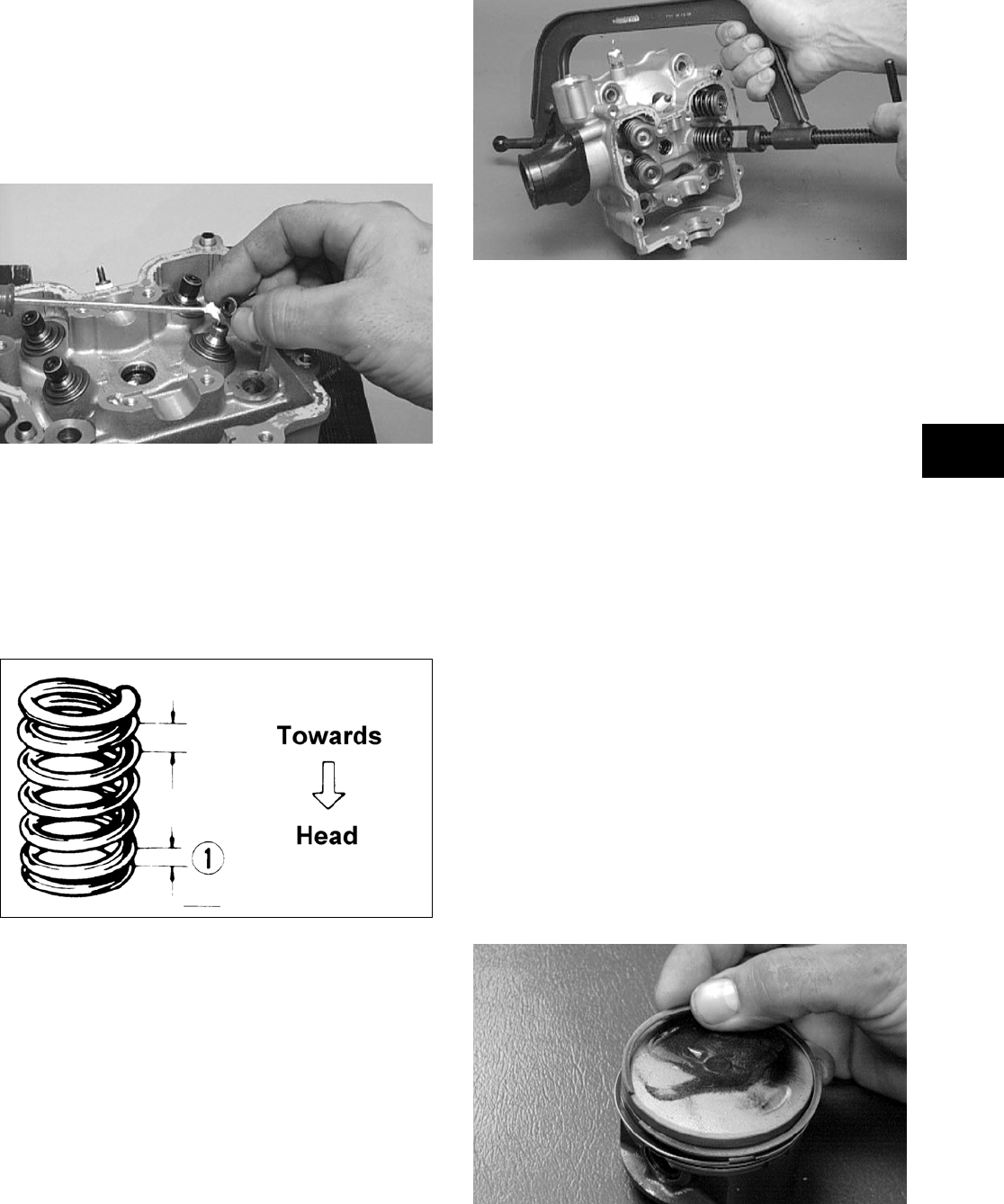
3-209
3
2. Acceptable outside diameter range must be
within specifications.
Installing Valves
1. Apply grease to the inside surface of the valve
seals; then place a lower spring seat and valve
guide seal over each valve guide.
CC144D
2. Insert each valve into its original valve location.
3. Install the valve springs with the painted end of
the spring facing away from the cylinder head.
NOTE: If the paint is not visible, install the ends
of the springs with the closest wound coils toward
the head.
ATV-1011A
4. Place a spring retainer over the valve springs;
then using the valve spring compressor, com-
press the valve springs and install the valve cot-
ters.
CC132D
PISTON ASSEMBLY
NOTE: Whenever a piston, rings, or pin are out
of tolerance, they must be replaced.
Cleaning/Inspecting Piston
1. Using a non-metallic carbon removal tool,
remove any carbon buildup from the dome of
the piston.
2. Inspect the piston for cracks in the piston pin,
dome, and skirt areas.
3. Inspect the piston for seizure marks or scuffing.
Repair with #400 grit wet-or-dry sandpaper and
water or honing oil.
NOTE: If scuffing or seizure marks are too deep
to correct with the sandpaper, replace the piston.
4. Inspect the perimeter of each piston for signs of
excessive “blowby.” Excessive “blowby” indi-
cates worn piston rings or an out-of-round cylin-
der.
Removing Piston Rings
1. Starting with the top ring, slide one end of the
ring out of the ring-groove.
CC400D
2. Remove each ring by working it toward the
dome of the piston while rotating it out of the
groove.
FOR ARCTIC CAT ATV DISCOUNT PARTS CALL 606-678-9623 OR 606-561-4983
www.mymowerparts.com
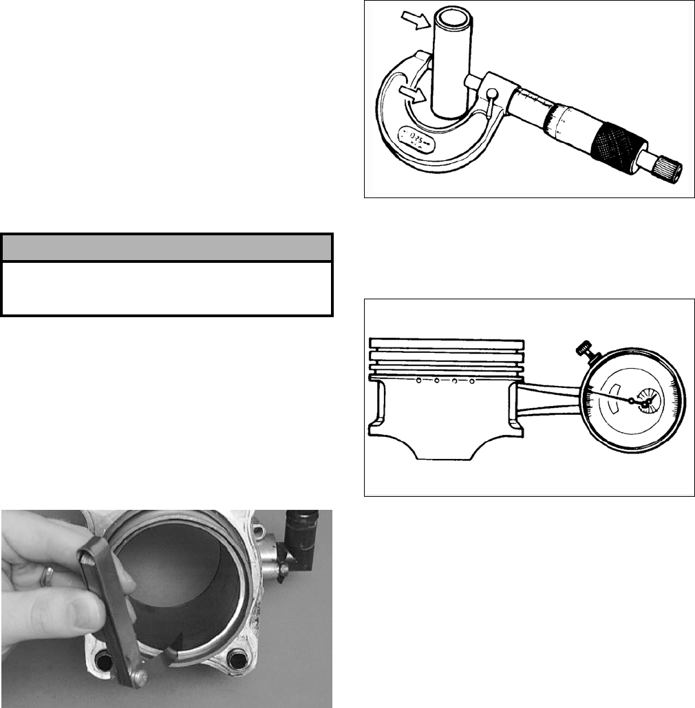
3-210
NOTE: If the existing rings will not be replaced
with new ones, note the location of each ring for
proper installation. When installing new rings,
install as a complete set only.
Cleaning/Inspecting Piston Rings
1. Take an old piston ring and snap it into two
pieces; then grind the end of the old ring to a 45°
angle and to a sharp edge.
2. Using the sharpened ring as a tool, clean carbon
from the ring-grooves. Be sure to position the
ring with its tapered side up.
Measuring Piston-Ring End Gap
(Installed)
1. Place each piston ring in the wear portion of the
cylinder. Use the piston to position each ring
squarely in the cylinder.
2. Using a feeler gauge, measure each piston-ring
end gap. Acceptable ring end gap must be
within specifications.
CC280D
Measuring Piston Pin (Outside
Diameter) and Piston-Pin Bore
1. Measure the piston pin outside diameter at each
end and in the center. If measurement is not
within specifications, the piston pin must be
replaced.
ATV-1070
2. Insert an inside dial indicator into the piston-pin
bore. The diameter must not exceed specifica-
tions. Take two measurements to ensure accu-
racy.
ATV-1069
Measuring Piston Skirt/
Cylinder Clearance
1. Measure the cylinder front to back in six places.
2. Measure the corresponding piston diameter at a
point 15 mm (0.6 in.) above the piston skirt at a
right angle to the piston-pin bore. Subtract this
measurement from the measurement in step 1.
The difference (clearance) must be within speci-
fications.
Installing Piston Rings
1. Install ring expander (4) in the bottom groove of
the piston; then install the thin oil rings (3) over
the expander making sure the expander ends do
not overlap. Stagger the end gaps of the upper
and lower thin oil rings according to the illustra-
tion.
NOTE: Note the direction of the exhaust side of
the piston (5) for correct ring end gap orientation.
! CAUTION
Improper cleaning of the ring-grooves by the use of
the wrong type of ring-groove cleaner will result in
severe damage to the piston.
FOR ARCTIC CAT ATV DISCOUNT PARTS CALL 606-678-9623 OR 606-561-4983
www.mymowerparts.com
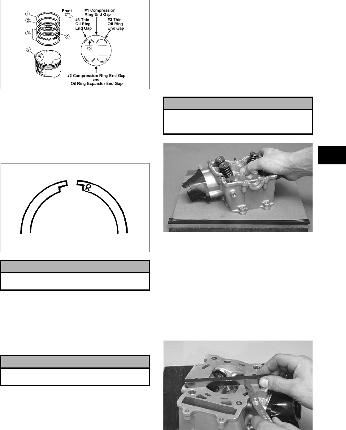
3-211
3
ATV-1085B
2. Install the compression rings (1 and 2) so the let-
ter on the top surface of each ring faces the
dome of the piston. Rotate the rings until the
ring end gaps are on directly opposite sides of
the piston (see illustration).
NOTE: The chrome (silver) ring should be
installed in the top position.
726-306A
CYLINDER/CYLINDER HEAD
ASSEMBLY
NOTE: If the cylinder/cylinder head assembly
cannot be trued, they must be replaced.
Cleaning/Inspecting Cylinder Head
1. Using a non-metallic carbon removal tool,
remove any carbon buildup from the combus-
tion chamber being careful not to nick, scrape,
or damage the combustion chamber or the seal-
ing surface.
2. Inspect the spark plug hole for any damaged
threads. Repair damaged threads using a
“heli-coil” insert.
3. Place the cylinder head on the surface plate cov-
ered with #400 grit wet-or-dry sandpaper. Using
light pressure, move the cylinder head in a fig-
ure eight motion. Inspect the sealing surface for
any indication of high spots. A high spot can be
noted by a bright metallic finish. Correct any
high spots before assembly by continuing to
move the cylinder head in a figure eight motion
until a uniform bright metallic finish is attained.
CC128D
Measuring Cylinder Head
Distortion
1. Remove any carbon buildup in the combustion
chamber.
2. Lay a straightedge across the cylinder head; then
using a feeler gauge, check the distortion factor
between the head and the straightedge.
3. Maximum distortion must not exceed specifica-
tions.
CC141D
! CAUTION
Incorrect installation of the piston rings will result in
engine damage.
! CAUTION
The cylinder head studs must be removed for this
procedure.
! CAUTION
Water or parts-cleaning solvent must be used in
conjunction with the wet-or-dry sandpaper or dam-
age to the sealing surface may result.
FOR ARCTIC CAT ATV DISCOUNT PARTS CALL 606-678-9623 OR 606-561-4983
www.mymowerparts.com
3-212
Cleaning/Inspecting Cylinder
1. Wash the cylinder in parts-cleaning solvent.
2. Inspect the cylinder for pitting, scoring, scuff-
ing, warpage, and corrosion. If marks are found,
repair the surface using a cylinder hone (see
Honing Cylinder in this sub-section).
3. Place the cylinder on the surface plate covered
with #400 grit wet-or-dry sandpaper. Using light
pressure, move the cylinder in a figure eight
motion. Inspect the sealing surface for any indi-
cation of high spots. A high spot can be noted by
a bright metallic finish. Correct any high spots
before assembly by continuing to move the cyl-
inder in a figure eight motion until a uniform
bright metallic finish is attained.
CC129D
Inspecting Cam Chain Guide
1. Inspect cam chain guide for cuts, tears, breaks,
or chips.
2. If the chain guide is damaged, it must be
replaced.
Honing Cylinder
1. Using a slide gauge and a dial indicator or a
snap gauge, measure the cylinder bore diameter
in three locations from top to bottom and again
from top to bottom at 90° from the first mea-
surements for a total of six measurements. The
trueness (out-of-roundness) is the difference
between the highest and lowest reading. Maxi-
mum trueness (out-of-roundness) must not
exceed specifications.
CC127D
2. Wash the cylinder in parts-cleaning solvent.
3. Inspect the cylinder for pitting, scoring, scuff-
ing, and corrosion. If marks are found, repair the
surface using a ball hone.
NOTE: To produce the proper 60° cross-hatch
pattern, use a low RPM drill (600 RPM) at the rate
of 30 strokes per minute. If honing oil is not avail-
able, use a lightweight petroleum-based oil. Thor-
oughly clean cylinder after honing using soap and
hot water. Dry with compressed air; then immedi-
ately apply oil to the cylinder bore. If the bore is
severely damaged or gouged, replace the cylinder.
CC390D
4. If any measurement exceeds specifications,
replace the cylinder.
Measuring Camshaft Runout
NOTE: If the camshaft is out of tolerance, it must
be replaced.
1. Place the camshaft on a set of V blocks; then
position the dial indicator contact point against
the shaft and zero the indicator.
! CAUTION
Water or parts-cleaning solvent must be used in
conjunction with the wet-or-dry sandpaper or dam-
age to the sealing surface may result.
FOR ARCTIC CAT ATV DISCOUNT PARTS CALL 606-678-9623 OR 606-561-4983
www.mymowerparts.com
3-213
3
CC283D
2. Rotate the camshaft and note runout; maximum
tolerance must not exceed specifications.
Measuring Camshaft Lobe Height
1. Using a calipers, measure each cam lobe height.
ATV1013A
2. The lobe heights must not exceed minimum
specifications.
Inspecting Camshaft Bearing
Journal
1. Inspect the bearing journal for scoring, seizure
marks, or pitting.
2. If excessive scoring, seizure marks, or pitting is
found, the cylinder head assembly must be
replaced.
Measuring Camshaft to
Cylinder Head Clearance
1. Remove the adjuster screws and jam nuts.
CC005D
2. Place a strip of plasti-gauge in each of the cam-
shaft lands in the cylinder head.
3. Place the valve cover on the cylinder head and
secure with the valve cover cap screws. Tighten
securely.
NOTE: Do not rotate the camshaft when measur-
ing clearance.
4. Remove the cap screws securing the valve cover
to the cylinder; then remove the valve cover and
camshaft.
CC003D
5. Match the width of the plasti-gauge with the
chart found on the plasti-gauge packaging to
determine camshaft to cylinder head and valve
cover clearance.
CC145D
6. If clearance is excessive, measure the journals of
the camshaft.
FOR ARCTIC CAT ATV DISCOUNT PARTS CALL 606-678-9623 OR 606-561-4983
www.mymowerparts.com
3-214
CC287D
NOTE: If the journals are worn, replace the cam-
shaft; then measure the clearance again. If it is still
out of tolerance, replace the cylinder head.
Inspecting Camshaft Automatic
Decompression Spring/Unloader
Assembly
1. Inspect the spring, weights, and unloader for
damage and freedom of movement.
CF061A
NOTE: With the weight extended, the unloader
flat should be even with the camshaft journal.
CF061
NOTE: When the weight is released, the spring
should return the assembly to the “unload” posi-
tion with the unloader extending above the cam-
shaft journal.
CF060A
2. If damaged, the camshaft must be replaced.
Servicing Left-Side
Components
RECOIL STARTER
0737-034
Removing/Disassembling
1. Remove the cap screws securing the recoil
starter assembly to the left-side cover; then
remove the starter.
! WARNING
Always wear safety glasses when servicing the
recoil starter.
KEY
1. Recoil Starter
Assy
2. Reel
3. Spiral Spring
4. Ratchet Assy
5. Ratchet
6. Ratchet Guide
7. Nut
8. Rope Assy
9. Cap Screw
10. Starter Cup
11. Nut
FOR ARCTIC CAT ATV DISCOUNT PARTS CALL 606-678-9623 OR 606-561-4983
www.mymowerparts.com
3-215
3
CC039D
2. Rotate the reel counterclockwise until the notch
of the reel is near the rope guide in the case.
Guide the rope into the notch and slowly allow
the reel to retract until all spiral spring tension is
released.
B600D
3. Remove the nut.
B601D
4. Slowly release the friction plate and lift the plate
with ratchet guide free of the recoil case; then
remove the ratchet guide from the friction plate.
B602D
5. Remove the spring cover, spring, and shaft.
B603D
6. Remove the ratchet and account for the pin.
B604D
7. Carefully lift the reel from the case making sure
the spring does not accidentally disengage from
the case.
! WARNING
During the disassembly procedure, continuous
downward pressure must be exerted on the reel so it
does not accidentally disengage and cause injury.
! CAUTION
During the disassembly procedure, make sure all
spring tension is released before continuing.
FOR ARCTIC CAT ATV DISCOUNT PARTS CALL 606-678-9623 OR 606-561-4983
www.mymowerparts.com
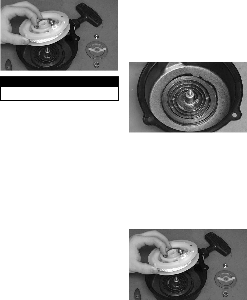
3-216
B605D
8. Remove the protective cover from the starter
handle and pull the rope out of the handle; then
untie the knot in the rope and remove the han-
dle.
NOTE: Do not remove the spiral spring unless
replacement is necessary. It should be visually
inspected in place to save time. If replacement is
necessary, follow steps 9-10.
9. Remove the spiral spring from the case by lift-
ing the spring end up and out. Hold the remain-
der of the spring with thumbs and alternately
release each thumb to allow the spring to gradu-
ally release from the case.
10. Unwind the rope from the reel and remove the
rope.
Cleaning and Inspecting
NOTE: Whenever a part is worn excessively,
cracked, or damaged in any way, replacement is
necessary.
1. Clean all components.
2. Inspect the springs and ratchet for wear or dam-
age.
3. Inspect the reel and case for cracks or damage.
4. Inspect the shaft for wear, cracks, or damage.
5. Inspect the rope for breaks or fraying.
6. Inspect the spiral spring for cracks, crystalliza-
tion, or abnormal bends.
7. Inspect the handle for damage, cracks, or deteri-
oration.
Assembling/Installing
1. If removed, insert the spiral spring into the case
with the outer end of the spring around the
mounting lug in the case; then wind it in a coun-
terclockwise direction until the complete spring
is installed.
NOTE: The spiral spring must seat evenly in the
recoil case.
B606D
2. Insert the rope through the hole in the reel and
tie a knot in the end; then wrap the rope counter-
clockwise around the reel leaving approximately
50 cm (20 in.) of rope free of the reel.
3. Apply low-temperature grease to the spring and
hub.
4. Thread the end of the rope through the guide
hole of the case; then thread the rope through the
handle and secure it with a double knot. Install
the protective cover into the handle.
5. Align the inner hook of the spiral spring with the
notch in the reel.
B605D
6. Install the ratchet onto its spring making sure the
end is properly installed on the reel.
! WARNING
Care must be taken when lifting the recoil free of the
case. Wear safety glasses to avoid injury.
FOR ARCTIC CAT ATV DISCOUNT PARTS CALL 606-678-9623 OR 606-561-4983
www.mymowerparts.com
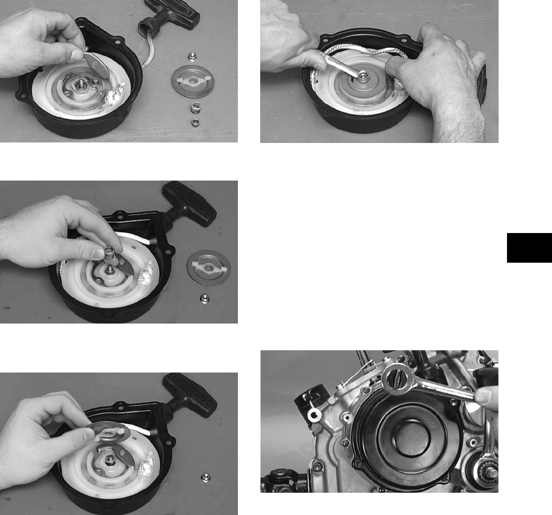
3-217
3
B604D
7. Install the shaft, spring, and the spring cover.
B603D
8. Install the friction plate with the ratchet guide
fitting into the ratchet.
B602D
9. While pushing down on the reel, install the nut.
Tighten securely.
B601D
10. With the 50 cm (20 in.) of rope exposed, hook
the rope in the notch of the reel.
11. Rotate the reel four turns counterclockwise; then
release the rope from the notch and allow the
rope to retract.
12. Pull the rope out two or three times to check for
correct tension.
NOTE: Increasing the rotations in step 11 will
increase spring tension.
13. Place the recoil starter assembly into position on
the left-side cover; then tighten the cap screws
to specifications.
CC039D
MEASURING SHIFT FORK
(Thickness)
NOTE: Whenever a shift fork is out of tolerance,
replacement is necessary.
1. Using a calipers, in turn measure the thickness
of the machined tip of each shift fork.
FOR ARCTIC CAT ATV DISCOUNT PARTS CALL 606-678-9623 OR 606-561-4983
www.mymowerparts.com
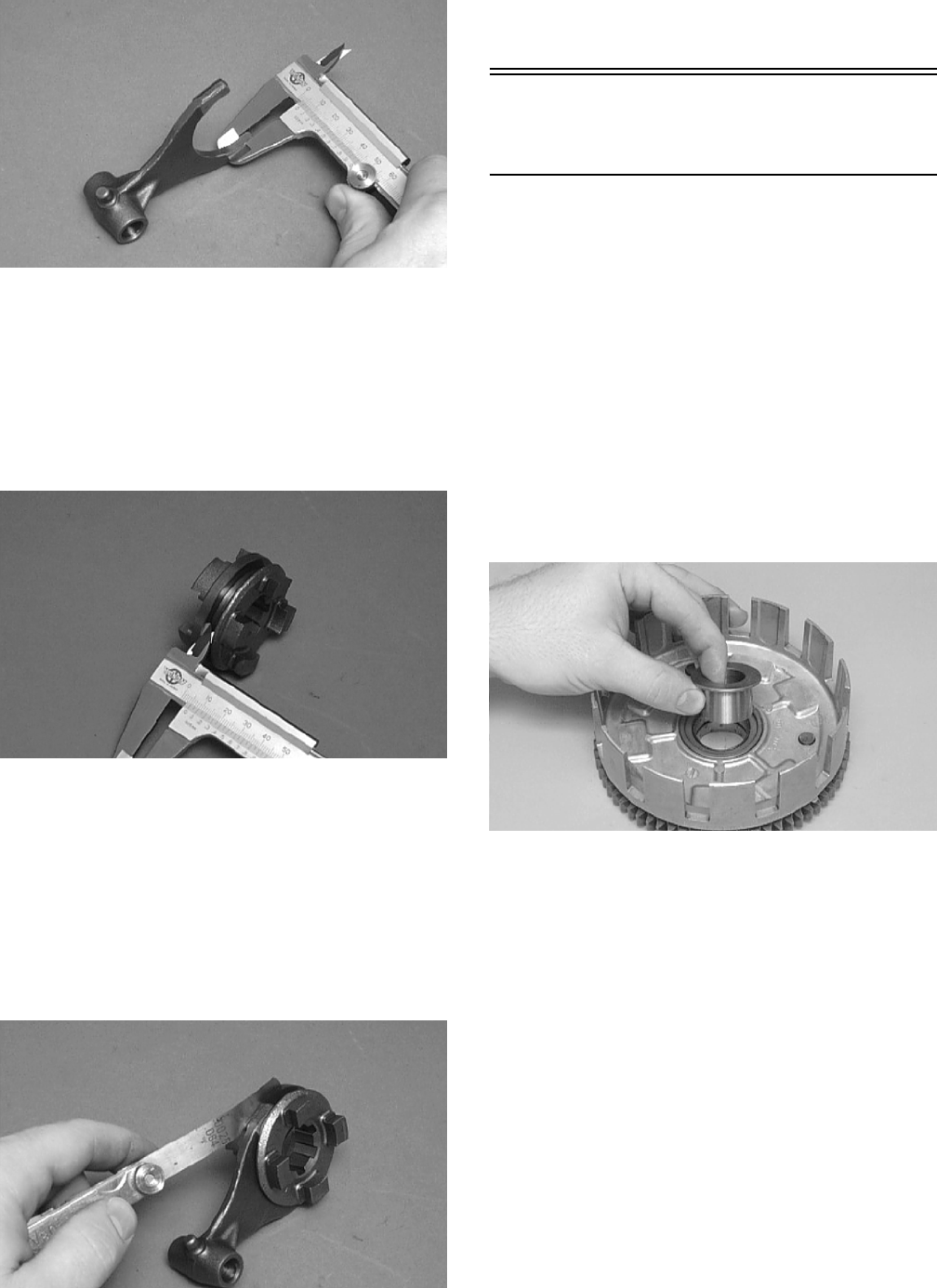
3-218
CC296D
2. Shift fork thickness must be within specifica-
tions.
MEASURING SHIFT FORK GROOVE
(Width)
1. Using a calipers, in turn measure the width of
each shift fork groove.
CC288D
2. Shift fork groove width must be within specifi-
cations.
MEASURING SHIFT FORK TO
GROOVE (Side Clearance)
1. In turn, insert each shift fork into its groove.
2. Using a feeler gauge, measure the clearance
between the shift fork and the groove.
CC292D
3. Shift fork to groove side clearance must be
within specifications.
Servicing Right-Side
Components
NOTE: Whenever a part is worn excessively,
cracked, damaged in any way, or out of tolerance,
replacement is necessary.
PRIMARY CLUTCH ASSEMBLY
(Inspecting/Measuring/Assembling)
NOTE: Prior to inspecting and measuring com-
ponents, it is recommended that all components
be removed from the primary gear assembly and
be cleaned.
NOTE: When removing components from the pri-
mary gear assembly, account for the bushing that
fits into the primary gear.
CC239D
Inspecting/Measuring Clutch
Driven Plate Warpage
1. Inspect each driven plate for warpage and burn
marks.
2. In turn place each driven plate on the surface
plate; then using a feeler gauge, measure
warpage in several locations.
FOR ARCTIC CAT ATV DISCOUNT PARTS CALL 606-678-9623 OR 606-561-4983
www.mymowerparts.com
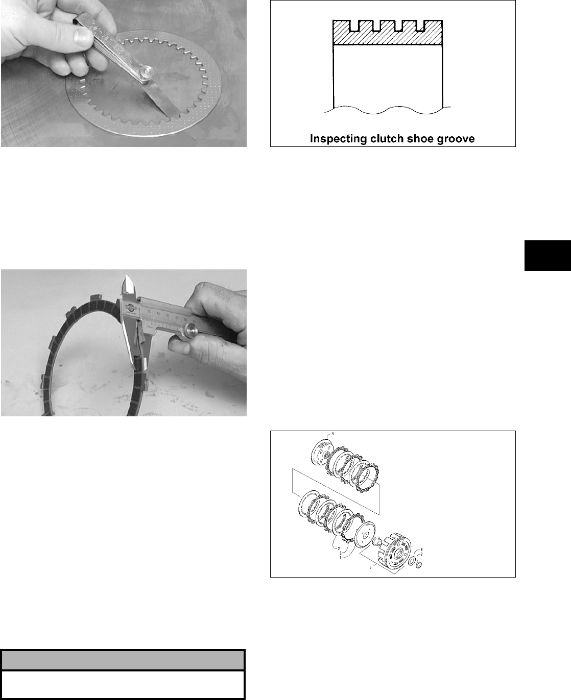
3-219
3
CC245D
3. Maximum driven plate warpage must not
exceed specifications.
Measuring Clutch Drive Plate
(Fiber) Thickness
1. Using a calipers, in turn measure the thickness
of each drive plate in several locations.
CC243D
2. Drive plate thickness must be within minimum
specifications.
3. If the fiber plate tabs are damaged, the plate
must be replaced.
4. Inspect the clutch sleeve hub for grooves or
notches. If grooves or notches are present,
replace the hub.
Inspecting Centrifugal Clutch Shoe
1. Inspect the clutch shoe for uneven wear, chips,
cracks, or discoloration.
2. Inspect the depth of the grooves in the clutch
shoes. If any shoe is worn to the bottom of the
groove, replace the complete set.
ATV1014
Inspecting Centrifugal Clutch
Housing
1. Inspect the clutch housing for burns, marks,
scuffs, cracks, scratches, or uneven wear.
2. If the housing is damaged in any way, the hous-
ing must be replaced.
Inspecting Primary One-Way Drive
1. Insert the drive into the centrifugal clutch hous-
ing.
2. Rotate the inner race by hand and verify the
inner race rotates only one direction.
3. If the inner race is locked in place or rotates both
directions, the drive assembly must be replaced.
Assembling Primary Clutch
737-731A
1. Place the clutch hub upside down into the pri-
mary gear assembly.
! CAUTION
Always replace clutch shoes as a complete set or
severe imbalance could occur.
KEY
1. Pressure Disc
2. Driven Plate
3. Drive Plate
4. Sleeve Hub
5. Primary Gear Assy
6. Washer
7. Washer
FOR ARCTIC CAT ATV DISCOUNT PARTS CALL 606-678-9623 OR 606-561-4983
www.mymowerparts.com
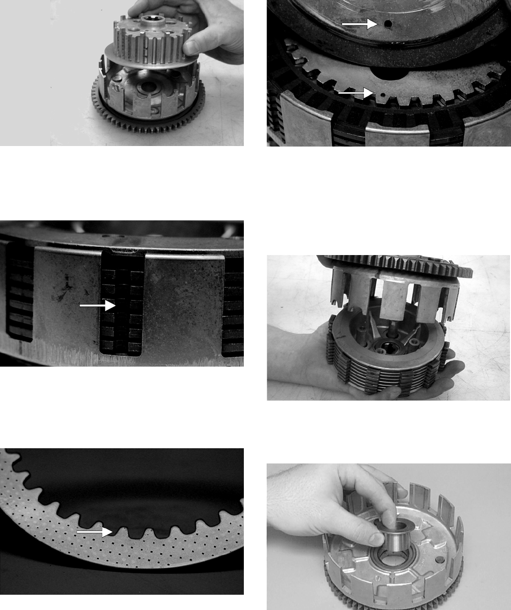
3-220
CC920
2. Alternately install the drive plates and driven
plates onto the hub (starting with and ending
with a drive plate) making sure the tabs with the
notches are all in line with each other.
CF044A
NOTE: When installing the driven plates for ease
of installation, make sure they are placed onto the
hub with the rounded side of the plates directed
down.
CF045A
3. Install the pressure plate onto the hub making
sure the alignment dots are correctly positioned.
CF047A
4. Place the primary gear assembly w/clutch hub
assembly in one hand, place the other hand on
top of the clutch hub assembly, and flip the
assembly over; then lift the primary gear assem-
bly off the clutch hub assembly being careful
not to disturb the drive plate notched tab orienta-
tion.
CC924
5. Place the primary gear assembly on a clean, flat
surface; then install the primary washer into the
assembly.
CC239D
6. Place the clutch hub assembly into the primary
gear assembly.
FOR ARCTIC CAT ATV DISCOUNT PARTS CALL 606-678-9623 OR 606-561-4983
www.mymowerparts.com

3-221
3
CC926
NOTE: The primary clutch assembly is now com-
pletely assembled for installation.
INSPECTING OIL PUMP
1. Inspect the pump for damage.
2. It is inadvisable to remove the screw securing
the pump halves. If the oil pump is damaged, it
must be replaced.
CD989A
Servicing Center
Crankcase Components
NOTE: Whenever a part is worn excessively,
cracked, damaged in any way, or out of tolerance,
replacement is necessary.
SECONDARY GEARS
NOTE: When checking and correcting secondary
gear backlash and tooth contact, the universal
joint must be secured to the front shaft or false
measurements will occur.
Checking Backlash
NOTE: The rear shaft and bevel gear must be
removed for this procedure. Also, always start with
the original shims on the rear shaft.
1. Place the left-side crankcase cover onto the
left-side crankcase half to prevent runout of the
secondary transmission output shaft.
2. Install the secondary driven output shaft assem-
bly onto the crankcase.
3. Mount the indicator tip of the dial indicator on
the secondary driven bevel gear.
4. While rocking the driven bevel gear back and
forth, note the maximum backlash reading on
the gauge.
5. Acceptable backlash range is 0.05-0.33 mm
(0.002-0.013 in.).
Correcting Backlash
NOTE: If backlash measurement is within the
acceptable range, no correction is necessary.
1. If backlash measurement is less than specified,
remove an existing shim, measure it, and install
a new thinner shim.
2. If backlash measurement is more than specified,
remove an existing shim, measure it, and install
a thicker shim.
NOTE: Continue to remove, measure, and install
until backlash measurement is within tolerance.
Note the following chart.
! CAUTION
The clutch hub and the pressure plate must be
seated in the proper position. If any of the incorrect
positions are used, the hub and plate will have clear-
ance between them and they will not operate prop-
erly.
FOR ARCTIC CAT ATV DISCOUNT PARTS CALL 606-678-9623 OR 606-561-4983
www.mymowerparts.com
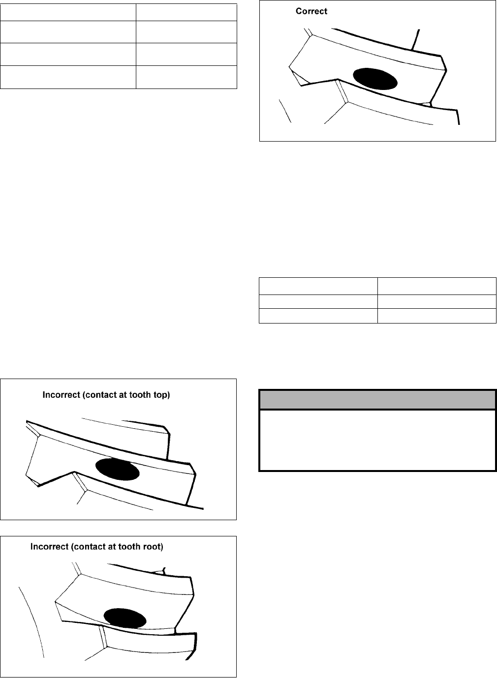
3-222
Checking Tooth Contact
NOTE: After correcting backlash of the second-
ary driven bevel gear, it is necessary to check
tooth contact.
1. Remove the secondary driven output shaft
assembly from the left-side crankcase half.
2. Clean the secondary driven bevel gear teeth of
old oil and grease residue.
3. Apply a thin, even coat of a machinist-layout
dye to several teeth of the gear.
4. Install the secondary driven output shaft assem-
bly.
5. Rotate the secondary driven bevel gear several
revolutions in both directions.
6. Examine the tooth contact pattern in the dye and
compare the pattern to the illustrations.
ATV-0103
ATV-0105
ATV-0104
Correcting Tooth Contact
NOTE: If tooth contact pattern is comparable to
the correct pattern illustration, no correction is
necessary.
If tooth contact pattern is comparable to an incorrect
pattern, correct tooth contact according to the fol-
lowing chart.
NOTE: To correct tooth contact, steps 1 and 2
(with NOTE) of “Correcting Backlash” must be fol-
lowed and the above “Tooth Contact/Shim Correc-
tion” chart must be consulted.
CRANKSHAFT ASSEMBLY
Measuring Connecting Rod
(Small End Inside Diameter)
1. Insert a snap gauge into the upper connecting
rod small end bore; then remove the gauge and
measure it with micrometer.
Backlash Measurement Shim Correction
Under 0.05 mm (0.002 in.) Decrease Shim
Thickness
At 0.05-0.33 mm
(0.002-0.013 in.)
No Correction Required
Over 0.33 mm (0.013 in.) Increase Shim
Thickness
Tooth Contact Shim Correction
Contacts at Top Decrease Shim Thickness
Contacts at Root Increase Shim Thickness
! CAUTION
After correcting tooth contact, backlash must again
be checked and corrected (if necessary). Continue
the correcting backlash/correcting tooth contact
procedures until they are both within tolerance val-
ues.
FOR ARCTIC CAT ATV DISCOUNT PARTS CALL 606-678-9623 OR 606-561-4983
www.mymowerparts.com
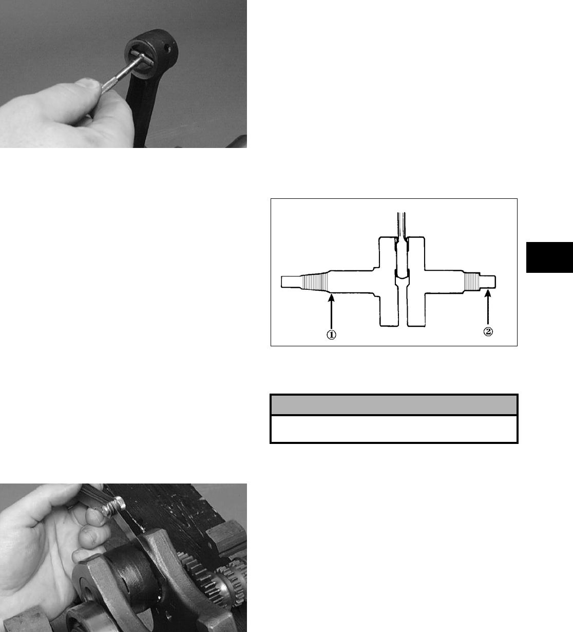
3-223
3
CC290D
2. Maximum diameter must not exceed specifica-
tions.
Measuring Connecting Rod
(Small End Deflection)
1. Place the crankshaft on a set of V blocks and
mount a dial indicator and base on the surface
plate. Position the indicator contact point against
the center of the connecting rod small end jour-
nal.
2. Zero the indicator and push the small end of the
connecting rod away from the dial indicator.
3. Maximum deflection must not exceed specifica-
tions.
Measuring Connecting Rod
(Big End Side-to-Side)
1. Push the lower end of the connecting rod to one
side of the crankshaft journal.
2. Using a feeler gauge, measure the gap between
the connecting rod and crankshaft journal.
CC289D
3. Acceptable gap range must be within specifica-
tions.
Measuring Connecting Rod
(Big End Width)
1. Using a calipers, measure the width of the
connecting rod at the big-end bearing.
2. Acceptable width range must be within specifi-
cations.
Measuring Crankshaft (Runout)
1. Place the crankshaft on a set of V blocks.
2. Mount a dial indicator and base on the surface
plate. Position the indicator contact at point 1 of
the crankshaft.
ATV-1074
3. Zero the indicator and rotate the crankshaft
slowly.
4. Maximum runout must not exceed specifica-
tions.
NOTE: Proceed to check runout on the other end
of the crankshaft by positioning the indicator con-
tact at point 2 and following steps 2-4.
Measuring Crankshaft
(Web-to-Web)
1. Using a calipers, measure the distance from the
outside edge of one web to the outside edge of
the other web.
! CAUTION
Care should be taken to support the connecting
rod when rotating the crankshaft.
FOR ARCTIC CAT ATV DISCOUNT PARTS CALL 606-678-9623 OR 606-561-4983
www.mymowerparts.com
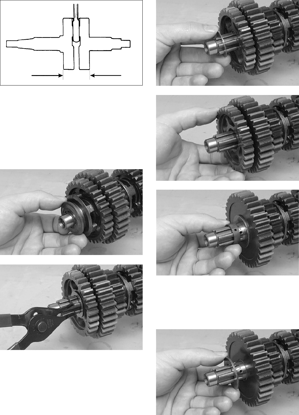
3-224
ATV-1017
2. Acceptable width range must be within specifi-
cations.
DRIVESHAFT
Disassembling
1. In order, remove the reverse dog, circlip,
washer, reverse driven gear, and bushing from
the driveshaft.
CC228D
CC227D
CC226D
CC225D
CC224D
NOTE: The teeth on the bushing must face the
1st driven gear.
2. Remove the 1st driven washer (right side); then
remove the 1st driven gear from the driveshaft.
CC223D
FOR ARCTIC CAT ATV DISCOUNT PARTS CALL 606-678-9623 OR 606-561-4983
www.mymowerparts.com
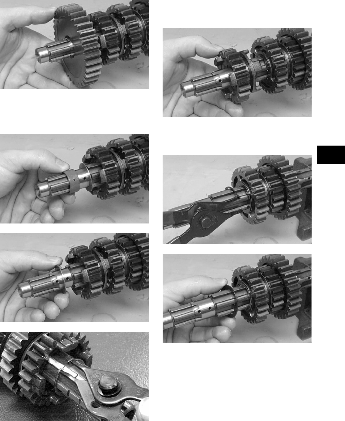
3-225
3
CC222D
3. Remove the 1st driven bushing; then remove the
1st driven washer (left side) from the shoulder
of the splined shaft. Remove the 4th driven cir-
clip.
CC221D
CC220D
CC508D
4. Remove the 4th driven gear from the driveshaft.
Note the four small dogs facing toward the 3rd
driven gear for assembling purposes.
CC219D
5. Remove the 3rd driven circlip; then remove the
3rd driven lock washer (right side) from the
driveshaft.
CC216D
CC215D
6. Remove the 3rd driven gear from the driveshaft.
FOR ARCTIC CAT ATV DISCOUNT PARTS CALL 606-678-9623 OR 606-561-4983
www.mymowerparts.com
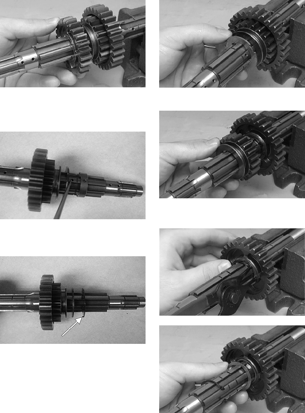
3-226
CC214D
7. Remove the 3rd driven bushing from the drive-
shaft. Note the location of the oil feed hole in
the bushing and the matching oil supply hole in
the driveshaft for assembling purposes.
CD248
8. Remove the 3rd driven lock washer (left side)
from the driveshaft. Note the tabs facing toward
the 5th driven gear for assembling purposes.
CD247A
9. Remove the next 3rd driven lock washer (left
side) by rotating it out of the groove. Note the
groove closest to the 5th driven gear for assem-
bling purposes.
CC211D
10. Remove the 5th driven gear from the driveshaft.
CC210D
11. In order, remove the 2nd driven circlip, washer,
gear, and bushing from the driveshaft.
CC209D
CC208D
FOR ARCTIC CAT ATV DISCOUNT PARTS CALL 606-678-9623 OR 606-561-4983
www.mymowerparts.com
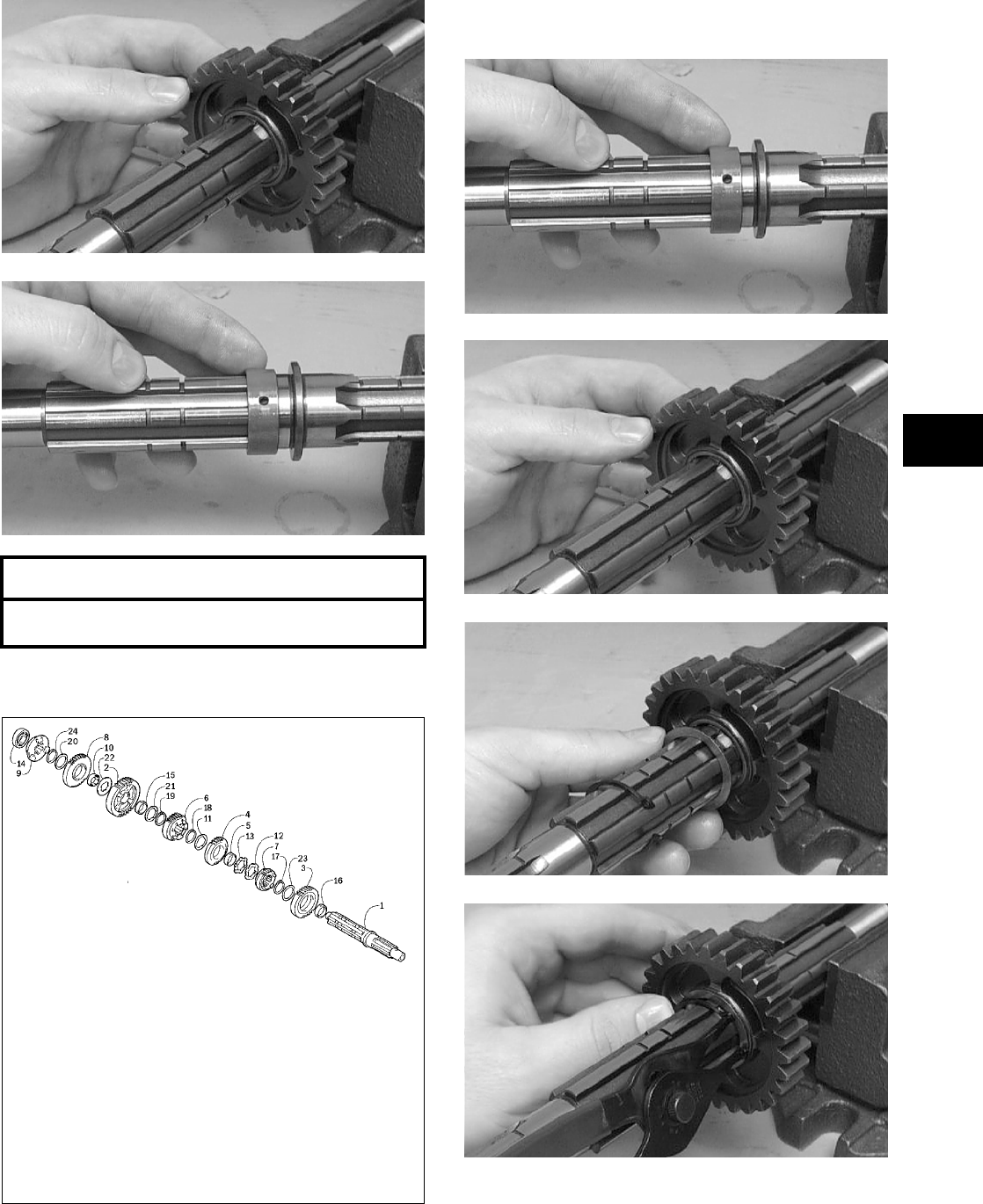
3-227
3
CC207D
CC206D
Assembling
737-733A
1. In order, install the 2nd driven bushing, gear,
washer, and circlip onto the driveshaft.
CC206D
CC207D
CC208D
CC209D
2. Install the 5th driven gear onto the driveshaft.
AT THIS POINT
To service secondary gears, see Servicing Center
Crankcase Components in this sub-section.
KEY
1. Driveshaft
2. 1st Driven Gear
3. 2nd Driven Gear
4. 3rd Driven Gear
5. 3rd Driven Bushing
6. 4th Driven Gear
7. 5th Driven Gear
8. Reverse Driven Gear
9. Reverse Dog
10. Reverse Driven Bushing
11. 3rd Driven Lock Washer —
Right
12. 3rd Driven Lock Washer —
Left
13. 3rd Driven Lock Washer —
Left
14. Driveshaft Bearing
15. 1st Driven Bushing
16. 2nd Driven Bushing
17. 2nd Driven Circlip
18. 3rd Driven Circlip
19. 4th Driven Circlip
20. Reverse Driven Washer
21. 1st Driven Washer — Left
22. 1st Driven Washer — Right
23. 2nd Driven Washer
24. Reverse Driven Circlip
FOR ARCTIC CAT ATV DISCOUNT PARTS CALL 606-678-9623 OR 606-561-4983
www.mymowerparts.com
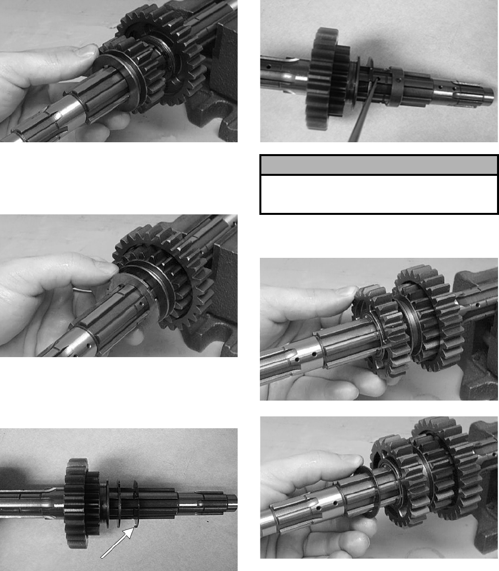
3-228
CC210D
3. Install the 3rd driven lock washer (left side).
Lock it into the groove closest to the 5th driven
gear (as noted in disassembling) by rotating it
when it is in the groove.
CC211D
4. Install the next 3rd driven lock washer (left side)
onto the driveshaft making sure the tabs are fac-
ing toward the 5th driven gear. Make sure the
tabs intertwine with the 3rd driven lock washer.
CD247A
5. Install the 3rd driven bushing onto the driveshaft
making sure the oil feed hole in the bushing
aligns with the appropriate oil supply hole in the
driveshaft (as noted in disassembling).
CD248
6. In order, install the 3rd driven gear, lock washer
(right side), and circlip onto the driveshaft.
CC214D
CC215D
! CAUTION
It is very important to assure the oil feed hole in the
bushing and oil supply hole in the driveshaft align. If
not aligned, engine damage will result.
FOR ARCTIC CAT ATV DISCOUNT PARTS CALL 606-678-9623 OR 606-561-4983
www.mymowerparts.com
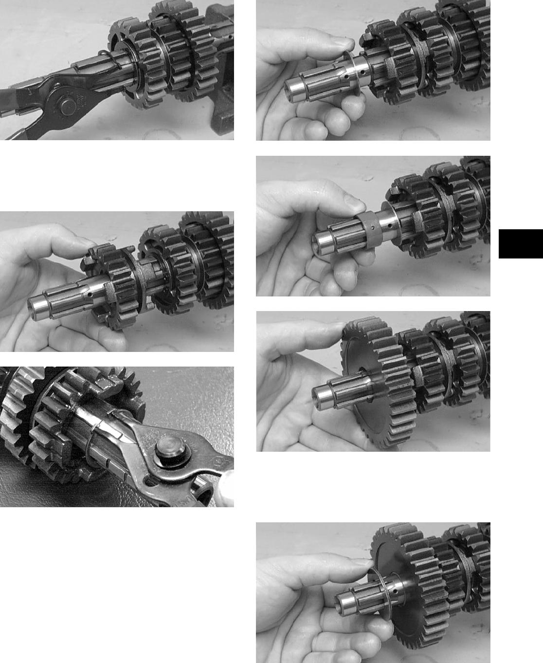
3-229
3
CC216D
7. Install the 4th driven gear onto the driveshaft
making sure the four small dogs are facing
toward the 3rd driven gear as noted in disassem-
bling; then secure with the circlip.
CC219D
CC508D
8. Install the 1st driven washer (left side) onto the
shoulder of the splined shaft; then install the 1st
driven bushing and gear.
CC220D
CC221D
CC222D
9. Install the 1st driven washer (right side) on the
shaft making sure it lines up with the groove in
the shaft; then turn the washer locking it on the
shaft.
CC223D
FOR ARCTIC CAT ATV DISCOUNT PARTS CALL 606-678-9623 OR 606-561-4983
www.mymowerparts.com
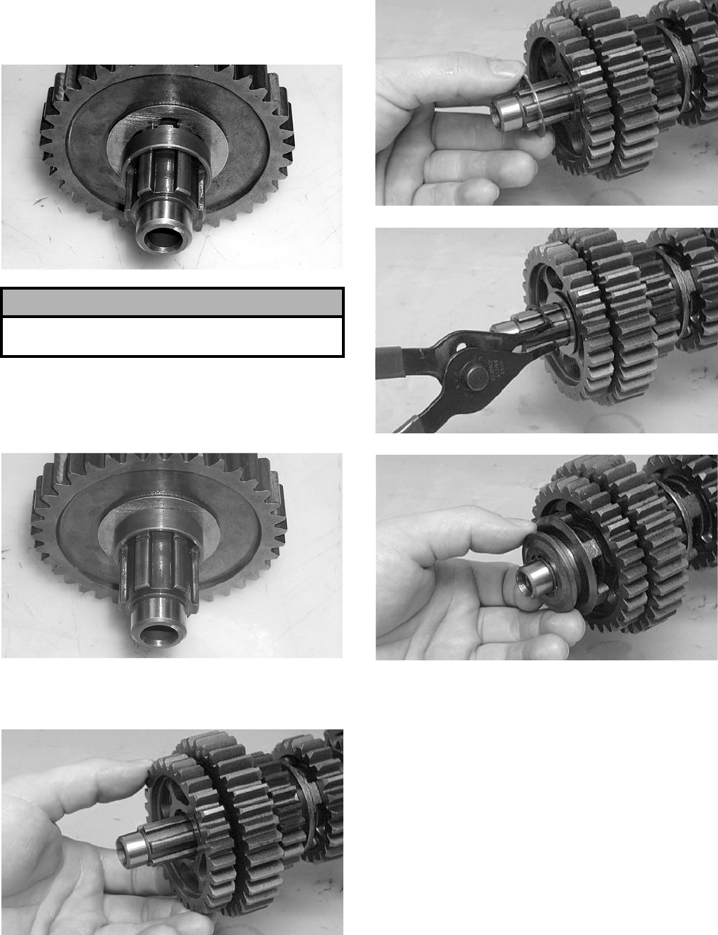
3-230
10. Slide the reverse driven gear bushing onto the
shaft making sure the oil port in the bushing
aligns with the oil port on the shaft.
CC842
11. Move the washer in the shaft groove until the
notches in the washer align with the tabs on the
bushing; then slide the bushing up tight against
the washer.
CC843
12. In order, install the reverse driven gear, washer,
circlip, and reverse dog onto the driveshaft.
CC225D
CC226D
CC227D
CC228D
NOTE: The driveshaft is now completely assem-
bled for installation.
COUNTERSHAFT
Disassembling
1. Remove the 2nd drive gear and washer from the
countershaft.
! CAUTION
Failure to align the oil ports will result in serious
engine damage.
FOR ARCTIC CAT ATV DISCOUNT PARTS CALL 606-678-9623 OR 606-561-4983
www.mymowerparts.com
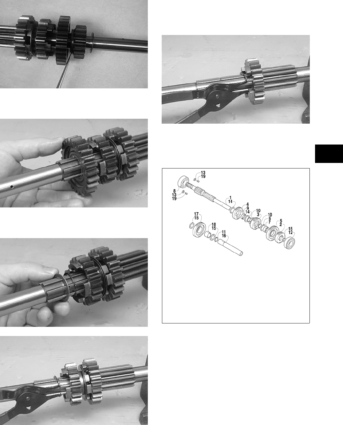
3-231
3
CD242
2. Remove the 5th drive gear from the counter-
shaft.
CC203D
3. Remove the 5th drive washer and 5th drive cir-
clip from the countershaft.
CC201D
CC200D
4. Remove the 3rd drive gear from the countershaft.
5. Remove the 4th drive circlip securing the 4th
drive gear on the countershaft; then remove the
first 4th drive washer and 4th drive gear.
Account for the bushing.
CC199D
6. Remove the other 4th drive washer from the
countershaft.
Assembling
738-294A
1. Install the 4th drive washer onto the counter-
shaft.
2. Install the 4th drive gear making sure the bush-
ing is in position; then install the other 4th drive
washer onto the countershaft. Secure with the
circlip.
KEY
1. Countershaft
2. 2nd Drive Gear
3. 3rd Drive Gear
4. 4th Drive Gear
5. 5th Drive Gear
6. 5th Drive Washer
7. 5th Drive Bushing
8. Shaft Bearing
9. 4th Drive Bushing
10. 4th Drive Circlip
11. 5th Drive Circlip
12. Shaft Bearing
13. Retainer
14. 4th Drive Washer
15. Washer
16. Reverse Idle Shaft
17. Reverse Idle Gear
18. Reverse Idle Bushing
19. Screw
FOR ARCTIC CAT ATV DISCOUNT PARTS CALL 606-678-9623 OR 606-561-4983
www.mymowerparts.com
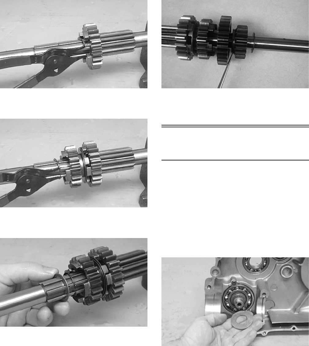
3-232
CC199D
3. Install the 3rd drive gear; then install the 5th
drive circlip onto the countershaft.
CC200D
4. Install the 5th drive washer and 5th drive gear
onto the countershaft.
CC201D
5. Install the 2nd drive gear and washer onto the
countershaft.
CD242
NOTE: The countershaft is now completely
assembled for installation.
Assembling Crankcase
Half
NOTE: For ease of assembly, install components
on the left-side crankcase half.
NOTE: If the output shaft and gear were
removed, make sure that the proper shim is
installed.
1. To install the output shaft and gear, place the
shaft into position with proper shims, slide the
gear onto the shaft, and secure with a new nut
tightened to specifications.
CC117D
FOR ARCTIC CAT ATV DISCOUNT PARTS CALL 606-678-9623 OR 606-561-4983
www.mymowerparts.com
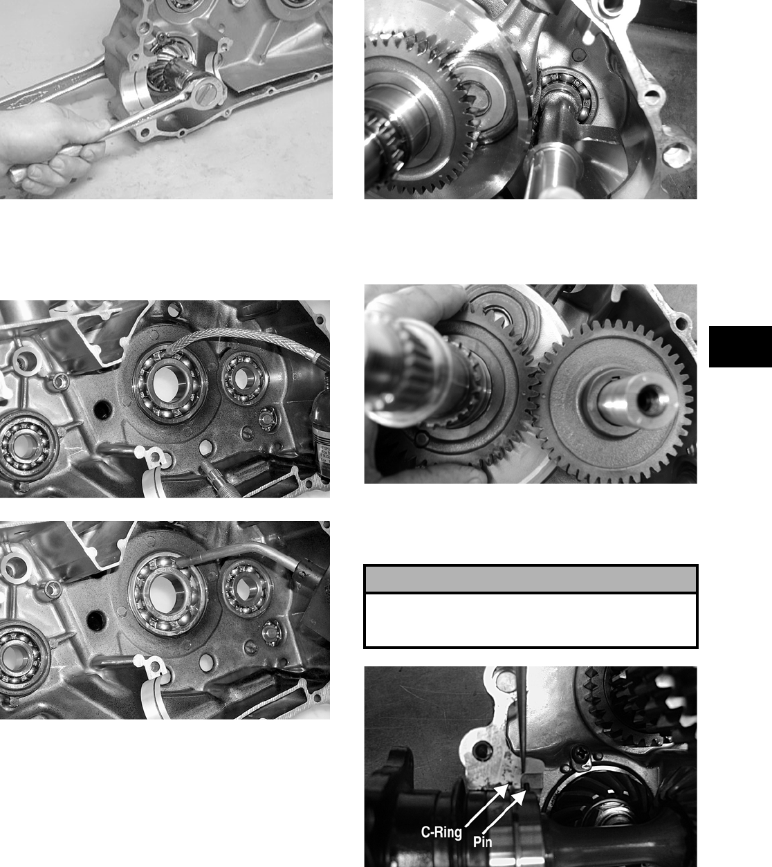
3-233
3
CC116D
2. Apply a liberal amount of engine oil to the
crankshaft bearing. Using a propane torch, heat
the bearing until the oil begins to smoke; then
slide the crankshaft assembly into place.
CC688
CC689
NOTE: If heating the bearing is not possible, the
crankshaft can be installed using a crankshaft
installing tool.
3. Install the crank balancer.
NOTE: It will be necessary to rotate the crank
balancer until the counterweight is directed away
from the crankshaft; then rotate the crankshaft
clockwise into the journal area to allow the bal-
ancer to be fully seated.
CD832A
4. With the key in position, slide the driven gear
onto the crank balancer making sure the timing
marks are aligned.
CD826
5. Place the bearing C-ring into position in the
crankcase; then install the front output shaft and
rear shaft assemblies.
CD268A
6. Simultaneously, install the driveshaft and coun-
tershaft assemblies making sure the washer is on
the countershaft.
! CAUTION
The bearing pins must be positioned into the crank-
case correctly or damage to the crankcase may
occur.
FOR ARCTIC CAT ATV DISCOUNT PARTS CALL 606-678-9623 OR 606-561-4983
www.mymowerparts.com
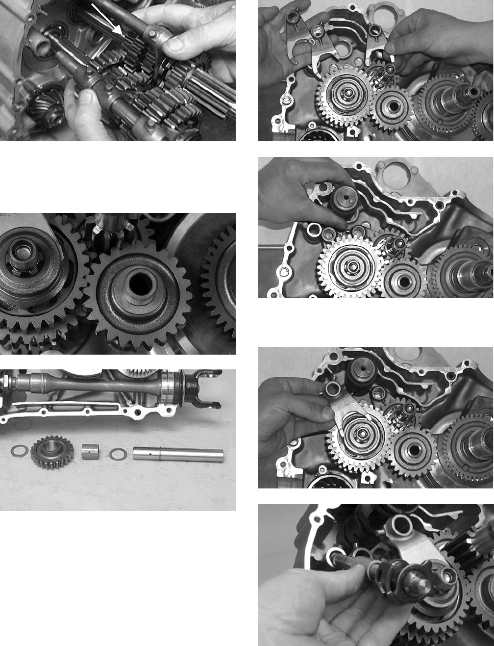
3-234
CD232A
7. Install the reverse idle shaft with circlip making
sure the oil hole in the shaft is facing downward;
then install a washer, bushing, reverse idle gear,
and a washer.
CF055
CC231D
8. Place each of the four shift forks into its respec-
tive gear or dog as noted during disassembling;
then install the gear shift cam.
CC107D
CC106D
9. Engage the four forks to the gear shift cam; then
install the reverse shift cam and spacer.
CC105D
CC103D
10. Install the two gear shift shafts; then verify that
the two crankcase half alignment pins are in
place.
FOR ARCTIC CAT ATV DISCOUNT PARTS CALL 606-678-9623 OR 606-561-4983
www.mymowerparts.com
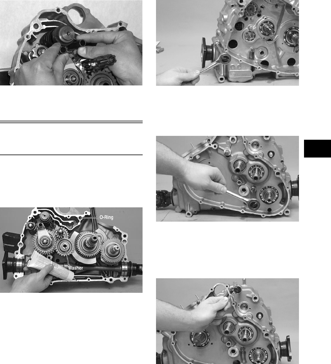
3-235
3
CC104D
NOTE: Prior to joining crankcase halves, turn the
shift cam to ensure all gears shift properly.
Joining Crankcase
Halves
1. Place the O-ring in the left-side crankcase half
and verify that the washer is on the idler shaft;
then apply Three Bond Sealant to the mating
surfaces. Place the right-side half onto the
left-side half.
CC234DA
2. Using a plastic mallet, lightly tap the case halves
together until cap screws can be installed.
3. From the left side, install the three case half 8
mm cap screws (two inside the case); then
tighten only until snug.
NOTE: Rotate the shafts back and forth to
ensure no binding or sticking occurs.
CC098D
4. From the right side, install the three case half 8
mm cap screws; then tighten only until snug.
NOTE: Rotate the shafts back and forth to
ensure no binding or sticking occurs.
CC097D
5. From the left side, install the seven case half 6
mm cap screws noting the location of the wiring
form; then tighten only until snug.
NOTE: Rotate the shafts back and forth to
ensure no binding or sticking occurs.
CC096D
6. From the right side, install the five case half 6
mm cap screws (one inside the case); then
tighten only until snug.
NOTE: Rotate the shafts back and forth to
ensure no binding or sticking occurs.
FOR ARCTIC CAT ATV DISCOUNT PARTS CALL 606-678-9623 OR 606-561-4983
www.mymowerparts.com
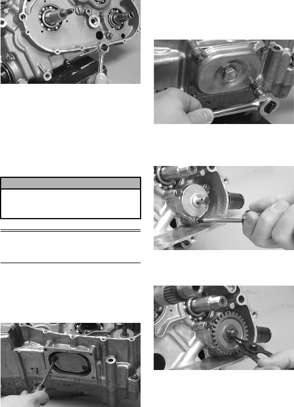
3-236
CC095D
7. In a crisscross/case-to-case pattern, tighten the 8
mm cap screws (from steps 3-4) until the halves
are correctly joined; then tighten to specifications.
NOTE: Rotate the shafts back and forth to
ensure no binding or sticking occurs.
8. In a crisscross/case-to-case pattern, tighten the 6
mm cap screws (from steps 5-6) to specifications.
NOTE: Rotate the shafts back and forth to
ensure no binding or sticking occurs.
Installing Right-Side
Components
A. Oil Strainer/Oil Pump
B. Gear Shift Shaft
1. Place the oil strainer into position beneath the
crankcase and tighten securely with the Phil-
lips-head cap screws.
CC163D
2. Place the strainer cap into position on the
strainer making sure a new O-ring is properly
installed and secure with the cap screws; then
install and tighten the oil drain plug to specifica-
tions.
CC091D
3. Place the oil pump into position in the crankcase
and secure with the three Phillips-head screws
coated with blue Loctite #243. Tighten to speci-
fications.
CC090D
4. Place the pin and washer into position on the oil
pump shaft, install the oil pump driven gear, and
secure with the circlip.
CC088D
5. Place the gear shift cam plate and guide onto the
gear shift cam making sure the alignment pin
was installed. Secure assembly with the cap
screw coated with blue Loctite #243. Tighten
securely.
! CAUTION
After completing center crankcase components,
proceed to Installing Right-Side Components, to
Installing Left-Side Components, and to In- stalling
Top-Side Components.
FOR ARCTIC CAT ATV DISCOUNT PARTS CALL 606-678-9623 OR 606-561-4983
www.mymowerparts.com
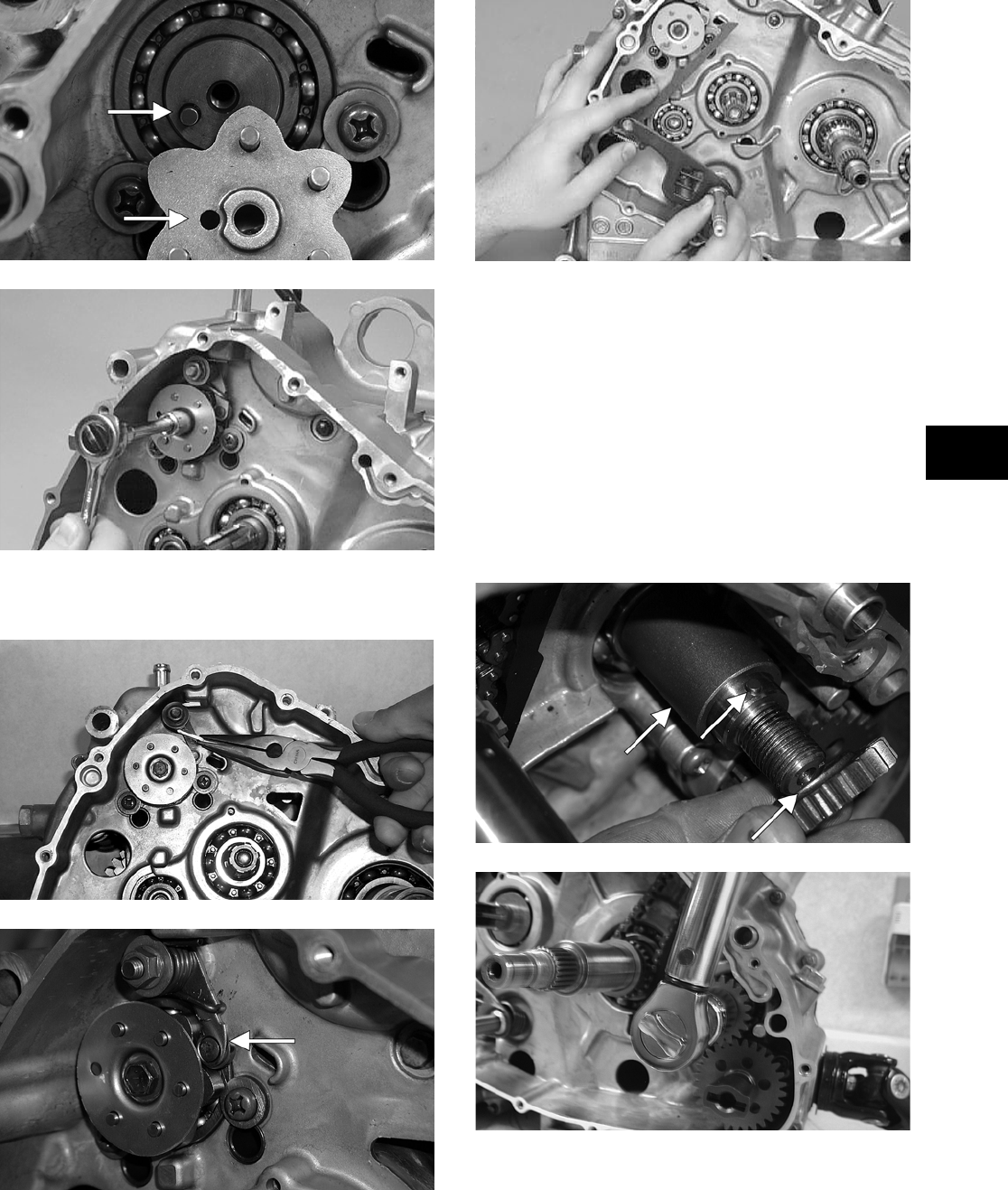
3-237
3
CF073A
CC164D
6. Attach the spring to the gear shift cam stopper
arm.
CC086D
CF072A
7. Install the gear shift shaft.
CC085D
C. Primary Driven Gear
D. Primary Driven Clutch
E. Primary Drive Clutch Shoe
NOTE: Steps 1-7 in the preceding sub-section
must precede this procedure.
8. Install the spacer, pin, and oil pump drive gear
onto the crank balancer shaft making sure the
shoulder of the drive gear is facing inward
toward the crankcase; then secure with the
washer and nut tightened to specifications.
CF070A
CD481
9. Place the chain into the crankcase; then secure it
from the top side with a wire for ease of assem-
bling.
FOR ARCTIC CAT ATV DISCOUNT PARTS CALL 606-678-9623 OR 606-561-4983
www.mymowerparts.com
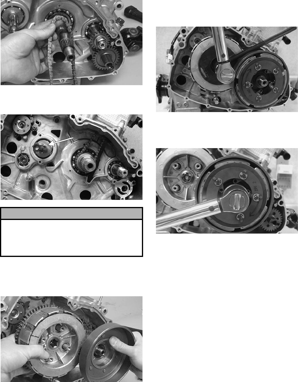
3-238
CC079D
10. Install the primary driven washers onto the
driveshaft and crankshaft.
CD198B
11. Simultaneously, place the primary clutch assem-
bly and the starter clutch housing on their
respective shafts making sure the sleeve is prop-
erly positioned in the primary assembly.
CC078D
NOTE: Note the alignment mark scribed on the
primary driven gear assembly during disassembly.
12. Using the Clutch Sleeve Hub Holder (p/n
0444-007), install the nut and washer. Tighten to
specifications.
CD479
13. Place the primary drive one-way clutch into the
starter clutch housing noting the word OUT-
SIDE for proper placement.
CD482
14. Install the clutch shoe and washer; then secure
with the starter clutch shoe nut (left-hand
threads). Tighten to specifications; then using a
center punch, stake the nut.
15. Install the release roller assembly making sure
the four springs are in position; then using a
crisscross pattern, tighten the four cap screws
securely.
NOTE: Tighten the four roller assembly cap
screws in a crisscross pattern making sure there
is no clearance between the clutch plates when
secured.
! CAUTION
The clutch sleeve hub and the pressure plate must
be seated in the proper position. If any of the incor-
rect positions are used, the hub and plate will have
clearance between them and they will not operate
properly.
FOR ARCTIC CAT ATV DISCOUNT PARTS CALL 606-678-9623 OR 606-561-4983
www.mymowerparts.com
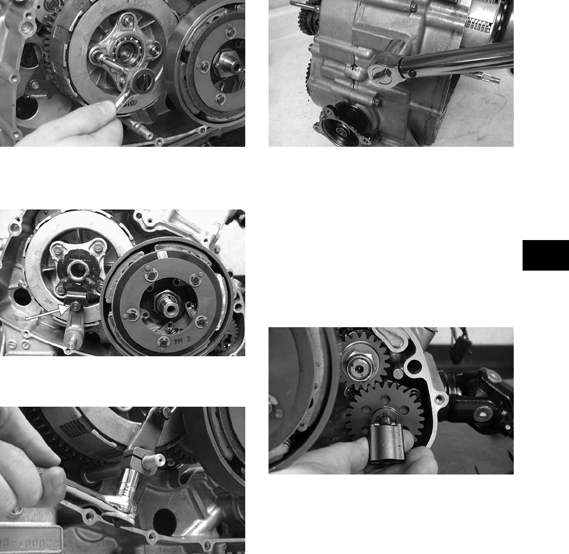
3-239
3
CC074D
16. Install the clutch release arm and release roller
guide making sure the release roller and guide
are aligned.
CD166A
17. Secure the clutch release arm with the cap screw
coated with blue Loctite #243. Tighten securely.
CC073D
18. Install the reverse cam stopper housing and gas-
ket making sure the stopper and spring are cor-
rectly positioned. Tighten to specifications.
CD494
F. Water Pump
G. Oil Filter
NOTE: Steps 1-18 of the preceding sub-sections
must precede this procedure.
NOTE: Lubricate all internal components with
5W-30 oil prior to installing the right-side cover.
19. Place the water pump drive joint into position on
the water pump shaft making sure the pin is
properly positioned.
CF067
NOTE: Care should be taken that the alignment
pins are installed in the right-side cover.
20. Place the gasket and right-side cover into posi-
tion making sure the release roller guide remains
correctly positioned and that the water pump
drive adapter aligns; then install the fifteen cap
screws. Note the proper location of the long cap
screw with rubber washer.
FOR ARCTIC CAT ATV DISCOUNT PARTS CALL 606-678-9623 OR 606-561-4983
www.mymowerparts.com
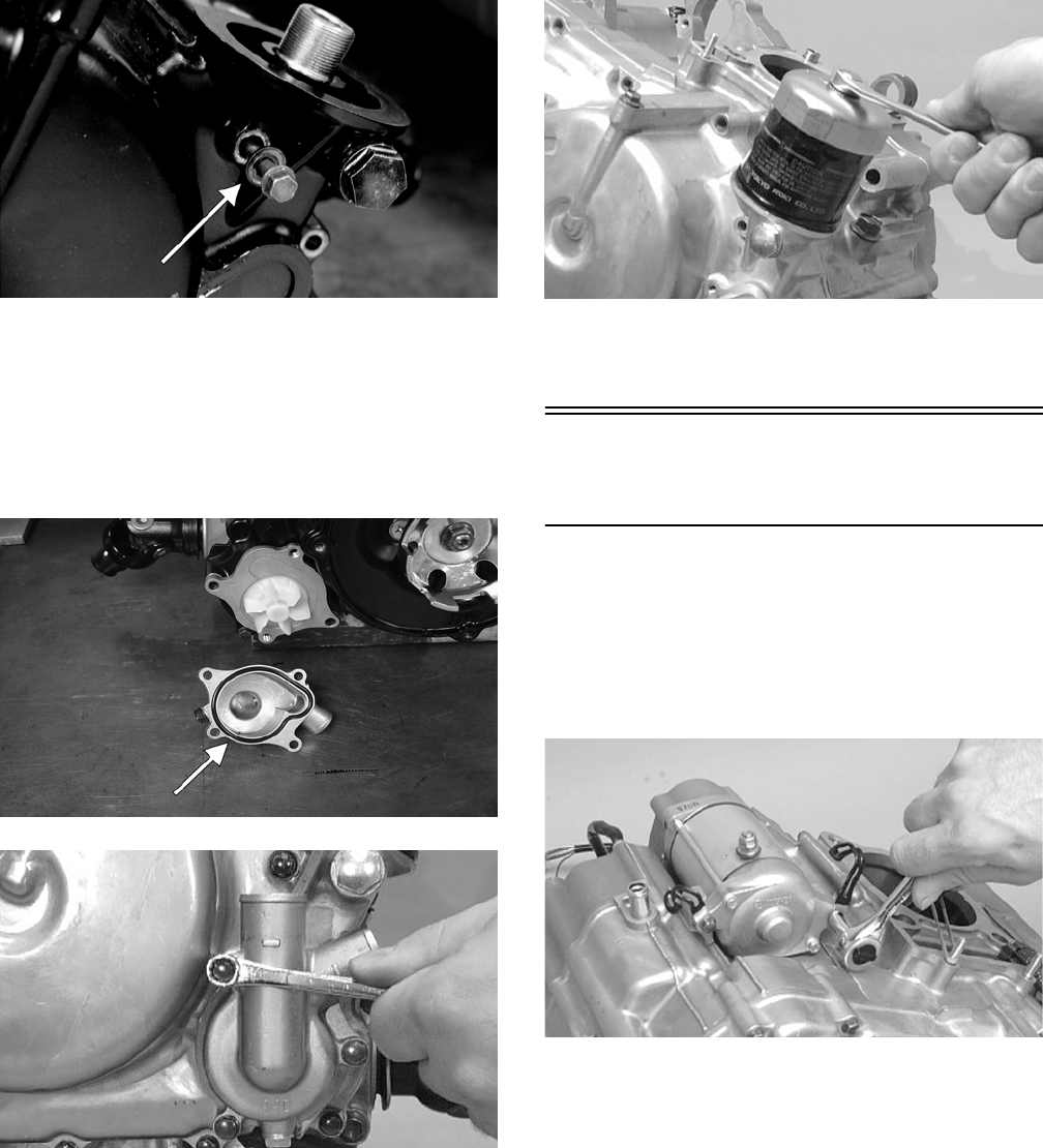
3-240
CF039A
21. Tighten the cap screws in a crisscross pattern to
specifications.
22. Place the water pump cover onto the right-side
cover making sure the new O-ring is properly
positioned. Tighten securely with the three cap
screws.
CD910A
CC027D
23. Using the oil filter wrench, install a new oil fil-
ter.
CC067D
24. Install the coolant hose on the water pump and
secure with the clamp.
Installing Left-Side
Components
A. Idle Gear Assembly
B. Magneto Rotor
1. Place the starter into position on the crankcase
and secure with the cap screws. Note the posi-
tion of the wiring form.
CC065D
2. Place the shift-indicator sending unit into posi-
tion making sure the contacts and springs are
inside the case and a well-oiled O-ring is properly
positioned. Secure with Phillips-head screws.
FOR ARCTIC CAT ATV DISCOUNT PARTS CALL 606-678-9623 OR 606-561-4983
www.mymowerparts.com
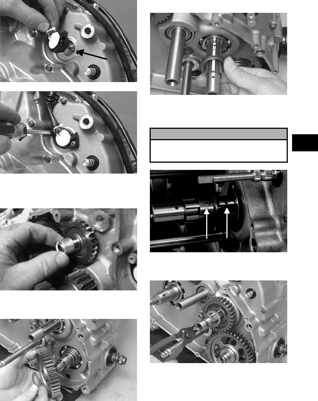
3-241
3
CC049D
CC048D
3. Install the starter idle gear pin into the crankcase;
then with the beveled side of the idle gear facing
the crankcase, install the idle gear and spacer.
CD138
4. Place the bushing onto the output shaft; then
install the driven gear and washer.
CC063D
5. Install the spacer onto the driveshaft.
CC258D
6. Place the splined bushing onto the driveshaft
making sure the oil hole of the splined bushing
aligns with the oil hole of the driveshaft.
CF038A
7. In turn on the driveshaft, install the #1 drive
gear and washer; then secure with the circlip.
CC059D
8. Place the select sliding dog gear and washer
onto the driveshaft; then place the #2 drive gear
onto the driveshaft making sure the bushing and
washer follow on the driveshaft.
! CAUTION
It is important that the oil holes in the splined bush-
ing and driveshaft align. If they are not aligned,
major damage will occur from lack of lubrication.
FOR ARCTIC CAT ATV DISCOUNT PARTS CALL 606-678-9623 OR 606-561-4983
www.mymowerparts.com
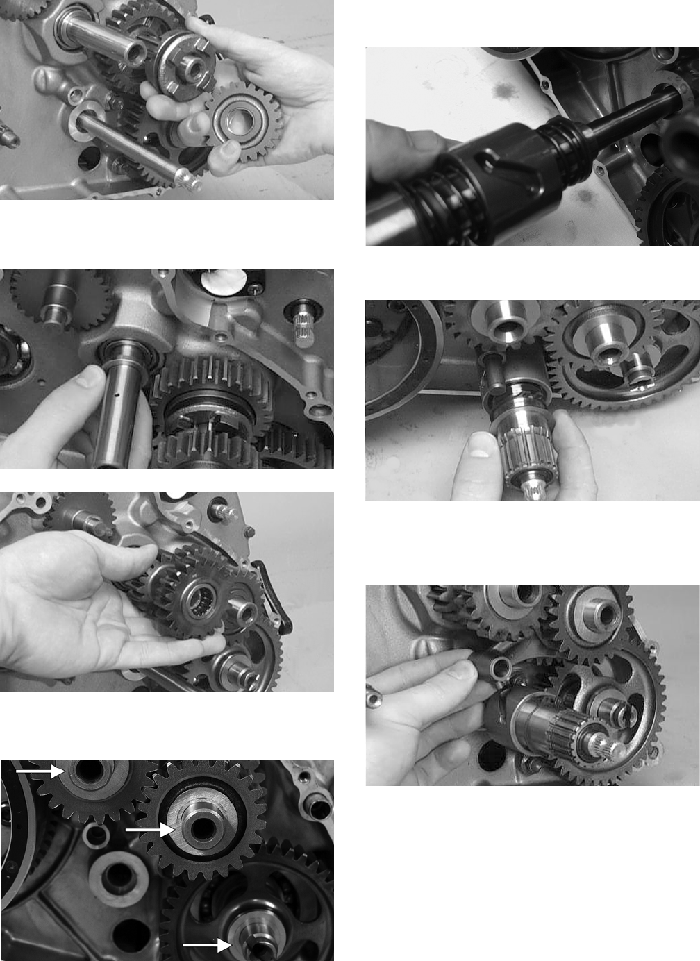
3-242
CC061D
9. Place the idle gear spacer and idle gear onto the
countershaft.
CC262D
CC060D
10. Place a washer on the driveshaft, the counter-
shaft, and the driven shaft.
CF075A
11. With the slot in the shift shaft assembly facing
upward, place the assembly on the fixed shaft.
CD147
12. Place the left shaft washer on the shift shaft.
CC333D
13. With the shift fork peg positioned in the shift
shaft assembly slot, install the shift fork in the
select sliding dog gear.
CC329D
14. Slide the shift fork shaft through the shift fork
and into the crankcase boss.
FOR ARCTIC CAT ATV DISCOUNT PARTS CALL 606-678-9623 OR 606-561-4983
www.mymowerparts.com
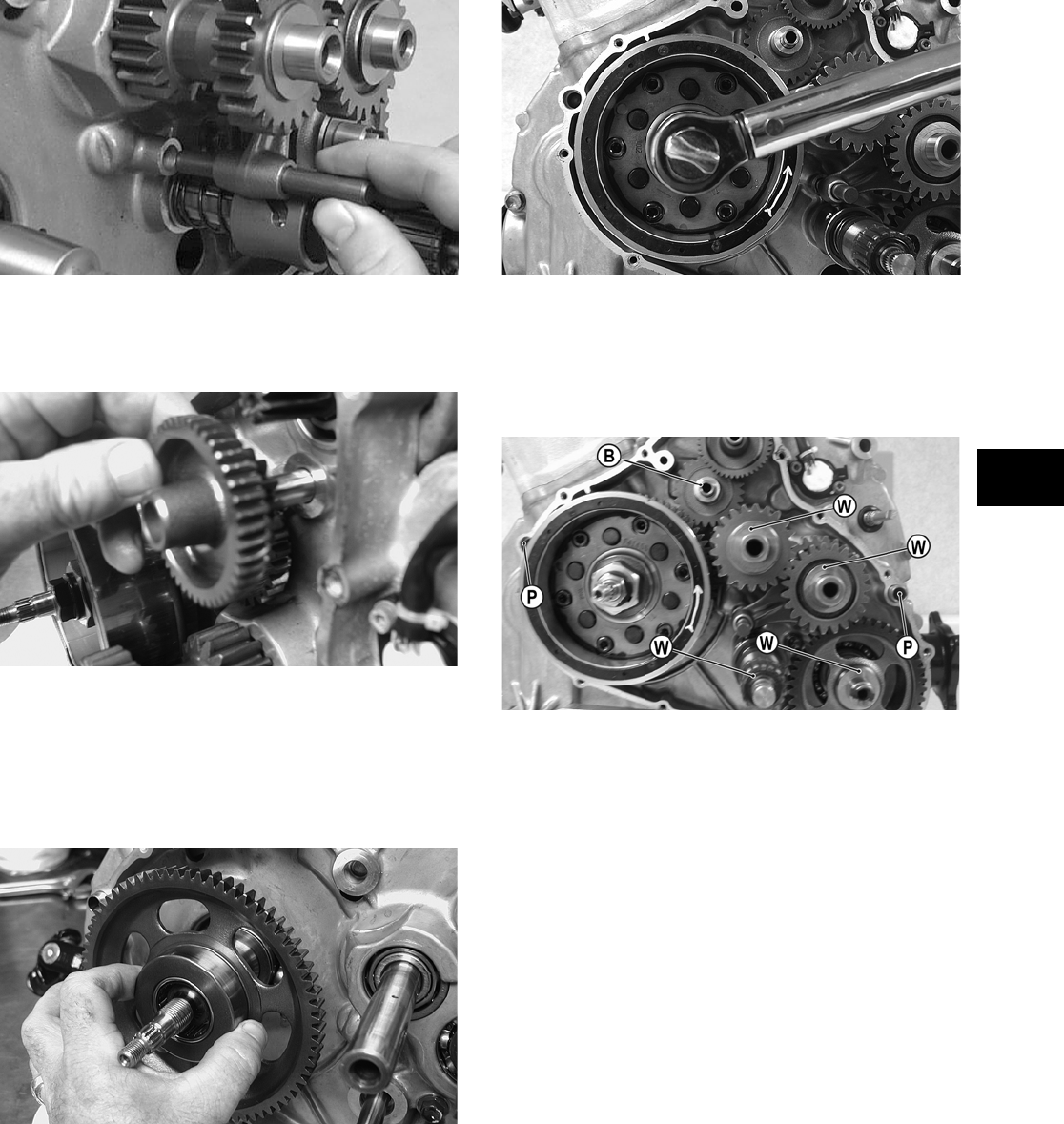
3-243
3
CC330D
15. Insert the pin into the starter gear assembly boss
in the crankcase; then install starter idler gear
#1.
CD136
16. Place a washer on each end of the starter gear
assembly and install in the crankcase.
17. Place a thrust washer onto the crankshaft; then
install the starter clutch gear assembly onto the
crankshaft. Place the key into its notch.
CD155
18. Place the rotor/flywheel into position on the
crankshaft; then install the nut on the crankshaft
and tighten until the rotor/flywheel is properly
seated. Tighten to specifications.
CD444
19. Install the two alignment pins into the left crank-
case half.
NOTE: Make sure that four washers, one bush-
ing, and two alignment pins are in place.
CD134A
C. Cover
D. Speed Sensor Housing
E. Hi/Low Shifter Assembly
F. Recoil Starter
NOTE: Steps 1-19 in the preceding sub-section
must precede this procedure.
20. Place the gasket and left-side cover into position
on the crankcase.
NOTE: It may be necessary to push or pull the
splined Hi/Low range shift shaft to establish
cover/crankcase mating.
21. Install the fourteen cap screws to secure the
left-side cover. Do not tighten at this time. Note
the location of the long cap screw with rubber
washer.
FOR ARCTIC CAT ATV DISCOUNT PARTS CALL 606-678-9623 OR 606-561-4983
www.mymowerparts.com
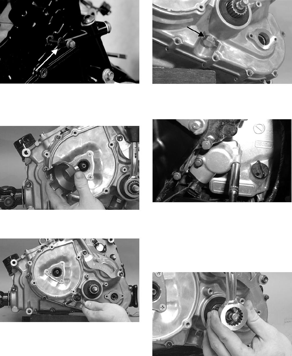
3-244
CF037A
22. Place the starter cup into position on the crank-
shaft making sure a new, lubricated O-ring is
inside the cup. Tighten the flange nut to specifi-
cations.
CC041D
23. In a crisscross pattern, tighten the cap screws
(from step 21) to specifications.
CC047D
24. Place the shift stop housing assembly into posi-
tion beneath the shift shaft housing making sure
the spring and stopper are correctly positioned.
Tighten to specifications.
CC054D
25. Place the speed sensor housing and gasket into
position and secure with the two cap screws.
Tighten securely.
CD069
26. Install the inside circlip onto the hi/low range
shift shaft with the sharp side of the circlip fac-
ing the engine; then place the shift lever assem-
bly part way onto the shaft.
NOTE: Position the shift lever part way onto the
splines and verify the subtransmission is in hi
range. If not, shift into hi range.
CC045D
27. Pull up on the hi/low shift T-handle and guide
the T-handle stop pin into the hi range lever stop
plate slot; then slide the shift lever assembly the
rest of the way onto the shift shaft. Secure with
the outer circlip making sure the sharp side of
the circlip faces away from the hi/low-range
lever.
FOR ARCTIC CAT ATV DISCOUNT PARTS CALL 606-678-9623 OR 606-561-4983
www.mymowerparts.com
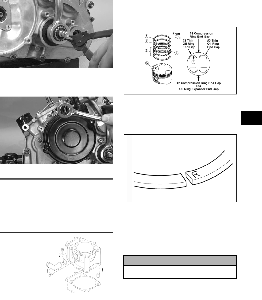
3-245
3
CC044D
28. Place the recoil starter assembly into position on
the left-side cover; then tighten four cap screws
to specifications.
CC039D
Installing Top-Side
Components
A. Piston
B. Cylinder
0732-301
NOTE: If the piston rings were removed, install
them in this sequence.
A. Install ring expander (4) in the bottom groove
of the piston; then install the thin oil rings (3)
over the expander making sure the expander
ends do not overlap.
ATV-1085B
B. Stagger the end gaps of the upper and lower
thin oil rings according to the illustration.
NOTE: Note the direction of the exhaust side of
the piston (5) for correct ring end gap orientation.
ATV-1024
C. Install the compression rings (1 and 2) so the
letter on the top surface of each ring faces the
dome of the piston. Rotate the rings until the
ring end gaps are on directly opposite sides of
the piston (see illustration).
NOTE: The chrome (silver) ring should be
installed in the top position.
1. Install the piston on the connecting rod making
sure there is a circlip on each side and the open
end of the circlip faces upwards.
NOTE: The piston should be installed so the
arrow points toward the exhaust.
KEY
1. Cylinder
2. Stud Bolt
3. Nut
4. Cylinder Gasket
5. Pin
6. Water Hose Union
7. Cap Screw
8. O-Ring
! CAUTION
Incorrect installation of the piston rings will result in
engine damage.
FOR ARCTIC CAT ATV DISCOUNT PARTS CALL 606-678-9623 OR 606-561-4983
www.mymowerparts.com
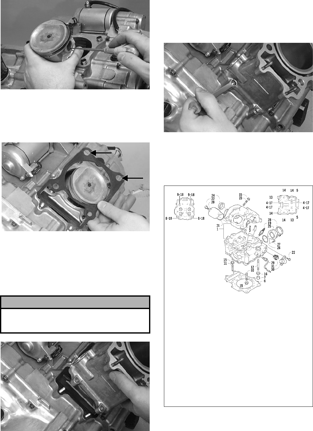
3-246
CC032D
2. Place the two alignment pins into position. Place
the cylinder gasket into position; then place a
piston holder (or suitable substitute) beneath the
piston skirt and square the piston in respect to
the crankcase.
CC025D
3. Lubricate the inside wall of the cylinder; then
using a ring compressor or the fingers, compress
the rings and slide the cylinder over the piston.
Route the cam chain up through the cylinder
cam chain housing; then remove the piston
holder and seat the cylinder firmly on the crank-
case.
CC024D
4. Loosely install the two nuts which secure the
cylinder to the crankcase.
NOTE: The two cylinder-to-crankcase nuts will
be tightened in step 10.
CC023D
5. Install the coolant hose onto the crankcase union
and tighten the clamp.
C. Cylinder Head
D. Valve Cover
0737-755
NOTE: Steps 1-5 in the preceding sub-section
must precede this procedure.
! CAUTION
The cylinder should slide on easily. Do not force the
cylinder or damage to the piston, rings, cylinder, or
crankshaft assembly may occur.
KEY
1. Cylinder Head Assy
2. Valve Guide
3. Dowel Pin
4. Cap Screw
5. Cap Screw
6. Cylinder Head Gasket
7. Dowel Pin
8. Cap Screw
9. Cap Screw
10. Stud Bolt
11. Stud Bolt
12. Stud Bolt
13. Cap Screw
14. Cap Screw
15. Nut
16. Nut
17. Gasket
18. Head Nut Gasket
19. Spark Plug
20. Inspection Cap
21. O-Ring
22. Cap Screw
23. Stud Bolt
24. Cylinder Head Plug
25. Intake Pipe Assy
26. O-Ring
27. Cap Screw
28. Clamp
29. Water Temperature Switch
Assy
30. Thermostat Cover
31. Thermostat
*Frost Plug
*Not Illustrated
FOR ARCTIC CAT ATV DISCOUNT PARTS CALL 606-678-9623 OR 606-561-4983
www.mymowerparts.com
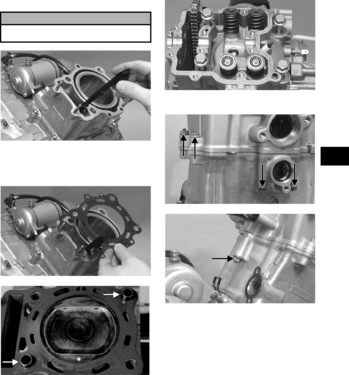
3-247
3
6. Place the chain guide into the cylinder.
CC022D
7. Place the head gasket into position on the cylin-
der. Place the alignment pins into position; then
place the head assembly into position on the cyl-
inder.
CC020D
CF057A
8. Install the four cylinder head cap screws with
copper washers (note the locations of the differ-
ent-lengthed cap screws). Tighten only until
snug.
CC272D
9. Loosely install the five cylinder head nuts.
CC018D
CC017D
10. In a crisscross pattern, tighten the four cylinder
head cap screws (from step to 3.8 kg-m (27.5
ft-lb); then tighten the 8 mm nut (from step 9) to
2.5 kg-m (18 ft-lb). Using a crisscross pattern,
tighten the four 6 mm nuts (from step 9) to 1.1
kg-m (8 ft-lb). Tighten the two cylinder-to-
crankcase nuts (from step 4) securely.
11. With the timing inspection plug removed and
the chain held tight, rotate the crankshaft until
the piston is at top-dead-center.
12. With the alignment pin installed in the camshaft,
loosely place the cam sprocket (with the
recessed side facing the cam shaft lobes) onto
the camshaft. At this point, do not “seat” the
sprocket onto the shaft.
! CAUTION
Care should be taken that the bottom of the chain
guide is secured in the crankcase boss.
FOR ARCTIC CAT ATV DISCOUNT PARTS CALL 606-678-9623 OR 606-561-4983
www.mymowerparts.com
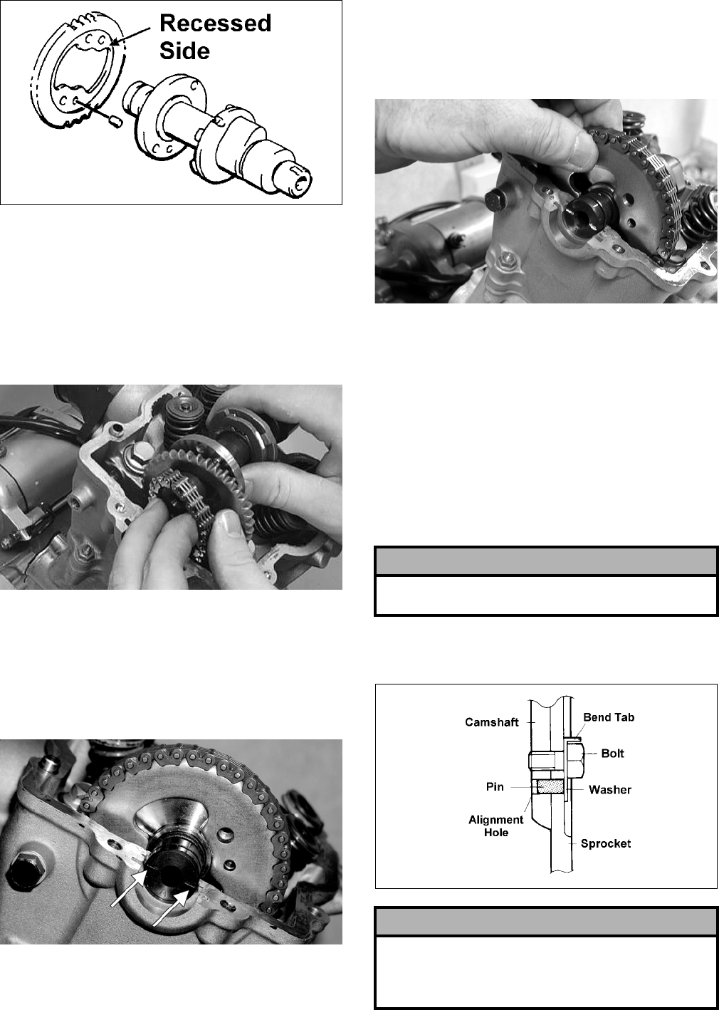
3-248
732-307B
NOTE: At this point, oil the camshaft bearings,
cam lobes, and the three seating journals on the
cylinder.
13. With the cam lobes directed down (toward the
piston), maneuver the camshaft/sprocket assem-
bly through the chain and towards its seating
position; then loop the chain over the sprocket.
CC015D
NOTE: Note the position of the alignment marks
on the end of the camshaft. They must be parallel
with the valve cover mating surface. If rotating the
camshaft is necessary for alignment, do not allow
the chain and sprocket to rotate and be sure the
cam lobes end up in the down position.
CF030A
14. Seat the cam sprocket onto the camshaft making
sure the alignment pin in the camshaft aligns
with the smallest hole in the sprocket; then place
the camshaft/sprocket assembly onto the cylin-
der ensuring the following.
CD463
A. Piston still at top-dead-center.
B. Camshaft lobes directed down (toward the
piston).
C. Camshaft alignment marks parallel to the
valve cover mating surface.
D. Recessed side of the sprocket directed toward
the cam lobes.
E. Camshaft alignment pin and sprocket align-
ment hole (smallest) are aligned.
15. Place the tab-washer onto the sprocket making
sure it covers the pin in the alignment hole.
ATV-1027
! CAUTION
If any of the above factors are not as stated, go back
to step 11 and carefully proceed.
! CAUTION
Care must be taken that the tab-washer is installed
correctly to cover the alignment hole on the
sprocket. If the alignment pin falls out, severe
engine damage will result.
FOR ARCTIC CAT ATV DISCOUNT PARTS CALL 606-678-9623 OR 606-561-4983
www.mymowerparts.com
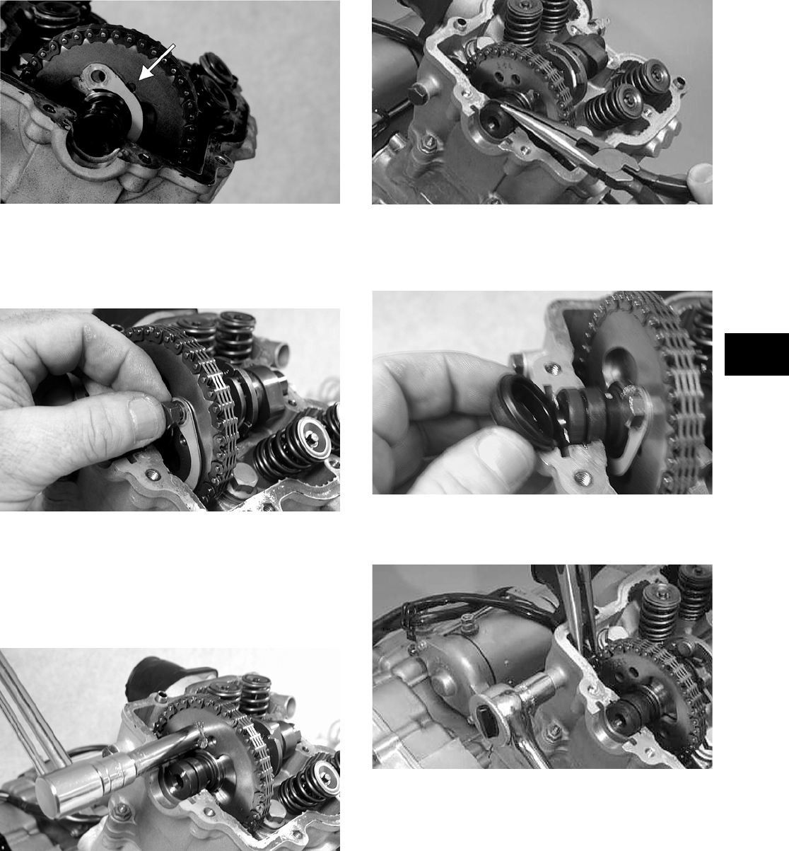
3-249
3
CF013A
16. Install the first cap screw (threads coated with
red Loctite #271) securing the sprocket and
tab-washer to the camshaft. Tighten only until
snug.
CD464
17. Rotate the crankshaft until the second cap screw
securing the sprocket to the camshaft can be
installed; then install the cap screw (threads
coated with red Loctite #271) and tighten to
specifications. Bend the tab to secure the cap
screw.
CD465
18. Rotate the crankshaft until the first cap screw
(from step 16) securing the sprocket to the cam-
shaft can be addressed; then tighten to specifica-
tions. Bend the tab to secure the cap screw.
19. Place the C-ring into position in its groove in the
cylinder.
CC012D
20. Install the cylinder head plug in the cylinder
head with the opening of the plug directed
downward and toward the inside.
CD468
21. Place the cam chain tensioner guide into posi-
tion and secure with the cap screw and washer.
CC014D
22. Remove the cap screw from the end of the chain
tensioner; then using a flat-blade screwdriver,
rotate the adjuster screw inside the tensioner
clockwise until the screw bottoms.
FOR ARCTIC CAT ATV DISCOUNT PARTS CALL 606-678-9623 OR 606-561-4983
www.mymowerparts.com
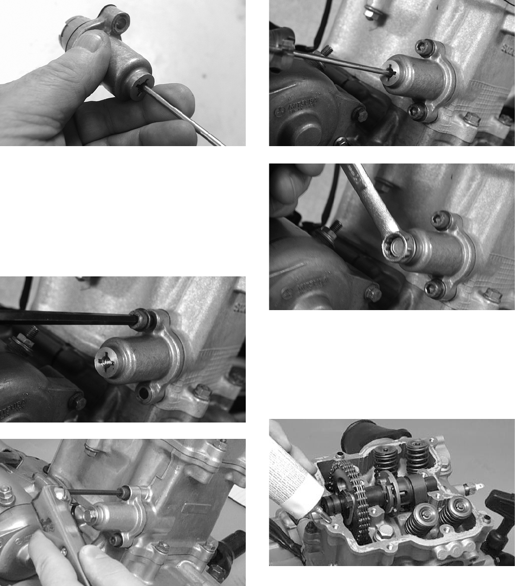
3-250
CD501
NOTE: The adjuster shaft will be drawn into the
tensioner as the adjuster screw is rotated clock-
wise. The adjuster shaft tension will be released in
step 24.
23. Place the chain tensioner adjuster assembly and
gasket into position on the cylinder and secure
with the two Allen-head cap screws.
CD469
CC010D
24. Using a flat-blade screwdriver, rotate the
adjuster screw inside the tensioner counter-
clockwise until all tension is released; then
install the cap screw into the end of the chain
tensioner.
CD470
CD471
25. Loosen the four adjuster screw jam nuts; then
loosen the four adjuster screws on the rocker
arms in the valve cover.
26. Apply a thin coat of Three Bond Sealant (p/n
0636-070) to the mating surfaces of the cylinder
head and valve cover.
CC275D
27. Place the valve cover into position.
NOTE: At this point, the rocker arms and
adjuster screws must not have pressure on them.
28. Install the four top side valve cover cap screws
with rubber washers; then install the remaining
cap screws. Tighten only until snug.
FOR ARCTIC CAT ATV DISCOUNT PARTS CALL 606-678-9623 OR 606-561-4983
www.mymowerparts.com
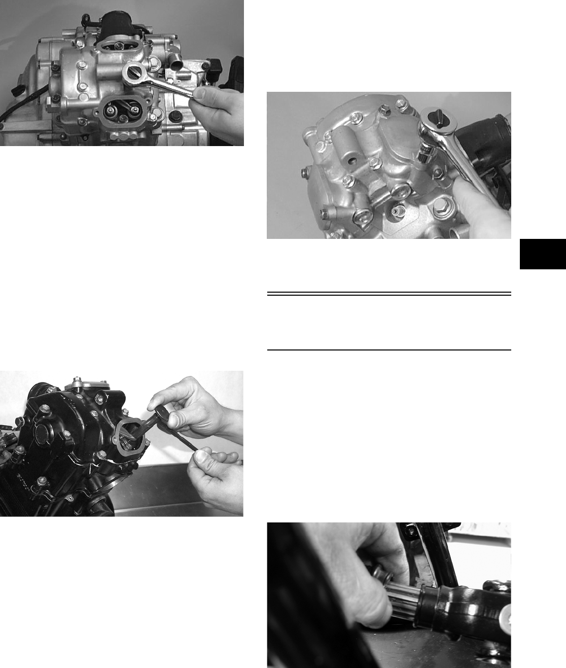
3-251
3
CC003D
29. In a crisscross pattern starting from the center
and working outward, tighten the cap screws
(from step 28) securely.
30. Adjust valve/tappet clearance using the follow-
ing procedure.
NOTE: Use Valve Clearance Adjuster (p/n
0444-078) for this procedure.
A. Turn the engine over until the piston reaches
top dead center on the compression stroke.
B. Place the valve adjuster onto the jam nut
securing the tappet adjuster screw; then rotate
the valve adjuster dial clockwise until the end
is seated in the tappet adjuster screw.
CC528D
C. While holding the valve adjuster dial in
place, use the valve adjuster handle and
loosen the jam nut; then rotate the tappet
adjuster screw clockwise until friction is felt.
D. Align the valve adjuster handle with one of
the marks on the valve adjuster dial.
E. While holding the valve adjuster handle in
place, rotate the valve adjuster dial counter-
clockwise until specified valve/tappet clear-
ance is attained.
NOTE: Rotating the valve adjuster dial counter-
clockwise will open the valve/tappet clearance by
0.05 mm (0.002 in.) per mark.
F. While holding the adjuster dial at the proper
clearance setting, tighten the jam nut securely
with the valve adjuster handle.
31. Place the two tappet covers into position making
sure the proper cap screws are with the proper
cover. Tighten the cap screws securely.
CC001D
32. If removed, install the spark plug and tighten to
specifications.
Installing
Engine/Transmission
NOTE: Arctic Cat recommends that new gaskets
and O-rings be installed whenever servicing the
ATV.
1. From the left side, place the engine/transmission
into the frame; then move it rearward as far as
possible.
2. Raise the rear of the engine enough to engage
the front driveshaft into the splines of the front
drive output yoke; then slide the engine forward
as far as possible.
CD818
3. Raise the rear of the engine and place a block
under it; then install the propeller shaft and out-
put flange into the rear drive coupler.
FOR ARCTIC CAT ATV DISCOUNT PARTS CALL 606-678-9623 OR 606-561-4983
www.mymowerparts.com
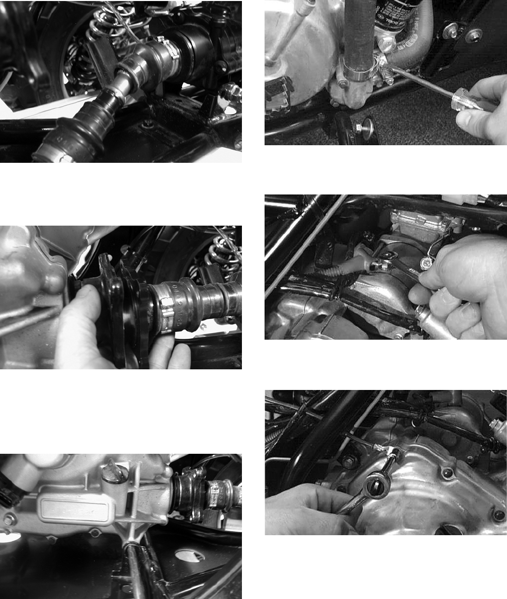
3-252
CD821
4. Remove the block from beneath the engine; then
align the rear drive flanges and secure with four
cap screws. Tighten to specifications.
CD824
5. Install the lower rear engine mounting
through-bolt, spacer, and washer; then install the
lower front engine mounting through-bolt,
spacer, and washer. Secure with the flange nuts.
Tighten to specifications.
CD809
6. Connect the crankcase breather vent hose and
secure with the clamp.
7. Connect the lower coolant hose to the water
pump housing and secure with the clamp.
CC124D
8. Connect the positive cable to the starter motor
and install the protective boot.
AR604D
9. Connect the battery ground (negative) cable to
the crankcase cover.
AR600D
10. Install the coil and secure with two cap screws;
then install the high tension lead on the spark
plug.
FOR ARCTIC CAT ATV DISCOUNT PARTS CALL 606-678-9623 OR 606-561-4983
www.mymowerparts.com
3-253
3
CD814
11. Connect the upper coolant hose to the thermo-
stat housing and secure with the clamp.
CC121D
12. Install the air filter housing; then connect the
crankcase breather and the inlet air duct. Secure
with the clamps.
CD785
CD787
13. Position the carburetor into the intake pipe and
secure with the clamp; then connect the carbure-
tor boot to the air filter housing. Secure with the
clamp.
CD790
CD786
14. Connect the speed sensor connector to the sen-
sor housing.
CD794
15. Install the exhaust pipe and secure with two cap
screws making sure the mounting brackets
engage the frame grommets; then install the
muffler with the springs. Tighten all hardware to
specifications.
FOR ARCTIC CAT ATV DISCOUNT PARTS CALL 606-678-9623 OR 606-561-4983
www.mymowerparts.com
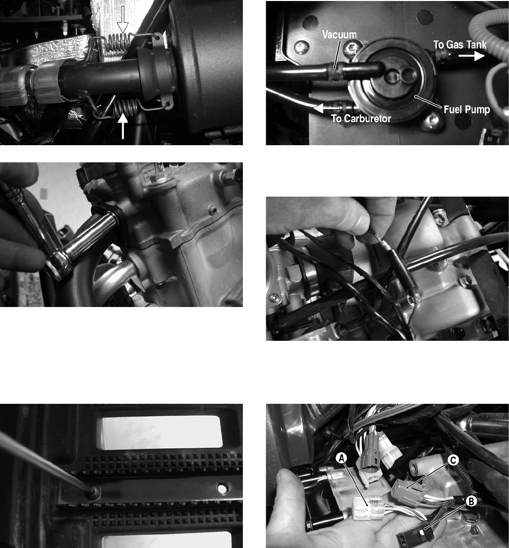
3-254
CF138A
CD803
16. Swing the shift rod back into position on the
engine shift arm; then secure with the E-clip.
17. Place the left-side footwell and foot peg into
position on the footrest. Secure with two cap
screws. Tighten to specifications.
CD782
18. Connect the gas hose to the fuel pump; then con-
nect the vacuum hose. Secure with hose clamps.
CD766A
19. Connect the temperature sensor wire to the main
harness.
CD788
20. Connect the gear position indicator connector
(A), stator connector (B), and the CDI connector
(C) to the main harness.
CD797A
21. Install the front body panel and the front rack
(see Section 8).
22. Place the side panels into position; then install
the reinstallable rivets.
FOR ARCTIC CAT ATV DISCOUNT PARTS CALL 606-678-9623 OR 606-561-4983
www.mymowerparts.com
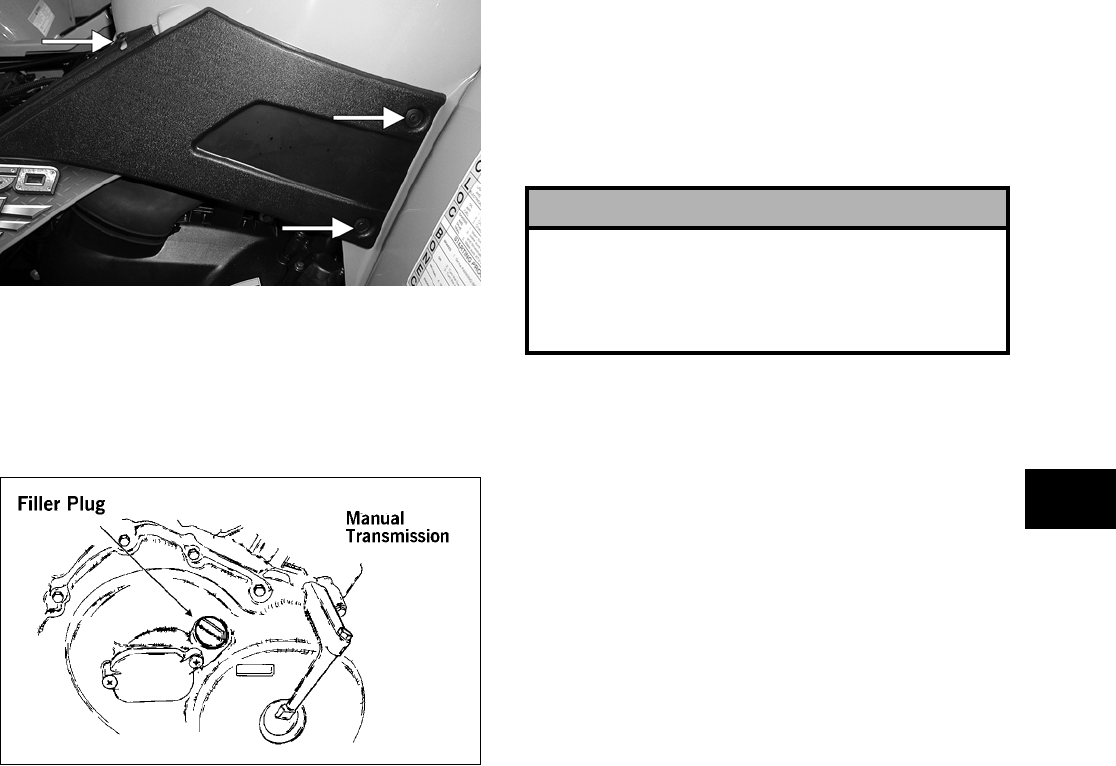
3-255
3
CD683A
23. Install the battery connecting the positive cable
first; then the negative cable.
24. Pour the correct amount of recommended oil
into the engine/transmission filler hole; install
the filler plug.
ATV-0108
25. Pour 2.9 L (3 U.S. qt) of premixed Arctic Cat
Antifreeze into the cooling system. Allow cool-
ant to settle and then fill to the bottom of the
stand pipe in the radiator neck.
26. Install the seat making sure it locks into posi-
tion.
! CAUTION
If the engine had a major overhaul or if any major
part was replaced, proper engine break-in proce-
dures must be followed (see Section 1). If the proper
engine break-in procedures are not followed, severe
engine damage may result.
FOR ARCTIC CAT ATV DISCOUNT PARTS CALL 606-678-9623 OR 606-561-4983
www.mymowerparts.com
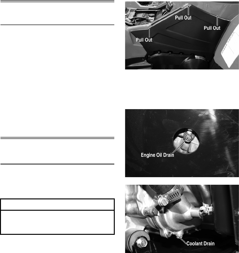
3-256
Table of Contents
(700 EFI)
Removing Engine/Transmission ……………………. 3-256
Top-Side Components……………….…………….…… 3-260
Removing Top-Side Components …….……………. 3-260
Left-Side Components ……………………….………… 3-264
Removing Left-Side Components ….…………….… 3-264
Right-Side Components …………….………….……… 3-268
Removing Right-Side Components…..……………. 3-268
Center Crankcase Components ……………………. 3-271
Separating Crankcase Halves………….……………. 3-271
Disassembling Crankcase Half ……………………… 3-272
Servicing Components………..……………..………… 3-274
Assembling Crankcase Half ………………..………… 3-294
Joining Crankcase Halves……………….………….… 3-296
Installing Right-Side Components…….……………. 3-297
Installing Left-Side Components …………….……… 3-299
Installing Top-Side Components ………………….… 3-303
Installing Engine/Transmission…………….………… 3-307
Removing Engine/
Transmission
Many service procedures can be performed without
removing the engine/transmission from the frame.
Closely observe the note introducing each sub-sec-
tion for this important information.
1. Remove the seat.
2. Remove the negative cable from the battery;
then remove the positive cable.
3. Remove the radiator access cover, steering post
cover, and storage compartment cover assem-
bly; then remove the storage compartment box.
4. Remove the side panels.
CF237A
5. Remove the front rack and front body panel (see
Section 8).
6. Drain the oil from beneath the engine/transmis-
sion; then drain the coolant.
FI005A
FI004A
7. Remove the air filter (see Section 2).
8. Disconnect the primary coil wire; then discon-
nect the ground wire and remove the high ten-
sion wire/spark plug cap from the spark plug.
AT THIS POINT
If the technician’s objective is to service/replace
left-side components, right-side components, and/or
top-side components, the engine/transmission does
not have to be removed from the frame.
FOR ARCTIC CAT ATV DISCOUNT PARTS CALL 606-678-9623 OR 606-561-4983
www.mymowerparts.com
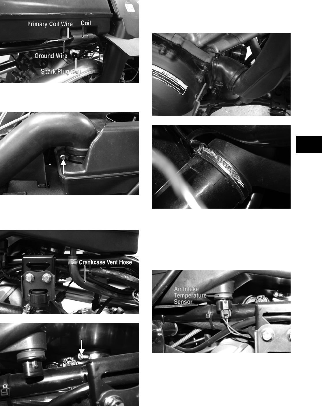
3-257
3
FI066A
9. Loosen the clamp securing the air inlet duct to
the air filter housing.
FI098A
10. Disconnect the crankcase vent hose from the air
filter housing; then loosen the clamp securing
the air filter housing to the throttle body.
FI081A
FI099A
11. Remove the clamp securing the cooling duct
boot to the V-belt housing; then remove the
cooling duct boot from the V-belt housing out-
let.
FI075
FI076
12. Remove the left-side foot peg and footwell (see
Section 8).
13. Disconnect the air intake temperature sensor
connector; then lift the air filter housing off the
frame and slip the air pressure sensor off the
mount. Remove the air filter housing.
FI082A
14. Remove the ISC valve connector, the TPS con-
nector, the coolant temperature sensor connec-
tor, and the fuel injector connector.
FOR ARCTIC CAT ATV DISCOUNT PARTS CALL 606-678-9623 OR 606-561-4983
www.mymowerparts.com
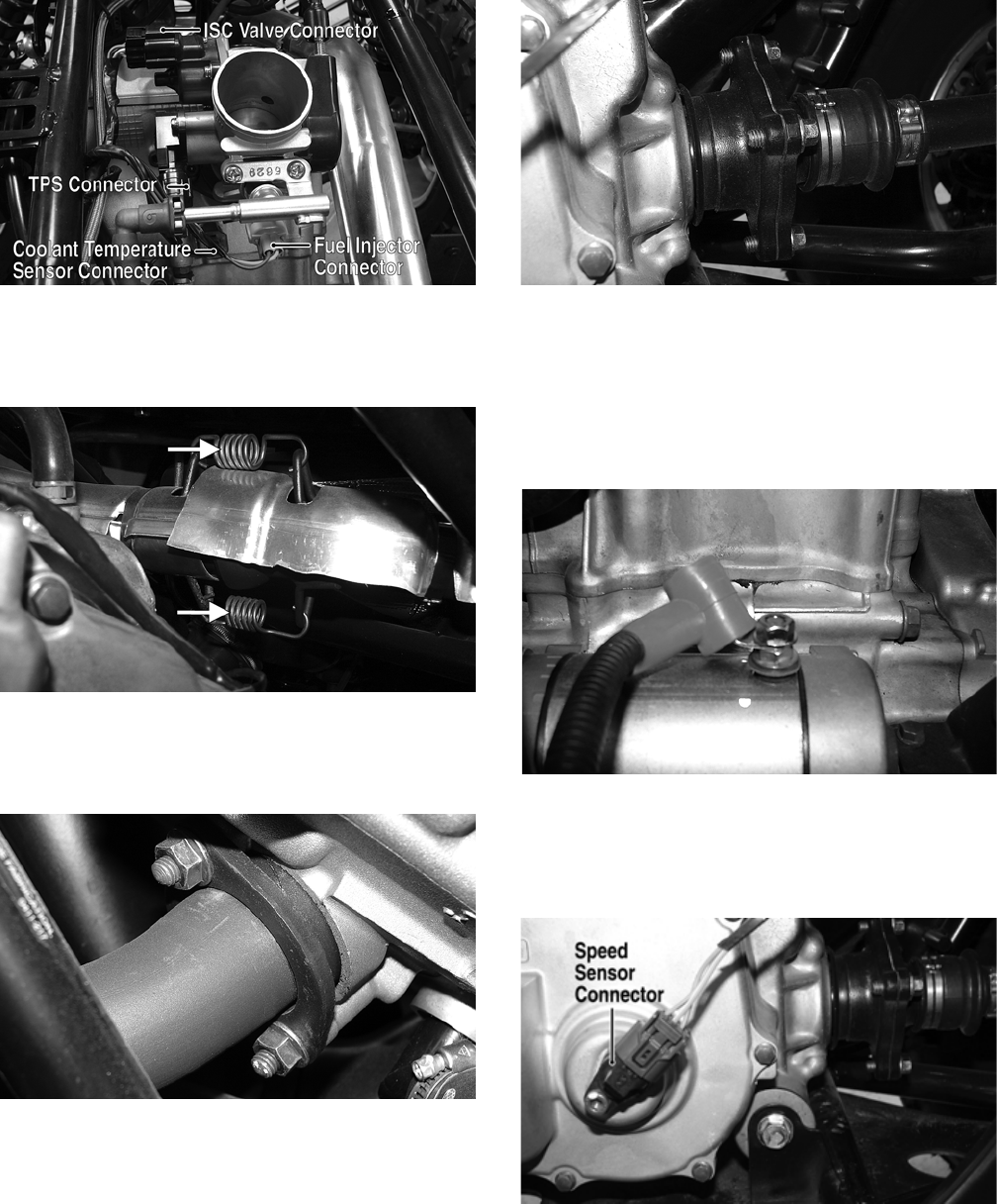
3-258
FI089A
15. Remove the springs securing the muffler to the
exhaust pipe. Account for the two exhaust
springs.
FI097A
16. Remove the two flange nuts securing the
exhaust pipe to the cylinder head; then remove
the pipe.
FI073
17. Remove the two coolant hoses from the engine;
then route the hoses out of the way.
18. Remove the cap screws securing the rear drive-
shaft/output flange to the rear output joint
flange.
FI079
NOTE: It is advisable to lock the brake when
loosening the cap screws securing the rear drive-
shaft.
19. Remove the positive cable from the starter
motor and route it out of the way.
FI094
20. Disconnect the speed sensor connector from the
sensor housing; then mark the shift arm/shift
shaft for installating purposes and remove the
shift arm.
FI078A
FOR ARCTIC CAT ATV DISCOUNT PARTS CALL 606-678-9623 OR 606-561-4983
www.mymowerparts.com
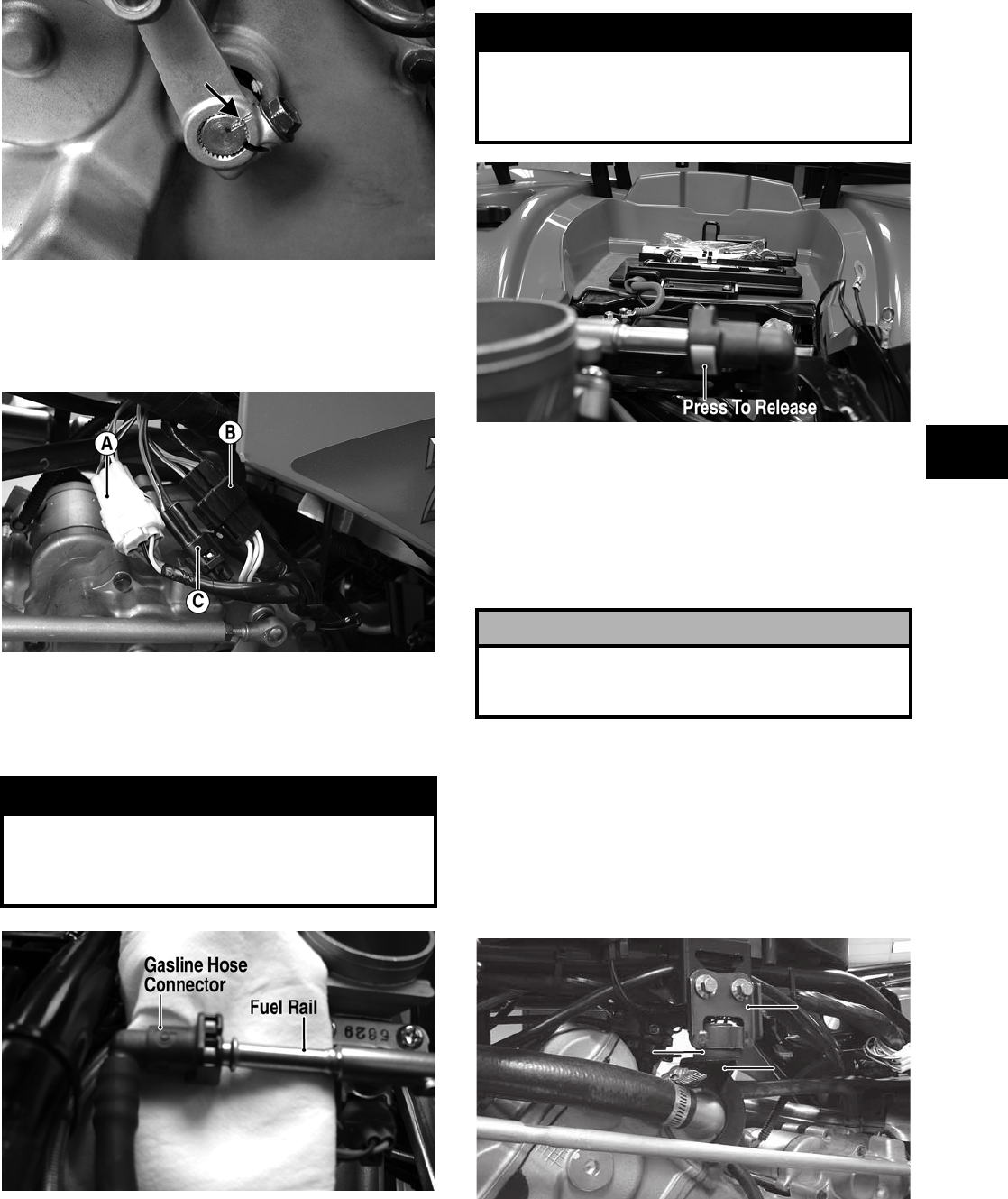
3-259
3
FI085A
21. On the left side, disconnect the gear position
indicator connector (A), stator connector (B),
and the crankshaft position sensor connector
(C).
FI083A
22. Using an absorbent towel to catch any spilled
gas, press the locking tab release on the gasline
hose connector; then slide the gasline hose con-
nector off the fuel rail.
FI092A
FI109A
23. Loosen the clamp securing the throttle body to
the intake pipe; then remove the throttle body
and secure it out of the way.
24. Remove the two cap screws securing the intake
pipe to the cylinder head and remove the intake
pipe. Account for an O-ring.
25. Remove the engine damper stopper from the
frame; then remove the engine damper mount
and damper from the engine.
NOTE: The engine damper mount is secured to
the engine with the thermostat housing cap
screws. Note the position of the bleed valve in the
thermostat for assembling purposes.
FI067A
26. Support the engine/transmission; then remove
the lower front through-bolt.
! WARNING
Whenever working on the fuel system if a gasline
hose is removed from any component, slowly bleed
the pressure from the hose into an absorbent towel
before removing the hose from the component.
! WARNING
Make sure the ignition switch is in the OFF position
and the FUEL fuse is removed from the PDM to pre-
vent inadvertent discharge of gas from the gasline
hose.
! CAUTION
Cover the intake opening to prevent hardware or dirt
from entering the intake or severe engine damage
could occur.
$AMPER
3TOPPER
$AMPER-OUNT
FOR ARCTIC CAT ATV DISCOUNT PARTS CALL 606-678-9623 OR 606-561-4983
www.mymowerparts.com
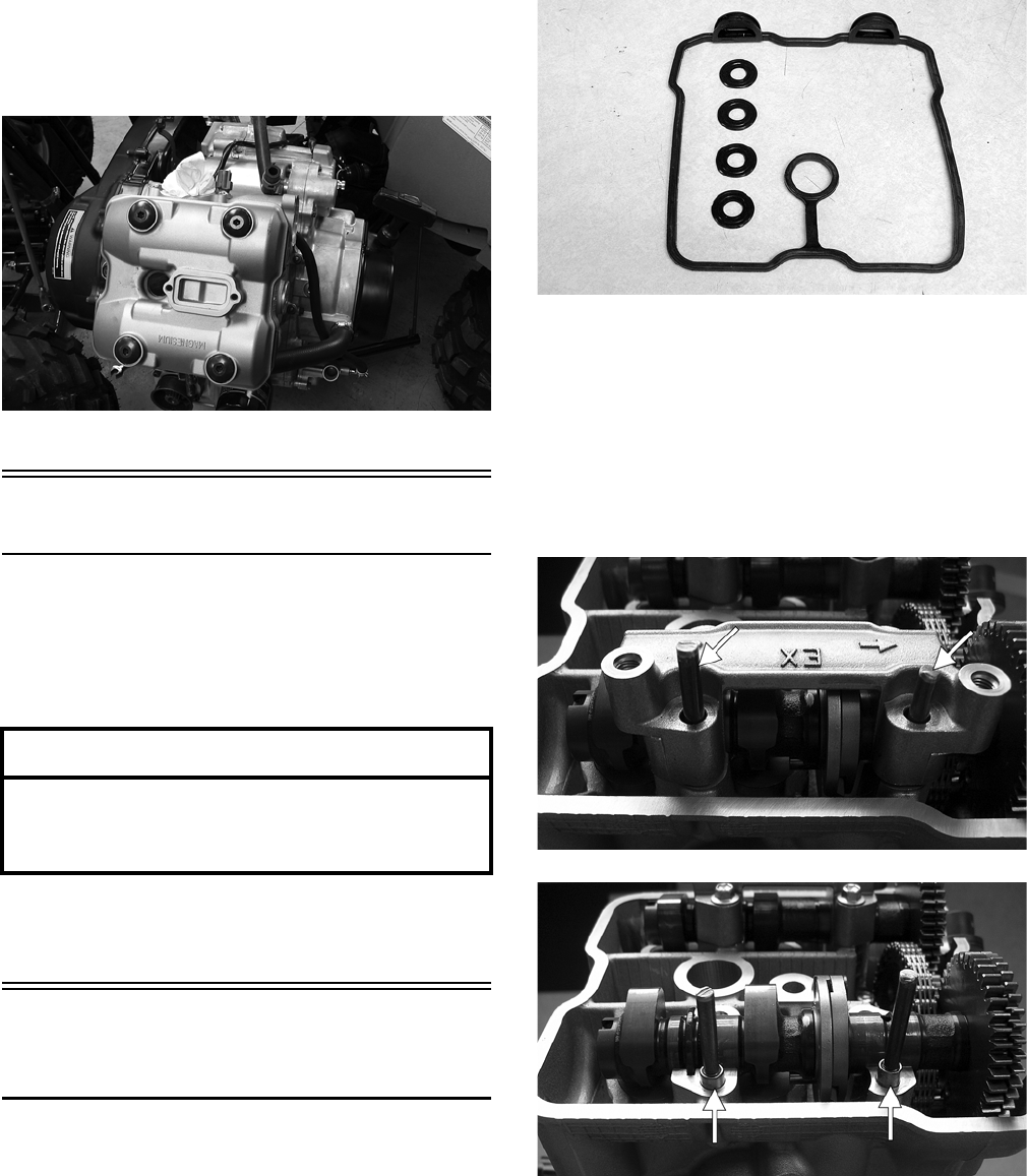
3-260
27. Remove the lower rear through-bolt; then free
the engine from the engine mounting brackets.
28. Lift the front of the engine/transmission far
enough to disengage the front drive spline from
the engine; then remove the engine from the
left-side of the ATV.
FI102
Top-Side Components
NOTE: For efficiency, it is preferable to remove
and disassemble only those components which
need to be addressed and to service only those
components. The technician should use discretion
and sound judgment.
NOTE: The engine/transmission does not have
to removed from the frame for this procedure.
Removing Top-Side
Components
A. Cylinder Head Cover
B. Cylinder Head
NOTE: Remove the spark plug and timing
inspection plug; then using the recoil starter,
rotate the crankshaft to top-dead-center of the
compression stroke. Account for a copper washer
on the timing inspection plug.
1. Remove the cylinder head cover. Account for a
gasket and four seal washers.
FI122
2. Check and record valve tappet clearance for ref-
erence when assembling (see Section 2).
3. Remove the eight cap screws securing the cam-
shaft holders to the cylinder head.
4. Install two alignment studs in the exhaust cam-
shaft holder; then carefully remove the cam
shaft holder. Account for two alignment pins.
FI125A
FI123A
NOTE: Alignment studs can be made by cutting
the heads off two 6 mm x 5 cm cap screws and will
aid in preventing loss of the alignment pins into
the crankcase.
AT THIS POINT
To service any one specific component, only
limited disassembly of components may be
necessary. Note the AT THIS POINT information in
each sub-section.
FOR ARCTIC CAT ATV DISCOUNT PARTS CALL 606-678-9623 OR 606-561-4983
www.mymowerparts.com
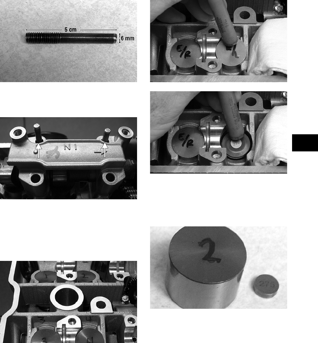
3-261
3
FI155A
5. Remove the exhaust camshaft; then repeat step 4
for the intake camshaft. Account for two align-
ment pins.
FI124A
6. Remove the intake camshaft; then wipe the four
valve tappets clean and using a suitable marker,
number the tappets and mark the corresponding
position on the cylinder head.
NOTE: This will greatly simplify valve clearance
adjustment during assembling.
FI154
7. Using a magnet, withdraw the valve tappets
from the cylinder head taking care to prevent
loose adjusting shims from falling into the
engine.
FI055
FI056
NOTE: The adjustment shims are of different
thickness. Whenever the shims are removed, they
must remain with the corresponding valve tappets
or complete valve adjustment will be required
when assembling.
FI157
8. Remove the cam chain tensioner plug, spring,
guide pin, and O-ring; then remove the cam
chain tensioner body.
FOR ARCTIC CAT ATV DISCOUNT PARTS CALL 606-678-9623 OR 606-561-4983
www.mymowerparts.com
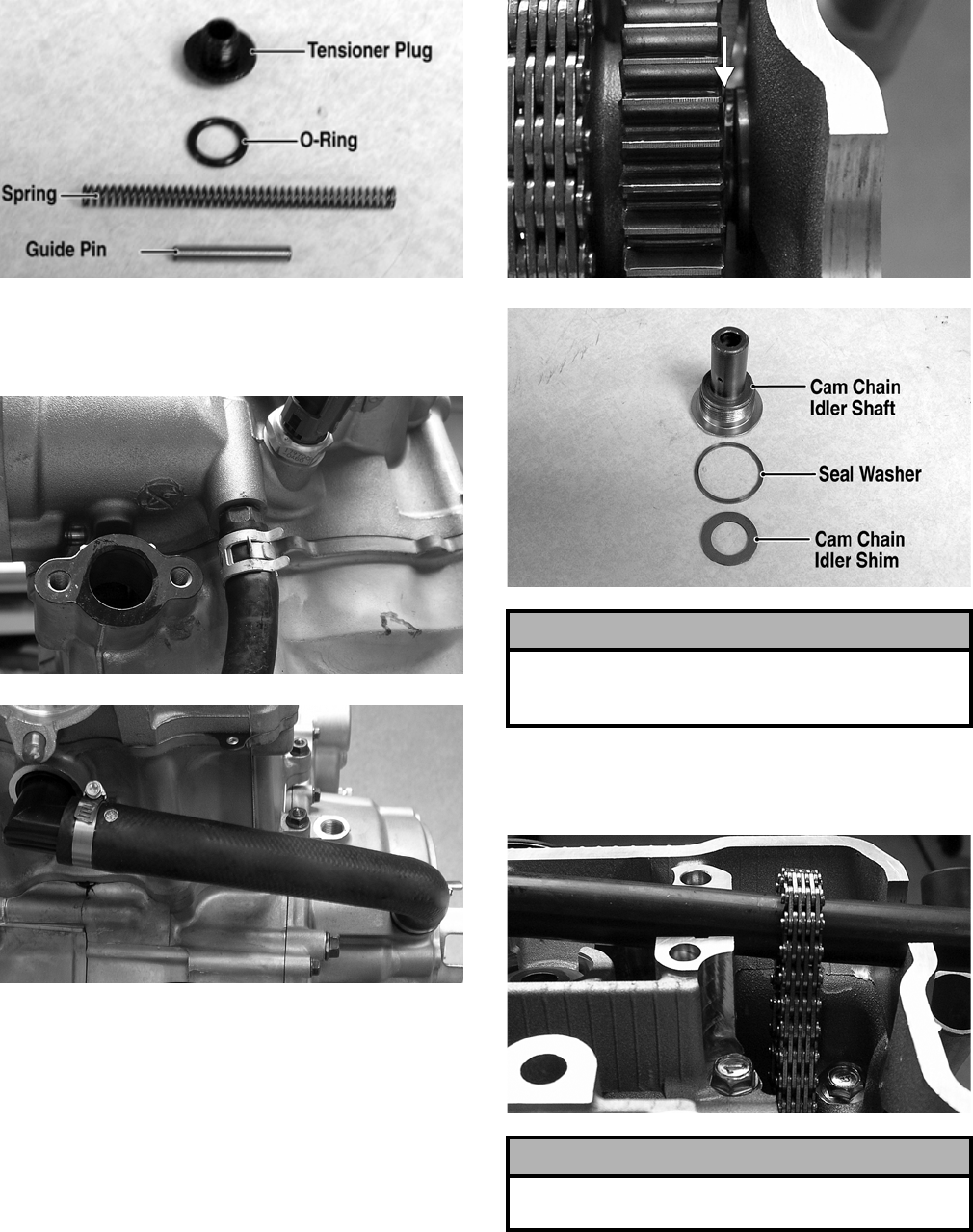
3-262
FI159A
9. Remove the coolant bypass hose from the cylin-
der head fitting; then remove the coolant cross-
over hose.
FI160
FI161
10. Loosen but do not remove the cam chain idler
shaft; then using a suitable flat-blade screw-
driver, hold the cam chain idler shaft shim
against the shoulder of the cam chain idler shaft
and remove the shaft. Account for a copper seal
washer and the cam chain idler shim.
FI162A
FI131A
11. Remove the cam chain idler from the cam chain;
then support the cam chain to prevent it from
dropping into the crankcase.
FI163
12. Remove the cylinder head cap screws (four 6
mm and five 12 mm) noting the location of the
longer and shorter 6 mm cap screws; then
remove the cylinder head. Account for two
alignment pins and one head gasket.
! CAUTION
Failure to hold the cam chain idler shim against the
cam chain idler shaft may result in the shim falling
into the engine resulting in severe engine damage.
! CAUTION
Do not rotate the engine with the cam chain loose or
severe engine damage could occur.
FOR ARCTIC CAT ATV DISCOUNT PARTS CALL 606-678-9623 OR 606-561-4983
www.mymowerparts.com
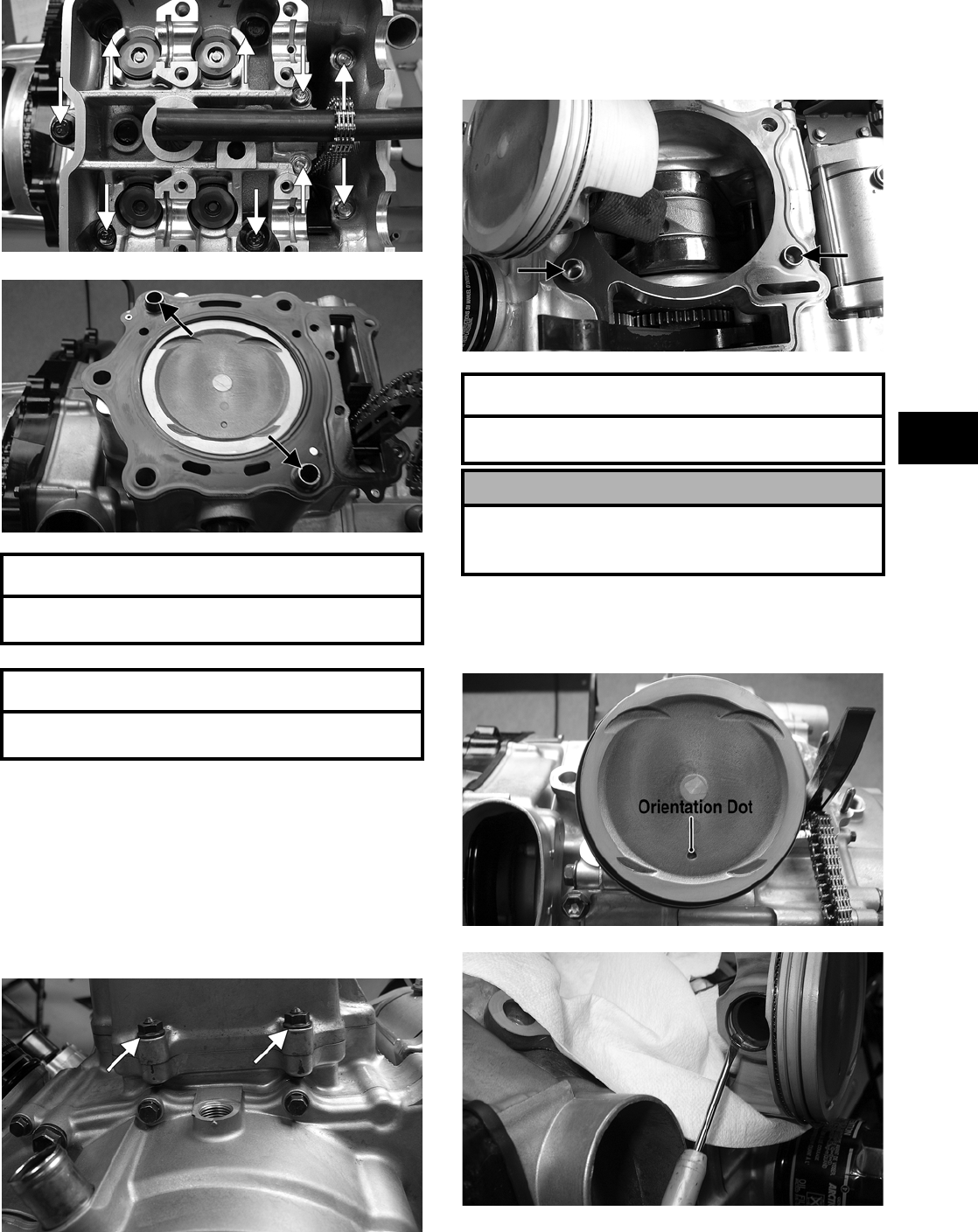
3-263
3
FI133A
FI134A
C. Cylinder
D. Piston
NOTE: Steps 1-12 in the preceding sub-section
must precede this procedure.
13. Remove the cam chain guide; then remove the
two nuts from the cylinder base mounting studs.
FI135A
14. Lift the cylinder off the crankcase taking care
not to allow the piston to drop against the crank-
case. Account for the gasket and two alignment
pins.
FI136A
15. Note the position of the orientation dot on the
piston; then remove the piston pin circlips using
care not to drop the circlip into the crankcase.
FI138A
FI139
16. Remove the piston pin and the piston.
AT THIS POINT
To service valves and cylinder head, see
Servicing Top-Side Components sub-section.
AT THIS POINT
To inspect cam chain guide, see Servicing
Top-Side Components sub-section.
AT THIS POINT
To service cylinder, see Servicing Top-Side
Components sub-section.
! CAUTION
When removing the cylinder, make sure to support
the piston to prevent damage to the crankcase and
piston.
FOR ARCTIC CAT ATV DISCOUNT PARTS CALL 606-678-9623 OR 606-561-4983
www.mymowerparts.com
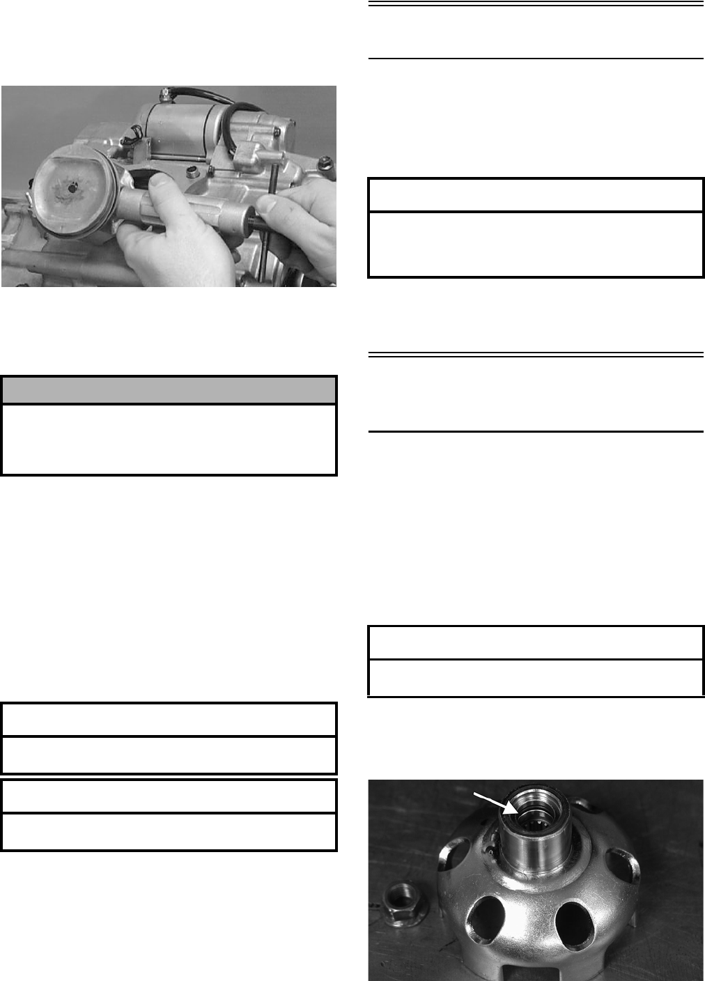
3-264
NOTE: The piston pin is a full-floating type and
should slide out by hand. If the piston pin is stuck,
use Piston Pin Puller (p/n 0644-328) to remove the
piston pin.
CC033D
NOTE: Support the connecting rod with rubber
bands to avoid damaging the rod or install the
Connecting Rod Holder (p/n 0444-006).
NOTE: If the existing rings will not be replaced
with new rings, note the location of each ring for
proper installation. When replacing with new rings,
replace as a complete set only. If the piston rings
must be removed, remove them in this sequence.
A. Starting with the top ring, slide one end of the
ring out of the ring-groove.
B. Remove each ring by working it toward the
dome of the piston while rotating it out of the
groove.
Left-Side Components
NOTE: For efficiency, it is preferable to remove
and disassemble only those components which
need to be addressed and to service only those
components. The technician should use discretion
and sound judgment.
NOTE: The engine/transmission does not have
to be removed from the frame for this procedure.
Removing Left-Side
Components
A. Recoil Starter
B. Water Pump
C. Cover
D. Rotor/Flywheel
E. Oil Pump
1. Remove the four cap screws securing the recoil
starter assembly to the left-side cover; then
remove the recoil starter. Account for the gasket.
2. Remove the flange nut securing the starter cup
to the crankshaft; then remove the starter cup.
Account for the O-ring inside the cup.
CD925A
! CAUTION
Do not allow the connecting rod to go down inside
the crankcase. If the rod is down inside the crank-
case and the crankshaft is rotated, severe damage
will result.
AT THIS POINT
To service piston, see Servicing Top-Side
Components sub-section.
AT THIS POINT
To service center crankcase components only,
proceed to Removing Left-Side Components.
AT THIS POINT
To service any one specific component, only
limited disassembly of components may be
necessary. Note the AT THIS POINT information in
each sub-section.
AT THIS POINT
To service the recoil starter, see Servicing
Left-Side Components sub-section.
FOR ARCTIC CAT ATV DISCOUNT PARTS CALL 606-678-9623 OR 606-561-4983
www.mymowerparts.com
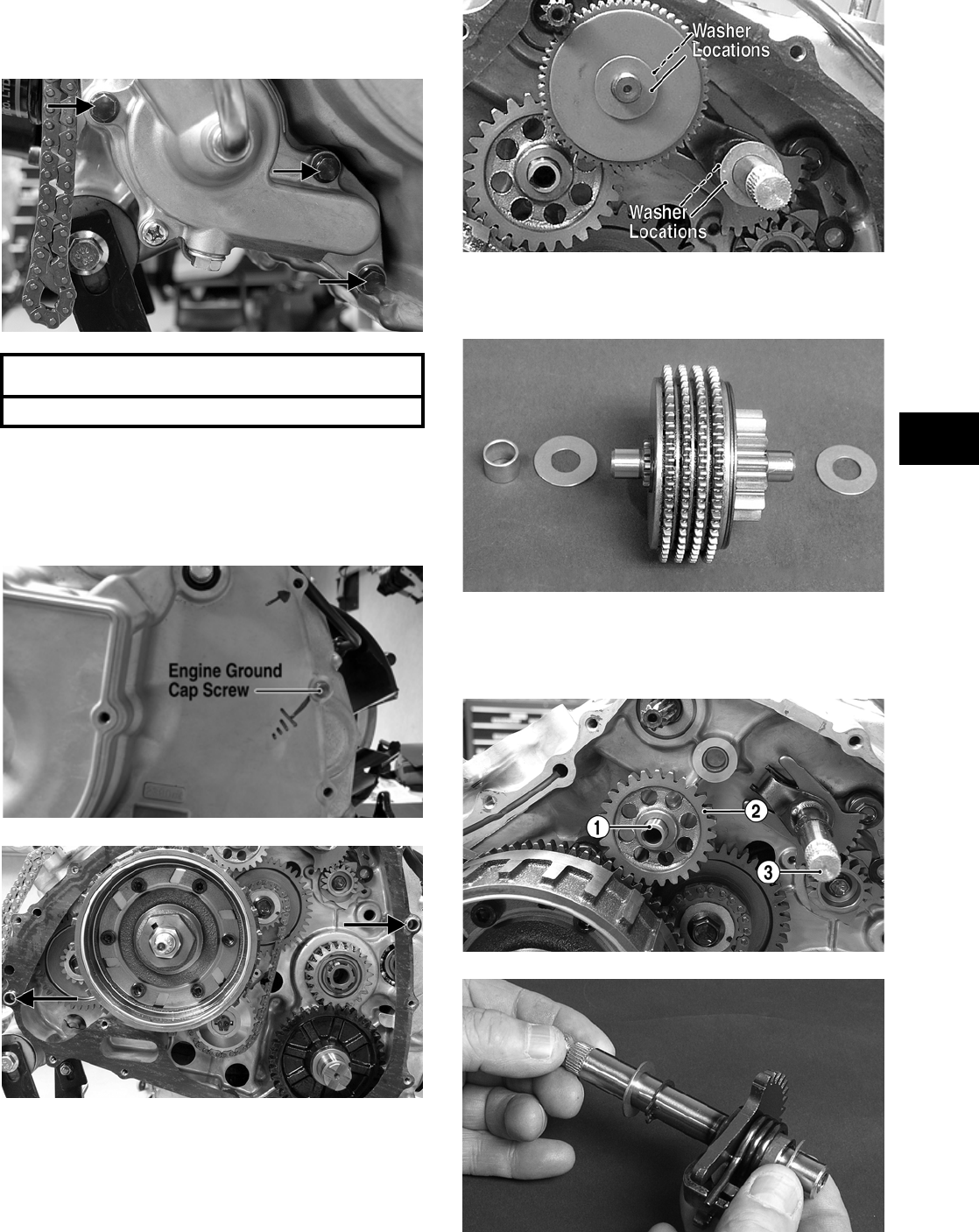
3-265
3
3. Remove the three cap screws securing the water
pump to the engine; then remove the water
pump.
FI141A
4. Remove the cap screws securing the left-side
cover to the crankcase noting the location of the
engine ground cap screw for installing purposes;
then remove the left-side cover. Account for a
gasket and two alignment pins.
FI147A
FI184A
NOTE: Inspect the inside of the left-side cover
for any shaft washers that may have come off with
the cover. Make sure they are returned to their
respective shafts.
FI185A
5. Remove the starter torque limiter. Account for
two washers, one bushing, and the shaft.
FI189
6. Remove the starter idler shaft (1) and the starter
idler gear (2); then remove the shift shaft (3).
Account for two washers on the shift shaft.
FI148A
FI302
AT THIS POINT
To service the water pump, see Section 4.
FOR ARCTIC CAT ATV DISCOUNT PARTS CALL 606-678-9623 OR 606-561-4983
www.mymowerparts.com
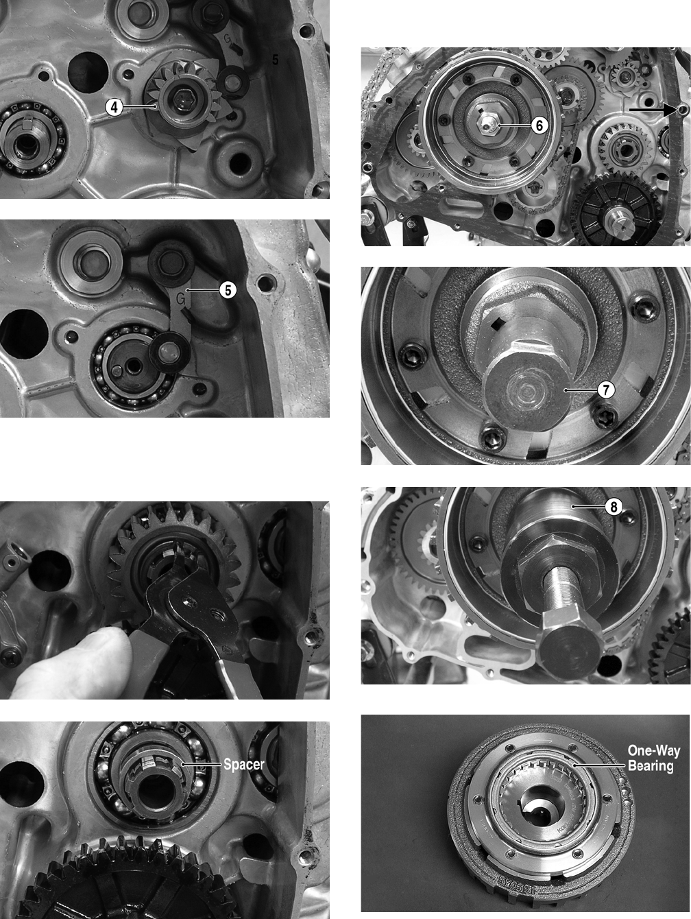
3-266
7. Remove the shift cam driven gear (4); then
remove the cam stopper (5). Account for a spring.
FI311A
FI307A
8. Remove the circlip securing the drive gear on
the countershaft; then remove the drive gear.
Account for a spacer.
FI310
FI309A
9. Remove the rotor/flywheel nut (6); then install
the flywheel protector (7) and Magneto Rotor
Remover (p/n 0444-206) (8) and remove the
rotor/flywheel. Note the orientation of the
one-way bearing.
FI184B
FI191A
FI192A
FI195A
FOR ARCTIC CAT ATV DISCOUNT PARTS CALL 606-678-9623 OR 606-561-4983
www.mymowerparts.com
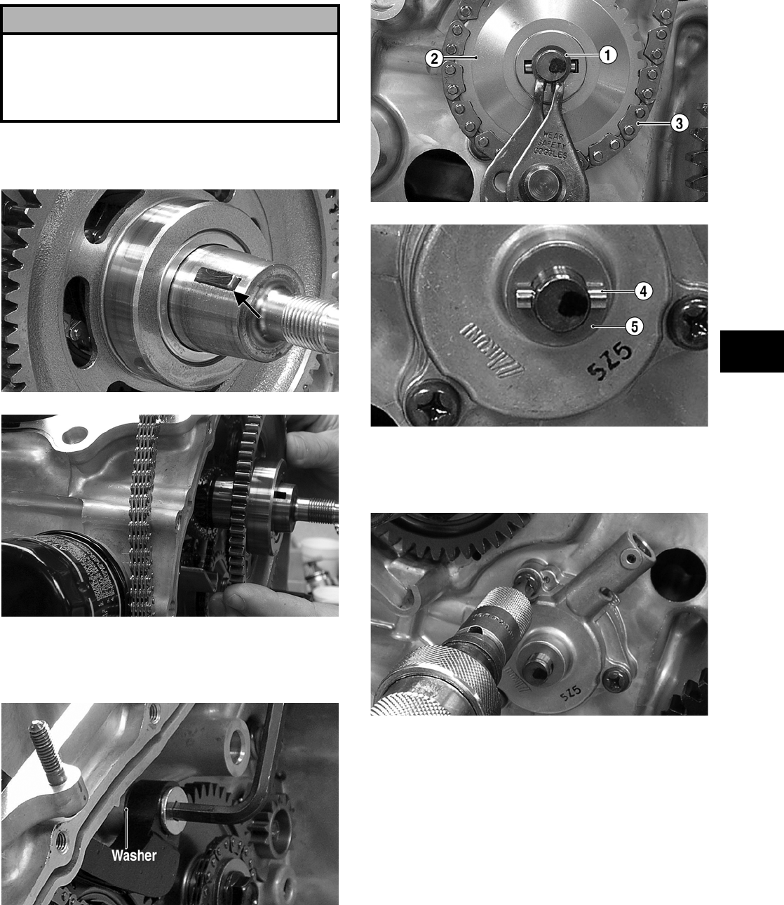
3-267
3
10. Remove the rotor/flywheel key; then remove the
starter driven gear.
FI193A
FI194
11. Remove the pivot bolt from the cam chain ten-
sioner; then remove the cam chain tensioner and
cam chain. Account for a washer.
FI197A
12. Remove the snap ring (1) from the oil pump
shaft; then remove the oil pump driven gear (2)
and drive chain (3). Account for the oil pump
drive pin (4) and washer (5).
FI200A
FI201A
13. Using an impact driver and appropriate Phil-
lips-head bit, remove the three cap screws secur-
ing the oil pump and remove the oil pump.
FI308
NOTE: The oil pump is not a serviceable compo-
nent. Do not disassemble the oil pump. It is avail-
able only as a complete assembly.
14. Remove the cap screws from the crankshaft bal-
ancers; then remove the crankshaft balancer
driven gears. Account for two washers and two
keys.
! CAUTION
Make sure the crankshaft protector is fully installed
on the crankshaft and the rotor/flywheel puller is
turned all the way onto the rotor/flywheel or severe
damage to the crankshaft, rotor/flywheel, or puller
will occur.
FOR ARCTIC CAT ATV DISCOUNT PARTS CALL 606-678-9623 OR 606-561-4983
www.mymowerparts.com
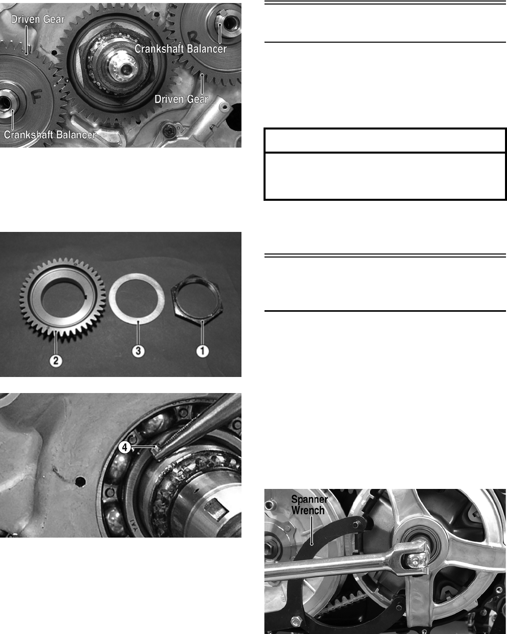
3-268
FI303A
15. Using a 52 mm deep-well socket and a suitable
holding tool, remove the crankshaft balancer
drive gear nut (1) from the crankshaft; then
remove the drive gear (2). Account for a washer
(3) and drive pin (4).
FI305A
FI318A
Right-Side Components
NOTE: For efficiency, it is preferable to remove
and disassemble only those components which
need to be addressed and to service only those
components. The technician should use discretion
and sound judgment.
NOTE: The engine/transmission does not have
to be removed from the frame for this procedure.
Removing Right-Side
Components
A. V-Belt Cover
B. Driven Pulley
C. Clutch Cover
1. Remove the cap screws securing the V-belt
cover; then using a rubber mallet, gently tap on
the cover tabs to loosen the cover. Account for a
gasket.
2. Remove the bearing cap; then using Spanner
Wrench (p/n 0444-153) to hold the drive pulley,
remove the cap screw from the clutch shaft.
FI316A
3. Remove the three cap screws securing the V-belt
bearing housing to the inner V-belt cover; then
remove the housing. Account for two dowel pins
and a spacer.
AT THIS POINT
To service any one specific component, only
limited disassembly of components may be
necessary. Note the AT THIS POINT information in
each sub-section.
FOR ARCTIC CAT ATV DISCOUNT PARTS CALL 606-678-9623 OR 606-561-4983
www.mymowerparts.com
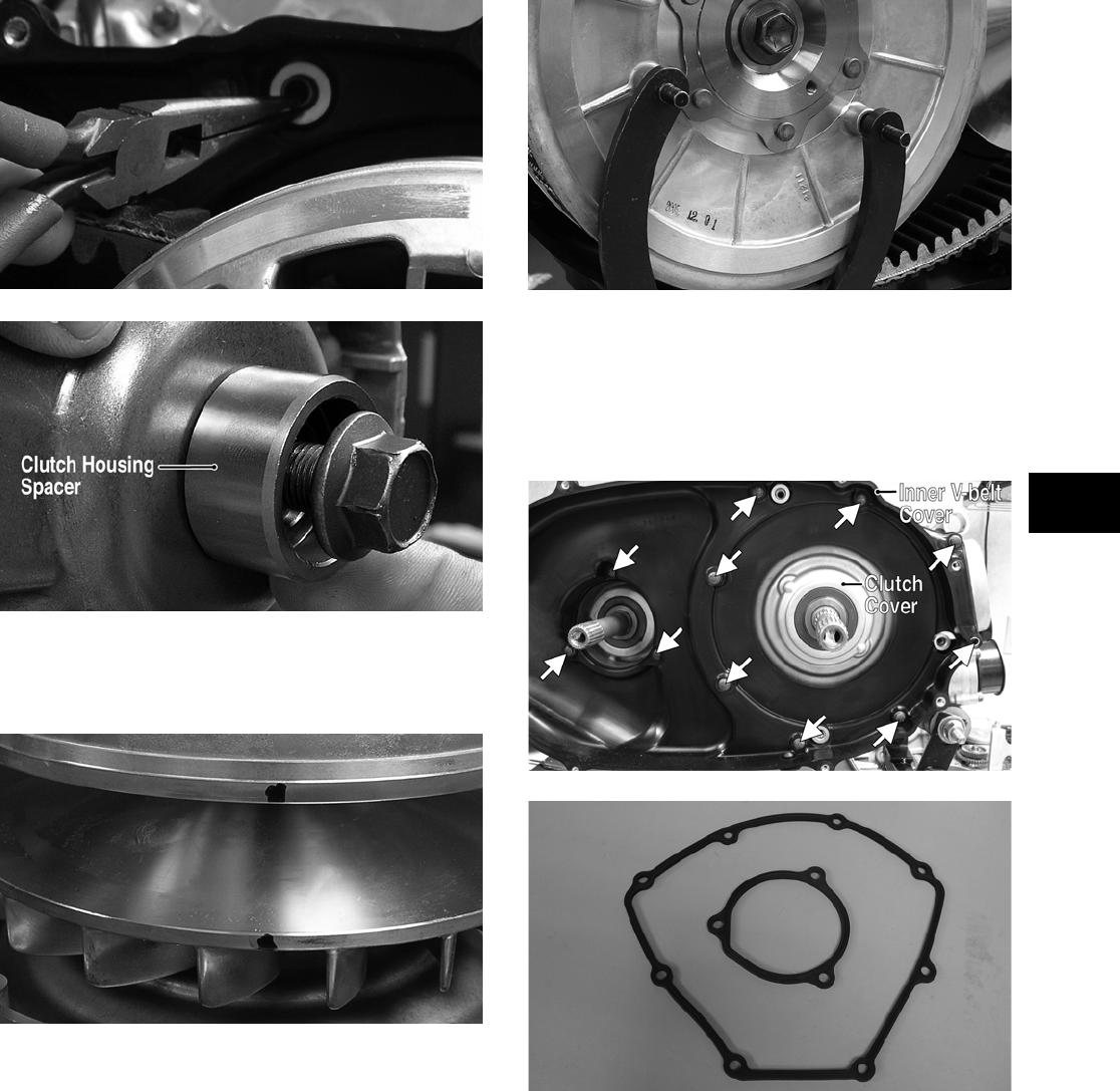
3-269
3
FI315
FI429A
4. Make match marks on the fixed drive face and
the movable drive face; then remove the mov-
able drive face.
FI334
5. Using Spanner Wrench (p/n 0444-153) to hold
the driven pulley, remove the cap screw from the
driveshaft; then remove the driven pulley
assembly and the V-belt.
FI313
6. Remove the fixed drive face and center bushing.
7. Remove the eleven cap screws securing the
inner V-belt cover to the clutch cover; then
remove the inner V-belt cover. Account for two
gaskets.
FI225A
FI226
NOTE: To aid in installing, it is recommended
that the assemblies are kept together and IN
ORDER.
8. Remove the gear shift switch. Account for two
springs and two gear shift switch contacts.
FOR ARCTIC CAT ATV DISCOUNT PARTS CALL 606-678-9623 OR 606-561-4983
www.mymowerparts.com
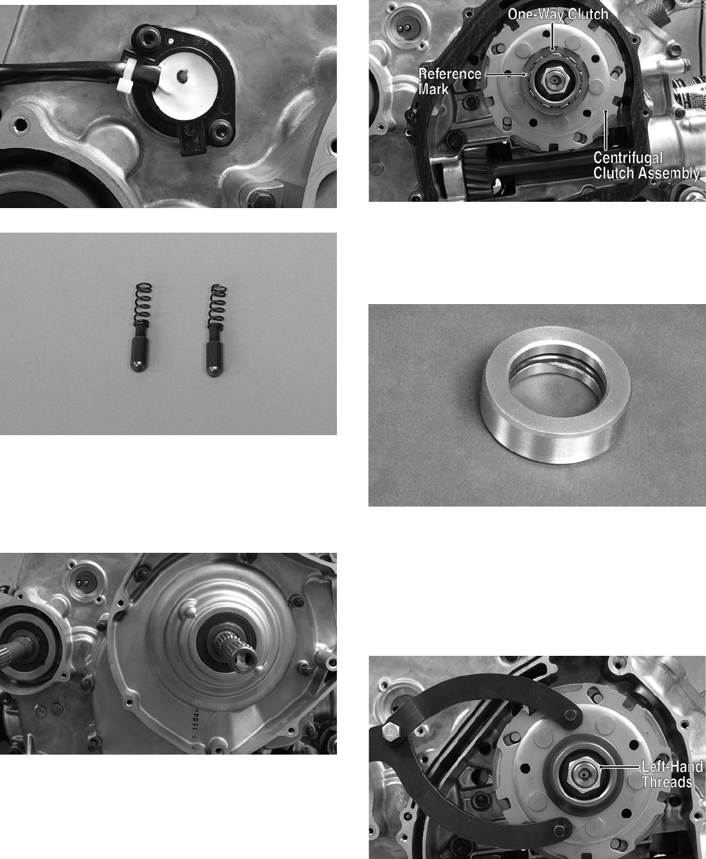
3-270
FI319
FI280
9. Remove the twelve cap screws securing the
clutch cover to the engine case noting the posi-
tions of the two longer cap screws; then remove
the clutch cover. Account for two alignment pins
and a gasket.
FI272
10. Note the reference mark and the word OUT-
SIDE stamped on the cage of the one-way
clutch; then remove the one-way clutch.
FI271A
11. Using a hydraulic press or rubber mallet,
remove the centrifugal clutch housing from the
clutch cover. Account for the primary shaft
spacer with O-ring.
FI344
12. Using Spanner Wrench (p/n 0444-153) to hold
the centrifugal clutch assembly, remove the
clutch retainer nut (left-hand threads); then
remove the centrifugal clutch assembly from the
crankshaft. Account for a concave washer and
note that the concave side is directed toward the
clutch assembly.
FI279A
FOR ARCTIC CAT ATV DISCOUNT PARTS CALL 606-678-9623 OR 606-561-4983
www.mymowerparts.com
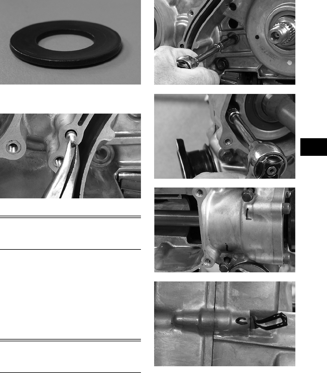
3-271
3
FI336
13. Remove the oil jet from the crankcase. Account
for an O-ring.
FI337
Center Crankcase
Components
NOTE: This procedure cannot be done with the
engine/transmission in the frame. Complete
Removing procedures for Top-Side, Left-Side, and
Right-Side must precede this procedure.
NOTE: For efficiency, it is preferable to remove
and disassemble only those components which
need to be addressed and to service only those
components. The technician should use discretion
and sound judgment.
Separating Crankcase
Halves
1. Remove the thirteen right-side 6 mm cap screws
using a crisscross pattern; then remove the six
right-side 8 mm cap screws. Note the location of
the different-lengthed cap screws and the wire
clip location.
FI274
FI275
FI276
FI277
2. Using the Crankcase Separator/Crankshaft
Remover (p/n 0444-009) and tapping lightly
with a rubber mallet, separate the crankcase
halves. Account for two alignment pins.
FOR ARCTIC CAT ATV DISCOUNT PARTS CALL 606-678-9623 OR 606-561-4983
www.mymowerparts.com
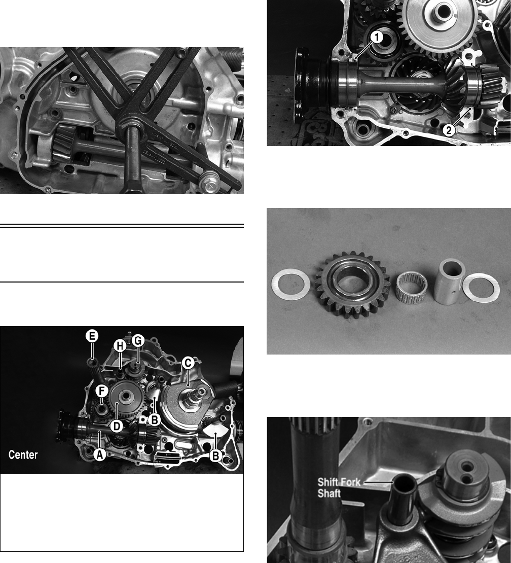
3-272
NOTE: To keep the shaft/gear assemblies intact
for identification, tap the shafts toward the left-side
crankcase half when separating the halves.
FI273
Disassembling
Crankcase Half
NOTE: For steps 1-7, refer to illustration FI235A.
FI235A
NOTE: To aid in assembling, it is recommended
that the assemblies are kept together and IN
ORDER.
1. Remove the secondary driven shaft assembly
(A) noting the location of the bearing locating
pin (1). Account for the bearing C-ring (2).
FI288A
2. Remove the reverse idler gear assembly (F).
Account for two washers, shaft, needle bearing,
and the gear.
FI291
3. Remove the shift fork shaft (H); then remove the
two forks taking note of the direction of the tabs
on the forks for assembling purposes.
FI282A
4. Remove the gear shift camshaft (G) noting the
location of the two holes on the end of the shaft.
KEY
A. Secondary Driven Shaft
Assembly
B. Crank Balancer Assembly
C. Crankshaft
D. Countershaft Assembly
E. Driveshaft
F. Reverse Idler Gear
Assembly
G. Gear Shift Camshaft
H. Shift Fork Shaft with Two
Forks
FOR ARCTIC CAT ATV DISCOUNT PARTS CALL 606-678-9623 OR 606-561-4983
www.mymowerparts.com
3-273
3
FI282B
5. Remove the countershaft assembly (D). Account
for a washer on the end of the countershaft.
FI343
NOTE: Do not disassemble the countershaft
assembly unless necessary. If necessary, see Ser-
vicing Center Crankcase Components sub-sec-
tion.
6. Using a small chisel or screwdriver, unlock the
drive bevel gear nut; then hold the output driven
gear with a suitable holding tool and remove the
drive bevel gear nut.
FI349
7. Using a rubber mallet, tap the output driveshaft
from the bearing. Account for a shim, driven
bevel gear, washer, and nut.
FI407
8. Remove the front and rear crankshaft balancers;
then install the magneto cover on the left crank-
case half.
9. Using Crankcase Separator/Crankshaft Remover
(p/n 0444-009), remove the crankshaft assembly
from the bearing; then remove the magneto
cover.
FI252
! CAUTION
Do not attempt to separate the output driven gear
from the output driveshaft. They are serviced as an
assembly only.
FOR ARCTIC CAT ATV DISCOUNT PARTS CALL 606-678-9623 OR 606-561-4983
www.mymowerparts.com
3-274
Table of Contents
(Servicing Components)
NOTE: Critical engine/transmission specifica-
tions are located at the beginning of this section.
Servicing Top-Side Components ……..……………. 3-274
Cylinder Head/Valve Assembly …….……………. 3-274
Piston Assembly ……….…………….…………….… 3-277
Cylinder Assembly ..…………….…………….……… 3-278
Servicing Left-Side Components .…………….…… 3-281
Recoil Starter ………………………….…………….… 3-281
Inspecting Oil Pump ..…………….…………….…… 3-284
Servicing Right-Side Components ………………… 3-284
Inspecting Centrifugal Clutch Shoe ……………. 3-284
Inspecting Clutch Housing ………………………… 3-284
Inspecting Primary One-Way Drive …………..… 3-285
Driven Pulley Assembly …………………..………… 3-285
Servicing Center Crankcase Components ……… 3-289
Secondary Gears ………………….………….……… 3-289
Crankshaft Assembly ……………….…………….… 3-290
Countershaft …………….…………….…………….… 3-291
Servicing Top-Side
Components
NOTE: Whenever a part is worn excessively,
cracked, or damaged in any way, replacement is
necessary.
CYLINDER HEAD/
VALVE ASSEMBLY
When servicing valve assembly, inspect valve seats,
valve stems, valve faces, and valve stem ends for
pits, burn marks, or other signs of abnormal wear.
NOTE: Whenever a valve is out of tolerance, it
must be replaced.
Cleaning/Inspecting Cylinder Head
1. Using a non-metallic carbon removal tool,
remove any carbon buildup from the combus-
tion chamber being careful not to nick, scrape,
or damage the combustion chamber or the seal-
ing surface.
2. Inspect the spark plug hole for any damaged
threads. Repair damaged threads using a
“heli-coil” insert.
3. Place the cylinder head on the surface plate cov-
ered with #400 grit wet-or-dry sandpaper. Using
light pressure, move the cylinder head in a fig-
ure eight motion. Inspect the sealing surface for
any indication of high spots. A high spot can be
noted by a bright metallic finish. Correct any
high spots before assembly by continuing to
move the cylinder head in a figure eight motion
until a uniform bright metallic finish is attained.
FI358
Measuring Cylinder Head
Distortion
1. Remove any carbon buildup in the combustion
chamber.
2. Lay a straightedge across the cylinder head; then
using a feeler gauge, check the distortion factor
between the head and the straightedge.
3. Maximum distortion must not exceed specifica-
tions.
FI357
! CAUTION
The cylinder head studs must be removed for this
procedure.
! CAUTION
Water or parts-cleaning solvent must be used in
conjunction with the wet-or-dry sandpaper or dam-
age to the sealing surface may result.
FOR ARCTIC CAT ATV DISCOUNT PARTS CALL 606-678-9623 OR 606-561-4983
www.mymowerparts.com
3-275
3
Removing Valves
NOTE: Keep all valves and valve components as
a set. Note the original location of each valve set
for use during installation. Return each valve set to
its original location during installation.
1. Using a valve spring compressor, compress the
valve springs and remove the valve cotters.
Account for an upper spring retainer.
FI331
2. Remove the valve seal and the lower remaining
spring seat. Discard the valve seal.
FI351
NOTE: The valve seals must be replaced.
3. Remove the valve springs; then invert the cylin-
der head and remove the valves.
Measuring Valve Stem Runout
1. Support each valve stem end with the V Blocks
(p/n 0644-022); then check the valve stem
runout using a dial indicator.
FI330
2. Maximum runout must not exceed specifica-
tions.
Measuring Valve Stem
Outside Diameter
1. Using a micrometer, measure the valve stem
outside diameter.
2. Acceptable diameter range (intake valve) must
be within specifications.
3. Acceptable diameter range (exhaust valve) must
be within specifications.
Measuring Valve Face/Seat Width
1. Using a calipers, measure the width of the valve
face.
ATV-1004
2. Acceptable width range must be within specifi-
cations.
Measuring Valve Face Radial
Runout
1. Mount a dial indicator on the surface plate; then
place the valve stem on a set of V blocks.
2. Position the dial indicator contact point on the
outside edge of the valve face; then zero the
indicator.
FOR ARCTIC CAT ATV DISCOUNT PARTS CALL 606-678-9623 OR 606-561-4983
www.mymowerparts.com
3-276
FI328
3. Rotate the valve in the V blocks.
4. Maximum runout must not exceed specifications.
Measuring Valve Stem Deflection
(Wobble Method)
1. Mount a dial indicator and base on the surface
plate; then place the cylinder head on the surface
plate.
2. Install the valve into the cylinder head; then
position the dial indicator contact point against
the outside edge of the valve face. Zero the indi-
cator.
FI323
3. Push the valve from side to side; then from top
to bottom.
4. Maximum “wobble” deflection must not exceed
specifications.
Measuring Valve Guide
(Inside Diameter)
1. Insert a snap gauge 1/2 way down into each
valve guide bore; then remove the gauge and
measure it with a micrometer.
2. Acceptable inside diameter range must be
within specifications.
3. If a valve guide is out of tolerance, it must be
replaced.
Servicing Valves/Valve
Guides/Valve Seats
If valves, valve guides, or valve seats require servic-
ing or replacement, Arctic Cat recommends that the
components be taken to a qualified machine shop
for servicing.
Installing Valves
1. Apply grease to the inside surface of the valve
seals; then place a lower spring seat and valve
guide seal over each valve guide.
FI351
2. Insert each valve into its original valve location.
3. Install the valve springs with the painted end of
the spring facing away from the cylinder head.
NOTE: If the paint is not visible, install the ends
of the springs with the closest wound coils toward
the head.
ATV-1011A
4. Place a spring retainer over the valve springs;
then using the valve spring compressor, com-
press the valve springs and install the valve cot-
ters.
! CAUTION
If any valve is discolored or pitted or if the seating
surface is worn, the valve must be replaced. Do not
attempt to grind a valve or severe engine damage
may occur.
FOR ARCTIC CAT ATV DISCOUNT PARTS CALL 606-678-9623 OR 606-561-4983
www.mymowerparts.com
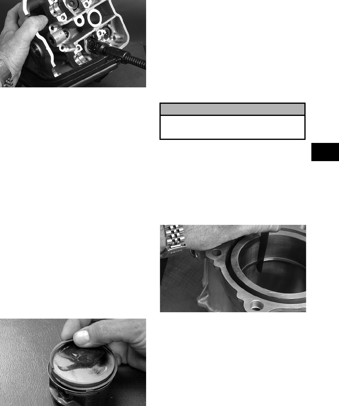
3-277
3
FI331
PISTON ASSEMBLY
NOTE: Whenever a piston, rings, or pin are out
of tolerance, they must be replaced.
Cleaning/Inspecting Piston
1. Using a non-metallic carbon removal tool,
remove any carbon buildup from the dome of
the piston.
2. Inspect the piston for cracks in the piston pin,
dome, and skirt areas.
3. Inspect the piston for seizure marks or scuffing.
Repair with #400 grit wet-or-dry sandpaper and
water or honing oil.
NOTE: If scuffing or seizure marks are too deep
to correct with the sandpaper, replace the piston.
4. Inspect the perimeter of each piston for signs of
excessive “blowby.” Excessive “blowby” indi-
cates worn piston rings or an out-of-round cylin-
der.
Removing Piston Rings
1. Starting with the top ring, slide one end of the
ring out of the ring-groove.
CC400D
2. Remove each ring by working it toward the
dome of the piston while rotating it out of the
groove.
NOTE: If the existing rings will not be replaced
with new ones, note the location of each ring for
proper installation. When installing new rings,
install as a complete set only.
Cleaning/Inspecting Piston
1. Take an old piston ring and snap it into two
pieces; then grind the end of the old ring to a 45°
angle and to a sharp edge.
2. Using the sharpened ring as a tool, clean carbon
from the ring-grooves. Be sure to position the
ring with its tapered side up.
Measuring Piston-Ring End Gap
(Installed)
1. Place each compression ring in the wear portion
of the cylinder. Use the piston to position each
ring squarely in the cylinder.
2. Using a feeler gauge, measure each piston-ring
end gap. Acceptable ring end gap must be
within specifications.
FI327
Measuring Piston Pin (Outside
Diameter) and Piston-Pin Bore
1. Measure the piston pin outside diameter at each
end and in the center. If measurement is not
within specifications, the piston pin must be
replaced.
! CAUTION
Improper cleaning of the ring-grooves by the use of
the wrong type of ring-groove cleaner will result in
severe damage to the piston.
FOR ARCTIC CAT ATV DISCOUNT PARTS CALL 606-678-9623 OR 606-561-4983
www.mymowerparts.com
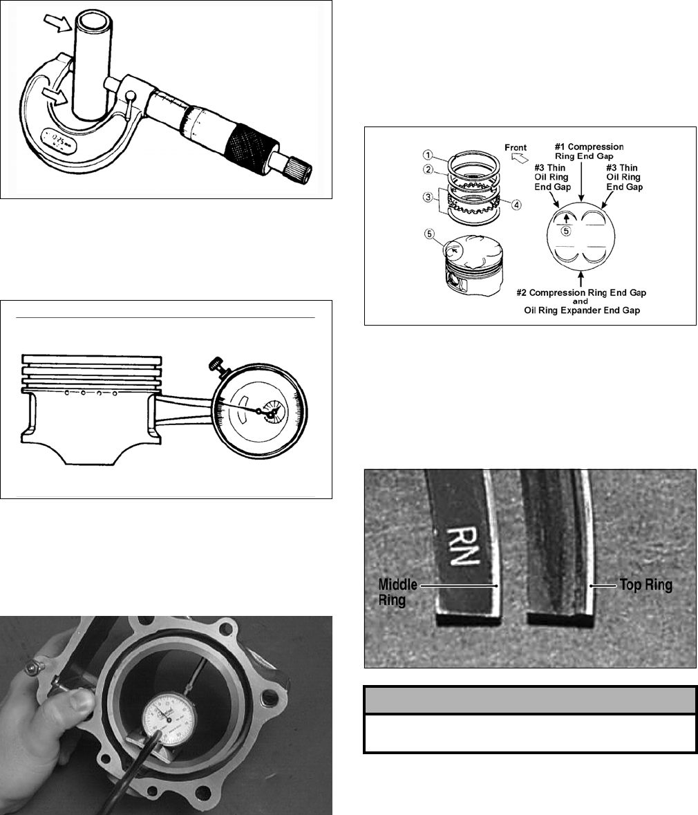
3-278
ATV-1070
2. Insert an inside dial indicator into the piston-pin
bore. The diameter must not exceed specifica-
tions. Take two measurements to ensure accu-
racy.
ATV-1069
Measuring Piston Skirt/
Cylinder Clearance
1. Measure the cylinder front to back in six places.
CC127D
2. Measure the corresponding piston diameter at a
point 15 mm (0.6 in.) above the piston skirt at a
right angle to the piston-pin bore. Subtract this
measurement from the measurement in step 1.
The difference (clearance) must be within speci-
fications.
Installing Piston Rings
Install ring expander (4) in the bottom groove of the
piston; then install the thin oil rings (3) over the
expander making sure the expander ends do not
overlap. Stagger the end gaps of the upper and lower
thin oil rings according to the illustration.
ATV-1085B
NOTE: Note the direction of the exhaust side of
the piston (5) for correct ring end gap orientation.
NOTE: The chrome (L-shaped) ring must be
installed in the top position. The ring marked RN
must be installed in the middle position.
FI168A
CYLINDER ASSEMBLY
NOTE: If the cylinder/cylinder head assembly
cannot be trued, they must be replaced.
Cleaning/Inspecting Cylinder
1. Wash the cylinder in parts-cleaning solvent.
2. Inspect the cylinder for pitting, scoring, scuff-
ing, warpage, and corrosion. If marks are found,
repair the surface using a cylinder hone (see
Honing Cylinder in this sub-section).
! CAUTION
Incorrect installation of the piston rings will result in
engine damage.
FOR ARCTIC CAT ATV DISCOUNT PARTS CALL 606-678-9623 OR 606-561-4983
www.mymowerparts.com
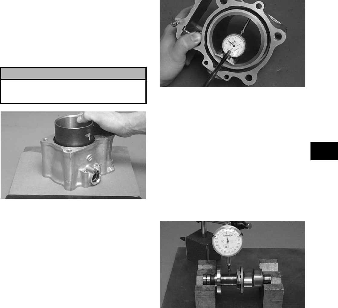
3-279
3
3. Place the cylinder on the surface plate covered
with #400 grit wet-or-dry sandpaper. Using light
pressure, move the cylinder in a figure eight
motion. Inspect the sealing surface for any indi-
cation of high spots. A high spot can be noted by
a bright metallic finish. Correct any high spots
before assembly by continuing to move the cyl-
inder in a figure eight motion until a uniform
bright metallic finish is attained.
CC129D
Inspecting Cam Chain Guide
1. Inspect cam chain guide for cuts, tears, breaks,
or chips.
2. If the chain guide is damaged, it must be
replaced.
Honing Cylinder
1. Using a slide gauge and a dial indicator or a
snap gauge, measure the cylinder bore diameter
in three locations from top to bottom and again
from top to bottom at 90° from the first mea-
surements for a total of six measurements. The
trueness (out-of-roundness) is the difference
between the highest and lowest reading. Maxi-
mum trueness (out-of-roundness) must not
exceed specifications.
CC127D
2. Wash the cylinder in parts-cleaning solvent.
3. Inspect the cylinder for pitting, scoring, scuff-
ing, and corrosion. If marks are found, replace
the cylinder.
4. If any measurement exceeds the limit, replace
the cylinder and piston.
Measuring Camshaft Runout
NOTE: If the camshaft is out of tolerance, it must
be replaced.
1. Place the camshaft on a set of V blocks; then
position the dial indicator contact point against
the shaft and zero the indicator.
CC283D
2. Rotate the camshaft and note runout; maximum
tolerance must not exceed specifications.
! CAUTION
Water or parts-cleaning solvent must be used in
conjunction with the wet-or-dry sandpaper or dam-
age to the sealing surface may result.
FOR ARCTIC CAT ATV DISCOUNT PARTS CALL 606-678-9623 OR 606-561-4983
www.mymowerparts.com
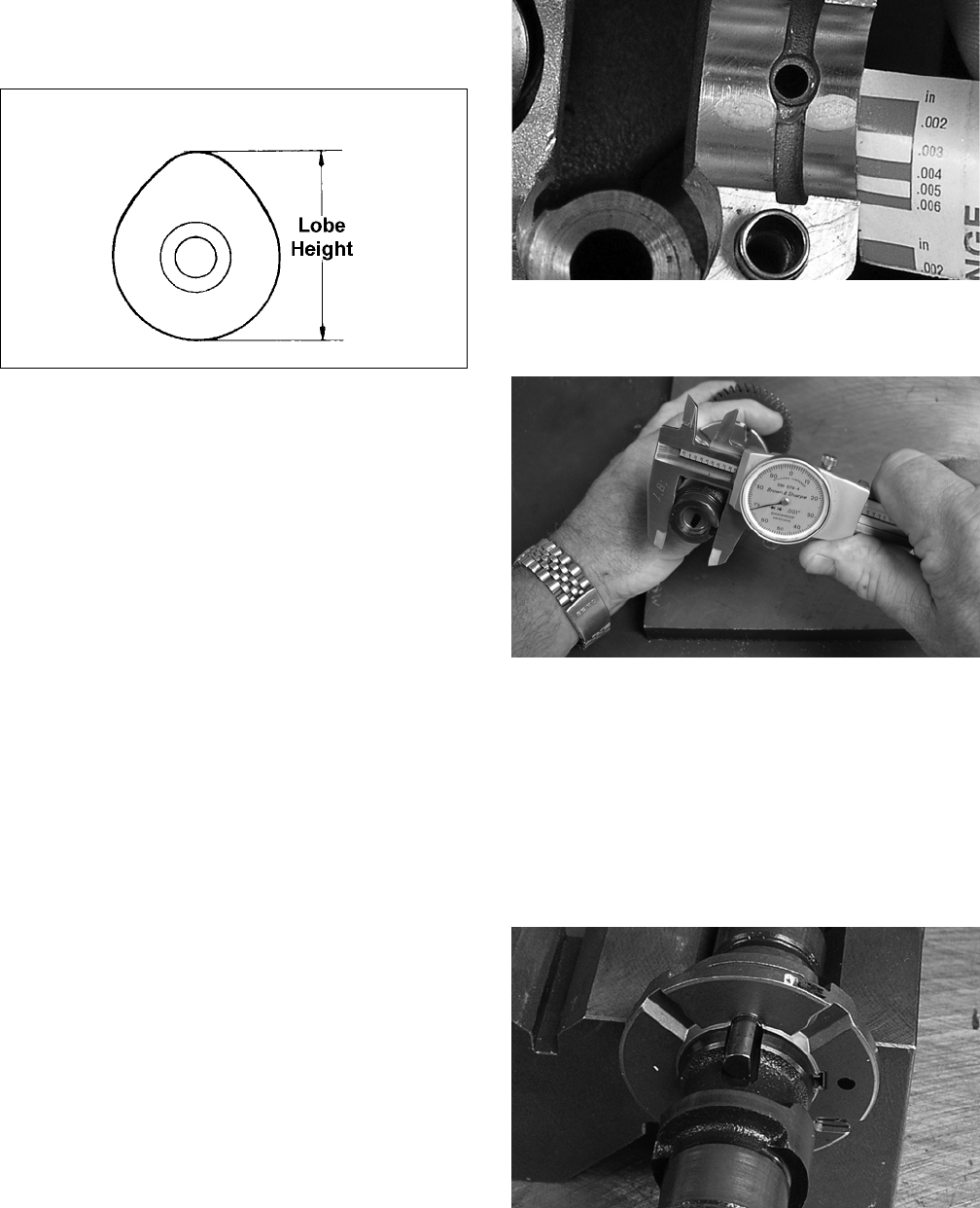
3-280
Measuring Camshaft Lobe Height
1. Using a calipers, measure each cam lobe height.
ATV1013A
2. The lobe heights must not exceed minimum
specifications.
Inspecting Camshaft Bearing
Journal
1. Inspect the bearing journal for scoring, seizure
marks, or pitting.
2. If excessive scoring, seizure marks, or pitting is
found, the cylinder head assembly must be
replaced.
Measuring Camshaft to
Cylinder Head Clearance
1. Place a strip of plasti-gauge in each of the cam-
shaft lands in the cylinder head.
2. Place the camshafts in the cylinder head; then
install the camshaft journal caps and tighten.
NOTE: Do not rotate the camshaft when measur-
ing clearance.
3. Remove the camshaft journal caps; then remove
the camshafts.
4. Match the width of the plasti-gauge with the
chart found on the plasti-gauge packaging to
determine camshaft to cylinder head clearance.
FI444
5. If clearance is excessive, measure the journals of
the camshaft.
FI377
NOTE: If the journals are worn, replace the cam-
shaft; then measure the clearance again. If it is still
out of tolerance, replace the cylinder head.
Inspecting Exhaust Camshaft
Compression Release Assembly
1. Inspect the spring and decompression pin for
damage.
FI411
FOR ARCTIC CAT ATV DISCOUNT PARTS CALL 606-678-9623 OR 606-561-4983
www.mymowerparts.com
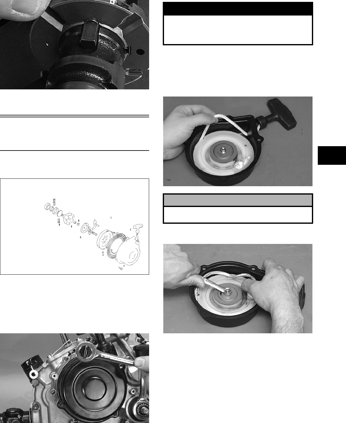
3-281
3
FI412
2. If damaged, the camshaft must be replaced.
Servicing Left-Side
Components
RECOIL STARTER
0737-764
Removing/Disassembling
1. Remove the cap screws securing the recoil
starter assembly to the left-side cover; then
remove the starter.
CC039D
2. Rotate the reel counterclockwise until the notch
of the reel is near the rope guide in the case.
Guide the rope into the notch and slowly allow
the reel to retract until all spiral spring tension is
released.
B600D
3. Remove the nut.
B601D
4. Slowly release the friction plate and lift the plate
with ratchet guide free of the recoil case; then
remove the ratchet guide from the friction plate.
KEY
1. Recoil Starter Assy
2. Rope Assy
3. Spiral Spring
4. Reel
5. Ratchet Assy
6. Nut
7. Cap Screw
8. Nut
9. Starter Cup
10. O-Ring
11. O-Ring
12. Spacer
13. Oil Seal
14. Bearing
! WARNING
During the disassembly procedure, continuous
downward pressure must be exerted on the reel
so it does not accidentally disengage and cause
injury.
! CAUTION
During the disassembly procedure, make sure all
spring tension is released before continuing.
FOR ARCTIC CAT ATV DISCOUNT PARTS CALL 606-678-9623 OR 606-561-4983
www.mymowerparts.com
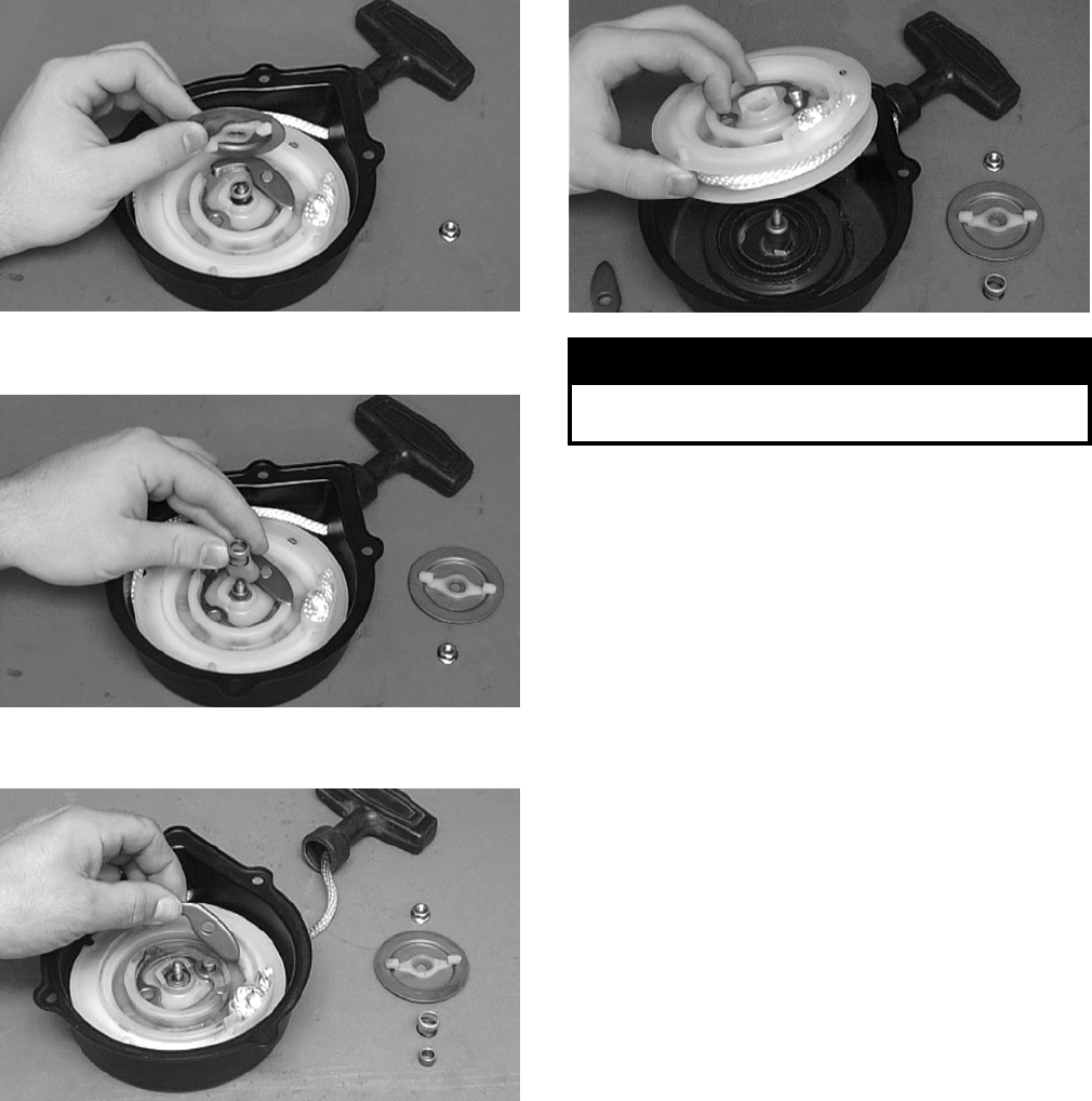
3-282
B602D
5. Remove the spring, collar, and friction spring.
B603D
6. Remove the ratchet and account for the pin.
B604D
7. Carefully lift the reel from the case making sure
the spiral spring does not accidentally disengage
from the case.
B605D
8. Remove the protective cover from the starter
handle and pull the rope out of the handle; then
untie the knot in the rope and remove the han-
dle.
NOTE: Do not remove the spiral spring unless
replacement is necessary. It should be visually
inspected in place to save time. If replacement is
necessary, follow steps 9-10.
9. Remove the spring from the case by lifting the
spring end up and out. Hold the remainder of the
spring with thumbs and alternately release each
thumb to allow the spring to gradually release
from the case.
10. Unwind the rope from the reel and remove the
rope.
Cleaning and Inspecting
NOTE: Whenever a part is worn excessively,
cracked, or damaged in any way, replacement is
necessary.
1. Clean all components.
2. Inspect the springs and ratchet for wear or dam-
age.
3. Inspect the reel and case for cracks or damage.
4. Inspect the shaft for wear, cracks, or damage.
5. Inspect the rope for breaks or fraying.
6. Inspect the spiral spring for cracks, crystalliza-
tion, or abnormal bends.
7. Inspect the handle for damage, cracks, or deteri-
oration.
! WARNING
Care must be taken when lifting the reel free of
the case. Wear safety glasses to avoid injury.
FOR ARCTIC CAT ATV DISCOUNT PARTS CALL 606-678-9623 OR 606-561-4983
www.mymowerparts.com
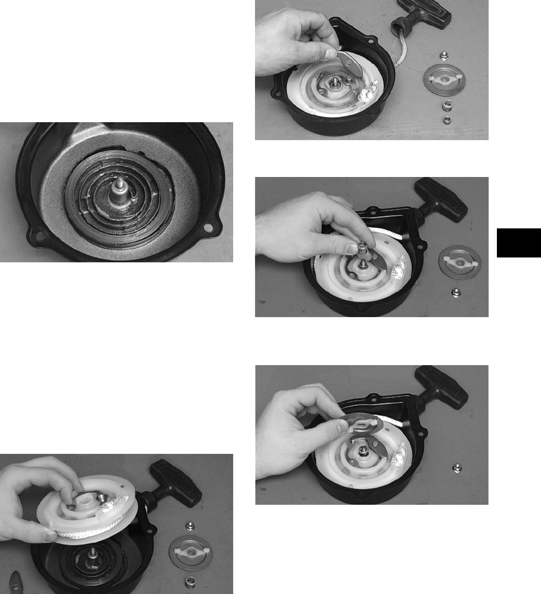
3-283
3
Assembling/Installing
1. If removed, insert the spiral spring into the case
with the outer end of the spring around the
mounting lug in the case; then wind it in a coun-
terclockwise direction until the complete spring
is installed.
NOTE: The spiral spring must seat evenly in the
recoil case.
B606D
2. Insert the rope through the hole in the reel and
tie a knot in the end; then wrap the rope counter—
clockwise around the reel leaving approximately
50 cm (20 in.) of rope free of the reel.
3. Apply low-temperature grease to the spring and
hub.
4. Thread the end of the rope through the guide
hole of the case; then thread the rope through the
handle and secure it with a double knot. Install
the protective cover into the handle.
5. Align the inner hook of the spiral spring with the
notch in the reel.
B605D
6. Install the ratchet making sure the end is prop-
erly installed on the reel.
B604D
7. Install the friction spring and the spring cover.
B603D
8. Install the friction plate with the ratchet guide
fitting into the ratchet.
B602D
9. While pushing down on the reel, install the nut.
Tighten securely.
FOR ARCTIC CAT ATV DISCOUNT PARTS CALL 606-678-9623 OR 606-561-4983
www.mymowerparts.com
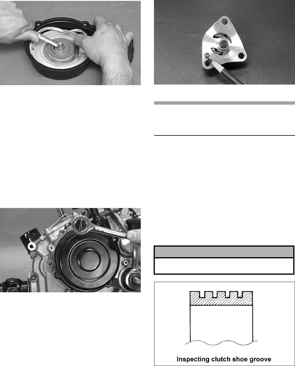
3-284
B601D
10. With the 50 cm (20 in.) of rope exposed, hook
the rope in the notch of the reel.
11. Rotate the reel four turns counterclockwise; then
release the rope from the notch and allow the
rope to retract.
12. Pull the rope out two or three times to check for
correct tension.
NOTE: Increasing the rotations in step 11 will
increase spring tension.
13. Place the recoil starter assembly into position on
the left-side cover; then tighten the cap screws
to specifications.
CC039D
INSPECTING OIL PUMP
1. Inspect the pump for damage.
2. It is inadvisable to remove the screw securing
the pump halves. If the oil pump is damaged, it
must be replaced.
CC446D
Servicing Right-Side
Components
NOTE: Whenever a part is worn excessively,
cracked, damaged in any way, or out of tolerance,
replacement is necessary.
INSPECTING CENTRIFUGAL
CLUTCH SHOE
1. Inspect the clutch shoes for uneven wear, chips,
cracks, or discoloration. If any shoe is damaged,
replace the complete set.
2. Inspect the clutch shoes for wear or damage. If
any shoe is worn to the bottom of the groove,
replace the complete set.
ATV1014
INSPECTING CLUTCH HOUSING
1. Inspect the clutch housing for burns, grooving,
cracks, or uneven wear.
! CAUTION
Always replace the clutch shoes as a complete set
or severe imbalance could occur.
FOR ARCTIC CAT ATV DISCOUNT PARTS CALL 606-678-9623 OR 606-561-4983
www.mymowerparts.com
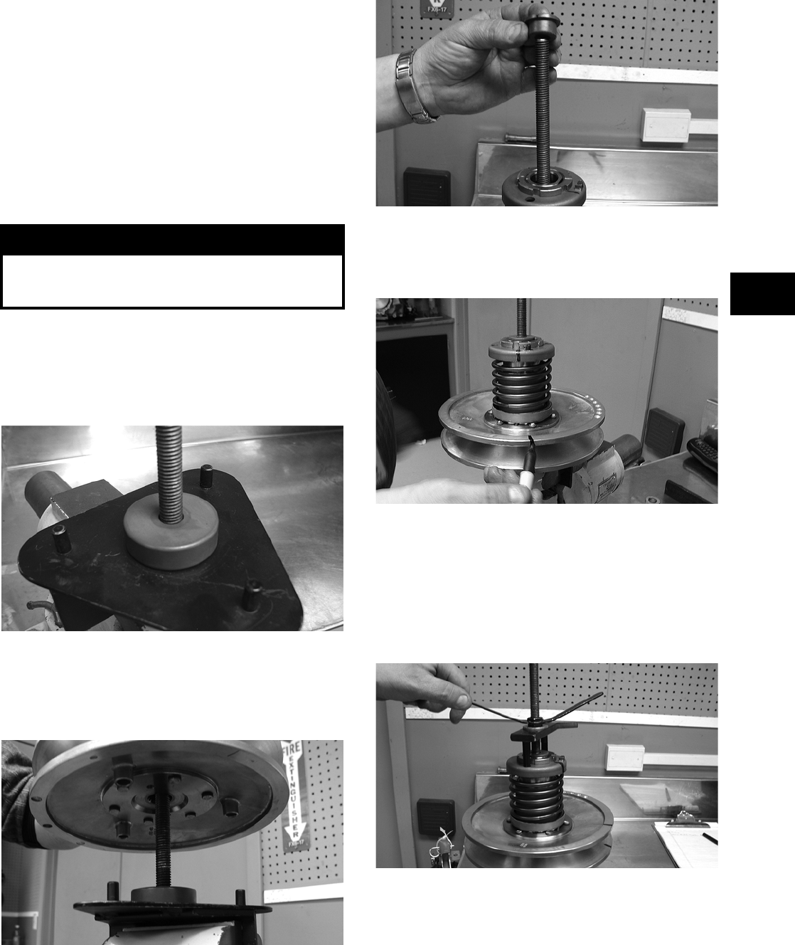
3-285
3
2. If the housing is damaged in any way, the hous-
ing must be replaced.
INSPECTING PRIMARY
ONE-WAY DRIVE
1. Insert the drive into the clutch housing.
2. Rotate the inner race by hand and verify the
inner race rotates only one direction.
3. If the inner race is locked in place or rotates both
directions, the drive assembly must be replaced.
DRIVEN PULLEY ASSEMBLY
Disassembling
1. Secure Driven Pulley Compressor (p/n
0444-121) in a suitable holding fixture such as a
bench vise; then remove the wing nut, holding
handle, flat washer, and pilot bushing leaving
the large spacer on the compressor tool base.
CD047
2. Place the driven pulley assembly onto the com-
pressor tool base engaging the dowel pins into
appropriate holes in the fixed face of the assem-
bly.
CD048
3. Install the pilot bushing with the machined end
directed down; then fit the bushing into the pul-
ley hub.
CD067
4. Using a suitable marking pen, make alignment
marks on the fixed face spring holder and both
pulley faces.
CD049
5. Place the holding handle on the spring holder
fitting the two dowel pins into the spring holder
face; then install a flat washer and the wing nut.
Turn the wing nut down until resistance is felt.
NOTE: Do not use the wing nut to compress the
spring further.
CD050
! WARNING
This procedure involves relaxing a compressed
spring assembly. DO NOT attempt disassembling
without the proper tools.
FOR ARCTIC CAT ATV DISCOUNT PARTS CALL 606-678-9623 OR 606-561-4983
www.mymowerparts.com
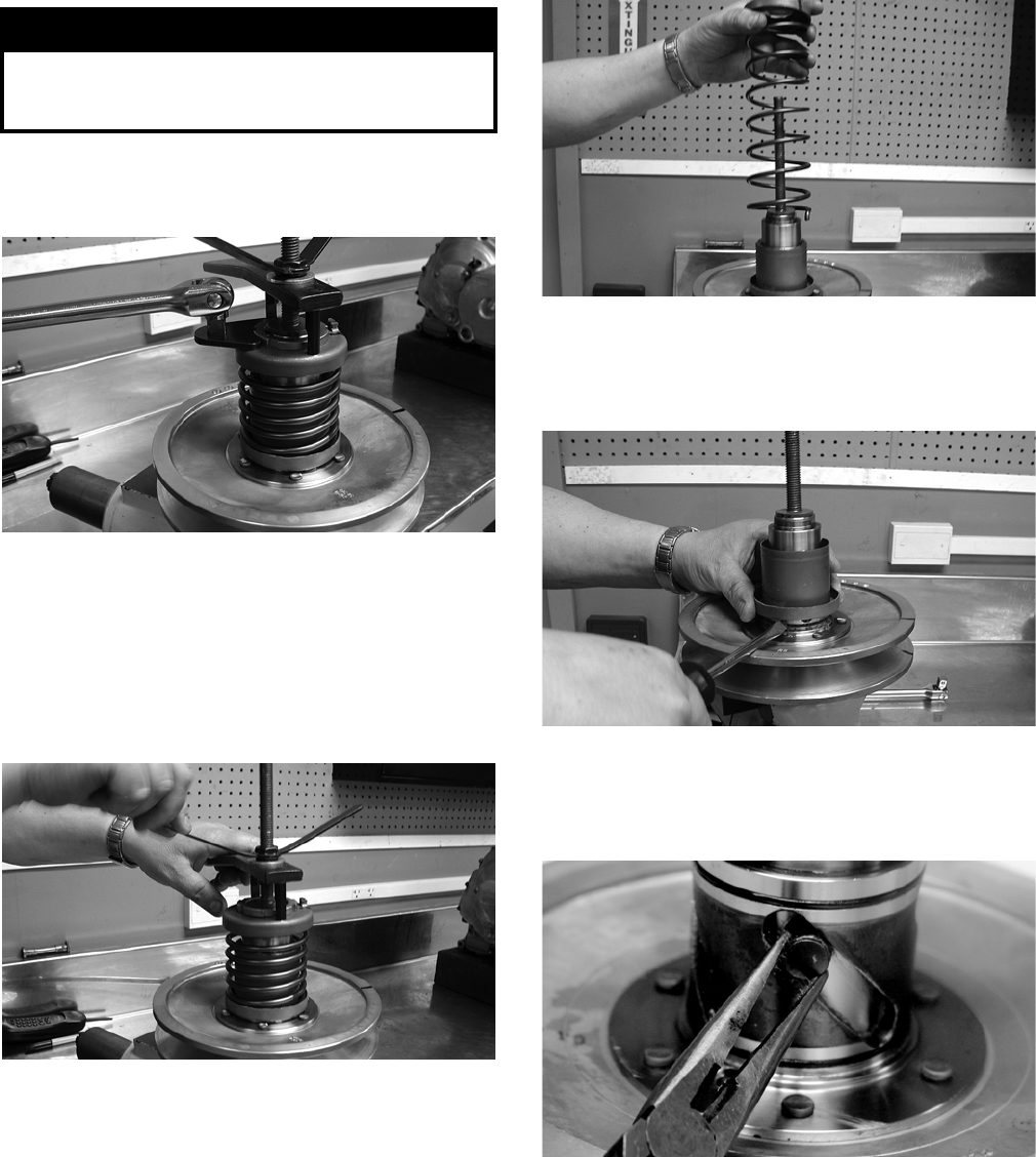
3-286
6. Using a spanner and suitable breaker bar, loosen
the notched-ring nut; then spin the nut free of
the hub.
CD051
7. Firmly hold the handle and slowly turn the wing
nut counterclockwise to relax the spring.
NOTE: There will be a tendency for the handle to
rotate clockwise approximately ¼ turn as the
spring holder clears the flats or hub. This is due to
a slight counterclockwise preload on the spring.
CD052
8. Release the preload slowly; then continue to
relax the spring until the wing nut is flush with
the end of the threads.
9. Firmly holding the spring and spring holder,
remove the wing nut; then remove the spring.
CD053
10. Using a thin pry-bar or screwdriver, work the
movable face sleeve upward and free of the
O-rings; then remove the sleeve.
CD054
11. Remove the four pins and spacers from the cam
slots in the movable face; then remove the mov-
able face.
CF091
! WARNING
The spring assembly is under pressure. Extreme
care must be taken when relaxing the spring. Always
wear safety glasses. Use proper tools only.
FOR ARCTIC CAT ATV DISCOUNT PARTS CALL 606-678-9623 OR 606-561-4983
www.mymowerparts.com
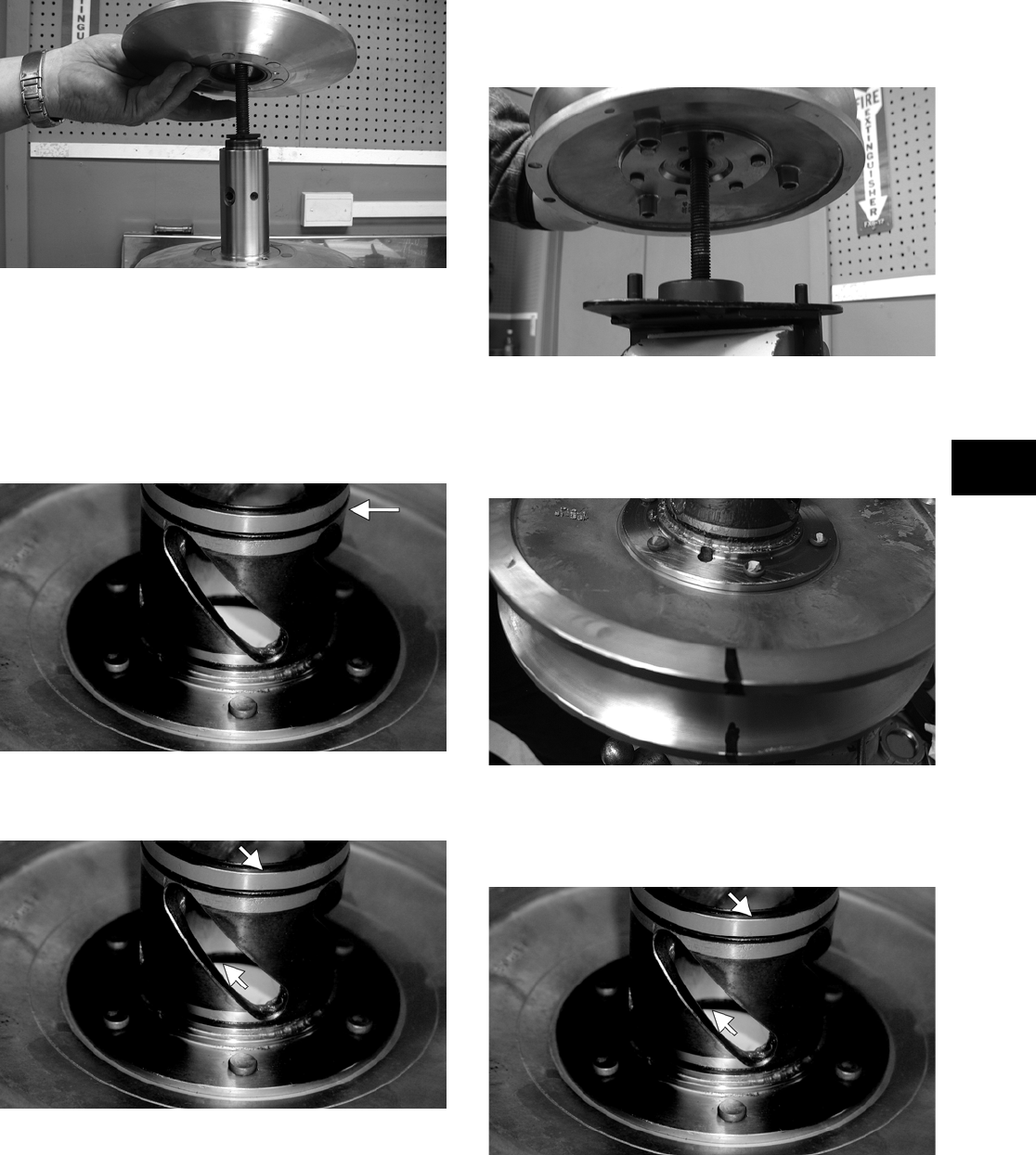
3-287
3
CD056
Inspecting
1. Inspect the pulley faces for wear, galling, or
grooving.
2. Inspect the O-rings on the movable face for
nicks, tears, or swelling.
CF092A
3. Inspect two grease seals in the movable face for
nicks, cuts, or damage.
CF095A
4. Inspect the pins and bushings for wear, flat
spots, looseness, or cracking.
Assembling
1. Place the fixed face of the driven pulley on the
pulley compressor base making sure the dowel
pins are engaged in the appropriate holes in the
pulley face.
NOTE: Make sure the spacer is on the base or
damage to the fixed face will occur when the
spring is compressed.
CD048
2. Apply multi-purpose grease to the O-rings and
grease seals on the movable face; then install on
the fixed face making sure the alignment marks
are properly aligned.
CD060
3. Install the four pins and spacers into the fixed
face hub; then pack the cam slots in the movable
face with multi-purpose grease.
CF095A
4. Install the movable face sleeve aligning the hole
in the spring seat with the spring anchor hole in
the movable face.
FOR ARCTIC CAT ATV DISCOUNT PARTS CALL 606-678-9623 OR 606-561-4983
www.mymowerparts.com
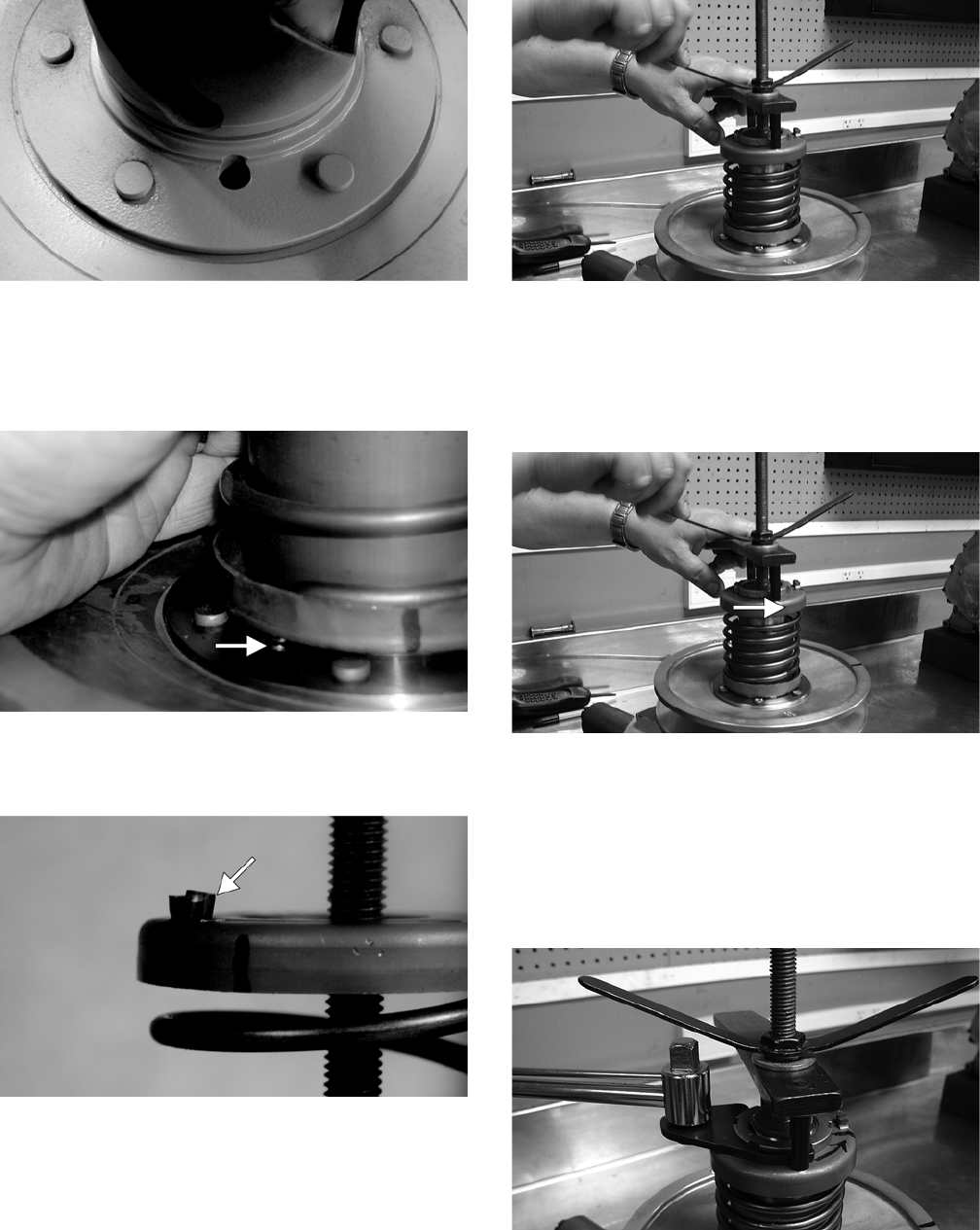
3-288
CF097
5. Install the spring over the hub and movable face
sleeve; then insert the end of the spring through
the sleeve and into the spring anchor hole in the
movable face.
CF089A
6. Place the spring holder on the spring engaging
the spring end with the appropriate anchor hole.
CF087A
7. Assemble the notched-ring nut, spring holding
handle, one flat washer, and the wing nut in
order on the pulley compressor bolt; then thread
the wing nut onto the bolt.
CD052
8. Compress the spring until the spring holder
nears the threads on the fixed face hub; then
using the handle, wind the spring holder coun-
terclockwise to align the flats of the spring
holder and hub.
CD052A
9. Continue compressing the spring while guiding
the spring holder onto the hub. When a slight
resistance is felt, stop turning the wing nut.
10. Install the nut (threads coated with red Loctite
#271); then tighten the nut to specification using
the spanner and a torque wrench.
CD066
11. Remove the wing nut, washer, and holding han-
dle; then remove the driven pulley from the pul-
ley compressor.
FOR ARCTIC CAT ATV DISCOUNT PARTS CALL 606-678-9623 OR 606-561-4983
www.mymowerparts.com
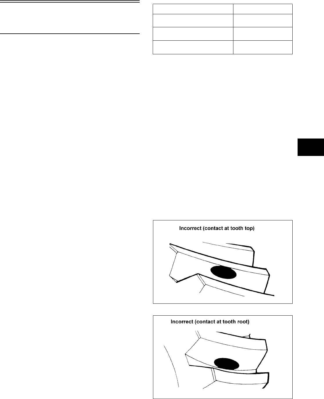
3-289
3
Servicing Center
Crankcase Components
NOTE: Whenever a part is worn excessively,
cracked, damaged in any way, or out of tolerance,
replacement is necessary.
SECONDARY GEARS
NOTE: When checking and correcting secondary
gear backlash and tooth contact, the universal
joint must be secured to the front shaft or false
measurements will occur.
Checking Backlash
NOTE: The rear shaft and bevel gear must be
removed for this procedure. Also, always start with
the original shims on the rear shaft.
1. Place the left-side crankcase cover onto the
left-side crankcase half to prevent runout of the
secondary transmission output shaft.
2. Install the secondary driven output shaft assem-
bly onto the crankcase.
3. Mount the dial indicator so the tip is contacting
a tooth on the secondary driven bevel gear.
4. While rocking the driven bevel gear back and
forth, note the maximum backlash reading on
the gauge.
5. Acceptable backlash range is 0.03-0.15 mm
(0.001-0.006 in.).
Correcting Backlash
NOTE: If backlash measurement is within the
acceptable range, no correction is necessary.
1. If backlash measurement is less than specified,
remove an existing shim, measure it, and install
a new thicker shim.
2. If backlash measurement is more than specified,
remove an existing shim, measure it, and install
a thinner shim.
NOTE: Continue to remove, measure, and install
until backlash measurement is within tolerance.
Note the following chart.
Checking Tooth Contact
NOTE: After correcting backlash of the second-
ary driven bevel gear, it is necessary to check
tooth contact.
1. Remove the secondary driven output shaft
assembly from the left-side crankcase half.
2. Clean the secondary driven bevel gear teeth of
old oil and grease residue.
3. Apply a thin, even coat of a machinist-layout
dye to several teeth of the gear.
4. Install the secondary driven output shaft assem-
bly.
5. Rotate the secondary driven bevel gear several
revolutions in both directions.
6. Examine the tooth contact pattern in the dye and
compare the pattern to the illustrations.
ATV-0103
ATV-0105
Backlash Measurement Shim Correction
Under 0.03 mm (0.001 in.) Increase Shim
Thickness
At 0.03-0.15 mm
(0.001-0.006 in.)
No Correction Required
Over 0.15 mm (0.006 in.) Decrease Shim
Thickness
FOR ARCTIC CAT ATV DISCOUNT PARTS CALL 606-678-9623 OR 606-561-4983
www.mymowerparts.com
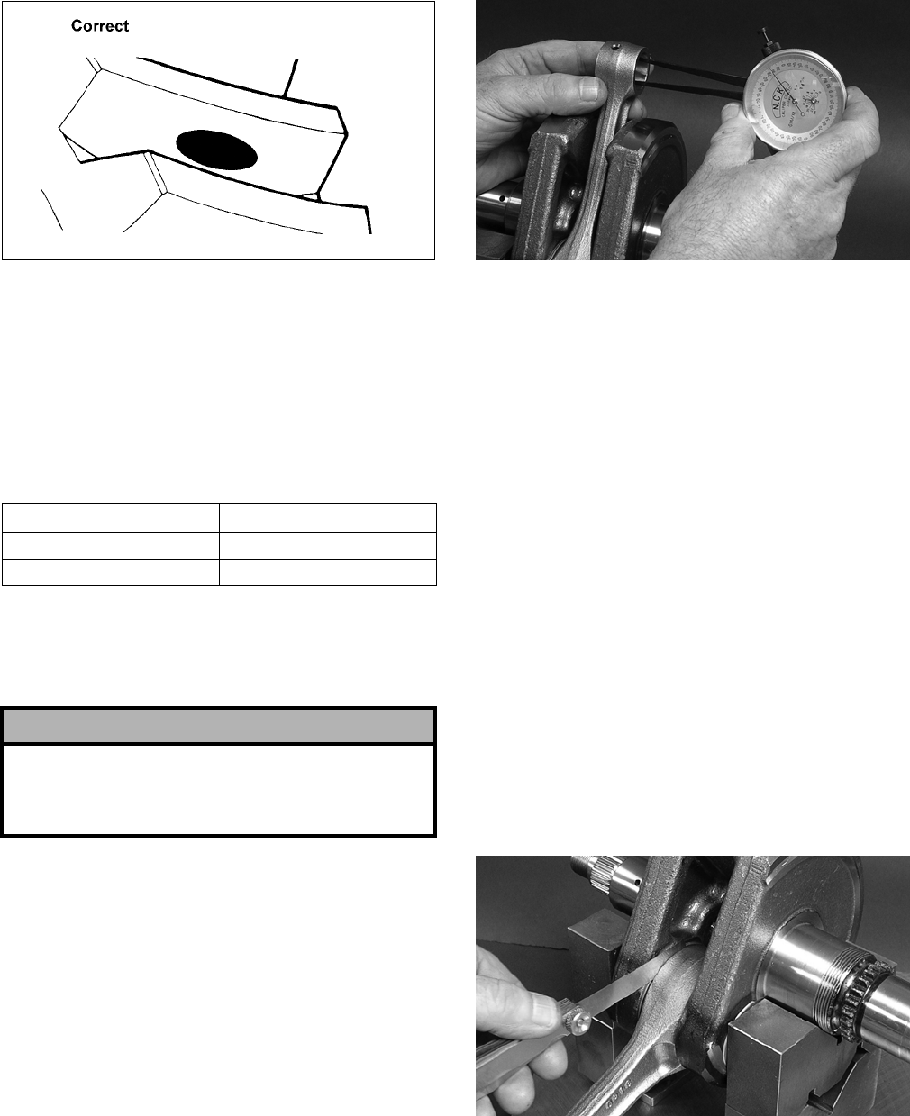
3-290
ATV-0104
Correcting Tooth Contact
NOTE: If tooth contact pattern is comparable to
the correct pattern illustration, no correction is
necessary.
If tooth contact pattern is comparable to an incorrect
pattern, correct tooth contact according to the fol-
lowing chart.
NOTE: To correct tooth contact, steps 1 and 2
(with NOTE) of “Correcting Backlash” must be fol-
lowed and the above “Tooth Contact/Shim Correc-
tion” chart must be consulted.
CRANKSHAFT ASSEMBLY
Measuring Connecting Rod
(Small End Inside Diameter)
1. Insert a snap gauge into the upper connecting
rod small end bore; then remove the gauge and
measure it with micrometer.
FI267
2. Maximum diameter must not exceed specifica-
tions.
Measuring Connecting Rod
(Small End Deflection)
1. Place the crankshaft on a set of V-blocks and
mount a dial indicator and base on the surface
plate. Position the indicator contact point against
the center of the connecting rod small end jour—
nal.
2. Zero the indicator and push the small end of the
connecting rod away from the dial indicator.
3. Maximum deflection must not exceed specifica-
tions.
Measuring Connecting Rod
(Big End Side-to-Side)
1. Push the lower end of the connecting rod to one
side of the crankshaft journal.
2. Using a feeler gauge, measure the gap between
the connecting rod and crankshaft journal.
FI266
3. Maximum gap range must not exceed specifica-
tions.
Tooth Contact Shim Correction
Contacts at Top Increase Shim Thickness
Contacts at Root Decrease Shim Thickness
! CAUTION
After correcting tooth contact, backlash must again
be checked and corrected (if necessary). Continue
the correcting backlash/correcting tooth contact pro-
cedures until they are both within tolerance values.
FOR ARCTIC CAT ATV DISCOUNT PARTS CALL 606-678-9623 OR 606-561-4983
www.mymowerparts.com
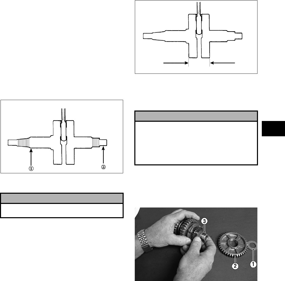
3-291
3
Measuring Connecting Rod
(Big End Width)
1. Using a calipers, measure the width of the con-
necting rod at the big-end bearing.
2. Acceptable width range must be within specifi-
cations.
Measuring Crankshaft (Runout)
1. Place the crankshaft on a set of V blocks.
2. Mount a dial indicator and base on the surface
plate. Position the indicator contact at point 1 of
the crankshaft.
ATV-1074
3. Zero the indicator and rotate the crankshaft slowly.
4. Maximum runout must not exceed specifications.
NOTE: Proceed to check runout on the other end
of the crankshaft by positioning the indicator con—
tact at point 2 and following steps 2-4.
Measuring Crankshaft
(Web-to-Web)
1. Using a calipers, measure the distance from the
outside edge of one web to the outside edge of
the other web.
ATV-1017
2. Acceptable width range must be within specifi-
cations.
COUNTERSHAFT
Disassembling
1. Remove the thrust washer (1); then remove the
low driven gear (2) and the bushing (3) noting
the orientation of the oil hole.
FI391A
2. Remove the low/reverse spacer (4), low/reverse
clutch dog (5), and reverse driven gear (6); then
noting the orientation of the oil hole, remove the
reverse driven gear bushing (7).
! CAUTION
Care should be taken to support the connecting rod
when rotating the crankshaft.
! CAUTION
When disassembling the countershaft, care must be
taken to note the direction each major component
(dog, gear) faces. If a major component is installed
facing the wrong direction, transmission damage
may occur and/or the transmission will malfunction.
In either case, complete disassembly and assembly
will be required.
FOR ARCTIC CAT ATV DISCOUNT PARTS CALL 606-678-9623 OR 606-561-4983
www.mymowerparts.com
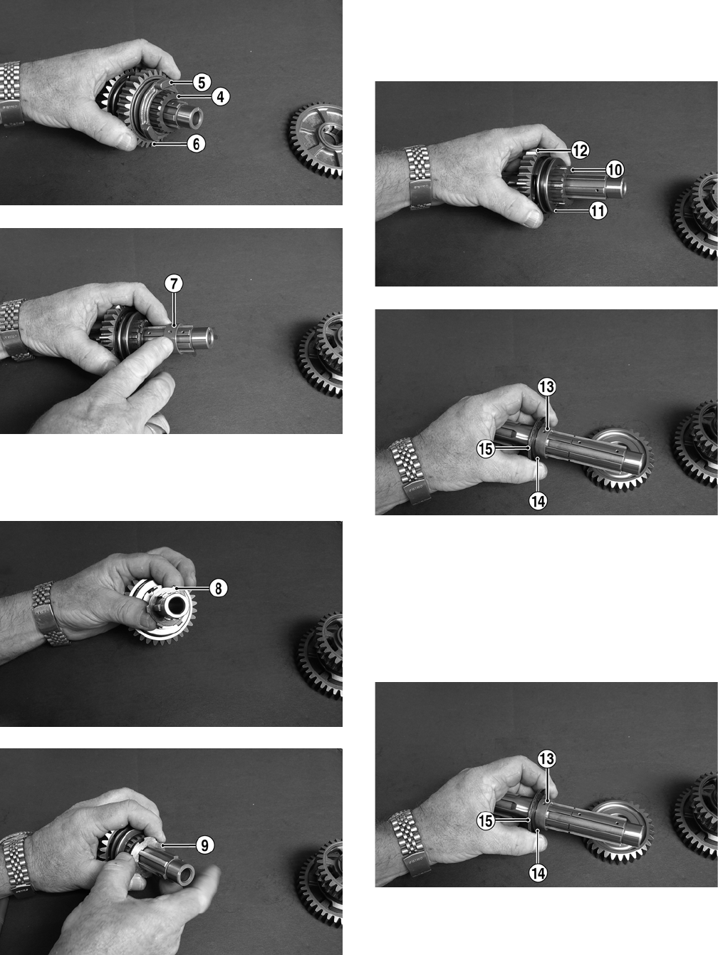
3-292
FI392A
FI393A
3. Remove the locking tab washer (8); then rotate
the thrust washer (9) and remove from the coun-
tershaft.
FI395A
FI396A
4. Remove the high driven gear spacer (10), high
driven clutch dog (11), and the high driven gear
(12). Account for the bushing (13), wave washer
(14), and thrust washer (15).
FI397A
FI399A
Assembling
1. Install the thrust washer (15), wave washer (14),
and bushing (13) on the countershaft; then
install the high driven gear (12) making sure the
wave washer (14) is aligned under the thrust
washer (15).
FI399A
FOR ARCTIC CAT ATV DISCOUNT PARTS CALL 606-678-9623 OR 606-561-4983
www.mymowerparts.com
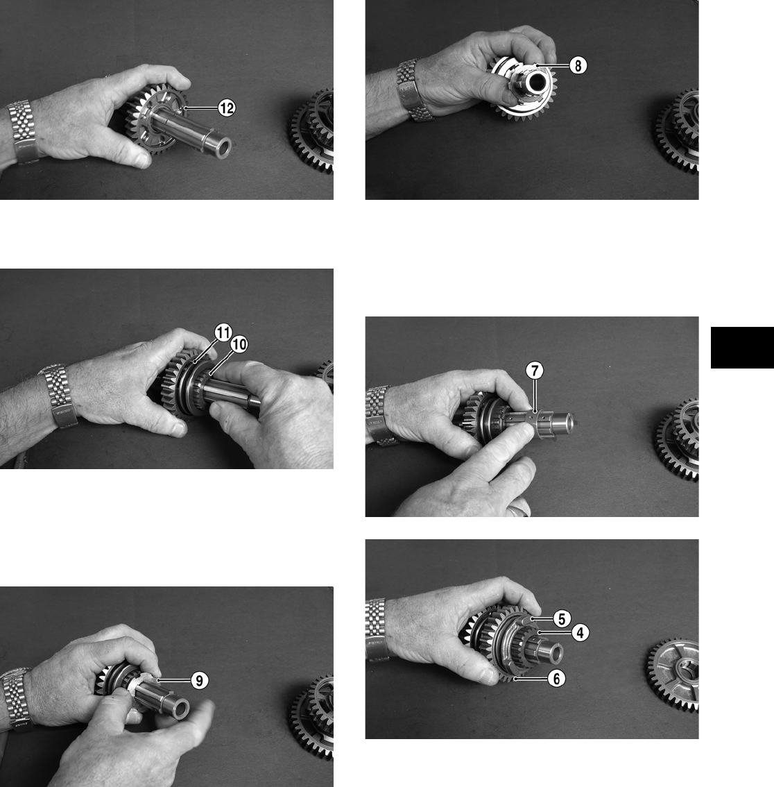
3-293
3
FI398A
2. Install the high driven gear spacer (10) and high
driven clutch dog (11).
FI402A
3. Position the thrust washer (9) onto the counter-
shaft; then while pressing toward the driven
gear, rotate the thrust washer to engage the
splines and install the locking tab washer (8)
making sure the tabs engage the splines.
FI396A
FI395A
4. Install the reverse driven gear bushing (7) mak-
ing sure to align the oil hole in the bushing with
the oil hole in the countershaft; then install the
reverse driven gear (6), low/reverse clutch dog
(5), and low/reverse spacer (4).
FI393A
FI392A
5. Install the low driven bushing (3) making sure
the oil hole in the bushing aligns with the hole in
the countershaft; then install the low driven gear
(2) and the thrust washer (1).
FOR ARCTIC CAT ATV DISCOUNT PARTS CALL 606-678-9623 OR 606-561-4983
www.mymowerparts.com
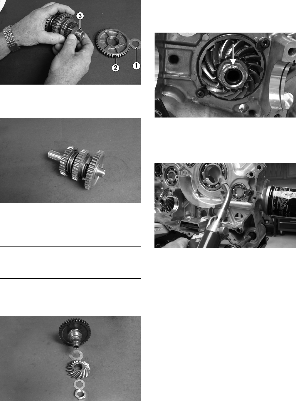
3-294
FI391A
NOTE: The countershaft is now completely
assembled and ready for installation.
FI406
NOTE: When installing the countershaft assem-
bly, account for the washer on each end of the
shaft.
Assembling Crankcase
Half
1. Install the output shaft assembly into the crank-
case making sure the driven bevel gear, shim,
washer, and nut are properly sequenced.
FI407
2. Apply red Loctite #271 to the threads of the out-
put shaft; then secure with the nut. Tighten nut
to specifications; then using a punch, peen the
nut as shown.
FI346A
3. Apply a liberal amount of engine oil to the
crankshaft bearing. Using a propane torch, heat
the bearing until the oil begins to smoke; then
slide the crankshaft assembly into place.
FI409
NOTE: If heating the bearing is not possible, the
crankshaft can be installed using a crankshaft
installing tool.
4. Install the drive pin (4) in the crankshaft; then
apply red Loctite #271 to the threads of the
crankshaft and install the crankshaft balancer
drive gear (2), washer (3), and nut (1). Tighten
to specifications; then using a punch, stake the
nut to the crankshaft.
FOR ARCTIC CAT ATV DISCOUNT PARTS CALL 606-678-9623 OR 606-561-4983
www.mymowerparts.com
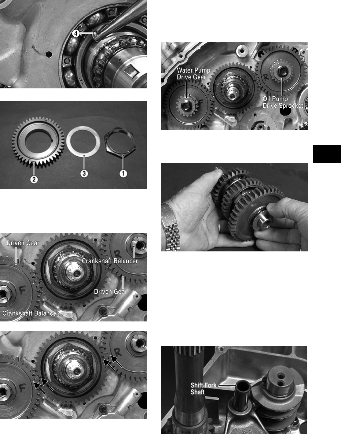
3-295
3
FI318A
FI305A
5. Install the front and rear crankshaft balancers;
then install the drive keys and driven gears mak-
ing sure the timing marks are properly aligned to
the drive gear timing marks.
FI303A
FI303B
6. Install the water pump drive gear on the front
crankshaft balancer and the oil pump drive
sprocket on the rear crankshaft balancer; then
thread in but do not tighten the cap screws at this
time.
FI441A
7. Install the assembled countershaft; then install
the driveshaft.
FI343
8. Install the shift cam assembly making sure the two
holes on the end of the shaft are positioned
vertically.
9. Insert the two shift forks into the sliding dogs
noting the direction of the tabs from disassem-
bling; then install the gear shift fork shaft.
NOTE: Make sure the shift fork tabs face upward
and that they are properly seated into the shift
cams.
FI282A
FOR ARCTIC CAT ATV DISCOUNT PARTS CALL 606-678-9623 OR 606-561-4983
www.mymowerparts.com
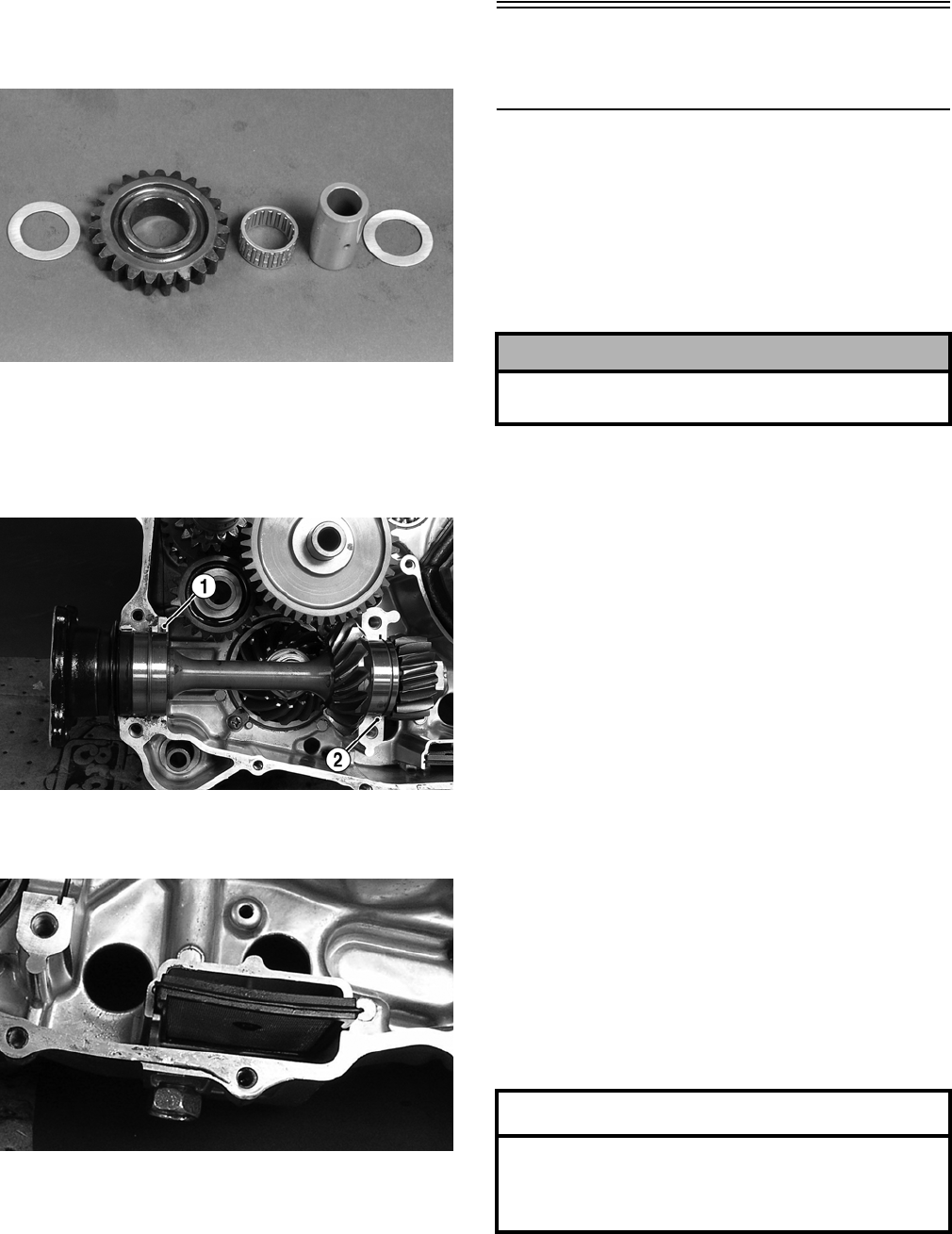
3-296
10. Install the reverse idler gear assembly noting the
positioning of the two washers, gear, bushing,
and shaft.
FI291
11. Install the rear secondary driven shaft assembly
into the left side of the crankcase making sure
the bearing locating pin (1) is facing upward and
the bearing C-ring (2) is fully seated in the
crankcase.
FI288A
12. Place the oil strainer into position in the left
crankcase half.
FI299
13. Install the two alignment pins in the left crank-
case half.
Joining Crankcase
Halves
1. Apply High-Temp Sealant to the left-side mat-
ing surface.
2. Lightly oil all bearings and grease all shafts in
the right-side crankcase.
3. Making sure to align the shafts and alignment
pins, join the two crankcase halves.
4. Using a plastic mallet, lightly tap the case halves
together until cap screws can be installed.
5. From the right side, install the 8 mm cap screws
(two inside the case); then tighten only until
snug.
NOTE: Rotate the shafts back and forth to
ensure no binding or sticking occurs.
6. From the right side, install the 6 mm cap screws
(two inside the case); then tighten only until
snug.
NOTE: Rotate the shafts back and forth to
ensure no binding or sticking occurs.
7. In a crisscross pattern, tighten the 8 mm cap
screws (from step 5) until the halves are cor-
rectly joined; then tighten to specifications.
NOTE: Rotate the shafts back and forth to
ensure no binding or sticking occurs.
8. In a crisscross pattern, tighten the 6 mm cap
screws (from step 6) to specifications.
NOTE: Rotate the shafts back and forth to
ensure no binding or sticking occurs.
! CAUTION
Do not heat the bearing in the right-side crankcase
half. Damage to the oil seal will occur.
AT THIS POINT
After completing center crankcase components,
proceed to Installing Right-Side Components, to
Installing Left-Side Components, and to In- stalling
Top-Side Components.
FOR ARCTIC CAT ATV DISCOUNT PARTS CALL 606-678-9623 OR 606-561-4983
www.mymowerparts.com
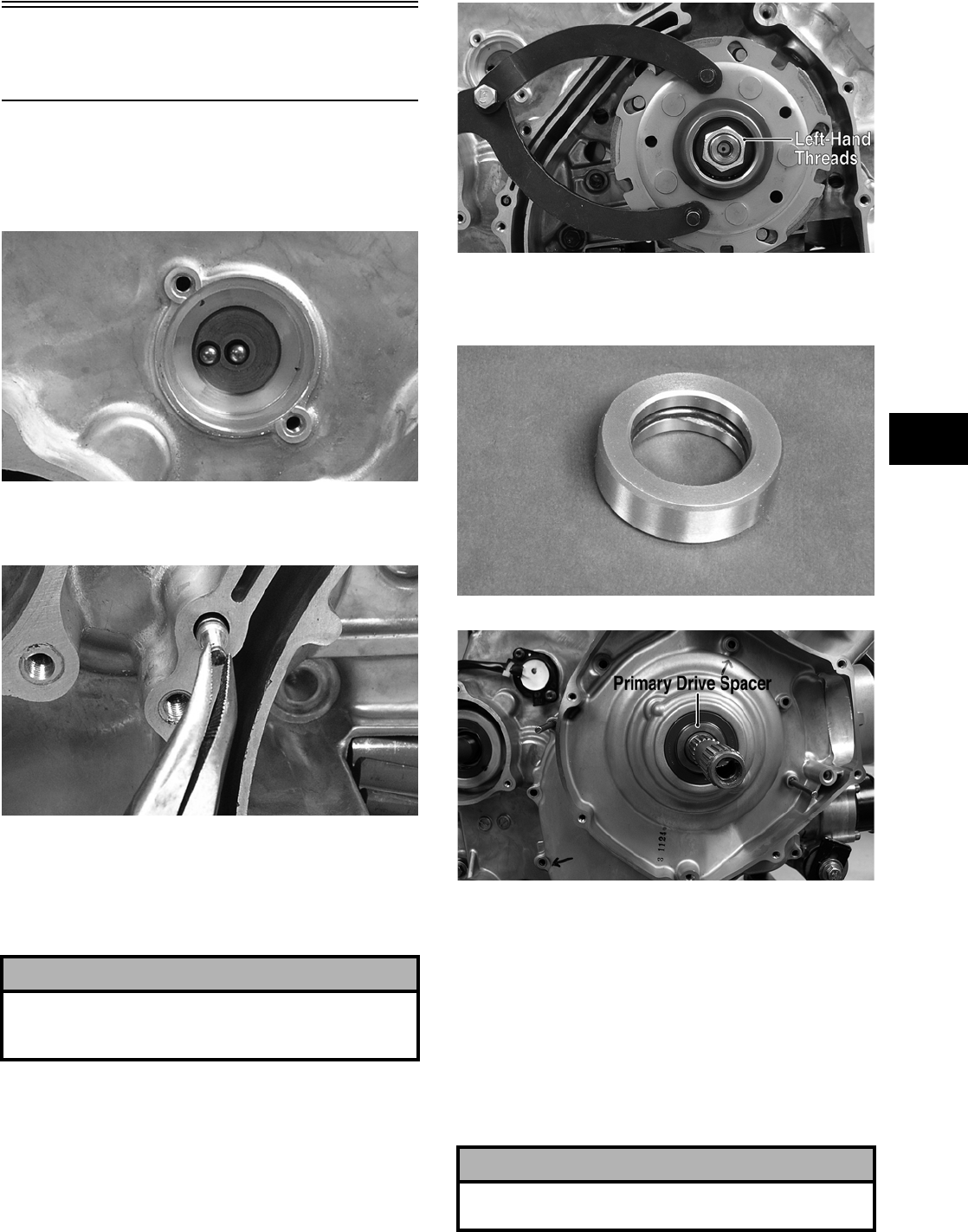
3-297
3
Installing Right-Side
Components
1. Install the shift indicator sending unit making
sure the two neutral contact pins and the two
springs are properly positioned. Tighten the
Allen-head screws securely.
FI281
2. Using a new O-ring, install the oil jet in the right
side of the crankcase.
FI337
3. Install the clutch shoe assembly and secure with
the washer (with the flat side facing the assem-
bly as noted in removing) and the nut (threads
coated with red Loctite #271). Tighten to speci-
fications.
FI279A
4. Lightly grease the clutch housing seal; then
insert the primary drive spacer.
FI344
FI420A
5. Install the clutch cover alignment pins into the
crankcase, apply oil to the cover gasket, and
install the gasket onto the crankcase.
6. Apply grease to the outer edges of the clutch
housing; then from inside the clutch cover,
install the clutch housing into the cover using a
rubber mallet.
7. Install the one-way clutch onto the clutch shoe
assembly.
! CAUTION
Care must be taken that the directional washer be
installed correctly and note that the nut has
left-hand threads.
! CAUTION
When installed correctly, the green dot (or the word
OUTSIDE) on the one-way clutch is visible.
FOR ARCTIC CAT ATV DISCOUNT PARTS CALL 606-678-9623 OR 606-561-4983
www.mymowerparts.com
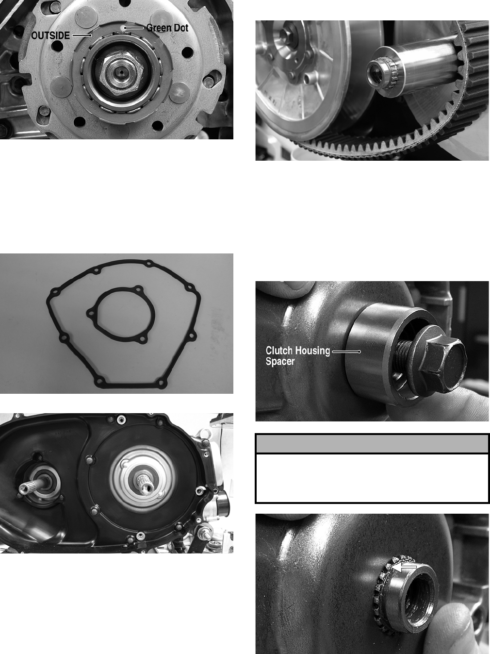
3-298
FI442A
8. Place the clutch cover/clutch housing assembly
into position on the crankcase; then secure with
the cap screws making sure the differ-
ent-lengthed cap screws are in their proper loca-
tion. Tighten to specifications.
9. Position the two gaskets in place on the crank-
case; then install the inner V-belt housing.
FI226
FI225
10. Place the driven pulley assembly into position
and secure with the nut. Tighten to specifica-
tions.
11. Slide the fixed drive face onto the shaft.
12. Spread the faces of the driven pulley by pushing
the inner face toward the engine while turning it
counterclockwise; then when the faces are sepa-
rated, press the V-belt down between the pulley
faces.
13. Place the V-belt into position over the front shaft.
FI221
NOTE: The arrows on the V-belt should point for-
ward.
14. Pinch the V-belt together near its center and
slide the movable drive face and clutch housing
spacer onto the shaft. Secure the drive face with
a cap screw (threads coated with red Loctite
#271). Tighten the cap screw to specifications.
FI429A
FI428A
! CAUTION
Make sure the splines extend beyond the movable
drive face plate or the clutch housing spacer may
become jammed when the cap screw is tightened.
This could result in a false torque reading.
FOR ARCTIC CAT ATV DISCOUNT PARTS CALL 606-678-9623 OR 606-561-4983
www.mymowerparts.com
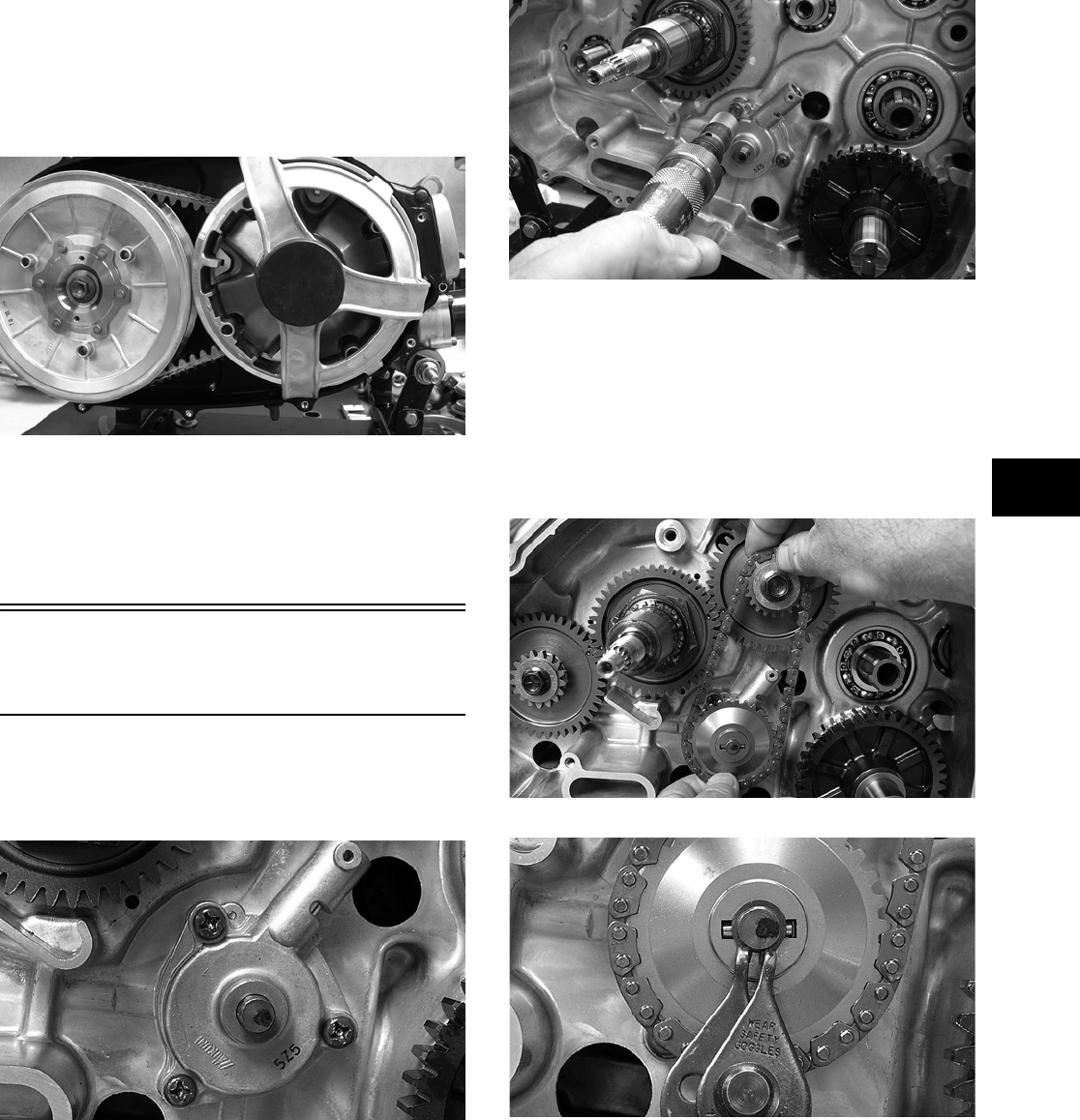
3-299
3
15. Rotate the V-belt and drive/driven assemblies
until the V—belt is flush with the top of the driven
pulley.
16. Install the V-belt housing assembly and tighten
the three cap screws securely.
FI220
17. Place the V-belt cover gasket into position; then
install the cover and secure with the cap screws
making sure the different-lengthed cap screws
are in their proper location. Tighten the cap
screws to specifications.
Installing Left-Side
Components
1. Install the oil pump securing it to the crankcase
with three Phillips-head cap screws (threads
coated with red Loctite #271). Tighten securely.
FI426
FI219
2. Install the drive pin in the oil pump shaft; then
with the drive chain around both the drive
sprocket and the driven sprocket, install the
driven sprocket onto the oil pump engaging the
drive pin. Secure with the circlip.
NOTE: The sharp side of the circlip should be
facing outward.
FI421
FI200
3. Apply red Loctite #271 to the two crankshaft
balancer cap screws and tighten to specifica-
tions.
FOR ARCTIC CAT ATV DISCOUNT PARTS CALL 606-678-9623 OR 606-561-4983
www.mymowerparts.com
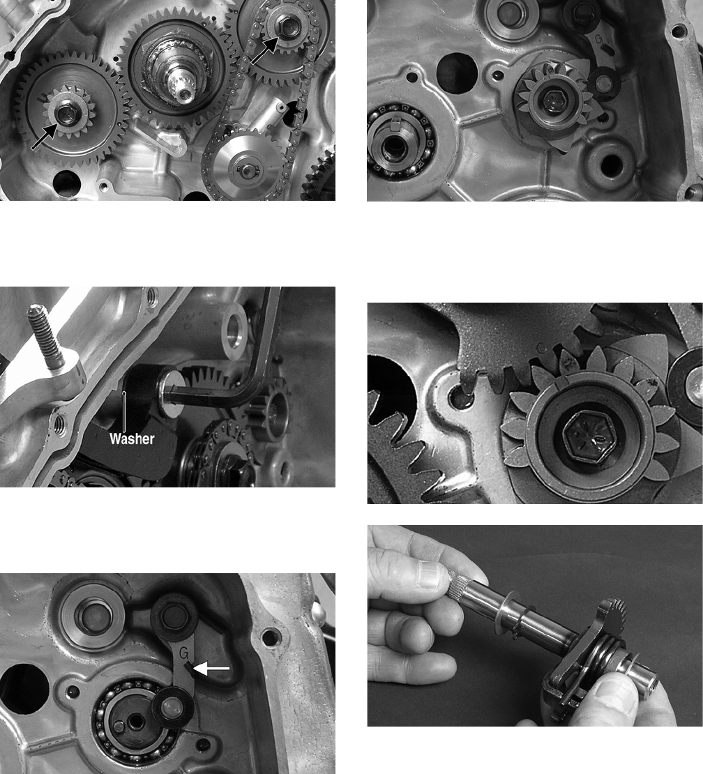
3-300
FI432A
4. Install the cam chain tensioner making sure the
washer is in place. Tighten the shoulder-bolt to
specifications.
FI197A
5. Install the shift cam stopper, spring, and washer.
Tighten the cap screw securely making sure the
stopper arm moves freely.
FI307B
6. Install the shift cam stopper plate. Tighten
securely.
FI311
7. Install the gear shift shaft with the index mark
aligned with the index mark on the shift cam
stopper plate. Make sure there is a washer on
both ends of the gear shift shaft.
FI427
FI302
8. Install the cam chain over the cam drive
sprocket; then secure the chain out of the way to
prevent it from falling into the crankcase.
FOR ARCTIC CAT ATV DISCOUNT PARTS CALL 606-678-9623 OR 606-561-4983
www.mymowerparts.com
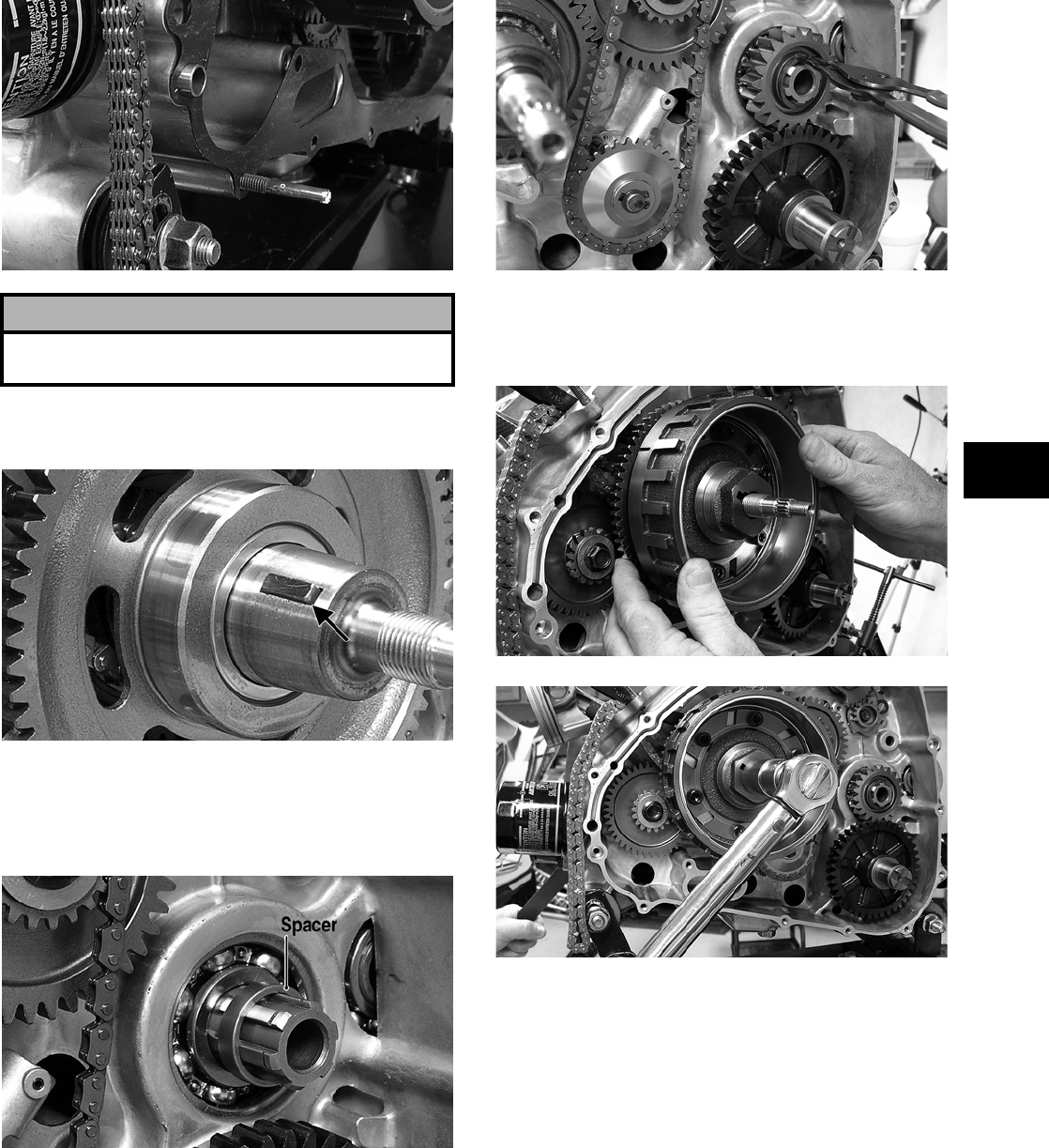
3-301
3
FI435
9. Install the starter driven gear; then install the
key in the crankshaft.
FI193A
10. Install the spacer on the driveshaft; then install
the output drive gear and secure with the circlip.
Make sure the flat side of the circlip is directed
away from the gear.
FI430A
FI422
11. Clean any oil or grease from the crankshaft and
rotor/flywheel and secure with the flange nut.
Tighten to specifications.
FI425
FI436
12. Install the starter idler gear and shaft; then with
a washer on each side, install the starter torque
limiter and bushings.
! CAUTION
Do not turn the engine with the cam chain loose or
severe engine damage will occur.
FOR ARCTIC CAT ATV DISCOUNT PARTS CALL 606-678-9623 OR 606-561-4983
www.mymowerparts.com
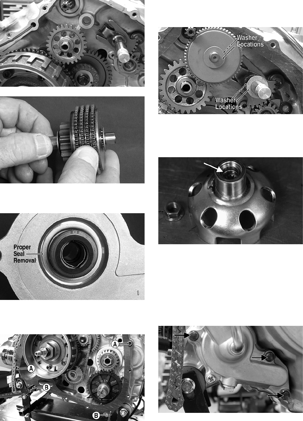
3-302
FI148
FI301
13. Install the two alignment pins (A) in the crank-
case; then place the gasket in position.
FI176A
NOTE: The use of alignment studs (B) will aid in
the installation of the magneto cover.
FI438A
14. Verify that the washers are properly located;
then install the magneto cover and secure with
the cap screws. Tighten only until snug.
FI185A
15. Place the starter cup into position on the crank-
shaft making sure a new, lubricated O-ring is
inside the cup. Tighten the flange nut to specifi-
cations.
CD925A
16. Tighten the cap screws (from step 14) to specifi-
cations.
17. Place the speed sensor housing and new O-ring
into position and secure with the cap screw.
Tighten securely.
18. Place the water pump into position and secure
with three cap screws. Tighten securely.
FI141A
FOR ARCTIC CAT ATV DISCOUNT PARTS CALL 606-678-9623 OR 606-561-4983
www.mymowerparts.com
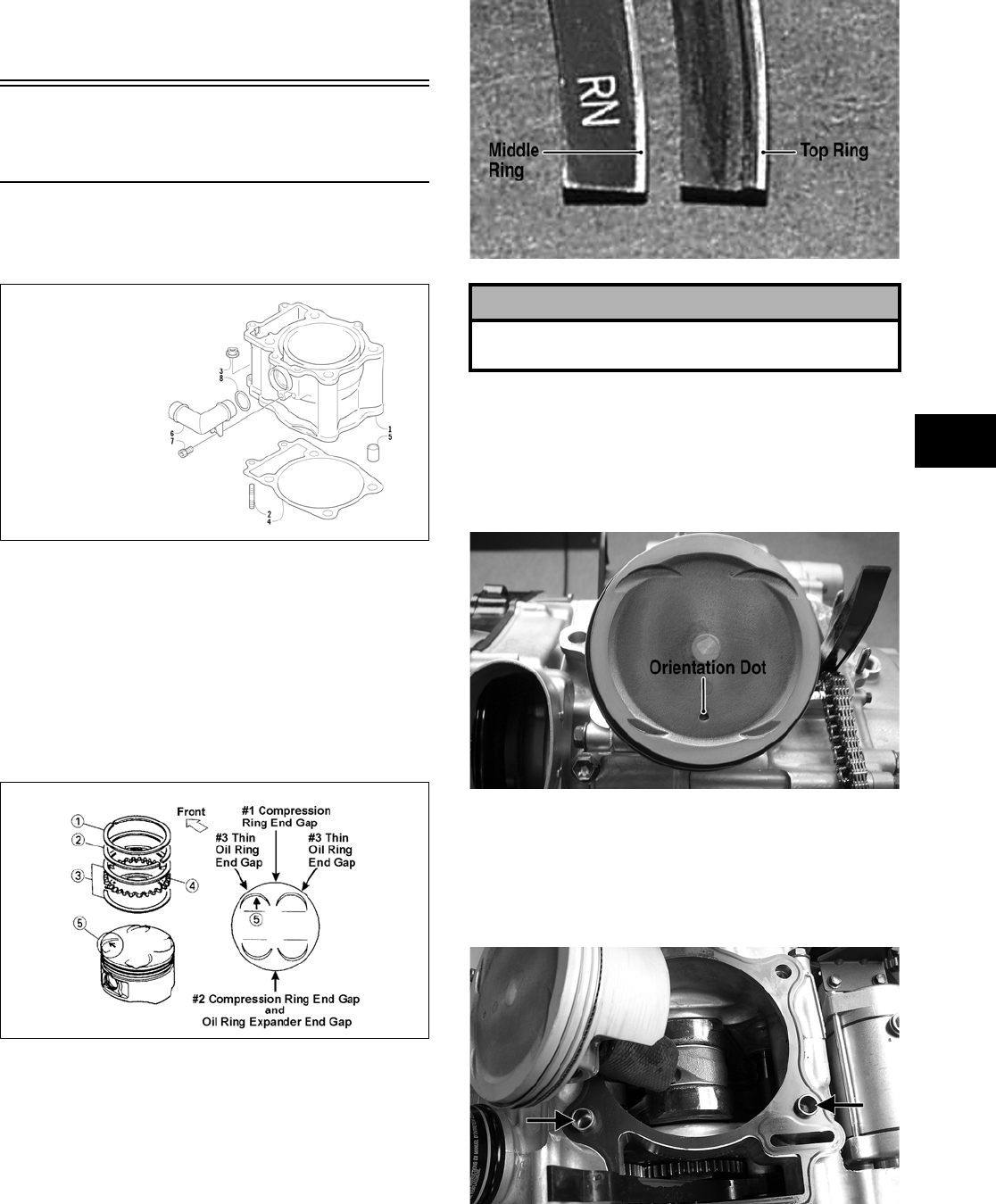
3-303
3
19. Place the gasket and recoil starter assembly into
position on the left-side cover; then tighten four
cap screws to specifications.
Installing Top-Side
Components
A. Piston
B. Cylinder
0732-301
NOTE: If the piston rings were removed, install
them in this sequence.
A. Install ring expander (4) in the bottom groove
of the piston; then install the thin oil rings (3)
over the expander making sure the expander
ends do not overlap. Stagger the end gaps of
the upper and lower thin oil rings according
to the illustration.
ATV-1085B
NOTE: Note the direction of the exhaust side of
the piston (5) for correct ring end gap orientation.
B. Install the middle ring (2) so the letters RN
are directed toward the top of the piston; then
install the top ring (1) with the lip directed
toward the top of the piston.
FI168A
1. Install the piston on the connecting rod making
sure there is a circlip on each side and the open
end of the circlip faces upwards.
NOTE: The piston should be installed so the ori-
entation dot is directed toward the exhaust.
FI138A
2. Place the two alignment pins into position. Place
the cylinder gasket into position; then place a
piston holder (or suitable substitute) beneath the
piston skirt and square the piston in respect to
the crankcase.
FI136A
KEY
1. Cylinder
2. Stud Bolt
3. Nut
4. Cylinder Gasket
5. Pin
6. Water Hose Union
7. Cap Screw
8. O-Ring
! CAUTION
Incorrect installation of the piston rings will result in
engine damage.
FOR ARCTIC CAT ATV DISCOUNT PARTS CALL 606-678-9623 OR 606-561-4983
www.mymowerparts.com
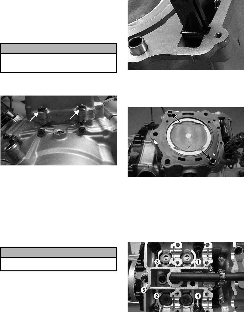
3-304
3. Lubricate the inside wall of the cylinder; then
using a ring compressor or the fingers, compress
the rings and slide the cylinder over the piston.
Route the cam chain up through the cylinder
cam chain housing; then remove the piston
holder and seat the cylinder firmly on the crank-
case.
4. Loosely install the two nuts which secure the
cylinder to the crankcase.
FI135A
NOTE: The two cylinder-to-crankcase nuts will
be tightened in step 10.
5. Install the coolant hose onto the crankcase union
and tighten the clamp.
C. Cylinder Head
NOTE: Steps 1-5 in the preceding sub-section
must precede this procedure.
6. Place the chain guide into the cylinder.
FI443
7. Place the head gasket into position on the cylin-
der. Place the alignment pins into position; then
place the head assembly into position on the cyl-
inder.
FI134A
8. Install the five 10 mm cylinder head cap screws
and tighten in the sequence shown to an initial
torque of 2.5 kg-m (18 ft-lb); then using the
same sequence, tighten to a final torque of 3.7
kg-m (27 ft-lb).
NOTE: Apply engine oil to the threads and both
sides of the washers before installing the cylinder
head cap screws.
FI133B
9. Install the four 6 mm flange-head cap screws
and tighten to specifications. Tighten the cylin-
der-to-crankcase nuts (from step 4) securely.
! CAUTION
The cylinder should slide on easily. Do not force the
cylinder or damage to the piston, rings, cylinder, or
crankshaft assembly may occur.
! CAUTION
Care should be taken that the bottom of the chain
guide is secured in the crankcase boss.
FOR ARCTIC CAT ATV DISCOUNT PARTS CALL 606-678-9623 OR 606-561-4983
www.mymowerparts.com
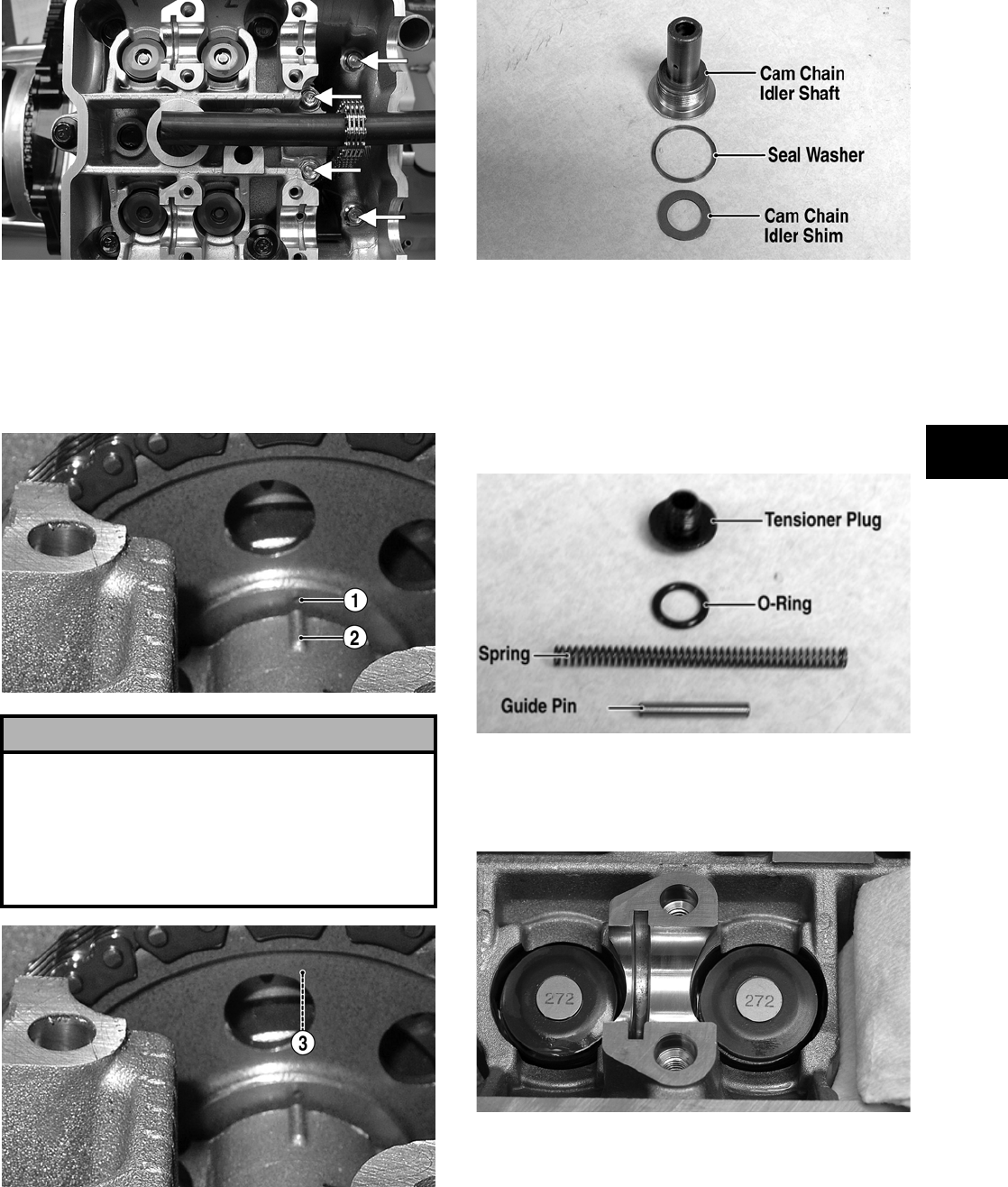
3-305
3
FI133C
10. Align the TDC line on the rotor/flywheel with
the index mark on the magneto cover; then
install the camshaft idler into the cam chain and
align the punch mark (1) with the index rib (2).
Adjust the idler in the chain as necessary to
align the marks.
FI447A
FI447B
11. When the idler gear is properly timed, place the
seal washer and cam chain idler shim on the cam
chain idler shaft; then install the shaft and
tighten to specifications.
FI131A
12. Install the cam chain tensioner with a new gas-
ket; then tighten the Allen-head cap screws to
specifications.
13. Install the spring and spring guide pin into the
cam chain tensioner; then with a new O-ring
installed on the tensioner plug, install the plug
and tighten to specifications.
FI159A
14. Install the proper tappet shims on the corre-
sponding valves as noted during removing; then
install the tappets as noted during removing.
FI053
! CAUTION
When checking the alignment, place tension on the
front of the chain by pulling up on the idler and rotat-
ing to the rear. The punch mark (1), index rib (2), and
gear tooth root (3) must align or engine damage will
occur. If all three cannot be aligned, remove the idler
and rotate the crankshaft one turn (360°) and repeat
step 10.
FOR ARCTIC CAT ATV DISCOUNT PARTS CALL 606-678-9623 OR 606-561-4983
www.mymowerparts.com
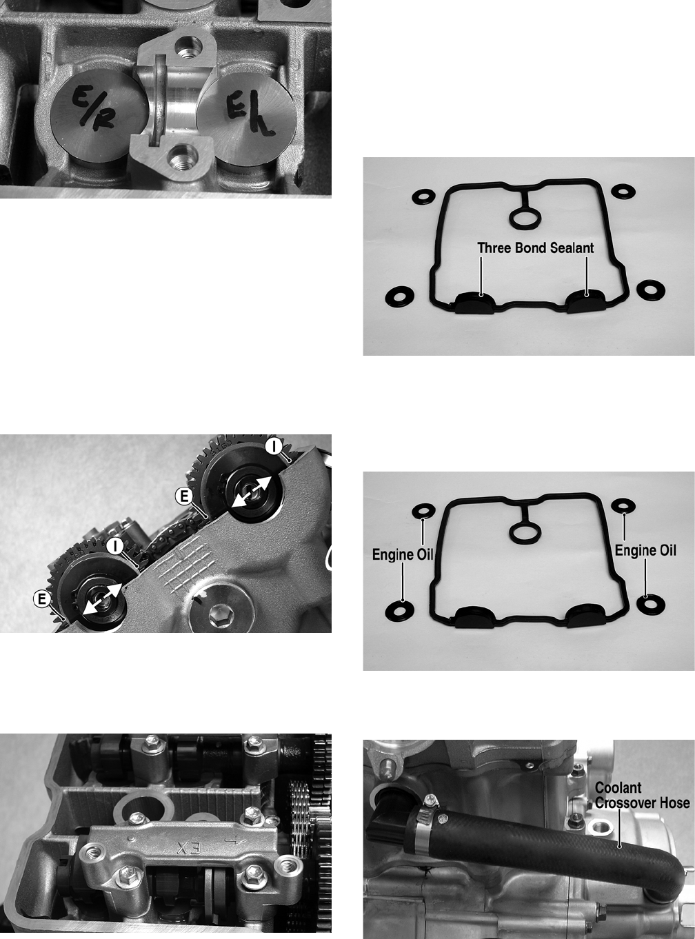
3-306
FI054
NOTE: The tappet shims must be installed with
the numbers facing the tappet.
15. Oil the tappets, camshaft journals, and cylinder
head journals with clean engine oil; then install
the four camshaft holder alignment pins.
16. With the TDC line aligned with the index mark
on the magneto cover, install the camshafts with
the engraved marks parallel with the top of the
cylinder head and the I and E directed toward
the intake or exhaust side of the head.
FI044A
17. Install the camshaft holders on the respective
camshaft with the arrows directed toward the
cam gears; then secure with the eight cap screws
and tighten to specifications.
FI047
18. Rotate the engine through three or four revolu-
tions; then rotate to top-dead-center (TDC) on
the compression stroke and check valve adjust-
ment (see Section 2).
19. With a new gasket installed on the cylinder head
cover, apply Three Bond Sealant (p/n 0636-070)
to the camshaft end caps; then place the head
cover into position on the cylinder head.
FI040A
20. Apply engine oil to the cylinder head cover seal
washers; then install the cylinder head cover cap
screws and seal washers. Tighten in a crisscross
pattern to 1.0 kg-m (7 ft-lb). Repeat in the same
pattern to a final torque of 1.4 kg-m (10 ft-lb).
FI040B
21. Install the coolant crossover hose on the water
pump and cylinder. Tighten the clamps securely.
FI161A
22. Install the timing inspection plug on the mag-
neto cover and tighten to specifications.
FOR ARCTIC CAT ATV DISCOUNT PARTS CALL 606-678-9623 OR 606-561-4983
www.mymowerparts.com
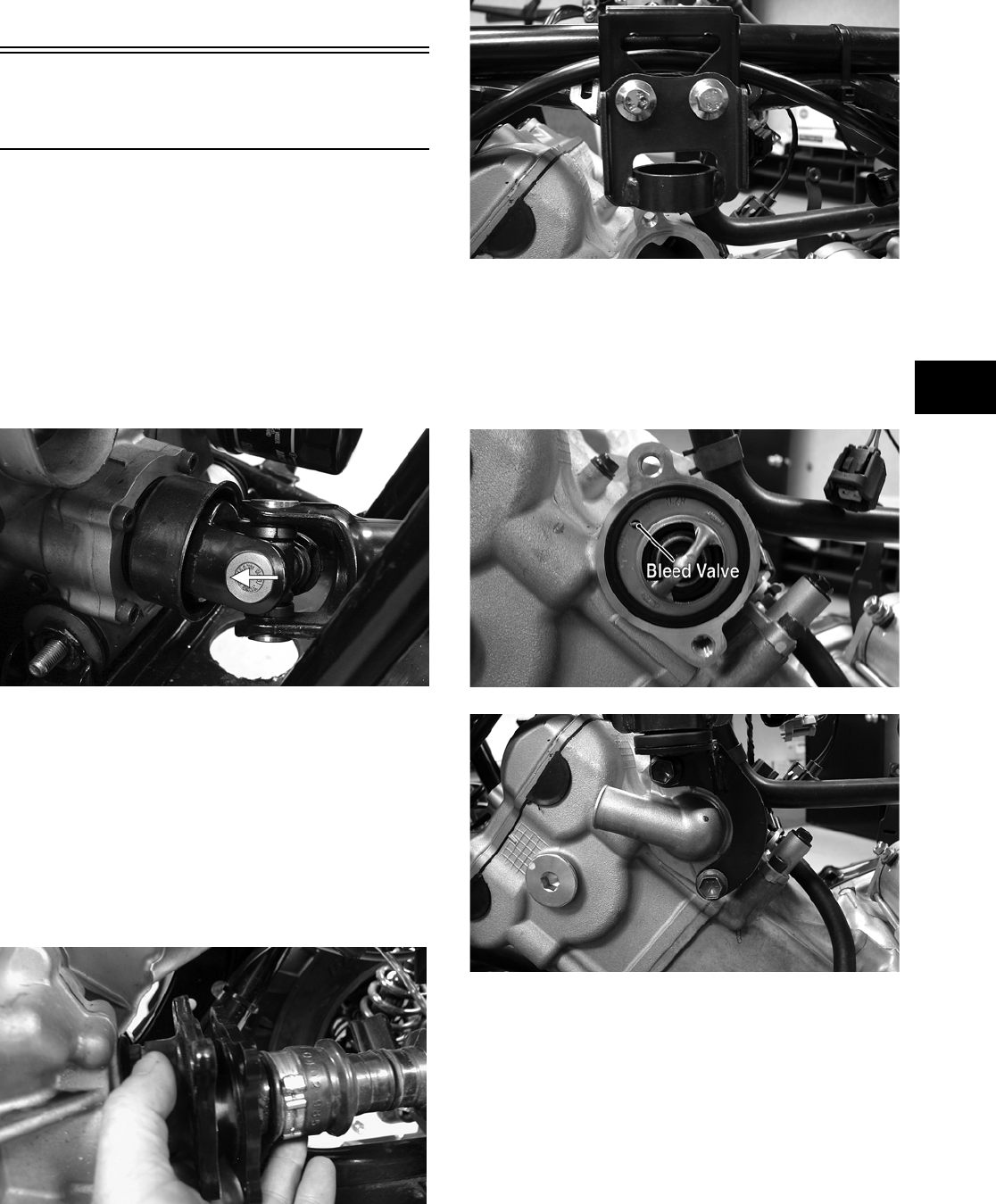
3-307
3
23. Place a new O-ring on the drive end of the
starter; then place a light coat of grease on the
O-ring and install the starter. Secure with the
two cap screws and tighten securely.
Installing
Engine/Transmission
NOTE: Arctic Cat recommends that new gaskets
and O-rings be installed whenever servicing the
ATV.
1. From the left side, place the engine/transmission
into the frame; then slide the engine rearward as
far as possible.
2. Raise the front of the engine and engage the front
drive output yoke onto the splined output shaft;
then lower the engine into the mounting brackets.
FI105B
3. Install the front through-bolt; then install the rear
through-bolt. Secure with new self-locking nuts
and tighten to specifications.
4. Align the rear drive flanges and secure with four
cap screws. Tighten to specifications.
NOTE: It is advisable to apply the brake lever
lock when tightening the cap screws securing the
rear driveshaft.
CD824
5. Secure the engine damper stopper to the frame
with the cap screws. Tighten only until snug.
FI111
6. Making sure the thermostat bleed valve is cor-
rectly oriented, install the thermostat housing
and engine damper mount; then secure with the
two cap screws and tighten to specifications.
Tighten the engine damper stopper cap screws
(from step 5) to specifications.
FI108A
FI112
7. Using a new O-ring, install the intake pipe on
the cylinder head making sure the UP mark is
directed toward the top of the engine; then
secure with the two cap screws and tighten
securely.
FOR ARCTIC CAT ATV DISCOUNT PARTS CALL 606-678-9623 OR 606-561-4983
www.mymowerparts.com
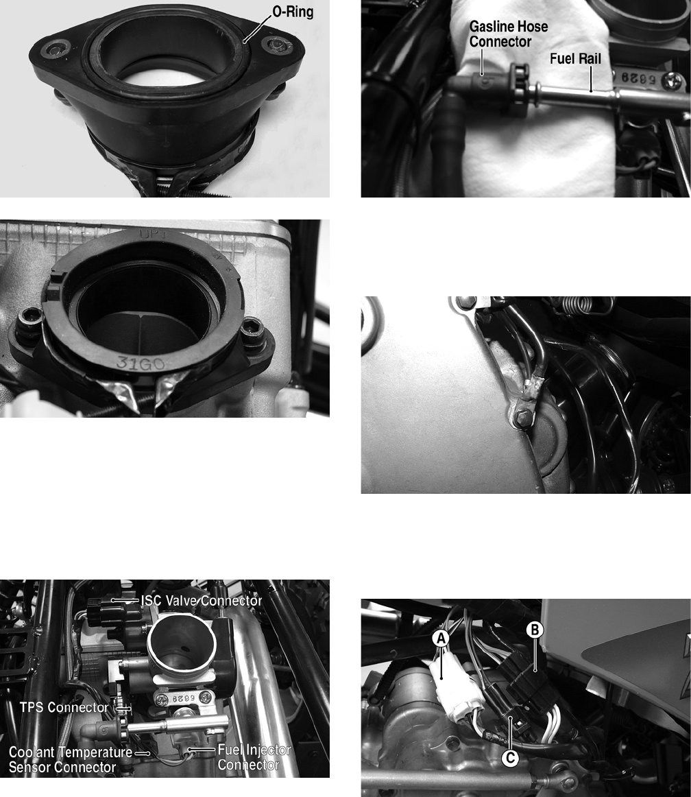
3-308
FI104A
FI103
8. Install the throttle body into the intake pipe and
tighten the clamp securely.
9. Connect the ISC valve connector, TPS connec-
tor, coolant temperature sensor connector, and
fuel injector connector to the appropriate sensor;
then connect the gasline hose connector to the
fuel rail.
FI089A
FI092A
10. Secure the engine ground wire and main harness
ground to the engine at the appropriate position
on the left-side cover and tighten the cap screw
to specifications.
FI084
11. Connect the gear position indicator connector
(A), stator connector (B), and the crankshaft
position sensor connector (C) to the main wiring
harness.
FI083A
12. Connect the starter positive cable to the starter
and tighten the nut securely.
FOR ARCTIC CAT ATV DISCOUNT PARTS CALL 606-678-9623 OR 606-561-4983
www.mymowerparts.com
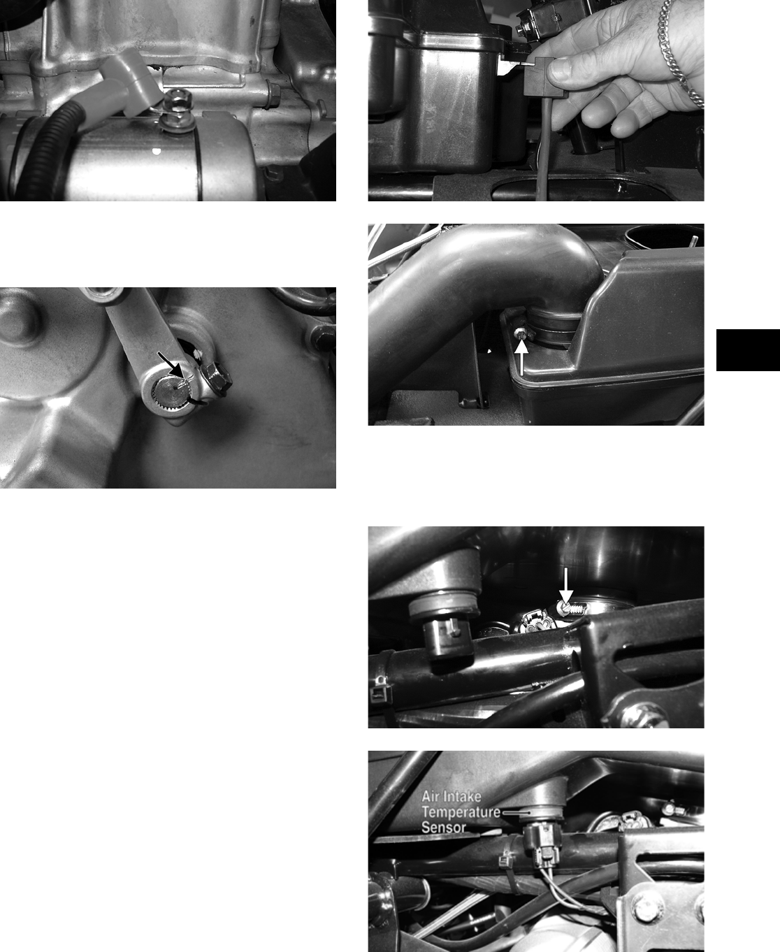
3-309
3
FI094
13. Place the shifter arm on the shift shaft aligning
the match marks; then install the cap screw and
tighten to specifications.
FI085A
14. Connect the speed sensor connector to the hous-
ing.
15. Install the exhaust pipe to the cylinder head
using a new grafoil seal; then secure with two
nuts and finger-tighten only. Connect the
exhaust pipe to the muffler and secure with the
two exhaust springs. Tighten the two exhaust
pipe nuts securely.
16. Secure all wiring to the frame and upper engine
bracket with cable ties.
17. Secure the two coolant hoses to the engine.
18. Place the air filter housing into position on the
frame and mount the intake air pressure sensor
on the mount; then install the air diverter assem-
bly and connect and secure the inlet air duct to
the air filter housing.
FI114
FI098A
19. Secure the air filter to the throttle body and
tighten the clamp securely; then connect the air
intake temperature sensor to the harness connec-
tor.
FI099A
FI082A
FOR ARCTIC CAT ATV DISCOUNT PARTS CALL 606-678-9623 OR 606-561-4983
www.mymowerparts.com
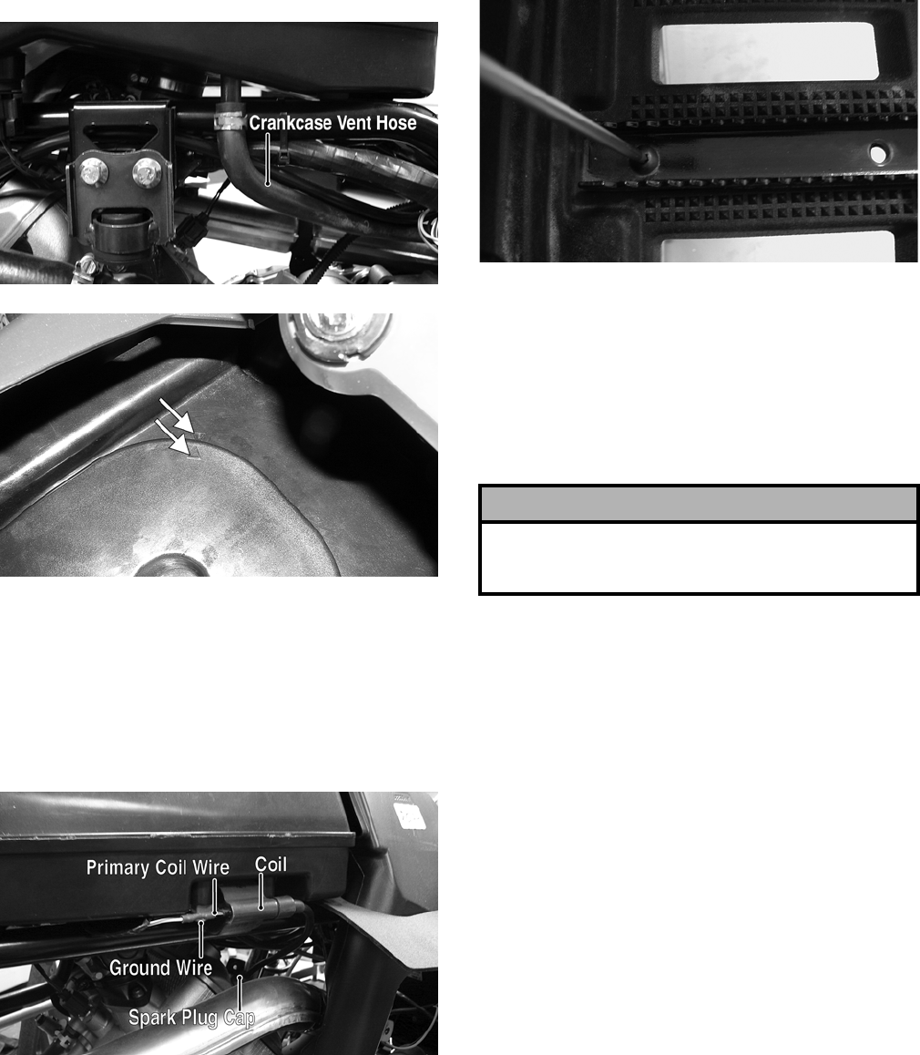
3-310
20. Secure the crankcase vent hose to the air filter
housing; then install the air filter and secure
with the air filter housing cover noting the align-
ment marks.
FI081A
FI035A
21. Connect the V-belt cooling inlet duct and outlet
boot and secure with the hose clamps. Tighten
securely.
22. Connect the spark plug cap/high tension lead to
the spark plug; then connect the primary coil
wire and ground wire to the coil. Tighten the
ground wire cap screw securely.
FI066A
23. Place the left-side footwell and foot peg in posi-
tion on the frame; then secure with existing
hardware. Tighten securely.
CD782
24. Install the front body panel with existing hard-
ware (see Section 8).
25. Place the side panels into position.
26. Place the battery into position in the battery
compartment; then install the battery cables and
vent hose. Secure with the battery cover.
27. Add proper amounts of engine/transmission oil
and coolant.
28. Install the seat.
! CAUTION
Battery acid is harmful if it contacts eyes, skin, or
clothing. Care must be taken whenever handling a
battery.
FOR ARCTIC CAT ATV DISCOUNT PARTS CALL 606-678-9623 OR 606-561-4983
www.mymowerparts.com

4-1
4
SECTION 4 —
FUEL/LUBRICATION/COOLING
TABLE OF
CONTENTS
Carburetor Specifications ……………….…………….….. 4-2
Carburetor Schematics (400/500/650 H1)……….….. 4-2
Throttle Body Assembly (700 EFI) …………………….. 4-2
Carburetor (400/500/650 H1) ……………….…………… 4-2
Electronic Fuel Injection (700 EFI) ………..…………… 4-7
Cleaning and Inspecting Carburetor
(400/500/650 H1) ……………………….………….…….. 4-8
Throttle Cable Free-Play ….…………….…………….….. 4-9
Engine RPM (Idle)…………..…………….…………….….. 4-9
Gas Tank ……………………….…………….………….…….. 4-9
Gas/Vent Hoses …………………..…………….…………… 4-9
Electric Fuel Pump (700 EFI) ……………………….….. 4-9
Vacuum Pulse Fuel Pump (400/500/650 H1)………. 4-9
Oil Flow Charts…………….…………….………….……… 4-10
Oil Filter/Oil Pump ………..…………….………….……… 4-11
Testing Oil Pump Pressure….…………….……………. 4-11
Oil Cooler (400)………………………….…………….…… 4-12
Oil Cooler (650 H1) …………………….…………….…… 4-12
Liquid Cooling System (500/650 H1/700 EFI)……. 4-13
Radiator…….…………….………….…………….…………. 4-13
Hoses/Thermostat (500/650 H1/700 EFI) …………. 4-14
Fan …………..…………….………….…………….…………. 4-14
Servicing Water Pump
(500 — Manual Transmission)………..…………….… 4-14
Servicing Water Pump (500/650 H1/700 EFI
— Automatic Transmission)……………..……………. 4-15
Testing Electric Fuel Pump (700 EFI)…….…………. 4-18
Testing Vacuum Pulse Fuel Pump
(400/500/650 H1) ……………………….………….…… 4-20
FOR ARCTIC CAT ATV DISCOUNT PARTS CALL 606-678-9623 OR 606-561-4983
www.mymowerparts.com
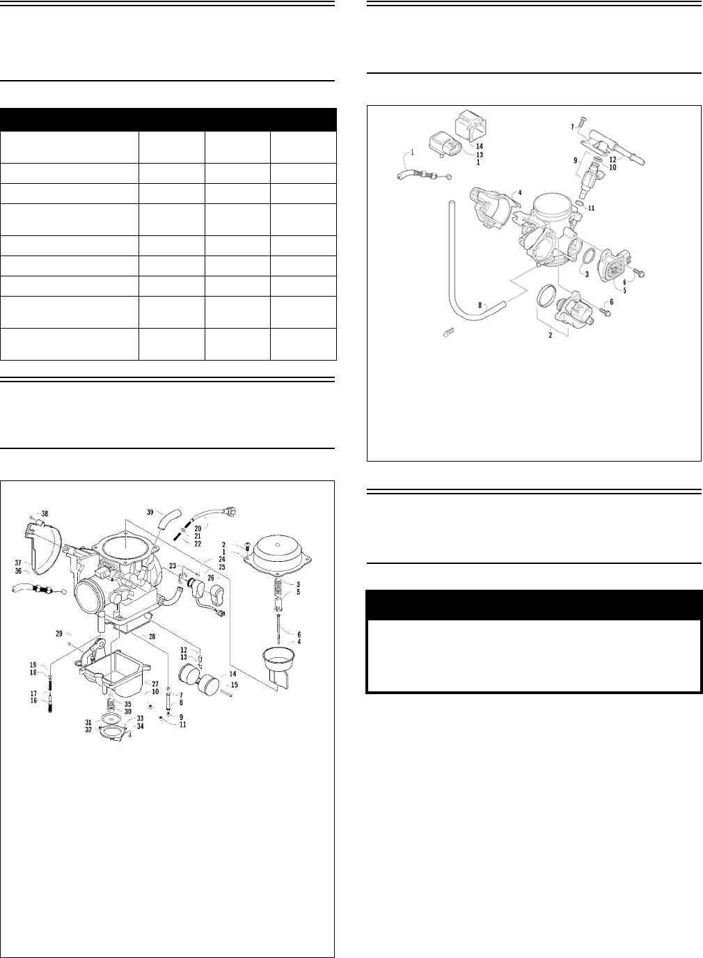
4-2
Carburetor
Specifications
Carburetor Schematics
(400/500/650 H1)
0739-656
Throttle Body Assembly
(700 EFI)
0741-277
Carburetor
(400/500/650 H1)
REMOVING
1. Remove the seat.
2. As necessary to access the carburetor, remove
the air-intake snorkel, the air cleaner housing
cover, or the air cleaner housing.
3. Disconnect the gasline hose from the carburetor
to the fuel pump.
4. Loosen the flange clamps; then remove the car-
buretor from the intake pipe.
5. Remove the screw securing the throttle actuator
cover to the carburetor; then remove the cover.
ITEM 400 500 650 H1
Carburetor Keihin
CVK34
Keihin
CVK36
Keihin
CVK36
Main Jet 135 138 132
Slow Jet 384040
Pilot Screw Setting
(turns)
1 3/4 1 3/4 1 1/4
Jet Needle NAZG NFKG NFKS
Idle RPM (engine warm) 1250-1350 1250-1350 1250-1350
Starter Jet 758585
Float Arm Height 17 mm
(0.7 in.)
17 mm
(0.7 in.)
17 mm
(0.7 in.)
Throttle Cable
Free-Play (at lever)
3-6 mm
(1/8-1/4 in.)
3-6 mm
(1/8-1/4 in.)
3-6 mm
(1/8-1/4 in.)
KEY
1. Cover
2. Screw
3. Spring
4. Vacuum Piston
5. Spring Seat
6. Jet Needle
7. Needle Jet
8. Jet Holder
9. Main Jet
10. Slow Jet
11. Starter Jet
12. Float Valve
13. Clip
14. Float
15. Float Pin
16. Pilot Screw
17. Spring
18. Washer
19. O-Ring
20. Idle Adjust
Screw
21. Washer
22. Spring
23. Plate
24. Screw
25. Electric Choke
26. Choke Cover
27. Float Chamber
Assy
28. O-Ring
29. Screw
30. Spring
31. Diaphragm
Assy
32. Pump Housing
33. U-Ring
34. Screw
35. Screw
36. Throttle Cable
37. Cover
38. Screw
39. Vent Hose
! WARNING
Whenever any maintenance or inspection is per-
formed on the fuel system during which there may
be fuel leakage, there should be no welding, smok-
ing, open flames, etc., in the area.
KEY
1. Throttle Cable
2. ISC Valve
3. O-Ring
4. Cover
5. Sensor Assy
6. Screw
7. Screw
8. Hose
9. Injector Assy
10. O-Ring
11. Seal
12. Delivery Pipe
13. Air Pressure Sensor
14. Holder
FOR ARCTIC CAT ATV DISCOUNT PARTS CALL 606-678-9623 OR 606-561-4983
www.mymowerparts.com
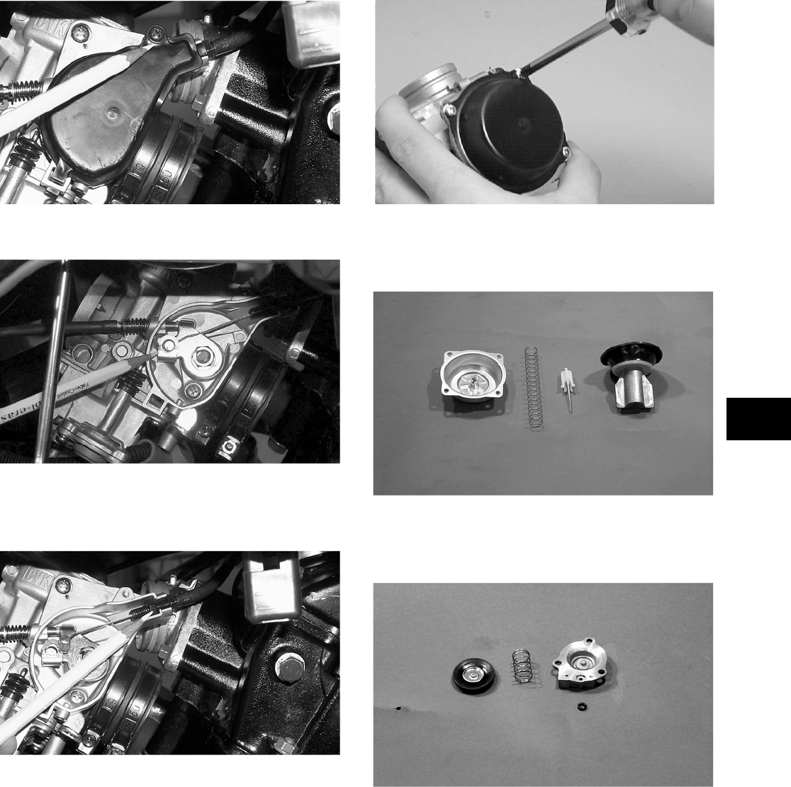
4-3
4
CC743
6. Remove the throttle cable from the actuator arm.
CC742
7. Loosen the outer jam nut securing the throttle
cable to the carburetor body; then route the
cable out of the way.
CC741
8. Disconnect the electric choke lead from the wir-
ing harness.
9. Disconnect the vent hose; then remove the car-
buretor.
DISASSEMBLING
1. Remove the four Phillips-head screws securing
the top cover; then remove the cover.
CH015D
2. Remove the vacuum piston assembly from the
carburetor body. Account for a spring, spring
seat, and the jet needle.
CC746
3. Remove the three screws securing the pump
housing. Account for the diaphragm assembly,
spring, and U-ring (in the housing).
CC748
4. Remove the Phillips-head screws securing the
float chamber; then remove the chamber.
Account for the O-ring.
FOR ARCTIC CAT ATV DISCOUNT PARTS CALL 606-678-9623 OR 606-561-4983
www.mymowerparts.com
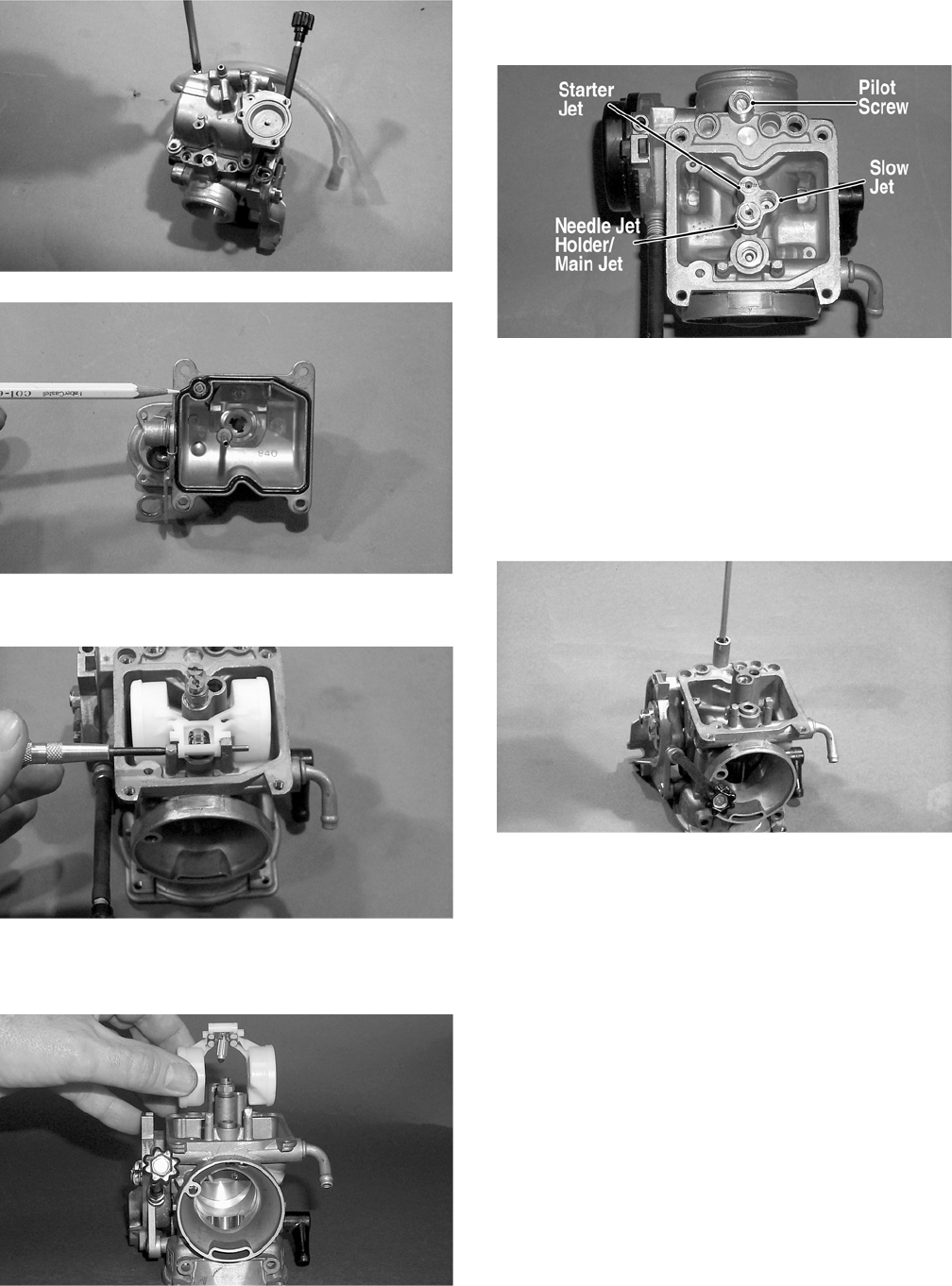
4-4
CC749
CC750
5. Remove the float pin.
CC752
6. Lift the float assembly from the carburetor.
Account for the float valve.
CC753
NOTE: Note the locations of the jets, pilot screw,
and holder for disassembling procedures.
CC761A
7. Secure the needle jet holder with a wrench; then
remove the main jet.
8. Remove the needle jet holder; then remove the
needle jet, slow jet, and the starter jet.
9. Remove the pilot screw. Account for a spring,
washer, and an O-ring.
CC758
10. Unscrew and remove the idle adjust screw.
Account for the spring and washer.
ASSEMBLING
1. Screw the idle adjust screw into the carburetor
making sure the washer and spring are properly
positioned.
2. Install the pilot screw, spring, washer, and
O-ring.
FOR ARCTIC CAT ATV DISCOUNT PARTS CALL 606-678-9623 OR 606-561-4983
www.mymowerparts.com
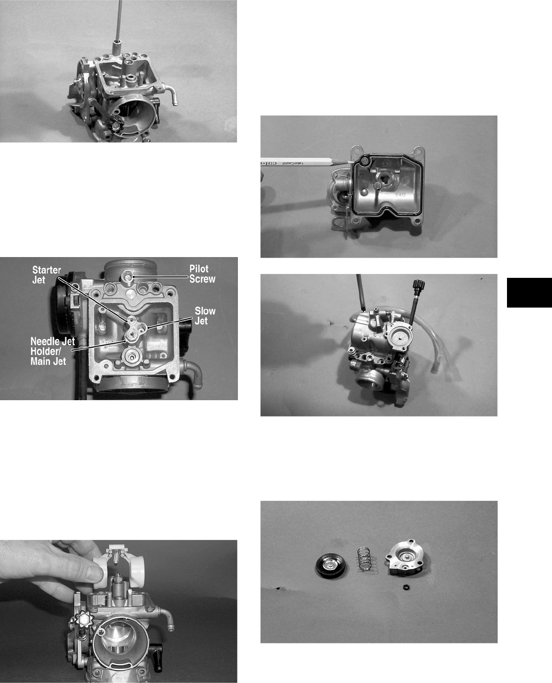
4-5
4
CC758
NOTE: Turn the pilot screw clockwise until it is
lightly seated; then turn it counterclockwise the
recommended number of turns as an initial set-
ting.
NOTE: Note the locations of the jets and holder
during assembling procedures.
CC761A
3. Install the slow jet. Tighten securely.
4. Install the main jet into the needle jet holder and
tighten securely; then install the needle jet and
needle jet holder assembly into the carburetor
and tighten securely.
5. Place the float assembly (with float valve) into
position and secure to the carburetor with the
float pin.
CC753
NOTE: Check float arm height by placing the car-
buretor on its side w/float contacting the needle;
then measure with a caliper the height when the
float arm is in contact with the needle valve. Float
arm height should be 17 mm (0.7 in.).
6. Place the float chamber into position making
sure the O-ring is properly positioned; then
secure with the Phillips-head screws.
CC750
CC749
7. Place the U-ring into the pump housing. Posi-
tion the spring and diaphragm assembly (lip
toward the carburetor) onto the carburetor; then
secure the assembly with the pump housing and
three screws. Tighten securely.
CC748
FOR ARCTIC CAT ATV DISCOUNT PARTS CALL 606-678-9623 OR 606-561-4983
www.mymowerparts.com
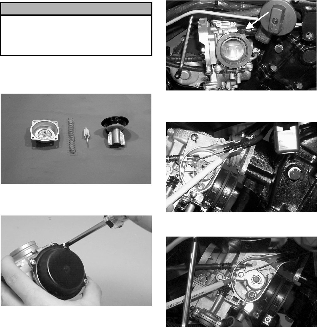
4-6
8. Place the jet needle, spring seat, and spring into
the vacuum piston; then place the assembly
down into the carburetor.
CC746
9. Place the top cover into position; then secure
with the Phillips-head screws. Tighten securely.
CH015D
INSTALLING
1. Connect the gas and vent hoses onto the carbu-
retor.
2. Connect the electric choke lead to the wiring
harness.
CC740A
3. Place the throttle cable into position and secure
by tightening the outer jam nut.
CC741
4. Connect the throttle cable to the actuator arm.
CC742
5. Place the throttle actuator cover into position on
the carburetor; then secure with the screw.
! CAUTION
It is important to press down on the pump housing
until it contacts the carburetor to make sure the dia-
phragm lip is properly seated in the groove in the
carburetor. If the diaphragm is not properly seated,
leakage will occur.
FOR ARCTIC CAT ATV DISCOUNT PARTS CALL 606-678-9623 OR 606-561-4983
www.mymowerparts.com
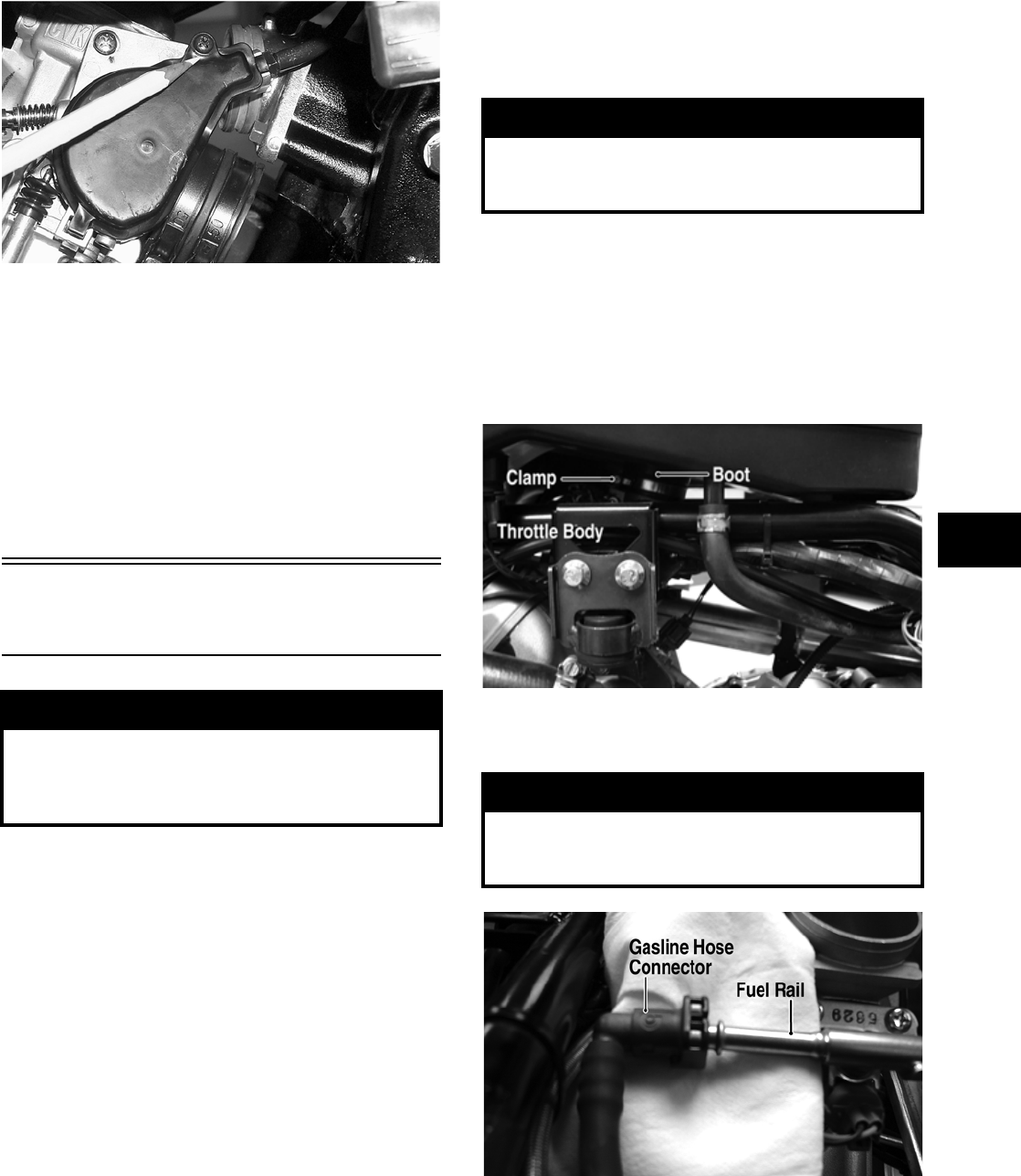
4-7
4
CC743
6. Position the carburetor in the air cleaner boot
and intake pipe assembly; then secure with the
clamps.
7. Connect the hose from the carburetor to the gas
tank.
8. As necessary, secure the air-intake snorkel, the
air cleaner housing cover, or the air cleaner
housing.
9. Install the seat.
Electronic Fuel Injection
(700 EFI)
TROUBLESHOOTING
1. Verify that the electric fuel pump is operating by
listening for a “whirring” sound for several sec-
onds after the ignition switch is turned to the ON
position. If no sound can be heard, see Testing
Electric Fuel Pump (700 EFI) in this section.
2. Check for a flashing EFI icon on the LCD dis-
play. If EFI is flashing, see ECU Error Codes
(700 EFI) in Section 5.
3. Make sure there is sufficient, clean gas in the
gas tank.
4. Verify that the battery is sufficiently charged to
crank the engine over at normal speed.
5. Check the air filter housing and air filter for con-
tamination. Clean or replace as necessary (see
Section 2).
REMOVING
1. Turn the ignition switch to the OFF position;
then remove the ignition switch key.
2. Disconnect the battery; then remove the seat.
3. Remove the storage compartment cover and air
filter housing cover; then remove the air filter.
4. Loosen the clamp securing the air filter housing
boot to the throttle body inlet; then remove the
boot from the throttle body.
FI081B
5. Slowly disconnect the gasline hose connector
from the fuel rail.
FI092A
6. Remove the screw securing the throttle actuator
cover to the throttle body; then remove the cover.
7. Remove the throttle cable from the actuator arm.
! WARNING
Whenever any maintenance or inspection is per-
formed on the fuel system during which there may
be fuel leakage, there should be no welding, smok-
ing, open flames, etc., in the area.
! WARNING
Do not turn the ignition switch to the ON position
with the hoses removed. Gasoline will be pumped by
the electric fuel pump causing a safety hazard.
! WARNING
Gasoline may be under pressure. Place an absor-
bant towel under the connector to absorb any gaso-
line spray when disconnecting.
FOR ARCTIC CAT ATV DISCOUNT PARTS CALL 606-678-9623 OR 606-561-4983
www.mymowerparts.com
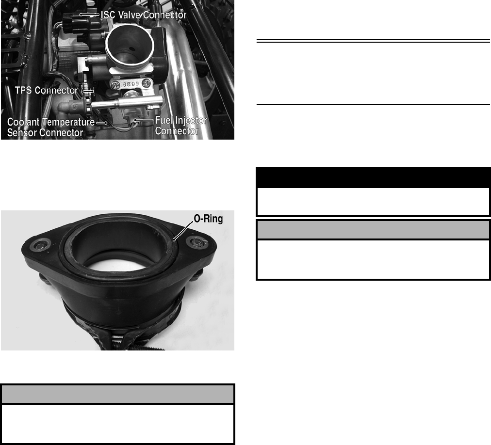
4-8
8. Loosen the outer jam nut securing the throttle
cable to the throttle body; then route the cable
out of the way.
9. Remove the four electrical connectors from the
throttle body components.
FI089A
10. Remove the cap screws securing the intake pipe
to the cylinder head and remove the throttle
body assembly; then remove the intake pipe
from the throttle body. Account for an O-ring.
FI104A
11. Use tape to cover and seal the intake opening.
INSTALLING
1. Install the throttle body into the intake pipe and
secure with the clamp. Tighten securely.
2. Place a new O-ring in the intake pipe; then posi-
tion the pipe onto the engine and secure with
two cap screws.
3. Connect the throttle cable to the throttle body
and adjust throttle free-play (see Section 2); then
connect the gasline hose.
4. Connect the four electrical connectors to the
throttle body components.
5. Install the air filter housing boot and secure with
the clamp; then install the air filter, air filter
cover, storage compartment, and storage com-
partment cover.
6. Install the seat making sure it locks securely in
place.
Cleaning and Inspecting
Carburetor
(400/500/650 H1)
NOTE: Whenever a part is worn excessively,
cracked, or damaged in any way, replacement is
necessary.
1. Place all metallic components in a wire basket
and submerge in carburetor cleaner.
2. Soak for 30 minutes; then rinse with fresh
parts-cleaning solvent.
3. Wash all non-metallic components with soap
and water. Rinse thoroughly.
4. Dry all components with compressed air only
making sure all holes, orifices, and channels are
unobstructed.
5. Inspect the carburetor body for cracks, nicks,
stripped threads, and any other imperfections in
the casting.
6. Inspect the vacuum piston/diaphragm for cracks,
imperfections in the casting, or cracks and tears
in the rubber.
7. Inspect float for damage.
8. Inspect gasket and O-rings for distortion, tears,
or noticeable damage.
9. Inspect tips of the jet needle, pilot screw, and the
needle jet for wear, damage, or distortion.
! CAUTION
Any objects or liquid entering the intake opening will
fall into the engine causing severe damage if the
engine is turned over or started.
! WARNING
When drying components with compressed air,
always wear safety glasses.
! CAUTION
DO NOT place any non-metallic components in
parts-cleaning solvent because damage or deterio-
ration will result.
FOR ARCTIC CAT ATV DISCOUNT PARTS CALL 606-678-9623 OR 606-561-4983
www.mymowerparts.com

4-9
4
10. Inspect the slow jet and main jet for obstructions
or damage.
NOTE: If the slow jet is obstructed, the mixture
will be extremely lean at idle and part-throttle oper-
ation.
11. Inspect the float valve for wear or damage.
12. Inspect the carburetor mounting flange for dam-
age and tightness.
Throttle Cable
Free-Play
To adjust throttle cable free-play, see Section 2.
Engine RPM (Idle)
(Carbureted Models)
To adjust the idle RPM, see Section 2.
Gas Tank
REMOVING
1. Remove the seat.
2. Remove the rear rack and fenders (see Section 8).
3. Disconnect the hose from the fuel pump to the
carburetor/throttle body.
4. Remove the cap screws securing the gas tank to
the frame.
5. Disconnect the fuel gauge connector; then
remove the gas tank.
CLEANING AND INSPECTING
NOTE: Whenever a part is worn excessively,
cracked, or damaged in any way, replacement is
necessary.
1. Clean all gas tank components with parts-clean-
ing solvent.
2. Inspect all hoses for cracks or leaks.
3. Inspect tank cap and tank for leaks, holes, and
damaged threads.
INSTALLING
1. Place the gas tank into position in the frame;
then install the cap screws. Tighten securely.
2. Connect the gas hose from the carburetor/throt-
tle body; then connect the fuel gauge connector.
3. Install the vent hose; then fill the gas tank with
gasoline.
4. Start the engine and inspect for leakage.
5. Install the rear fenders and rack (see Section 8);
then install the seat making sure it latches
securely.
Gas/Vent Hoses
Replace the gas hose every two years. Damage from
aging may not always be visible. Do not bend or
obstruct the routing of the carburetor/throttle body
vent hose. Make certain that the vent hose is
securely connected to the carburetor/throttle body
and the opposite end is always open.
Electric Fuel Pump
(700 EFI)
The electric fuel pump and fuel level sensor are not
serviceable components. If either fails, the fuel
pump assembly must be replaced.
NOTE: To test the fuel pump, see Testing Electric
Fuel Pump (700 EFI) in this section.
Vacuum Pulse Fuel
Pump
(400/500/650 H1)
The vacuum pulse fuel pump is not a serviceable
component. If the pump fails, it must be replaced.
! WARNING
Whenever any maintenance or inspection is made
on the fuel system during which there may be fuel
leakage, there should be no welding, smoking, open
flames, etc., in the area.
FOR ARCTIC CAT ATV DISCOUNT PARTS CALL 606-678-9623 OR 606-561-4983
www.mymowerparts.com
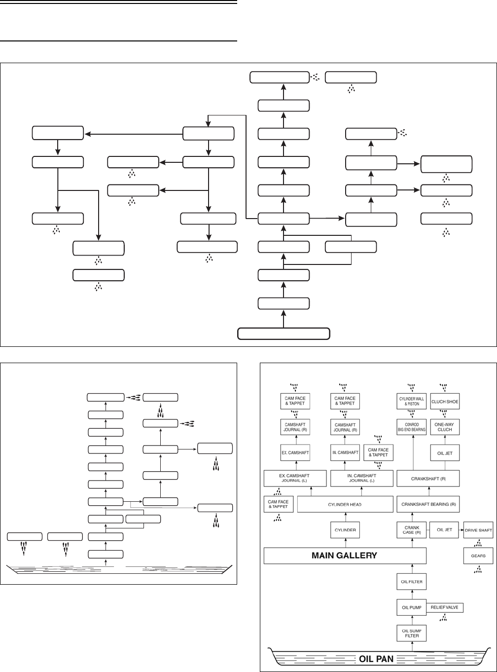
4-10
Oil Flow Charts
ATV-0111
ATV-1102
FI449
Driveshaft
Left End Bearing
Driveshaft
Secondary
Input Gears
Driveshaft Gears
and Reverse Gears
Bevel Gears
Secondary
Idle Gears
Countershaft Gears
Countershaft
Left End Bearing
Countershaft
Primary Driven
Gear Spacer
Second Clutch
Drive and Driven Plates
Intake and Exhaust
Cam Faces
Intake Rocker
Arm Shaft
Camshaft
Cylinder Head
Cylinder
Oil Gallery
Oil Filter
Oil Pump
Oil Strainer
Oil Sump
Cam Drive Chain
Starter Gear
Conrod Big-End
Bearing
Crankshaft
Crankshaft Right
End Bearing
Cylinder Wall
Piston Wall
Piston Ring
One-Way Clutch
First Clutch
Shoe
Relief Valve
400/500
(Manual Transmission)
Relief Valve
Crankshaft Right End
Bearing
Crankshaft
First Clutch Shoe
Conrod Big-End Bearing
Cylinder Wall
Piston Wall
Piston Ring
Starter Clutch
Cam Drive Chain
OIL SUMP
Bevel Gears Driveshaft Gears
& Reverse Gears
Oil Gallery
Oil Filter
Oil Pump
Oil Strainer
Cylinder
Cylinder Head
Cylinder Head Cover
Camshaft
Intake,
Rocker Arm Shaft
Intake and Exhaust
Cam Faces
400/500/650 H1
(Automatic Transmission) 700 EFI
FOR ARCTIC CAT ATV DISCOUNT PARTS CALL 606-678-9623 OR 606-561-4983
www.mymowerparts.com
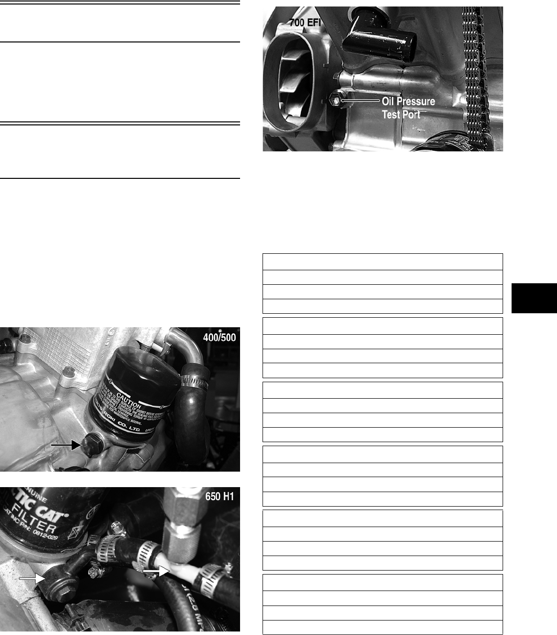
4-11
4
Oil Filter/Oil Pump
NOTE: Whenever internal engine components
wear excessively or break and whenever oil is con-
taminated, the oil pump should be replaced. The
oil pump is not a serviceable component.
Testing Oil Pump
Pressure
NOTE: The engine must be warmed up to the
specified temperature for this test.
1. Connect the Tachometer (p/n 0644-275) to the
engine.
2. Connect the Oil Pressure Test Kit (p/n
0644-495) to the oil filter drain plug (400/500),
in the oil pressure test port (700 EFI), or to the
upper oil cooler hose at the engine (650 H1).
CD457B
PR265B
FI439A
NOTE: Some oil seepage may occur when
installing the oil pressure gauge. Wipe up oil resi-
due with a cloth.
3. Start the engine and run at 3000 RPM. The oil
pressure gauge must read as specified.
NOTE: If the oil pressure is lower than specified,
check for an oil leak, damaged oil seal, defective
oil pump, or oil cooler.
400 (Manual Transmission)
OIL PRESSURE
0.6-1.0 kg/cm² (9-14 psi)
Oil Temperature — 60°C (140°F)
400 (Automatic Transmission)
OIL PRESSURE
1.1-1.5 kg/cm² (16-21 psi)
Oil Temperature — 60°C (140°F)
500 (Manual Transmission)
OIL PRESSURE
1.2-1.6 kg/cm² (17-23 psi)
Oil Temperature — 60°C (140°F)
500 (Automatic Transmission)
OIL PRESSURE
1.3-1.7 kg/cm² (18-24 psi)
Oil Temperature — 60°C (140°F)
650 H1
OIL PRESSURE (From Oil Cooler)
1.40-2.46 kg/cm² (15-25 psi)
Oil Temperature — 60°C (140°F)
700 EFI
OIL PRESSURE
1.4-1.8 kg/cm² (20-26 psi)
Oil Temperature — 110°C (230°F)
FOR ARCTIC CAT ATV DISCOUNT PARTS CALL 606-678-9623 OR 606-561-4983
www.mymowerparts.com
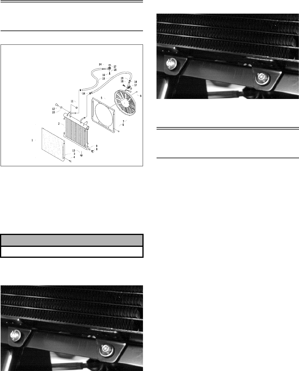
4-12
NOTE: If the oil pressure is higher than speci-
fied, check for too heavy engine oil weight (see
Section 2), clogged oil passage, clogged oil filter,
or improper installation of the oil filter.
Oil Cooler
(400)
0739-573
REMOVING
NOTE: It is not necessary to drain the engine oil
for this procedure.
1. Remove the input and output hoses from the fit-
tings on the cooler.
2. Remove the cap screws securing the oil cooler
to the frame. Account for grommets.
AL651D
3. Remove the oil cooler from the frame.
INSTALLING
1. Place the cooler into position in the frame.
2. Secure the cooler to the frame with the cap
screws and grommets.
AL651D
3. Install the hoses onto their respective fittings
and secure with the clamps.
Oil Cooler
(650 H1)
REMOVING
1. Disconnect the oil hoses from the oil cooler
located on the back of the radiator.
2. Remove the radiator (see Radiator) in this sec-
tion.
3. Remove the fan and fan shroud; then separate
the oil cooler from the radiator.
INSTALLING
1. Place the oil cooler into position on the radiator
and secure with the retainer brackets; then
install the fan shroud and fan.
2. Install the radiator (see Radiator) in this section.
3. Connect the oil hoses to the oil cooler and
tighten the clamps securely.
4. Warm up the engine and check for leaks; then
shut off the engine and check for the proper oil
level on the oil level stick. Add sufficient
amount of oil to raise the level above the lower
level mark.
! CAUTION
Elevate and secure the hoses to avoid oil spillage.
KEY
1. Oil Cooler Assy
2. Oil Cooler
3. Screen
4. Thumb Screw
5. Shroud
6. Machine Screw
7. Fan
8. Drain Plug
9. O-Ring
10. Grommet
11. Nut w/Washer
12. Shoulder Screw
13. Bushing
14. Clamp
15. Hose
16. Fitting
17. O-Ring
18. Cap Screw
19. Fitting
FOR ARCTIC CAT ATV DISCOUNT PARTS CALL 606-678-9623 OR 606-561-4983
www.mymowerparts.com
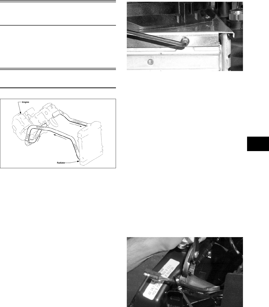
4-13
4
Liquid Cooling System
(500/650 H1/700 EFI)
The cooling system should be inspected daily for
leakage and damage. Also, the coolant level should
be checked periodically.
To check the cooling system, see Section 2.
Radiator
0732-411
REMOVING
1. Drain the coolant at the engine.
2. Remove the front rack (see Section 8).
3. Remove the front bumper and front fender panel
(see Section 8).
4. Remove the upper and lower coolant hoses.
5. Remove the cap screws and nuts securing the
radiator to the frame.
6. Disconnect the fan wiring from the main wiring
harness; then remove the radiator/fan assembly
and account for the grommets and collars.
7. Remove the fan/fan shroud assembly from the
radiator.
CC863
CLEANING AND INSPECTING
NOTE: Whenever a part is worn excessively,
cracked, or damaged in any way, replacement is
necessary.
1. Flush the radiator with water to remove any con-
taminants.
2. Inspect the radiator for leaks and damage.
3. Inspect all hoses for cracks and deterioration.
4. Inspect all fasteners and grommets for damage
or wear.
INSTALLING
1. Position the fan/fan shroud assembly on the
radiator; then secure with existing hardware.
2. Place the radiator with grommets and collars
into position on the frame; then install the cap
screws and nuts. Tighten securely.
3. Install the upper and lower coolant hoses; then
secure with hose clamps.
AF734D
4. Install the front bumper and front fender panel
(see Section 8).
5. Install the front rack (see Section 8).
FOR ARCTIC CAT ATV DISCOUNT PARTS CALL 606-678-9623 OR 606-561-4983
www.mymowerparts.com
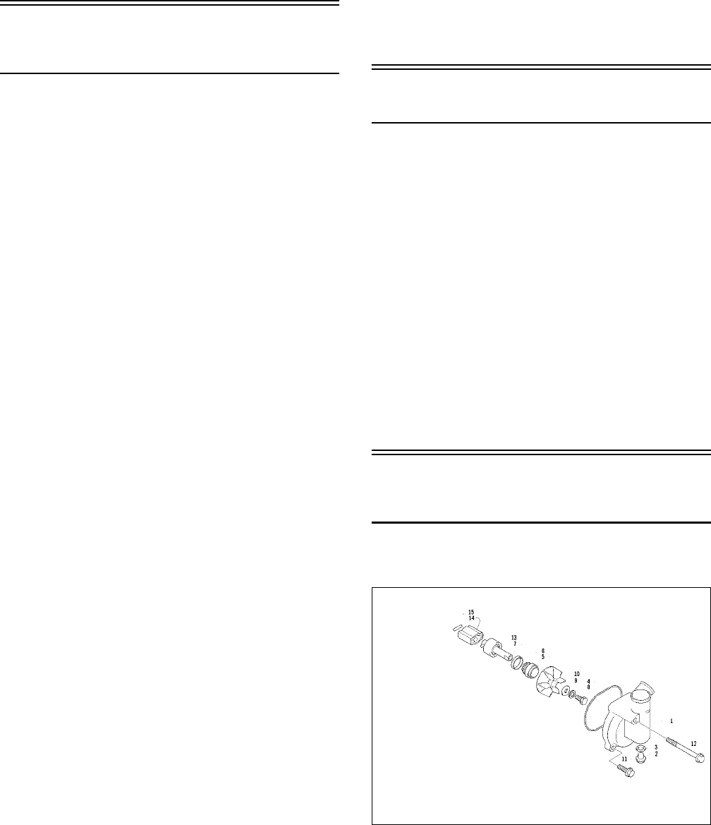
4-14
6. Fill the cooling system with the recommended
amount of antifreeze. Check for leakage.
7. Connect the fan wiring to the main wiring har-
ness.
Hoses/Thermostat
(500/650 H1/700 EFI)
REMOVING
1. Drain approximately one qt of coolant from the
cooling system.
2. Remove the two cap screws securing the ther-
mostat housing to the cylinder head. Account for
an O-ring and a thermostat.
INSPECTING
NOTE: Whenever a part is worn excessively,
cracked, or damaged in any way, replacement is
necessary.
1. Inspect the thermostat for corrosion, wear, or
spring damage.
2. Using the following procedure, inspect the ther-
mostat for proper operation.
A. Suspend the thermostat in a container filled
with water.
B. Heat the water and monitor the temperature
with a thermometer.
C. The thermostat should start to open at
73.5-76.5° C (164-170° F) on the 500/650 H1
and 80.5-83.5° C (177-182° F) on the 700
EFI.
D. If the thermostat does not open, it must be
replaced.
3. Inspect all coolant hoses, connections, and
clamps for deterioration, cracks, and wear.
NOTE: All coolant hoses and clamps should be
replaced every four years or 4000 miles.
INSTALLING
1. Place the thermostat and O-ring into the thermo-
stat housing; then secure the thermostat housing
to the cylinder head with the two cap screws.
2. Install the crossover coolant hose onto the water
pump and engine water inlet. Secure with the
two hose clamps.
3. Slide the upper hose onto the thermostat housing
and radiator. Secure with the two hose clamps.
4. Install the lower coolant hose onto the water
pump housing and radiator. Secure with the two
hose clamps.
5. Fill the cooling system with the recommended
amount of antifreeze. Check for leakage.
Fan
REMOVING
1. Remove the radiator (see Radiator in this sec-
tion).
2. Remove the fan assembly from the radiator.
INSTALLING
1. Position the fan assembly on the radiator; then
secure with existing hardware.
NOTE: The fan wiring must be in the upper-right
position.
2. Install the radiator (see Radiator in this section).
Servicing Water Pump
(500 — Manual Transmission)
REMOVING/DISASSEMBLING
0738-290
1. Drain the coolant.
KEY
1. Case
2. Cap Screw
3. Gasket
4. O-Ring
5. Impeller
6. Mechanical Seal
7. Seal
8. Cap Screw
9. Washer
10. Washer
11. Cap Screw
12. Cap Screw
13. Shaft w/Bearing
14. Joint
15. Pin
FOR ARCTIC CAT ATV DISCOUNT PARTS CALL 606-678-9623 OR 606-561-4983
www.mymowerparts.com
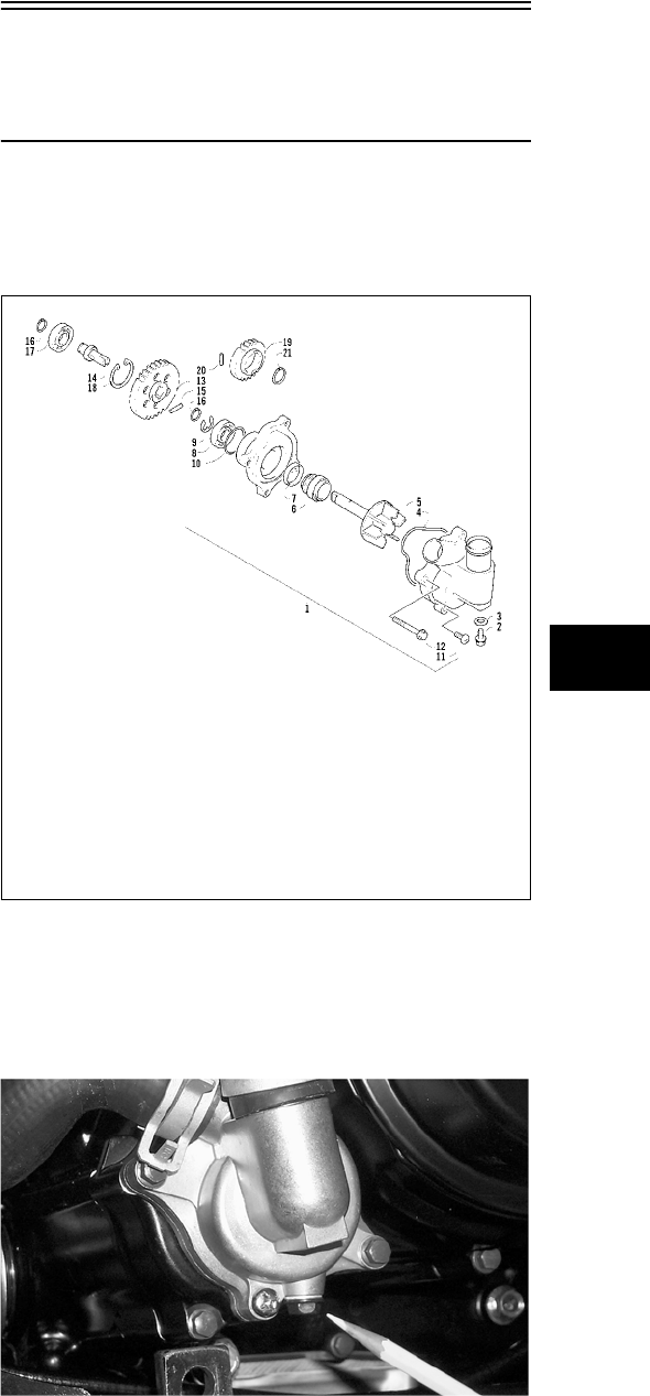
4-15
4
2. Remove the three cap screws securing the water
pump case. Note the position of the long cap
screw and account for the O-ring.
3. Remove the impeller cap screw, washer, and
gasket.
4. Remove the mechanical seal using this proce-
dure.
A. Tap the tip of a small sheet metal screw into
the inner-metal edge of the seal.
B. Grip the screw with a pair of vise-grip pliers
and pull the seal out. Account for the pump
drive seal.
CLEANING AND INSPECTING
NOTE: Whenever a part is worn excessively,
cracked, or damaged in any way, replacement is
necessary.
1. Clean all pump components in solvent.
2. Inspect the mechanical seal and pump drive seal
for damage.
NOTE: If the mechanical seal and/or pump drive
seal are damaged, they must be replaced as a set.
3. Inspect the impeller for corrosion or damage.
ASSEMBLING/INSTALLING
NOTE: Treat seals and O-rings with clean anti-
freeze for initial lubrication.
1. Press the mechanical seal with pump drive seal
into the impeller by hand.
2. Install the mechanical seal assembly onto the
water pump shaft and secure with the cap screw,
washer, and gasket. Tighten the cap screw
securely.
3. Place the water pump case into position and
secure with the three cap screws. Note the posi-
tion of the long cap screw from removal.
4. Fill the cooling system with the recommended
amount of antifreeze.
NOTE: While the cooling system is being filled,
air pockets may develop; therefore, run the engine
for five minutes after the initial fill, shut the engine
off, and then fill the cooling system.
5. Check the entire cooling system for leakage.
Servicing Water Pump
(500/650 H1/700 EFI —
Automatic Transmission)
NOTE: When servicing the water pump, it will be
necessary to install a new oil seal and a new
mechanical seal.
0737-766
REMOVING
1. Remove the radiator cap; then remove the water
pump drain and drain the coolant.
CC789
2. Drain the oil from the engine/transmission.
3. Remove the four torx-head cap screws securing
the front and rear fenders to the footrest; then
remove the four cap screws securing the footrest
to the frame. Remove the footrest.
KEY
1. Water Pump
Assy
2. Cap Screw
(Drain)
3. Gasket
4. O-Ring
5. Impeller/Shaft
6. Mechanical
Seal
7. Oil Seal
8. Bearing
9. E-Ring
10. O-Ring
11. Screw
12. Cap Screw
13. Driven Gear
14. Shaft
15. Pin
16. Circlip
17. Shaft
18. Circlip
19. Drive Gear
20. Pin
21. Circlip
FOR ARCTIC CAT ATV DISCOUNT PARTS CALL 606-678-9623 OR 606-561-4983
www.mymowerparts.com
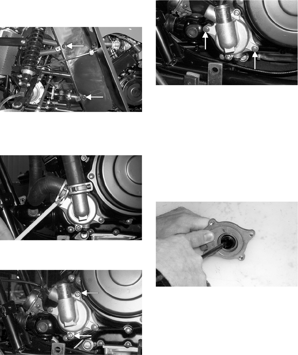
4-16
4. From inside the left-front wheel-well, remove
the two torx-head cap screws securing the
fender to the frame.
CC788A
5. Compress the tabs on the coolant hose clamps
and slide the clamps away from the hose ends
approximately 51 mm (2 in.); then remove both
hoses from the water pump.
CC784
6. Using an impact driver, loosen but do not
remove the two Phillips-head cover screws.
CC785A
7. Remove the two cap screws securing the water
pump to the engine; then remove the water
pump.
CC786A
DISASSEMBLING
1. Finish removing the two Phillips-head cap
screws securing the cover to the bearing hous-
ing; then remove the cover. Account for the
O-ring.
2. Remove the E-ring securing the impeller/shaft
to the bearing housing; then remove the impel-
ler/shaft.
3. Using Seal Removal Tool (p/n 0644-072),
remove the mechanical seal and the oil seal from
the bearing housing.
CC772
CLEANING AND INSPECTING
NOTE: Whenever a part is worn excessively,
cracked, or damaged in any way, replacement is
necessary.
1. Clean all oil-pump components in cleaning sol-
vent.
2. Inspect the impeller/shaft for corrosion or dam-
age.
FOR ARCTIC CAT ATV DISCOUNT PARTS CALL 606-678-9623 OR 606-561-4983
www.mymowerparts.com
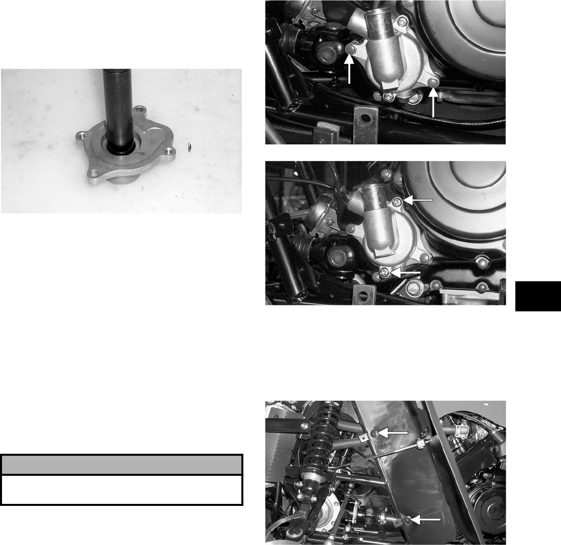
4-17
4
ASSEMBLING
1. Place the new oil seal into the bearing housing;
then using a seal driver, gently tap the seal down
until it is fully seated.
CC778
2. Place the new mechanical seal into the bearing
housing; then tap it down until it is fully seated.
NOTE: A large deep-well socket can be used to
drive the seal down evenly.
3. Install the impeller/shaft assembly into the bear-
ing housing; then secure with the E-ring.
NOTE: Make sure the E-ring is fully seated and
the impeller rotates freely.
4. While holding the bearing housing assembly in
position on the engine, slowly rotate the impel-
ler until the impeller/shaft engages properly
with its slot in the driven shaft.
NOTE: The bearing housing will be flush with the
engine when the two shafts are properly engaged.
5. With the bearing housing assembly in position
on the engine, place the cover (with O-ring
installed) into position on the housing; then
loosely secure with the two Phillips-head cap
screws.
INSTALLING
1. Secure the water pump to the engine with the
two cap screws tightened securely; then tighten
the two Phillips-head cap screws securely.
CC786A
CC785A
2. Connect the two coolant hoses to the water
pump and secure with the clamps.
3. From inside the left-front wheel-well, secure the
fender to the frame with the two torx-head cap
screws. Tighten securely.
CC788A
4. Place the footrest into position on the frame and
loosely secure with four cap screws; then secure
the front and rear fenders to the footrest with the
four torx-head cap screws. Tighten the four
torx-head cap screws securely; then tighten the
remaining cap screws to specifications.
5. Fill the engine/transmission with the proper
amount of recommended oil.
6. Fill the cooling system with the proper amount
of recommended coolant.
! CAUTION
Failure to properly engage the two shafts could
cause serious engine damage.
FOR ARCTIC CAT ATV DISCOUNT PARTS CALL 606-678-9623 OR 606-561-4983
www.mymowerparts.com
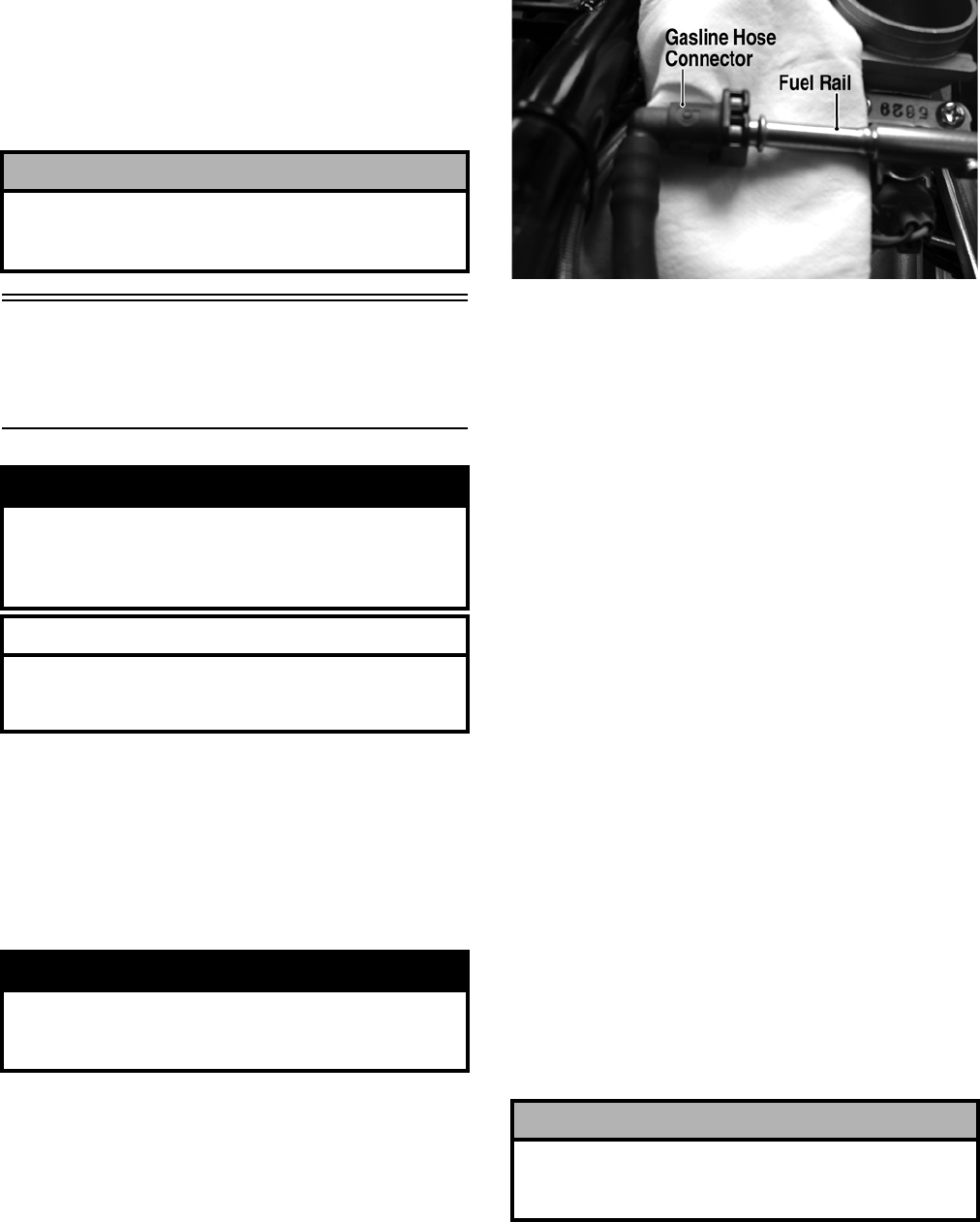
4-18
NOTE: While the cooling system is being filled,
air pockets may develop; therefore, run the engine
for five minutes after the initial fill, shut the engine
off, and then fill the cooling system.
7. Check the entire cooling system for leakage.
Testing Electric
Fuel Pump
(700 EFI)
1. Turn the ignition switch ON and listen for a
momentary “whirring” sound of the pump build-
ing pressure. If the sound is heard (10 seconds),
no electrical checks are necessary. Turn the igni-
tion switch OFF.
2. Disconnect the gasline hose from the throttle
body; then install a suitable pressure gauge.
FI092A
3. Turn the ignition switch to the ON position. The
fuel pressure should build until the pump shuts
off. Pressure should read 3.0 kg-cm2 (43 psi).
4. If the pump is not running, disconnect the fuel
pump/tank sensor connector by reaching under
the rear rack from behind.
5. Connect a multimeter to the power supply leads
with the red tester lead to the red wire and the
black tester lead to the black wire; then turn the
ignition switch to the ON position. The meter
should read battery voltage. If battery voltage is
indicated and the fuel pump does not run,
replace the pump assembly. If no battery voltage
is indicated, check the ECU and the vehicle tilt
sensor.
REMOVING
1. Remove the rear rack and fenders (see Section
8); then disconnect the power supply/ fuel gauge
connector.
2. Remove the spring clamp; then remove the fuel
hose.
3. Remove the screws securing the fuel pump to
the gas tank; then make a reference mark on the
fuel pump and tank.
4. Lift out the fuel pump assembly carefully tilting
it forward to clear the voltage regulator; then
guide the pump and float lever through the
opening in the gas tank.
5. Using duct tape or other suitable means, cover
the fuel pump opening.
! CAUTION
After operating the ATV for the initial 5-10 minutes,
stop the engine, allow the engine to cool down, and
check the coolant level. Add coolant as necessary.
! WARNING
Whenever any maintenance or inspection is made
on the fuel system during which there may be fuel
leakage, there should be no welding, smoking, open
flames, etc., in the area.
AT THIS POINT
Prior to removing the electric fuel pump, the follow—
ing check should be performed to determine that
removal is necessary.
! WARNING
Gasoline may be under pressure. Place an absor-
bant towel under the connector to absorb any gaso-
line spray when disconnecting.
! CAUTION
Take care not to damage the float or float arm or
replacement of the entire assembly will be neces-
sary.
FOR ARCTIC CAT ATV DISCOUNT PARTS CALL 606-678-9623 OR 606-561-4983
www.mymowerparts.com
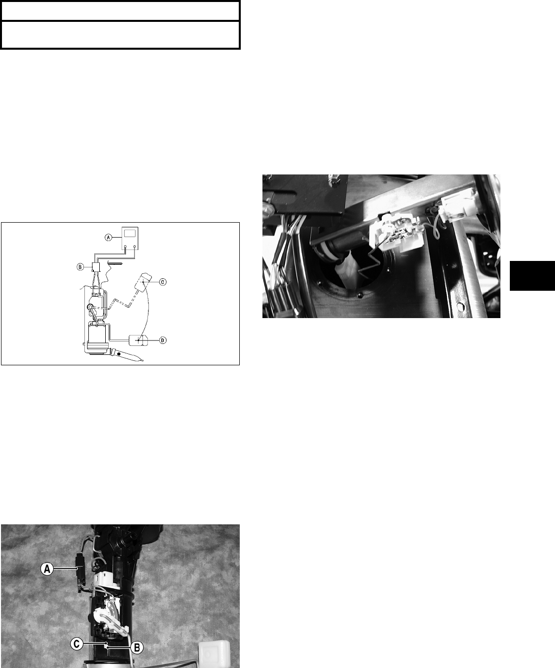
4-19
4
INSPECTING
1. Inspect the fuel screen and blow clean with low
pressure compressed air.
2. Move the float lever and check for free move-
ment. The float assembly should return to the
lower position without force. If not, replace the
fuel pump assembly.
3. Test the fuel gauge tank sensor by connecting a
multimeter (A) to the fuel sensor leads (B); then
select OHMS. The multimeter should show 5
ohms at full fuel position (C) and 95 ohms at
empty fuel position (D).
ATV2116
NOTE: If readings are erratic, clean the resistor
wiper and resistor with clean alcohol and retest. If
still not correct, replace the fuel gauge tank sensor.
4. To replace the fuel gauge tank sensor, use the
following procedure.
A. Disconnect the two-wire connector (A); then
press the fuel gauge tank sensor toward the
top of the fuel pump to release it from the
mounting slot (B).
FI460A
B. Engage the tabs (C) of the fuel gauge tank
sensor into the mounting slot (B) and press
toward the bottom of the fuel pump to latch
in place; then connect the two-wire connector
(A).
INSTALLING
1. Mark the new fuel pump with a reference mark
in the same location as the removed pump; then
place the new gasket on the pump.
2. Remove the material covering the fuel pump
opening; then carefully guide the fuel pump into
position taking care not to damage the float or
float lever.
KX190
3. Rotate the fuel pump until the match marks
align; then install the mounting screws and
tighten securely using a crisscross pattern.
NOTE: It is important to install the fuel pump
with the correct orientation to ensure adequate
float lever clearance.
4. Connect the wires, fuel hose, and spring clamp;
then turn the ignition switch to the ON position.
Note that the fuel pump runs momentarily and
the fuel gauge indicates the proper fuel level.
5. With the transmission in neutral and brake lever
lock engaged, start the engine and check for nor-
mal operation. Check for any fuel leaks.
6. Install any wire ties that were removed; then
install the rear fenders, rack, and seat making
sure the seat locks securely.
AT THIS POINT
If the pump has failed earlier test and must be
replaced, proceed to INSTALLING.
FOR ARCTIC CAT ATV DISCOUNT PARTS CALL 606-678-9623 OR 606-561-4983
www.mymowerparts.com
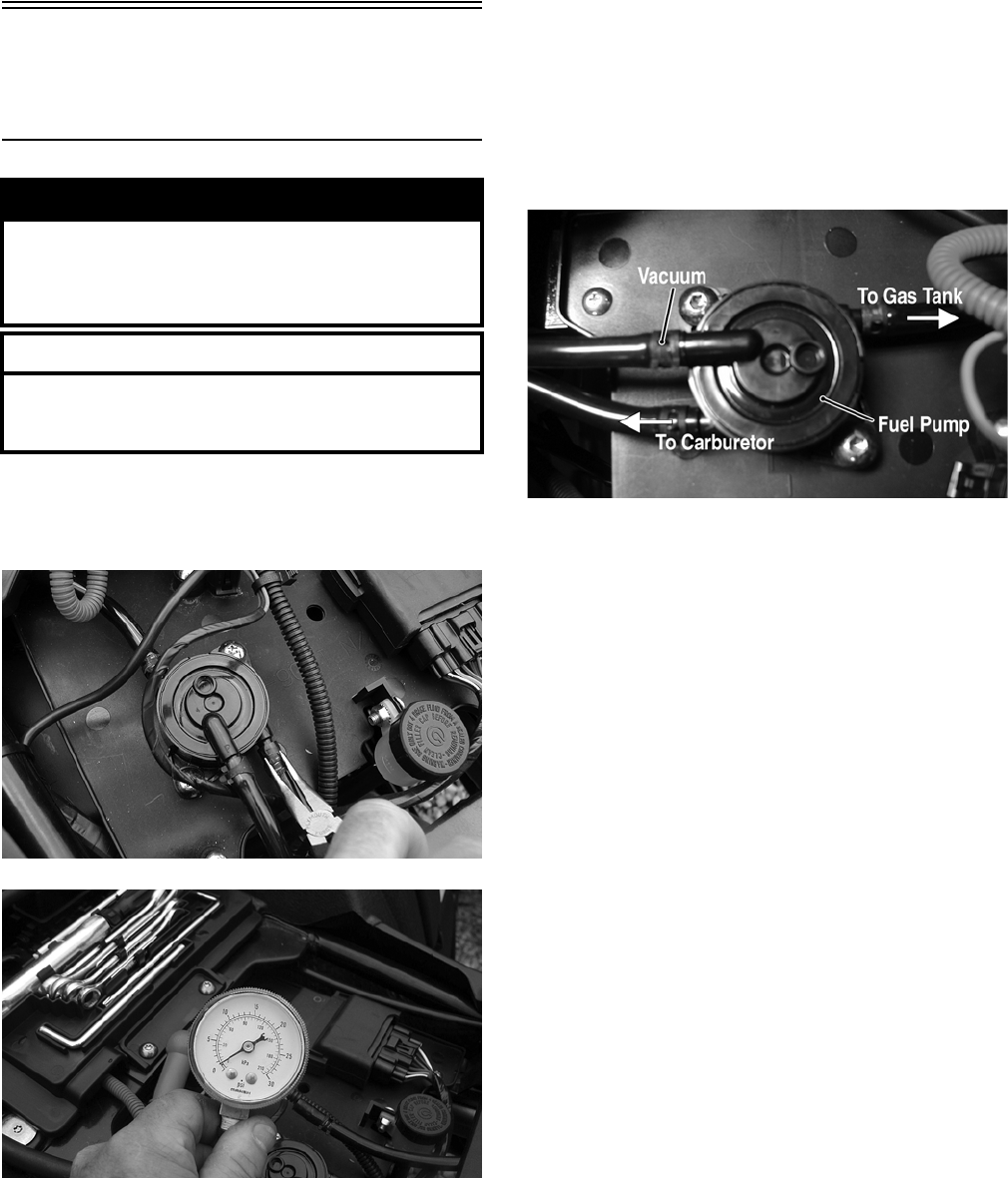
4-20
Testing Vacuum Pulse
Fuel Pump
(400/500/650 H1)
1. Disconnect the fuel pump/carburetor hose at the
fuel pump; then connect a hose and suitable
pressure gauge to the fuel pump output fitting.
CD815
CD816
2. Start the engine. Fuel pump pressure should read
0.18-0.25 kg/cm2 (2.5-3.5 psi).
REMOVING
1. Remove the seat; then remove the three clamps
securing the gas hoses and vacuum hose and dis-
connect the hoses.
CD766A
2. Remove the two machine screws and flange nuts
securing the fuel pump to the electrical tray;
then remove the pump.
INSTALLING
1. Place the fuel pump into position on the electri-
cal tray; then secure with the machine screws
and flange nuts. Tighten securely.
2. Connect two gas hoses and one vacuum hose;
then secure with the clamps.
! WARNING
Whenever any maintenance or inspection is made
on the fuel system during which there may be fuel
leakage, there should be no welding, smoking, open
flames, etc., in the area.
AT THIS POINT
Prior to removing the vacuum pulse fuel pump, the
following check should be performed to determine
that removal is necessary.
FOR ARCTIC CAT ATV DISCOUNT PARTS CALL 606-678-9623 OR 606-561-4983
www.mymowerparts.com

5-1
5
SECTION 5 —
ELECTRICAL SYSTEM
TABLE OF
CONTENTS
Specifications ………..…………….…………….…………... 5-2
Battery…………………….……………..…………….……….. 5-2
RPM Limiter.………….…………….…………….…………… 5-2
Testing Electrical Components…………..……………... 5-2
Accessory Receptacle/Connector ……………….…….. 5-3
Brakelight Switch (Auxiliary)…..…………….…………… 5-3
Brakelight Switch (Handlebar Control) ……………….. 5-3
Oil Temperature and Cooling Fan Switches (400)... 5-4
Coolant Temperature and Cooling Fan Switches
(500/650 H1) ……………….…………….…………….….. 5-5
Cooling Fan Switch and Engine Coolant
Temperature (ECT) Sensor (700 EFI) ……………… 5-5
Fan Motor …………..…………….………….…………….….. 5-6
Fuse Block/Power Distribution Module……………….. 5-6
Fuses …………..………………………..…………….……….. 5-7
Ignition Coil …………..…………….………….……………... 5-7
EFI Sensors/Components (700 EFI) ……..…………… 5-8
Electronic Speedometer Speed Sensor …….……….. 5-8
Ignition Switch …….………….…………….…………….… 5-10
Handlebar Control Switches…..…………….…………. 5-10
Front Drive Selector Switch ……………….……………. 5-11
Front Drive Selector Actuator …….……………………. 5-12
Differential Lock Switch ………………………….……… 5-12
Magneto Coils (400/500/650 H1) …….…………….… 5-13
Stator Coil/Crankshaft Position (CKP) Sensor
(700 EFI) ……………………….………….…………….… 5-14
Starter Motor …………………….…………….……………. 5-15
Starter Relay ……………….…………….…………….…… 5-20
CDI Unit (400/TBX/500/650 H1)………………………. 5-20
Electronic Control Unit (ECU) (700 EFI)……….…… 5-20
Regulator/Rectifier…….……………..…………….……… 5-21
Neutral Start/Front Drive Actuator/Start-in-Gear/
Differential Lock/2WD Relays…….……………….… 5-21
Headlights …….…………….…………….………….……… 5-21
Taillight — Brakelight …………………………….…………. 5-21
Ignition Timing………….……………..…………….……… 5-22
ECU Error Codes (700 EFI) ..…………….……………. 5-22
Tilt Sensor (700 EFI) …….…………….…………….…… 5-23
Throttle Position Sensor (TPS) (700 EFI)…..……… 5-24
FOR ARCTIC CAT ATV DISCOUNT PARTS CALL 606-678-9623 OR 606-561-4983
www.mymowerparts.com

5-2
Specifications
Battery
For battery related information, see Section 2.
RPM Limiter
NOTE: The ATV is equipped with a CDI unit that
retards ignition timing when maximum RPM is
approached. When the RPM limiter is activated, it
could be misinterpreted as a high-speed misfire.
Testing Electrical
Components
All of the electrical tests should be made using the
Fluke Model 73 Multimeter (p/n 0644-191) and when
testing peak voltage, the Peak Voltage Reading
Adapter (p/n 0644-307) must be used. If any other
type of meter is used, readings may vary due to inter-
nal circuitry. When troubleshooting a specific com-
ponent, always verify first that the fuse(s) are good,
that the bulb(s) are good, that the connections are
clean and tight, that the battery is fully charged, and
that all appropriate switches are activated.
NOTE: For absolute accuracy, all tests should be
made at room temperature of 68° F.
400
Ignition Timing 10° BTDC @ 1500 RPM
Spark Plug Type NGK CR7E
Spark Plug Gap 0.7-0.8 mm (0.028-0.032 in.)
Spark Plug Cap 8000-12,000 ohms
Ignition Coil
Resistance (primary)
(secondary)
Less than 1 ohm
(terminal to ground)
5200-7800 ohms
(high tension — plug cap
removed — to ground)
Ignition Coil
Peak Voltage (primary/
CDI)
250-375 DC volts
(terminal to ground)
MAGNETO
Magneto Coil
Resistance (trigger)
(source)
(charging)
160-240 ohms (green to blue)
Less than 1 ohm
(yellow to white)
Less than 1 ohm (black to black)
Magneto Coil
Peak Voltage (trigger)
(source)
5.04-7.56 volts (green to blue)
0.7-1.05 volts (yellow to white)
Stator Coil
Output (no load) 60 AC volts @ 5000 RPM
(black to black)
500/650 H1
Ignition Timing 10° BTDC @ 1500 RPM
Spark Plug Type NGK CR6E
Spark Plug Gap 0.7-0.8 mm (0.028-0.032 in.)
Spark Plug Cap 8000-12,000 ohms (500)
4000 ohms (650 H1)
Ignition Coil
Resistance (primary)
(secondary)
Less than 1 ohm
(terminal to ground)
5200-7800 ohms
(high tension — plug cap
removed — to ground)
Ignition Coil
Peak Voltage (primary/
CDI)
140.0-215.0 DC volts — 500
142.4-213.6 DC volts — 650 H1
(terminal to ground)
MAGNETO
Magneto Coil
Resistance (trigger)
(source)
(charging)
160-240 ohms (green to blue)
Less than 1 ohm
(yellow to white)
Less than 1 ohm (black to black)
Magneto Coil
Peak Voltage (trigger)
(source)
4.2-6.3 volts
(green to blue)
0.40-0.62 volt
(yellow to white)
Stator Coil Out-
put (no load) 60 AC volts @ 5000 RPM
(black to black)
700 EFI
Ignition Timing N/A
Spark Plug Type NGK CR6E
Spark Plug Gap 0.7-0.8 mm
(0.028-0.032 in.)
Spark Plug Cap 8000-12,000 ohms
Ignition Coil
Resistance
(primary)
(secondary)
Less than 1 ohm
(terminal (+) to terminal (-))
12k-19k ohms
(high tension — plug cap to
terminal (+))
Ignition Coil
Peak Voltage (ECU) 80 volts or more
(wire (+) to ground)
MAGNETO
Stator Coil
Resistance
(crankshaft
position
sensor)
(charging)
150-250 ohms (blue to white)
Less than 1 ohm
(yellow to yellow)
Crankshaft Position Sensor
Peak Voltage
5.0 volts or more (blue to white)
Stator Coil
Output
(no load) 75 AC volts @ 5000 RPM
(yellow to yellow)
FOR ARCTIC CAT ATV DISCOUNT PARTS CALL 606-678-9623 OR 606-561-4983
www.mymowerparts.com
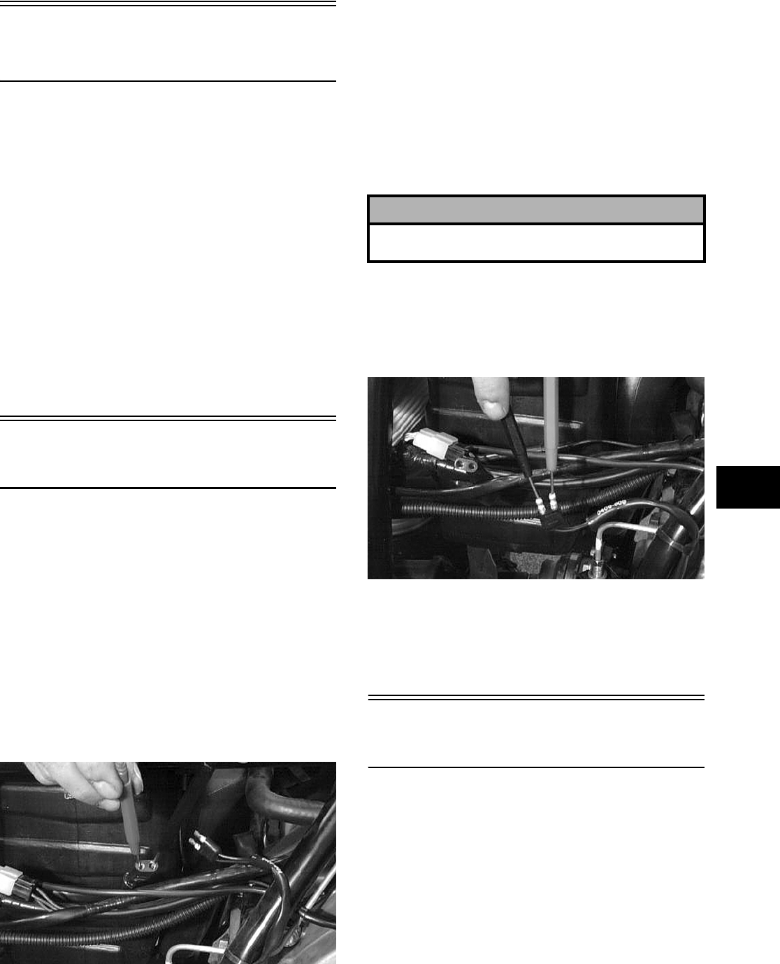
5-3
5
Accessory
Receptacle/Connector
NOTE: This test procedure is for either the
receptacle or the connector.
VOLTAGE
1. Turn the ignition switch to the ON position; then
set the meter selector to the DC Voltage posi-
tion.
2. Connect the red tester lead to the red/white wire
or the positive connector; then connect the black
tester lead to ground.
3. The meter must show battery voltage.
NOTE: If the meter shows no battery voltage,
troubleshoot the battery, fuse, receptacle, connec-
tor, or the main wiring harness.
Brakelight Switch
(Auxiliary)
The switch connector is the two-prong connector on
the brake switch lead above the transmission.
NOTE: The ignition switch must be in the ON
position.
VOLTAGE
(Wiring Harness Side)
1. Set the meter selector to the DC Voltage posi-
tion.
2. Connect the red tester to the orange wire; then
connect the black tester lead to ground.
AR627D
3. The meter must show battery voltage.
NOTE: If the meter shows no battery voltage,
troubleshoot the battery, fuse, switch, or the main
wiring harness.
NOTE: If the meter shows battery voltage, the
main wiring harness is good; proceed to test the
switch/component, the connector, and the switch
wiring harness for resistance.
RESISTANCE
(Switch Connector)
1. Set the meter selector to the OHMS position.
2. Connect the red tester lead to one black wire;
then connect the black tester lead to the other
black wire.
AR626D
3. When the brake pedal is depressed, the meter
must show less than 1 ohm.
NOTE: If the meter shows more than 1 ohm of
resistance, replace the switch.
Brakelight Switch
(Handlebar Control)
To access the connector, remove the access panel.
NOTE: The ignition switch must be in the ON
position.
VOLTAGE
(Wiring Harness Connector)
1. Set the meter selector to the DC Voltage posi-
tion.
2. Connect the red tester lead to the orange wire;
then connect the black tester lead to ground.
! CAUTION
Always disconnect the battery when performing
resistance tests to avoid damaging the multimeter.
FOR ARCTIC CAT ATV DISCOUNT PARTS CALL 606-678-9623 OR 606-561-4983
www.mymowerparts.com
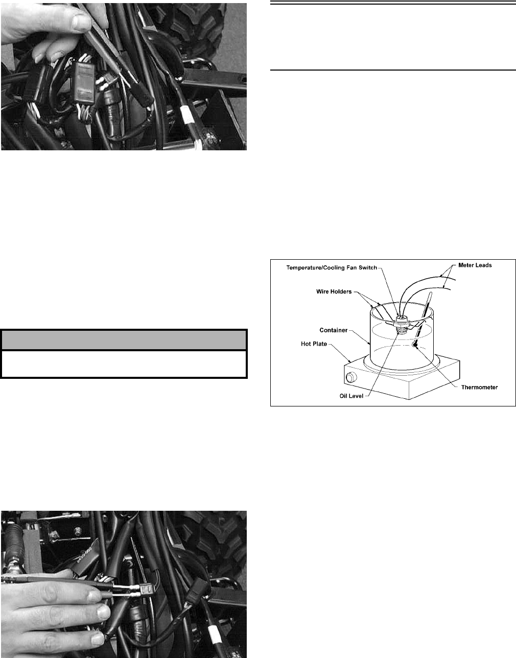
5-4
AR622D
3. The meter must show battery voltage.
NOTE: If the meter shows no battery voltage,
troubleshoot the battery, fuse, switch, or the main
wiring harness.
NOTE: If the meter shows battery voltage, the
main wiring harness is good; proceed to test the
switch/component, the connector, and the switch
wiring harness for resistance.
RESISTANCE
(Switch Connector)
NOTE: The brake lever must be compressed for
this test. Also, the ignition switch must be in the
OFF position.
1. Set the meter selector to the OHMS position.
2. Connect the red tester lead to one black wire;
then connect the black tester lead to the other
black wire.
AR621D
3. When the lever is compressed, the meter must
show less than 1 ohm.
NOTE: If the meter shows more than 1 ohm of
resistance, replace the switch.
Oil Temperature and
Cooling Fan Switches
(400)
NOTE: This model has an oil temperature switch
and a cooling fan switch.
1. Connect the meter leads (selector in the OHMS
position) to the switch contacts.
2. Suspend the switch and a thermometer in a con-
tainer of oil; then heat the oil.
NOTE: Neither the switch nor the thermometer
should be allowed to touch the bottom of the con-
tainer or inaccurate readings will occur. Use wire
holders to suspend switch and thermometer.
733-554C
3. On the oil temperature switch when the oil tem-
perature reaches 160° C (320° F), the meter
should read a closed circuit.
4. On the oil temperature switch, allow the oil to
cool, and when the temperature is at (or just
before) a temperature of 140° C (284° F), the
meter should read an open circuit.
5. On the cooling fan switch when the temperature
reaches 120° C (248° F), the meter should read a
closed circuit.
6. On the cooling fan switch, allow the oil to cool,
and when the temperature is at (or just before) a
temperature of 110° C (230° F), the meter
should read an open circuit.
7. If the readings are not as indicated, the switch
must be replaced.
8. Apply thread tape to the threads of the switch;
then install the switch and tighten securely.
9. Connect the switch leads.
! CAUTION
Always disconnect the battery when performing
resistance tests to avoid damaging the multimeter.
FOR ARCTIC CAT ATV DISCOUNT PARTS CALL 606-678-9623 OR 606-561-4983
www.mymowerparts.com
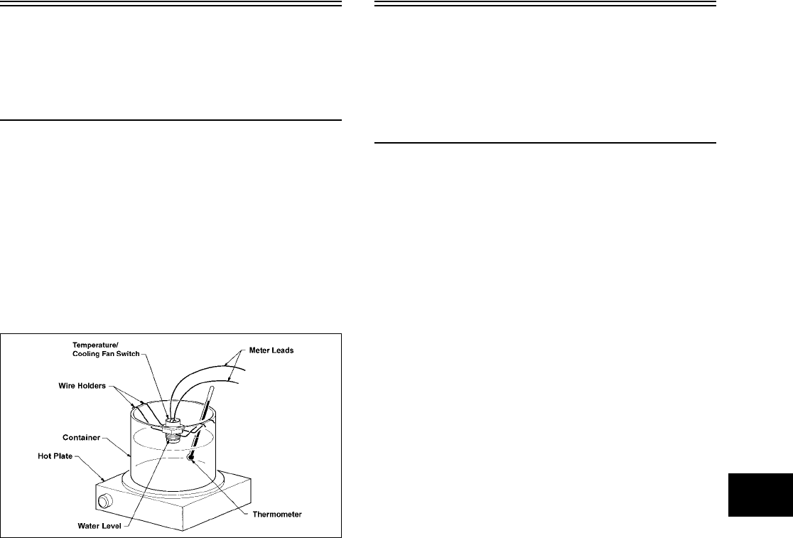
5-5
5
Coolant Temperature
and Cooling Fan
Switches
(500/650 H1)
1. Connect the meter leads (selector in the OHMS
position) to the switch contacts.
2. Suspend the switch and a thermometer in a con-
tainer of water; then heat the water.
NOTE: Neither the switch nor the thermometer
should be allowed to touch the bottom of the con-
tainer or inaccurate readings will occur. Use wire
holders to suspend switch and thermometer.
733-554E
3. On the coolant temperature switch when the
water temperature reaches 112-118° C
(234-244° F), the meter should read a closed cir-
cuit.
4. On the coolant temperature switch, allow the
water to cool, and when the temperature is
within a temperature range of 108-111° C
(226-232° F), the meter should read an open cir-
cuit.
5. On the cooling fan switch when the temperature
reaches 66-68° C (150-155° F), the meter should
read a closed circuit.
6. On the cooling fan switch, allow the water to
cool, and when the temperature is within a tem-
perature range of 62-65° C (145-149° F), the
meter should read an open circuit.
7. If the readings are not as indicated, the switch
must be replaced.
8. Install the switch and tighten securely.
9. Connect the switch leads.
Cooling Fan Switch and
Engine Coolant
Temperature (ECT)
Sensor
(700 EFI)
1. Connect the meter leads (selector in OHMS
position) to the switch/sensor terminals.
2. Suspend the switch/sensor and a thermometer in
a container of water; then heat the water.
NOTE: Neither the switch/sensor nor the ther-
mometer should be allowed to touch the bottom of
the container or inaccurate readings will occur.
Use wire holders to suspend the switch/sensor
and thermometer.
3. On the cooling fan switch when the water tem-
perature reaches approximately 93° C (199° F),
the meter should read less than 1.0 ohm.
4. On the cooling fan switch, allow the water to
cool and when the temperature reaches approxi-
mately 87° C (189° F), the meter should read an
open circuit.
5. On the ECT sensor when the temperature
reaches 20° C (68° F), the meter should read
approximately 2.45k ohms.
6. On the ECT sensor when the temperautre
reaches 50° C (122° F), the meter should read
approximately 800 ohms.
7. On the ECT sensor when the temperautre
reaches 80° C (176° F), the meter should read
approximately 318 ohms.
8. On the ECT sensor when the temperautre
reaches 110° C (230° F), the meter should read
approximately 142 ohms.
9. If the readings are not as indicated, the
switch/sensor must be replaced.
10. Install the switch/sensor and tighten securely.
11. Connect the leads.
FOR ARCTIC CAT ATV DISCOUNT PARTS CALL 606-678-9623 OR 606-561-4983
www.mymowerparts.com
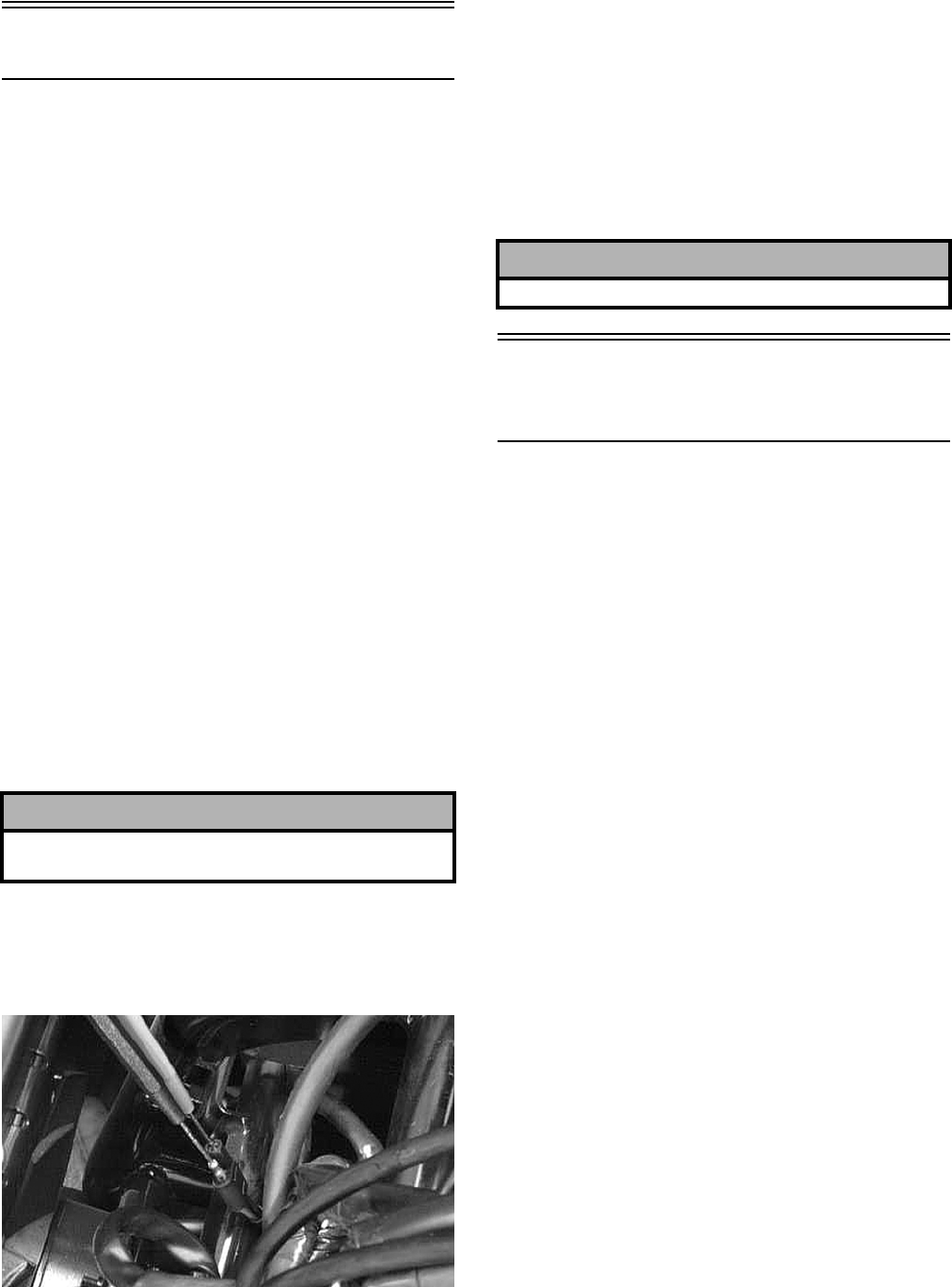
5-6
Fan Motor
The connector is the black two-prong one located
behind the fan assembly.
NOTE: The ignition switch must be in the ON
position.
VOLTAGE
(Main Harness Connector to Fan
Motor)
1. Set the meter selector to the DC Voltage posi-
tion.
2. Connect the red tester lead to the black/red wire
(500/650 H1/700 EFI) or the black/orange wire
(400); then connect the black tester lead to
ground.
3. The meter must show battery voltage.
NOTE: If the meter shows no battery voltage,
troubleshoot the battery, fuse, motor, or the main
wiring harness.
NOTE: If the meter shows battery voltage, the
main wiring harness is good. The connector
should be checked for resistance.
RESISTANCE
(Fan Motor Connector)
1. Set the meter selector to the OHMS position.
2. Connect the red tester lead to the blue wire; then
connect the black tester lead to the black wire.
AR645D
3. The meter must show less than 1 ohm.
NOTE: If the meter shows more than 1 ohm of
resistance, troubleshoot or replace the
switch/component, the connector, or the switch
wiring harness.
NOTE: To determine if the fan motor is good,
connect the blue wire from the fan connector to a
12 volt DC power supply; then connect the black
wire from the fan connector to ground. The fan
should operate.
Fuse Block/Power
Distribution Module
The fuses are located in a power distribution module
under the seat.
If there is any type of electrical system failure,
always check the fuses first.
NOTE: The ignition switch must be in the LIGHTS
position.
1. Remove all fuses from the distribution module.
2. Set the meter selector to the DC Voltage posi-
tion.
3. Connect the black tester lead to ground.
4. Using the red tester lead, contact each end of the
fuse holder connector terminals individually.
5. The meter must show battery voltage from one
side of the connector terminal ends.
NOTE: Battery voltage will be indicated from
only one side of the fuse holder connector termi-
nal; the other side will show no voltage.
NOTE: When testing the HI fuse holder, the head-
light dimmer switch must be in the HI position;
when testing the LIGHTS fuse holder, the headlight
dimmer switch can be in either position.
NOTE: If the meter shows no battery voltage,
troubleshoot the battery, switches, distribution
module, or the main wiring harness.
! CAUTION
Always disconnect the battery when performing
resistance tests to avoid damaging the multimeter.
! CAUTION
Care should be taken to keep clear of the fan blades.
FOR ARCTIC CAT ATV DISCOUNT PARTS CALL 606-678-9623 OR 606-561-4983
www.mymowerparts.com
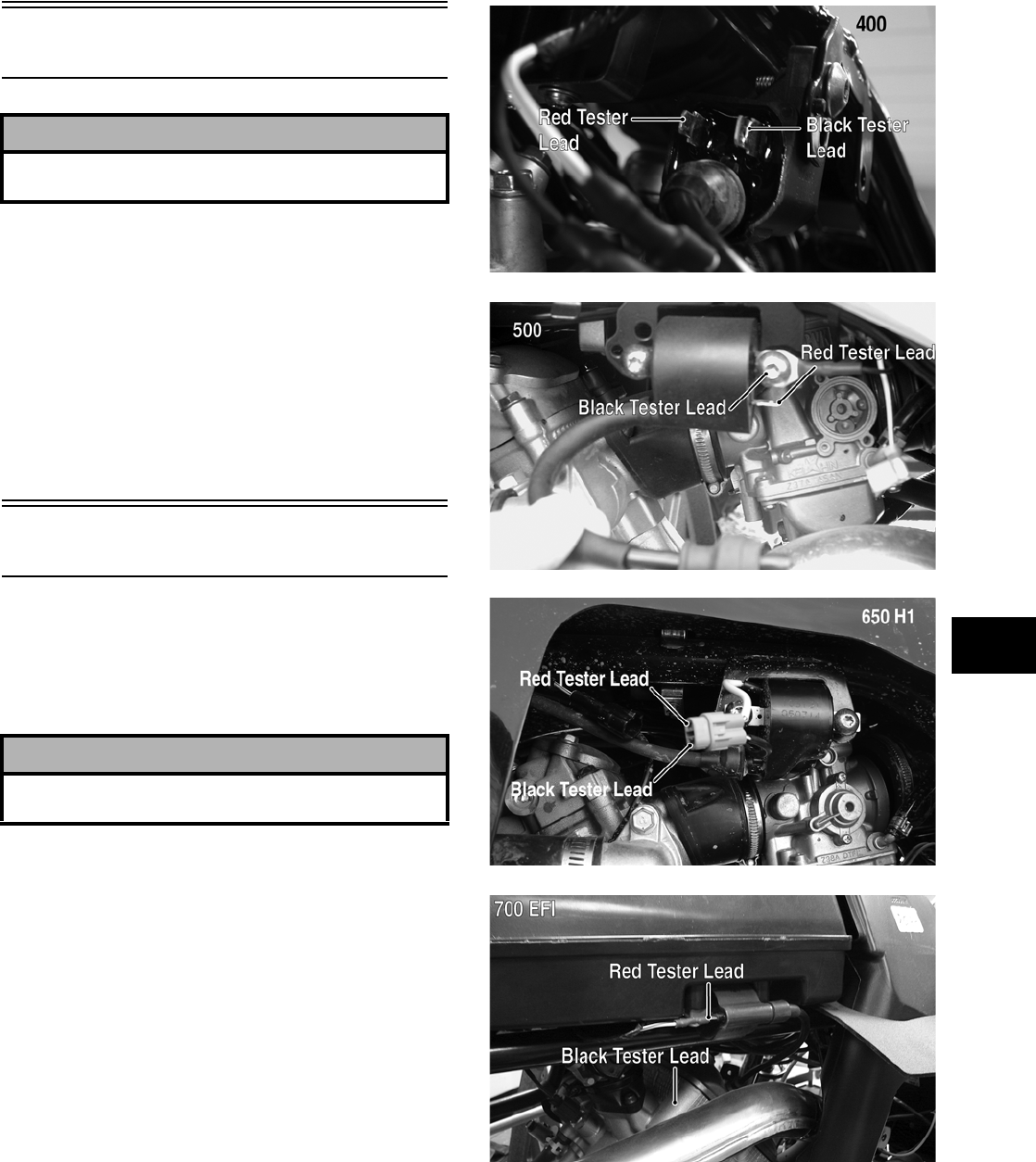
5-7
5
Fuses
1. Set the meter selector to the OHMS position.
2. Connect the red tester lead to one spade end of
the fuse; then connect the black tester lead to the
other spade end.
3. The meter must show less than 1 ohm resis-
tance. If the meter reads open, replace the fuse.
NOTE: Make sure the fuses are returned to their
proper position according to amperage. Refer to
the fuse block cover for fuse placement.
Ignition Coil
The ignition coil is on the frame above the engine.
To access the coil, the side panel (see Section 2)
must be removed.
RESISTANCE
NOTE: For these tests, the meter selector should
be set to the OHMS position and the primary
wire(s) should be disconnected.
Primary Winding
1. Connect the red tester lead to either terminal;
then connect the black tester lead to the other
terminal or on 500 models, to a suitable ground.
CF202A
CD882B
CF234A
FI066B
2. The meter reading must be within specification.
Secondary Winding
1. Remove the plug cap from the high tension lead;
then connect the red tester lead to the high ten-
sion lead.
! CAUTION
Always disconnect the battery when performing
resistance tests to avoid damaging the multimeter.
! CAUTION
Always disconnect the battery when performing
resistance tests to avoid damaging the multimeter.
FOR ARCTIC CAT ATV DISCOUNT PARTS CALL 606-678-9623 OR 606-561-4983
www.mymowerparts.com
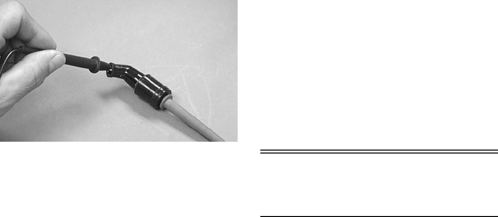
5-8
2. On the 400/650 H1, connect the black tester lead
to either primary connector; on the 500/700 EFI,
connect the black tester lead to the coil frame or
to the primary connector.
3. The meter reading must be within specification.
NOTE: If the meter does not show as specified,
replace ignition coil.
Spark Plug Cap
1. Connect the red tester lead to one end of the cap;
then connect the black tester lead to the other
end of the cap.
AR603D
2. The meter reading must be within specification.
NOTE: If the meter does not read as specified,
replace the spark plug cap.
PEAK VOLTAGE (400)
NOTE: All of the peak voltage tests should be
made using the Fluke Model 73 Multimeter (p/n
0644-191) with Peak Voltage Reading Adapter (p/n
0644-307). If any other type of tester is used, read-
ings may vary due to internal circuitry.
NOTE: The battery must be at full charge for
these tests.
Primary/CDI
NOTE: The CDI is located beneath the seat and
fender panel near the battery.
1. Set the meter selector to the DC Voltage posi-
tion; then disconnect the blue/white primary
wire from the coil.
2. Connect the red tester lead to the primary wire;
then connect the black tester lead to ground.
3. Crank the engine over using the electric starter.
4. The meter reading must be within specification.
PEAK VOLTAGE
(500/650 H1/700 EFI)
NOTE: All of the peak voltage tests should be
made using the Fluke Model 73 Multimeter (p/n
0644-191) with Peak Voltage Reading Adapter (p/n
0644-307). If any other type of tester is used, read-
ings may vary due to internal circuitry.
NOTE: The battery must be at full charge for
these tests.
Primary/CDI (500/650 H1)/
ECU (700 EFI)
NOTE: The CDI/ECU is located beneath the seat
near the battery.
1. Set the meter selector to the DC Voltage posi-
tion; then disconnect the blue/white primary
wire from the coil.
2. Connect the red tester lead to the primary wire;
then connect the black tester lead to ground.
3. Crank the engine over using the electric starter.
4. The meter reading must be within specification.
EFI Sensors/
Components
(700 EFI)
CRANKSHAFT POSITION (CKP)
SENSOR
To test the CKP sensor, see Stator Coil/Crankshaft
Position (CKP) Sensor (700 EFI) in this section.
AIR PRESSURE SENSOR (APS)
1. Disconnect the APS connector from the pressure
sensor located on the right front-side of the air
filter housing.
2. Select DC Voltage on the tester and turn the
ignition switch to the ON position.
3. Connect the black tester lead to the black/green
wire and the red tester lead to the brown wire.
The meter should read 4.5-5.5 DC volts. If the
meter does not read as specified, check the ECU
connector or wiring.
FOR ARCTIC CAT ATV DISCOUNT PARTS CALL 606-678-9623 OR 606-561-4983
www.mymowerparts.com
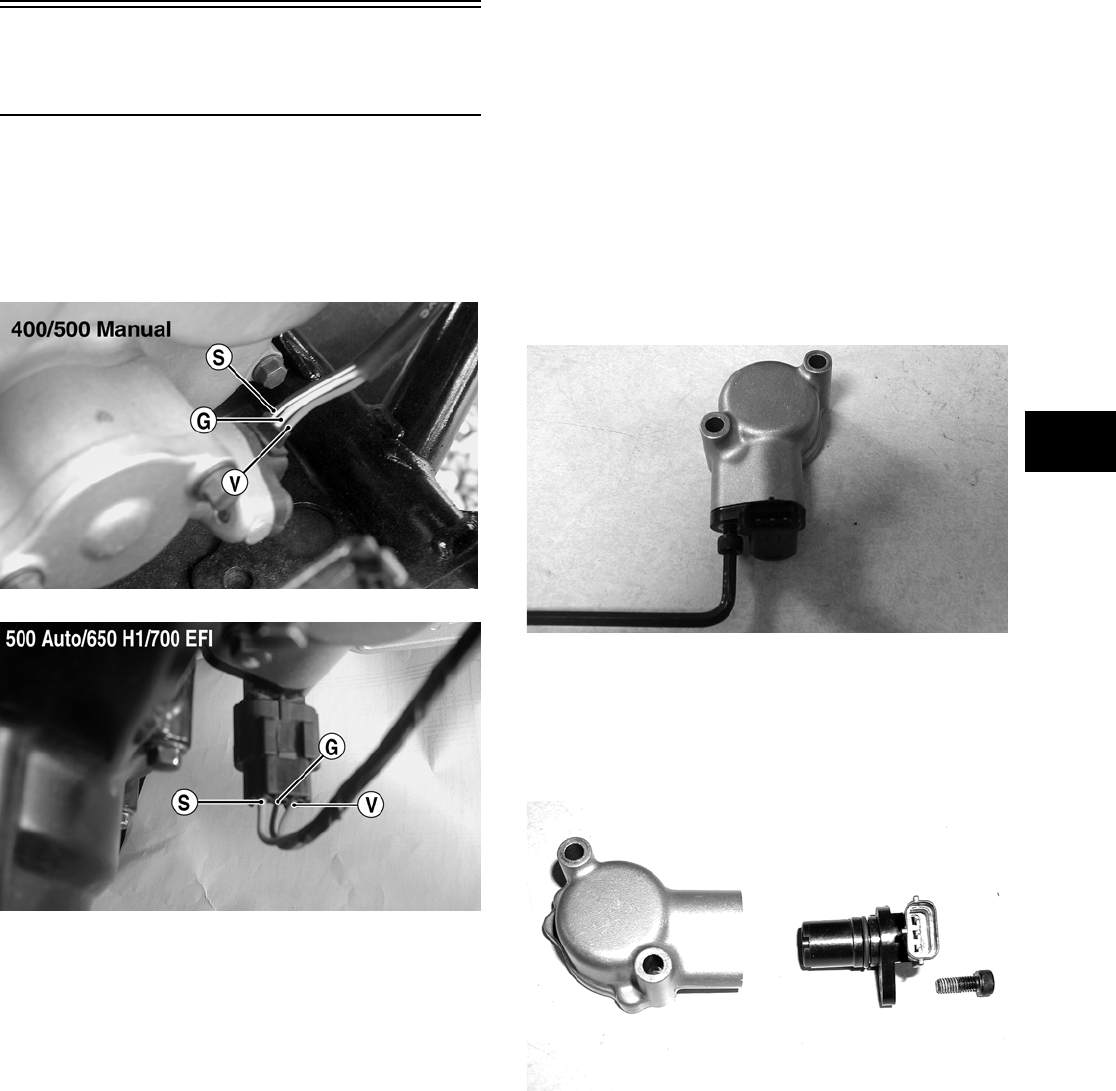
5-9
5
4. Connect the APS to the harness; then using
MaxiClips (p/n 0744-041), connect the red tester
lead to the brown/white wire and the black tester
lead to the black/green wire. With the engine
running at idle speed, the meter should read
approximately 2.6 DC volts.
NOTE: If the meter does not read as specified,
check the hose connecting the APS to the intake
pipe or replace the sensor.
Electronic Speedometer
Speed Sensor
NOTE: Prior to testing the speed sensor, inspect
the three-wire connector on the sensor harness
(400/500 manual models) or on the speed sensor
(500 auto/650 H1/700 EFI models) for contamina-
tion, broken pins, and/or corrosion.
CD884A
CD885B
1. Set the meter selector to the DC Voltage posi-
tion.
2. With appropriate needle adapters on the meter
leads, connect the red tester lead to the voltage
lead (V); then connect the black tester lead to
the ground lead (G).
3. Turn the ignition switch to the ON position.
4. The meter must show 6 DC volts (500 auto/650
H1/700 EFI) or 12 DC volts (400/500 manual).
5. Leave the black tester lead connected; then con-
nect the red tester lead to the signal lead (S) pin.
6. Slowly move the ATV forward or backward; the
meter must show 0 and 6 DC volts alternately
(500 auto/650 H1/700 EFI) or 0 and 12 DC volts
alternately (400/500 manual).
NOTE: If the sensor tests are within specifica-
tions, the speedometer must be replaced. See Sec-
tion 9.
To replace a speed sensor, use the following proce-
dure.
1. Disconnect the three-wire connector from the
speed sensor harness or from the speed sensor;
then remove the Allen-head cap screw securing
the sensor to the sensor housing.
2. Remove the sensor from the sensor housing
accounting for an O-ring.
CD070
3. Install the new speed sensor into the housing
with new O-ring lightly coated with multi-pur-
pose grease; then secure the sensor with the
Allen-head cap screw (threads coated with blue
Loctite #242). Tighten securely.
CD071
FOR ARCTIC CAT ATV DISCOUNT PARTS CALL 606-678-9623 OR 606-561-4983
www.mymowerparts.com

5-10
Ignition Switch
On the 400/500, the connector is the black
three-wire one beneath the steering post cover. On
the 650 H1/700 EFI, the connector is a four-wire
one. To access the connector, the cover must be
removed.
VOLTAGE
NOTE: Perform this test on the lower side of the
connector.
1. Set the meter selector to the DC Voltage posi-
tion.
2. Connect the red meter lead to the red wire; then
connect the black meter lead to ground.
3. Meter must show battery voltage.
NOTE: If the meter shows no battery voltage,
troubleshoot the battery or the main wiring har-
ness.
RESISTANCE
NOTE: Perform this test on the upper side of the
connector.
1. Turn the ignition switch to the ON position.
2. Set the meter selector to the OHMS position.
3. Connect the red tester lead to the red wire; then
connect the black tester lead to the orange wire
(400/500) or to the red/black wire (650 H1/700
EFI).
4. The meter must show less than 1 ohm.
5. Turn the ignition switch to the LIGHTS posi-
tion.
6. Connect the red tester lead to the red wire; then
connect the black tester lead to the orange wire
(400/500) or to the red/black wire (650 H1/700
EFI).
7. The meter must show less than 1 ohm.
8. Connect the red tester lead to the red wire; then
connect the black tester lead to the gray wire.
9. The meter must show less than 1 ohm.
10. With the switch in the OFF position, connect the
red tester lead to the red wire and the black
tester lead to each of the remaining wires. The
meter must show an open circuit on all wires.
11. On the 650 H1/700 EFI, connect the red tester
lead to the red wire and the black tester lead to
the brown wire. With the switch in the ON posi-
tion, the meter must show 980-1020 ohms.
NOTE: If the meter shows more than 1 ohm of
resistance, troubleshoot or replace the
switch/component, the connector, or the switch
wiring harness.
Handlebar Control
Switches
The connector is the yellow one next to the steering
post. To access the connector, the steering post cover
and the right-side fender splash shield must be
removed (see Section 8).
NOTE: These tests should be made on the top
side of the connector.
RESISTANCE (HI Beam)
1. Set the meter selector to the OHMS position.
2. Connect the red tester lead to the yellow wire;
then connect the black tester lead to the gray
wire.
3. With the dimmer switch in the HI position, the
meter must show less than 1 ohm.
NOTE: If the meter shows more than 1 ohm of
resistance, troubleshoot or replace the
switch/component, the connector, or the switch
wiring harness.
RESISTANCE (LO Beam)
1. Connect the red tester lead to the white wire;
then connect the black tester lead to the gray
wire.
2. With the dimmer switch in the LO position, the
meter must show an open circuit.
! CAUTION
Always disconnect the battery when performing
resistance tests to avoid damaging the multimeter.
! CAUTION
Always disconnect the battery when performing
resistance tests to avoid damaging the multimeter.
FOR ARCTIC CAT ATV DISCOUNT PARTS CALL 606-678-9623 OR 606-561-4983
www.mymowerparts.com

5-11
5
NOTE: If the meter reads resistance, trouble—
shoot or replace the switch/component, the con-
nector, or the switch wiring harness.
DIODE (Starter Button)
NOTE: If voltage is not as specified, check the
condition of the battery in the meter prior to
replacing the switch. A low battery will result in a
low voltage reading during a diode test.
1. Set the meter selector to the Diode position.
2. Connect the red tester lead to the orange/white
wire; then connect the black tester lead to the
yellow/green wire.
3. With the starter button depressed, the meter
must show 0.5-0.7 DC volts.
4. With the starter button released, the meter must
show 0 DC volts.
5. Connect the red tester lead to the yellow/green
wire; then connect the black tester lead to the
orange/white wire.
6. With the starter button depressed, the meter
must show 0 DC volts.
NOTE: If the meter does not show as specified,
replace the switch/component, connector, or
switch harness.
RESISTANCE (Emergency Stop)
1. Set the meter selector to the OHMS position.
2. Connect the red tester lead to the orange wire;
then connect the black tester lead to the
orange/white wire.
3. With the switch in the OFF position, the meter
must show an open circuit.
4. With the switch in the RUN position, the meter
must show less than 1 ohm.
NOTE: If the meter shows more than 1 ohm of
resistance, troubleshoot or replace the
switch/component, the connector, or the switch
wiring harness.
RESISTANCE (Reverse Override)
The connector is the four-prong white one next to
the steering post. To access the connector, the front
rack and front fenders must be removed (see Section
8).
1. Set the meter selector to the OHMS position.
2. Connect the red tester lead to one red/yellow
wire; then connect the black tester wire to the
other red/yellow wire. The meter must show less
than 1 ohm.
3. Depress and hold the reverse override button.
The meter must show an open circuit.
4. Connect the red tester lead to the blue wire; then
connect the black meter lead to the black wire.
The meter must show an open circuit.
5. Depress and hold the reverse override button.
The meter must show less than 1 ohm.
NOTE: If the meter does not show as specified,
replace the switch/component, connector, or
switch harness.
Front Drive Selector
Switch
The connector is the two-wire black snap-lock one
in front of the steering post. To access the connector,
the cover must be removed.
NOTE: Resistance tests should be made with the
connector disconnected and on the selector-side
of the connector.
RESISTANCE
1. Set the meter selector to the OHMS position.
2. Connect the red tester lead to the red wire; then
connect the black tester lead to the white wire.
3. With the selector switch in the 2WD position,
the meter must show a closed circuit.
4. With the selector switch in the 4WD position,
the meter must show an open circuit.
NOTE: If the meter does not show as specified,
replace the front drive selector switch.
VOLTAGE
NOTE: The battery must be connected when per-
forming voltage tests.
1. Set the meter selector to the DC Voltage posi-
tion.
! CAUTION
Always disconnect the battery when performing
resistance tests to avoid damaging the multimeter.
FOR ARCTIC CAT ATV DISCOUNT PARTS CALL 606-678-9623 OR 606-561-4983
www.mymowerparts.com
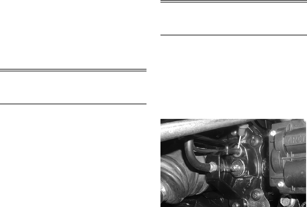
5-12
2. Connect the black tester lead to the negative bat-
tery terminal.
3. Connect the red tester lead to the red wire on the
harness side of the connector.
4. Turn the ignition switch to the RUN position.
5. The meter must show 12 DC volts.
NOTE: If the meter shows other than specified,
check the harness, connector, 30 amp fuse, and
battery connections.
Front Drive Selector
Actuator
NOTE: With the engine stopped and the ignition
switch in the ON position, a momentary “whirring”
sound must be noticeable each time the selector
switch is moved to 2WD and 4WD. Test the switch,
30 amp fuse, and wiring connections prior to test-
ing the actuator.
NOTE: The differential must be in the unlocked
position for this procedure.
VOLTAGE
1. Select the 2WD position on the front drive
selector switch; then disconnect the connector
on the actuator wiring harness.
2. With the ignition switch in the OFF position,
connect the black tester lead to the black wire in
the supply harness; then connect the red tester
lead to the orange wire in the supply harness.
3. Turn the ignition switch to the ON position. The
meter must show 12 DC volts.
4. Connect the red tester lead to the white/red wire
in the supply harness. The meter must show 12
DC volts.
5. Select the 4WD position on the front drive
selector switch; then connect the red tester lead
to the white/red wire in the supply harness. The
meter must show 0 DC volts.
NOTE: The 4WD icon on the LCD should illumi-
nate.
6. Connect the red tester lead to the orange wire in
the supply harness. The meter must show 12 DC
volts.
NOTE: If the voltage readings are as specified
and the actuator does not function correctly,
replace the actuator (see Section 6).
Differential Lock
Switch
NOTE: The following procedure does not include
the 400 TRV model.
VOLTAGE
1. Select DC Voltage on the multimeter; then con-
nect the red tester lead to the switch terminal
(leaving the wire connected) and the black tester
lead to ground.
CD575
2. Turn the ignition switch to the ON position. The
meter must show 12 DC volts.
NOTE: If no voltage is indicated, check the wiring
harness, fuse, or battery connections.
3. Select the lock position on the differential. The
meter should drop to 0 volts, and the front drive
selector actuator switch should operate to
engage 4-wheel drive.
NOTE: It may be necessary to rock the ATV
slightly to engage the differential lock fully.
NOTE: The 4WD and the LOCK icons on the LCD
should illuminate.
FOR ARCTIC CAT ATV DISCOUNT PARTS CALL 606-678-9623 OR 606-561-4983
www.mymowerparts.com
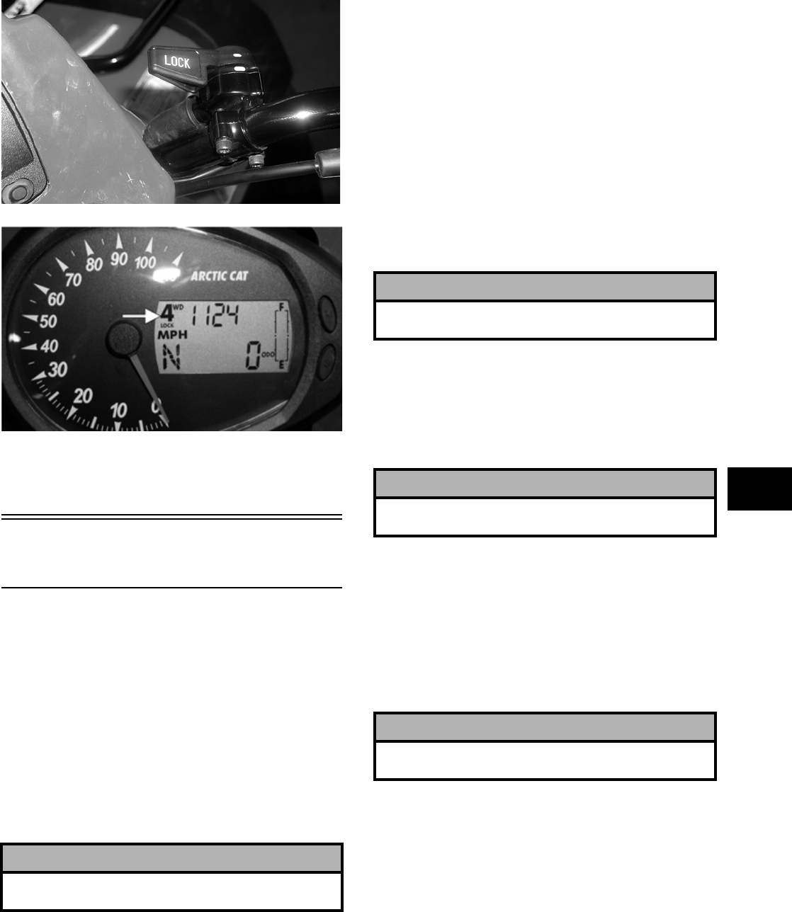
5-13
5
CD576
CF094C
4. If the differential lock engages (front wheels
locked) and the voltage does not drop to 0, the
switch is faulty and must be cleaned or replaced.
Magneto Coils
(400/500/650 H1)
VOLTAGE
(Stator Coil — Regulated Output)
1. Set the meter selector to the DC Voltage posi-
tion.
2. Connect the red tester lead to the positive bat-
tery post; then connect the black tester lead to
the negative battery post.
3. With the engine running at a constant 5000 RPM
(with the headlights on), the meter must show
14-15.5 DC volts.
NOTE: If voltage is lower than specified, test sta-
tor coil — no load.
VOLTAGE
(Stator Coil — No Load)
The connector is the black three-pin one on the right
side of the engine just above the starter motor.
NOTE: Test the connector that comes from the
engine.
1. Set the meter selector to the AC Voltage position.
2. Test between the three black wires for a total of
three tests.
3. With the engine running at the specified RPM,
all wire tests must show 60 AC volts.
NOTE: If both stator coil tests failed, check all
connections, etc., and test again. If no voltage is
present, replace the stator assembly.
RESISTANCE
(Charging Coil)
1. Set the meter selector to OHMS position.
2. Test between the three black wires for a total of
three tests.
3. The meter reading must be within specification.
RESISTANCE
(Trigger Coil)
1. Disconnect the gray four-pin connector on the
right side of the engine just above the starter
motor.
2. Set the meter selector to the OHMS position.
3. Connect the red tester lead to the green wire; then
connect the black tester lead to the blue wire. The
meter reading must be within specification.
! CAUTION
Do not run the engine at high RPM for more than 10
seconds.
! CAUTION
Do not run the engine at high RPM for more than 10
seconds.
! CAUTION
Always disconnect the battery when performing
resistance tests to avoid damaging the multimeter.
! CAUTION
Always disconnect the battery when performing
resistance tests to avoid damaging the multimeter.
FOR ARCTIC CAT ATV DISCOUNT PARTS CALL 606-678-9623 OR 606-561-4983
www.mymowerparts.com

5-14
RESISTANCE
(Source Coil)
1. Set the meter selector to the OHMS position.
2. Connect the red tester lead to the yellow wire;
then connect the black tester lead to the white
wire.
3. The meter reading must be within specification.
NOTE: If the meter shows other than specified in
any resistance test, replace the stator assembly.
PEAK VOLTAGE (400)
NOTE: All of the peak voltage tests should be
made using the Fluke Model 73 Multimeter (p/n
0644-191) with Peak Voltage Reading Adapter (p/n
0644-307). If any other type of tester is used, read-
ings may vary due to internal circuitry.
NOTE: The battery must be at full charge for
these tests.
Magneto Coil (Trigger)
1. Set the meter selector to the DC Voltage position.
2. Connect the red tester lead to the green wire; then
connect the black tester lead to the blue wire.
3. Crank the engine over using the electric starter.
4. The meter reading must be within specification.
Magneto Coil (Source)
1. Set the meter selector to the DC Voltage posi-
tion.
2. Connect the red tester lead to the yellow wire;
then connect the black tester lead to the white
wire.
3. Crank the engine over using the electric starter.
4. The meter reading must be within specification.
PEAK VOLTAGE (500/650 H1)
NOTE: All of the peak voltage tests should be
made using the Fluke Model 73 Multimeter (p/n
0644-191) with Peak Voltage Reading Adapter (p/n
0644-307). If any other type of tester is used, read-
ings may vary due to internal circuitry.
NOTE: The battery must be at full charge for
these tests.
Magneto Coil (Trigger)
1. Set the meter selector to the DC Voltage posi-
tion.
2. Connect the red tester lead to the green wire;
then connect the black tester lead to the blue
wire.
3. Crank the engine over using the electric starter.
4. The meter reading must be within specification.
Magneto Coil (Source)
1. Set the meter selector to the DC Voltage posi-
tion.
2. Connect the red tester lead to the yellow wire;
then connect the black tester lead to the white
wire.
3. Crank the engine over using the electric starter.
4. The meter reading must be within specification.
Stator Coil/Crankshaft
Position (CKP) Sensor
(700 EFI)
VOLTAGE
(Regulator/Rectifier — Output)
1. Set the meter selector to the DC Voltage posi-
tion.
2. Connect the red tester lead to the positive bat-
tery post; then connect the black tester lead to
the negative battery post.
3. With the engine running at a constant 5000 RPM
(with the headlights on), the meter must show
14-15.5 DC volts.
NOTE: If voltage is lower than specified, test sta-
tor coil — no load.
VOLTAGE
(Stator Coil — No Load)
The connector is the black three-pin one on the left
side above the shift lever.
! CAUTION
Do not run the engine at high RPM for more than 10
seconds.
FOR ARCTIC CAT ATV DISCOUNT PARTS CALL 606-678-9623 OR 606-561-4983
www.mymowerparts.com
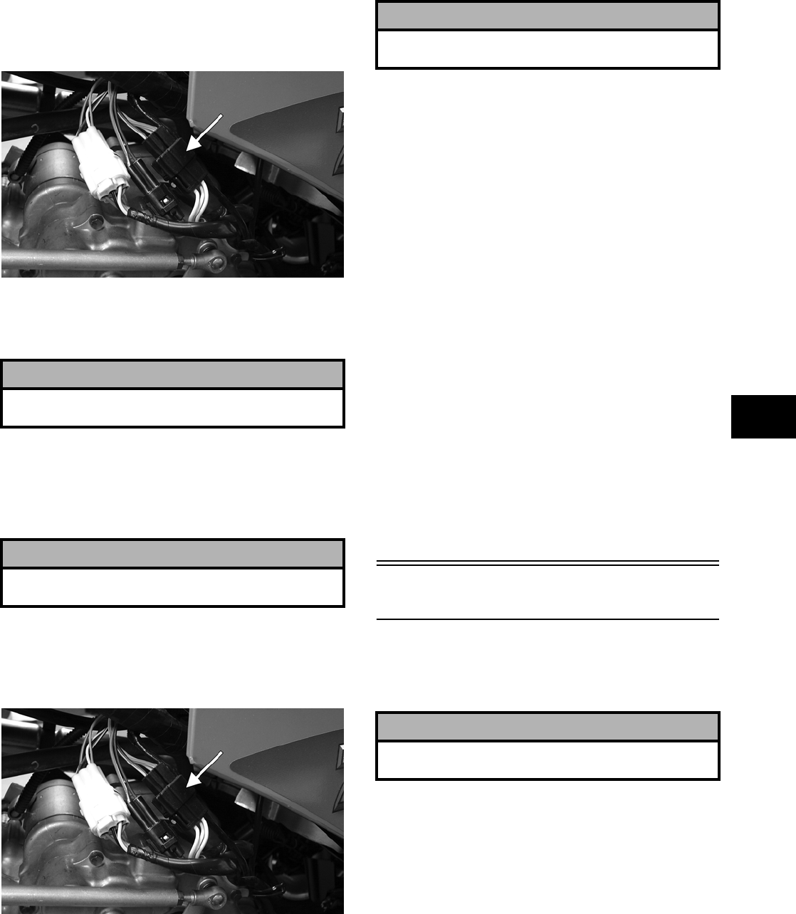
5-15
5
NOTE: Test the connector that comes from the
engine.
1. Set the meter selector to the AC Voltage posi-
tion.
2. Test between the three yellow wires for a total of
three tests.
FI083B
3. With the engine running at a constant 5000
RPM, all wire tests must be within specifica-
tions.
NOTE: If both stator coil tests failed, check all
connections, etc., and test again. If no voltage is
present, replace the stator assembly.
RESISTANCE (Charging Coil)
1. Set the meter selector to OHMS position.
2. Test between the three yellow wires for a total of
three tests.
FI083B
3. The meter reading must be within specification.
RESISTANCE
(Crankshaft Position Sensor)
1. Set the meter selector to the OHMS position.
2. Connect the red tester lead to the blue wire; then
connect the black tester lead to the white wire.
The meter reading must be within specification.
PEAK VOLTAGE
NOTE: All of the peak voltage tests should be
made using the Fluke Model 73 Multimeter (p/n
0644-191) with Peak Voltage Reading Adapter (p/n
0644-307). If any other type of tester is used, read-
ings may vary due to internal circuitry.
NOTE: The battery must be at full charge for
these tests.
Crankshaft Position Sensor
1. Set the meter selector to the DC Voltage posi-
tion.
2. Connect the red tester lead to the blue wire; then
connect the black tester lead to the white wire.
3. Crank the engine over using the electric starter.
4. The meter reading must be within specification.
Starter Motor
REMOVING/DISASSEMBLING
1. Disconnect the battery.
2. Remove the nut securing the positive cable to
the starter; then remove the cable from the
starter.
3. Remove the two cap screws securing the starter
to the crankcase; then remove the starter.
Account for the wiring forms and an O-ring.
! CAUTION
Do not run the engine at high RPM for more than 10
seconds.
! CAUTION
Always disconnect the battery when performing
resistance tests to avoid damaging the multimeter.
! CAUTION
Always disconnect the battery when performing
resistance tests to avoid damaging the multimeter.
! CAUTION
Always disconnect the negative battery cable from
the battery first; then disconnect the positive cable.
FOR ARCTIC CAT ATV DISCOUNT PARTS CALL 606-678-9623 OR 606-561-4983
www.mymowerparts.com
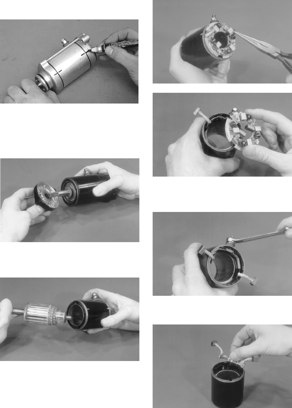
5-16
4. For assembly purposes, scribe a line across the
outside of the starter assembly.
AR652D
5. Remove the two long starter cap screws secur-
ing the starter components.
6. Remove the front cover from the starter housing
and armature shaft. Account for a seal protector
and three washers.
BC003
7. Remove the rear cover.
8. Slide the armature free of the starter housing.
BC006
9. Bend the two positive brushes outward; then
remove the brush holder.
BC007
BC010
10. Remove the nut from the positive post. Account
for the lock washer, flat washer, a fiber washer,
and an O-ring.
BC008
11. Remove the positive brush assembly from the
starter housing.
BC009
FOR ARCTIC CAT ATV DISCOUNT PARTS CALL 606-678-9623 OR 606-561-4983
www.mymowerparts.com
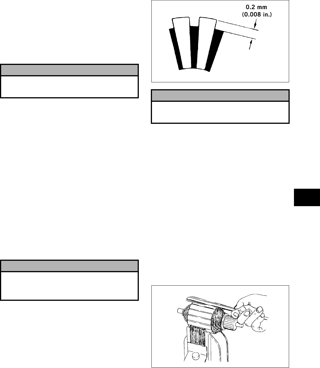
5-17
5
CLEANING AND INSPECTING
NOTE: Whenever a part is worn excessively,
cracked, or damaged in any way, replacement is
necessary.
1. Thoroughly clean all components except the
armature and brushes in parts-cleaning solvent;
then dry with compressed air.
2. Inspect all threaded areas for damage or stripped
threads.
3. Inspect the brush holder assembly and brushes
for damage or wear. Using a caliper, measure the
length of the brushes. If brush measurement is
less than 10.1 mm (0.40 in.), replace with new
brushes and brush springs as a set.
4. Inspect the brush leads for cracks, wear, or fray-
ing. If any of these conditions exist, replace with
new brushes and brush springs as a set.
5. Inspect the rear cover bushing for wear.
6. Inspect the front cover bearing for wear.
7. Inspect the brass commutator end of the arma-
ture for any discolored spots or damage. If the
commutator is lightly discolored or damaged,
the armature must be replaced. This is a molded
commutator and turning it down in a lathe
should not be attempted.
8. Inspect the commutator end of the armature for
buildup in the grooves. Carefully remove any
buildup by undercutting using a thinly ground
hacksaw blade. Do not undercut any deeper than
the original groove which can be seen by look-
ing at the end of the commutator.
9. Using a caliper, measure the undercut. Maxi-
mum undercut groove must be 0.2 mm (0.008
in.).
ATV-1054
10. Inspect the commutator for shorting using a
multimeter and the following procedure.
A. Set the selector to the OHMS position.
B. Touch the black lead to the armature shaft.
C. Using the red tester lead, probe the commuta-
tor end of the armature. The meter indicator
should not change. If the indicator shows
resistance, the armature is shorted and must
be replaced.
11. Inspect the armature for shorting using a
“growler” and the following procedure.
A. Place the armature in the “growler.”
B. While holding a metal strip on the armature,
rotate the armature an entire revolution. If the
metal strip vibrates at any point on the arma-
ture, the armature is shorted and must be
replaced.
0725-653
12. Inspect the ground brushes to make sure they are
properly grounded. Use a multimeter and the
following procedure.
A. Set the selector to the OHMS position.
! CAUTION
Do not wash the armature and brushes in any kind
of solvent. Use only compressed air and a clean dry,
lint-free cloth.
! CAUTION
Do not use emery cloth to clean the commutator as
emery particles will become imbedded in the brass
commutator resulting in a short circuit. Use only
#200 grit sandpaper.
! CAUTION
Buildup in the grooves must be removed to prevent
any chance of an electrical arc between individual
sections of the commutator.
FOR ARCTIC CAT ATV DISCOUNT PARTS CALL 606-678-9623 OR 606-561-4983
www.mymowerparts.com
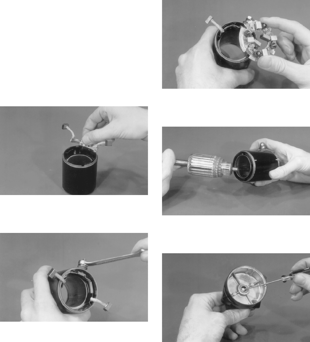
5-18
B. Touch the black tester lead to a ground brush.
C. Touch the red tester lead to the brush holder
assembly.
NOTE: If no resistance is indicated, check the
ground connection for tightness and for cleanli-
ness. If there is still no meter indication, replace
the brush assembly.
ASSEMBLING/INSTALLING
1. Install the positive post on the positive brush
assembly; then install on the starter housing.
BC009
2. On the positive post, install an O-ring washer, a
fiber washer, a flat washer, and a lock washer.
Secure with the nut.
BC008
3. Align the tab on the brush holder with the notch
in the starter housing; then install.
BC010
4. Install the armature into the starter housing; then
while holding the brushes out, slide the commu-
tator into the brush holder.
BC006
5. Apply a small amount of grease to the rear cover
bushing; then install the cover on the starter
housing making sure the reference marks align.
BC013
6. In order, install the thick metal washer, thin
metal washer, and the fiber washer on the arma-
ture shaft; then install the housing O-ring on the
starter housing.
FOR ARCTIC CAT ATV DISCOUNT PARTS CALL 606-678-9623 OR 606-561-4983
www.mymowerparts.com
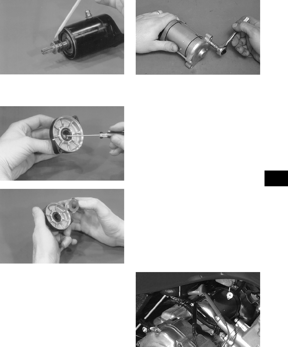
5-19
5
BC014
7. Apply a small amount of grease to the front
cover bearing and seal; then install the seal pro-
tector.
BC015
BC004
8. Place the front cover onto the starter housing
making sure it seats properly.
9. Apply red Loctite #271 to the threads of the two
long cap screws and install. Tighten to 0.8-1.2
kg-m (6-9 ft-lb).
AR653D
10. Apply a small amount of grease to the O-ring
seal on the starter; then install the starter into the
crankcase. Secure with two cap screws and wir-
ing forms.
11. Secure the positive cable to the starter with the
nut.
12. Connect the battery.
TESTING VOLTAGE
Perform this test on the starter motor positive termi-
nal. To access the terminal, slide the boot away.
NOTE: The ignition switch must be in the ON
position, the emergency stop switch in the RUN
position, the reverse lever (on manual transmis-
sion models) in the FORWARD position, and the
shift lever (on automatic transmission models) in
the NEUTRAL position.
1. Set the meter selector to the DC Voltage posi-
tion.
2. Connect the red tester lead to the starter termi-
nal; then connect the black tester lead to ground.
3. With the starter button depressed, the meter
must show battery voltage and the starter motor
should operate.
AR607D
FOR ARCTIC CAT ATV DISCOUNT PARTS CALL 606-678-9623 OR 606-561-4983
www.mymowerparts.com
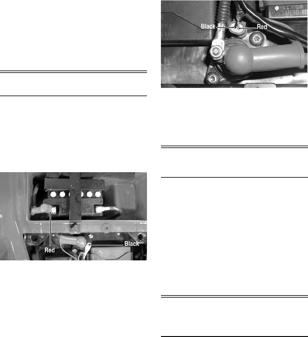
5-20
NOTE: If the meter showed battery voltage but
the starter did not operate or operated slowly,
inspect battery voltage (at the battery), starter
motor condition, and/or ground connections.
NOTE: If the meter showed no battery voltage,
inspect the main fuse, ground connections, starter
motor lead, battery voltage (at the battery), starter
relay, or the neutral start relay.
Starter Relay
1. Remove the seat; then using the multimeter set
to the DC Voltage position, check the relay as
follows.
2. Connect the red tester lead to the positive bat-
tery terminal; then connect the black tester lead
to the starter cable connection on the starter
relay. The meter must show battery voltage.
KX206A
NOTE: Make sure that the ignition switch is in
the ON position, transmission in neutral, brake
lock released, and the emergency stop switch in
the RUN position.
3. Depress the starter button while observing the
multimeter. The multimeter should drop to 0
volts and a “click” should be heard from the
relay.
NOTE: If a “click” is heard and any voltage is
indicated by the multimeter, replace the starter
relay. If no “click” is heard and the multimeter con-
tinues to indicate battery voltage, proceed to step
4.
4. Disconnect the two-wire plug from the starter
relay; then connect the red tester lead to the
green wire and the black tester lead to the black
wire.
KX059A
5. Depress the starter button and observe the multi-
meter.
NOTE: If battery voltage is indicated, replace the
starter relay. If no voltage is indicated, proceed to
Neutral Start Relay check.
CDI Unit
(400/TBX/500/650 H1)
The CDI is located beneath the seat near the battery.
NOTE: The CDI unit is not a serviceable compo-
nent. If the unit is defective, it must be replaced.
The CDI is rarely the cause for electrical problems;
however, if the CDI is suspected, substitute another
CDI unit to verify the suspected one is defective.
NOTE: Prior to replacing the CDI unit to assure
the CDI unit is defective, it is advisable to perform a
CDI peak voltage test (see Ignition Coils in this sec-
tion) and/or perform a continuity test of the wiring
harness from the CDI connector to the CDI unit.
Electronic Control
Unit (ECU)
(700 EFI)
The electronic control unit (ECU) is located beneath
the seat near the battery.
NOTE: The ECU is not a serviceable component.
If the unit is defective, it must be replaced.
The ECU is rarely the cause for electrical problems;
however, if the ECU is suspected, substitute another
ECU to verify the suspected one is defective.
FOR ARCTIC CAT ATV DISCOUNT PARTS CALL 606-678-9623 OR 606-561-4983
www.mymowerparts.com

5-21
5
Error codes can be cleared by following the proce-
dures located in the ECU Error Codes (700 EFI)
sub-section in this section.
Regulator/Rectifier
The regulator/rectifier is located under the rear rack
and rear fenders.
TESTING
1. Start engine and warm up to normal operating
temperatures; then connect a multimeter to the
battery as follows.
2. Select the DC Voltage position; then connect the
red tester lead to the positive battery post and
the black tester lead to the negative battery post.
3. Start the engine and slowly increase RPM. The
voltage should increase with the engine RPM to
a maximum of 15.5 DC volts.
NOTE: If voltage rises above 15.5 DC volts, the
regulator is faulty or a battery connection is loose
or corroded. Clean and tighten battery connec-
tions or replace the regulator/rectifier. If voltage
does not rise, check Voltage (Charging Coil — No
Load) in this section. If charging coil voltage is
normal, replace the regulator/rectifier.
Neutral Start/Front Drive
Actuator/Start-in-Gear/
Differential Lock/2WD
Relays
The relays are identical plug-in type located on the
power distribution module. Relay function can be
checked by switching relay positions. The relays are
interchangeable.
NOTE: The module and wiring harness are not a
serviceable component and must be replaced as
an assembly.
Headlights
The connectors are the four 2-prong ones secured to
the front bumper supports (two on each side) with
cable ties.
BULB VERIFICATION
(Low and High Beam)
NOTE: Perform this test on each headlight bulb.
Also, a 12-volt external power supply w/jumpers
will be needed.
1. Disconnect the wiring harness from the bulb to
be tested.
2. Connect the power supply (positive) to one bulb
contact; then connect the power supply (nega-
tive) to the remaining bulb contact.
3. The bulb should illuminate.
4. If the bulb fails to illuminate, it must be
replaced.
VOLTAGE
NOTE: Perform this test in turn on the main har-
ness side of all four connectors. Also, the ignition
switch must be in the LIGHTS position.
NOTE: The LO beam is the outside bulb, and the
HI beam is the inside bulb.
1. Set the meter selector to the DC Voltage posi-
tion.
2. Connect the red tester lead to one wire; then
connect the black tester lead to the other wire.
3. With the dimmer switch in the LO position, test
the two outside connectors (LO beam). The
meter must show battery voltage.
4. With the dimmer switch in the HI position, test
the two inside connectors (HI beam). The meter
must show battery voltage.
NOTE: If battery voltage is not shown in any test,
inspect the fuses, battery, main wiring harness,
connectors, or the left handlebar switch.
Taillight — Brakelight
The connector is the 3-prong one located under the
rear fender assembly.
BULB VERIFICATION
NOTE: Perform this test on the taillight-brake-
light side of the connector. Also, a 12-volt external
power supply (jumper) will be needed.
FOR ARCTIC CAT ATV DISCOUNT PARTS CALL 606-678-9623 OR 606-561-4983
www.mymowerparts.com
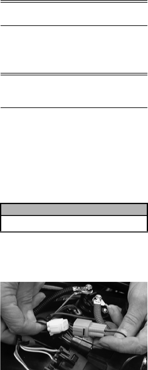
5-22
1. Connect the power supply (positive) to the mid-
dle terminal; then connect the power supply
(negative) to the bottom terminal.
2. The taillight should illuminate.
3. With the negative power supply still connected,
connect the positive supply wire to the top ter-
minal.
4. The brakelight should illuminate.
NOTE: If either the taillight or brakelight fails to
illuminate, inspect the bulb, the connectors, or the
component wiring harness.
VOLTAGE (Taillight)
NOTE: Perform this test on the main harness
side of the connector. Also, the ignition switch
should be in the LIGHTS position.
1. Set the meter selector to the DC Voltage position.
2. Connect the red tester lead to the white wire;
then connect the black tester lead to the black
wire.
3. With the ignition key in the LIGHTS position,
the meter must show battery voltage.
NOTE: If the meter shows no voltage, inspect
fuses, wiring harness, connectors, and switches.
VOLTAGE (Brakelight)
NOTE: Perform this test on the main harness
side of the connector. Also, the ignition switch
should be in the ON position and the brake (either
foot pedal or hand lever) must be applied.
NOTE: Make sure the brake lever (hand) and
brake pedal (auxiliary) are properly adjusted for
this procedure.
1. Set the meter selector to the DC Voltage posi-
tion.
2. Connect the red tester lead to the red/blue wire;
then connect the black tester lead to the black
wire.
3. With either brake applied, the meter must show
battery voltage.
NOTE: If the meter shows no voltage, inspect
bulb, fuses, wiring harness, connectors, and
switches.
Ignition Timing
The ignition timing cannot be adjusted; however,
verifying ignition timing can aid in troubleshooting
other components. To verify engine timing, see Sec-
tion 2.
ECU Error Codes
(700 EFI)
If a sensor fails or an out-of-tolerance signal is
sensed by the ECU, an error code will be generated
by the ECU. This will result in the analog needle
swinging full scale (LE model) or the LCD gauge
going blank (standard model). The EFI icon will
flash.
To read the error code, use the following procedure.
1. Make sure the ignition switch is in the OFF
position; then remove the seat.
2. Locate the diagnostic plug in front of the ECU;
then remove the black rubber cap.
3. Connect the Diagnostic Harness (p/n 0486-219)
to the diagnostic plug.
ATV-112
4. Turn the ignition switch to the ON position and
read the error code on the LCD. Refer to the fol-
lowing ECU Error Code List to identify the spe-
cific problem area.
! CAUTION
Always make sure the ignition switch is in the OFF
position before disconnecting the ECU.
FOR ARCTIC CAT ATV DISCOUNT PARTS CALL 606-678-9623 OR 606-561-4983
www.mymowerparts.com
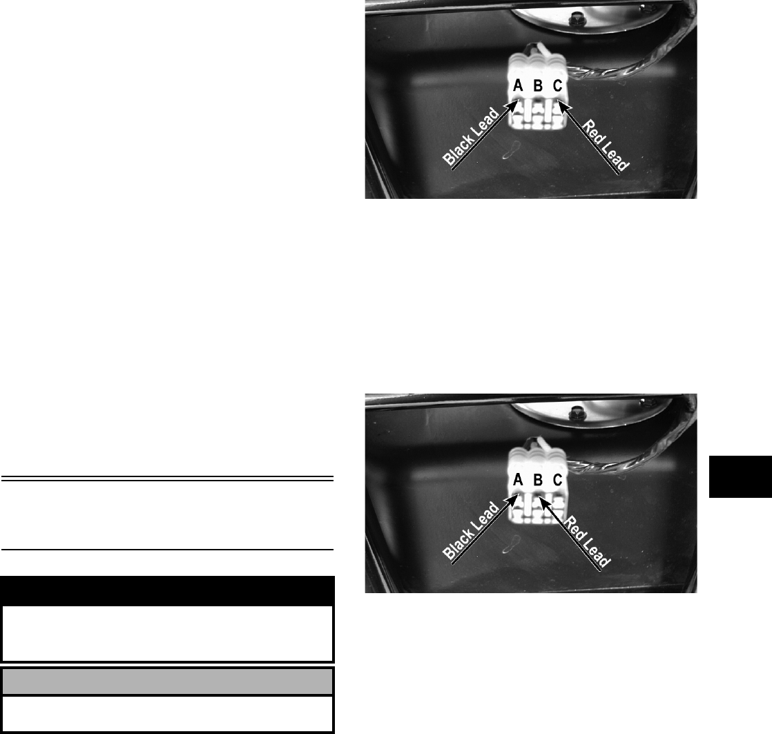
5-23
5
ECU Error Code List
• EC00 = No Fault Detected
• EC12 = CKP (Crankshaft Position) Sensor
• EC13 = APS (Air Pressure Sensor)
• EC14 = TPS (Throttle Position Sensor)
• EC15 = Water Temperature Sensor
• EC20 = Differential Lock Relay
• EC21 = Air Temperature Sensor
• EC23 = Tilt Sensor
• EC24 = Ignition Coil #1
• EC32 = Fuel Injector #1
• EC40 = ISC Valve
• EC41 = Fuel Pump Relay
• EC99 = Start Not Possible
NOTE: EC99 indicates that the engine will not
start and that the spark plug and fuel pump are
disabled. EC99 will be displayed following EC23
(Tilt Sensor), EC24 (Ignition Coil), etc.
To clear an error code after repairs or adjustments
are made, install the Diagnostic Harness (p/n
0486-219) by connecting it to the diagnostic plug;
then turn the ignition switch to the ON position.
After three seconds, turn the ignition switch to the
OFF position and disconnect the diagnostic harness.
When the ignition switch is turned on, the error code
should not be displayed.
Tilt Sensor
(700 EFI)
SUPPLY VOLTAGE
1. Disconnect the three-wire connector from the
sensor; then select DC Voltage on the multime-
ter and connect the red tester lead to the orange
wire (C) and the black tester lead to the black
wire (A).
CD706A
2. Turn the ignition switch to the ON position. The
multimeter should read battery voltage. If bat-
tery voltage is not indicated, check the 30-amp
fuse, wiring harness, or the ignition switch.
3. Remove the red tester lead and connect to the
blue/brown wire (B). The multimeter should
read 0 DC volts. If the specified voltage is not
indicated, check wire connections at the CDI or
substitute another CDI to verify the test.
CD706B
OUTPUT VOLTAGE
NOTE: Needle adapters will be required on the
multimeter leads as the following tests are made
with the sensor connected.
1. Connect the three-wire plug to the sensor; then
remove the right-side mounting screw securing
the sensor to the rear frame.
! WARNING
Incorrect installation of the tilt sensor could cause
sudden loss of engine power which could result in
loss of vehicle control resulting in injury or death.
! CAUTION
Do not drop the tilt sensor as shock can damage the
internal mechanism.
FOR ARCTIC CAT ATV DISCOUNT PARTS CALL 606-678-9623 OR 606-561-4983
www.mymowerparts.com
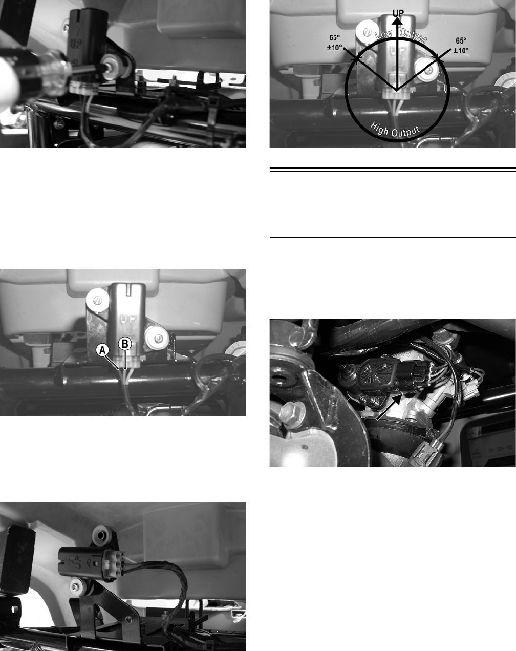
5-24
CD707
2. Install the needle adapters to the multimeter
leads; then select DC Voltage on the multimeter.
3. Connect the red tester lead to the blue/brown
wire (B) and the black tester lead to the
black/yellow wire (A); then turn the ignition
switch ON and observe the meter. The meter
should read 0.8-3.0 DC volts.
CD705B
4. Tilt the sensor 60° or more to the left and right
observing the meter. The meter should read
4.0-8.0 DC volts after approximately one second
in the tilted position. If the meter readings are
not as specified, the tilt sensor is defective.
CD709
NOTE: When replacing the sensor after testing,
make sure the arrow marking is directed up.
CD705A
Throttle Position
Sensor (TPS)
(700 EFI)
INSPECTING
1. Remove the left-side engine cover; then discon-
nect the three-wire TPS connector plug.
FI450A
NOTE: Prior to testing the TPS, inspect the
three-wire plug connector on the main harness
and the three-pin plug on the TPS for contamina-
tion, broken pins, and/or corrosion.
2. Make sure the ignition switch is in the OFF
position; then select the DC Voltage position on
the meter.
3. Connect the black tester lead to spade terminal
C and the red tester lead to spade terminal A.
Turn the ignition switch to the ON position. The
meter should read 4.5-5.5 DC volts.
FOR ARCTIC CAT ATV DISCOUNT PARTS CALL 606-678-9623 OR 606-561-4983
www.mymowerparts.com
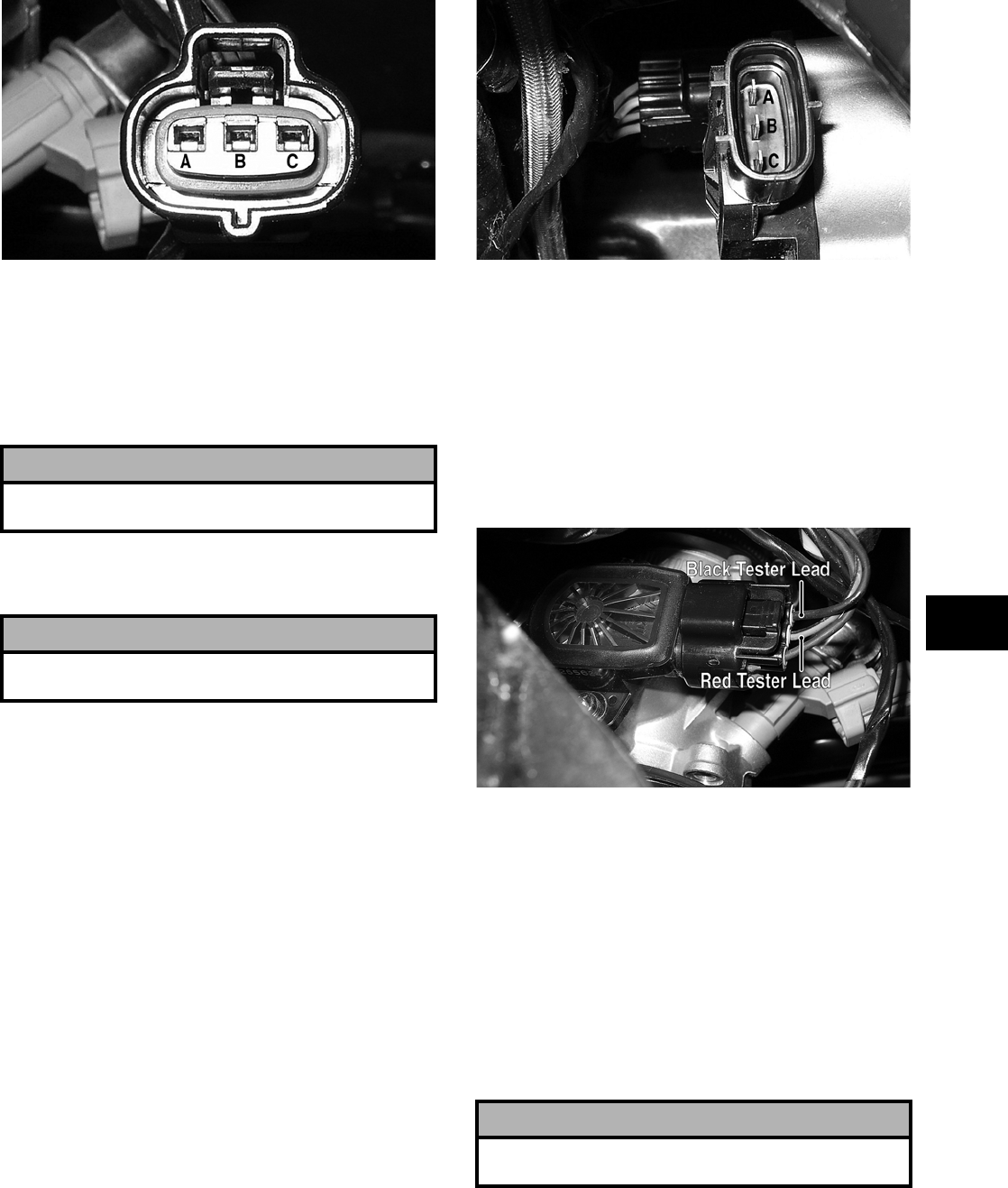
5-25
5
FI456A
4. Remove the red tester lead from spade terminal
A and connect it to spade terminal B. The meter
should read 4.5-5.5 DC volts.
NOTE: If the meter does not read as specified,
check for poor connections at the ECU or
open/broken wires in the wiring harness.
5. Turn the ignition switch to the OFF position;
then disconnect the battery (negative cable first).
6. Select the OHMS position on the meter; then
perform the following resistance tests on the
TPS.
A. Pin (B) to ground — infinity (open circuit).
B. Pin (A) to pin (B) — approximately 1.22k
ohms (throttle closed).
C. Pin (A) to pin (B) — approximately 4.36k
ohms (throttle full-open).
D. Pin (A) to pin (C) — approximately 4.05k
ohms.
FI455A
NOTE: If any meter reading is not as specified,
replace or adjust the TPS (see INSTALL-
ING/ADJUSTING in this sub-section).
7. Connect the positive lead to the battery; then
connect the negative lead.
8. Connect the main harness TPS connector to the
TPS; then using MaxiClips (p/n 0744-041), con-
nect the black tester lead to the green/black wire.
FI451A
9. Select the DC Voltage position on the meter and
turn the ignition switch to the ON position. The
meter should read approximately 1.12 DC volts
with the throttle closed and approximately 4.32
DC volts with the throttle in the full-open posi-
tion.
NOTE: If the meter readings are as specified,
check the main harness connector at the ECU
main harness wiring. If the meter readings are not
as specified, replace the TPS and adjust to specifi-
cations (see INSTALLING/ADJUSTING in this
sub-section.
10. Clear all ECU error codes after servicing is
complete (see ECU Error Codes (700 EFI) in
this section).
! CAUTION
Always make sure the ignition switch is in the OFF
position before disconnecting the ECU.
! CAUTION
Always disconnect the battery when performing
resistance tests to avoid damaging the multimeter.
! CAUTION
Always make sure the ignition switch is in the OFF
position before disconnecting the ECU.
FOR ARCTIC CAT ATV DISCOUNT PARTS CALL 606-678-9623 OR 606-561-4983
www.mymowerparts.com
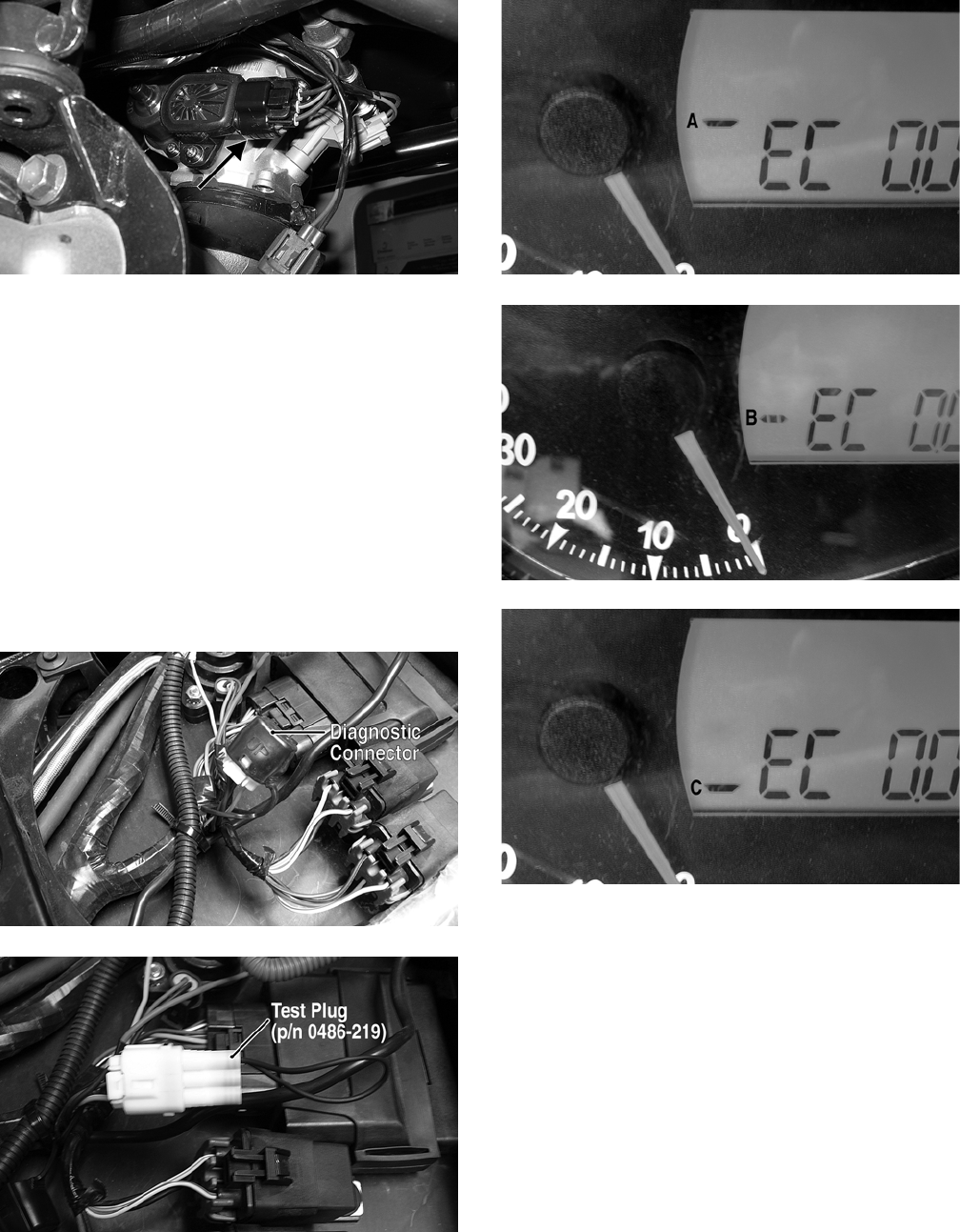
5-26
REMOVING
1. Remove the left-side engine cover; then discon-
nect the three-wire TPS connector plug.
FI450A
2. Remove the two screws securing the TPS to the
throttle body and remove the TPS.
INSTALLING/ADJUSTING
1. Place the TPS into position on the throttle body
and secure with the two screws. Do not tighten
at this time.
2. Connect the main harness to the TPS.
3. Locate the diagnostic connector under the seat;
then install the test plug from Test Plug/Error
Code List Kit (p/n 0444-216) onto the connec-
tor.
FI452A
FI453A
4. Turn the ignition switch to the ON position and
note the position of the TPS indicator icon (A,
B, or C); then adjust the TPS until the TPS icon
appears in the center position (B).
FI459A
FI454A
FI459B
5. Tighten the mounting screws securely; then ver-
ify the TPS icon appears in the center position.
6. Remove the test plug; then install the left-side
engine cover.
FOR ARCTIC CAT ATV DISCOUNT PARTS CALL 606-678-9623 OR 606-561-4983
www.mymowerparts.com

6-1
6
SECTION 6 — DRIVE SYSTEM
TABLE OF
CONTENTS
Drive System ………………….…………….………….…….. 6-2
General Information…..……………..…………….……….. 6-2
Front Drive Actuator …………..…………….……………... 6-3
Front Differential .…………….…………….…………….….. 6-4
Drive Axles ……………………….…………….……………. 6-18
Rear Gear Case …….…………….…………….…………. 6-22
Hub…………..………….…………….…………….…………. 6-24
Hydraulic Brake Caliper…………………….……………. 6-24
FOR ARCTIC CAT ATV DISCOUNT PARTS CALL 606-678-9623 OR 606-561-4983
www.mymowerparts.com

6-2
Drive System
NOTE: Some photographs and illustrations used
in this section are used for clarity purposes only
and are not designed to depict actual conditions.
NOTE: Critical torque specifications are located
in Section 10.
General Information
All gear cases are tagged beneath a cover bolt. This
tag is marked with a production date code, sequence
code, and a ratio code.
A. A “6” or “3.6” on the lower-right corner indi-
cates a 3.6:1 gear set ratio (10:36 teeth).
B. A “1” or “3.1” on the lower-right corner indi-
cates a 3.1:1 gear set ratio (11:34 teeth).
C. A “4.0” on the lower-right corner indicates a
4.0:1 gear set ratio (9:36 teeth).
The die-cast aluminum housings have been assem-
bled with thread-rolling screws (trilobular). When
assembling with these screws, start the screws care-
fully into the housing; then use the following torque
values.
SPECIFICATIONS
Specific specifications regarding the gear cases
(capacities, lubricant type, etc.) can be found in Sec-
tion 1 of this manual.
SPECIAL TOOLS
A number of special tools must be available to the
technician when servicing the gear case.
NOTE: Special tools are available from the Arctic
Cat Service Parts Department.
TROUBLESHOOTING
If a noise is heard from the gear case area, it can be
difficult to locate and/or diagnose. If the noise is
related to wheel speed, but not to engine RPM, the
problem is probably in the final drive or
engine/transmission bevel gear set. When a problem
is localized, a number of inspections must be made
to pinpoint that problem. The most obvious of the
inspections include CV boots, wheel and hub nut
tightness, wheel bearing damage, gear case lubricant
contamination, low lubricant level, seal leakage, CV
joints, or selector arm.
NOTE: Small metallic particles will collect on the
magnetic drain plug as a normal part of break-in
and will also give a metallic cast to drained lubri-
cant. Contamination would include large particles
or water which gives a “milky” look to the lubri-
cant.
NOTE: Lubricant on a new pinion housing
assembly could be grease. If the front of the gear
case is leaking at the rear drive boot, wipe excess
lubricant from the bottom of the pinion housing;
then operate the ATV for a period of time. Inspect
the pinion housing area for any signs of leakage. If
lubricant is again on the bottom of the pinion
housing, the seal must be replaced.
Additional troubleshooting could include the fol-
lowing.
• Binding/abrupt motion: CV boot torn (grease loss,
foreign object damage, broken cage); gear lubri-
cant loss or not filled (bearing seizure, broken gear
teeth, seal leakage, bladder or hose leakage,
missing filler/drain plug).
• Noise from drive system: wheel or gear case bear-
ing damage, improper gear backlash, improper
assembly, low or no gear case lubricant.
• Lockup: gear case lubricant loss or not filled, water
contamination causing bearing seizure.
Size New Housing Reassembled
Housing
M6
(Torx T-30 Recess)
1.1-1.3 kg-m
(8-9.5 ft-lb)
0.9-1.2 kg-m
(6.5-9 ft-lb)
M8
(Torx T-40 Recess)
3.5-4.3 kg-m
(25-31 ft-lb)
2.9-3.5 kg-m
(21-25 ft-lb)
M10
(Torx T-50 Recess)
5.1-6.3 kg-m
(37-45.5 ft-lb)
4.3-5.3 kg-m
(31-38 ft-lb)
Ring Gear Backlash 0.28-0.38 mm (0.011-0.015 in.)
Ring Gear End Play 0.1-0.2 mm (0.004-0.008 in.)
Description p/n
CV Boot Clamp Tool 0444-120
Pinion Gear/Shaft Removal Tool 0444-127
Slide Hammer Kit 0444-225
Internal Hex Socket (48 mm) 0444-104
FOR ARCTIC CAT ATV DISCOUNT PARTS CALL 606-678-9623 OR 606-561-4983
www.mymowerparts.com
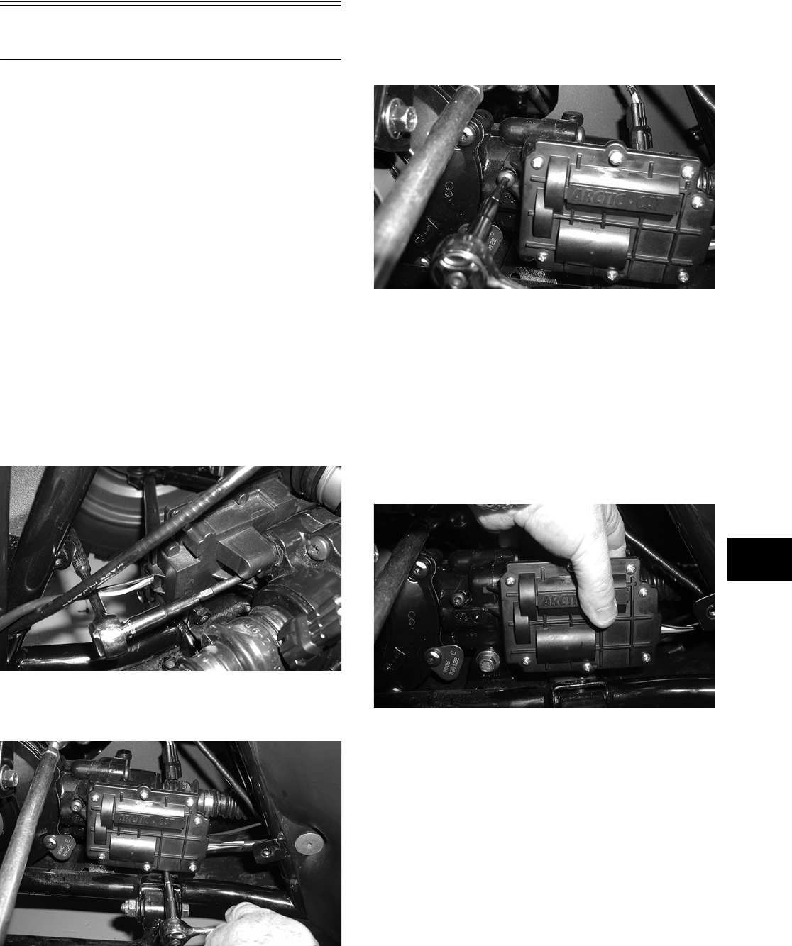
6-3
6
Front Drive Actuator
NOTE: The actuator is not a serviceable compo-
nent. If it is defective, it must be replaced.
NOTE: The actuator will operate only when the
ignition switch is in the ON position.
The front drive actuator is located on the left side of
the front drive input housing. With the engine
stopped and the ignition switch in the ON position, a
momentary “whirring” sound can be heard each
time the front drive selector switch is shifted. If no
sound is heard, see Section 5. If the actuator runs
constantly or makes squealing or grinding sounds,
the actuator must be replaced.
REMOVING
1. Remove the left-front inner fender panel; then
disconnect the connector on the actuator harness.
2. Using a T-30 torx wrench, remove the mounting
cap screw from the driveshaft side of the actuator.
AG926
3. Remove the mounting cap screw from below the
actuator on the suspension side.
AG927
4. Loosen but do not remove the mounting cap
screw at the front of the actuator; then slide the
actuator to the rear enough to clear the slotted
mounting tab and the selector shaft.
AG928
INSTALLING
1. Lubricate the O-ring on the actuator; then ensure
that all mounting surfaces are clean and free of
debris.
2. Align the actuator with the selector shaft and
slide it forward onto the shaft taking care to
engage the cap screw in the slot of the front
mounting tab.
AG925
3. While holding the actuator firmly forward,
tighten the front cap screw to hold the actuator
in place; then install but do not tighten the two
remaining cap screws.
FOR ARCTIC CAT ATV DISCOUNT PARTS CALL 606-678-9623 OR 606-561-4983
www.mymowerparts.com
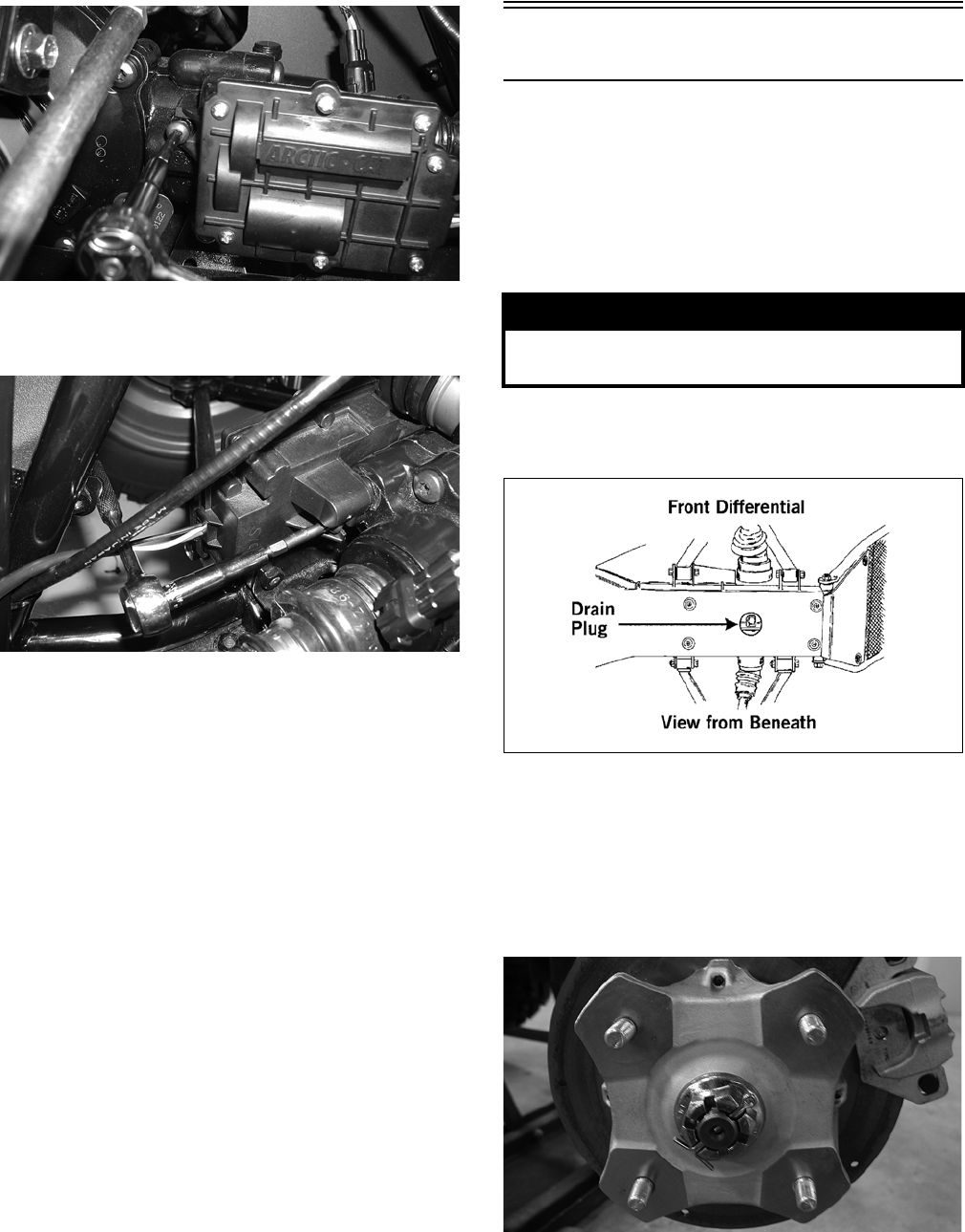
6-4
AG928
4. Loosen the front cap screw; then tighten the cap
screw on the driveshaft side.
AG926
NOTE: It is important to tighten this cap screw
while the others are loose to ensure proper seating
of the actuator.
5. Tighten the remaining cap screws; then connect
the electrical plug to the main harness.
6. Turn the ignition switch to the ON position and
check the operation by shifting the selector
switch several times.
7. Secure the wiring harness to the frame with a
nylon cable tie; then install the inner fender
panel.
Front Differential
NOTE: To remove the rear gear case, see Rear
Gear Case in this section.
REMOVING DIFFERENTIAL
1. Secure the ATV on a support stand to elevate the
wheels.
2. Remove the drain plug and drain the gear lubri-
cant into a drain pan; then reinstall the plug.
ATV0082A
3. Remove the front wheels.
4. Pump up the hand brake; then engage the brake
lever lock.
5. Remove the cotter pin securing the hex nut; then
remove the hex nut and washer.
KX041
6. Release the brake lever lock.
NOTE: It is not necessary to remove the brake
hoses from the calipers for this procedure.
! WARNING
Make sure the ATV is solidly supported on the sup-
port stand to avoid injury.
FOR ARCTIC CAT ATV DISCOUNT PARTS CALL 606-678-9623 OR 606-561-4983
www.mymowerparts.com
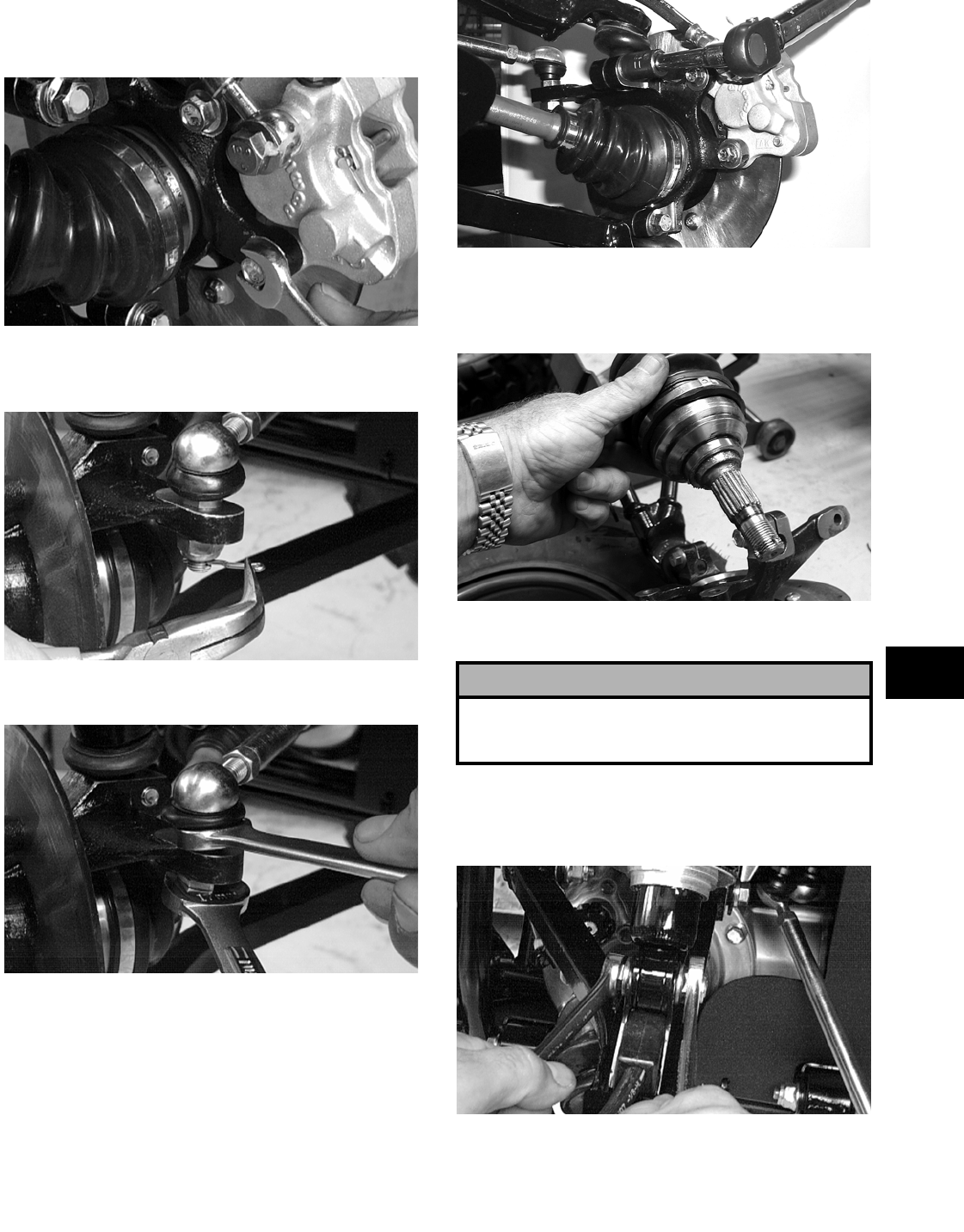
6-5
6
7. Remove the two brake calipers. Account for the
four cap screws and four 0.76 mm (0.030 in.)
spacer washers.
AF894D
8. Remove the tie rod cotter pins and discard the
pins.
AF895D
9. Remove the tie rod lock nuts.
AF896D
10. Remove the upper ball joint cap screws taking
care not to strip the threads on the ball joint
shaft; then using a rubber mallet, tap the end of
the axle and free it from the knuckle assembly.
AF628D
11. Pull the steering knuckle away from the axle
taking care not to damage the seals with the axle
end.
KX151
12. Support the axle to not allow it to drop or hang.
13. Remove the lower shock bolts. Account for the
lock nuts; then move the shocks aside and
secure them with a strap.
AF897D
14. Remove the upper A-arm lock nuts and cap
screws; then remove the A-arms.
! CAUTION
The axle must be supported. If the axle is allowed to
drop or hang, damage to the inner CV joint may
occur.
FOR ARCTIC CAT ATV DISCOUNT PARTS CALL 606-678-9623 OR 606-561-4983
www.mymowerparts.com
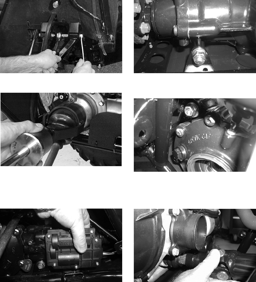
6-6
AF610D
15. Using a slide hammer, remove the front axles.
AF899D
16. Remove the inner fender panels.
17. Using a T-30 torx wrench, remove the three
screws securing the front drive actuator to the
gear case; then remove the actuator.
AG925
18. Remove the lower differential mounting cap
screw. Account for a lock nut and washers.
CD026
19. Remove the upper differential mounting cap
screws.
CD016
20. Free the differential assembly from the frame
mountings; then shift the differential assembly
forward enough to disengage the front drive-
shaft from the output yoke.
KX161
21. Place the differential on its right side; then
remove it from the frame.
FOR ARCTIC CAT ATV DISCOUNT PARTS CALL 606-678-9623 OR 606-561-4983
www.mymowerparts.com
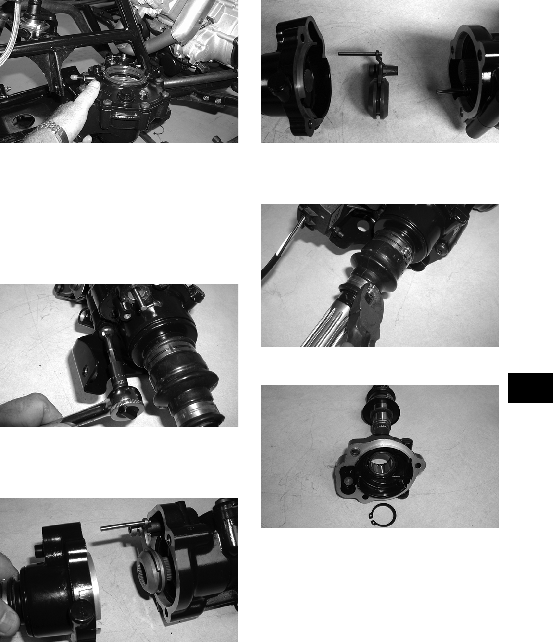
6-7
6
KX159
Disassembling Input Shaft
NOTE: This procedure can be performed on a
rear gear case; however, some components may
vary from model to model. The technician should
use discretion and sound judgment.
1. Using a T-40 torx wrench, remove the cap
screws securing the pinion housing.
CD102
2. Using a rubber mallet, remove the housing.
Account for a gasket. Remove the fork, collar,
and spring. Note the location of all the compo-
nents for assembling purposes.
CD103
CD106
3. Using a side-cutter (or suitable substitute),
remove the boot clamps; then remove the boots
and splined drive from the input shaft.
CD114
4. Remove the input shaft from the pinion housing.
CD107
5. Using a seal removal tool, remove the input
shaft seal. Account for a spacer.
FOR ARCTIC CAT ATV DISCOUNT PARTS CALL 606-678-9623 OR 606-561-4983
www.mymowerparts.com
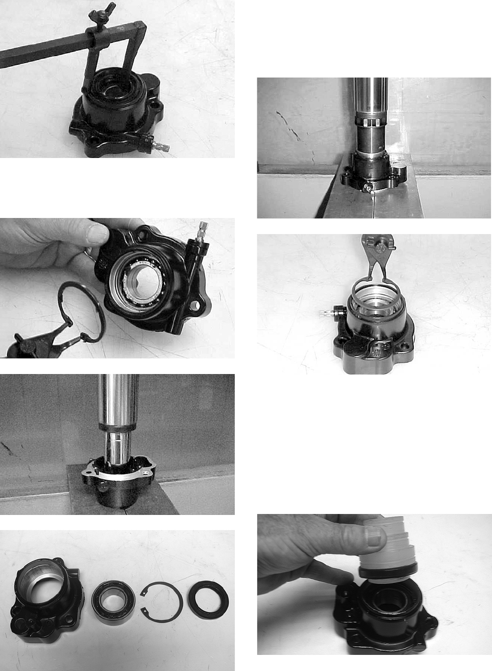
6-8
AF982
6. Remove the snap ring securing the input shaft
bearing; then place the pinion housing in a press
and remove the bearing.
AF983
AF984
KX219
Assembling Input Shaft
1. Place the pinion housing in a press and install
the input shaft bearing. Secure the bearing with
the existing snap ring making sure the sharp
edge of the snap ring faces to the outside.
AF993
AF994
2. Install the input shaft seal making sure it is flush
with the edge of the housing.
3. Lubricate the input shaft splines with High-Per-
formance Grease (p/n 0436-905).
NOTE: Any time drive splines are separated,
clean all splines with parts-cleaning solvent and
dry with compressed air; then lubricate with rec-
ommended grease.
KX221
FOR ARCTIC CAT ATV DISCOUNT PARTS CALL 606-678-9623 OR 606-561-4983
www.mymowerparts.com
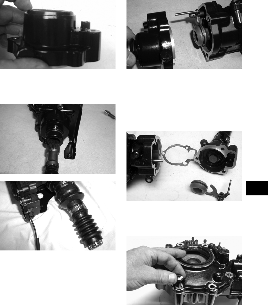
6-9
6
KX222
4. On the 400/500/650 H1, install the input shaft
into the housing; then install the front boot and
secure with Boot Clamp (p/n 0423-393) and the
rear boot with Boot Clamp (p/n 0423-411).
CD112
CD099
5. Place the pinion housing with new gasket onto
the gear case housing; then secure with the
existing cap screws. Tighten to specifications.
NOTE: If a new gear case housing is being
installed, tighten the cap screws to 3.5-4.3 kg-m
(25-31 ft-lb).
CD103
Disassembling Pinion Gear
NOTE: This procedure can be performed on a
rear gear case.
1. Using a T-40 torx wrench, remove the cap
screws securing the pinion housing. Account for
the coupler, fork, and spring.
KX209
2. Using a T-40 torx wrench, remove the cap
screws securing the gear case cover. Account for
and make note of the ID tag location for assem-
bling purposes.
KX173
3. Using a plastic mallet, tap lightly to remove the
differential cover. Account for an O-ring.
FOR ARCTIC CAT ATV DISCOUNT PARTS CALL 606-678-9623 OR 606-561-4983
www.mymowerparts.com
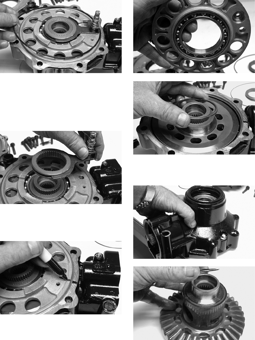
6-10
KX174
NOTE: If the cover is difficult to remove, pry on
the cover in more than one recessed location.
4. Remove the splined coupler, shifter fork, pin,
and spring of the differential lock assembly and
set aside. Note position of parts for assembling
purposes.
KX175
5. Make match marks on the left bearing housing
and differential housing; then remove the plate
and account for a shim. Mark the shim as
left-side.
KX176
KX177
KX178
6. Place the differential with the open side down;
then lift the housing off the spider assembly.
Account for shim(s) and mark as right-side.
KX179
KX181
7. Using the 48 mm Internal Hex Socket (p/n
0444-104), remove the lock collar securing the
pinion gear assembly.
FOR ARCTIC CAT ATV DISCOUNT PARTS CALL 606-678-9623 OR 606-561-4983
www.mymowerparts.com
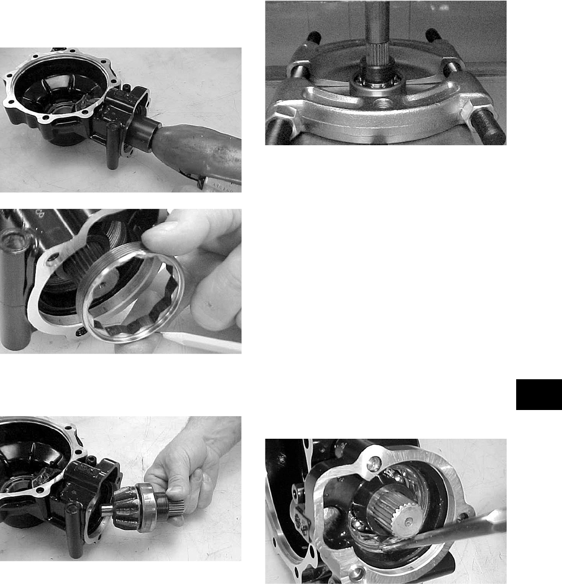
6-11
6
NOTE: On a front differential, the lock collar has
right-hand threads. On a rear gear case, the lock
collar has left-hand threads.
CC875
CC876
8. Using the Pinion Gear/Shaft Removal Tool (p/n
0444-127) and a hammer, remove the pinion
gear from the gear case housing.
CC878
9. Secure the pinion gear in a bearing puller; then
remove the pinion bearing using a press.
Account for a collar and a bearing.
CC879
NOTE: If gears are being replaced, use the exist-
ing shims. The numbers are scribed onto the
gears: the ring gear has the number on the oppo-
site side of the gears, and the pinion gear has the
number on the end of the pinion gear shaft by the
splines. If no number is present, it should be con-
sidered as being in the 0 category.
NOTE: If the gear case housing is being
replaced, proceed to the following Shimming Pro-
cedure/Shim Selection sub-section.
Shimming Procedure/Shim
Selection
1. Press bearings into bores by outer ring to hard
contact with seat.
2. Install the lock collar and tighten to specifica-
tions; then on final assembling, stake the lock
collar edge approximately 1.5 mm (0.060 in.)
into the lower oil channel.
CC891
3. Note the following shim selections (shims are
nominally 1.5 mm/0.060 in. thick):
FOR ARCTIC CAT ATV DISCOUNT PARTS CALL 606-678-9623 OR 606-561-4983
www.mymowerparts.com
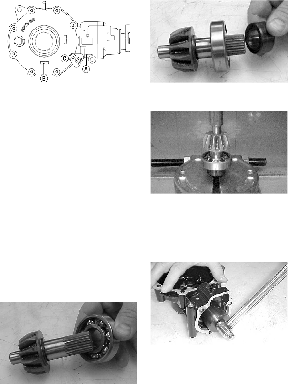
6-12
738-268B
A. Cover Side — add value A on the gear case
housing to value B (all models except 400
TRV) or value C (400 TRV) on the gear case
cover; then add 1.5 mm (0.060 in.). This will
give you the proper shim thickness.
NOTE: When shimming a rear gear case, add
value A to value B on all models.
B. Gear Case Side — install a 1.3-1.4 mm
(0.050-0.055 in.) shim and tighten the bolts to
3.5-4.3 kg-m (25-31 ft-lb). Verify backlash to
be within a range of 0.28-0.38 mm
(0.011-0.015 in.) and end-play to be within a
range of 0.10-0.20 mm (0.004-0.008 in.). If
not within specification range, reselect shim
until backlash specification range can be ver-
ified.
4. Prior to final assembling, apply molybdenum
disulfide grease to all oil seal lips.
5. Prior to final assembling, prelubricate journal on
pinion assembly with SAE 80W-90 hypoid gear
lubricant prior to pressing assembly into gear
case housing.
Assembling Pinion Gear
1. Install the bearing onto the pinion shaft. Install
the pinion shaft collar.
CC882
CC883
2. Place the pinion assembly in a bearing puller;
then install the bearing using a press.
CC884
3. Install the pinion gear assembly into the housing.
Using the 48 mm Internal Hex Socket (p/n
0444-104), secure the pinion gear assembly with
the existing lock collar. Tighten to specifications.
NOTE: On a front differential, the lock collar has
right-hand threads. On a rear gear case, the lock
collar has left-hand threads.
CC890
4. Place a punch on the edge of the lock collar in
the oil gallery area; then using a hammer, stake
the lock collar to ensure that the collar will
remain securely tightened.
FOR ARCTIC CAT ATV DISCOUNT PARTS CALL 606-678-9623 OR 606-561-4983
www.mymowerparts.com
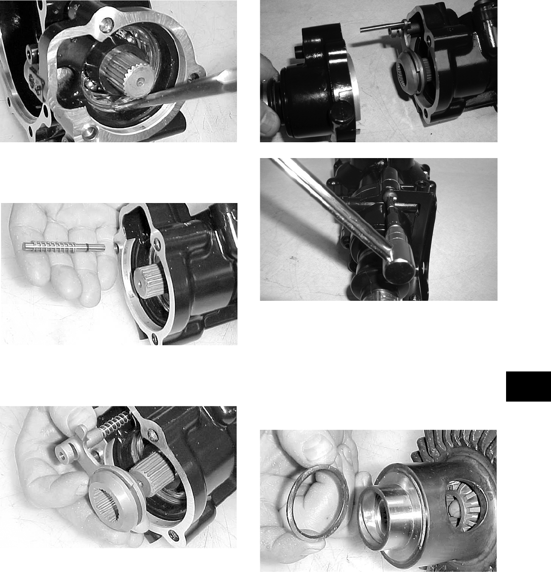
6-13
6
CC891
5. Install the shift fork shaft w/spring into the gear
housing making sure the shaft O-ring is posi-
tioned to the inside.
CC892
6. Install the shift fork assembly making sure the
fork leg is facing upward. Apply a small amount
of oil to the gasket; then install the gasket.
CC893
7. Place the input shaft assembly onto the gear
housing; then secure with the existing cap
screws. Tighten to specifications.
NOTE: If a new gear housing is being installed,
tighten the cap screws to 3.5-4.3 kg-m (25-31 ft-lb).
CD103
CD110
8. Install the proper shim onto the ring gear spider
assembly making sure the chamfer side of the
shim is facing toward the ring gear. Install the
ring gear in the housing; then install the outside
shim with the chamfer side of the shim toward
the ring gear.
NOTE: The spider and ring gear assembly must
be replaced as a complete unit.
CC896
FOR ARCTIC CAT ATV DISCOUNT PARTS CALL 606-678-9623 OR 606-561-4983
www.mymowerparts.com
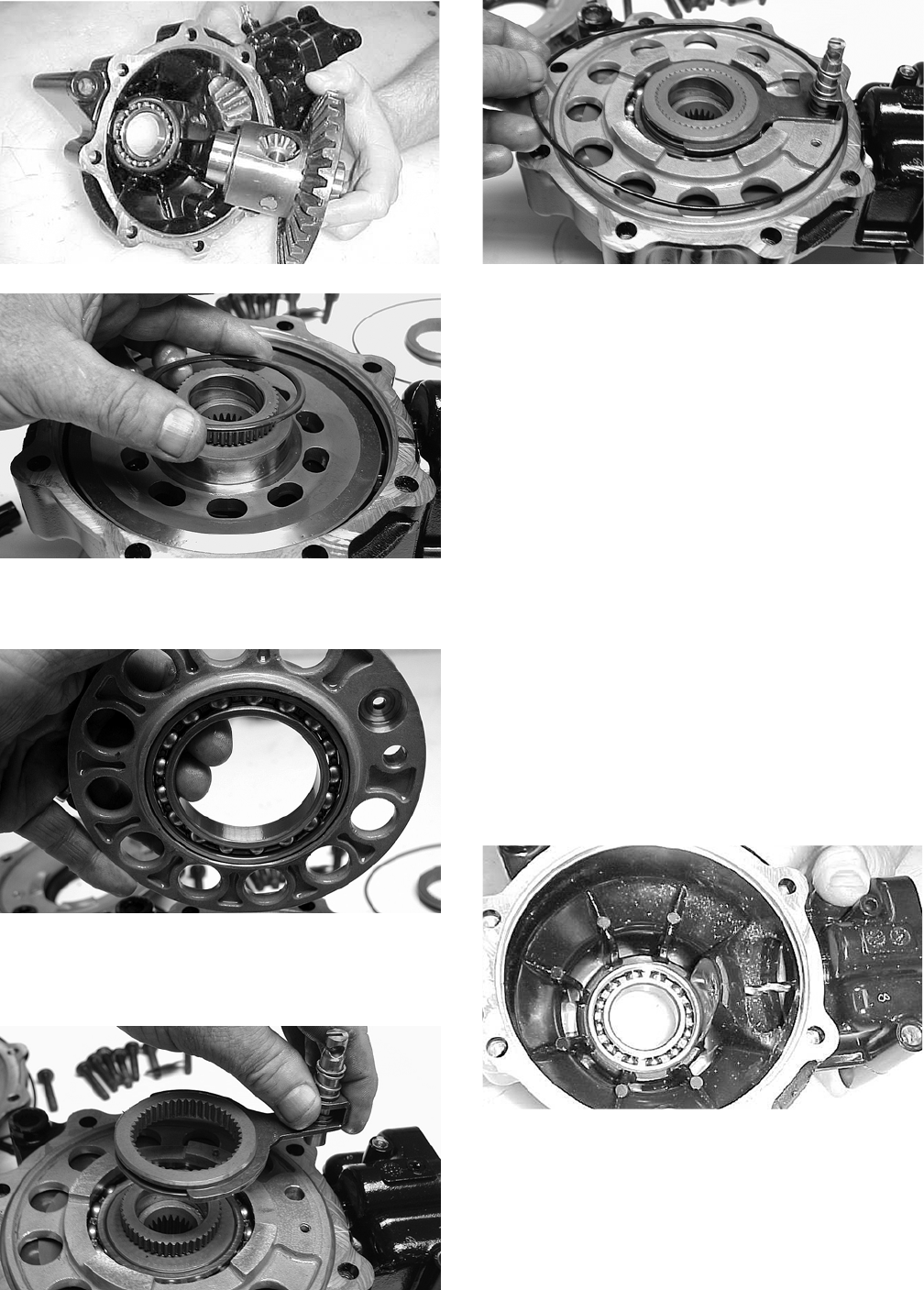
6-14
CC897
KX178
9. Install the left bearing housing aligning the match
mark to the mark on the differential housing.
KX177
10. Install the differential lock assembly into the
bearing housing; then place the O-ring on the
gear case housing.
KX175
KX174
11. Making sure the O-ring is properly positioned
on the gear case housing, install the housing
with existing hardware. Account for the ID tag.
Tighten the cap screws to specifications.
NOTE: Grease can be applied to the O-ring for
ease of assembling.
NOTE: If a new gear case housing is being
installed, tighten the cap screws to 3.5-4.3 kg-m
(25-31 ft-lb).
Removing Needle Bearing
NOTE: Removing the needle bearing is rarely
necessary. Avoid removing the needle bearing
unless the bearing is clearly damaged.
NOTE: This procedure can be performed on a
rear gear case.
1. Place a 6.35 mm (1/4 in.) drill bit on the inside
surface of the needle bearing (against the bottom
side); then drill through the pinion shaft needle
bearing housing.
CC885
2. Using a propane torch, heat the area surrounding
the needle bearing to soften the Loctite.
FOR ARCTIC CAT ATV DISCOUNT PARTS CALL 606-678-9623 OR 606-561-4983
www.mymowerparts.com
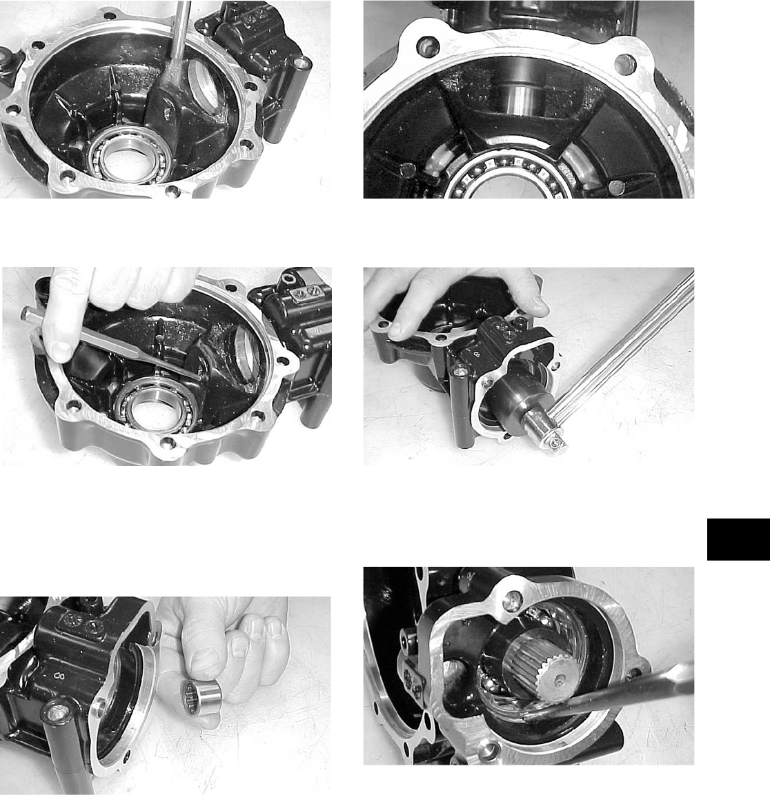
6-15
6
CC886
3. Using a flat-nosed punch, drive the bearing out
of the housing.
CC887
Installing Needle Bearing
1. Apply red Loctite #271 to the outside of a new
bearing; then place the new bearing into the
housing.
CC888
2. Using a suitable driver, install the needle bear-
ing into the gear case housing making sure the
bearing is seated.
NOTE: Do not push the bearing too far into the
housing.
CC889
3. Install the pinion shaft and secure with the exist-
ing 48 mm lock collar. Tighten to specifications.
CC890
4. Place a punch on the edge of the lock collar in
the oil gallery area; then using a hammer, stake
the lock collar to ensure that the collar will
remain securely tightened.
CC891
5. Install the pinion housing.
Removing/Installing Axle Seal
NOTE: This procedure can be performed on a
rear gear case.
1. Remove the seal using a seal removal tool.
FOR ARCTIC CAT ATV DISCOUNT PARTS CALL 606-678-9623 OR 606-561-4983
www.mymowerparts.com
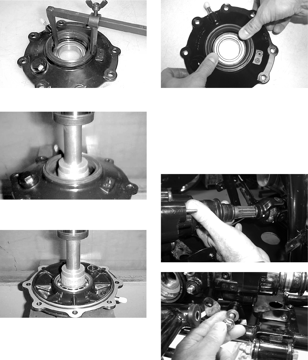
6-16
CC899
2. Using a press, remove the bearing.
CC900
3. Using a press, install the new bearing into the
housing.
CC901
NOTE: Prior to installing the seal, apply grease
to the seal outside diameter.
4. Install the seal into the housing pressing evenly
on the outside edge until the seal is seated.
CD018
5. Repeat steps 1-4 for the opposite side.
INSTALLING DIFFERENTIAL
1. Align the splined input yoke with the front out-
put splines; then place the differential into posi-
tion on the frame and install the cap screws,
washers, and flex-lock nuts. Tighten to specifi-
cations. Make sure the rubber boot is properly
seated on the input yoke.
CD857
CD859
2. Pour 275 ml (9.3 fl oz) of SAE 80W-90 hypoid
lubricant into the differential and install the
filler plug. Tighten to specifications.
3. Install the front drive actuator with the three
torx-head cap screws; then connect the wire
connector to the main wiring harness.
FOR ARCTIC CAT ATV DISCOUNT PARTS CALL 606-678-9623 OR 606-561-4983
www.mymowerparts.com
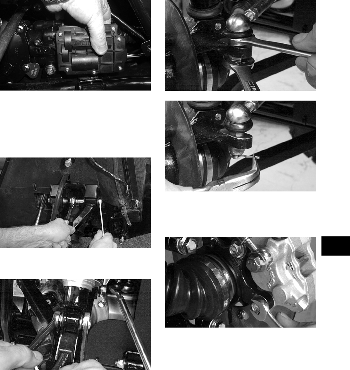
6-17
6
AG925
4. Install the inner fender panels.
5. Install the front axles (see Drive Axles in this
section).
6. Secure the upper A-arms with cap screws and
lock nuts. Tighten to specifications.
AF610D
7. Secure the lower shock eyelets with cap screws
and lock nuts. Tighten to specifications.
AF897D
8. Secure the tie rods with the lock nuts. Tighten to
specifications; then install and spread the cotter
pins.
AF896D
AF895D
9. Making sure that each caliper has the 0.76 mm
(0.030 in.) spacer washers between the caliper
and the knuckle, install the brake calipers. Secure
with the cap screws tightened to specifications.
AF894D
10. Install the wheels and tighten to specifications.
11. Remove the ATV from the support stand.
FOR ARCTIC CAT ATV DISCOUNT PARTS CALL 606-678-9623 OR 606-561-4983
www.mymowerparts.com
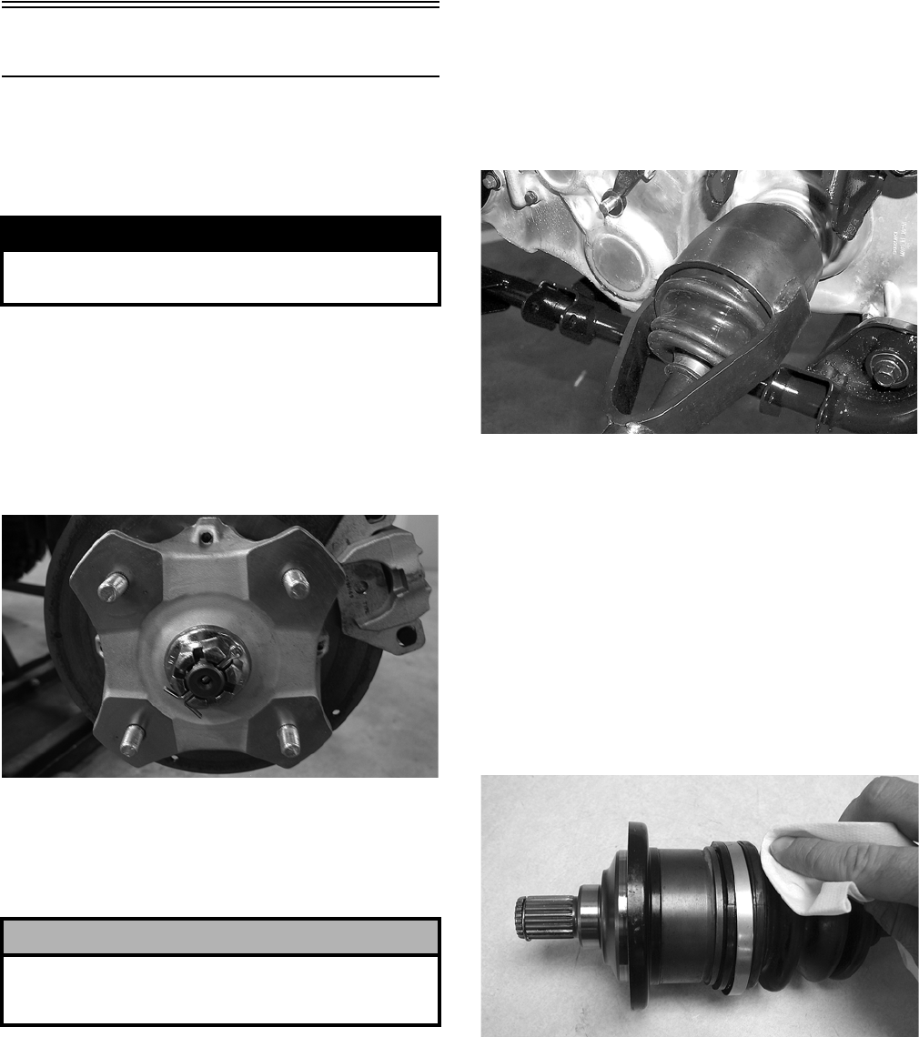
6-18
Drive Axles
REMOVING REAR DRIVE AXLE
1. Secure the ATV on a support stand to elevate the
wheels.
2. Pump up the hand brake; then engage the brake
lever lock.
3. Remove the wheel.
4. Remove the cotter pin securing the hex nut; then
remove the hex nut. Release the brake lever
lock.
KX041
5. Remove the two brake calipers (right side only).
NOTE: Do not allow the brake calipers to hang
from their cable/hose.
6. Slide the hub out of the knuckle and set aside.
7. Remove the cap screw and lock nut securing the
knuckle to the upper A-arm. Discard the lock
nut.
NOTE: Never reuse a lock nut. Once a lock nut
has been removed, it must be replaced with a new
lock nut.
8. While holding the drive axle stationary, pull the
top of the knuckle out and down until it is free of
the drive axle.
9. Place a drain pan under the ATV to contain any
oil leakage; then using a slide hammer, remove
the drive axle.
AF935
REMOVING FRONT DRIVE AXLE
NOTE: For removing a front drive axle, see Front
Differential in this section.
CLEANING AND INSPECTING
NOTE: Always clean and inspect the drive axle
components to determine if any service or replace-
ment is necessary.
1. Using a clean towel, wipe away any oil or
grease from the axle components.
CD019
2. Inspect boots for any tears, cracks, or deteriora-
tion.
NOTE: If a boot is damaged in any way, it must
be replaced with a boot kit.
3. Inspect the gear case seals for nicks or damage.
! WARNING
Make sure the ATV is solidly supported on the sup-
port stand to avoid injury.
! CAUTION
The calipers should be supported. If the calipers are
allowed to hang from the cable/hose, damage may
occur.
FOR ARCTIC CAT ATV DISCOUNT PARTS CALL 606-678-9623 OR 606-561-4983
www.mymowerparts.com
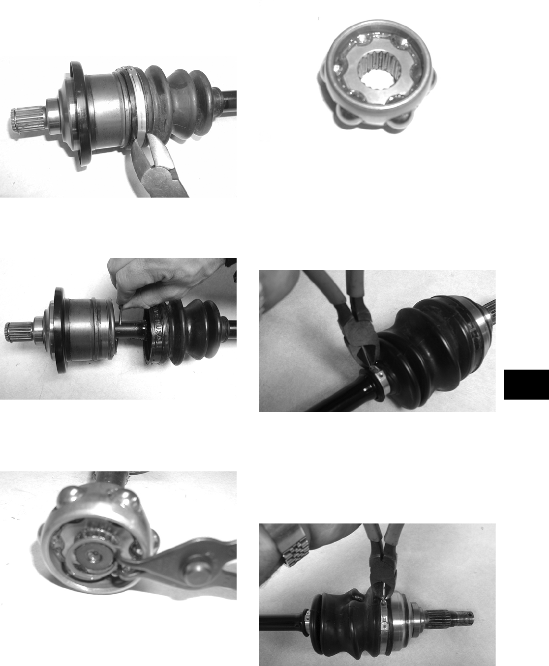
6-19
6
DISASSEMBLING AXLES
1. Using a side-cutters (or suitable substitute),
remove the large clamp from the boot.
CD020
2. Wipe away excess grease to access the retaining
ring. Using an awl or circlip pliers, remove the
circlip.
CD021
3. Using a snap ring pliers, remove the circlip
securing the bearing ring to the shaft. Note the
direction of the bearing for assembling pur-
poses.
CD023
4. Note the difference inside each bearing ring end
for assembling purposes; then remove the bear-
ing ring.
NOTE: The recess of the bearing must face
toward the housing.
CD022
5. Inspect the splines of the shaft, the bearing ring,
and the housing for damage.
NOTE: If any damage is apparent to the splines,
the bearing ring, and/or the housing, the drive axle
must be replaced as an assembly.
6. Using a side-cutters (or suitable substitute),
remove the small clamp from the shaft.
CD752
NOTE: At this point if the outside boot is dam-
aged, continue with step 7.
7. Using a side-cutters (or suitable substitute),
remove both outside boot clamps from the shaft.
Note the position of the different-sized clamps
for assembling purposes.
CD751
FOR ARCTIC CAT ATV DISCOUNT PARTS CALL 606-678-9623 OR 606-561-4983
www.mymowerparts.com
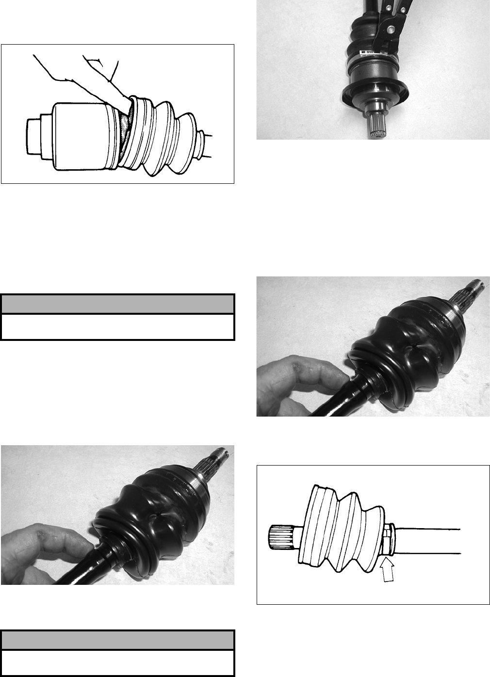
6-20
8. Apply 40 grams (1/3 of contents) of grease from
the Grease Pack (p/n 0441-173) into the knuck-
les and the new outside boot.
ATV-1052
NOTE: Grease Pack (p/n 0441-173) contains 120
grams of grease. The inside joint (double-offset)
requires approximately 70-90 grams of grease and
the outside (bell-type) requires approximately
35-55 grams. When replacing boots, use 2/3 of the
pack for inside boots and 1/3 of the pack for out-
side boots.
9. Slide the new outside boot onto the shaft with
the new clamps positioned as shown. Note the
different-sized clamps from removal.
NOTE: The boot is positioned correctly when the
small end of the boot seats down into the recessed
groove.
CD754
10. Using a CV Boot Clamp Tool (p/n 0444-120),
secure both outside boot clamps.
CD024
ASSEMBLING AXLES
1. Install the inner boot with the small clamp mak-
ing sure the ends of the clamp are positioned
correctly.
NOTE: The boot is positioned correctly when the
small end of the boot seats down into the recessed
groove.
CD754
2. Using the boot clamp pliers, secure the small
clamp of the inner boot.
ATV-1048
3. Apply 80 grams (2/3 of contents) of grease from
the pack into the bearing housing.
4. Install the bearing onto the shaft making sure the
recess of the bearing is facing the housing.
! CAUTION
Do no over-fill the joint as boot damage may occur
resulting in joint failure.
! CAUTION
It is important that the clamps are positioned cor-
rectly or they may loosen when in motion.
FOR ARCTIC CAT ATV DISCOUNT PARTS CALL 606-678-9623 OR 606-561-4983
www.mymowerparts.com
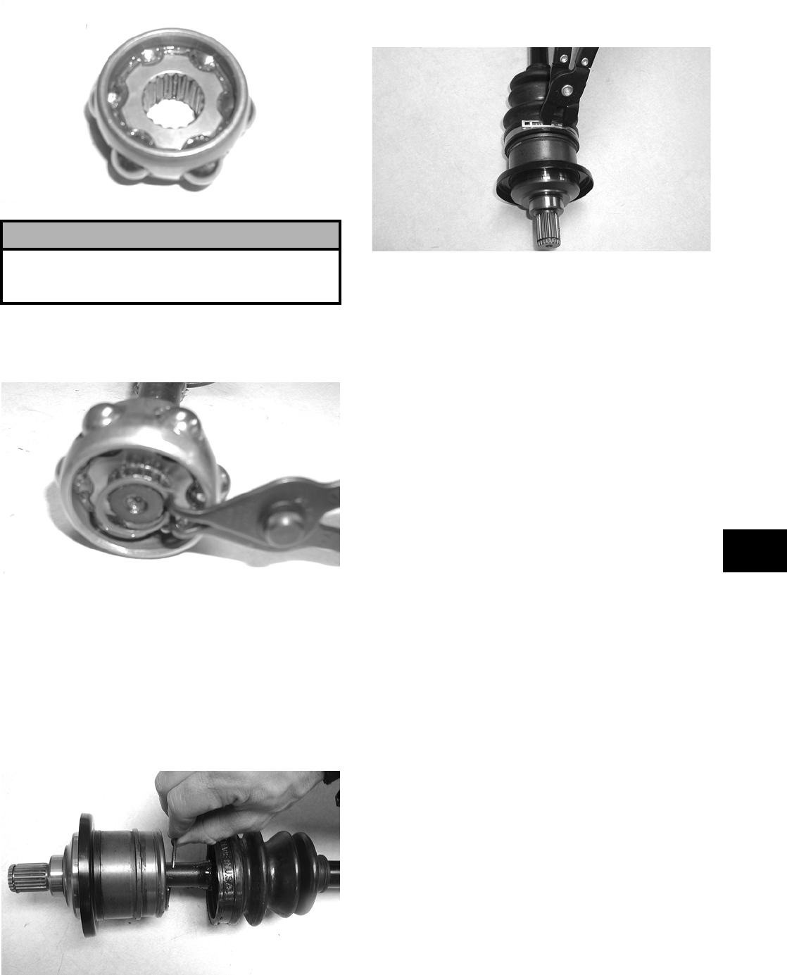
6-21
6
CD022
5. Secure the bearing ring with the circlip making
sure the sharp side of the circlip faces away
from the boot.
CD023
6. Making sure the marks made during disassem-
bling align, slide the housing over the bearing
ring; then completely seat the bearing ring into
the housing and install the circlip.
NOTE: Pull the bearing ring out of the housing
until it contacts the circlip; then slide the ring in
half way. This will purge air from the housing and
ensure the bearing is packed properly.
CD021
7. Slide the boot over the housing; then using the
boot clamp pliers, secure the boot with the clamp.
CD024
8. Inspect the axle components for correct posi-
tioning of the four clamps. Also, inspect the
boots for being correctly positioned on the shaft.
INSTALLING REAR DRIVE AXLE
1. Slide the drive axle into place in the gear case.
NOTE: To assure proper seating of the axle, give
it a light pull; the axle should remain “clipped” in
place.
2. Swing the knuckle up and onto the drive axle;
then place the knuckle into place in the upper
A-arm. Secure the knuckle to the A-arm with a
cap screw and a new lock nut. Tighten to speci-
fications.
3. Place the hub into position on the axle followed
by a hex nut. Tighten the hex nut finger-tight at
this time.
4. If the brake calipers were removed, position
them on the knuckle and secure with existing
cap screws. Tighten the auxiliary brake caliper
cap screws to specifications. Tighten the
hydraulic brake caliper cap screws to specifica-
tions.
5. Pump up the hand brake lever; then engage the
brake lever lock.
6. Tighten the hub hex nut (from step 3) to specifi-
cations; then install and spread a new cotter pin
making sure each side of the pin is flush to the
hub nut.
! CAUTION
The bearing ring must go onto the shaft with the
side without splines facing toward the small clamp
of the inner boot or severe damage will result.
FOR ARCTIC CAT ATV DISCOUNT PARTS CALL 606-678-9623 OR 606-561-4983
www.mymowerparts.com
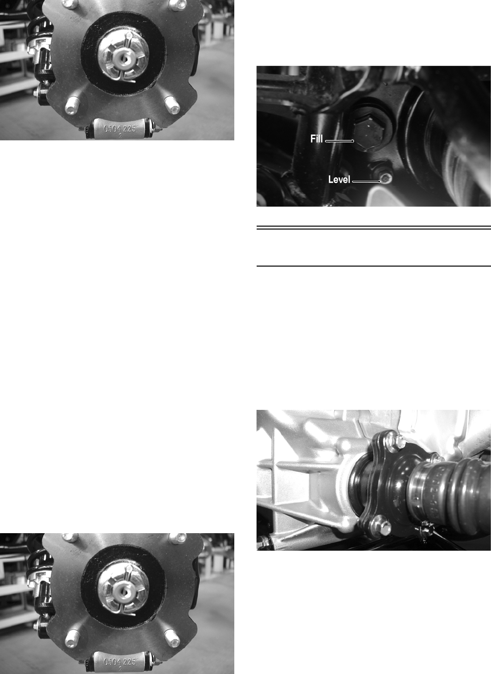
6-22
CD027
7. Install the wheel. Tighten to specifications.
8. Remove the ATV from the support stand and
release the brake lever lock.
INSTALLING FRONT DRIVE AXLE
1. Position the drive axle in the gear case and steer-
ing knuckle; then insert the upper A-arm ball
joint into the steering knuckle. Secure with a cap
screw tightened to specifications.
2. Place the brake hose into position on the upper
A-arm; then secure the lower shock eyelet to the
A-arm with a cap screw and a new lock nut.
Tighten to specifications.
3. Secure the tie rod to the steering knuckle with a
new lock nut. Tighten securely; then install and
spread a new cotter pin.
4. Slide the hub w/brake disc into position in the
steering knuckle followed by a washer and hex
nut. Tighten finger-tight at this time.
5. Install the brake caliper on the steering knuckle.
Tighten to specifications; then pump up the hand
brake lever and engage the brake lever lock.
6. Tighten the hub hex nut (from step 4) to specifi-
cations; then install and spread a new cotter pin
making sure each side of the pin is flush to the
hub nut.
CD027
7. Install the wheel and tighten to specifications.
8. Remove the ATV from the support stand and
release the brake lever lock.
9. Check the front differential oil level and add oil
as necessary.
CF113A
Rear Gear Case
REMOVING
1. Remove the left-side rear A-arms (see Rear
A-Arms in Section 7).
2. Remove both of the rear drive axles (see Drive
Axles in this section).
3. Remove the four cap screws securing the engine
output shaft to the rear gear case input flange.
CD028
4. Remove the two cap screws and lock nuts secur-
ing the rear gear case to the frame; then remove
the gear case through the left side.
FOR ARCTIC CAT ATV DISCOUNT PARTS CALL 606-678-9623 OR 606-561-4983
www.mymowerparts.com
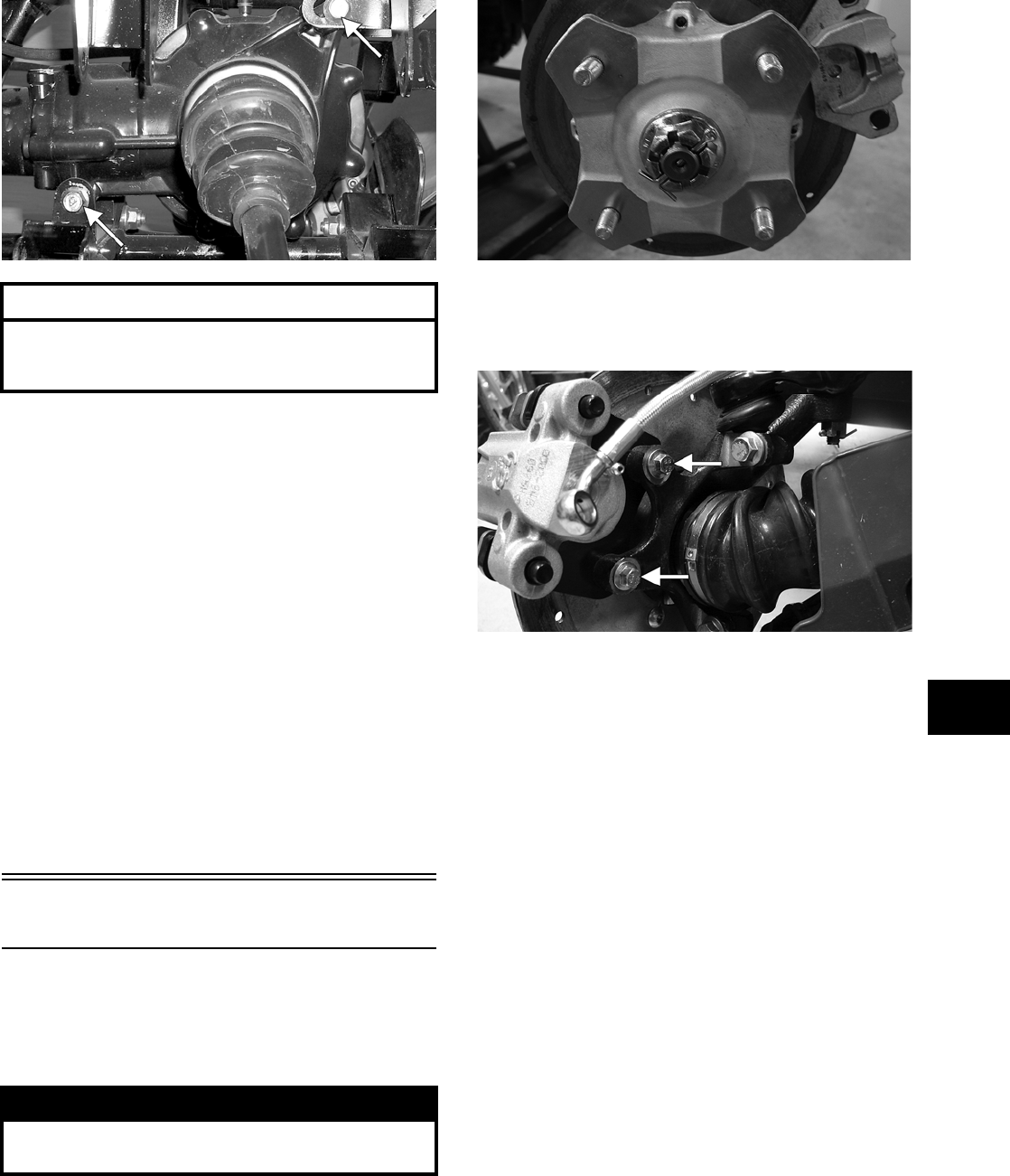
6-23
6
AF960A
INSTALLING
1. Slide the gear case into position through the left
side of the frame; then secure it to the frame
with cap screws and lock nuts. Tighten to speci-
fications.
NOTE: If a new gear case is being installed,
tighten the cap screws to 5.1-6.3 kg-m (37-45.5
ft-lb).
2. Secure the engine output shaft to the rear gear
case input flange with three cap screws (coated
with red Loctite #271) and lock nuts. Tighten to
specifications.
3. Install the rear drive axles (see Drive Axles in
this section).
4. Install the left-side rear A-arms (see Rear
A-Arms in Section 7).
Hub
REMOVING
1. Secure the ATV on a support stand to elevate the
wheel; then remove the wheel.
2. Remove the cotter pin from the nut.
NOTE: During assembly, new cotter pins should
be installed.
KX041
3. Remove the flange nut securing the hub.
4. Remove the brake caliper.
PR243A
5. Remove the hub assembly.
6. Remove the four cap screws securing the brake
disc.
CLEANING AND INSPECTING
NOTE: Whenever a part is worn excessively,
cracked, or damaged in any way, replacement is
necessary.
1. Clean all hub components.
2. Inspect all threads for stripping or damage.
3. Inspect the brake disc for cracks or warping.
4. Inspect the hub for pits, cracks, loose studs, or
spline wear.
INSTALLING
1. Secure the brake disc to the hub with the four
cap screws coated with blue Loctite #243.
Tighten to specifications.
2. Apply grease to the splines in the hub.
AT THIS POINT
For servicing the input shaft, pinion gear, needle
bearing, and axle seal, see Front Differential in this
section.
! WARNING
Make sure the ATV is solidly supported on the sup-
port stand to avoid injury.
FOR ARCTIC CAT ATV DISCOUNT PARTS CALL 606-678-9623 OR 606-561-4983
www.mymowerparts.com
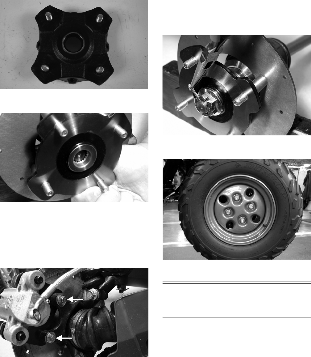
6-24
PR291
3. Install the hub assembly onto the shaft.
CD009
4. Secure the hub assembly with the nut. Tighten
only until snug.
5. Secure the brake caliper to the knuckle with the
two cap screws. Tighten the auxiliary caliper to
specifications. Tighten the hydraulic caliper to
specifications.
PR243A
6. Tighten the hub nut (from step 4) to specifica-
tions; then install and spread a new cotter pin
making sure each side of the pin is flush to the
hub nut.
CD008
7. Install the wheel and tighten to specifications.
CD006
8. Remove the ATV from the support stand.
Hydraulic
Brake Caliper
NOTE: The brake caliper is a non-serviceable
component; it must be replaced as an assembly
(see Section 2).
FOR ARCTIC CAT ATV DISCOUNT PARTS CALL 606-678-9623 OR 606-561-4983
www.mymowerparts.com

7-1
7
SECTION 7 — SUSPENSION
TABLE OF
CONTENTS
Suspension ………..………….…………….…………….….. 7-2
Shock Absorbers ………………….………….……………... 7-2
Front A-Arms ………………….…………….…………….….. 7-3
Rear A-Arms …………………………..…………….……….. 7-5
Wheels and Tires …..…………….…………….…………… 7-7
FOR ARCTIC CAT ATV DISCOUNT PARTS CALL 606-678-9623 OR 606-561-4983
www.mymowerparts.com
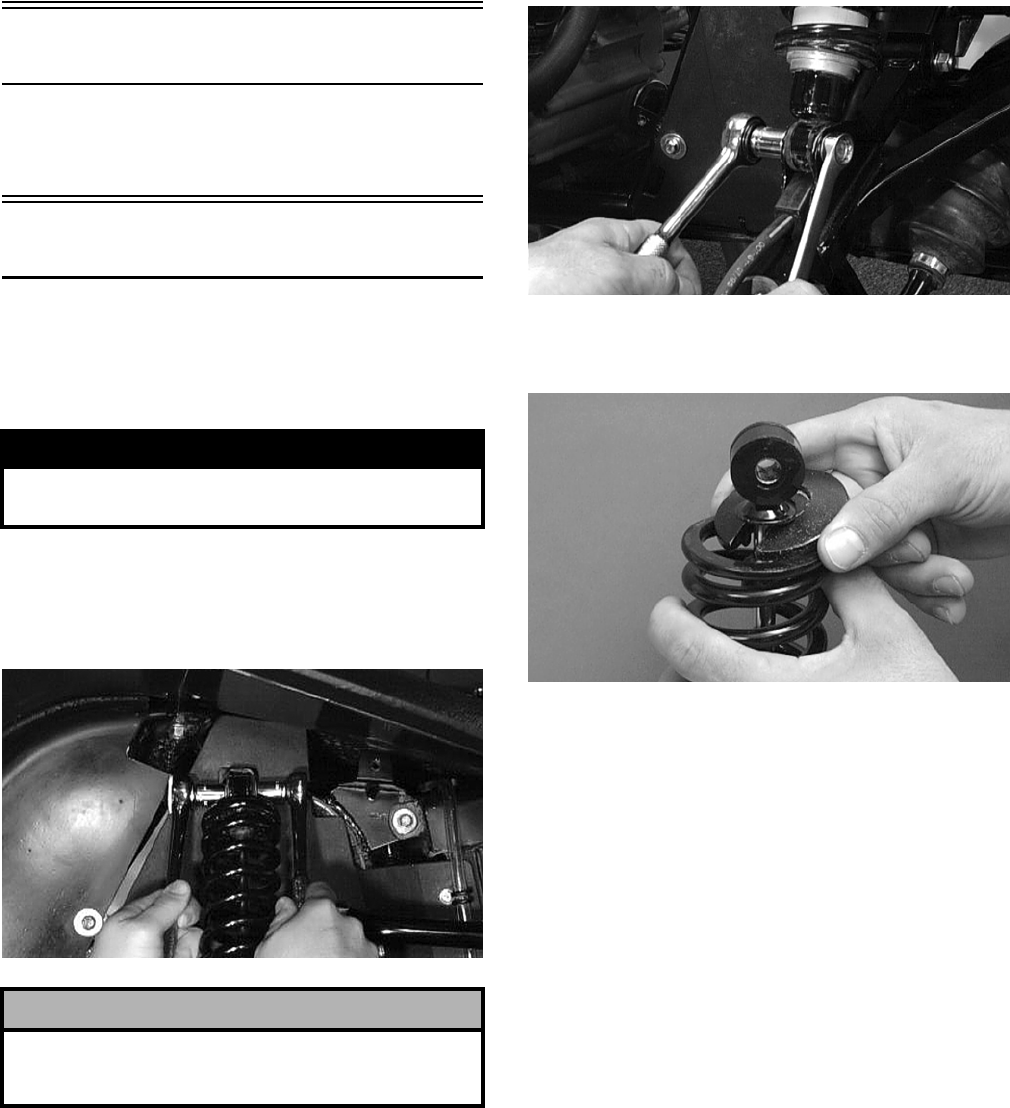
7-2
Suspension
NOTE: Critical torque specifications are located
in Section 10.
Shock Absorbers
REMOVING
1. Secure the ATV on a support stand to elevate the
wheels and to release load on the suspension.
2. Remove the two cap screws and nuts securing
each front shock absorber to the frame and the
upper A-arm. Account for bushings and sleeves
from each.
AF605D
3. Remove the two cap screws and nut securing
each rear shock absorber to the frame and lower
A-arm. Account for bushings and sleeves from
each.
AF626D
4. Compress the shock absorber spring, remove the
retainer, and remove the spring.
AF730D
CLEANING AND INSPECTING
NOTE: Whenever a part is worn excessively,
cracked, or damaged in any way, replacement is
necessary.
1. Clean all shock absorber components in
parts-cleaning solvent.
2. Inspect each shock rod for nicks, pits, rust,
bends, and oily residue.
3. Inspect all springs, spring retainers, shock rods,
sleeves, bushings, shock bodies, and eyelets for
cracks, leaks, and bends.
INSTALLING
1. Place the shock absorber spring over the shock
absorber, compress the spring, and install the
retainer.
! WARNING
Make sure the ATV is solidly supported on the sup-
port stand to avoid injury.
! CAUTION
Additional support stands are necessary to support
the rear axle when the shock absorbers are removed
or damage may occur.
FOR ARCTIC CAT ATV DISCOUNT PARTS CALL 606-678-9623 OR 606-561-4983
www.mymowerparts.com
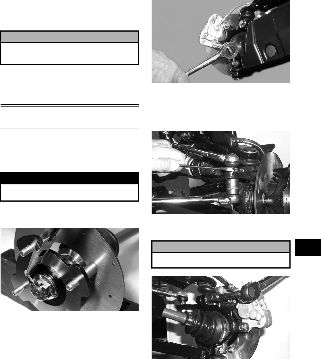
7-3
7
2. Place bushings and sleeves (where appropriate)
into shock eyelet; then install shock with two
cap screws and nuts. Tighten all nuts to specifi-
cations.
NOTE: The rear shock absorber-to-lower A-arm
torque factor is 2.8 kg-m (20 ft-lb).
3. Remove the ATV from the support stand.
Front A-Arms
REMOVING
1. Secure the ATV on a support stand to elevate the
front wheels; then remove the wheels.
2. Remove the cotter pin from the nut. Discard the
cotter pin.
CD008
3. Remove the nut securing the hub.
4. Remove the brake caliper. Account for two cap
screws and two 0.76 mm (0.030 in.) spacer
washers.
CD007
5. Remove the hub assembly.
6. Remove the cotter pin and slotted nut securing
the tie rod end to the knuckle; then remove the
tie rod end from the knuckle.
AF618D
7. Remove the cap screws securing the ball joints
to the knuckle.
AF628D
8. Tap the ball joints out of the knuckle; then
remove the knuckle.
9. Remove the lower shock absorber eyelet from
the upper A-arm.
! CAUTION
Do not tighten the nuts beyond the 4.8 kg-m (35 ft-lb)
specification or the shock eyelet or mount WILL be
damaged.
! WARNING
Make sure the ATV is solidly supported on the sup-
port stand to avoid injury.
! CAUTION
Support the knuckle when removing the cap screws
or damage to the threads will occur.
FOR ARCTIC CAT ATV DISCOUNT PARTS CALL 606-678-9623 OR 606-561-4983
www.mymowerparts.com
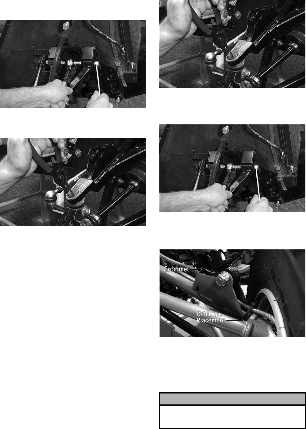
7-4
10. Remove the cap screws securing the A-arms to
the frame.
AF610D
11. Remove the circlip from the ball joint; then
remove the ball joint from the A-arm.
AF616D
CLEANING AND INSPECTING
NOTE: Whenever a part is worn excessively,
cracked, or damaged in any way, replacement is
necessary.
1. Clean all A-arm components in parts-cleaning
solvent.
2. Clean the ball joint mounting hole of all residual
Loctite, grease, oil, or dirt for installing pur-
poses.
3. Inspect the A-arm for bends, cracks, and worn
bushings.
4. Inspect the ball joint mounting holes for cracks
or damage.
5. Inspect the frame mounts for signs of damage,
wear, or weldment damage.
INSTALLING
1. Apply green Loctite #609 to the entire outside
diameter of the ball joint; then install the ball
joint into the A-arm and secure with the circlip.
AF616D
2. Install the A-arm assemblies into the frame
mounts and secure with the cap screws. Only
finger-tighten at this time.
AF610D
3. Route the brake hose through the upper A-arm
shock absorber mount; then secure the hose to
the A-arm with a cable tie and grommet.
DE054A
4. Secure the lower eyelet of the shock absorber to
the upper A-arm. Tighten nut to specifications.
5. Secure the A-arm assemblies to the frame
mounts (from step 2). Tighten the cap screws to
specifications.
! CAUTION
Do not tighten the nut beyond the 4.8 kg-m (35 ft-lb)
specification or the shock eyelet or mount WILL be
damaged.
FOR ARCTIC CAT ATV DISCOUNT PARTS CALL 606-678-9623 OR 606-561-4983
www.mymowerparts.com
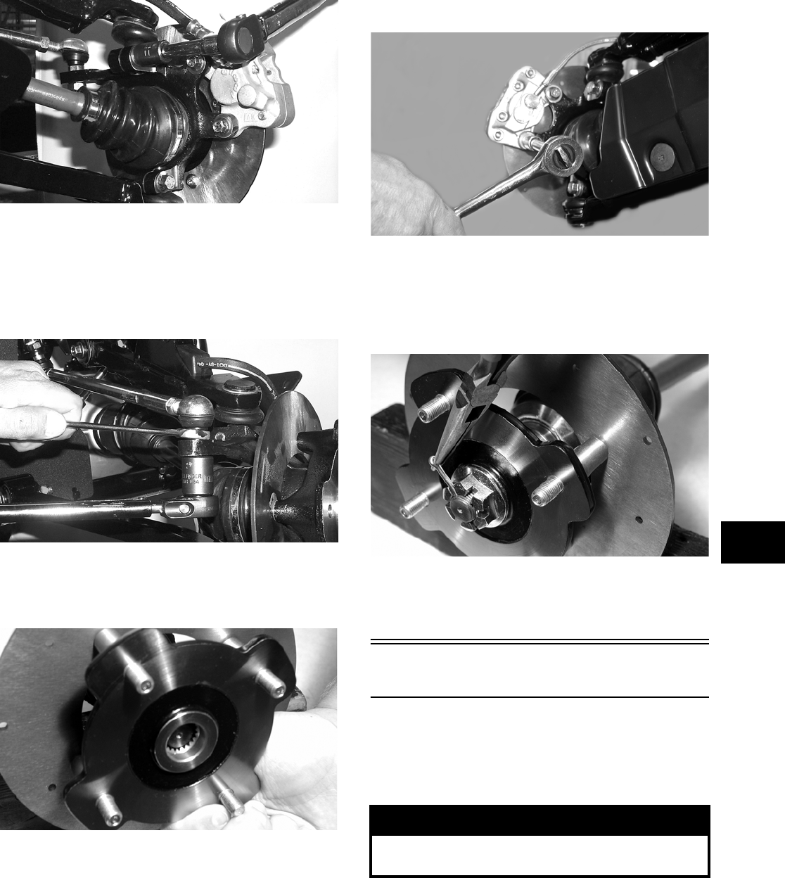
7-5
7
6. Install the knuckle assembly onto the ball joints
and secure with cap screws. Tighten to specifi-
cations.
AF628D
7. Install the tie rod end and secure with the nut.
Tighten to specifications; then install a new cot-
ter pin and spread the pin to secure the nut.
NOTE: During assembly, new cotter pins should
be installed.
AF618D
8. Apply grease to the hub and drive axle splines;
then install the hub assembly onto the drive
axle.
CD009
9. Secure the hub assembly with the nut. Tighten
only until snug.
10. Secure the brake caliper to the knuckle with the
two cap screws making sure the two 0.76 mm
(0.030 in.) spacer washers are positioned
between the caliper and the knuckle. Tighten to
specifications.
CD007
11. Secure the hub nut (from step 9) to the
shaft/axle. Tighten to specifications.
12. Install a new cotter pin and spread the pin to
secure the nut.
CD008
13. Install the wheel and tighten to specifications.
14. Remove the ATV from the support stand.
Rear A-Arms
REMOVING
1. Secure the ATV on a support stand to elevate the
wheels.
2. Pump up the hand brake; then engage the brake
lever lock.
! WARNING
Make sure the ATV is solidly supported on the sup-
port stand to avoid injury.
FOR ARCTIC CAT ATV DISCOUNT PARTS CALL 606-678-9623 OR 606-561-4983
www.mymowerparts.com
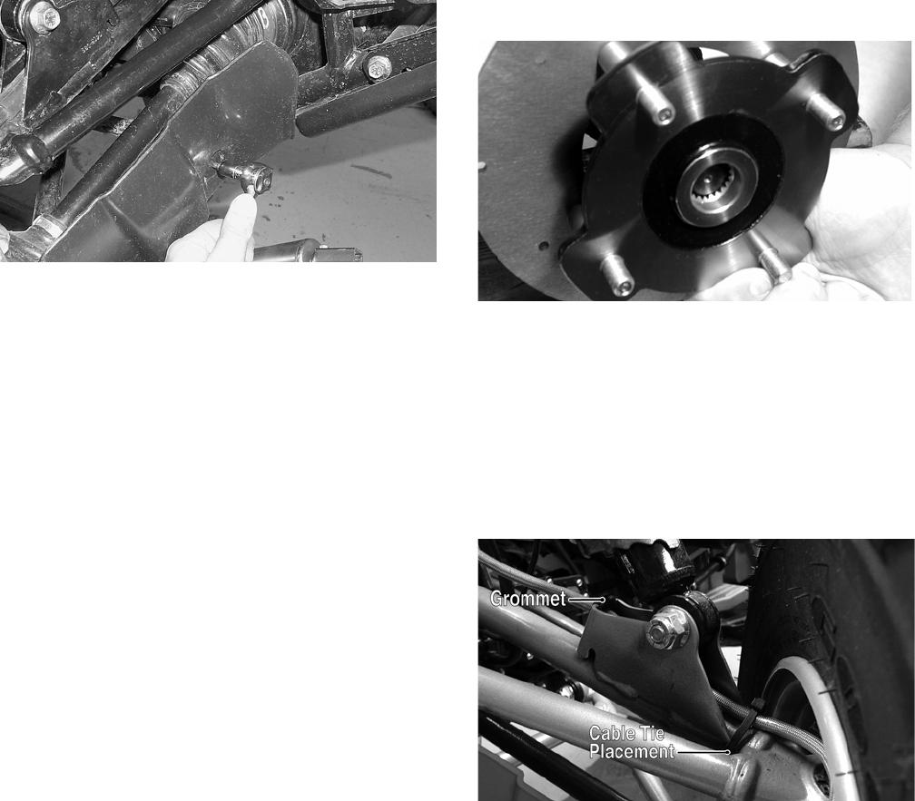
7-6
3. Remove the wheel.
4. Remove the cotter pin securing the hex nut; then
remove the hex nut. Release the brake lever
lock.
5. Remove the caliper (right side only).
NOTE: Do not allow the brake calipers to hang
from their cable/hose.
6. Remove the cap screws and lock nut securing
the shock absorber to the frame and lower
A-arm; then remove the shock absorber.
7. Remove the cap screws securing the boot guard
to the lower A-arm.
AF934
8. Slide the hub out of the knuckle and set aside.
9. Remove the cap screws and lock nuts securing
the knuckle to the A-arms. Discard the lock
nuts.
NOTE: Never reuse a lock nut. Once a lock nut
has been removed, it must be replaced with a new
lock nut.
10. Remove the cap screws and lock nuts securing
the A-arms to the frame; then remove the
A-arms.
NOTE: If removing the upper right A-arm, it will
be necessary to disconnect the brake hose from
the A-arm.
CLEANING AND INSPECTING
NOTE: Whenever a part is worn excessively,
cracked, or damaged in any way, replacement is
necessary.
1. Clean all A-arm components in parts-cleaning
solvent.
2. Inspect the A-arm for bends, cracks, and worn
bushings.
3. Inspect the frame mounts for signs of damage,
wear, or weldment damage.
INSTALLING
1. Install the A-arm assemblies into the frame
mounts and secure with the cap screws and new
lock nuts. Only finger-tighten at this time.
2. Slide the knuckle onto the drive axle and into
position on the A-arms; then secure the knuckle
to the A-arms with cap screws and new lock
nuts. Tighten to specifications.
3. Tighten the hardware securing the A-arms to the
frame mounts (from step 1) to specifications.
4. Apply grease on the drive axle splines; then
install the hub assembly onto the drive axle.
CD009
5. Secure the hub assembly with the nut. Tighten
only until snug.
6. Secure the brake caliper to the knuckle with the
two cap screws (right side only). Tighten the
caliper to specifications.
NOTE: Ensure that the brake hose is properly
routed and secured to the upper A-arm.
DE054A
7. Compress the hand brake lever and engage the
brake lever lock; then secure the hub nut (from
step 5) to the drive axle. Tighten to specifica-
tions.
FOR ARCTIC CAT ATV DISCOUNT PARTS CALL 606-678-9623 OR 606-561-4983
www.mymowerparts.com
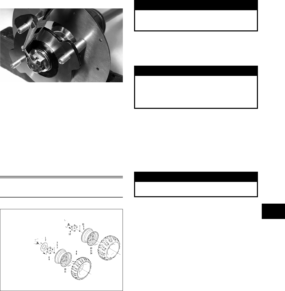
7-7
7
8. Install a new cotter pin and spread the pin to
secure the nut.
CD008
9. Secure the shock absorber to the frame with a
cap screw and new lock nut. Tighten to specifi-
cations.
10. Secure the shock absorber to the lower A-arm
with a cap screw and new lock nut. Tighten to
specifications.
11. Secure the boot guard to the lower A-arm with
the two cap screws. Tighten securely.
12. Install the wheel and tighten to specifications.
13. Remove the ATV from the support stand.
Wheels and Tires
0739-534
TIRE SIZE
The ATV is equipped with low-pressure tubeless
tires of the size and type listed in the General Speci-
fications (see Section 1). Do not under any circum-
stances substitute tires of a different type or size.
TIRE INFLATION PRESSURE
Front and rear tire inflation pressure should be 0.35
kg/cm² (5.0 psi).
REMOVING
1. Secure the ATV on a support stand to elevate the
wheels.
2. Remove the wheels.
NOTE: Keep left-side and right-side wheels sepa-
rated for installing them on their proper sides.
CLEANING AND INSPECTING
NOTE: Whenever a part is worn excessively,
cracked, or damaged in any way, replacement is
necessary.
1. Clean the wheels and hubs with parts-cleaning
solvent.
2. Clean the tires with soap and water.
3. Inspect each wheel for cracks, dents, or bends.
4. Inspect each tire for cuts, wear, missing lugs,
and leaks.
INSTALLING
1. Install each wheel on its hub.
KEY
1. Machine Screw
2. Brake Disc
3. Wheel Hub — Front
4. Hub Stud
5. Cotter Pin
6. Hex Nut
7. Wheel
8. Mounting Nut
9. Tire — Front
10. Valve Stem
11. Valve Stem Cap
12. Wheel Hub — Rear
13. Wheel
14. Tire — Rear
! WARNING
Use only Arctic Cat approved tires when replacing
tires. Failure to do so could result in unstable ATV
operation.
! WARNING
Do not mix tire tread patterns. Use the same pattern
type on front and rear. Failure to heed warning could
cause poor handling qualities of the ATV and could
cause excessive drive train damage not covered by
warranty.
! WARNING
Make sure the ATV is solidly supported on the sup-
port stand to avoid injury.
FOR ARCTIC CAT ATV DISCOUNT PARTS CALL 606-678-9623 OR 606-561-4983
www.mymowerparts.com
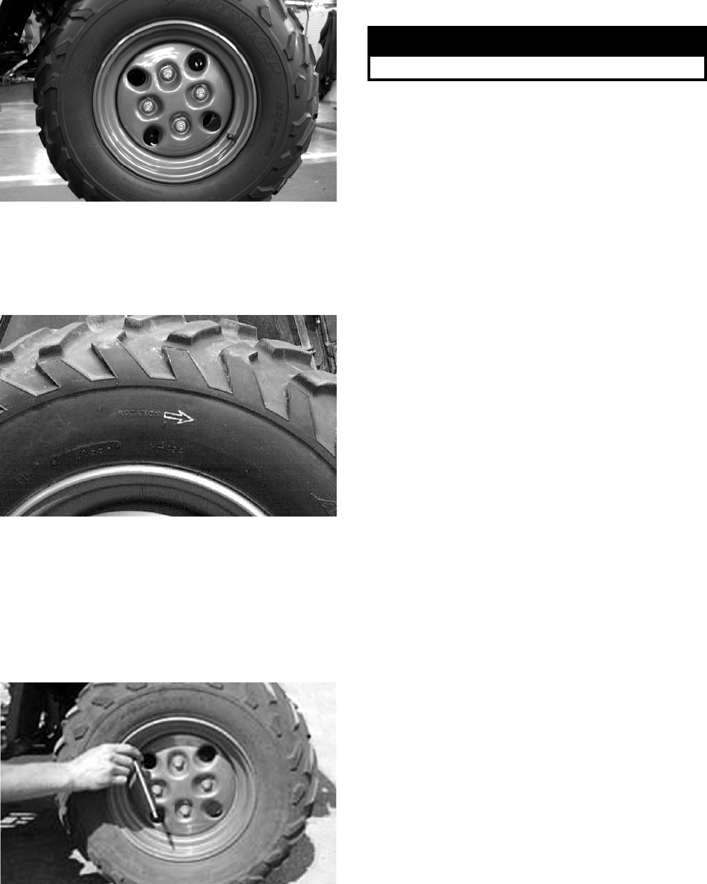
7-8
CD006
NOTE: Make sure each wheel is installed on its
proper hub as noted in removing (the “rotation
arrow” (if applicable) must indicate forward direc-
tion of rotation).
AF612D
2. Tighten to specifications.
CHECKING/INFLATING
1. Using an air pressure gauge, measure the air
pressure in each tire. Adjust the air pressure as
necessary to meet the recommended inflation
pressure.
CD005
2. Inspect the tires for damage, wear, or punctures.
NOTE: If repair is needed, follow the instructions
found on the tire repair kit or remove the wheel and
have it repaired professionally.
NOTE: Be sure all tires are the specified size and
have identical tread pattern.
3. Check the front wheel toe-in and toe-out and
adjust as necessary (see Section 8).
4. Test drive the ATV on a dry, level surface and
note any pulling to the left or right during accel-
eration, deceleration, and braking.
NOTE: If pulling is noted, measure the circumfer-
ence of the front and rear tires on the pulling side.
Compare the measurements with the tires on the
opposite side. If pulling is noted during braking
only, check and adjust the brakes as necessary
and recheck operation (see Section 2).
5. Increase the air pressure in the tires with the
smallest circumference measurement until all
tires are equal in circumference.
6. Repeat steps 4-5 as necessary to ensure proper
handling.
! WARNING
Do not operate the ATV if tire damage exists.
FOR ARCTIC CAT ATV DISCOUNT PARTS CALL 606-678-9623 OR 606-561-4983
www.mymowerparts.com

8-1
8
SECTION 8 — STEERING/FRAME
TABLE OF
CONTENTS
Steering/Frame………………………..…………….……….. 8-2
Steering Post/Tie Rods ………………….………….…….. 8-2
Handlebar Grip……………….………….…………….…….. 8-5
Steering Knuckles …………..…………….…………….….. 8-6
Measuring/Adjusting Toe-In……….…………….……….. 8-8
Front Rack ……….………….…………….…………….…….. 8-9
Front Bumper Assembly ………..…………….…………. 8-10
Front/Rear Body Panel …….…………….………….…… 8-10
Front Body Panel/Side Panels
(TBX/TRV/500/650 H1/700 EFI) …………………… 8-13
Footrests …..…………….……………..……………………. 8-17
Belly Panel ……………………………..……………………. 8-18
Exhaust System ……………..…………….…………….… 8-18
Rear Body Panel/Rack ………….…………….…………. 8-19
Side Storage Box (TBX Models) ……………………… 8-20
Cargo Box (TBX Models) …………….………….……… 8-21
Adjusting Headlight ……………………….…………….… 8-22
Taillight Assembly..……………….………………..……… 8-22
Seat……………..…………….………….…………….……… 8-22
FOR ARCTIC CAT ATV DISCOUNT PARTS CALL 606-678-9623 OR 606-561-4983
www.mymowerparts.com
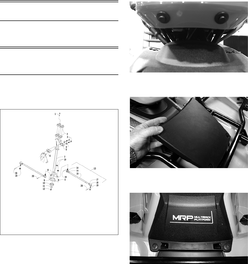
8-2
Steering/Frame
NOTE: Critical torque specifications are located
in Section 10.
Steering Post/
Tie Rods
NOTE: Some components may vary from model
to model. The technician should use discretion
and sound judgment.
0739-774
REMOVING
1. Remove the ignition switch retaining ring; then
remove the reinstallable rivets securing the
instrument pod to the mounting bracket and
remove the pod.
CD759
2. Remove the reinstallable rivets securing the
radiator access cover and remove the cover.
CD666
3. Remove four reinstallable rivets securing the
steering post cover and remove the cover.
CD667
4. Unlatch the storage compartment lid; then slide
the storage compartment cover assembly for-
ward and lift off.
KEY
1. Cap Screw
2. Cap
3. Shoulder Screw
4. Housing Cap
5. Housing
(Lower)
6. Housing
(Upper)
7. Steering Post
8. Cap Screw
9. Bearing Flange
10. Bearing w/Oil
Seal
11. Washer
12. Cap Screw
13. Tie Rod Assy
14. Ball Joint (Left)
15. Nut (Left)
16. Tie Rod
17. Nut (Right)
18. Ball Joint
(Right)
19. Lock Nut
20. Cotter Pin
FOR ARCTIC CAT ATV DISCOUNT PARTS CALL 606-678-9623 OR 606-561-4983
www.mymowerparts.com
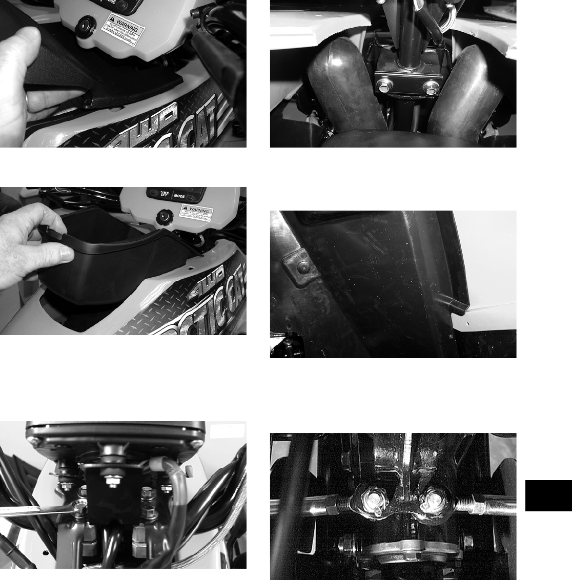
8-3
8
CD669
5. Remove the storage compartment.
CD671
6. Remove the four cap screws securing the han-
dlebar caps and speedometer bracket to the
steering post; then move the handlebar and
speedometer out of the way. Account for four
handlebar caps.
CD762
7. Remove two cap screws securing the upper
steering post bearing to the frame. Account for
two bearings and two housings.
CD760
8. Using a suitable lift stand, raise the ATV enough
to remove the front wheels; then remove the
left-side and right-side splash panels.
CD685
9. Remove the cotter pins and slotted nuts from the
inner and outer tie rod ends; then remove the tie
rods from the steering post arm and the left-side
and right-side steering knuckles.
AF778D
FOR ARCTIC CAT ATV DISCOUNT PARTS CALL 606-678-9623 OR 606-561-4983
www.mymowerparts.com
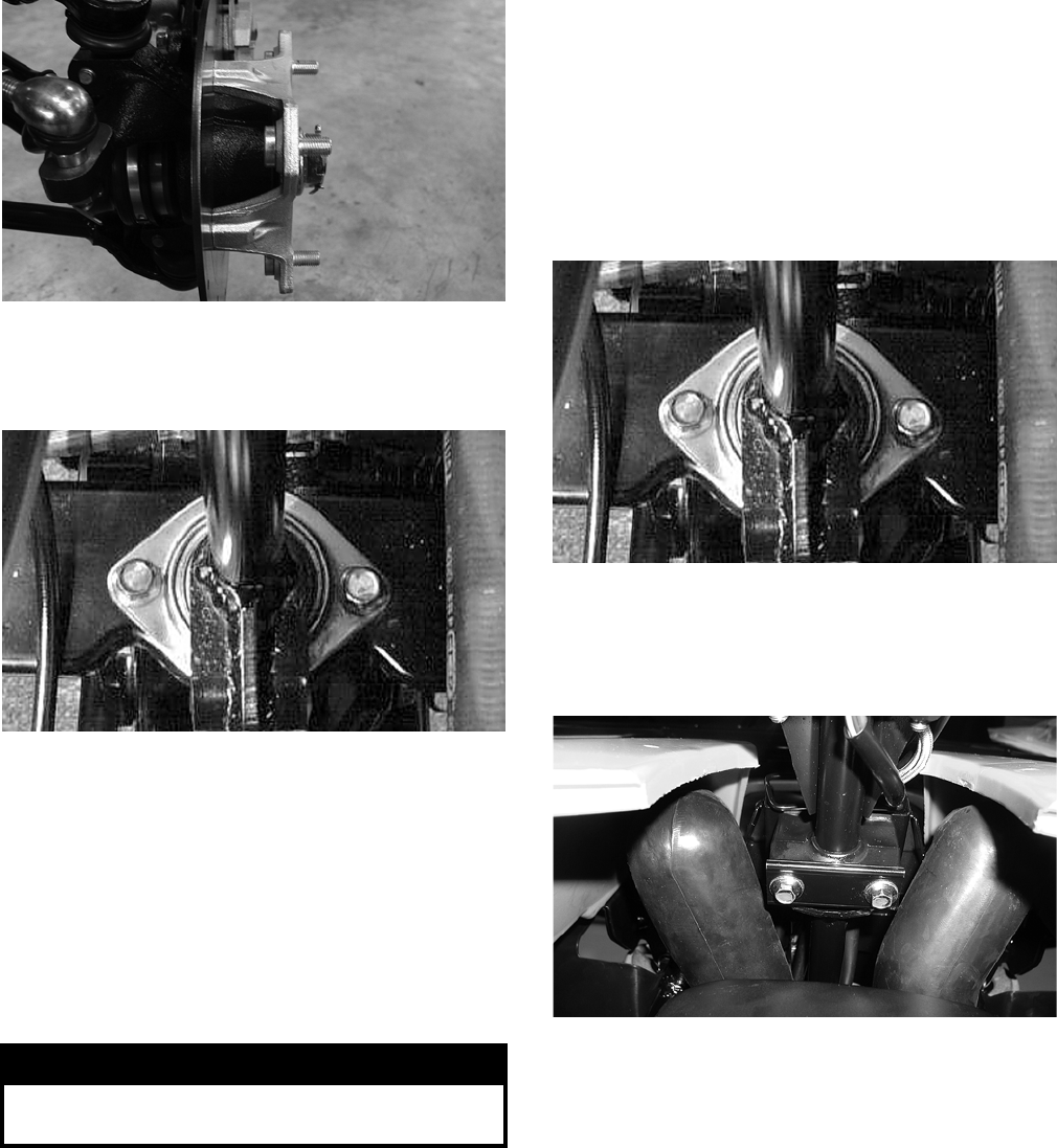
8-4
KX039
10. Remove two cap screws securing the lower
steering post bearing flange to the frame; then
remove the steering post.
AL600D
CLEANING AND INSPECTING
NOTE: Whenever a part is worn excessively,
cracked, or damaged in any way, replacement is
necessary.
1. Wash the tie rod ends in parts-cleaning solvent.
Dry with compressed air. Inspect the pivot area
for wear. Apply a low-temperature grease to the
ends.
2. Inspect the tie rods for damaged threads or wear.
3. Inspect the tie rods for cracks or unusual bends.
4. Inspect all welded areas for cracks or deteriora-
tion.
5. Inspect the steering post and steering-post
brackets for cracks, bends, or wear.
6. Inspect the bearing halves, bearing caps, and
bearing housings for cracks or wear.
7. Inspect the handlebar tube for cracks, wear, or
unusual bends.
8. Inspect the handlebar grips for damage or wear.
INSTALLING
1. Place the steering post into position; then secure
the lower bearing flange to the frame with two
cap screws. Tighten to specifications.
AL600D
2. Place the upper steering post bearings into the
housings; then position on the steering post and
secure the housings to the frame with two cap
screws. Tighten to specifications.
CD760
3. Install the tie rods and secure with the slotted
nuts. Tighten to specifications; then install new
cotter pins.
NOTE: If the slots do not align with the holes in
the tie rod ends, tighten the nuts just enough to
allow installation of the cotter pins.
! WARNING
Always wear safety glasses when using compressed
air.
FOR ARCTIC CAT ATV DISCOUNT PARTS CALL 606-678-9623 OR 606-561-4983
www.mymowerparts.com
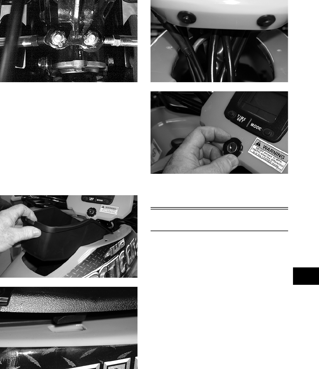
8-5
8
AF778D
4. Install the splash panels; then install the front
wheels and tighten to specifications using a
crisscross pattern.
5. Lower the ATV and place the handlebar and
caps into position on the steering post; then
position the speedometer on top of the caps and
secure with the four cap screws. Tighten to spec-
ifications.
6. Install the storage compartment box; then attach
the storage compartment cover assembly by
engaging the lugs into the slots and sliding rear-
ward. Lock the storage compartment lid to hold
the assembly in place.
CD671
CD670
7. Place the instrument pod into position over the
speedometer; then secure with two reinstallable
rivets and the ignition switch locking ring.
CD677
CD676
8. Install the steering post access cover and secure
with four reinstallable rivets; then install and
secure the radiator access cover.
Handlebar Grip
REMOVING
1. Remove the plug from the head of the rivet.
2. Using a 1/8-in. drill bit, drill out the rivet.
3. Using compressed air between the grip and the
handlebar, twist the grip back and forth until it
slides free of the handlebar.
INSPECTING
NOTE: Whenever a part is worn excessively,
cracked, or damaged in any way, replacement is
necessary.
1. Inspect the grip for wear, cuts, or cracks.
2. Inspect the grip for deterioration.
FOR ARCTIC CAT ATV DISCOUNT PARTS CALL 606-678-9623 OR 606-561-4983
www.mymowerparts.com
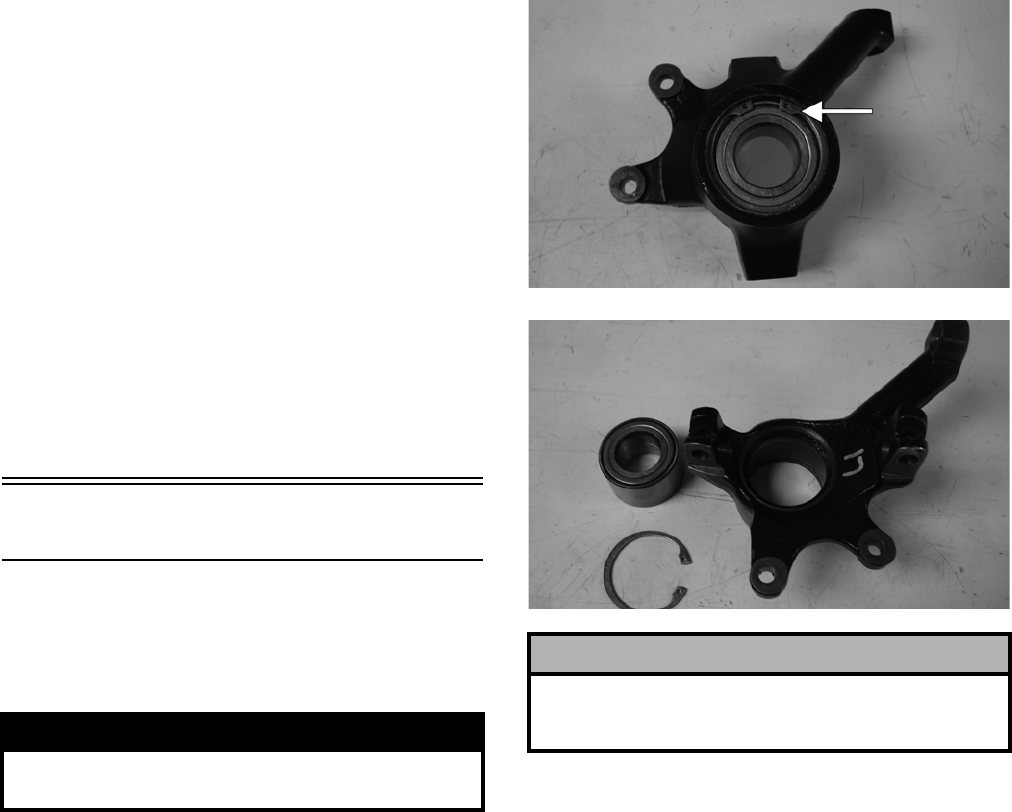
8-6
INSTALLING
NOTE: Before installing a grip, use contact spray
or alcohol to clean the inside of the grip and the
handlebar of glue residue, oil, or any other con-
taminant.
1. Apply a liberal amount of Handlebar Grip
Adhesive to the inside of the grip.
2. Align the rivet hole in the grip with the rivet
hole in the handlebar; then align the notch
(inside the grip) with the slot in the handlebar
and slide the grip onto the handlebar until it is
fully seated.
3. Wipe off any excess glue; then secure the grip
with a new rivet.
4. Install the plug on the head of the rivet.
Steering Knuckles
REMOVING AND DISASSEMBLING
1. Secure the ATV on a support stand to elevate the
wheel; then remove the wheel.
2. Remove the wheel cap from the hub; then
remove the cotter pin from the nut.
3. Remove the nut securing the hub.
4. Remove the brake caliper.
5. Remove the hub assembly.
6. Remove the cotter pin from the tie rod end and
remove the tie rod end from the knuckle.
7. Remove the two cap screws securing the ball
joints in the knuckle.
8. Tap the ball joint end out of the knuckle; then
remove the knuckle.
9. Remove the snap ring from the knuckle; then
remove the bearing.
PR287A
PR288
CLEANING AND INSPECTING
NOTE: Whenever a part is worn excessively,
cracked, or damaged in any way, replacement is
necessary.
1. Clean all knuckle components.
2. Inspect the bearing for pits, gouges, rusting, or
premature wear.
3. Inspect the knuckle for cracks, breaks, or poros-
ity.
4. Inspect threads for stripping or damage.
! WARNING
Make sure the ATV is solidly supported on the sup-
port stand to avoid injury.
! CAUTION
Use extreme care when removing the bearing. If the
bearing is allowed to fall, it will be damaged and will
have to be replaced.
FOR ARCTIC CAT ATV DISCOUNT PARTS CALL 606-678-9623 OR 606-561-4983
www.mymowerparts.com
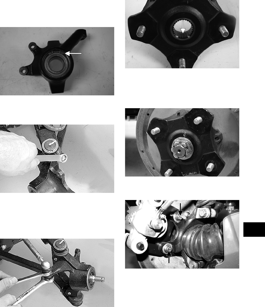
8-7
8
ASSEMBLING AND INSTALLING
1. Install the bearing; then install the snap ring
making sure it seats into the knuckle.
PR287A
2. Install the knuckle to the upper and lower ball
joints and secure with the two cap screws.
Tighten to specifications.
AF760D
3. Install the tie rod end and secure with the nut.
Tighten to specifications; then install a new cot-
ter pin and spread the pin.
NOTE: During assembling, new cotter pins
should be installed.
AF759D
4. Apply a small amount of grease to the hub
splines.
PR290A
5. Install the hub assembly onto the splines of the
shaft.
6. Secure the hub assembly with the nut. Tighten
only until snug.
PR257
7. Secure the brake caliper to the knuckle with the
two cap screws. Tighten to specifications.
PR264A
8. Pump the hand brake lever; then engage the
brake lever lock.
9. Secure the hub nut (from step 6) to the shaft.
Tighten to specifications.
10. Install a new cotter pin and spread the pin to
secure the nut.
11. Install the wheel; then using a crisscross pattern,
tighten to specifications.
FOR ARCTIC CAT ATV DISCOUNT PARTS CALL 606-678-9623 OR 606-561-4983
www.mymowerparts.com
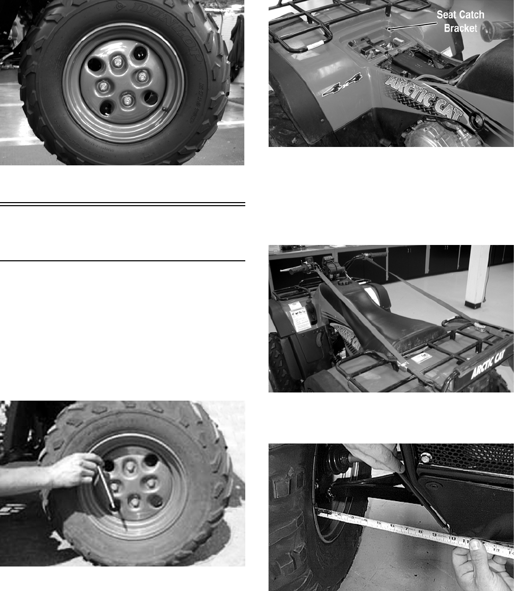
8-8
CD006
12. Remove the ATV from the support stand.
Measuring/Adjusting
Toe-In
1. Thoroughly wash the ATV to remove excess
weight (mud, etc.).
2. Refer to the specifications and ensure the tires
are properly inflated to the recommended pres-
sure.
NOTE: Ensure the inflation pressure is correct in
the tires or inaccurate measurements can occur.
CD005
3. Place the ATV in a level position taking care not
to push down or lift up on the front end; then
turn the handlebar to the straight ahead position.
NOTE: When measuring and adjusting, there
should be a normal operating load on the ATV
(without an operator but with Arctic Cat approved
accessories).
4. Measure the distance from the outside edge of
each handlebar grip to the seat catch brackets.
CD012A
5. Adjust the handlebar direction until the two
measurements are equal; then secure the handle-
bar to the rear rack using tie-down straps.
NOTE: Care must be taken not to allow the han-
dlebar to turn while securing it.
CD014
6. Measure the distance from the inside of each
front rim to the lower frame tube.
AF785D
FOR ARCTIC CAT ATV DISCOUNT PARTS CALL 606-678-9623 OR 606-561-4983
www.mymowerparts.com
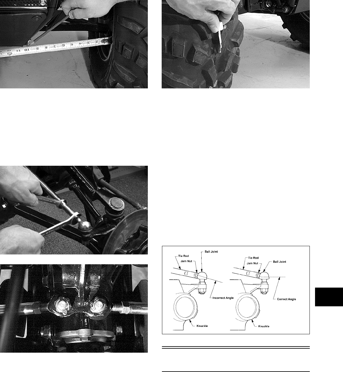
8-9
8
AF786D
NOTE: The distances from the inside rims to the
frame tubes should be equal. If the measurements
are equal, proceed to step 8; if the measurements
are not equal, proceed to step 7.
7. To make the measurements equal, loosen the
appropriate tie rod jam nuts and adjust accord-
ingly; then proceed to step 8.
AF617D
AF778D
NOTE: The front wheels do not have to be
removed to adjust the tie rod. Also, care should be
taken not to disturb the handlebar position.
8. Using a permanent marker of some type, mark
the center of each front tire (at a height parallel
to the belly panel).
AF789D
9. Measure the distance between the marks (at a
height parallel to the belly panel) at the front
side; then record the measurement.
10. Push the ATV forward until the marks are paral-
lel to the belly panel on the back side; then mea-
sure the distance between the marks.
11. The difference in the measurements must show
3.2-6.4 mm (1/8-1/4 in.) toe-in (the front mea-
surement 3.2-6.4 mm (1/8-1/4 in.) less than the
rear measurement).
12. If the difference in the measurements is not
within specifications, adjust both tie rods
equally until within specifications.
NOTE: Prior to locking the jam nuts, make sure
the ball joints are at the center of their normal
range of motion and at the correct angle.
733-559A
Front Rack
REMOVING
1. Remove the two cap screws and lock nuts secur-
ing the front fender panel.
2. Remove the cap screws and lock nuts securing
the rack to the frame.
FOR ARCTIC CAT ATV DISCOUNT PARTS CALL 606-678-9623 OR 606-561-4983
www.mymowerparts.com
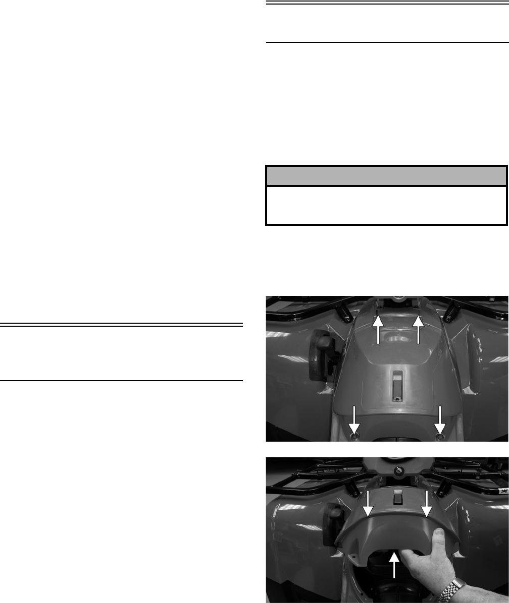
8-10
3. Remove the front rack from the ATV.
CLEANING AND INSPECTING
NOTE: Whenever a part is worn excessively,
cracked, or damaged in any way, replacement is
necessary.
1. Clean all rack components with parts-cleaning
solvent.
2. Inspect all welds for cracking or bending.
3. Inspect threaded areas of all mounting bosses
for stripping.
4. Inspect for missing decals and/or reflectors.
INSTALLING
1. Place the rack into position on the frame and
front fender panel. Install the cap screws and
lock nuts and finger-tighten only.
2. Install the two cap screws and lock nuts securing
the rack to the fenders. Tighten all hardware
securely.
Front Bumper
Assembly
REMOVING
1. Remove the two flange bolts and lock nuts secur-
ing the upper bumper supports to the bumper.
2. Remove the through-bolt and lock nut securing
the bumper to the frame; then remove the
bumper.
CLEANING AND INSPECTING
NOTE: Whenever a part is worn excessively,
cracked, or damaged in any way, replacement is
necessary.
1. Clean all bumper components with parts-clean-
ing solvent.
2. Inspect all welds for cracking or bending.
INSTALLING
1. Place the front bumper assembly into position
and install the through-bolt. Start the lock nut
and finger-tighten only.
2. Install the two flange bolts and lock nuts on the
upper supports. Tighten all hardware securely.
Front/Rear Body Panel
REMOVING
1. Remove the seat; then remove the battery
cover/tool tray.
2. Remove the negative battery cable from the bat-
tery; then remove the positive cable. Remove
the vent hose; then remove the battery.
3. Remove four reinstallable rivets securing the
storage compartment to the body; then remove
the storage compartment and the steering post
cover.
CF145A
CF143A
4. Remove the left-side and right-side fender
splash panels; then remove one press-in fastener
and one reinstallable rivet from the left side and
right side of the air-intake splash shroud. Do not
remove the shroud.
5. Disconnect the four headlight connectors and
the taillight/brakelight connector from the sock-
ets.
! CAUTION
Battery acid is harmful if it contacts eyes, skin, or
clothing. Care must be taken whenever handling a
battery.
FOR ARCTIC CAT ATV DISCOUNT PARTS CALL 606-678-9623 OR 606-561-4983
www.mymowerparts.com
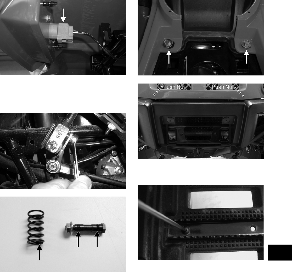
8-11
8
CF135A
6. Remove the shift knob; then remove the nut and
axle pivot bolt securing the lever to the shift
lever axle. Remove the shift lever. Account for
the two O-rings on the axle bolt and one spring.
CD779
CD780A
7. Remove the front and rear racks; then remove
the two body bolts adjacent to the air filter hous-
ing and two push nuts located behind the grille.
CF201A
CF160A
8. Remove the two cap screws and lock nuts secur-
ing the left foot peg and remove the foot peg.
CD782
9. Remove eight cap screws and lock nuts and one
reinstallable rivet securing the right-side foot-
well to the fenders.
10. Lift and support the rear of the body to allow
access to the torx-head cap screws securing the
front and rear body sections together; then
remove six self-locking nuts (three from each
side). Remove the rear body panel; then remove
the front one.
FOR ARCTIC CAT ATV DISCOUNT PARTS CALL 606-678-9623 OR 606-561-4983
www.mymowerparts.com
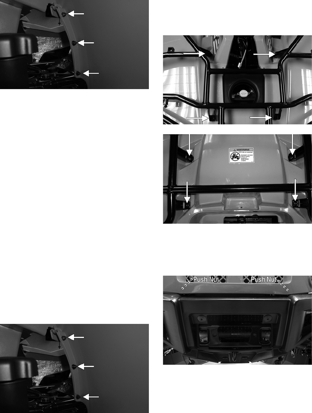
8-12
CF213A
NOTE: To aid in removing the body without sepa-
rating the front and rear panels, it is advisable to
have an assistant help with lifting and guiding the
body clear of the handlebar.
CLEANING AND INSPECTING
NOTE: Whenever a part is worn excessively,
cracked, or damaged in any way, replacement is
necessary.
1. Clean all fender components with part-cleaning
solvent and soap and water.
2. Inspect fenders for cracks and/or loose rivets.
3. Inspect for any missing decals.
INSTALLING
1. Place the body assembly into position on the
ATV.
NOTE: If the front and rear body panels have
been separated, proceed to step 2; if the panels
have not been separated, proceed to step 3.
2. Install the torx-head cap screws and lock nuts
securing the front and rear body panels together.
Tighten securely.
CF213A
3. Making sure the body mounting grommets are
in place, position the front and rear racks; then
install the eight flanged cap screws and lock
nuts. Do not tighten at this time.
CD679A
CD690A
4. Install four rack-to-body machine screws and
lock nuts on the front and rear racks, two push
nuts behind the grille, and two body bolts adja-
cent the air filter housing; then tighten all fasten-
ers (from step 3 and 4) securely.
CF160A
FOR ARCTIC CAT ATV DISCOUNT PARTS CALL 606-678-9623 OR 606-561-4983
www.mymowerparts.com
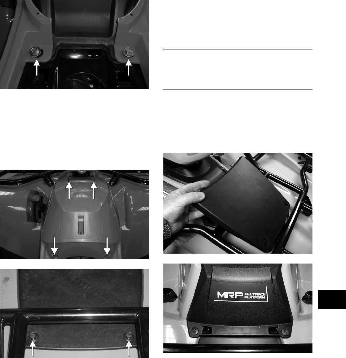
8-13
8
CF201A
5. Install eight cap screws and lock nuts securing
the right-side footwell to the front and rear fend-
ers; then place the left-side foot peg into posi-
tion and secure with two cap screws and lock
nuts. Tighten securely.
6. Place the storage compartment into position;
then install the steering post cover. Secure with
the reinstallable rivets.
CF145A
CF134A
7. Place the shift lever into position making sure
the spring is installed; then secure with the axle
pivot bolt and lock nut.
8. Install the shift knob and the left-side and
right-side splash panels; then reconnect the
headlights. Tighten all fasteners securely.
9. Place the battery into position in the battery box;
then connect the vent hose.
10. Connect the positive battery cable; then connect
the negative battery cable. Tighten the battery
terminal cap screws securely.
11. Install the battery cover/tool tray; then install the
seat. Make sure the seat locks securely.
Front Body Panel/
Side Panels
(TBX/TRV/500/650 H1/700 EFI)
REMOVING
1. Remove the reinstallable rivets securing the
radiator access cover and remove the cover; then
remove four reinstallable rivets securing the
steering post cover and remove the cover.
CD666
CD667
2. Unlock the storage compartment lid; then slide
the storage compartment cover assembly for-
ward and lift off the storage compartment.
FOR ARCTIC CAT ATV DISCOUNT PARTS CALL 606-678-9623 OR 606-561-4983
www.mymowerparts.com
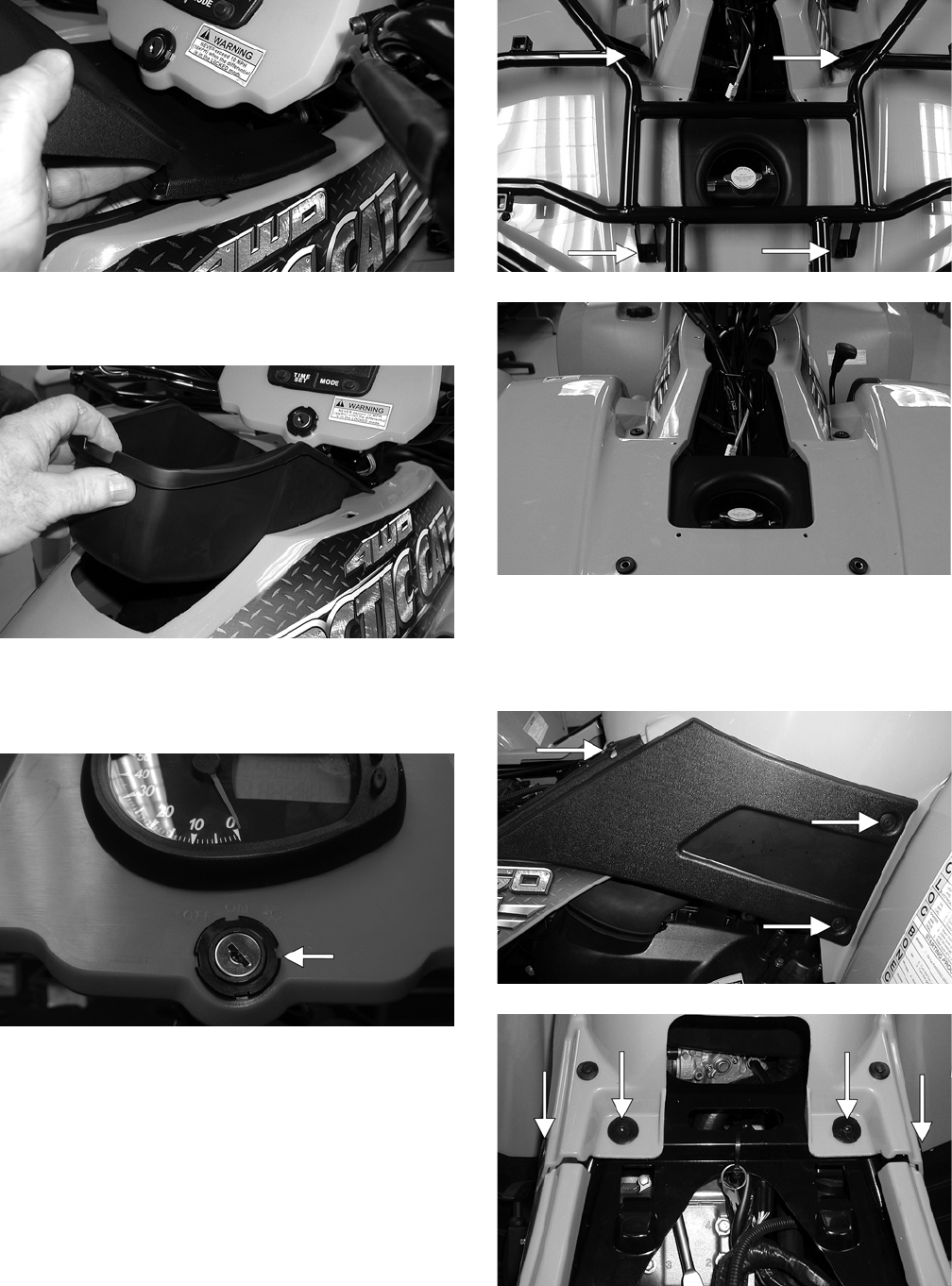
8-14
CD669
3. Remove the storage compartment box; then
remove the seat.
CD671
4. Remove the ignition switch lock collar and two
reinstallable rivets securing the instrument pod;
then remove the instrument pod.
CF207A
5. Remove four machine screws and lock nuts
securing the front rack to the frame; then
remove the front rack. Account for four grom-
mets and four bushings.
CD679A
CD680
6. Remove three reinstallable rivets securing the
right side panel; then remove two torx-head cap
screws securing the rear of the front panel to the
frame.
CD683A
CD684A
FOR ARCTIC CAT ATV DISCOUNT PARTS CALL 606-678-9623 OR 606-561-4983
www.mymowerparts.com
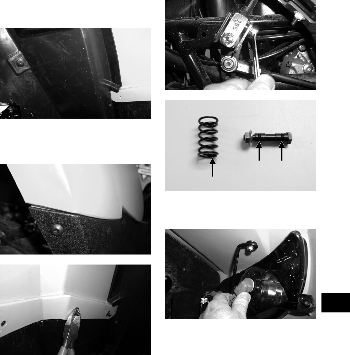
8-15
8
7. Remove the torx-head cap screws and nylon ties
securing the left-side and right-side splash pan-
els; then remove the panels.
CD685
8. Remove one shoulder screw and four plastic riv-
ets on each side to separate the front panel lower
fenders from the left-side and right-side foot-
wells.
CD691
CD682
9. Remove the shift knob retaining pin and remove
the shift knob; then remove the shift lever pivot
axle nut and remove the axle and shift lever.
Account for a spring and two O-rings.
CD779
CD780A
10. Disconnect four headlight connectors and secure
the wires out of the way; then disconnect the
wires to the front accessory plug.
CD681
11. Rotate the handlebar to the full-left position;
then lift and slide the panel to the rear and lift
the rear up to clear the handlebar.
FOR ARCTIC CAT ATV DISCOUNT PARTS CALL 606-678-9623 OR 606-561-4983
www.mymowerparts.com
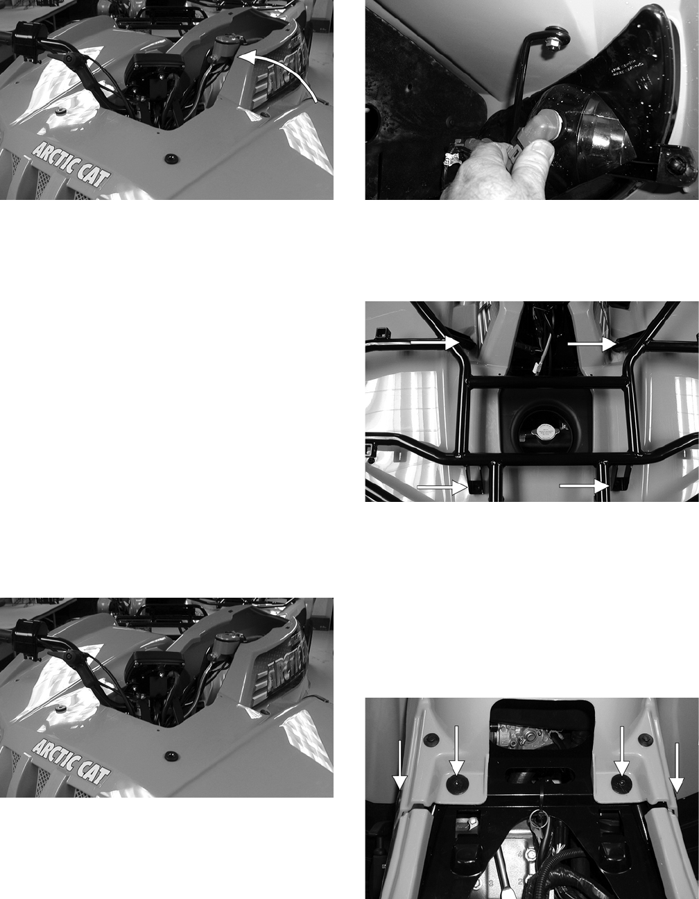
8-16
CD765A
NOTE: It may be necessary to rotate the body
panel to the right to align the opening with the han-
dlebar.
CLEANING AND INSPECTING
NOTE: Whenever a part is worn excessively,
cracked, or damaged in any way, replacement is
necessary.
1. Clean all fender components with part-cleaning
solvent and soap and water.
2. Inspect fenders for cracks and/or loose rivets.
3. Inspect for any missing decals.
INSTALLING
1. Rotate the handlebar to the full-left position;
then place the front body panel over the handle-
bar and rotate and lower into position.
CD765
2. Connect the headlight connectors to the appro-
priate headlights and the front accessory plug
wires to the accessory plug.
CD681
3. Make sure the four rubber grommets and bush—
ings are in place; then place the front rack into
position and secure with four machine screws
and flange nuts. Tighten securely.
CD679A
4. Install one machine screw and flange nut and
four plastic rivets on each side to secure the
front fenders to the footwells. Tighten the flange
nuts securely.
NOTE: If the footwells have been removed, see
Footrests in this section.
5. Install four cap screws securing the front body
panel to the frame and rear panel.
CD684A
6. Install the shift lever spring, shift lever, and
pivot axle; then tighten the axle nut securely.
FOR ARCTIC CAT ATV DISCOUNT PARTS CALL 606-678-9623 OR 606-561-4983
www.mymowerparts.com
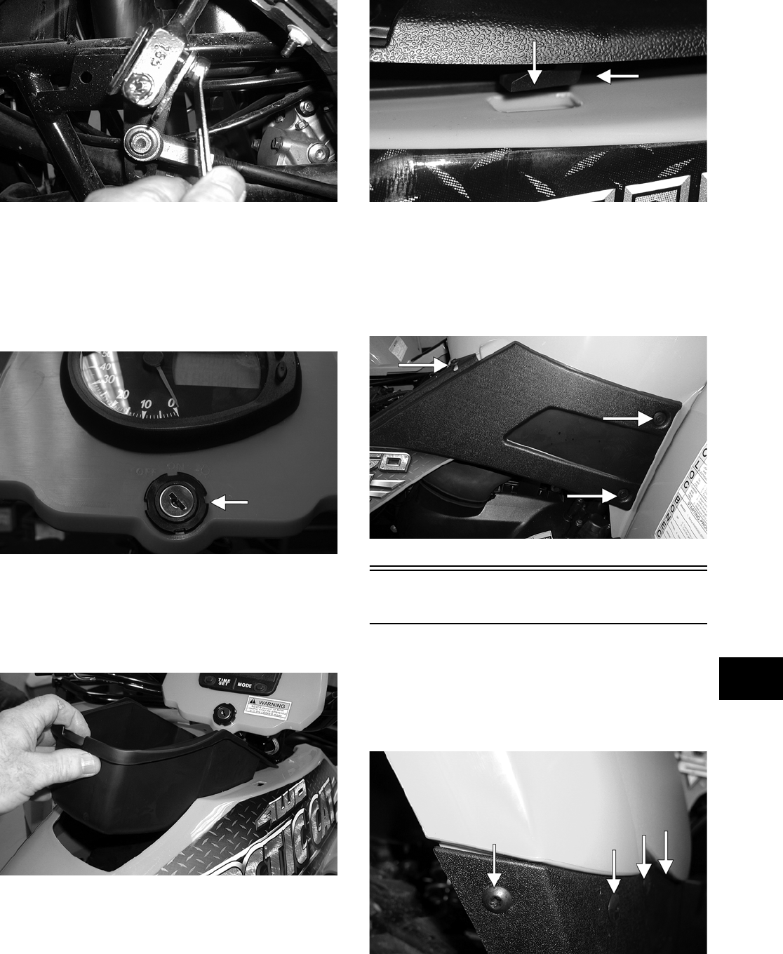
8-17
8
CD779
7. Install the left-side and right-side splash panels
and tighten the cap screws securely. Install new
nylon ties in the appropriate locations.
8. Install the instrument pod and ignition switch;
then secure with two reinstallable rivets and the
ignition switch lock collar.
CF207A
9. Set the storage compartment box into position;
then install the storage compartment cover mak-
ing sure the mounting lugs engage the slots.
Slide rearward to secure and lock by engaging
the lid lock.
CD671
CD670A
10. Install the steering post cover and secure with
the reinstallable rivets; then install and secure
the radiator access panel.
11. Install the left and right side panels and secure
with reinstallable rivets.
CD683A
Footrests
REMOVING
1. Remove the machine screws and flange nuts
securing the front and rear fenders to the foot-
wells.
CD691A
FOR ARCTIC CAT ATV DISCOUNT PARTS CALL 606-678-9623 OR 606-561-4983
www.mymowerparts.com
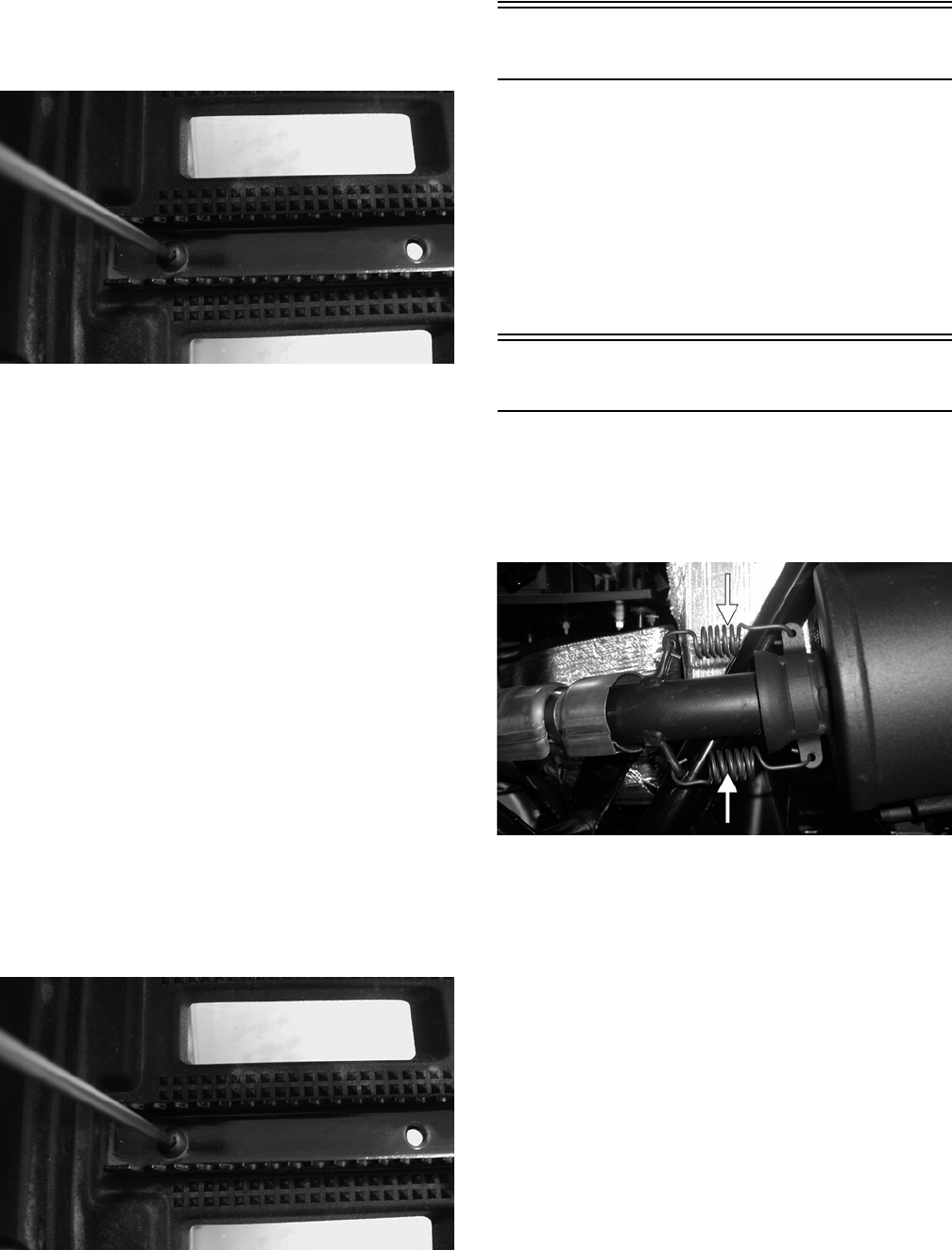
8-18
2. Remove the cap screws securing the foot pegs to
the footrests; then remove the foot pegs and
footwells.
CD782
3. Remove the cap screws and flange nuts securing
the footrests to the frame; then remove the foot-
rests.
CLEANING AND INSPECTING
NOTE: Whenever a part is worn excessively,
cracked, or damaged in any way, replacement is
necessary.
1. Clean the footrest in parts-cleaning solvent.
2. Inspect the footrest weldments for cracks or
unusual bends.
3. Inspect all tubing for cracks or unusual bends.
INSTALLING
1. Secure the footrests to the frame with four cap
screws and two flange nuts; then tighten
securely.
2. Place the footwells onto the footrests; then put
the foot pegs in position and secure with two cap
screws.
CD782
3. Install the machine screws and flange nuts secur-
ing the front and rear fenders to the footwells.
Belly Panel
REMOVING/INSTALLING
1. Remove the machine screws and shoulder wash-
ers securing the belly panel to the underside of
the frame; then remove the belly panel.
2. Place the belly panel into position on the under-
side of the frame; then install the machine
screws and shoulder washers. Tighten securely.
Exhaust System
REMOVING MUFFLER
1. Remove the two exhaust springs at the muf-
fler/exhaust pipe juncture.
CF138A
2. Slide the muffler rearward to clear the mounting
lugs and remove the muffler.
INSPECTING MUFFLER
NOTE: Whenever a part is worn excessively,
cracked, or damaged in any way, replacement is
necessary.
1. Inspect muffler externally for cracks, holes, and
dents.
2. Inspect the muffler internally by shaking the
muffler back and forth and listening for rattles
or loose debris inside the muffler.
NOTE: For additional details on cleaning the
muffler/spark arrester, see Section 2.
FOR ARCTIC CAT ATV DISCOUNT PARTS CALL 606-678-9623 OR 606-561-4983
www.mymowerparts.com
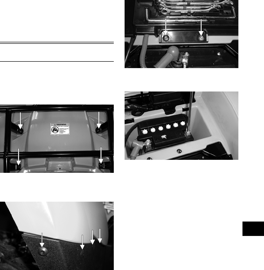
8-19
8
INSTALLING MUFFLER
1. Place the muffler into position engaging the
mounting lugs into the grommets; then slide the
muffler forward.
2. Install the two exhaust springs.
Rear Body Panel/Rack
REMOVING
1. Remove four machine screws and flanged nuts
securing the rear rack; then remove the rear
rack. Account for four bushings.
CD690A
2. Remove one shoulder screw and lock nut and
three plastic rivets (on each side) securing the
rear body panel to the footwells.
CD691A
3. Remove two machine screws securing the bat-
tery cover and remove the cover.
CD687A
4. Disconnect the battery (negative cable first);
then remove the battery.
CD688
5. Disconnect the taillight/brakelight; then remove
the gas tank cap and lift off the rear body panel.
Install the gas tank cap.
NOTE: If the front body panel has not been
removed, the left-side and right-side panels and
the two machine screws must be removed (see
Front Body Panel/Side Panels in this section).
CLEANING AND INSPECTING
NOTE: Whenever a part is worn excessively,
cracked, or damaged in any way, replacement is
necessary.
1. Clean all rear body panel components with
parts-cleaning solvent and soap and water.
2. Inspect side panels and rear body panel for
cracks and loose rivets.
3. Inspect threaded areas of all mounting bosses
for stripping.
4. Inspect for missing decals.
FOR ARCTIC CAT ATV DISCOUNT PARTS CALL 606-678-9623 OR 606-561-4983
www.mymowerparts.com
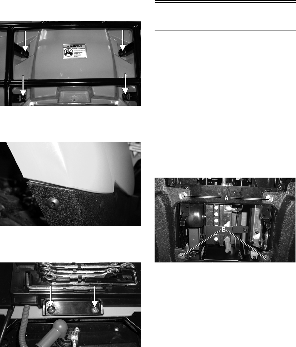
8-20
INSTALLING
1. Remove the gas tank cap and set the rear body
panel in position; then install the cap and con-
nect the taillight/brakelight connector.
2. Place the rear rack in position with four bush-
ings and secure with four machine screws and
flanged nuts. Tighten securely.
CD690A
3. Install one shoulder screw and three plastic riv-
ets (on each side) to secure the front of the rear
body panel to the footwells.
CD691
4. Place the battery into the battery box; then con-
nect the battery (positive cable first) and secure
with the battery cover.
CD687A
5. Secure the front and rear panels with two
machine screws; then install the left and right
side panels.
NOTE: If the front body panel has not been
installed, see Front Body Panel/Side Panels in this
section.
6. Place the seat into position making sure it locks
securely.
Side Storage Box
(TBX Models)
REMOVING
1. Rotate the cargo box latch handle (located on
the left and right sides between the cargo box
and the rear tire) and fully raise the cargo box.
2. Pull the seat lock lever forward (located below
the right side of the seat), raise the front end of
the seat, and slide it forward and off the ATV.
3. Remove the two cap screws (located inside the
side storage box) securing the box to the foot-
rest.
4. Remove the screw securing the box to the side
panel.
5. Remove cap screws (A and B) securing the box
to the frame.
CD045A
CLEANING AND INSPECTING
NOTE: Whenever a part is worn excessively,
cracked, or damaged in any way, replacement is
necessary.
1. Clean all side storage box components with soap
and water.
2. Inspect the box for cracks, tears, and loose
mounting hardware.
3. Inspect the box hatch O-ring seals for cuts or
tears.
FOR ARCTIC CAT ATV DISCOUNT PARTS CALL 606-678-9623 OR 606-561-4983
www.mymowerparts.com
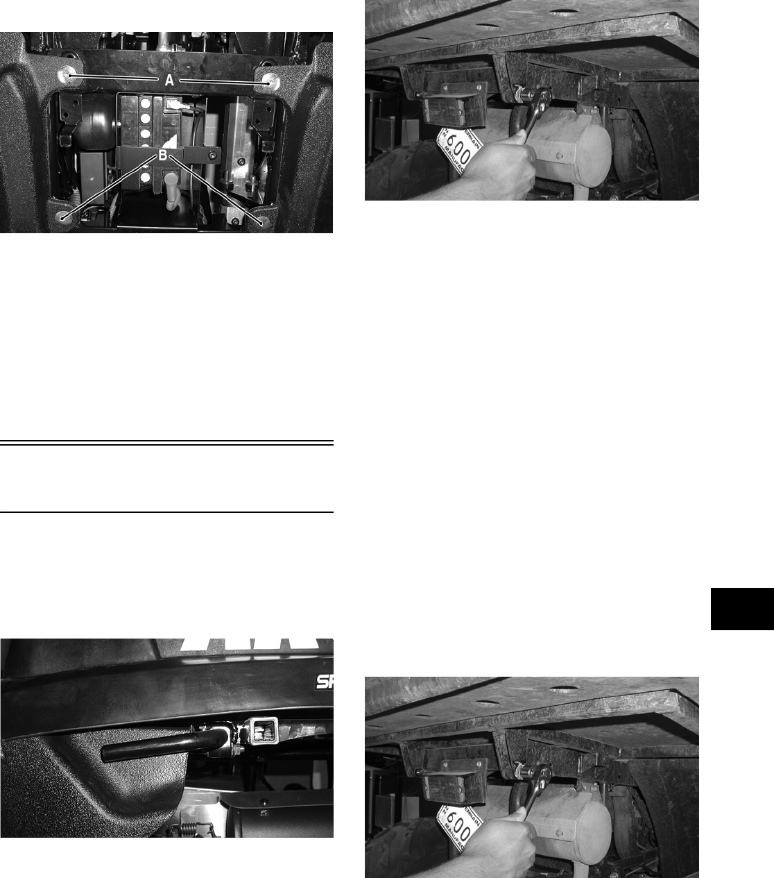
8-21
8
INSTALLING
1. Place the side storage box into position on the
frame; then secure with the two cap screws (A
and B). Tighten cap screws to specifications.
CD045A
2. Secure the box to the side panel with the exist-
ing screw.
3. Secure the box to the footrest with existing hard-
ware. Tighten securely.
4. Install the seat.
5. Lower the cargo box and press down firmly on
the front of the box. The cargo box will automat-
ically lock into position.
Cargo Box
(TBX Models)
REMOVING
1. Rotate the cargo box latch handle (located on
the left and right sides between the cargo box
and the rear tire) and fully raise the cargo box.
CD771
2. Remove the nut from the lower end of the box
lift support.
3. Remove the two cap screws and lock nuts secur-
ing the cargo box to the frame; then remove the
cargo box and discard the lock nuts.
CD122
NOTE: Never reuse a lock nut. Once a lock nut
has been removed, it must be replaced with a new
lock nut.
CLEANING AND INSPECTING
NOTE: Whenever a part is worn excessively,
cracked, or damaged in any way, replacement is
necessary.
1. Clean all cargo box components with soap and
water.
2. Inspect the cargo box for cracks, tears, and loose
mounting hardware.
3. Inspect the welds of the cargo box frame for
cracking or bending.
4. Inspect the cargo box gate latches for smooth
operation.
INSTALLING
1. Place the cargo box into position on the frame.
Secure with cap screws and new lock nuts.
Tighten to specifications.
CD122
FOR ARCTIC CAT ATV DISCOUNT PARTS CALL 606-678-9623 OR 606-561-4983
www.mymowerparts.com
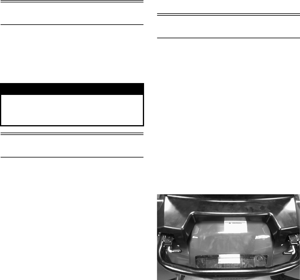
8-22
2. While an assistant holds the cargo box in the
raised position, secure the lower end of the box
lift support to the frame with the cap screw and
nut.
3. Lower the cargo box and press down firmly on
the front of the box. It will automatically lock
into position.
Adjusting Headlight
The headlights can be adjusted vertically and hori-
zontally. The geometric center of the HIGH beam
light zone is to be used for vertical and horizontal
aiming.
To check/adjust headlight beam, see Section 2.
Taillight Assembly
REMOVING
1. Unplug the three-prong connector and free the
taillight wiring harness from the frame.
2. Remove the torx-head cap screws securing the
taillight assembly to the frame. Account for any
washers.
3. Remove the taillight assembly.
INSPECTING
NOTE: Whenever a part is worn excessively,
cracked, or damaged in any way, replacement is
necessary.
1. Inspect wiring harness, three-prong connector,
lens, base, cap screws, and socket for damage.
2. Inspect all wires for corroding, pinching, and
cracking.
3. Inspect the bulb for wattage, voltage, and proper
operation.
INSTALLING
1. Place the assembly into position on the frame
and secure with torx-head cap screws and any
washers.
2. Tighten the cap screws securely.
3. Route the wiring harness over the rear frame;
then connect the three-prong connector.
Seat
NOTE: Some components may vary from model
to model. The technician should use discretion
and sound judgment.
REMOVING/INSTALLING
1. To remove the seat, lift up on the latch release
(located at the rear of the seat). Raise the rear of
the seat and slide it rearward.
2. To lock the seat into position, slide the front of
the seat into the seat retainers and push down
firmly on the rear of seat. The seat should auto-
matically lock into position.
REMOVING/INSTALLING (TRV)
1. To remove the rear seat, pull the two latch han-
dles to the rear and rotate them to the vertical
position.
CF226
2. Lift the rear of the seat up; then pull slightly to
the rear and lift the seat off the mountings.
! WARNING
Do not operate the ATV unless the headlight beam is
adjusted properly. An incorrectly adjusted beam will
not provide the operator the optimum amount of
light.
FOR ARCTIC CAT ATV DISCOUNT PARTS CALL 606-678-9623 OR 606-561-4983
www.mymowerparts.com
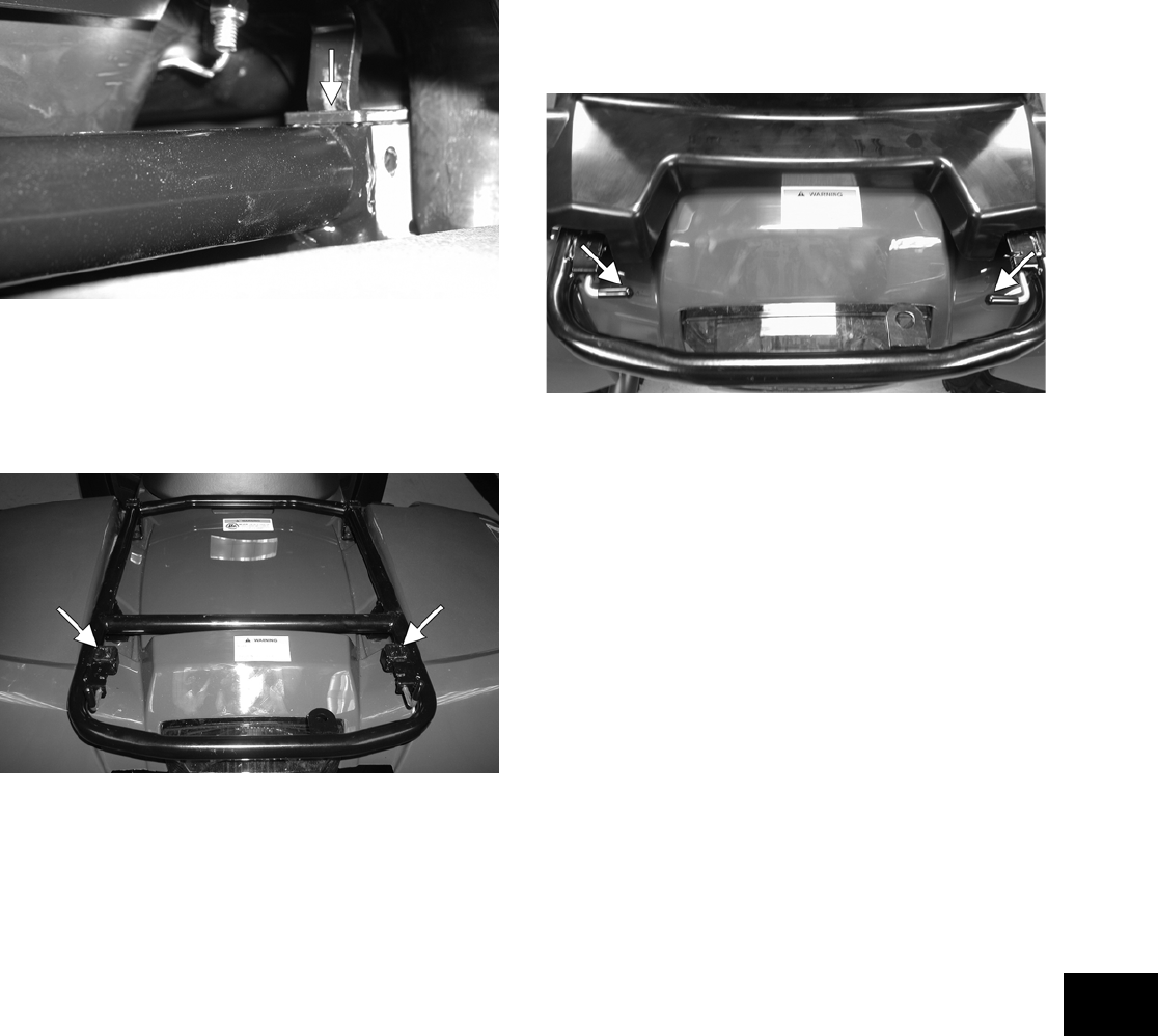
8-23
8
CF227A
3. To lock the seat into position, engage the two
front mounting lugs into the mounting rack; then
holding down firmly on the front of the seat,
push the seat forward until the rear tabs engage
the rear mounting latches.
CF229A
4. Lock the seat into position by pulling the two
latch handles to the rear and rotating them to the
horizontal position.
CF226A
NOTE: The rear seat must be removed prior to
removing the front seat.
5. To remove the front seat, pull the seat lock lever
up (located at the rear of the seat). Raise the rear
end of the seat and slide it rearward.
6. To lock the seat into position, slide the front of
the seat into the seat retainers and push down
firmly on rear of seat. The seat should automati-
cally lock into position.
FOR ARCTIC CAT ATV DISCOUNT PARTS CALL 606-678-9623 OR 606-561-4983
www.mymowerparts.com

9-1
9
SECTION 9 — CONTROLS/INDICATORS
TABLE OF
CONTENTS
Hand Brake Lever/Master Cylinder Assembly.…….. 9-2
Throttle Control ………..……………..…………….……….. 9-3
Gearshift Pedal (Manual Transmission)………..…….. 9-5
Drive Selector..…………….…………….………….……….. 9-5
Front Differential Lock ……………………………………... 9-5
Shift Lever ……….………….…………….…………….…….. 9-5
Speedometer/Tachometer/LCD….…………….……….. 9-6
FOR ARCTIC CAT ATV DISCOUNT PARTS CALL 606-678-9623 OR 606-561-4983
www.mymowerparts.com
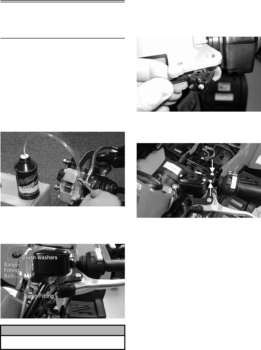
9-2
Hand Brake Lever/
Master Cylinder
Assembly
NOTE: The master cylinder is a non-serviceable
component; it must be replaced as an assembly.
REMOVING
1. Slide a piece of flexible tubing over one of the
wheel bleeder valves and direct the other end
into a container. Remove the reservoir cover;
then open the bleeder valve. Allow the brake
fluid to drain completely.
NOTE: Compressing the brake lever several
times will quicken the draining process.
AF637D
2. Place an absorbent towel around the connection
to absorb brake fluid. Remove the banjo-fitting
from the master cylinder. Account for two crush
washers and a banjo-fitting bolt.
DE059A
3. Remove the circlip and pivot pin securing the
brake lever to the master cylinder housing; then
remove the brake lever and set aside.
4. Dislodge the brakelight switch from the master
cylinder housing by gently pressing it toward
the pivot pin hole in the housing; then lay it
aside leaving the switch and wiring harness con-
nected.
BC205
5. Remove the clamp screws securing the brake
housing to the handlebar; then remove the
assembly from the handlebar.
DE058A
INSPECTING
NOTE: Whenever a part is worn excessively,
cracked, or damaged in any way, replacement is
necessary.
1. Inspect the pin securing the brake lever for wear.
2. Inspect the brake lever for elongation of the
pivot hole.
3. Inspect the reservoir for cracks and leakage.
4. Inspect the banjo-fitting for cracks and deterio-
ration and the condition of the fittings (threaded
and compression).
5. Inspect the brakelight switch for corrosion,
cracks, missing or broken mounting tabs, or bro-
ken and frayed wiring.
NOTE: If the brakelight switch is determined to
be not serviceable, see Section 5.
! CAUTION
Brake fluid is highly corrosive. Do not spill brake
fluid on any surface of the ATV.
FOR ARCTIC CAT ATV DISCOUNT PARTS CALL 606-678-9623 OR 606-561-4983
www.mymowerparts.com
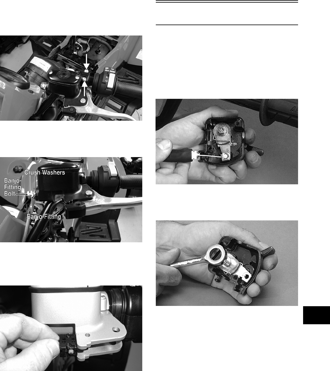
9-3
9
INSTALLING
1. Position the brake housing on the handlebar.
Secure with clamp screws; then tighten securely.
DE058A
2. Using two new crush washers, connect the
banjo-fitting to the master cylinder; then secure
with the banjo-fitting bolt.
DE059A
3. Gently press the brakelight switch into the hous-
ing (left to right) until the mounting tabs snap
into the four locating holes; then install the
brake lever, pivot pin, and circlip.
BC206
4. Bleed the brake system (see Section 2).
Throttle Control
REMOVING
1. Remove the two machine screws securing the
throttle control to the handlebar.
2. Slide the grommet out of the lower half of the
throttle control; then remove the cable from the
actuator arm.
AF676D
3. Remove the cap screw, lock washer, and washer
securing the actuator arm to the throttle control
lever.
AF677D
4. Remove the actuator arm and account for a
bushing. Note the position of the return spring
for installing purposes.
FOR ARCTIC CAT ATV DISCOUNT PARTS CALL 606-678-9623 OR 606-561-4983
www.mymowerparts.com
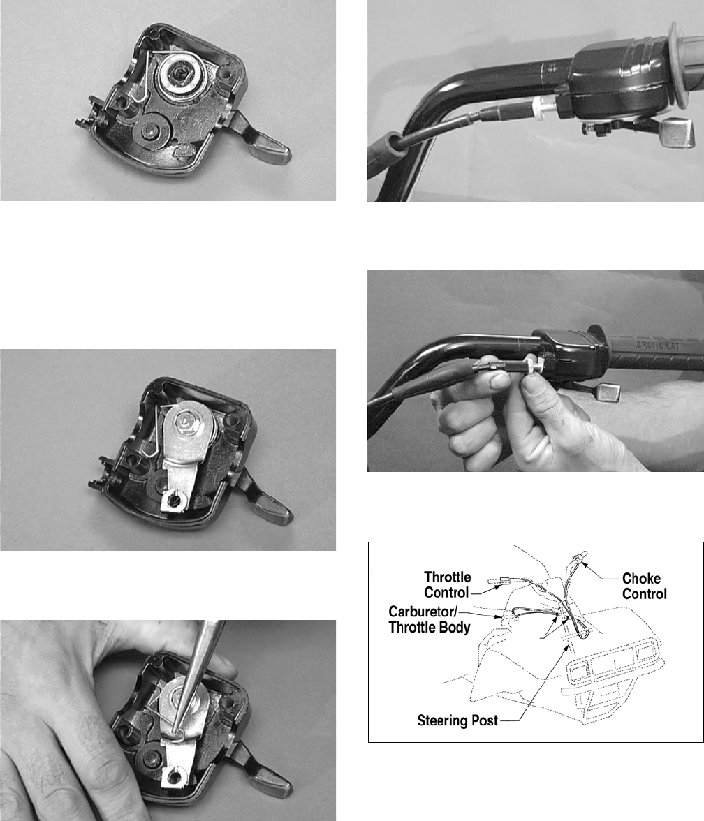
9-4
AF678D
INSTALLING
1. Place the return spring into the throttle control;
then place the bushing and actuator arm into
position. Secure with the cap screw, lock
washer, and washer.
AF679D
2. Using a pair of needle-nose pliers, place the
spring into position on the actuator arm.
AF680D
3. Place the two halves of the throttle control onto
the handlebars and secure with the two machine
screws.
ADJUSTING
1. Slide the boot back to reveal the jam nut; then
loosen the jam nut.
AF682D
2. Rotate the adjuster sleeve until 0.5-1.0 mm
(0.02-0.04 in.) is attained.
AL611D
3. Secure the adjustment by tightening the jam nut;
then slide the boot over the jam nut.
0732-412
FOR ARCTIC CAT ATV DISCOUNT PARTS CALL 606-678-9623 OR 606-561-4983
www.mymowerparts.com
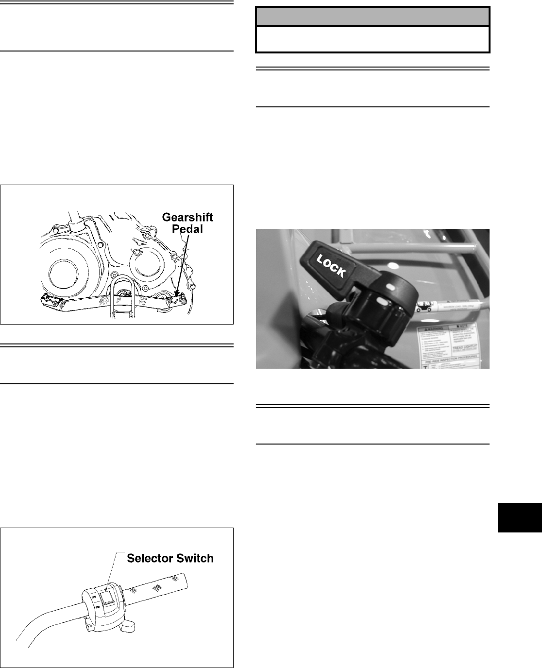
9-5
9
Gearshift Pedal
(Manual Transmission)
The gearshift pedal is attached to a ratchet mecha-
nism in the transmission. Each time a gear is
selected, the gearshift pedal will return to its normal
position ready to select the next gear. To return to
neutral, press down repeatedly (once for each gear)
on the front of the pedal. Shift into gears by pressing
down on the back of the pedal once for each gear.
The ratchet mechanism makes it impossible to
upshift or downshift more than one gear at a time.
ATV0078C
Drive Selector
The automatic drive selector allows the operator to
operate in either 2-wheel drive (rear wheels) or
4-wheel drive (all wheels). For normal riding on
flat, dry, hard surfaces, 2-wheel drive should be suf-
ficient. In situations of aggressive trail conditions,
4-wheel drive would be the desired choice.
To either engage or disengage the front wheels,
move the switch to the 4WD position or to the 2WD
position.
738-422A
Front Differential Lock
Certain ATV models are equipped with a front dif-
ferential lock. The front differential lock allows the
operator to mechanically lock the differential to
apply equal power to both front wheels. To engage
the front differential lock, rotate the handle fully
clockwise to LOCK; to disengage the front differen-
tial lock, rotate the handle fully counterclockwise to
UNLOCK.
KX016A
To adjust the differential lock cable, see Section 2.
Shift Lever
REMOVING
1. Remove the E-clip securing the shift rod to the
engine shift arm.
2. Remove two cap screws, two self-tapping
screws, and three nylon ties securing the
left-side splash panel and remove the panel.
3. Remove the axle and nut securing the shift lever
to the upper shift arm; then remove the shift
lever. Account for a spring and two O-rings.
4. Using two open-end wrenches, remove the lock
nut securing the shift rod to the upper shift arm.
Remove the shift rod and discard the lock nut.
NOTE: Never reuse a lock nut. Once a lock nut
has been removed, it must be replaced with a new
lock nut.
! CAUTION
Do not attempt to either engage or disengage the
front differential while the ATV is moving.
FOR ARCTIC CAT ATV DISCOUNT PARTS CALL 606-678-9623 OR 606-561-4983
www.mymowerparts.com
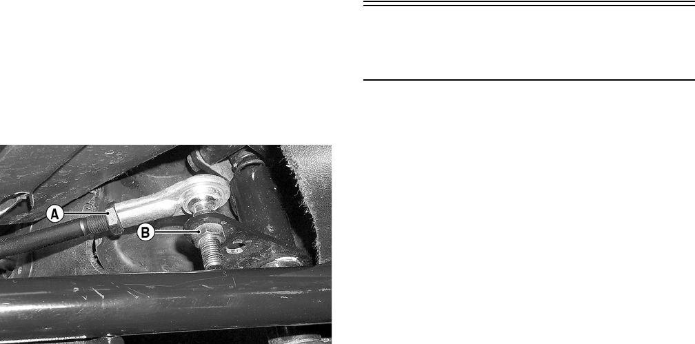
9-6
INSTALLING
1. Place the shift rod into position on the engine
shift arm and secure with the existing E-clip.
2. Using a new lock nut (B), secure the shift rod to
the upper shift arm; then using two open-end
wrenches, tighten securely.
AF941A
3. Place the spring into position between the upper
shift arm and shift lever; then making sure the
O-rings are in place on the axle, secure the shift
lever to the arm with the existing axle and nut.
4. Check shift lever adjustment (see Section 2);
then tighten jam nut (A) securely.
5. Install the left-side splash panel.
Speedometer/
Tachometer/LCD
REPLACING
To replace the speedometer, use the following pro-
cedure.
1. Remove the two reinstallable rivets securing the
instrument pod; then remove the ignition switch
retaining ring.
2. Remove the two nuts securing the mounting
studs; then remove the speedometer and discon-
nect the multi-pin connector.
3. Mount the speedometer and secure with the two
nuts; then connect the multi-pin connector.
4. Install the instrument pod and secure with the
reinstallable rivets.
5. Secure the ignition switch with the retaining
ring.
FOR ARCTIC CAT ATV DISCOUNT PARTS CALL 606-678-9623 OR 606-561-4983
www.mymowerparts.com

10-1
10
SECTION 10 — AIDS FOR MAINTENANCE
TABLE OF
CONTENTS
Torque Specifications
(400/500 — Manual Transmission)…………..……… 10-2
Torque Specifications
(400/500 — Automatic Transmission/650 H1) …… 10-3
Torque Specifications (700 EFI) ………………………. 10-5
Tightening Torque (General Bolts) …………………… 10-7
Torque Conversions …………..………….…………….… 10-7
FOR ARCTIC CAT ATV DISCOUNT PARTS CALL 606-678-9623 OR 606-561-4983
www.mymowerparts.com

10-2
Torque Specifications
(400/500 — Manual Transmission)
DRIVE TRAIN COMPONENTS
Part Part Bolted To Torque
kg-m ft-lb
Engine
(Lower Rear/Front)
Frame 5.5 40.0
Front Differential* Frame/Differential
Bracket
6.2 45.0
Pinion Housing Differential
Housing
2.9-3.5 21.0-
25.0
Differential Housing
Cover***
Differential
Housing
2.9-3.5 21.0-
25.0
Drive Bevel Gear Nut*** Shaft 10.0 72.0
Differential Gear Case*** Hub 2.3-3.0 16.5-
22.0
Lock Collar Differential
Housing
17.3 125.0
Hub Nut Shaft/Axle (max) 27.6 200.0
Oil Drain Plug Front Differential/
Rear Drive
0.5 3.5
Oil Fill Plug Front Differential/
Rear Drive
2.2 16.0
Oil Drain Plug Engine 2.2 16.0
Inspection Plug Front Differential/
Rear Drive
0.5 3.5
Wheel Hub 5.5 40.0
Oil Fitting (400) Engine 0.8 6.0
EXHAUST COMPONENTS
Exhaust Pipe Engine 2.8 20.0
ELECTRICAL COMPONENTS
Coil* Frame 1.7 12.0
Ground Wire Engine 1.1 8.0
STEERING COMPONENTS
Handlebar Block Steering Post 2.8 20.0
Steering Post Bearing
Housing
Frame 2.8 20.0
Steering Post Bearing
Flange
Frame 2.8 20.0
Lower Steering Bearing
Washer Cap Screw***
Steering Post 5.5 40.0
Tie Rod End Knuckle/Steering
Post
4.2 30.0
BRAKE COMPONENTS
Part Part Bolted To Torque
kg-m ft-lb
Brake Disc* Hub 2.1 15.0
Brake Hose Caliper 2.8 20.0
Brake Hose Master Cylinder 2.8 20.0
Brake Hose Auxiliary Brake Cyl-
inder
2.8 20.0
Master Cylinder (Rear) Frame 3.5 25.0
Master Cylinder Cover Master Cylinder 0.1 1.0
Auxiliary Brake Pedal Lever Axle 3.5 25.0
Hydraulic Caliper Knuckle/Axle
Retainer Assembly
2.8 20.0
Auxiliary Caliper Knuckle/Axle
Retainer Assembly
2.8 20.0
CHASSIS COMPONENTS
Footrest Frame (8 mm) 2.8 20.0
Footrest Frame (10 mm) 5.5 40.0
Shift Lever* Shift Axle 1.1 8.0
SUSPENSION COMPONENTS (Front)
A-Arm Frame 4.8 35.0
Ball Joint Cap Screw Knuckle 4.8 35.0
Shock Absorber Frame 4.8 35.0
Shock Absorber Upper A-Arm 4.8 35.0
Knuckle A-Arm 4.8 35.0
SUSPENSION COMPONENTS (Rear)
Axle Retainer Assembly Axle Housing 5.5 40.0
Shock Absorber (Upper) Frame 4.8 35.0
Shock Absorber (Lower) Lower A-Arm 2.8 20.0
A-Arm Frame 4.8 35.0
Swing Arm Axle Housing/Case 4.8 35.0
Knuckle A-Arm 4.8 35.0
FOR ARCTIC CAT ATV DISCOUNT PARTS CALL 606-678-9623 OR 606-561-4983
www.mymowerparts.com

10-3
10
* w/Blue Loctite #243
** w/Red Loctite #271
*** w/Green Loctite #609
Torque Specifications
(400/500 — Automatic
Transmission/650 H1)
ENGINE/TRANSMISSION
Part Part Bolted To Torque
kg-m ft-lb
Clutch Shoe Crankshaft 13.0 94.0
Clutch Sleeve Hub Countershaft 10.0 72.0
Crankcase Half (6 mm) Crankcase Half 0.9-1.3 6.5-9.5
Crankcase Half (8 mm) Crankcase Half 2-2.4 14.5-
17.0
Cylinder Head
(Cap Screw)
Cylinder 3.8 27.5
Cylinder Head
(6 mm Nut)
Cylinder 1.1 8.0
Cylinder Head (8 mm Nut) Cylinder 2.5 18.0
Cylinder Head Cover Cylinder Head 1.0 7.0
Left-Side Cover Crankcase Half 0.9-1.3 6.5-9.5
Mechanical Water Pump
Impeller
Pump Shaft 1.05 7.5
Oil Pump Drive Gear Crank Balancer
Shaft
8.0 58.0
Oil Pump* Crankcase 1.0 7.0
Output Shaft Gear Output Shaft 10.0 72.0
Rear Output Shaft Output Joint 2.8 20.0
Recoil Starter Left-Side Cover 0.8 6.0
Reverse Cam Stopper
Housing
Crankcase 2.3 16.5
Right-Side Cover Crankcase 0.9-1.3 6.5-9.5
Rotor/Flywheel Nut Crankshaft 16.0 116.0
Shift Stop Housing Crankcase 2.3 16.5
Cam Sprocket** Camshaft 1.5 11.0
Starter Cup Crankshaft 3.5 25.0
Spark Plug Engine 1.7 12.0
DRIVE TRAIN COMPONENTS
Part Part Bolted To Torque
kg-m ft-lb
Engine Mounting
Through-Bolt (400/500)
Frame 5.5 40.0
Engine (650 H1) Engine Cradle 5.5 40.0
Engine Cradle (650
H1/TRV)**
Rubber Mount 3.5 25.0
Rubber Mount (650
H1/TRV)
Frame Bracket 4.8 35.0
Front Differential* Frame/Differential
Bracket
6.2 45.0
Rear Output Joint
Assembly
Engine 2.8 20.0
Input Housing Differential
Housing
2.9-3.5 21.0-
25.0
Differential Housing
Cover***
Differential
Housing
2.9-3.5 21.0-
25.0
Drive Bevel Gear Nut*** Shaft 10.0 72.0
Differential Gear Case*** Hub 2.3-3 16.5-22
Lock Collar Differential
Housing
17.3 125.0
Hub Nut Shaft/Axle (max) 27.6 200.0
Oil Drain Plug Front Differential/
Rear Drive
0.5 3.5
Oil Fill Plug Front Differential/
Rear Drive
2.2 16.0
Oil Drain Plug Engine 2.2 16.0
Inspection Plug Rear Drive 0.5 3.5
Wheel Hub 5.5 40.0
EXHAUST COMPONENTS
Exhaust Pipe (400/500) Engine 2.8 20.0
Exhaust Pipe (650 H1) Engine 2.8 20.0
ELECTRICAL COMPONENTS
Coil* Frame 1.7 12.0
Ground Wire Engine 1.1 8.0
FOR ARCTIC CAT ATV DISCOUNT PARTS CALL 606-678-9623 OR 606-561-4983
www.mymowerparts.com

10-4
* w/Blue Loctite #243
** w/Red Loctite #271
*** w/Green Loctite #609
STEERING COMPONENTS
Part Part Bolted To Torque
kg-m ft-lb
Handlebar Block Steering Post 2.8 20.0
Steering Post Bearing
Housing
Frame 2.8 20.0
Steering Post Bearing
Flange
Frame 2.8 20.0
Lower Steering Bearing
Washer Cap Screw***
Steering Post 5.5 40.0
Tie Rod End Knuckle/Steering
Post
4.2 30.0
BRAKE COMPONENTS
Brake Disc* Hub 2.1 15.0
Brake Hose Caliper 2.8 20.0
Brake Hose Master Cylinder 2.8 20.0
Brake Hose Auxiliary Brake Cali-
per
2.8 20.0
Master Cylinder Cover Master Cylinder 0.1 1.0
Auxiliary Brake Pedal Lever Axle 3.5 25.0
Hydraulic Caliper Knuckle 2.8 20.0
Auxiliary Caliper Knuckle 2.8 20.0
CHASSIS COMPONENTS
Footrest Frame (8 mm) 2.8 20.0
Footrest Frame (10 mm) 5.5 40.0
Shift Lever* Shift Axle 1.1 8.0
SUSPENSION COMPONENTS (Front)
A-Arm Frame 4.8 35.0
Ball Joint Cap Screw Knuckle 4.8 35.0
Shock Absorber Frame 4.8 35.0
Shock Absorber Upper A-Arm 4.8 35.0
Knuckle A-Arm 4.8 35.0
SUSPENSION COMPONENTS (Rear)
A-Arm Frame 4.8 35.0
Shock Absorber (Upper) Frame 4.8 35.0
Shock Absorber (Lower) Lower A-Arm 2.8 20.0
Knuckle A-Arm 4.8 35.0
SUSPENSION COMPONENTS (Rear) TBX Model
Shock Absorber Frame 4.8 35.0
Shock Absorber A-Arm 2.8 20.0
Tilt Box Frame ATV Frame 3.3 24.0
Cargo Box (Plastic) Tilt Box Frame 1.7 12.0
Side Box Frame 2.8 20.0
Side Box Footwell 1.1 8.0
Rear CV Joint** Engine 2.8 20.0
ENGINE/TRANSMISSION
(400/500 — Automatic Transmission)
Part Part Bolted To Torque
kg-m ft-lb
Clutch Shoe Crankshaft 13.0 94.0
Clutch Cover/Housing
Assembly
Crankcase 1.1 8.0
Crankcase Half (6 mm) Crankcase Half 0.9-1.3 6.5-9.5
Crankcase Half (8 mm) Crankcase Half 2-2.4 14.5-17
Cylinder Head
(Cap Screw)
Crankcase 3.8 27.5
Cylinder Head (6 mm) Cylinder 1.1 8.0
Cylinder Head (8 mm) Cylinder 2.5 18.0
Cylinder Head Cover Cylinder Head 1.0 7.0
Driven Pulley Nut** Fixed Face 10.4-11.8 75.0-
85.0
Fixed Driven Clutch Shaft 10.4-11.8 75.0-
85.0
Ground Wire Engine 1.1 8.0
Magneto Cover Crankcase 1.1 8.0
Mechanical Water Pump
Impeller
Pump Shaft 1.05 7.5
Movable Drive Face** Driveshaft 10.4-11.8 75.0-
85.0
Oil Pump Drive Gear Crank Balancer
Shaft
5.0 36.0
Output Shaft Gear Output Shaft 10.0 72.0
Recoil Starter Left-Side Cover 0.8 6.0
Rotor/Flywheel Nut Crankshaft 16.0 116.0
Cam Sprocket** Camshaft 1.5 11.0
Starter Cup Crankshaft 3.5 25.0
V-Belt Cover Crankcase 1.1 8.0
Spark Plug Engine 1.7 12.0
FOR ARCTIC CAT ATV DISCOUNT PARTS CALL 606-678-9623 OR 606-561-4983
www.mymowerparts.com

10-5
10
* w/Blue Loctite #243
** w/Red Loctite #271
*** w/Green Loctite #609
Torque Specifications
(700 EFI)
ENGINE/TRANSMISSION
(650 H1)
Part Part Bolted To Torque
kg-m ft-lb
Clutch Shoe Crankshaft 31.8 230.0
Clutch Cover/Housing
Assembly
Crankcase 1.1 8.0
Crankcase Half (6 mm) Crankcase Half 0.9-1.3 6.5-9.5
Crankcase Half (8 mm) Crankcase Half 2.8 20.0
Cylinder Head
(Cap Screw)
Crankcase 5.5 40.0
Cylinder Head (6 mm) Cylinder 1.1 8.0
Cylinder Head (8 mm) Cylinder 2.5 18.0
Cylinder Head Cover Cylinder Head 1.1-1.2 8.0-9.0
Driven Pulley Nut Fixed Face 13.5 97.5
Fixed Driven** Clutch Shaft 13.5 97.5
Ground Wire Engine 1.1 8.0
Magneto Cover Crankcase 1.1 8.0
Mechanical Water Pump
Impeller
Pump Shaft 1.05 7.5
Movable Drive Face** Driveshaft 10.4-11.8 75-85
Oil Pump Drive Gear Crank Balancer
Shaft
8.5 61.5
Output Shaft Gear Output Shaft 8.5 61.5
Outer Magneto Cover Left-Side Cover 0.8 6.0
Recoil Starter
(Certain 650 H1 Models)
Left-Side Cover 0.8 6.0
Rotor/Flywheel Nut Crankshaft 14.5 105.0
Cam Sprocket** Camshaft 1.35 9.8
Starter Cup/Spacer Crankshaft 3.8 27.5
V-Belt Cover Crankcase 1.1 8.0
Spark Plug Engine 1.7 12.0
DRIVE TRAIN COMPONENTS
Part Part Bolted To Torque
kg-m ft-lb
Engine Mounting
Through-Bolt
Frame 5.5 40.0
Engine Mount (Rear) Frame 5.5 40.0
Front Differential**** Frame/Differential
Bracket
6.2 45.0
Rear Drive Gear Case Frame 6.2 45.0
Pinion Housing Differential Housing 2.9-3.5 21.0-
25.0
Differential Housing
Cover***
Differential Housing 2.9-3.5 21.0-
25.0
Drive Bevel Gear
Nut***
Shaft 11.0-
13.0
79.5-
94.0
Lock Collar Differential Housing 17.3 125.0
Hub Nut Shaft/Axle (max) 27.6 200.0
Oil Drain Plug Front Differential/
Rear Drive
0.5 3.5
Oil Fill Plug Front Differential/
Rear Drive
2.2 16.0
Oil Drain Plug Engine 2.2 16.0
Inspection Plug Front Differential 0.5 3.5
Wheel Hub 5.5 40.0
EXHAUST COMPONENTS
Muffler Frame 2.8 20.0
Exhaust Pipe Cylinder Head 1.9 14.0
ELECTRICAL COMPONENTS
Coil**** Frame 1.7 12.0
Ground Wire Engine 1.1 8.0
STEERING COMPONENTS
Handlebar Block Steering Post 2.8 20.0
Steering Post Bearing
Housing
Frame 2.8 20.0
Steering Post Bearing
Flange
Frame 2.8 20.0
Lower Steering Bearing
Washer Cap Screw***
Steering Post 5.5 40.0
Tie Rod End Knuckle/Steering
Post
4.2 30.0
FOR ARCTIC CAT ATV DISCOUNT PARTS CALL 606-678-9623 OR 606-561-4983
www.mymowerparts.com

10-6
* w/Blue Loctite #242
** w/Red Loctite #271
*** w/Green Loctite #609
****w/Blue Loctite #243
BRAKE COMPONENTS
Part Part Bolted To Torque
kg-m ft-lb
Brake Disc**** Hub 2.1 15.0
Brake Hose Caliper 2.8 20.0
Brake Hose Master Cylinder 2.8 20.0
Brake Hose Auxiliary Brake Cylinder 2.8 20.0
Master Cylinder Cover Master Cylinder 0.1 1.0
Auxiliary Brake Pedal Lever Axle 3.5 25.0
Hydraulic Caliper Suspension Knuckle 2.8 20.0
CHASSIS COMPONENTS
Footrest Frame (8 mm) 2.8 20.0
Footrest Frame (10 mm) 5.5 40.0
Shift Lever**** Shift Axle 1.1 8.0
SUSPENSION COMPONENTS (Front)
A-Arm Frame 4.8 35.0
Ball Joint Cap Screw Knuckle 4.8 35.0
Shock Absorber Frame 4.8 35.0
Shock Absorber Upper A-Arm 4.8 35.0
Knuckle A-Arm 4.8 35.0
SUSPENSION COMPONENTS (Rear)
A-Arm Frame 5.5 40.0
Shock Absorber (Upper) Frame 4.8 35.0
Shock Absorber (Lower) Lower A-Arm 2.8 20.0
Knuckle A-Arm 4.8 35.0
ENGINE/TRANSMISSION
Clutch Shoe Crankshaft 15.0 108.0
Clutch Cover/Housing
Assembly
Crankcase 0.9 6.5
Crankcase Half (6 mm) Crankcase Half 1.0 7.0
Crankcase Half (8mm) Crankcase Half 2.6 19.0
Cylinder Head (Cap Screw) Crankcase (Step 1)
(Step 2)
2.5
3.7
18.0
27.0
Cylinder Head (6 mm) Cylinder 1.0 7.0
Cylinder Head Cover Cylinder (Step 1)
Head (Step 2)
1.0
1.4
7.0
10.0
Driven Pulley Nut Fixed Face 10.9 79.0
Fixed Driven** Clutch Shaft 10.9 79.0
Ground Wire Engine 1.1 8.0
Magneto Cover Crankcase 1.1 8.0
Movable Drive Face** Driveshaft 10.9 79.0
Oil Pump Drive Gear Crank Balancer
Shaft
15.0 108.0
Output Shaft Gear Output Shaft 10.0 72.0
Recoil Starter Left-Side Cover 0.8 6.0
Rotor/Flywheel Nut Crankshaft 16.0 116.0
Cam Idler Shaft Cylinder Head 4.1 29.5
Starter Cup Crankshaft 3.8 27.5
V-Belt Cover Crankcase 0.9 6.5
Spark Plug Engine 1.1 8.0
FOR ARCTIC CAT ATV DISCOUNT PARTS CALL 606-678-9623 OR 606-561-4983
www.mymowerparts.com
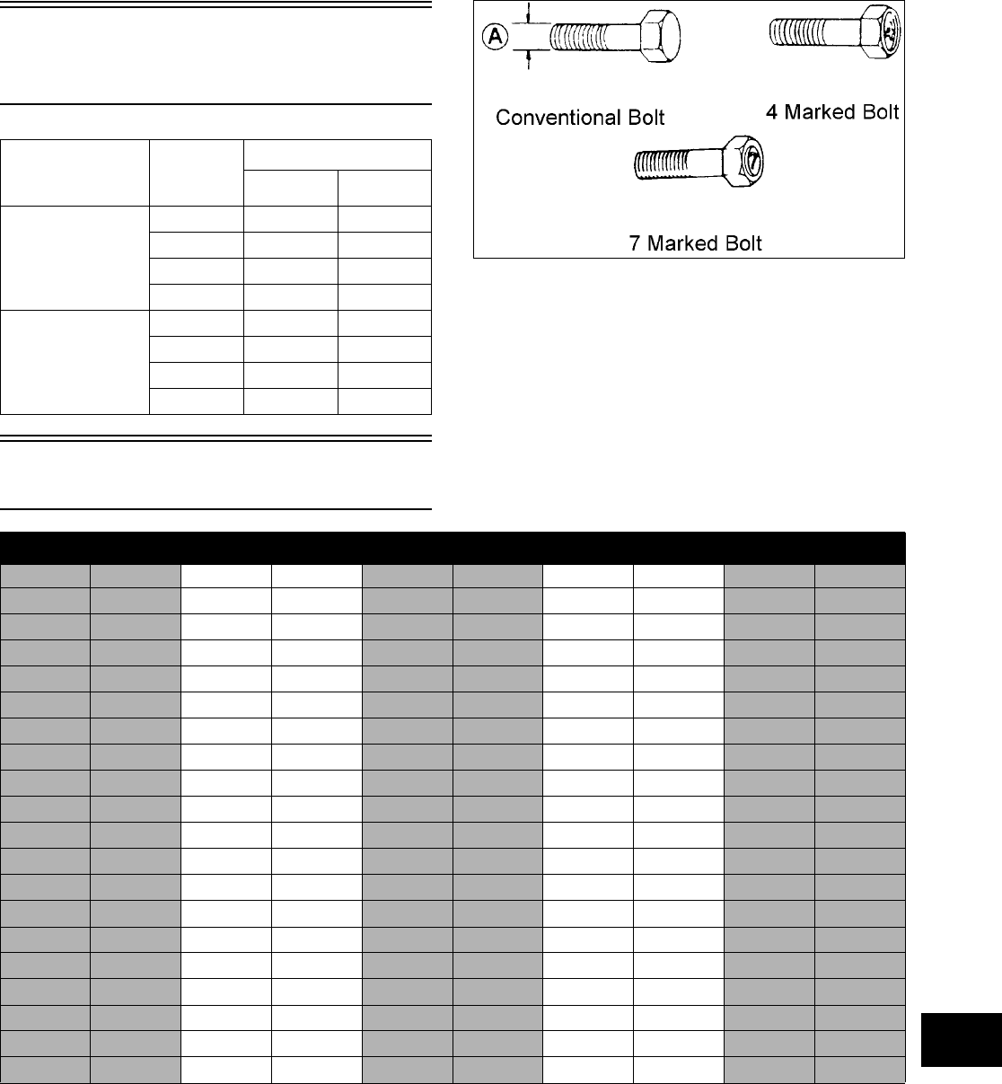
10-7
10
Tightening Torque
(General Bolts)
Torque Conversions
Type of Bolt
Thread
Diameter
A (mm)
Tightening Torque
kg-m ft-lb
(Conventional or
4 Marked Bolt)
5 0.2-0.4 1.5-3.0
6 0.4-0.7 3.0-5.0
8 1.0-1.6 7.0-11.5
10 2.2-3.5 16.0-25.5
(7 Marked Bolt) 5 0.3-0.6 2.0-4.5
6 0.8-1.2 6.0-8.5
8 1.8-2.8 13.0-20.0
10 4.0-6.0 29.0-43.5
ft-lb kg-m ft-lb kg-m ft-lb kg-m ft-lb kg-m ft-lb kg-m
10.1 21 2.9 41 5.7 61 8.4 81 11.2
20.3 22 3.0 42 5.8 62 8.6 82 11.3
30.4 23 3.2 43 5.8 63 8.7 83 11.5
40.6 24 3.3 44 6.1 64 8.9 84 11.6
50.7 25 3.5 45 6.2 65 9.0 85 11.8
60.8 26 3.6 46 6.4 66 9.1 86 11.9
71.0 27 3.7 47 6.5 67 9.3 87 12.0
81.1 28 3.9 48 6.6 68 9.4 88 12.2
91.2 29 4.0 49 6.8 69 9.5 89 12.3
10 1.4 30 4.2 50 6.9 70 9.7 90 12.5
11 1.5 31 4.3 51 7.1 71 9.8 91 12.6
12 1.7 32 4.4 52 7.2 72 10.0 92 12.8
13 1.8 33 4.6 53 7.3 73 10.1 93 12.9
14 1.9 34 4.7 54 7.5 74 10.2 94 13.0
15 2.1 35 4.8 55 7.6 75 10.4 95 13.1
16 2.2 36 5.0 56 7.7 76 10.5 96 13.3
17 2.4 37 5.1 57 7.9 77 10.7 97 13.4
18 2.5 38 5.3 58 8.0 78 10.8 98 13.6
19 2.6 39 5.4 59 8.2 79 10.9 99 13.7
20 2.8 40 5.5 60 8.3 80 11.1 100 13.8
FOR ARCTIC CAT ATV DISCOUNT PARTS CALL 606-678-9623 OR 606-561-4983
www.mymowerparts.com

11-1
11
SECTION 11 — TROUBLESHOOTING
TABLE OF
CONTENTS
Engine ………………….…………….…………….…………. 11-2
Drive…………….…………….…………….…………….…… 11-5
Fuel System (400/500/650 H1) ………………..……… 11-6
Fuel System (700 EFI) ………………..………….……… 11-6
Electrical………….…………….…………….…………….… 11-7
Steering/Suspension ………….…………….……………. 11-9
Brakes ……………….………….…………….…………….. 11-10
FOR ARCTIC CAT ATV DISCOUNT PARTS CALL 606-678-9623 OR 606-561-4983
www.mymowerparts.com

11-2
Engine
NOTE: A Condition/Remedy marked with an
asterisk (*) is for manual transmission models
only.
Problem: Engine will not start or is hard to start (Compression too low)
Condition Remedy
1. Valve clearance out of adjustment 1. Adjust clearance
2. Valve guides worn — seated poorly 2. Repair — replace guides
3. Valves mistimed 3. Adjust valve timing
4. Piston rings worn excessively 4. Replace rings
5. Cylinder bore worn 5. Replace — rebore cylinder
6. Spark plug seating poorly 6. Tighten plug
7. Starter motor cranks too slowly — does not turn 7. See Electrical in this section
Problem: Engine will not start or is hard to start (No spark)
Condition Remedy
1. Spark plug fouled 1. Clean — replace plug
2. Spark plug wet 2. Clean — dry plug
3. Magneto defective 3. Replace magneto
4. CDI unit/ECU defective 4. Replace CDI unit/ECU
5. Ignition coil defective 5. Replace ignition coil
6. High-tension lead open — shorted 6. Replace high tension lead
Problem: Engine will not start or is hard to start (No fuel reaching the carburetor/fuel injector)
Condition Remedy
1. Gas tank vent hose obstructed 1. Clean vent hose
2. Carburetor float valve defective 2. Replace valve
3. Fuel hose obstructed 3. Clean — replace hose
4. Fuel screens obstructed 4. Clean — replace inlet screen — valve screen
5. Fuel pump defective 5. Replace fuel pump
Problem: Engine stalls easily
Condition Remedy
1. Spark plug fouled 1. Clean plug
2. Magneto defective 2. Replace magneto
3. CDI unit/ECU defective 3. Replace CDI unit/ECU
4. Carburetor jets/fuel injector obstructed 4. Clean jets/replace fuel injector
5. Valve clearance out of adjustment 5. Adjust clearance
Problem: Engine noisy (Excessive valve chatter)
Condition Remedy
1. Valve clearance too large 1. Adjust clearance
2. Valve spring(s) weak — broken 2. Replace spring(s)
3. Rocker arm — rocker arm shaft worn 3. Replace arm — shaft
4. Camshaft worn 4. Replace camshaft
5. Valve tappets worn 5. Replace tappets
Problem: Engine noisy (Noise seems to come from piston)
Condition Remedy
1. Piston — cylinder worn 1. Replace — service piston — cylinder
2. Combustion chamber carbon buildup 2. Clean chamber
3. Piston pin — piston pin bore worn 3. Replace — service pin — bore
4. Piston rings — ring groove(s) worn 4. Replace rings — piston
Problem: Engine noisy (Noise seems to come from timing chain)
Condition Remedy
1. Chain stretched 1. Replace chain
2. Sprockets worn 2. Replace sprockets
3. Tension adjuster malfunctioning 3. Repair — replace adjuster
FOR ARCTIC CAT ATV DISCOUNT PARTS CALL 606-678-9623 OR 606-561-4983
www.mymowerparts.com

11-3
11
Problem: Engine noisy (Noise seems to come from clutch)
Condition * Remedy *
1. Crankshaft splines — bearings worn 1. Replace crankshaft — bearings
2. Countershaft — hub splines worn 2. Replace countershaft — hub
3. Clutch plate teeth worn 3. Replace clutch plate(s)
4. Driven — drive clutch plates distorted — broken 4. Replace clutch plate(s)
5. Clutch dampers weak 5. Replace dampers
Problem: Engine noisy (Noise seems to come from crankshaft)
Condition Remedy
1. Bearing worn — burned 1. Replace bearing
2. Lower rod-end bearing worn — burned 2. Replace bearing
3. Connecting rod side clearance too large 3. Replace thrust washer(s)
Problem: Engine noisy (Noise seems to come from transmission)
Condition Remedy
1. Gears worn — rubbing 1. Replace gears
2. Splines worn 2. Replace shaft(s)
3. Primary gears worn — rubbing 3. Replace gears
4. Bearings worn 4. Replace bearings
5. Bushing worn 5. Replace bushing
Problem: Engine noisy (Noise seems to come from secondary-transmission/left-side cover)
Condition * Remedy *
1. Gears — shaft(s) worn 1. Replace gears — shafts
2. Bearing(s)/bushing(s) damaged 2. Replace bearing(s)/bushing(s)
Problem: Engine noisy (Noise seems to come from secondary bevel gear and final driven shaft)
Condition Remedy
1. Drive — driven bevel gears damaged — worn 1. Replace gears
2. Backlash excessive 2. Adjust backlash
3. Tooth contact improper 3. Adjust contact
4. Bearing damaged 4. Replace bearing
5. Gears worn — rubbing 5. Replace gears
6. Splines worn 6. Replace shaft(s)
7. Final driven shaft thrust clearance too large 7. Replace thrust washer(s)
Problem: Clutch slipping
Condition * Remedy *
1. Release roller out of adjustment — loss of free-play 1. Adjust clutch bolts 1 & 2
2. Clutch springs weak 2. Replace springs
3. Clutch shoes worn 3. Replace shoes
4. Pressure disc worn — distorted 4. Replace disc
5. Clutch plates (driven — drive) distorted 5. Replace plates
Problem: Clutch dragging
Condition * Remedy *
1. Clutch release roller out of adjustment — too much
free-play
1. Adjust clutch bolts 1 & 2
2. Clutch springs weak 2. Replace springs
3. Pressure disc — clutch plates distorted 3. Replace disc — plates
4. Clutch release mechanism worn — damaged 4. Adjust — replace mechanism
Problem: Transmission will not shift
Condition * Remedy *
1. Gearshift cam broken 1. Replace cam
2. Gearshift forks distorted 2. Replace forks
3. Gearshift shaft worn 3. Replace shaft
4. Clutch release mechanism worn — damaged 4. Adjust — replace mechanism
5. Gearshift linkage adjusted improperly 5. Adjust linkage
FOR ARCTIC CAT ATV DISCOUNT PARTS CALL 606-678-9623 OR 606-561-4983
www.mymowerparts.com

11-4
Problem: Transmission will not shift back
Condition * Remedy *
1. Reverse shift cam broken 1. Replace cam
2. Shift shafts rubbing — sticking 2. Replace shafts
3. Gearshift forks distorted — worn 3. Replace forks
4. Gearshift lever return spring broken — damaged 4. Replace spring
Problem: Transmission jumps out of gear
Condition * Remedy *
1. Shifting gears (driveshaft — countershaft) worn 1. Replace gears
2. Gearshift forks distorted — worn 2. Replace forks
3. Cam stopper spring (gearshift cam) weak 3. Replace spring
4. Gearshift lever stopper pin worn 4. Replace pin
Problem: Secondary-transmission will not shift or shift back
Condition * Remedy *
1. Sliding dog broken — worn 1. Replace dog
2. Gearshift fork broken — worn 2. Replace fork
3. Shift lever out of adjustment 3. Adjust lever
4. Gearshift cam worn 4. Replace cam
5. Cam stopper spring weak 5. Replace spring
6. Gearshift fork shaft worn 6. Replace shaft
Problem: Engine idles poorly
Condition Remedy
1. Valve clearance out of adjustment 1. Adjust clearance
2. Valve seating poor 2. Replace — service seats — valves
3. Valve guides defective 3. Replace guides
4. Rocker arms — arm shaft worn 4. Replace arms — shafts
5. Magneto defective 5. Replace magneto
6. CDI unit/ECU defective 6. Replace CDI unit/ECU
7. Spark plug fouled — gap too wide 7. Adjust gap — replace plug
8. Ignition coil defective 8. Replace ignition coil
9. Float out of adjustment 9. Adjust float height
10. Jets obstructed 10. Clean jets
11. Pilot screw setting improper 11. Adjust pilot screw
12. Fuel injector obstructed 12. Replace fuel injector
Problem: Engine runs poorly at high speed
Condition Remedy
1. High RPM “cut out” against RPM limiter 1. Shift into higher gear — decrease speed
2. Valve springs weak 2. Replace springs
3. Valve timing out of adjustment 3. Adjust timing
4. Cams — rocker arms — tappets worn 4. Replace cams — arms — tappets
5. Spark plug gap too narrow 5. Adjust gap
6. Ignition coil defective 6. Replace ignition oil
7. Float level too low 7. Adjust float height
8. Air cleaner element obstructed 8. Clean element
9. Fuel hose obstructed 9. Clean or replace hose
10. Fuel pump defective 10. Replace fuel pump
Problem: Exhaust smoke dirty or heavy
Condition Remedy
1. Oil (in the engine) overfilled — contaminated 1. Drain excess oil — replace oil
2. Piston rings — cylinder worn 2. Replace — service rings — cylinder
3. Valve guides worn 3. Replace guides
4. Cylinder wall scored — scuffed 4. Replace — service cylinder
5. Valve stems worn 5. Replace valves
6. Stem seals defective 6. Replace seals
FOR ARCTIC CAT ATV DISCOUNT PARTS CALL 606-678-9623 OR 606-561-4983
www.mymowerparts.com

11-5
11
Drive
Problem: Engine lacks power
Condition Remedy
1. Valve clearance incorrect 1. Adjust clearance
2. Valve springs weak 2. Replace springs
3. Valve timing incorrect 3. Re-time valve gear
4. Piston ring(s) — cylinder worn 4. Replace — service rings — cylinder
5. Valve seating poor 5. Repair seats
6. Spark plug fouled 6. Clean — replace plug
7. Rocker arms — shafts worn 7. Replace arms — shafts
8. Spark plug gap incorrect 8. Adjust gap — replace plug
9. Carburetor jets/fuel injector obstructed 9. Clean jets — replace injector
10. Float level out of adjustment 10. Adjust float height
11. Air cleaner element obstructed 11. Clean element
12. Oil (in the engine) overfilled — contaminated 12. Drain excess oil — change oil
13. Intake manifold leaking air 13. Tighten — replace manifold
14. Cam chain worn 14. Replace cam chain
Problem: Engine overheats
Condition Remedy
1. Carbon deposit (piston crown) excessive 1. Clean piston
2. Oil low 2. Add oil
3. Octane low — gasoline poor 3. Drain — replace gasoline
4. Oil pump defective 4. Replace pump
5. Oil circuit obstructed 5. Clean circuit
6. Gasoline level (in float chamber) too low 6. Adjust float height
7. Intake manifold leaking air 7. Tighten — replace manifold
8. Coolant level low 8. Fill — examine system for leaks
9. Fan malfunctioning 9. Check fan fuse — replace fan
10. Fan switch malfunctioning 10. Replace fan switch
11. Thermostat stuck — closed 11. Replace thermostat
12. Radiator hoses — cap damaged — obstructed 12. Clear obstruction — replace hoses
Problem: Power not transmitted from engine to wheels
Condition Remedy
1. Rear axle shaft serration worn — broken 1. Replace shaft
Problem: Power not transmitted from engine to either front wheel
Condition Remedy
1. Secondary drive — driven gear teeth broken 1. Replace gear(s)
2. Propeller shaft serration worn — broken 2. Replace shaft
3. Coupling damaged 3. Replace coupling
4. Coupling joint serration worn — damaged 4. Replace joint
5. Front drive — driven bevel gears broken — damaged 5. Replace gear(s)
6. Front differential gears/pinions broken — damaged 6. Replace gears — pinions
7. Sliding dog/shaft/fork worn — damaged 7. Replace gear(s)
8. Front drive axle worn — damaged 8. Replace axle
9. Front drive axle serration worn — damaged 9. Replace axle
FOR ARCTIC CAT ATV DISCOUNT PARTS CALL 606-678-9623 OR 606-561-4983
www.mymowerparts.com

11-6
Fuel System
(400/500/650 H1)
Fuel System
(700 EFI)
Problem: Starting impaired
Condition Remedy
1. Starter jet obstructed 1. Clean jet
2. Starter jet passage obstructed 2. Clean passage
3. Carburetor leaking air 3. Replace gasket
4. Gas contaminated 4. Drain gas tank and fill with clean gas
Problem: Idling or low speed impaired
Condition Remedy
1. Slow jet obstructed — loose 1. Clean — tighten jet
2. Slow jet outlet obstructed 2. Clean outlet
3. Low speed fuel screw setting incorrect 3. Adjust screw
4. Float height incorrect 4. Adjust float height
5. TPS out of adjustment 5. Adjust TPS
Problem: Medium or high speed impaired
Condition Remedy
1. High RPM “cut out” against RPM limiter 1. Shift into higher gear — decrease RPM speed
2. Main jet obstructed 2. Clean main jet
3. Needle jet obstructed 3. Clean needle jet
4. Vacuum piston not operating properly 4. Check piston operation
5. Filter obstructed 5. Clean filter
6. Float height incorrect 6. Adjust float height
Problem: Overflow and fuel level fluctuations
Condition Remedy
1. Float valve worn — damaged 1. Replace valve
2. Float valve spring broken 2. Replace spring
3. Float not working properly 3. Adjust float height — replace float
4. Float valve dirty 4. Clean valve
5. Float height too high — too low 5. Adjust float height
Problem: Starting impaired
Condition Remedy
1. Gas contaminated 1. Drain gas tank and fill with clean gas
Problem: Idling or low speed impaired
Condition Remedy
1. TPS out of adjustment 1. Adjust TPS
Problem: Medium or high speed impaired
Condition Remedy
1. High RPM “cut out” against RPM limiter 1. Decrease RPM speed
FOR ARCTIC CAT ATV DISCOUNT PARTS CALL 606-678-9623 OR 606-561-4983
www.mymowerparts.com

11-7
11
Electrical
Problem: Spark absent or weak
Condition Remedy
1. Ignition coil defective 1. Replace ignition coil
2. Spark plug defective 2. Replace plug
3. Magneto defective 3. Replace magneto
4. CDI unit/ECU defective 4. Replace CDI unit/ECU
5. Pick-up coil defective 5. Replace pick-up coil
Problem: Spark plug fouled with carbon
Condition Remedy
1. Mixture too rich 1. Adjust carburetor
2. Idling RPM too high 2. Adjust carburetor
3. Gasoline incorrect 3. Change to correct gasoline
4. Air cleaner element dirty 4. Clean element
5. Spark plug incorrect (too cold) 5. Replace plug
6. Valve seals cracked — missing 6. Replace seals
7. Oil rings worn — broken 7. Replace rings
Problem: Spark plug electrodes overheat or burn
Condition Remedy
1. Spark plug incorrect (too hot) 1. Replace plug
2. Engine overheats 2. Service cooling system
3. Spark plug loose 3. Tighten plug
4. Mixture too lean 4. Adjust carburetor
Problem: Magneto does not charge
Condition Remedy
1. Lead wires/connections shorted — loose — open 1. Repair — replace — tighten lead wires
2. Magneto coils shorted — grounded — open 2. Replace magneto coils
3. Regulator/rectifier defective 3. Replace regulator/rectifier
Problem: Magneto charges, but charging rate is below the specification
Condition Remedy
1. Lead wires shorted — open — loose (at terminals) 1. Repair — tighten lead wires
2. Stator coils (magneto) grounded — open 2. Replace stator coils
3. Regulator/rectifier defective 3. Replace regulator/rectifier
4. Electrolyte low 4. Add distilled water
5. Cell plates (battery) defective 5. Replace battery
Problem: Magneto overcharges
Condition Remedy
1. Internal battery short circuited 1. Replace battery
2. Regulator/rectifier resistor damaged — defective 2. Replace resistor
3. Regulator/rectifier poorly grounded 3. Clean — tighten ground connection
Problem: Charging unstable
Condition Remedy
1. Lead wire intermittently shorting 1. Replace lead wire
2. Magneto internally shorted 2. Replace magneto
3. Regulator/rectifier defective 3. Replace regulator/rectifier
FOR ARCTIC CAT ATV DISCOUNT PARTS CALL 606-678-9623 OR 606-561-4983
www.mymowerparts.com

11-8
Problem: Starter button not effective
Condition Remedy
1. Battery charge low 1. Charge — replace battery
2. Switch contacts defective 2. Replace switch
3. Starter motor brushes not seating 3. Repair — replace brushes
4. Starter relay defective 4. Replace relay
5. Emergency stop — ignition switch off 5. Turn on switches
6. Wiring connections loose — disconnected 6. Connect — tighten — repair connections
Problem: Battery “sulfation” (Acidic white powdery substance or spots on surfaces of cell plates)
Condition Remedy
1. Charging rate too low — too high 1. Replace battery
2. Battery electrolyte insufficient 2. Keep electrolyte to prescribed level
3. Specific gravity too low 3. Charge battery — add distilled water
4. Battery run-down — damaged 4. Replace battery
5. Electrolyte contaminated 5. Replace battery
Problem: Battery discharges too rapidly
Condition Remedy
1. Electrolyte contaminated 1. Replace battery
2. Specific gravity too low 2. Charge battery — add distilled water
3. Charging system not charging 3. Check magneto — regulator/rectifier — circuit
connections
4. Cell plates overcharged — damaged 4. Replace battery — correct charging system
5. Battery short-circuited 5. Replace battery
6. Specific gravity too low 6. Charge battery
Problem: Battery polarity reversed
Condition Remedy
1. Battery incorrectly connected 1. Reverse connections — replace battery — repair
damage
FOR ARCTIC CAT ATV DISCOUNT PARTS CALL 606-678-9623 OR 606-561-4983
www.mymowerparts.com

11-9
11
Steering/Suspension
Problem: Handling too heavy or stiff
Condition Remedy
1. Front wheel alignment incorrect 1. Adjust alignment
2. Lubrication inadequate 2. Lubricate appropriate components
3. Tire inflation pressure low 3. Adjust pressure
4. Tie rod ends seizing 4. Replace tie rod ends
5. Linkage connections seizing 5. Repair — replace connections
Problem: Steering oscillation
Condition Remedy
1. Tires inflated unequally 1. Adjust pressure
2. Wheel(s) wobbly 2. Replace wheel(s)
3. Wheel hub cap screw(s) loose — missing 3. Tighten — replace cap screws
4. Wheel hub bearing worn — damaged 4. Replace bearing
5. Tie rod ends worn — loose 5. Replace — tighten tie rod ends
6. Tires defective — incorrect 6. Replace tires
7. A-arm bushings damaged 7. Replace bushings
8. Bolts — nuts (frame) loose 8. Tighten bolts — nuts
Problem: Steering pulling to one side
Condition Remedy
1. Tires inflated unequally 1. Adjust pressure
2. Front wheel alignment incorrect 2. Adjust alignment
3. Wheel hub bearings worn — broken 3. Replace bearings
4. Frame distorted 4. Repair — replace frame
5. Shock absorber defective 5. Replace shock absorber
Problem: Tire wear rapid or uneven
Condition Remedy
1. Wheel hub bearings worn — loose 1. Replace bearings
2. Front wheel alignment incorrect 2. Adjust alignment
3. Tire inflation pressure incorrect 3. Adjust pressure
Problem: Steering noise
Condition Remedy
1. Caps screws — nuts loose 1. Tighten cap screws — nuts
2. Wheel hub bearings broken — damaged 2. Replace bearings
3. Lubrication inadequate 3. Lubricate appropriate components
Problem: Suspension too soft
Condition Remedy
1. Spring(s) weak 1. Replace spring(s)
2. Shock absorber damaged 2. Replace shock absorber
3. Shock absorber preload too low 3. Adjust shock absorber preload
Problem: Suspension too stiff
Condition Remedy
1. A-arm-related bushings worn 1. Replace bushing
2. Shock absorber preload too high 2. Adjust shock absorber preload
Problem: Suspension noisy
Condition Remedy
1. Cap screws (suspension system) loose 1. Tighten cap screws
2. A-arm-related bushings worn 2. Replace bushings
FOR ARCTIC CAT ATV DISCOUNT PARTS CALL 606-678-9623 OR 606-561-4983
www.mymowerparts.com

11-10
Brakes
Problem: Rear wheel oscillation
Condition Remedy
1. Rear wheel hub bearings worn — loose 1. Replace bearings
2. Tires defective — incorrect 2. Replace tires
3. Wheel rim distorted 3. Replace rim
4. Wheel hub cap screws loose 4. Tighten cap screws
5. Axle shaft nut loose (Manual Transmission) 5. Tighten nut (Manual Transmission)
6. Auxiliary brake adjusted incorrectly 6. Adjust brake
7. Rear suspension arm-related bushing worn 7. Replace bushing
8. Rear shock absorber damaged 8. Replace shock absorber
9. Rear suspension arm nut loose 9. Tighten nut
Problem: Braking poor
Condition Remedy
1. Pad worn 1. Replace pads
2. Pedal free-play excessive 2. Replace pads
3. Brake fluid leaking 3. Repair — replace hydraulic system component(s)
4. Hydraulic system spongy 4. Bleed hydraulic system — correct or repair leaks
5. Master cylinder/brake cylinder seal worn 5. Replace master cylinder
Problem: Brake lever travel excessive
Condition Remedy
1. Hydraulic system entrapped air 1. Bleed hydraulic system
2. Brake fluid low 2. Add fluid to proper level
3. Brake fluid incorrect 3. Drain system — replace with correct fluid
4. Piston seal — cup worn 4. Replace master cylinder
Problem: Brake fluid leaking
Condition Remedy
1. Connection joints loose 1. Tighten joint
2. Hose cracked 2. Replace hose
3. Piston seal worn 3. Replace brake caliper
FOR ARCTIC CAT ATV DISCOUNT PARTS CALL 606-678-9623 OR 606-561-4983
www.mymowerparts.com