- 22.11.2022
Коды ошибок сплит-систем AUX серий FJ Inverter, Prime
При возникновении неисправности код ошибки автоматически отображается на дисплее лицевой панели внутреннего блока кондиционера AUX.
| Код ошибки | Описание |
| E1 | Ошибка датчика комнатной температуры воздуха |
| E2 | Ошибка датчика температуры теплообменника наружного блока |
| E3 | Ошибка датчика температуры теплообменника внутреннего блока |
| E4 | Неисправность электродвигателя вентилятора внутреннего блока |
Коды ошибок сплит-систем AUX серии JD, DE Inverter
| № п/п | Название ошибки | Код ошибки |
| 1 | Неисправность датчика комнатной температуры | E1 |
| 2 | Неисправность датчика температуры наружного теплообменника | E2 |
| 2 | Неисправность датчика температуры внутреннего теплообменника | E3 |
| 4 | Неисправность двигателя внутреннего вентилятора или двигателя постоянного тока с обратной связью | E4 |
| 5 | Неисправность внутренней и наружной связи | E5 |
| 6 | Неисправность двигателя наружного вентилятора постоянного тока | F0 |
| 7 | Модульная неисправность IPM | F1 |
| 8 | Модульная неисправность PFC | F2 |
| 9 | Неисправность в работе компрессора | F3 |
| 10 | Неисправность датчика температуры | F4 |
| 11 | Защита верхней крышки компрессора | F5 |
| 12 | Неисправность датчика температуры наружного воздуха | F6 |
| 13 | Защита от перенапряжения / понижения напряжения | F7 |
| 14 | Неисправность наружной модульной связи | F8 |
| 15 | Неисправность внешнего EEPROM (энергонезависимой памяти) | F9 |
| 16 | Неисправность датчика температуры всасывания (неисправность переключателя 4-ходового клапана) | FA |
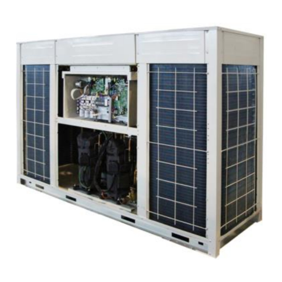
Коды ошибок для полупромышленных кондиционеров AUX
|
Код |
Определение кода ошибки |
Восстановление, да или нет |
Возможные причины проблемы |
| E0 | Недостаток хладагента |
Нет |
Возможные причины: внутренняя защита компрессора, в системе не хватает хладагента, обратный отказ 4-ходового клапана |
| E1 | TA (датчик температуры в помещении) является ненормальным |
Да |
Повреждение датчика. Плохой контакт датчика |
| E2 | TW (датчик температуры размораживания) является ненормальным |
Да |
Повреждение датчика. Плохой контакт датчика |
| E3 | TE (датчик внутренней катушки) является ненормальным |
Да |
Повреждение датчика. Плохой контакт датчика |
| E4 | Неисправность дренажной системы |
Да |
Повреждение водяного насоса. Повреждение переключателя уровня воды. Переключатель уровня воды заблокирован |
| E5 | Сбой связи проводного контроллера |
Да |
Ошибка последовательности проводов связи. Плохой контакт коммуникационного провода |
| E6 | Outdoor unit protection(phase sequence) |
Нет |
Фаза кабеля питания отсутствует. Ошибка последовательности фаз силового кабеля |
| E7 | TL (датчик температуры наружного конденсата) является ненормальным |
Да |
Повреждение датчика. Плохой контакт датчика |
| E8 | TP (датчик температуры разряда) является ненормальным |
Да |
Повреждение датчика. Плохой контакт датчика |
| E9 | Защита от низкого давления |
Да |
В системе не хватает хладагента |
| EA | Защита наружного блока (Температура разряда слишком высока) |
Нет |
Действие внешнего защитного устройства |
| F1 | Сбой связи между внутренним и наружным блоками |
Да |
Ошибка последовательности проводов связи. Плохой контакт коммуникационного провода |
| F2 | Защита от перегрева |
Да |
Система заблокирована или неисправен наружный вентилятор |
| F3 | Наружный вентилятор работает ненормально |
Да |
Плохой контакт наружного двигателя. Двигатель вышел из строя |
| F4 | Внутренний вентилятор неисправен |
Да |
Плохой контакт внутреннего двигателя. Двигатель вышел из строя |
| F5 | Датчик температуры наружного воздуха неисправен |
Да |
Повреждение датчика. Плохой контакт сенсора |
| F6 | Защита компрессора от перегрузки по току |
Нет |
Компрессор заблокирован. Низкое напряжение |
| F7 | Переключатель набора номера неисправен |
Да |
Неправильное положение переключателя |
| FB | Защита питания в помещении |
Да |
Неправильная проводка |
| F9 | Защита от высокого давления |
Да |
Конденсатор заблокирован. Ненормальная работа наружного вентилятора. Системная линия заблокирована |
Коды ошибок полупромышленных кондиционеров AUX моделей ALCa, ALCe, ALHi (R22, серия С2)
| Ошибка | Светодиодная индикация на внутреннем блоке | Индикация на проводном пульте | Состояние системы Ошибка связи |
| Ошибка связи | нет | Е5 | Остановлена |
| Авария дренажа1 | Светодиод таймера (желтого цвета) мигает 4 раза | Е4 | Остановлена |
| Перефазировка2, пониженное напряжение питания2 или низкое давление в системе3 | Светодиод таймера (желтого цвета) мигает 6 раз | Е6 | Остановлена |
| Неисправность датчика комнатной температуры | Мигает светодиод таймера (желтого цвета) | Е1 | Остановлена |
| Неисправность датчика температуры на испарителе | Светодиод таймера (желтого цвета) мигает 2 раза | Е3 | Остановлена |
| Неисправность датчика температуры на конденсаторе | Светодиод таймера (желтого цвета) мигает 2 раза | нет | Работает |
| Режим размораживая наружного блока | Мигает светодиод работы (зеленого цвета) | нет | Работает |
Сервисные мануалы

Service manual D inverter
pdf
,
3.97 MiB

Service manual D on-off
pdf
,
14.35 MiB

Service manual J inverter
pdf
,
17.76 MiB

Service manual J On-off
pdf
,
4.19 MiB

Service manual LK ON-OFF
pdf
,
5.48 MiB

Service_manual_LK_On_Off_30k, 36k
pdf
,
16.83 MiB

Service manual LK inverter
pdf
,
19.37 MiB

service manual LA LV Kids Inverter
pdf
,
5.49 MiB

Service manual FJ ON-OFF
pdf
,
2.16 MiB

Service manual Prime inverter
pdf
,
6.00 MiB

Q ON-OFF service manual
pdf
,
5.55 MiB

AUX Q Inverter Service manual
pdf
,
7.39 MiB

Free Match Сервисный мануал 2017
pdf
,
10.38 MiB

Free Match Сервисный мануал 2019
pdf
,
12.31 MiB

Free Match Сервисный мануал 2021
pdf
,
10.86 MiB

Free Match Сервисный мануал 2023
pdf
,
12.19 MiB
Сервисные мануалы полупромышленные

Сервисный мануал полупром on/off 2017
pdf
,
12.79 MiB

Сервисный мануал полупром on/off 2019
pdf
,
14.20 MiB

Сервисный мануал полупром on/off 2021
pdf
,
14.60 MiB

Сервисный мануал полупром Inverter 2017
pdf
,
8.79 MiB

Сервисный мануал полупром R32 2019
pdf
,
18.77 MiB
AUX коды ошибок
docx
,
136.37 KiB

AUX LCAC OnOff R410a Installation Operation Manual 2021
pdf
,
19.69 MiB
Сервисные мануалы ARV NEXT

Service Manual ARV NEXT
pdf
,
22.93 MiB

Service Manual ARV 6
pdf
,
19.97 MiB

AUX mini ARV Service manual
pdf
,
6.84 MiB

AUX ARV SERIES INDOOR UNIT
pdf
,
45.76 MiB
Сервисные мануалы Free Match
Free Match Сервисный мануал 2017
pdf
,
10.38 MiB
Free Match Сервисный мануал 2019
pdf
,
12.31 MiB
Free Match Сервисный мануал 2023
pdf
,
12.19 MiB
-
Contents
-
Table of Contents
-
Bookmarks
Related Manuals for AUX ARV Series
Summary of Contents for AUX ARV Series
-
Page 1
DC inverter ARV individual series Technical Manual DC Inverter ARV Individual Series… -
Page 2: Table Of Contents
DC inverter ARV individual series Part1 General Information 1.Features ………………..1 1.1 Energy Saving Technology …………………… 1 1.2 Convenience And Comfort ……………………. 2 1.3 Reliable & Stable ……………………..4 1.4 Intelligent Control ……………………..5 2.External Appearance …………….6 Outdoor unit ………………………. 6 Indoor units ………………………..
-
Page 3
DC inverter ARV individual series… -
Page 4: Features
DC inverter ARV individual series 1. Features 1.1 Energy Saving Technology Innovation technique for full DC inverter compressor High-performance, low-sound DC inverter compressor operates at a faster frequency, reducing start-up time. This helps the unit to bring the room temperature up to the set level quickly. …
-
Page 5: Convenience And Comfort
DC inverter ARV individual series Optimized designed heat exchanger. Double C-shape heat exchanger combined, large heat exchange area and high performance, enhance the efficiency of the system. Compact structure and space saving. 1.2 Convenience And Comfort Wide operation range No matter the ambient temperature is as high as 52℃…
-
Page 6
DC inverter ARV individual series Non-polarity communication 2-core shielded signal wire and non-polarity communication between outdoor and indoor unit, easy installation and make the system more reliable. Extend pipe length and height Thanks to DC inverter control technology, it is possible to design a system with longer piping length and higher level difference, makes the system more flexible and suitable for most types of buildings. -
Page 7: Reliable & Stable
Intelligent defrosting AUX intelligent defrosting technique extend the heating operation and decrease the frequency of defrosting. Result in stable room temperature, offer comfort life.
-
Page 8: Intelligent Control
Network control AUX has the independent central control software which can control up to 99 outdoor unit and 1024 indoor unit. The central control software can be combined with the BMS adapter ,such asBACnet and Modbus adapter.
-
Page 9: External Appearance
AUX-DC inverter ARV outdoor unit individual series technical manual 2.External Appearance 2.1 Outdoor unit Capacity(HP) Model ARV-H615/5R1B ARV-H670/5R1B ARV-H730/5R1B ARV-H780/5R1B ARV-H850/5R1B ARV-H900/5R1B 2.2 Indoor unit Type Appearance Capacity :kW 4-way cassette compact 4-way cassette 10.0 11.2 12.5 14.0 Ceiling & Floor 10.0…
-
Page 10: Nomenclatures
AUX-DC inverter ARV outdoor unit individual series technical manual 3.Nomenclatures 3.1 Outdoor Unit 3.2 Indoor unit…
-
Page 11
AUX-DC inverter ARV outdoor unit individual series technical manual Part2 Specification & Performance 1.Specifications ………………9 2. Dimensions ………………13 3. Refrigeration cycle diagram …………… 15 3.1 Piping diagrams ……………………..15 3.2 Refrigerant circuit ……………………..19 3.3 Wire Diagrams ……………………..21 3.4 Operation limits ……………………..24 3.5 Capacity Table ………………………25… -
Page 12: Specifications
AUX-DC inverter ARV outdoor unit individual series technical manual 1. Specifications Model ARV-H620/5R1IB ARV-H670/5R1IB ARV-H730/5R1IB AL-H220A5/MuR1D AL-H240A5/MuR1D AL-H260A5/MuR1D Factory Model IU(A) IU(A) IU(A) Factory Code 16105022000091 16105022000091 16105022000090 V~,Hz, Power Supply 380~415,50,3 380~415,50,3 380~415,50,3 Capacity 61.5 67.0 73.0 Cooling Input 18.7…
-
Page 13
AUX-DC inverter ARV outdoor unit individual series technical manual Fan Quantity a.Number Of Row b.Tube Pitch(a)x Row 22×19.05 22×19.05 22×19.05 Pitch(b) c.Fin Pitch Hydrophilic Hydrophilic Hydrophilic d.Fin Material Outdoor Coil aluminum fin aluminum fin aluminum fin e.Tube Outside φ7, Inner grooved φ7,… -
Page 14
AUX-DC inverter ARV outdoor unit individual series technical manual Model ARV-H780/5R1IB ARV-H850/5R1IB ARV-H900/5R1IB AL-H280A5/MuR1D AL-H300A5/MuR1D AL-H320A5/MuR1D Factory Model IU(A) IU(A) IU(A) Factory Code 16105022000090 16105022000089 16105022000089 V~,Hz, Power Supply 380~415,50,3 380~415,50,3 380~415,50,3 Capacity 78.5 85.0 90.0 Cooling Input 23.7 25.8 27.5… -
Page 15
AUX-DC inverter ARV outdoor unit individual series technical manual b.Tube Pitch(a)x Row 22×19.05 22×19.05 22×19.05 Pitch(b) c.Fin Pitch Hydrophilic Hydrophilic Hydrophilic d.Fin Material aluminum fin aluminum fin aluminum fin e.Tube Outside φ7, Inner grooved φ7, Inner grooved φ7, Inner grooved Dia.And Material… -
Page 16: Dimensions
AUX-DC inverter ARV outdoor unit individual series technical manual 2.Dimensions ARV-H615/5R1B, ARV-H670/5R1B (Unit: mm)
-
Page 17
AUX-DC inverter ARV outdoor unit individual series technical manual ARV-H730/5R1B, ARV-H785/5R1B, ARV-H850/5R1B,ARV-H900/5R1B (Unit: mm) Notes: Ensure necessary installation and maintenance space. If two rows of outdoor units, we suggest face to face, because easy to maintenance; no air short circuit. -
Page 18: Refrigeration Cycle Diagram
AUX-DC inverter ARV outdoor unit individual series technical manual 3. Refrigeration cycle diagram 3.1 Piping diagrams ARV-H615/5R1B, ARV-H670/5R1B…
-
Page 19
AUX-DC inverter ARV outdoor unit individual series technical manual… -
Page 20
AUX-DC inverter ARV outdoor unit individual series technical manual ARV-H730/5R1B, ARV-H780/5R1B, ARV-H850/5R1B,ARV-H900/5R1B… -
Page 21
AUX-DC inverter ARV outdoor unit individual series technical manual… -
Page 22: Refrigerant Circuit
AUX-DC inverter ARV outdoor unit individual series technical manual 3.2 Refrigerant circuit Code Component name Main function Driving module from unit electrical box will control the DC inverter DC inverter compressor operation, the compressor operation frequency range is compressor 20~120Hz.
-
Page 23
AUX-DC inverter ARV outdoor unit individual series technical manual liquid pipe stop valve Cut off indoor and outdoor side refrigerant flow. Gas pipe stop valve Cut off indoor and outdoor side refrigerant flow. Filter Filter lubricating oil, avoid oil return capillary block. -
Page 24: Wire Diagrams
DC inverter ARV Individual Series technical manual 3.3 Wire Diagrams ARV-H615/5R1B, ARV-H670/5R1B…
-
Page 25
DC inverter ARV Individual Series technical manual ARV-H730/5R1B, ARV-H780/5R1B, ARV-H850/5R1B,ARV-H900/5R1B… -
Page 26
DC inverter ARV Individual Series technical manual Fielding wiring Outdoor units wiring diagram Outdoor and indoor unit communication wiring diagram Communication wire Communication wire between IDUs between ODU and IDU… -
Page 27: Operation Limits
DC inverter ARV Individual Series technical manual 3.4Operation limits Cooling mode Heating mode…
-
Page 28: Capacity Table
DC inverter ARV Individual Series technical manual Capacity Table Cooling Capacity table ARV-H615/5R1B Combination Outdoor Indoor temperature(°C) Capacity temp. DB:20.8,WB:14 DB:23.3,WB:16 DB:25.8,WB:18 DB:27,WB:19 DB:28.2,WB:20 DB:30.7,WB:22 DB:32,WB:24 index (°CDB) 54.23 8.55 64.67 10.45 74.93 12.40 77.83 12.69 78.82 12.43 80.73 11.91 82.77 11.36…
-
Page 29
DC inverter ARV Individual Series technical manual 50.09 13.58 59.54 17.58 63.13 18.68 63.99 18.77 65.04 18.89 66.84 19.07 68.62 19.28 50.09 14.47 59.54 18.73 62.20 19.37 63.13 19.46 63.99 19.57 65.72 19.76 67.51 19.98 50.09 15.38 59.30 19.77 61.09 20.01 62.01 20.12… -
Page 30
DC inverter ARV Individual Series technical manual 41.76 11.19 49.66 14.33 57.82 17.86 61.77 19.20 63.56 19.29 63.00 19.44 64.49 19.61 41.76 11.91 49.66 15.25 57.82 19.01 61.77 19.83 63.56 19.94 62.20 20.07 63.00 20.26 41.44 12.60 49.42 15.92 57.26 19.88 61.21 20.37… -
Page 31
DC inverter ARV Individual Series technical manual 33.36 8.89 39.66 11.15 46.27 13.73 47.93 15.15 52.56 16.57 59.17 19.66 60.41 19.98 32.92 9.53 39.29 11.79 45.95 14.33 47.38 15.68 52.13 17.13 58.74 20.21 59.98 20.70 32.55 10.06 38.54 12.38 45.84 14.92 46.82 16.36… -
Page 32
DC inverter ARV Individual Series technical manual 24.71 6.76 29.52 8.19 34.35 9.89 36.26 10.82 39.10 11.49 43.92 13.58 48.61 15.54 24.15 7.19 29.22 8.64 33.79 10.53 35.70 11.38 38.54 12.10 43.37 14.27 48.05 16.23 22.48 7.73 27.42 9.25 31.99 11.29 33.79 12.07… -
Page 33
DC inverter ARV Individual Series technical manual ARV-H670/5R1B Combination Outdoor Indoor temperature(°C) Capacity temp. DB:20.8,WB:14 DB:23.3,WB:16 DB:25.8,WB:18 DB:27,WB:19 DB:28.2,WB:20 DB:30.7,WB:22 DB:32,WB:24 index (°CDB) 59.07 9.37 70.45 11.46 81.62 13.59 84.78 13.91 85.86 13.63 87.94 13.06 90.16 12.45 59.07 9.53 70.45 11.66 81.62 13.88… -
Page 34
DC inverter ARV Individual Series technical manual 54.57 16.86 64.59 21.68 66.55 21.94 67.55 22.06 68.49 22.18 70.59 22.41 72.53 22.63 54.30 18.04 63.99 22.75 66.08 22.79 67.02 22.95 67.89 23.10 69.51 23.20 72.20 23.30 53.83 18.98 63.51 23.55 65.80 23.73 66.41 23.85… -
Page 35
DC inverter ARV Individual Series technical manual 45.15 13.82 53.83 17.45 62.37 21.80 66.68 22.33 69.24 22.73 67.29 22.83 68.16 23.04 44.41 14.61 53.22 18.45 61.77 22.69 65.94 23.04 67.89 23.49 66.81 23.52 67.89 23.73 42.59 15.46 51.27 19.50 59.82 23.83 63.72 23.99… -
Page 36
DC inverter ARV Individual Series technical manual 35.46 11.03 41.98 13.57 49.93 16.35 51.00 17.94 56.25 19.66 63.39 22.83 65.07 23.50 33.51 11.68 40.37 14.28 47.97 17.08 49.32 18.65 54.44 20.33 61.64 23.50 62.98 24.20 31.69 12.45 38.29 14.95 46.36 17.61 47.10 19.17… -
Page 37
DC inverter ARV Individual Series technical manual 24.49 8.47 29.87 10.14 34.85 12.37 36.81 13.23 40.37 13.94 45.49 16.40 50.40 18.45 22.74 9.04 27.99 10.65 33.03 13.08 34.99 13.91 38.29 14.44 44.55 17.08 48.45 19.16 20.92 9.65 26.18 11.18 31.42 13.89 33.38 14.61… -
Page 38
DC inverter ARV Individual Series technical manual ARV-H730/5R1B Combination Outdoor Indoor temperature(°C) Capacity temp. DB:20.8,WB:14 DB:23.3,WB:16 DB:25.8,WB:18 DB:27,WB:19 DB:28.2,WB:20 DB:30.7,WB:22 DB:32,WB:24 index (°CDB) 64.09 10.10 76.43 12.35 88.55 14.65 91.98 15.00 93.15 14.69 95.41 14.08 97.82 13.42 64.09 10.27 76.43 12.57 88.55 14.96… -
Page 39
DC inverter ARV Individual Series technical manual 56.14 21.64 66.87 26.35 69.13 26.65 70.08 26.83 71.39 26.94 73.00 27.13 75.77 27.38 54.02 22.67 64.90 27.22 67.01 27.79 68.11 27.94 69.28 28.16 70.88 28.27 73.51 28.49 51.90 23.67 62.63 28.38 64.90 28.78 65.99 28.95… -
Page 40
DC inverter ARV Individual Series technical manual 44.31 6.59 52.71 7.91 61.47 9.26 65.70 10.45 69.93 11.13 78.55 12.72 87.09 14.43 44.31 6.68 52.71 8.02 61.47 9.40 65.70 10.58 69.93 11.32 78.55 12.96 87.09 14.63 44.31 6.79 52.71 8.17 61.47 9.55 65.70 10.73… -
Page 41
DC inverter ARV Individual Series technical manual 34.53 5.61 41.03 6.70 47.89 7.84 51.10 8.43 54.31 9.02 61.17 10.29 67.82 11.61 34.53 5.69 41.03 6.81 47.89 7.99 51.10 8.58 54.31 9.22 61.17 10.51 67.82 11.91 34.53 5.76 41.03 6.88 47.89 8.06 51.10 8.67… -
Page 42
DC inverter ARV Individual Series technical manual 24.67 4.36 29.35 5.10 34.24 5.89 36.50 6.31 38.76 6.81 43.65 7.84 48.47 8.91 24.67 4.47 29.35 5.30 34.24 6.22 36.50 6.72 38.76 7.25 43.65 8.32 48.47 9.50 24.67 4.71 29.35 5.61 34.24 6.61 36.50 7.14… -
Page 43
DC inverter ARV Individual Series technical manual ARV-H785/5R1B Combination Outdoor Indoor temperature(°C) Capacity temp. DB:20.8,WB:14 DB:23.3,WB:16 DB:25.8,WB:18 DB:27,WB:19 DB:28.2,WB:20 DB:30.7,WB:22 DB:32,WB:24 index (°CDB) 68.92 10.93 82.19 13.37 95.22 15.86 98.91 16.23 100.17 15.90 102.60 15.24 105.19 14.53 68.92 11.12 82.19 13.60 95.22 16.19… -
Page 44
DC inverter ARV Individual Series technical manual 58.09 24.53 69.79 29.46 72.06 30.08 73.24 30.24 74.50 30.48 76.22 30.60 79.05 30.83 55.81 25.62 67.35 30.72 69.79 31.14 70.96 31.33 72.38 31.54 73.95 31.76 76.93 31.95 52.83 26.71 64.92 31.76 67.67 32.18 68.92 32.37… -
Page 45
DC inverter ARV Individual Series technical manual 47.65 7.23 56.68 8.67 66.10 10.17 70.65 11.45 75.20 12.25 84.47 14.03 93.65 15.83 47.65 7.35 56.68 8.84 66.10 10.33 70.65 11.61 75.20 12.49 84.47 14.27 93.65 16.09 47.65 7.51 56.68 9.03 66.10 10.57 70.65 11.90… -
Page 46
DC inverter ARV Individual Series technical manual 37.13 6.16 44.12 7.37 51.50 8.65 54.95 9.29 58.40 9.98 65.78 11.38 72.93 12.89 37.13 6.23 44.12 7.44 51.50 8.72 54.95 9.39 58.40 10.07 65.78 11.49 72.93 13.37 37.13 6.33 44.12 7.58 51.50 8.91 54.95 9.72… -
Page 47
DC inverter ARV Individual Series technical manual 26.53 4.83 31.56 5.74 36.82 6.73 39.25 7.28 41.68 7.84 46.94 9.01 52.12 10.29 26.53 5.10 31.56 6.07 36.82 7.16 39.25 7.73 41.68 8.34 46.94 9.60 52.12 10.97 26.53 5.36 31.56 6.42 36.82 7.63 39.25 8.22… -
Page 48
DC inverter ARV Individual Series technical manual ARV-H850/5R1B Combination Outdoor Indoor temperature(°C) Capacity temp. DB:20.8,WB:14 DB:23.3,WB:16 DB:25.8,WB:18 DB:27,WB:19 DB:28.2,WB:20 DB:30.7,WB:22 DB:32,WB:24 index (°CDB) 74.63 11.94 89.00 14.61 103.11 17.33 107.10 17.74 108.46 17.38 111.10 16.65 113.90 15.88 74.63 12.15 89.00 14.87 103.11 17.69… -
Page 49
DC inverter ARV Individual Series technical manual 62.90 26.81 75.57 32.19 78.03 32.87 79.31 33.05 80.67 33.31 82.54 33.44 85.60 33.70 60.44 28.00 72.93 33.57 75.57 34.03 76.84 34.24 78.37 34.47 80.07 34.71 83.30 34.91 57.21 29.19 70.30 34.71 73.27 35.17 74.63 35.38… -
Page 50
DC inverter ARV Individual Series technical manual 51.60 7.90 61.37 9.48 71.57 11.11 76.50 12.51 81.43 13.39 91.46 15.33 101.41 17.30 51.60 8.03 61.37 9.66 71.57 11.29 76.50 12.69 81.43 13.65 91.46 15.59 101.41 17.59 51.60 8.21 61.37 9.87 71.57 11.55 76.50 13.00… -
Page 51
DC inverter ARV Individual Series technical manual 40.21 6.73 47.77 8.05 55.76 9.45 59.50 10.15 63.24 10.90 71.23 12.43 78.97 14.09 40.21 6.81 47.77 8.13 55.76 9.53 59.50 10.26 63.24 11.01 71.23 12.56 78.97 14.61 40.21 6.92 47.77 8.29 55.76 9.74 59.50 10.62… -
Page 52
DC inverter ARV Individual Series technical manual 28.73 5.28 34.17 6.27 39.87 7.36 42.50 7.95 45.14 8.57 50.83 9.84 56.44 11.24 28.73 5.57 34.17 6.63 39.87 7.82 42.50 8.44 45.14 9.12 50.83 10.49 56.44 11.99 28.73 5.85 34.17 7.02 39.87 8.34 42.50 8.99… -
Page 53
DC inverter ARV Individual Series technical manual ARV-H900/5R1B Combination Outdoor Indoor temperature(°C) Capacity temp. DB:20.8,WB:14 DB:23.3,WB:16 DB:25.8,WB:18 DB:27,WB:19 DB:28.2,WB:20 DB:30.7,WB:22 DB:32,WB:24 index (°CDB) 79.02 12.72 94.23 15.57 109.17 18.46 113.40 18.91 114.84 18.52 117.63 17.75 120.60 16.92 79.02 12.94 94.23 15.84 109.17 18.85… -
Page 54
DC inverter ARV Individual Series technical manual 66.60 28.57 80.01 34.31 82.62 35.02 83.97 35.22 85.41 35.49 87.39 35.63 90.63 35.91 63.99 29.84 77.22 35.77 80.01 36.27 81.36 36.49 82.98 36.74 84.78 36.98 88.20 37.20 60.57 31.11 74.43 36.98 77.58 37.48 79.02 37.70… -
Page 55
DC inverter ARV Individual Series technical manual 54.63 8.42 64.98 10.10 75.78 11.84 81.00 13.33 86.22 14.27 96.84 16.34 107.37 18.44 54.63 8.56 64.98 10.29 75.78 12.03 81.00 13.52 86.22 14.55 96.84 16.62 107.37 18.74 54.63 8.75 64.98 10.52 75.78 12.31 81.00 13.86… -
Page 56
DC inverter ARV Individual Series technical manual 42.57 7.18 50.58 8.58 59.04 10.07 63.00 10.82 66.96 11.62 75.42 13.25 83.61 15.01 42.57 7.26 50.58 8.67 59.04 10.16 63.00 10.93 66.96 11.73 75.42 13.39 83.61 15.57 42.57 7.37 50.58 8.83 59.04 10.38 63.00 11.32… -
Page 57
DC inverter ARV Individual Series technical manual 30.42 5.63 36.18 6.68 42.21 7.84 45.00 8.47 47.79 9.14 53.82 10.49 59.76 11.98 30.42 5.93 36.18 7.07 42.21 8.34 45.00 9.00 47.79 9.72 53.82 11.18 59.76 12.78 30.42 6.24 36.18 7.48 42.21 8.89 45.00 9.58… -
Page 58
DC inverter ARV Individual Series technical manual Heating Capacity table ARV-H615/5R1B Combination Outdoor air Indoor temperature(°C DB) Capacity temp. index (°C DB) -14.7 34.13 14.99 34.13 15.30 34.13 15.62 32.75 14.93 31.44 14.26 28.68 12.89 -12.6 35.66 15.23 35.66 15.55 35.66 15.90… -
Page 59
DC inverter ARV Individual Series technical manual -7.6 45.51 16.69 45.51 17.04 45.51 17.40 43.72 16.63 41.93 15.88 38.27 14.34 -5.6 47.03 16.94 47.03 17.30 47.03 17.66 45.17 16.89 43.31 16.10 39.58 14.56 -3.7 53.10 17.18 53.10 17.56 53.10 17.91 50.96 17.13 48.89… -
Page 60
DC inverter ARV Individual Series technical manual -10.5 27.03 11.18 27.03 11.41 27.03 11.66 25.93 11.14 24.89 10.63 22.76 9.62 -9.5 30.34 11.26 30.34 11.50 30.34 11.74 29.17 11.23 27.93 10.72 25.52 9.67 -8.5 -9.1 32.00 11.35 32.00 11.59 32.00 11.83 30.76 11.31… -
Page 61
DC inverter ARV Individual Series technical manual 13.7 41.38 7.98 41.38 8.16 41.38 8.33 39.72 7.96 38.07 7.61 34.83 6.87 -14.7 15.52 6.35 15.52 6.50 15.52 6.63 14.89 6.34 14.27 6.05 13.03 5.47 -12.6 16.20 6.46 16.20 6.62 16.20 6.75 15.59 6.45 14.89… -
Page 62
DC inverter ARV Individual Series technical manual ARV-H670/5R1B Combination Outdoor air Indoor temperature(°C DB) Capacity temp. index °C DB -14.7 36.97 16.46 36.97 16.81 36.97 17.16 35.47 16.41 34.05 15.66 31.07 14.16 -12.6 38.61 16.73 38.61 17.09 38.61 17.46 37.04 16.68 35.55 15.93… -
Page 63
DC inverter ARV Individual Series technical manual -7.6 49.29 18.32 49.29 18.72 49.29 19.12 47.35 18.27 45.41 17.45 41.45 15.76 -5.6 50.94 18.61 50.94 19.00 50.94 19.40 48.91 18.56 46.90 17.68 42.87 15.99 -3.7 57.51 18.87 57.51 19.28 57.51 19.68 55.19 18.81 52.95… -
Page 64
DC inverter ARV Individual Series technical manual -10.5 29.28 12.28 29.28 12.55 29.28 12.80 28.08 12.24 26.96 11.68 24.65 10.57 -9.5 32.86 12.38 32.86 12.64 32.86 12.90 31.59 12.33 30.25 11.77 27.64 10.63 -8.5 -9.1 34.65 12.47 34.65 12.73 34.65 12.99 33.31 12.43… -
Page 65
DC inverter ARV Individual Series technical manual 13.7 44.81 8.77 44.81 8.95 44.81 9.14 43.02 8.75 41.22 8.36 37.72 7.54 -14.7 16.81 6.98 16.81 7.14 16.81 7.29 16.13 6.96 15.46 6.65 14.12 6.01 -12.6 17.55 7.10 17.55 7.26 17.55 7.42 16.88 7.08 16.13… -
Page 66
DC inverter ARV Individual Series technical manual ARV-H730/5R1B Combination Outdoor air Indoor temperature(°C DB) Capacity temp. index °C °C -14.7 40.34 17.72 40.34 18.08 40.34 18.46 38.71 17.65 37.16 16.85 33.90 15.23 -12.6 42.14 18.00 42.14 18.38 42.14 18.79 40.42 17.94 38.79 17.13… -
Page 67
DC inverter ARV Individual Series technical manual -3.7 62.76 20.30 62.76 20.75 62.76 21.17 60.23 20.24 57.78 19.31 52.81 17.45 -0.7 69.03 20.75 69.03 21.17 69.03 21.61 66.26 20.66 63.57 19.74 58.11 17.84 76.69 21.17 76.69 21.63 76.69 22.08 73.68 21.11 70.58 20.16… -
Page 68
DC inverter ARV Individual Series technical manual -3.7 45.64 13.96 45.64 14.26 45.64 14.56 43.85 13.92 42.05 13.29 38.39 12.02 -0.7 50.20 14.26 50.20 14.56 50.20 14.89 48.25 14.22 46.21 13.57 42.22 12.26 55.75 14.56 55.75 14.89 55.75 15.19 53.55 14.52 51.35 13.86… -
Page 69
DC inverter ARV Individual Series technical manual -3.7 28.53 8.20 28.53 8.38 28.53 8.54 27.38 8.18 26.24 7.82 23.96 7.05 -0.7 31.38 8.38 31.38 8.56 31.38 8.75 30.16 8.36 28.85 7.98 26.41 7.21 34.88 8.56 34.88 8.75 34.88 8.93 33.50 8.54 32.11 8.14… -
Page 70
DC inverter ARV Individual Series technical manual ARV-H785/5R1B Combination Outdoor air Indoor temperature(°C DB) Capacityindex temp. °C °C -14.7 43.31 19.29 43.31 19.69 43.31 20.11 41.56 19.23 39.90 18.35 36.40 16.59 -12.6 45.24 19.60 45.24 20.02 45.24 20.46 43.40 19.54 41.65 18.66 38.06… -
Page 71
DC inverter ARV Individual Series technical manual 82.34 23.06 82.34 23.56 82.34 24.05 79.10 22.99 75.78 21.96 69.30 19.84 93.01 23.39 93.01 23.89 93.01 24.40 89.34 23.30 85.66 22.24 78.23 20.11 96.25 23.69 96.25 24.22 96.25 24.71 92.40 23.63 88.64 22.55 80.94 20.39… -
Page 72
DC inverter ARV Individual Series technical manual 59.85 15.86 59.85 16.21 59.85 16.54 57.49 15.82 55.13 15.09 50.40 13.64 67.64 16.08 67.64 16.43 67.64 16.79 64.93 16.04 62.30 15.29 56.88 13.84 70.00 16.30 70.00 16.65 70.00 17.01 67.20 16.26 64.49 15.51 58.89 14.04… -
Page 73
DC inverter ARV Individual Series technical manual 37.45 9.33 37.45 9.53 37.45 9.72 35.96 9.31 34.48 8.87 31.50 8.03 42.26 9.46 42.26 9.66 42.26 9.86 40.60 9.44 38.94 9.00 35.53 8.14 43.75 9.59 43.75 9.79 43.75 10.01 42.00 9.55 40.25 9.13 36.84 8.25… -
Page 74
DC inverter ARV Individual Series technical manual ARV-H850/5R1B Combination Outdoor air Indoor temperature(°C DB) Capacity temp. index °C °C -14.7 47.03 21.40 47.03 21.84 47.03 22.30 45.13 21.33 43.32 20.35 39.52 18.40 -12.6 49.12 21.74 49.12 22.20 49.12 22.69 47.12 21.67 45.22 20.69… -
Page 75
DC inverter ARV Individual Series technical manual -0.7 80.47 25.06 80.47 25.57 80.47 26.11 77.24 24.96 74.10 23.84 67.74 21.55 89.40 25.57 89.40 26.13 89.40 26.67 85.88 25.50 82.27 24.35 75.24 22.01 100.99 25.94 100.99 26.50 100.99 27.06 97.00 25.84 93.01 24.67 84.93… -
Page 76
DC inverter ARV Individual Series technical manual -0.7 58.52 17.23 58.52 17.59 58.52 17.98 56.24 17.18 53.87 16.40 49.21 14.81 64.98 17.59 64.98 17.98 64.98 18.35 62.42 17.54 59.85 16.74 54.72 15.13 73.44 17.84 73.44 18.23 73.44 18.62 70.49 17.79 67.64 16.96 61.75… -
Page 77
DC inverter ARV Individual Series technical manual -0.7 36.58 10.13 36.58 10.35 36.58 10.57 35.15 10.10 33.63 9.64 30.78 8.71 40.66 10.35 40.66 10.57 40.66 10.78 39.05 10.32 37.43 9.83 34.20 8.91 45.89 10.49 45.89 10.71 45.89 10.93 44.08 10.47 42.28 9.98 38.57… -
Page 78
DC inverter ARV Individual Series technical manual ARV-H900/5R1B Combination Outdoor air Indoor temperature(°C DB) Capacity temp. index °C °C -14.7 49.50 23.07 49.50 23.54 49.50 24.04 47.50 22.99 45.60 21.93 41.60 19.83 -12.6 51.70 23.43 51.70 23.93 51.70 24.46 49.60 23.35 47.60 22.30… -
Page 79
DC inverter ARV Individual Series technical manual -0.7 84.70 27.01 84.70 27.56 84.70 28.14 81.30 26.90 78.00 25.70 71.30 23.22 94.10 27.56 94.10 28.17 94.10 28.75 90.40 27.48 86.60 26.25 79.20 23.72 106.30 27.96 106.30 28.56 106.30 29.17 102.10 27.85 97.90 26.59 89.40… -
Page 80
DC inverter ARV Individual Series technical manual -0.7 61.60 18.57 61.60 18.96 61.60 19.38 59.20 18.52 56.70 17.67 51.80 15.96 68.40 18.96 68.40 19.38 68.40 19.78 65.70 18.91 63.00 18.04 57.60 16.31 77.30 19.23 77.30 19.65 77.30 20.07 74.20 19.17 71.20 18.28 65.00… -
Page 81
DC inverter ARV Individual Series technical manual -0.7 38.50 10.91 38.50 11.15 38.50 11.39 37.00 10.89 35.40 10.39 32.40 9.39 42.80 11.15 42.80 11.39 42.80 11.62 41.10 11.12 39.40 10.60 36.00 9.60 48.30 11.31 48.30 11.55 48.30 11.78 46.40 11.28 44.50 10.76 40.60… -
Page 82: Correction Of Capacity
DC inverter ARV Individual Series technical manual 3.6 Correction of capacity Length Correction Coefficient “K3” of Indoor/Outdoor Unit Connecting Tube. High head(m) Equivalent pipe length(m) Rate of change in cooling capacity High head(m) Equivalent pipe length(m) Rate of change in heating capacity Positive side of high head means installation height of outdoor unit is higher than indoor unit;…
-
Page 83
DC inverter ARV Individual Series technical manual Heating Capacity Correction Coefficient “K4” under Frosting of Outdoor Heat Exchanger Outdoor Ambient Temperature [℃] Capacity Correction In cooling mode: actual cooling capacity = nominal cooling capacity×K3 In heating mode: actual Heating capacity = nominal cooling capacity×K3×K4 … -
Page 84
DC inverter ARV Individual Series technical manual Select the suitable capacity for condition of ‘Indoor 21°C (WB), Outdoor 35°C (DB)’ using indoor unitcapacity table. Because of the long pipelines and large height difference between indoor and outdoor unit, we consider choosingindoor unit of a largernominal cooling capacity. The selected result is as follow: Room A Room B… -
Page 85: Control Discipline
DC inverter ARV Individual Series technical manual TNX: Total capacity index ARVLD-H028/4R1A:74.07×2.2/84.1=1.94kW ARVMD-H100/4R1A:74.07×10.0/84.1=8.81kW ARVMD-H056/4R1A:74.07×5.6/84.1=4.93kW 3.7 Control discipline 3.7.1 Explanation of symbols high pressure switch Pd sensor high pressure sensor Ps sensor low pressure sensor outdoor ambient temperature discharge temperature of inverter compressor Tda/b discharge temperature of fix speed compressor total suction temperature…
-
Page 86
DC inverter ARV Individual Series technical manual (1) Relay protection of compressor: The compressor can start up until the compressor has stopped for 3 minutes. (2) Equalize the high and low pressure: The outdoor unit receives the signal of startup, equalize the system pressure before compressor start up. (3) Interval of the compressor start up :… -
Page 87
DC inverter ARV Individual Series technical manual In heating mode, the temperature of Tdef is higher than 10℃for 1 minute, or the temp. of Tdef is higher than 15 ℃ for 10 seconds. Relation between defrosting progress and other progress Defrosting is prior, except the protections. -
Page 88
DC inverter ARV Individual Series technical manual IPM protection The sensor detects the temp. of IMP, and send the data to the main PCB.3 minutes later the machine can start up after stop, if the protection happens 3 times in one hour, the outdoor unit should be powered on again to start up. -
Page 89
DC inverter ARV Individual Series technical manual Over current protection: “I” is the operation current of DC inverter compressor, I=24A. 10s late protection happen.3 minutes later can start up; Reduced by 2HZ/S Reduced 1HZ/S constant increased by1HZ/10S Temp. sensor protection If some malfunctions happen to discharge temp. -
Page 90: Electric Characteristic
DC inverter ARV Individual Series technical manual 3.8Electric Characteristic Unit Power supply Model Voltage Output power ARV-H615/5R1B 380-415V 36.20 750*2 3.50 ARV-H670/5R1B 380-415V 41.90 750*2 3.50 ARV-H730/5R1B 380-415V 57.90 750*3 3.50 ARV-H780/5R1B 380-415V 58.86 750*3 3.50 ARV-H850/5R1B 380-415V 64.13 750*3 3.50 ARV-H900/5R1B 380-415V…
-
Page 91: Sound Level
DC inverter ARV Individual Series technical manual 3.9 Sound level Note: Model The operating condition are assumed to be standard(JIS Sound (dB) Condition). ARV-H615/5R1B 45-64 These operating values were obtained in a dead room (conversion values). ARV-H670/5R1B 45-64 Sound level will vary depending on a range of factors such as ARV-H730/5R1B 45-65 the construction (acoustic absorption coefficient) of the…
-
Page 92: Explode View
AUX-DC inverter ARV outdoor unit individual series technical manual Part3 Installation 1. Preparation on installation …………..90 Installation procedure ……………………90 1.2 Preparation and Tools before Installation ………………90 2. Installation of Outdoor Unit …………… 92 2.1 Installation Location and Foundation ………………..92 2.2 Maintenance and Ventilation Space for outdoor unit …………….92…
-
Page 93: Preparation On Installation
AUX-DC inverter ARV outdoor unit individual series technical manual 1. Preparation on installation 1.1 Installation procedure 1.2 Preparation and Tools before Installation Please buy the following parts from the market before installation Hanging bolt(4 per unit) PVC drainage pipe…
-
Page 94
AUX-DC inverter ARV outdoor unit individual series technical manual The installation location should be easy for drainage; It shouldn’t be installed in places (such as kitchen, laundry and mechanical workshop, etc.) of heat source, vapor source and more oil mist to prevent degradation of heat exchanger, electric shock and unit damage caused by plastic parts corrosion;… -
Page 95: Installation Of Outdoor Unit
AUX-DC inverter ARV outdoor unit individual series technical manual 2. Installation of Outdoor Unit 2.1 Installation Location and Foundation Ensure that the outdoor unit is installed in a dry, well-ventilated place. Ensure that the noise and exhaust ventilation of the outdoor unit do not affect the neighbors of the property owner or any surrounding ventilation.
-
Page 96
AUX-DC inverter ARV outdoor unit individual series technical manual… -
Page 97: Installation Of Outdoor Unit
AUX-DC inverter ARV outdoor unit individual series technical manual Note: If miscellaneous articles are piled around the outdoor unit, it should be at least 1000mm higher than the top of outdoor unit. Otherwise, a mechanical discharge device must be add to improve the ventilation.
-
Page 98
AUX-DC inverter ARV outdoor unit individual series technical manual Install drainage channels to ensure condensed water flow out smoothly. Don’t use four-square base to support outdoor unit. Rubber anti-vibration pads are necessary to avoid vibration. If the outdoor unit need side airflow outlet by a duct, it is necessary to remove out the wind grille. -
Page 99: Installation Ofrefrigerant Pipe
AUX-DC inverter ARV outdoor unit individual series technical manual 3. Installation ofrefrigerant pipe 3.1 Installation notice Please use seamless red copper pipe. Ensure to fill nitrogen for protection when welding. It’s necessary to fill nitrogen to prevent oxidation layer (Cu…
-
Page 100: Connection Schematic Diagram Of Pipe
AUX-DC inverter ARV outdoor unit individual series technical manual 3.3 Connection schematic diagram of pipe Connection Schematic Diagram of system Allowable Part of pipe value L1+L2+L3+L4+L5+L6+L7+L8+a+b Overall length of pipe (equivalent length) 1000m +c+d+e+f+j+h+i Max. Equivalent length between outdoor unit and…
-
Page 101
AUX-DC inverter ARV outdoor unit individual series technical manual Note: Equivalent length refers to conversion length of parts such as elbow after considering pressure loss. Equivalent length: actual length of pipe + quantity of elbow ×equivalent length of each elbow + quantity of oil trap ×equivalent length of each oil trap… -
Page 102
AUX-DC inverter ARV outdoor unit individual series technical manual 3.4 Determination method of pipe and branch pipe Selecting type of refrigerant pipe Type of pipe Connecting parts between outdoor unit and the 1 . branch pipe Main pipe between branch pipe and branch pipe… -
Page 103
AUX-DC inverter ARV outdoor unit individual series technical manual Other branch pipes and shouldnot larger than the 1 Branch pipe. Diameter of pipe “3” depends on connected indoor unit capacity. Cooling capacity of Gas pipe(mm) Liquid pipe(mm) Remark indoor unit(kW) φ9.52… -
Page 104: Type And Physical Dimension Of Branch Pipe
AUX-DC inverter ARV outdoor unit individual series technical manual 3.5 Type and physical dimension of branch pipe It’s allowable to select branch pipe with similar specification as long as it meets pressure-proof requirement. It’s required that no leakage at gas pressure of 4.5MPa and no distortion and leakage at hydraulic pressure of 6.3MPa.
-
Page 105
AUX-DC inverter ARV outdoor unit individual series technical manual AFG-34B Physical Dimension Gas side joint Liquid side joint AFG-50B Physical Dimension Gas side joint Liquid side joint AFG-64B Physical Dimension Gas side joint Liquid side joint… -
Page 106
AUX-DC inverter ARV outdoor unit individual series technical manual Example of piping design 30 HP is taken as the example to explain pipe selection. No. of indoor unit Indoor Unit Capacity (kW) For outdoor unit: Pipe diameter of “1” depends onoutdoor unit capacity, which is Φ34.9/Φ19.05. Y-type branch pipe should use thetype ofAFG-34B. -
Page 107: Connection And Welding Of Pipe
AUX-DC inverter ARV outdoor unit individual series technical manual 3.6 Connection and Welding of pipe Requirement for flaring opening connection: Deburr the pipe before flaring, then flare pipe with flaring tool as per the dimensions of flaring opening inthe following table: …
-
Page 108: Vacuum Drying
AUX-DC inverter ARV outdoor unit individual series technical manual Gradual pressurization test stage — Large leakage check: 0.3MPa more 3 minutes. stage — Big leakage check: 1.5MPa more than 3 minutes. stage – Small leakage check: 4.3MPa more than 24hours.
-
Page 109
AUX-DC inverter ARV outdoor unit individual series technical manual Note: Under the normal air pressure, the boiling point of water (steam temperature) is 100℃, but the pressure in vacuum pump pipe is near vacuum, this makes the boiling point lower to below the outside air temperature, and the water in the pipe is evaporated. -
Page 110
AUX-DC inverter ARV outdoor unit individual series technical manual Discovery of moisture during refrigerant piping flush. Conducting construction on rainy day, because rain water might penetrated into pipeline. Construction period is long, and rain water might penetrated into pipeline. Rain water might penetrate into pipeline during construction. -
Page 111: Additional Refrigerant
AUX-DC inverter ARV outdoor unit individual series technical manual 4. Additional refrigerant 4.1 Operation procedure Calculate the required refrigerant volume by the length of liquid pipe → recharge refrigerant. Pipe size of liquid side Ф25.4 Ф22.22 Ф19.05 Ф15.88 Ф12.7 Ф9.52 Ф6.35…
-
Page 112: Insulation
AUX-DC inverter ARV outdoor unit individual series technical manual 5. Insulation Thermal insulation wrapping of pipe Thermal insulation materials should be used for drainage pipe and refrigerant pipe to prevent condensation or water leakage. Note: Wrap refrigerant pipe with thermal insulation materials of good insulation performance (>120℃).
-
Page 113
AUX-DC inverter ARV outdoor unit individual series technical manual… -
Page 114: Electrical Connection
AUX-DC inverter ARV outdoor unit individual series technical manual 6. Electrical connection 6.1 Caution and notice All field wiring and components must be installed by a licensed electrician. Please separately design the special power of indoor units and outdoor units.
-
Page 115: Wiring Diagram Of Indoor Unit And Outdoor Unit
AUX-DC inverter ARV outdoor unit individual series technical manual 6.2 Wiring Diagram of Indoor Unit and Outdoor Unit Note: Power line must be properly fixed; Each outdoor unit must be grounded; Each indoor unit must be grounded; Power wire must be thickened when it is overlong.
-
Page 116: Communication Line Connection
AUX-DC inverter ARV outdoor unit individual series technical manual 6.3 Communication Line Connection Outdoor Unit1 Outdoor Unit2 Outsoor Unit3 Outdoor Unit4 12V GND 12V GND 12V GND 12V GND Signal of outdoor Signal of indoor Indoor unit1 Indoor unit4 Indoor unit3…
-
Page 117: Iring
AUX-DC inverter ARV outdoor unit individual series technical manual 6.4 Wiring Open electric controlled box cover of indoor unit, wire according to electrical schematic diagram on electric controlled box cover, firmly press connecting wire on connecting terminal without loosening, ground wire must be connected at designated position.
-
Page 118
5.1 Accessory of the monitoring software …………שגיאה! הסימניה אינה מוגדרת .הסימניה אינה מוגדרת !שגיאה 5.2 Monitoring software ……………… 5.3 Software Installation …………….. .שגיאה! הסימניה אינה מוגדרת 5.4 Introduction of the operation interface of AUX monitoring software ..שגיאה! הסימניה אינה מוגדרת 5.5 Example …………………שגיאה! הסימניה אינה מוגדרת… -
Page 119: Preparatory Work
AUX-DC inverter ARV outdoor unit individual series technical manual 1. Preparatory work 1.1 Inspection and confirmation before commissioning Confirm that refrigeration piping and communication wire of indoor and outdoor units have been connectedto the same refrigeration system in order avoid unnecessary malfunctions.
-
Page 120
AUX-DC inverter ARV outdoor unit individual series technical manual Calculate the critical thickness through following steps, and take necessary actions. Calculate the refrigerant charge volume A, A= factory charge volume + additional charge volume Calculate the indoor area volume (B) (as the minimum volume) Calculate the refrigerant thickness, A/B ≤… -
Page 121: Commissioning Procedure
AUX-DC inverter ARV outdoor unit individual series technical manual 2. Commissioning procedure 2.1 Cooling Commissioning procedure Make sure the outdoor unit canfind all the indoor units. Start up all the indoor units in cooling mode with high fan speed and setting temperature of 16 ℃…
-
Page 122: Heating Commissioning Procedure
AUX-DC inverter ARV outdoor unit individual series technical manual 2.2 Heating Commissioning procedure Make sure the outdoor unit can find all the indoor units. The outdoor temperature of heating commissioning shall be less than 21℃, and all the indoor units operate in heating mode with high fan speed and setting temperature of 30℃.
-
Page 123: Dip Switch Setting
AUX-DC inverter ARV outdoor unit individual series technical manual 3.DIP switch setting 3.1 Check the outdoor unit capacity setting 3.2 Check the outdoor unit type setting 3.3 The quantity of outdoor and indoor unit lock setting…
-
Page 124
AUX-DC inverter ARV outdoor unit individual series technical manual Part5 Troubleshooting 1.Inspection in advance …………… 122 2.Error code indication …………….. 123 2.1 Indoor unit error code display ………………….123 2.2 Outdoor unit error code display ………………… 125 3. Indoor unit error code explanation ……….126 4.Outdoor unit error code explanation ………. -
Page 125: Inspection In Advance
AUX-DC inverter ARV outdoor unit individual series technical manual 1. Inspection in advance Some phenomenon are similar as failures but not failures in fact. Therefore, when cooling or heatingperformance isnot satisfactory, eliminate the following factors first: Phenomenon Cause Description In case of high ambient temperature, infiltration heat from outside increases, When there is high ambient temperature which increases the cooling load.
-
Page 126: Error Code Indication
AUX-DC inverter ARV outdoor unit individual series technical manual 2.Error code indication 2.1 Indoor unit error code display If the indoor and outdoor units shut down due to failure, failure code will display on wired controller or remote receiving board.Among others, wired controller doesn’t automatically send warning, which requires pressing CHECK button to display corresponding failure codes.
-
Page 127
AUX-DC inverter ARV outdoor unit individual series technical manual… -
Page 128: Outdoor Unit Error Code Display
AUX-DC inverter ARV outdoor unit individual series technical manual Remarks: ○(dim), ●(on), ★(flash) The power lamp or timing lamp only flashesonce for each failure, and then the running lamp will indicates the error code according to specific failure. For 4-way cassette unit, the panel has added digital display to show the error code.
-
Page 129: Indoor Unit Error Code Explanation
AUX-DC inverter ARV outdoor unit individual series technical manual 3. Indoor unit error code explanation Error Recovery Error code definition Problem possible reasons code or not Indoor PCB is broken Indoor ambient temperature sensor The fuse of indoor PCB is broken…
-
Page 130: Outdoor Unit Error Code Explanation
AUX-DC inverter ARV outdoor unit individual series technical manual Indoor unit temperature sensor is abnormal. 4.Outdoor unit error code explanation 4.1 Temperature or pressure sensor failure Recovery Code Error code definition Possible reason or not Ambient temperature sensor failure Defrosting temperature 1.
-
Page 131: Refrigerant System Protection
AUX-DC inverter ARV outdoor unit individual series technical manual 4.2 Refrigerant system protection Recovery Code Error code definition Possible reason or not 1. System less refrigerant 2. ODU heat exchanger is dirty 3. There is air or N in the piping system High discharge temperature protection.
-
Page 132
AUX-DC inverter ARV outdoor unit individual series technical manual 1. Open or short circuit between driving module and main PCB The communication 2. The communication part of outdoor control PCB failure between PCB and INV module failure 3. INV module is broken. -
Page 133: Symbol Description
AUX-DC inverter ARV outdoor unit individual series technical manual 5. Symbol Description Symbol Abbreviation Detailed information Discharge pressure Suction pressure DC inverter compressor 1# discharge temperature DC inverter compressor 2# discharge temperature Temperature of middle point of condenser Temperature of main suction pipe…
-
Page 134: Appendix
AUX-DC inverter ARV outdoor unit individual series technical manual 6.Appendix 6.1 Relation between temperature sensor of compressor and resistance R25=50KΩ±1% B25/50=3950K ±1% Rmin [KΩ] Rnom [KΩ] Rmax [KΩ] T [℃] 449.9 464.7 479.9 425.7 439.5 453.6 402.9 415.7 428.8 381.5 393.4…
-
Page 135
AUX-DC inverter ARV outdoor unit individual series technical manual 61.68 62.44 63.20 59.00 59.70 60.40 56.44 57.09 57.74 54.02 54.61 55.20 51.70 52.25 52.80 49.50 50.00 50.50 47.37 47.87 48.37 45.34 45.84 46.34 43.41 43.91 44.41 41.59 42.08 42.57 39.84 40.33… -
Page 136
AUX-DC inverter ARV outdoor unit individual series technical manual 9.537 9.792 10.05 9.211 9.460 9.715 8.897 9.141 9.391 8.595 8.834 9.078 8.306 8.539 8.778 8.028 8.256 8.490 7.759 7.983 8.212 7.501 7.720 7.944 7.254 7.468 7.687 7.016 7.225 7.440 6.786 6.991… -
Page 137
AUX-DC inverter ARV outdoor unit individual series technical manual 2.216 2.308 2.404 2.156 2.246 2.340 2.097 2.186 2.278 2.040 2.127 2.217 1.985 2.070 2.158 1.932 2.015 2.102 1.880 1.962 2.047… -
Page 138: Elation Between Temperature Sensor Of Coil Pipe And Resistance
AUX-DC inverter ARV outdoor unit individual series technical manual 6.2 Relation between Temperature Sensor of Coil Pipe and Resistance R25=20KΩ±1% B25/50=3950K ±1% resistance(KΩ) Temp (resist.tol) (temp.tol)℃ (℃) Rmax R(t) Normal Rmin MAX(+) MIN(-) MAX(+) MIN(-) 377.571 347.000 318.338 8.81 8.26 1.36…
-
Page 139
AUX-DC inverter ARV outdoor unit individual series technical manual 36.026 34.571 33.136 4.21 4.15 0.82 0.84 34.338 32.982 31.646 4.11 4.05 0.80 0.83 32.736 31.474 30.228 4.01 3.96 0.79 0.82 31.218 30.043 28.883 3.91 3.86 0.78 0.81 29.778 28.685 27.606 3.81… -
Page 140
AUX-DC inverter ARV outdoor unit individual series technical manual 4.880 4.605 4.338 5.98 5.81 1.64 1.66 4.712 4.444 4.183 6.05 5.87 1.67 1.68 4.551 4.289 4.035 6.11 5.93 1.69 1.71 4.396 4.140 3.893 6.17 5.98 1.72 1.74 4.247 3.998 3.756 6.23… -
Page 141
AUX-DC inverter ARV outdoor unit individual series technical manual Relation between Ambient Temperature Sensor and Resistance R25 = 15.0 KΩ ± 3% B25/50 = 3950K ± 2% R min [KΩ] R nom [KΩ] R max [KΩ] T [℃] 183.4 199.1 -24.5… -
Page 142
AUX-DC inverter ARV outdoor unit individual series technical manual -5.5 61.84 65.67 69.66 60.25 63.95 67.8 -4.5 58.71 62.27 65.99 57.21 60.65 64.24 -3.5 55.75 59.08 62.54 54.34 57.55 60.89 -2.5 52.96 56.06 59.29 51.63 54.62 57.73 -1.5 50.33 53.22 56.22… -
Page 143
AUX-DC inverter ARV outdoor unit individual series technical manual 21.68 22.53 23.4 16.5 21.19 22.02 22.85 20.72 21.51 22.32 17.5 20.26 21.02 21.8 19.8 20.55 21.3 18.5 19.36 20.08 20.8 18.94 19.63 20.33 19.5 18.52 19.19 19.86 18.11 18.75 19.4 20.5… -
Page 144
AUX-DC inverter ARV outdoor unit individual series technical manual 37.5 8.469 8.824 9.185 8.294 8.645 9.003 38.5 8.123 8.471 8.825 7.957 8.651 39.5 7.794 8.134 8.481 7.635 7.971 8.315 40.5 7.479 7.812 8.152 7.328 7.657 7.993 41.5 7.179 7.505 7.838 7.034… -
Page 145
AUX-DC inverter ARV outdoor unit individual series technical manual 3.63 3.845 4.07 59.5 3.563 3.776 3.998 3.498 3.708 3.927 60.5 3.434 3.642 3.859 3.371 3.577 3.791 61.5 3.31 3.513 3.725 3.25 3.45 3.66 62.5 3.191 3.389 3.596 3.134 3.329 3.534 63.5… -
Page 146
AUX-DC inverter ARV outdoor unit individual series technical manual 80.5 1.709 1.837 1.973 1.681 1.808 1.942 81.5 1.653 1.779 1.912 1.626 1.75 1.882 82.5 1.722 1.852 1.574 1.695 1.824 83.5 1.548 1.668 1.795 1.524 1.642 1.767 84.5 1.499 1.616 1.74 1.475… -
Page 147
AUX-DC inverter ARV outdoor unit individual series technical manual 0.8717 0.9497 1.034 102.5 0.8589 0.936 1.019 0.8463 0.9225 1.005 103.5 0.8339 0.9093 0.9906 0.8218 0.8963 0.9767 104.5 0.8098 0.8835 0.9631 0.7981 0.871 0.9497… -
Page 148
AUX-DC inverter ARV outdoor unit individual series technical manual Contents in the document may be changed without further notice for products’ improvement. _______________________________________________________________________ _______ Ningbo AUX Electric Co., Ltd. Address: No. 1166 North Mingguang Rd., Jiangshan, Ningbo, Zhejiang, P.R. China Tel.:4008-268 -268… -
Page 149
AUX-DC inverter ARV outdoor unit individual series technical manual 更新记录表 更新前 更新后 更新时间 更新人 更新内容 1.删除 XK02A 老的翻盖线控器 20191014 版 20200328 版 阳露 2.删除老版选型软件说明,新版在通用控制器 2020.3.28 手册中…
AUX-DC inverter ARV outdoor unit individual series technical manual
2.1 Indoor unit error code display
If the indoor and outdoor units shut down due to failure, failure code will display on wired controller or
remote receiving board.Among others, wired controller doesn’t automatically send warning, which
requires pressing CHECK button to display corresponding failure codes.
Wired controller uses failure code of two digits, the first digit indicates characters in column «B» and the
second digit of indicates «0~F» characters corresponding to each row.
and error code indicator
Remote receiving panel uses three indicators, the power lamp, timing lampand running lamp.
The details are shown below:
123
Перейти к контенту
- Главная
- >
- Полезная информация
- >
- Статьи
1. Коды ошибок настенных бытовых кондиционеров AUX
1.1 Type of failure Display of digital pipe
Неисправность дисплея внутреннего блока
1.2 The failure of room temperature sensor E1
Ошибка датчика (термистора) температуры внутреннего блока
1.3 The failure of indoor pipe temperature sensor E2, E3
Ошибка датчика (термистора) испарителя внутреннего блока
1.4 E4 — неисправность PG двигателя
1.5 Outdoor protection function E5
Ошибка (неисправность) наружного блока
1.6 The failure of indoor fan E6
Ошибка (неисправность) мотора вентилятора внутреннего блока
2. Коды ошибок кондиционеров AUX
модели ALCa, ALCe, ALHi (R22, серия С2)
|
Ошибка |
Светодиодная индикация на внутреннем блоке |
Индикация на проводном пульте |
Состояние системы |
|
Ошибка связи |
нет |
Е5 |
Остановлена |
|
Авария дренажа1 |
Светодиод таймера (желтого цвета) мигает 4 раза |
Е4 |
Остановлена |
|
Перефазировка2, пониженное напряжение питания2 или низкое давление в системе3 |
Светодиод таймера (желтого цвета) мигает 6 раз |
Е6 |
Остановлена |
|
Неисправность датчика комнатной температуры |
Мигает светодиод таймера (желтого цвета) |
Е1 |
Остановлена |
|
Неисправность датчика температуры на испарителе |
Светодиод таймера (желтого цвета) мигает 2 раза |
Е3 |
Остановлена |
|
Неисправность датчика температуры на конденсаторе |
Светодиод таймера (желтого цвета) мигает 2 раза |
нет |
Работает |
|
Режим размораживая наружного блока |
Мигает светодиод работы (зеленого цвета) |
нет |
Работает |
1. Для блоков кассетного типа.
2. Для трехфазных наружных блоков (с индексом 36 и выше, кроме модели 36А4).
3. Для наружных блоков с датчиком давления (с индексом 30 и выше)
3. Настройка платы управления внутренних блоков AUX модели ALCa, ALCe, ALHi (R22, серия С2)
|
Тип переключателя |
Номер переключателя |
Функция |
ON |
OFF |
По умолчанию |
Примечание |
|
3 разряда |
1 |
Дистанционное управление |
Да |
Нет |
OFF |
|
|
2 |
Режим качания жалюзи |
Режим А |
Режим В |
OFF |
||
|
3 |
Модель блока |
Тепловой насос |
Только холод |
ON |
В режим «Тепловой насос» включен «Электрический нагреватель» |
|
|
4 разряда |
1 |
Имитация дистанционного управления |
Вкл. |
Выкл. |
OFF |
Для тестирования. В обычном режиме всегда OFF |
|
2 |
Защита от переполнения дренажа |
Нет |
Да |
OFF |
ON для блоков кассетного типа |
|
|
3 |
Энергозависимая память |
Да |
Нет |
OFF |
||
|
4 |
Защита наружного блока |
Нет |
Да |
OFF |
ON для блоков с индексом 24 и ниже |
Е1 – неисправность датчика температуры (внутреннего блока или комнатного датчика);
Е2, Е3 – ошибки датчиков, расположенных на испарителе;
E4 – неисправность двигателя вентилятора;
Е5 – ошибка наружного блока;
Е6 – ошибка мотора вентилятора внутреннего блока.
Коды ошибок кондиционеров AUX
модели ALCa, ALCe, ALHi (R22, серия С2)
|
Ошибка |
Светодиодная индикация на внутреннем блоке |
Индикация на проводном пульте |
Состояние системы |
|
Ошибка связи |
нет |
Е5 |
Остановлена |
|
Авария дренажа1 |
Светодиод таймера (желтого цвета) мигает 4 раза |
Е4 |
Остановлена |
|
Перефазировка2, пониженное напряжение питания2или низкое давление в системе3 |
Светодиод таймера (желтого цвета) мигает 6 раз |
Е6 |
Остановлена |
|
Неисправность датчика комнатной температуры |
Мигает светодиод таймера (желтого цвета) |
Е1 |
Остановлена |
|
Неисправность датчика температуры на испарителе |
Светодиод таймера (желтого цвета) мигает 2 раза |
Е3 |
Остановлена |
|
Неисправность датчика температуры на конденсаторе |
Светодиод таймера (желтого цвета) мигает 2 раза |
нет |
Работает |
|
Режим размораживая наружного блока |
Мигает светодиод работы (зеленого цвета) |
нет |
Работает |
Какая ошибка у вашего кондиционера?
Код ошибки: A0
Неисправность источника питания
Неправильное подключение или обрыв фазы
Код ошибки: C0
Неисправность выносного (проводного) блока управления
Плохое подключение проводов к выносному блоку. Обрыв
Код ошибки: C1
Сбой связи между внутренним и наружным блоком
Обрыв проводов между внутренним и наружным блоком. Неисправность плат управления блоков
Код ошибки: E1
Неисправность датчика температуры помещения
Датчик неисправен. Ненадежное подключение датчика
Решение не помогло или нужно больше информации?
Проконсультируйтесь со специалистом или вызовите мастера!
Код ошибки: E2
Неисправность датчика температуры теплообменника внутреннего блока
Датчик неисправен. Ненадежное подключение датчика
Код ошибки: E4
Неисправность датчика температуры теплообменника наружного блока
Датчик неисправен. Ненадежное подключение датчика
Код ошибки: H1
Срабатывание системы защиты наружного блока
Неисправность наружного блока
Код ошибки: H2
Срабатывание системы защиты компрессора от перегрузки по высокому давлению
Температура снаружи выше допустимой. Заблокированы вентиляционные каналы наружного блока. Засор фильтра или теплообменника наружного блока
Код ошибки: H3
Срабатывание системы защиты компрессора от перегрузки по низкому давлению
Температура снаружи ниже допустимой. Утечка хладагента. Давление падает слишком быстро при закачке охладителя в наружный блок

Код ошибки: H4
Срабатывание датчика высокого уровня конденсата
Слишком много воды образуется в режиме охлаждения или осушки. Проблемы с отводом конденсата.
Система сама автоматически справляется с проблемой в течении 20 минут.
Код ошибки: Р1
Срабатывание системы защиты теплообменника внутреннего блока от обледенения в режиме охлаждения
Сработала система защиты
Система вернется в рабочий режим автоматически
Код ошибки: Р2
Срабатывание системы защиты теплообменника внутреннего блока от перегрева в режиме нагрева
Сработала система защиты
Система вернется в рабочий режим автоматически
Код ошибки: Р3
Срабатывание системы защиты теплообменника наружного блока от перегрева в режиме охлаждения
Сработала система защиты
Система вернется в рабочий режим автоматически
Код ошибки: FF
Сбой работы в системе
Сработала система защиты
Включить и выключить систему
Код ошибки: P6
Защита от подачи холодного воздуха в режиме нагрева
Сработала система защиты
Система вернется в рабочий режим автоматически
Код ошибки: P7
Обледенение внешнего блока в режиме нагрева помещения
Сработала система защиты
Система вернется в рабочий режим автоматически
Код ошибки: P8
Индикатор режима нагрева картера компрессора
Сработала система защиты
Система вернется в рабочий режим автоматически
Код ошибки: CF
Индикатор необходимости очистки или смены фильтров
Загрязнение фильтров
Произвести чистку фильтров