Operation
The table gives an overview of possible
displays. In the «Comment» column you will
find information on how to proceed should any
of these messages be displayed.
Message text/
Error code
OVERHEATING
A5022
ACCELERATOR
A3002
A3003
A3004
A3005
A3006
A3007
A3505
ACCELERATOR
A3008
ACCELERATOR
A3811
BRAKE SENSOR
A3016
A3017
BRAKE SENSOR
A3035
CONFIGURATION
A2111
CONFIGURATION
A3801
CONFIGURATION
A3812
Comment
Traction motor(s) is/are too hot.
1st phase: regulation of acceleration and speed.
2nd phase: limitation of phase current in converter (emer-
gency driving function is retained).
The error automatically disappears as soon as the tempera-
ture is below the limit.
If the error occurs frequently, notify your authorised service
centre.
Sensor fault, truck cannot be driven.
Notify your authorised service centre.
Accelerator voltages (for dual pedal) do not match; truck
cannot be driven.
Notify your authorised service centre.
Accelerator configuration is invalid; truck cannot be driven.
Notify your authorised service centre.
Sensor fault; truck can only be driven at emergency mode
speed.
Notify your authorised service centre.
Brake fluid level too low or switch defective; truck can only
be driven at the emergency mode speed.
Notify your authorised service centre.
Parameterisation error or defective printed circuit board;
drive unit and hydraulic drive not functioning.
Notify your authorised service centre.
Parameterisation error; drive unit and hydraulic drive not
functioning.
Notify your authorised service centre.
Drive program parameters are outside the permitted range.
The drive program parameters are limited internally.
Notify your authorised service centre.
57348011825 EN — 12/2015
5
Display messages
237
Коды ошибок спецтехники

Оказываем услуги по диагностике спецтехники, с определением и подробным описанием кодов ошибок, составлением диагностической карты и дальнейшим ремонтом.
Диагностика кодов ошибок
Если у вас на спецтехнике загорелась лампа неисправности чек энжин (Check Engine) и появились какие-то сбои в работе техники, могут сбои не появиться совсем или проявляться периодически. Но в любом случае при обращении в нашу компанию, наш автоэлектрик-диагност проведет электронное обследование причины появления ошибки, расшифрует коды, напишет рекомендации и предложит устранение обнаруженной неисправности. Считываем и производим диагностику коды ошибок с дальнейшим устранением на следующих моделях спецтехники:
Модельный ряд

Здравствуйте! На электропогрузчике Yole ERP20VF LWW появилась ошибка 12820 не могли б Вы подсказать, что за ошибка? Спасибо!
какой двигатель стоит? марка
Здравствуйте! На электропогрузчике марка STILL R 2020 2004г появилась ошибка 198 на табло не могли б Вы подсказать, что за ошибка? Спасибо!
LuiGong clg 888 погрузчик, скажите пожалуйста через 200 метров выскакивает на табло 89и ключ, после этого задняя не включается. Скажите пожалуйста описание ошибки.
Здравствуйте код ошибки D0422 bobkat TL-470, что означает эта ошибка.
Нужен сканер для дорожной спец техники!
Здравствуйте на погрузчике чтз ПК 30 выскакивает 35 и ключ но Погрузчик работает в чем причина не подскажите
Здравствуйте на асфальтоукладчике volvo p7820c выскочила ошибка code 13001 и не выдвигает я плита, не могли ли подсказать в чём причина
На погрузчике xcmg LW 500FM не горит панель приборов, в чем может быть причина можете подсказать? Появилась после прикурки акумулятора.
Здравствуйте на электропогрузчике MANITOU ME 320 вылезла ошибка 114 что делать?
На бульдозер komatsu d155ax-6 вылезли ошибки»E 03 DFAFKA, E 04 2302 LH, E 02 DDTSLH, E 03 CA 1632″помогите пожалуйста.
Здравствуйте такая проблема airman pdw500 сварочный генератор не выдаёт напряжение встает в защиту загорается ошибка е06 не могу найти не где расшифровку ошибок на него что можете подсказать.
Здравствуйте на погрузчике загорелись ошибки
IN-14 EESAV ERORRE L
IN-15 EEERA ERORRE H
В чем причина?
Добрый день. Подскажите плиз, код ошибки 002164.9 на холланде б115б, что означает?
Steering Wheel Position
Здравствуйте. У меня на экскаваторе jcb 160 выбивает на бортовой системе 118 HYD PMP ПОДСКАЖИТЕ ПОЖАЛУЙСТА ЧТО ДЕЛАТЬ.
Добрый день на конусной дробилке выдаёт ошибку c0003 и мигают кнопки interlock в чем может быть причина за ранее спасибо
Здравствуйте. На эксковаторе фиат кобелко выбило ошибку 29 ченж оил. Стоит ивековский мотор. Что это значит
Подскажите пожалуйста, экскаватор Case WX200, код ошибки fault 001 и fault 019,что делать?
Салам алейкум кто знает на фронтальной пагрузчике ашибка C200F
Здравствуйте у меня на катке hamm на грунтовом выскакивает ошибка er9 что это означает и как её устроить подскажите пожалуйста…
Ошибка связи с педалью акселератора. Есть и другая инфа, а также запчасти и сервис YALE.
На погрузчике nissan выдаёт ошибку F-34 не подскажите что это такое?
смотрите топливные фильтра. как ведет себя техника?
Скажите а по какой причине загорается датчик стоп и идёт отсчёт на погрузчике case sr 220
Здравствуйте! Terex tlb 840 пишет:
Errors
6049.07
SPN. FMI
Подскажите пожалуйста что это значит.
Добрый день. На автопогрузчике Doosan BR14JW на экране появляется F2 что это за ошибка?
Каток HAMM 90 выдает ошибку 016, подскажите, что означает, найти нигде не могу
Здравствуйте подскажите пожалуйста на болансировочной машинеNordnerg 4523c ошибка error 6 как её устронить и что значет?
На погрузчике Yale GDP30TK появилась ошибка err CO30, не подскажете что за неполадки??
нужно проводить диагностику неисправности. вызывайте нас, приедем. уточните только какой двигатель стоит
подскажите пожалуйста выдает ошибку 33 что э то
Здравствуйте. Техника какая?
Каток HAMM HD+120 Высвечивается ошибка S_97 и F_3
нужно проводить диагностику неисправности. вызывайте нас, приедем. уточните только какой двигатель стоит
Здравствуйте на погруссике volvo L350F вадаёт ошипку PSVD1-11 ПОДСКАЖИТЕ
как устранить ошибку Е301 на комбайне NEW HOLLAND сs 6090
только одним способом. приглашаете нашего специалиста, приезжаем, диагностируем, выявляем проблему. если проблема в электрике — устраняем.
Каток Bomag 217d, ошибка 8981,что означает?
Здравствуйте. У меня такой вопрос. Спецтехника кейс максум мх140 не работает передний скорость. Сингнал и в прибор скоросте мегает книга
каток hamm ошибка 21
EMERGENCY STOP solenoid (NOT-STOP) orfront vibration solenoidShort-circuit, line rupture
Добрый день, на электропогрузчике NICHIYU FB18 высветилась ошибка D33, не подскажите что это?
Добрый день. Какая серия погрузчика?
Здравствуйте. Эта ошибка связанна с неисправностью трансмиссии. Более подробно, об этой ошибке информацию можно определить, только через диагностический интерфейс
Здравствуйте. Причин по которой возникает эта ошибка, может быть много. Это может быть связанно с питанием, так-же проблемы могут быть в КАН. Не исключена так-же неисправность самих блоков управления. Проверьте предохранители. Для более конкретного ответа, нужна диагностика неисправности.
нужна таблица кодов неисправности каток ХАММ 3412 двигатель ДОЙЦ, как можно заполучить. На данный момент интересуют такие коды как: 253 212 228 зарание спасибо
Здравствуйте! По кодам ошибок Deutz:
212 — повышенное давление в топливной рампе
228 — недостоверный сигнал блока управления
253 код ошибки отсутствует, есть 235 — внутренняя ошибка блока управления
Код 253 — The pressure relief valve (PRV) has reached the number of allowed activations (Клапан сброса давления (PRV) достиг количества разрешенных активаций)
Вот вопрос, как эти коды сбросить?
Здравствуйте. Если это активная ошибка, ее нужно сначала устранить, затем она перейдет в сохраненные (историю). Сохраненные ошибки сбрасываются с помощью диагностического оборудования или по истечению определенного времени — сами. Коды ошибок нужны для помощи в поиске неисправности, в случае с активными ошибками нужно искать причину. В вашем случае, предполагаю, по каким-то причинам электроника пытается сбросить давление и включает клапан, он или не срабатывает по электрическим или механическим причинам. Необходимо эти причины найти и устранить.
Погрузчик тойота газ бензин заводская установка двигатель 4y ecs. Нет выхода для диагностики. Горит ошибка E c4-5. Работает только на газе. На бензине только стартер вращается.
Здравствуйте подскажите пожалуйста на катке Hamm 3520. Ошибка 90 в чем проблема. Заранее спасибо.
Здравствуйте кму unic 344 код ошибки 73 скажите что это
Здраствуйте на тероксе 995 погрузчик экскаватор выдал ошибку 6048,07 и не заводится
Здравствуйте. По указанному коду нет никакой информации. Вы верно указали код? Можем сделать диагностику и определить неисправность
Трактор terrion код ошибки т-85?
Здравствуйте. В данный момент нет возможности оперативно ответить на ваш вопрос. Постараюсь в ближайшее время вытащить коды ошибок трактора Террион из диагностической программы и расшифровать код неисправности.
Добрый день. Подскажите расшифровку кодов ошибок ALARM ON MOD1/0 и MOD8/1
Здравствуйте. На какой технике появились эти ошибки?
Здравствуйте. На катке HAMM 3412 при включении зажигания на индикаторах (скорость, обороты и частота) загораются символы 03 03 03. Потом они гаснут. Что это может быть?
Здравствуйте. Скорее всего это коды самопроверки. А в работе катка нет никаких проблем?
Через 3 минуты после запуска он глохнет
Надо проводить диагностику неисправности и выявлять причину, а по этим символам никакой информации дать не могу. Только с выездом на место сможем определить причину.
Проверь косу под воздушным фильтром, там есть 3 места где коса перетирается. И фишка которая идет с этой косы на косу двигателя(там возможно переломились провода)…
kfge20d погрузчик мицубиси
код ошибки F36
подскажите пожалуйста
Здравствуйте. Далгат, к сожалению, по кодам ошибок мы Вам помочь не сможем. Необходимо подключать соответствующий диагностический сканер и смотреть.
Здравствуйте у меня на экскаватора MM 30SR, отказались работать джойстики, скажите есть ли возможность сбросить ошибки, отключение АКБ не помогает.
Здравствуйте. У Вас текущая активная ошибка. Нужно искать причину неисправности и устранять ее. Только после этого восстановиться работа джойстика. Где территориально находится техника?
На атокране LIEBHERR LTM 1050-3.1 — ЕКТ на дисплее пишет ошибку — 170, подскажите пожалуйста в чем проблема
Здравствуйте Александр подскажите пожалуйста Маниту 10180 выскакивает ошибка А: 536
Здравствуйте. По Маниту у нас пока нет распечатанных мануалов. Описание ошибок активируется только при подключении диагностического сканера к системе.
Расшифруйте код ошибки er 42 на экскаватор Вольво
Александр, Добрый день. Есть погрузчик Locust L-903. Yanmar 4TN98-ZNWI, 2013 г. в.
С недавнего времени при прогретом двигателе начинают плавать обороты и двигатель не развивает обороты, ни на холодную ни на горячую. Под нагрузкой из трубы валит черный дым в очень большом количестве.
Еще из признаков, мне непонятных, в фильтре отстойнике почернело топливо. Похоже и в баке такая же ситуация.
Встроенная система диагностики выдает ошибку 1-3 (одно длинное свечение и три моргания лампы сервиса)
Топливо точно нормальное, только газпромнефть.
Из проделанных работ: чистка клапана егр, регулировка клапанов, регулировка давления в топливной системе. На форсунках до регулировки было давление — 240. Отрегулировали до 210. ТНВД не трогали.
Проблема в том, что до нас на нем кто-то делал капиталку. Замена колец, сальников и т. д.
Изначально была оторвана коса проводов на клапан егр. Восстановили, почистили, ошибка ушла. Обороты стали набираться отлично, тяга была на высоте, протестировали большими кучами снега и отдали. Но через месяц ситуация повторилась и усугубилась. Сейчас также нет тяги и дымит черным, при прогретом двигателе плавают обороты. Помогите, пожалуйста, если не сложно мыслью или советом. Мы вам точно конкурентами не будем, территориально находимся в Тюменской области.
На катке Bomag bw 216d появляется ошибка 5140, 5100 и глохнет двигатель. Подскажите пожалуйста с чем это может быть связано
Здравствуйте. В любом случае нужно делать полную диагностику неисправности. Причины могут быть как механические, так и связанные с электрикой, электроникой.
День добрый, грунтовый каток AMMANN ASC 170, ошибка SPN 105 FMI 16. Пишет INTAKE MAN1 AIR TEMP HIGH.
Здравствуйте. Неисправность отражается на работе катка? Для точного выяснения причины необходима диагностика. Возможна техника работает в аварийном режиме
Подскажите не работает электронная педаль газа в кабине libherr 1050-3.1 поменяли новую. прописали, ни кого эффекта. где может неисправность?
Здравствуйте. Эта неисправность не из-за педали газа. Ответ на ваш вопрос можно дать только после проведения диагностики. Причин этой неисправности может быть много
Здравствуйте, подскажите, пожалуйста, расшифровку кода ошибки E 46 на погрузчике Митсубиси FB16NT 2006 года в. Спасибо!
DOOSAN DX300LCA Код ошибки 7.0. Подскажите пожалуйста что означает?
Здравствуйте. Для выяснение причины необходимо провести диагностику, в распечатке такой ошибки нет
Здравствуйте. Ошибка 05 — неисправность программирования системы, более подробной информации в мануалах нет. Для точного ответа нужно проводить диагностику
Александр, добрый день. На вилочном погрузчике caterpiller DP18NT загорается код ошибки F16 и при этом моргает лампочка температуры масла двигателя. подскажите расшифровку кода ошибки, и возможные неисправности.
Заранее благодарю.
Александр, добрый вечер у меня jungheinrich 2011 года. На табло выскакивает ERR 0802 после 0304 не могли бы вы подсказать в чём причина поломки. Заранее спасибо.
Здравствуйте. По данной технике описание ошибок специализируется, только после подключения диагностического интерфейса. Отдельного описания кодов ошибок нет.
Здравствуйте. Подскажите Электропогрузчик коматсу VO15M230 не едет ни вперед ни назад. На схеме светодиод выдает ошибку 13 или31. С чего начать искать.
Здравствуйте. Устранение любой неисправности начинается с диагностики. Нужно провести диагностику и после выявления — устранить.
Здравствуйте. Так ошибка 13 и 31 дайте пожалуйста расшифровку этих ошибок
Срочно подскажите пожалуста. На эксковаторе JCB 220.выбивает ошибку ENGP1093.если можете подскажите
Здравствуйте. Нужно проводить диагностику неисправности. Файл интерактивной проверки идеализируется только после подключения и ввода кода дилера.
Срочно подскажите пожалуста. На экскаваторе liebherr 914.выбивает ошибку E 006,E 013,E443.если можете подскажите
Здравствуйте. Отправим в личку.
Здравствуйте! Не могу на форум написать!! выручайте! ВИлочный электропогрузчик ТОЙОТА 7fb10 горит ошибка С2-3 и демо режим. как выйти из него и что за ошибка?? Уже голову сломали весь погрузчик облазили
Здравствуйте. Отправим информацию в личку
Добрый день. На минипогрузчике мустанг 2066 двигатель yanmar 4tnv98-znms горит чек 1 длинный 3 коротких Помогите продиагностировать. Техника находится в ростовской области (согласен на платную консультацию). Спасибо
На вилочном электропогрузчике caterpillar ep16cpnt горит ошибка #A9. Все работает но не дает скорости больше 5 км в час. Что это может быть?
Здравствуйте! подскажите что означает код ошибки SE2301-07? на гусеничном экскаваторе volvo EC250D?
Здравствуйте. Экскаватор-погрузчик CASE выдает коды ошибок: 65588, 65590. Что эти ошибки означают.
Здравствуйте. Чтобы ответить на вопрос — нужно проводить диагностику, свободных мануалов с расшифровкой кодов нет
Здравствуйте выходит ошибка на электропогрузчике Dalian
Alarm 37 on node 2 подскажите пожалуйста что может быть
Здравствуйте ошибка hyster RS45-31CH
Не переключаются передачи
Единственная ошибка e_con
Здравствуйте.
Миниэкскаватор мицубиси (CAT) выдает ошибку r05 при этом отключается рукоять подскажите пожалуйста где проблема заранее спасибо
Здравствуйте. Причин может быть много — дистанционно трудно понять. Нужно проводить диагностику на месте.
Современный вилочный электропогрузчик Still RX 20-15
Транспорт Still RX 20-16 оборудован двухмоторным передним приводом, напряжение которого составляет 48 В. Конструкция техники предусматривает питание от аккумуляторов и замену аккумуляторных батарей.
Электропогрузчик Still RX 20-16 имеет следующие габариты:
Технические данные модификации RX 20-16:

Электрический погрузчик Still RX 20-20 используется для перемещения грузов на территории складских помещений и вагонов. Питание систем осуществляется через аккумуляторные батареи.
Технические показатели и параметры модели RX 20-20:
| Наибольшая масса поднимаемого груза | 2000 кг |
| Вес агрегата | 3453 кг |
| Мощность двигателей | 4,5 л. с. |
| Максимальная скорость движения | 16 км/ч |
| Клиренс | 123 мм |
| Габариты | 2918*1138*2160 мм |
| Центр тяжести | 500 мм |
| Свободная высота | 150 мм |
| Емкость аккумуляторов | 700 А*ч |
| Размер шин | 200/50-10 |
| Общее количество колес | 4 |
| Число ведущих колесных механизмов | 2 |
| Колея передних колес | 942 мм |
| Колея задних колес | 865 мм |
| Внешний габаритный радиус поворота | 1883 мм |
| Скорость работы | 380 мм/с |

Немецкая компания STILL GmbH основана в Гамбурге в 1920 году как небольшой цех по производству и ремонту электродвигателей и автоматических устройств подачи электроэнергии при перебоях в сети. Затем диапазон производимой продукции расширялся и до начала войны это был уже известный в Германии машиностроительный завод, специализирующийся на электротехнических изделиях.

После окончания Второй мировой войны завод отстроили и перепрофилировали на производство складского оборудования и погрузочной техники. Первый дизельный погрузчик Still вышел из ворот фирмы в 1949 году и с тех пор Still остается одной из авторитетнейших компаний, специализирующейся на производстве вилочных погрузчиков.
Расширяя и модифицируя производство и укрупняя мощности, в 1989 году компания купила фирму SAXBY (САКСБИ) а в 1997 году – Wagner (Вагнер). В начале 2000-х фирма вышла за пределы Германии в плане производства и открыла завод в Южной Америке, став, таким образом, производителем межконтинентального класса.
В настоящее время вилочные погрузчики Still производятся на немецких заводах в Гамбурге и Ройтлингене, во Франции и Южной Америке. Немецкие и французские заводы ориентированы на рынки европейских и азиатских стран, а южноамериканские – на США, Канаду и всю Южную Америку.
Более 10 000 единиц техники различных лет выпуска работают в странах бывшего СССР, большая часть их находится в России. Их отличительной особенностью являются очень длительный срок работоспособности и постоянная адаптация новых конструкций и модификаций к условиям эксплуатации в каждом конкретном случае.

Погрузчики вилочные Still включают модели электропогрузчиков и автопогрузчиков с дизельными и бензиново-газовыми двигателями грузоподъёмностью от 1 до 8 тонн, электротягачи, высотные штабелеры – ричтраки. Среди выпускаемой продукции взрывозащищенные погрузчики, высотные штабелеры с возможностью трехсторонней обработки груза, действующие в узких коридорах и проходах. Любые виды работ по транспортировке и перевалке грузов различного типа по плечу технике с маркой Still.
Дизельные и бензиновые погрузчики вилочного типа Still
Среди всех моделей вилочных погрузчиков дизельные машины занимают наиболее заметное место. Они отличаются мощностью двигателей, возможностью работать в любых климатических условиях и отработанностью конструкции. Все функции, которые включены в базовый перечень возможностей, необходимы для качественной работы на производстве или складах.

Дизельный вилочный погрузчик Still RX 70 16 принадлежит к моделям серии RX, оборудованных двигателями VW на машинах грузоподъемностью до 5 тонн, Deutz или TCD на более мощных машинах грузоподъемностью от 5 до 8 тонн или моторами BXT. Все модели моторов отличаются продуманностью конструкции и оптимальным соотношением мощности и расхода горючего.
Погрузчик вилочный Still RX 70-16 характеризуется следующими базовыми характеристиками:
Радиус разворота по внешнему периметру составляет 1926 мм, грузоподъемность 1,6 тонны при скорости подъема груза 0,59 м/с, и высота подъема груза – 3,8 метра. Мощный двигатель и автоматическая трансмиссия позволяет погрузчику разгонятся до скорости 27 км/час. Погрузчики оборудуются шинами из эластика.
Погрузчики этой серии оснащены программой Blue-Q, основное предназначение которой – экономия энергии. Режима Blue-Q включается простым нажатием клавиши. В этом режиме работы экономия энергоресурсов составляет до 10%. Применение интеллектуальной оптимизации главных характеристик работы дает возможность экономить энергию тогда, когда это не уменьшает производительность машины.
Дизельный Still RX70 35 и RX70 30 являются гибридными моделями. Они разработаны на базе погрузчиков серии RX 70 и позволяют сократить расход топлива до 15%. Данная техника характеризуется низким уровнем выброса углекислого и угарного газов, что обеспечивает соблюдение самых строгих экологических норм.

Гибридные погрузчики имеют возможность использовать энергию, сгенерированную при торможении из кинетической энергии движения. Она сохраняется и в дальнейшем используется для ускорения. Погрузчики оборудованы топливными баками и батареей конденсаторов Ultra-Caps, заряжаемой энергией, выработанной процессе торможения. Связующим звеном служит инвертор, управляющий зарядом батареи. Эти машины очень экологичные, производительны, маневренны и компактны.
Пониженный уровень выбросов выхлопных газов позволяет использовать их в закрытых производственных помещениях только с естественной вентиляцией. Даже в холодные периоды, когда температура окружающего воздуха намного ниже 0, погрузчики этой серии работают в запрограммированном цикле экономии энергии.
В серию RX входят модели:
Они отличаются грузоподъемностью и мощностью установленных двигателей, но общие принципы построения конструкции ходовой системы и подъемного механизма базируются на единой концепции.
Погрузчики вилочные Штиль серии R тоже представлены несколькими моделями различной грузоподъемности. Одной из наиболее характерных моделей этой серии является Still R 75 45 с грузоподъемностью 4500 кг и высотой подъема груза до 3300 мм. Главным образом он используется для работ на открытом пространстве. Но благодаря небольшому для такой мощной машины радиусу разворота, может эффективно работать и в помещениях не очень большой площади и в узких проходах складов.
Погрузчики Штиль с электродвигателями

Компания STILL производит электропогрузчики, в ходовой конструкции которых 3 или 4 опоры. На погрузчиках с четырьмя опорами установлено по паре передних и задних колес. Трехопорные электрические вилочные погрузчики Still оснащаются сдвоенными передними и одинарными задними колесами. В линейке STILL машины как с передними так и с задними приводными колесами. Заднеприводные погрузчики применяются для грузов, массой не более полутора тонн. Транспортировка и подъем более тяжелых грузов производится с помощью переднеприводной техники.
Электропогрузчики представляют собой машины для складских работ. Их навесное оборудование работает от тяговой аккумуляторной батареи. Аккумуляторные батареи для электропогрузчиков расположены очень низко, что служит дополнительным функционалом сохранения равновесия. Предельная высота подъема вилочного электрического погрузчика Still составляет 7920 мм, скорость движения по ровной поверхности – от 16 до 20 км/ч с грузом. Грузоподъемность данного типа оборудования лежит в пределах от1000 до 5100 кг.
Аккумуляторный вилочный погрузчик Still RX 20-20 является одним из наиболее востребованных для работ в помещениях, грузовых отсеках вагонов и автомобилей. Пригоден для эксплуатации в подсобных помещениях больших торговых центров и на рынках.
Электропогрузчики Still серии RX 20 – современные мощные погрузчики с двухмоторным приводом на передние колеса напряжением 48В. Впервые в погрузчике внедрена практическая возможность замены аккумулятора сбоку. Сменную батарею можно установить без применения кран балки. Высокая степень надежности машины обусловлена использованием двух CAN-BUS шин и двух независимых процессоров.

Сменная батарея устанавливается сбоку погрузчика с помощью обыкновенной паллетной грузовой тележки – рохли или специальной установки для ускоренной замены батареи. Низкое расположение передней части погрузчика и боковая панель управления открывают наилучший передний обзор вил и груза. Защитная крыша оператора к шасси крепится эластично, что уменьшает воздействия шума и вибрации.
Период межтехнического обслуживания составляет 1 раз в год или 1000 часов, что является очень высоким показателем даже для техники такого уровня, как электрические вилочные погрузчики Still. Теплоотвод от электрооборудования осуществляется благодаря креплению этих модулей на массиве противовеса. Вентиляторы охлаждения агрегатов и фильтры не применяются.
Как электрические, так и дизельные погрузчики Still востребованы в тех отраслях производства и торговли, где требуется долговременная и надежная работа машин и механизмов. Цена этих машин окупается их эффективностью.
Дизельные
Вилочный погрузчик Still RX 70-30 оборудован дизельным двигателем модели VW BXT. Транспорт отличается пониженным уровнем расхода топливной жидкости и гидравлическими механическими стояночными тормозами.
Характеристики модели RX 70-30:
| Грузоподъемность | 3000 кг |
| Полная масса | 4235 кг |
| Количество цилиндрических элементов | 4 |
| Мощность силового агрегата | 38 л. с. |
| Транспортная скорость | 21 км/ч |
| Дорожный просвет | 125 мм |
| Колесная база | 1700 мм |
| Габариты | 3705*1180*2175 мм |
| Допустимый наклон мачты | 10° |
| Центр тяжести | 0,5 м |
| Свободная высота | 160 мм |
| Длина мачты | 3800 мм |
| Колесная формула | 2*2 |
| Внешний габаритный радиус поворота | 2387 мм |
| Скорость подъема груза | 470 мм/с |
| Скорость опускания груза | 600 мм/с |
| Давление в гидравлической системе | 250 бар |
Дизельный погрузчик Штиль RC 40-30 с дизельным двигателем отличается простотой эксплуатации. Техническое обслуживание транспорта нужно проводить только через 500 отработанных моточасов.

Параметры модификации RC 40-30:

Особенности электрических погрузчиков Still, LemaZowell и Combilift
Отправить эту страницу:
реализует в Великом Новгороде вилочные электрические погрузчики и другие виды технических средств известных производителей складской техники. Мы также предлагаем оригинальные запчасти и оказываем широкий спектр услуг по ремонту и сервисному обслуживанию. Все работы проводятся согласно установленному регламенту и рекомендациям изготовителей строительного и складского оборудования. Качество поставляемой техники и запасных частей подтверждено сопроводительной документацией.
В нашем каталоге электрические погрузчики представлены продукцией ТМ Still LemaZowell и Combilift. Они различаются высотой подъема, грузоподъемностью и особенностями конструкции. Технические характеристики электропогрузчиков определяют максимально допустимую нагрузку, интенсивность работы и условия использования. Нарушения правил эксплуатации могут привести к различным повреждениям техники.
Виды и назначение погрузчиков LemaZowell
Электропогрузчики LemaZowell включают модели на трех — и четырехколесных опорах. Техника первого типа позволяет поднимать поддоны с грузом весом от 1600 до 2000 кг, и рассчитана на средний уровень нагрузок. Высота подъема вил зависит от модели и может составлять от 3 до 6 м. Источником питания служит аккумуляторная батарея. Погрузчики LemaZowell, оснащенные четырьмя колесными опорами, предназначены для подъема грузов на поддонах весом от 1000 до 3500 кг.
К преимуществам вилочных погрузчиков LemaZowell относятся:
Конструкция оборудования предусматривает эффективное распределение мощности, благодаря которому можно увеличить время работы в режиме энергосбережения до 10%.
Особенности и характеристики погрузчиков Still
Электрокары ТМ Still также представлены трехопорными и четырехопорными моделями, грузоподъемность которых варьируется от 1000 кг у RX 50-10 до 4990 кг у RX 60-50. Высота подъема вил определяется модификацией техники. Серия RX 50 включает очень компактные погрузчики ТМ Still, которые позволяют обрабатывать грузы весом 1000-1600 кг, и могут работать в условиях ограниченного пространства. Они востребованы на складах и предприятиях разных отраслей промышленности с небольшим грузооборотом.
При значительной нагрузке целесообразно купить погрузчик серии RX 60, который отличается высокой производительностью и экономным потреблением энергии. Благодаря Li-Ion аккумуляторам его можно использовать при работе в трехсменном режиме без применения запасной батареи. Высокая скорость передвижения снижает время обработки грузов и дает возможность увеличить грузопоток без привлечения другой техники.
Среди преимуществ электрических погрузчиков Still можно выделить:
Они также отличаются высокой маневренностью и практически отсутствием шума при передвижении, подъеме и спуске грузов на паллетах.
Конструктивные особенности узкопроходных погрузчиков Combilift
Уникальность погрузчиков Aisle-Master от производителя Combilift заключается в особенности конструкции машины, в которых передняя часть с кареткой вил и задняя часть с сиденьем оператора шарнирно-сочленены между собой и не имеют жесткой сцепки. Это позволяет обрабатывать грузы в узких межстеллажных проходов шириной всего от 1,6 м.
При этом погрузчик позволяет осуществлять три способа штабелирования: направо, прямо, налево — за счет поворота грузовых вил перпендикулярно кабине водителя.
Основными преимуществами погрузчиков Aisle-Master являются:
Где купить электрические погрузчики в Новгороде
предлагает большой выбор моделей погрузчиков и предоставляет гарантии на оборудование. Мы реализуем в Великом Новгороде новые и б/у погрузчики электрические, штабелеры, тележки и другие виды грузоподъемной техники, качество которых подтверждено сертификатами. Сотрудничество с крупными производителями позволяет нам поставлять оборудование в короткие сроки и оперативно выполнять заказы любой сложности.
Вы можете выбрать и купить электрические погрузчики в нашем Каталоге. При возникновении вопросов — добавьте интересующие модели в корзину и оформите заявку, мы свяжемся с Вами и поможем с выбором.
Неисправности и ремонт
Неисправности автопогрузчика могут быть вызваны низким зарядом аккумуляторной батареи, недостаточным уровнем давления в системе гидравлического трансформатора, загрязнением предохранительного клапана, изношенными механизмами и т. д.
Ремонт погрузчиков Still нужно проводить при отключенном силовом агрегате и с использованием специальных инструментов.
Сначала нужно провести внешний осмотр вышедшего из строя узла. После этого можно приступать к разбору системы и замене износившихся деталей. Если причиной поломки стал недостаточный уровень топливной или масляной жидкости, необходимо просто долить ее до требуемой отметки.
Погрузчик Still RX 70 Гибрид 3.0 и 3.5 т.
Still создало первый в своем роде вилочный погрузчик с функцией возврата потраченной и передачи энергии RX 70 Hybrid (Гибрид). Этот погрузчик может быть одновременно мощным и экономичным, благодаря аккумуляции двух энергосистем. Одна система получает энергию от топливного двигателя, а другая система в свою очередь получает энергию из энергонакопителей и конденсаторов модификации UltraCaps. RX 70 обладает специфическими конденсаторами, имеющими два слоя, которые могут с легкостью аккумулировать энергию, например образующуюся при торможении.

Вилочный погрузчик Still RX 70 Гибрид 3.0 и 3.5 т.
Электропогрузчик RX 70 может с легкостью высвободить энергопотенциал, накопленный при помощи функции рекуперации (возврата потраченной энергии). Это стало возможным при использовании новейшего двигателя внутреннего сгорания погрузчика и самого процесса возврата энергии. Гибрид собрал в себе не только новые технологии, но и перенял старые положительные характеристики машин Still. RX 70 возвел новую планку в конструировании вилочных погрузчиков. Гибрид отличается от своих предшественников не только экономичностью, но и молоизнашиваемыми механизмами.
Что касается производительности погрузчика Still RX 70 Hybrid, то она осталась на прежнем очень высоком уровне, это стало возможным за счет экономичности в показателях потребления топлива до 0,8 л за 1 моточас. Гибрид улучшил показатели экономии перед своими предшественниками на 20 %. Сокращение потребления топлива всегда сопровождается сокращением выбросов в атмосферу углекислого газа и других вредных веществ, что делает Гибрид более экологически чистым.
Гибридный двигатель RX 70 имеет меньшее количество оборотов, поэтому его детали меньше изнашиваются и данная модель производит меньше шума.
При передвижении погрузчика кинетическая энергия преобразуется в электрическую, которая накапливается в конденсаторах и передается на модульный блок, где установлены мощные энергоаккумуляторы. Далее накопленная энергия быстро передается системе погрузчика, тем самым увеличивая показатель энергопотенциала машины. Сам модульный блок настолько компактен, что с легкостью вписался в конструкцию вилочного погрузчика. RX 70 Hybrid очень хорошо справляется с погрузкой/разгрузкой грузов. Погрузчик постоянно сменяет динамику движения с торможения на ускорение и обратно, что в свою очередь позволяет еще больше рекуперировать энергию.
Возврат энергии начинается уже при первых оборотах двигателя погрузчика RX 70 Hybrid. Буквально каждое движение погрузчика способно рекуперировать энергию.
В условиях нашего нестабильного рынка топлива погрузчик RX 70 Hybrid отлично подходит для работы на складе. Гибридная система Still еще раз доказывает то, что такой погрузчик незаменим и показывает максимальные результаты производительности при оптимальном использовании ресурсов.
RX 70 Гибрид максимально быстро окупит Ваши затраты и поможет сэкономить ресурсы.
Характеристики RX 70-30 Гибрид и RX 70-35 Гибрид:
Цены и условия приобретения вилочного погрузчика Вы можете узнать у официальных дилеров Still.
Источники:
https://auto-elektric. ru/kompyuternaya-diagnostika-gruzovyh-avtomobiley/oshst711/
https://foksevmash. ru/servis/pogruzchik-vilochnyj-shtil. html
-
Contents
-
Table of Contents
-
Bookmarks
Quick Links
Original instructions
Electric pallet truck
EXU-S 22
EXU-S 24
0177 0178
50018043464 EN — 10/2017
Related Manuals for Still EXU-S 22
Summary of Contents for Still EXU-S 22
-
Page 1
Original instructions Electric pallet truck EXU-S 22 EXU-S 24 0177 0178 50018043464 EN — 10/2017… -
Page 3
• Information on transport, initial commis- sioning and storage of industrial trucks Internet address and QR code The information can be accessed at any time by pasting the address https://m.still.de/vdma in a web browser or by scanning the QR code. 50018043464 EN — 10/2017… -
Page 5: Table Of Contents
Table of contents Introduction Forklift data …………2 General information .
-
Page 6
Table of contents Overview Technical description ……….22 Overviews . -
Page 7
Table of contents Check of brake and presence area ……..51 Checking the emergency brake button . -
Page 8
VDI data sheet for standard EXU-S 22 …….. -
Page 9: Introduction
Introduction…
-
Page 10: Forklift Data
Introduction Forklift data Forklift data We recommend that you record the principal forklift data in the following table so that they are available if required by the sales network or authorised service centre. Type Serial number Date of delivery General information •…
-
Page 11
Introduction How to Consult the Manual CAUTION ENVIRONMENT NOTE Failure to observe the instructions highlighted with Failure to observe the instructions highlighted this symbol may cause damage to the forklift and, with this symbol may cause environmental in some cases, result in warranty invalidity. damage. -
Page 12: Date Of Edition And Latest Update Of This Manual
Introduction Date of edition and latest update of this manual Date of edition and latest update of this manual The publication date of these operating instructions is printed on the cover sheet. The manufacturer makes continuous efforts to improve its industrial trucks, and therefore reserves the right to implement changes and to accept no claims concerning the information provided in this manual.
-
Page 13: Ce Labelling
Introduction CE labelling CE labelling The manufacturer uses CE labelling to indi- cate that the truck complies with the standards and regulations valid at the time of marketing. This is confirmed by the issued EC declaration of conformity. The CE labelling is attached to the nameplate.
-
Page 14: Ec Declaration Of Conformity In Accordance With Machinery Directive
Introduction EC declaration of conformity in accordance with Machinery Directive EC declaration of conformity in accordance with Machinery Di- rective Declaration STILL GmbH Berzeliusstraße 10 D-22113 Hamburg Germany We declare that the according to these operating instructions Industrial truck according to these operating instructions Model conforms to the latest version of the Machinery Directive 2006/42/EC.
-
Page 15: Technical Service And Spare Parts
Introduction Technical service and spare parts Technical service and spare parts For scheduled maintenance and any repairs to the technical characteristics of the forklift over the forklift, contact only the authorised service time. network. Only original spare parts provided by the man- The authorised service network has personnel ufacturer may be used for forklift maintenance trained by the manufacturer, original spare…
-
Page 16: Modifications To Forklift
Introduction Modifications to Forklift Do not use beyond the limits of the climatic use precautions are necessary. Contact the conditions indicated below: authorised sales network for more informa- tion. • Maximum ambient temperature: +40°C • Minimum ambient temperature: +5°C DANGER •…
-
Page 17: Environmental Considerations
Introduction Environmental considerations Environmental considerations Disposal of components and batteries The truck is composed of different materials. If components or batteries need to be replaced and disposed of, they must be: • disposed of, • treated or • recycled in accordance with regional and national regulations.
-
Page 18: Packaging
Introduction Environmental considerations Packaging During delivery of the truck, certain parts are packaged to provide protection during transport. This packaging must be removed completely prior to initial start-up. ENVIRONMENT NOTE The packaging material must be disposed of properly after delivery of the truck. 50018043464 EN — 10/2017…
-
Page 19: Safety
Safety…
-
Page 20: Safety Guidelines
Safety Safety guidelines Safety guidelines General Precautions regulations integrate those in the manual NOTE «Rules for approved use of industrial vehicles». Some safety regulations to be followed when using the forklift are listed below. These General Safety Rules • Only allow qualified, trained and authorized •…
-
Page 21: Battery Connection Cables
Safety Safety guidelines CAUTION Passing over cracks or damaged parts of the floor with the truck is prohibited. Dirt and any objects in the work path must be removed immediately. Battery connection cables CAUTION Using sockets with NON-ORIGINAL battery con- nection cables can be dangerous (see purchase references in the parts catalogue) Requirements for the traction-battery…
-
Page 22: Safety Regulations Relative To Operating Materials
Safety Safety guidelines Safety Regulations Relative to Operating Materials Rules for handling and disposing of Oils operating materials • Do not allow to come into contact with the skin. ENVIRONMENT NOTE • Do not inhale oil vapors. Improper use and disposal of operating and •…
-
Page 23: Residual Risks
Safety Residual risks and disposal of the life-expired battery must NOTE be carried out as required by law. We advise For greater information, consult the specific you to contact the authorised service network battery manual that comes with the battery. that is equipped for eco-friendly disposal in accordance with current regulations.
-
Page 24
Safety Residual risks • Human error resulting from failure to observe the safety guidelines. • Unrepaired damage or defective and worn components. • Insufficient maintenance and testing • Use of incorrect consumables • Maintenance intervals exceeded The manufacturer shall not be held responsi- ble for accidents involving the truck caused by the failure of the operating company to comply with these regulations either intentionally or… -
Page 25: Electromagnetic Radiation
Safety Electromagnetic radiation Electromagnetic radiation The limit values for electromagnetic emissions and for immunity relative to the forklift are those provided by the EN 12895 standard. Non-ionised radiation If the forklift is equipped at the factory or later with devices that emit non-ionising radiation (such as radio transmitters, RFID players, data terminals, scanners, etc), the compatibility of such devices must be verified…
-
Page 26: Vibrations
Safety Vibrations Vibrations Vibrations to which the hands and arms CAUTION are exposed The value expressed above can be used to com- pare forklift trucks of the same category. It cannot The following value is valid for all truck models: be used to determine the operator’s daily expo- •…
-
Page 27: Safety Tests
Safety tests Regular safety inspection of the truck Safety inspection based on time and extraordinary incidents STILL GmbH Hamburg The operating company must ensure that the truck is checked at least once a year, or Regelmäßige Prüfung following noteworthy incidents.
-
Page 28
Safety Safety tests 50018043464 EN — 10/2017… -
Page 29: Overview
Overview…
-
Page 30: Technical Description
Overview Technical description Technical description This robust stand-on electric pallet truck is ideal for loading and unloading lorries, and its high driving speed also makes it easy to transport over longer distances. Chassis • The EXU-S was designed for loading and unloading lorries and has excellent handling on slopes and in the confined spaces of lorries.
-
Page 31
Overview Technical description features variable wheel pressure on the ground proportional to the load on the forks. • For lateral stability, two exclusive STILL twin-wheels have been specially designed for the EXU-S for extreme reliability in the most arduous applications. -
Page 32
Overview Technical description Driver rides standing on «sprung» platform • Depending on the application, the EXU-S is available with two platform types that are ergonomically suited to the operator’s needs. These needs are very different from one type of job to another, so we have designed two different platforms. -
Page 33
Overview Technical description • With each mode, the drive characteristics can be adjusted (speed, acceleration, braking) to precisely match the application or driver preference. • Thanks to the controller’s speed control system, the EXU-S will start smoothly and accelerate to maximum travel speed, regardless of the load on the forks. -
Page 34: Overviews
Overview Overviews vertically with a sling, or from the side using rollers, if used for 2 or 3 work shifts. • Two different battery compartments allow batteries with 450 Ah or 600 Ah capacities to be used. Overviews 0148_003-001 Forks Brake Battery compartment Drive motor…
-
Page 35: Definition Of Directions
Overview Definition of directions Drive controller Load wheel Mounting bracket for accessories (option) Definition of directions The references forwards (1), backwards (3), right (2) and left (4) when describing the position are relative to the driver’s seat. The load is at the front. 0249_003-001 Sample graphics This documentation explains the (usually…
-
Page 36: Control And Display Elements
Overview Control and display elements Control and display elements View of the control elements 0148_003-002 Battery cover Battery compartment lock Cockpit Document holder Diagnostic connector Glove compartment Emergency isolator button 50018043464 EN — 10/2017…
-
Page 37: Cockpit
Overview Control and display elements Cockpit 6 7 8 0148_003-003 Lower button Numbers button Lift button button Hare Horn button Horn button button Lift button Tortoise (scrolling) button Lower button PRG ↑ Numbers button Handle Display Travel control (ON) button Emergency brake switch Numbers button…
-
Page 38: Dead Man’s Zone
Overview Control and display elements Dead man’s zone CAUTION The pallet truck has a foot interlock zone which can cause the truck to be braked. Method of operation The driver must stand with one foot on the foot interlock zone (1) of the driver’s platform. The feet must stay in the area of this platform.
-
Page 39: Markings
Overview Markings Markings Location of designation plates and labels 2329 «Danger of crushing hands» label Nominal value designation plate «No hooking» label «Cold store» label (on cold store version only) «Operating and maintenance manual» label «Danger of crushing feet» label Annual testing label (Germany only) «Hook»…
-
Page 40: Chassis Frame Labelling
Overview Markings (2) This label indicates that you must not lift the truck by hooking onto the cockpit (3) This label indicates that you should consult the operating and maintenance manual before using the truck and before carrying out any maintenance work.
-
Page 41: Data Plate
Overview Markings Data plate NOTE Please indicate the serial number for all technical enquiries. 2327 Model Rated capacity in kg Manufacturer Serial no. Unladen weight (without battery) in kg Year of manufacture EC conformity symbol QR code Battery voltage V Nominal power rating in kW Minimum battery weight Maximum battery weight…
-
Page 42: Options
Overview Options Options Models 1 Platform, access on left side 0148_003-006 2 Platform, access at rear 0148_003-007 Options • Single load wheels • Continuous operation hour meter (with own battery in the tiller head) • Battery charge indicator (for gel battery) •…
-
Page 43: Accessories
Overview Options • Cold store version • Document holder • Preparation for data input terminal • FleetManager • Tray 71 • Various fork gauges and fork lengths • Various load rack sizes • Various types of tyre for the drive wheel •…
-
Page 44
Overview Options 50018043464 EN — 10/2017… -
Page 45: Application
Application…
-
Page 46: Authorised And Safe Use
Application Authorised and safe use Authorised and safe use Intended use of the trucks CAUTION This machine is intended for the transport of loads packed on pallets or in industrial containers de- signed for this purpose, as well as for placing pallets into and removing pallets from stock.
-
Page 47
Application Authorised and safe use • The truck has not been designed to trans- port anyone other than the operator and must not be used for this purpose. • The operator must always stay within the truck clearance. • Stay in the safety area (working area defined by the manufacturer). -
Page 48: Truck Transport And Lifting
Application Truck transport and lifting There must be sufficient distance between the highest part of the truck or the load and the surrounding fixed installations. The height depends on the lift height and the dimensions of the load. Refer to the technical characteristics.
-
Page 49: Climatic Conditions For Transport And Storage
Application Breaking-In Chocking the truck – Secure the truck against rolling and sliding 0148_003-027 with chocks (1). Lashing down the truck – Attach the lashing ropes (2) at the frame. Climatic Conditions for Transport and Storage The forklift must be protected from atmo- spheric agents during transport and storage.
-
Page 50: Checks And Actions Prior To Use
Application Checks and actions prior to use Checks and actions prior to use Visual checks WARNING Damage or other faults on the truck or attachments (special equipment) can result in accidents. If damage or other faults are noticed on the truck or attachments (special equipment) during the following checks, do not use the truck until it has been properly repaired.
-
Page 51
Application Checks and actions prior to use – No visible damage (e.g. deformation, cracks, heavy wear, hairline cracks) to forks (1) and other lifting devices. – Inspect the wheels and load wheels (2) for strings, fibres and any other objects that could hinder their free rotation. -
Page 52
Application Checks and actions prior to use – The battery cover (5) must be closed. – The cover (3) must be fitted. • Check that the warning and safety labels are complete and intact; see ⇒ Chap- ter «Location of designation plates and la- bels», P. -
Page 53
Application Checks and actions prior to use condition. Check that they are working correctly • Check that the start/stop key works cor- rectly • Check that the horn works correctly • Check that the buttons and the control throttles on the tiller are working correctly •… -
Page 54: Connecting The Battery Plug (Charging Station)
Application Start-up Connecting the battery plug (charg- ing station) – Disconnect the battery socket (1) from the charging station and insert into the plug on the truck. – The latch (2) must be closed. – Close the battery cover (3). 0148_003-011 Start-up Turning on the truck…
-
Page 55: Entering The User Code
Application Start-up Entering the user code – Press the key (on) (6). The display (4) shows the message (8). This Code message switches off after approximately one second. You can then enter the 4-digit user code. The digits are entered in the same way as on a mobile phone.
-
Page 56: Starting With Fleetmanager (Optional)
Application Start-up – The digit will be deleted and the flashing line (9) will reappear. It is now possible to enter digits again. – After the fourth digit has been entered, confirm this code by pressing (5). PRG ↲ The name of the truck manufacturer is displayed.
-
Page 57: Hour Meter
Application Start-up Hour meter The operating hours (1) appear approx. 4 to 5 seconds after starting the truck, accom- panied by the hourglass symbol (2). The total hours are indicated from when the truck is first commissioned. The hour meter totals during travel.
-
Page 58: Display Of Time To Next Servicing
Application Start-up CAUTION Deep discharging damages the battery. The battery must immediately be charged as deep discharging begins. Display of time to next servicing – Press the (scrolling) button (4) to PRG ↑ display the time remaining until the next scheduled servicing.
-
Page 59: Operating The Horn
Application Start-up Operating the horn – Press the horn button (2) on the cockpit. 1047_003-008 Check of brake and presence area – Start the truck slowly with the throttle (1). 0148_003-012 50018043464 EN — 10/2017…
-
Page 60: Checking The Emergency Brake Button
Application Start-up – Step off the presence area (2) while leaving the throttle actuated. 0148_003-013 Checking the emergency brake button – Drive the truck slowly using the traction control (4). – Press the emergency brake button (5). The truck will be braked and remains stationary. signal appears on the display –…
-
Page 61: Driving
Do not sit on the truck when driving. EXU-S 22/24 trucks are designed for opera- tion in ride-on mode, therefore: • Do not operate the truck when sitting. • Never use the truck as a climbing aid.
-
Page 62: Before Driving
Application Driving Before driving Persons in the danger area Before and during operation of the truck, the driver must ensure that no person is standing in the danger area of the truck. A warning signal must be given in the event of danger to persons.
-
Page 63: Dimensions Of Roads And Working Aisles
Observe your local and national regulations. Please see ⇒ Chapter «VDI data sheet for 0148_003-014 standard EXU-S 22», P. 6-101. The truck may only be used on roadways without any tight curves, excessive slopes or passages that are too narrow or too low.
-
Page 64: Emergency Stop Procedure
Application Driving representative must ensure that unauthorized persons keep away from the working area. Hazard areas Hazardous areas on roadways must be marked with the usual traffic signs or, if necessary, by additional warning signs. Emergency stop procedure In an emergency, all truck functions can be cut off.
-
Page 65: Driving In Rider Mode
Application Driving Driving in rider mode – Step on the platform with both feet and step on the presence area (1). NOTE The pallet truck is turned on. WARNING There should be no objects lying on the floor of the driver’s platform, whose weight could activate the dead man’s switch under the mat.
-
Page 66: Selecting The Driving Mode
The truck is steered by turning the cockpit in range (1). The turning radius (Wa) depends on the fork length and the battery. (See ⇒ Chapter «VDI data sheet for standard EXU-S 22», P. 6-101) 0148_003-017 Brakes WARNING The surface finish influences the driving and bra- king behaviour of the truck.
-
Page 67
Application Driving Soft braking NOTE The truck is braked electrically. – Release throttle (3) or (4) when driving. 0148_003-018 – Leave the presence area (5). Average braking – Operate the throttle (3) or (4) in the opposite direction. Emergency braking CAUTION This type of braking may only be used in an emer- gency. -
Page 68: Automatic Shutdown
Application Lifting The truck is braked by the electromagnetic brake. Automatic shutdown NOTE If you leave the truck with the control turned on, it will be shut off automatically after approx. 15 minutes. The truck can only be operated again after the driver code is entered. The delay time is adjustable.
-
Page 69
Application Lifting Lowering the forks – Press the lower button (1). The forks are lowered. Their movement can be stopped at any time by releasing the button. 0148_003-020 50018043464 EN — 10/2017… -
Page 70: Load Placement
Application Load placement Load placement Safety regulations when handing loads DANGER DANGER Wear protective footwear. Risk of injury and crushing for the operator and for any pedestrians! Risk of damage to the truck and the goods CAUTION During movement of the truck and the loads, espe- cially in reverse gear, be careful not to hit any obst- Transporting passengers is strictly prohibited.
-
Page 71: Before Picking Up A Load
Before picking up a load Load capacity Do not exceed the load capacity of the truck. See ⇒ Chapter «VDI data sheet for standard EXU-S 22», P. 6-101. WARNING Never exceed the stated maximum load capacities! Otherwise truck stability will not be ensured.
-
Page 72: Taking Up Load
Application Load placement Taking up load – Approach the load with caution and with as inserted far enough in that the load is resting much precision as possible. against the fork carriage. The load centre of gravity must be centred between the forks. –…
-
Page 73: Depositing A Load On The Ground
Application Load placement DANGER When travelling and transporting the load, be aware of the side clearance of the load, particularly when cornering. Avoid hitting shelving and objects in your path. DANGER Danger of load tipping over Avoid sudden starts and stops. Approach corners slowly and carefully.
-
Page 74: Driving Up And Down On An Incline
Application Load placement Driving up and down on an incline When driving up and down on an incline, the load must always be carried uphill. It is only permitted to drive on inclines which are identified as suitable for traffic and which can be safely negotiated according to the technical data of the truck.
-
Page 75: Driving On Loading Bridges
Application Load placement Driving on loading bridges Before crossing a loading bridge, the operator must make sure it is properly attached and secured and its load capacity is sufficient. Cross the loading bridge slowly and carefully. The driver must be sure that the vehicle to be entered is secured sufficiently against movement and that it can support the load of the forklift truck.
-
Page 76: Using The Truck On Inclines, Loading Bridges And Lifts
Application Load placement Using the truck on inclines, loading bridges and lifts. Driving on inclines Using the truck on a lift When driving the truck up or down inclines, Using the truck on lifts is only allowed if the you must not exceed the values for inclines lift has sufficient load capacity (check the indicated in the chapter «Technical data».
-
Page 77: Cold Store Usage (Optional)
Application Cold store usage (optional) Cold store usage (optional) Designation Your truck is fitted with special equipment for use in cold stores. It can be used for two operating ranges and carries a cold store label. The cold store equipment for the truck consists of using specialised oils (for the hydraulic installation and the gears) suitable for cold stores.
-
Page 78
Application Cold store usage (optional) – Drive the truck for approximately 5 minutes and operate the brakes several times to ensure the truck operates safely. – Operate all the lifting functions several times. This warming up phase is required to allow the oil to reach operating temperature. -
Page 79: Digicode
Application Digicode Digicode Digicode control Access to the electronic control is granted with three different codes: • Driver’s code • master code • service code Driver’s code The driver’s code consists of four digits and must be created by the Pool Manager. It is used for the regular utilisation and opera- tion of the truck by the driver and operator.
-
Page 80: Adding The Master Code
Application Digicode Service code The service code is only intended for the after-sales service. It allows the diagnosis of the truck for inspections and the access to the driver’s and master code. Adding the master code NOTE The truck is turned off, the battery is connec- ted.
-
Page 81: Deleting A Master Code
Application Digicode – Confirm with the (enter) button (4). PRG ↲ 1044_505-012 A flashing line cursor (8) will appear in the display. – Enter the desired new 4-digit master code with the buttons (1), (2) or (3) as described above. NOTE The controller can store a maximum of five master codes.
-
Page 82
Application Digicode – Press the (ON) button (5). – Enter the valid 4-digit master code with the buttons (1), (2) and (3). 1044_505-009 – Scroll with the (scrolling) button (6) PRG ↑ 1044_505-010 until (7) appears in the display. – Confirm with the (enter) button (4) PRG ↲… -
Page 83: Adding A Driver’s Code
Application Digicode – Confirm with the (enter) button (4) PRG ↲ 1044_505-013 until the master code (9) to be deleted blinks (an example is shown). – Then release the button. (10) will 1044_505-015 appear again in the display. – Press the (scrolling) button (6) until PRG ↑…
-
Page 84
Application Digicode – Scroll with the (scrolling) button (6) PRG ↑ 1044_505-016 until (7) appears in the display. USEr – Confirm with the (enter) button (4) PRG ↲ 1044_505-011 until (10) appears in the display. – Confirm with the (enter) button (4). PRG ↲… -
Page 85: Deleting A Driver’s Code
Application Digicode Deleting a driver’s code NOTE The truck is turned off, the battery is connec- ted. – Press the (ON) button (5). – Enter the valid 4-digit master code with the buttons (1), (2) and (3). 1044_505-009 – Scroll with the (scrolling) button (6) PRG ↑…
-
Page 86
Application Digicode – Confirm with the (enter) button (4) PRG ↲ 1044_505-013 until the driver’s code (9) to be deleted blinks (an example is shown). – Then release the button. (10) will 1044_505-015 appear again in the display. – Press the (scrolling) button (6) until PRG ↑… -
Page 87: Error Codes
Application Error codes Error codes Error code 11 12 If an error code such as (15) appears, E380 shut the truck off by pressing button (10) and repeat the start-up ⇒ Chapter «Start-up», P. 46. If the error code persists, call your Service. 1044_505-024 1044_505-019 Error code Description…
-
Page 88: Battery Electrolyte Level Indicator Led (Optional)
Application Battery electrolyte level indicator LED (optional) Error code Description Action Right button operated at power-up. Release the right button (12). Horn Horn E380 Release the right button Lowering Right button operated at power-up. Lowering E381 (13). Right button operated at power-up. Release the right button (14).
-
Page 89: Hoisting The Truck
Danger to life! Do not step or stand under a suspended load. 0148_003-026 Towing procedure Towing the truck is only possible if there is still a power supply, otherwise the electric brake is still applied. NOTE The brake can be released. Please contact your after-sales service.
-
Page 90: Handling The Battery
Application Handling the battery Handling the battery Battery type The pallet stacker can be equipped with different types of batteries. Observe the information on the nattery type plate. Also refer to ⇒ Chapter «Technical data», P. 99 for this purpose. WARNING The weight and dimensions of the battery affect truck stability.
-
Page 91: Opening/Closing The Battery Compartment
Application Handling the battery Safe parking Park the truck securely before carrying out work on the battery. The truck can only be operated when the battery cover is closed and the battery outlet is inserted. If the truck is enabled for side removal of the battery, the truck can only be operated once the battery is fixed in place properly using the battery locking system.
-
Page 92: Changing The Battery
Application Handling the battery – Disconnect the battery connector (3). WARNING Switch the truck and charger off before disconnec- ting the male and female connectors. – Connect the battery connector to the charger connector. NOTE Observe the information in the operating instructions for your battery and battery charger (equalising charge).
-
Page 93: Changing The Battery With Crane
Application Handling the battery DANGER Danger to life! No-one should be under a raised load. Changing the battery with crane Maintain a safe distance for battery removal to avoid damaging the truck. – Open the battery compartment (1). – Unplug the battery connector. In order to avoid short-circuits,it is recom- mended that batteries with polar terminals or unprotected connections be covered with a…
-
Page 94: Changing The Battery With Lateral Removal Trolley
Application Handling the battery Changing the battery with lateral removal trolley CAUTION When removing or installing the battery keep your hands away from chassis and battery! There is an increased risk of squeezing your hands! – Open the battery cover (1). –…
-
Page 95: Decommissioning
Application Decommissioning Decommissioning Safe parking of the truck – Park the truck in a dry, clean and well- ventilated area. WARNING Do not park the truck on gradients. In exceptional cases, secure the truck with chocks. – Lower the forks (1) on the ground. WARNING –…
-
Page 96: Storage
Application Storage Storage Measures when storing the stacker for a longer period of time If the stacker is to be held in storage for a longer longer period of time, carry out the following corrosion protection measures. If the stacker is to be stored for over two months, park it in a clean and dry storage area, which is also well ventilated and frost-free.
-
Page 97: Taking Back Into Service After Storage
Application Storage If the truck is to be taken out of service for an even longer period, contact your after-sales service. Taking back into service after storage If the pallet stacker has been out of service for over six months, it must be inspected carefully before it is taken back into service.
-
Page 98
Application Storage 50018043464 EN — 10/2017… -
Page 99: Maintenance
Maintenance…
-
Page 100: General Information
Maintenance General Information General Information To keep your forklift in good condition, carry NOTE out the servicing indicated regularly, within the Contact the authorised service network for times indicated and using the consumption a maintenance contract appropriate to your materials provided for that purpose, as speci- forklift.
-
Page 101: Scheduled Maintenance
Maintenance Scheduled maintenance Scheduled maintenance Summary table of maintenance operations EXU-S Operations Completed Intervals in hours 1000 2000 5000 Checks and tests prior to commissioning Check the oil level in the hydraulic system and the transmission gear Test the insulation between the chassis and the electric motors Test the insulation between the chassis and the electronic control…
-
Page 102
Maintenance Scheduled maintenance 5000 = To be repeated every 5000 hours. For example at 5000, 10,000, 15,000, 20,000 etc.) ENVIRONMENT NOTE During maintenance operations, follow the instructions provided in the section «Safety regulations relative to operating materials» in «Chapter 2». 50018043464 EN — 10/2017… -
Page 103: Maintenance As Required
Maintenance Maintenance as required Maintenance as required Cleaning the Forklift Cleaning depends on the type of use and the Use water-dampened rags to clean the parts workplace. Should the truck come into contact of the body. with highly aggressive elements such as salt CAUTION water, fertilizers, chemical products, cement, etc., it should be cleaned as carefully as…
-
Page 104
Maintenance Maintenance as required – Disconnect the battery connector (3). – Remove the bonnet(2) to gain access to the fuse carrier. 0148_003-045 The following fuses are located on the fuse carrier: 1 Main fuse 400 A 2 Fuse F3 7.5 A 3 Fuse F4 7.5 A 4 Fuse F5… -
Page 105: Decommissioning
Maintenance Decommissioning Decommissioning General Information The operations to be performed for «Tem- porary decommissioning» and «Permanent decommissioning» are listed in this chapter. 50018043464 EN — 10/2017…
-
Page 106: Forklift Towing
Maintenance Decommissioning Forklift Towing The forklift may not be towed in the case of breakdown. The forklift must be lifted with due caution, as described on the preceding pages. Temporary Putting Out of Commission The following operations must be performed •…
-
Page 107: Technical Data
Technical data…
-
Page 108: Dimensions
Technical data Dimensions Dimensions 50018043464 EN — 10/2017…
-
Page 109: Vdi Data Sheet For Standard Exu-S 22
Technical data VDI data sheet for standard EXU-S 22 VDI data sheet for standard EXU-S 22 Characteristics EXU-S 22 EXU-S 22 Rear access Side access Type of platform Electric Drive: electric, diesel, petrol, LPG. Driving mode: manual, Standing pedestrian, ride-on…
-
Page 110
Technical data VDI data sheet for standard EXU-S 22 EXU-S 22 EXU-S 22 4/1x + 2 Number of wheels (x = drive side/load side drive) b10 (mm) Track drive side 348/388/498 b11 (mm) Track load side Dimensions EXU-S 22 EXU-S 22… -
Page 111
Technical data VDI data sheet for standard EXU-S 22 Performance data EXU-S 22 EXU-S 22 Driving speed with/without load km/h 10/12 Lifting speed with/without load 0.043/0.062 Lowering speed with/without load 0.068/0.065 Surmountable gradient with/without load 10%/15% Acceleration time (over 10 laden/unladen 6.2/4.6… -
Page 112
Technical data VDI data sheet for standard EXU-S 22 (5) With forks raised (6) Values calculated with W and fork length l = 990 mm Edition dated 22/10/2015 50018043464 EN — 10/2017… -
Page 113: Vdi Data Sheet For Standard Exu-S 24
Technical data VDI data sheet for standard EXU-S 24 VDI data sheet for standard EXU-S 24 Characteristics EXU-S 24 EXU-S 24 Rear access Side access Type of platform Drive: electric, diesel, Electric petrol, LPG Driving mode: manual, Standing pedestrian, ride-on standing, ride-on seated, order picking 2400…
-
Page 114
Technical data VDI data sheet for standard EXU-S 24 EXU-S 24 EXU-S 24 b10 (mm) Track drive side 348/388/498 b11 (mm) Track load side Dimensions EXU-S 24 EXU-S 24 h3 (mm) Lift Height of cockpit in h14 (mm) min/max 1030 operating position Step plate height h7 (mm) -
Page 115
Technical data VDI data sheet for standard EXU-S 24 EXU-S 24 EXU-S 24 Acceleration time (over 10 laden/unladen 6.3/4.8 metres) Service brake electromagnetic Electric motors EXU-S 24 EXU-S 24 Travel motor, rating S2 = 60min Lifting motor, rating S3 = Battery in accordance with DIN 43 531/35/36 A, B, C, Battery voltage/nominal… -
Page 116: Turning Radius And Load Distance Exu-S
Technical data Turning radius and load distance EXU-S Turning radius and load distance EXU-S EXU-S 22 Turning radius (Wa) and load distance (x) with forks lowered (a) Battery compartment Battery compartment 70 (3PzS) 71 (4PzS) 345 — 465 Ah 560 — 620 Ah…
-
Page 117: Wheels And Tyres
Technical data Wheels and tyres Legend: a = for value with forks raised deduct 113 mm b = available only when b5 = 560 mm c = useful for transporting three Euro pallets on the short side d = useful for transporting two Euro pallets on the long side Wheels and tyres Approved types of wheels…
-
Page 118: Supply Table Exu-S Exu-Sf
FUCHS Renolin PG 220 1.1 litres gear oil Lifting hydraulics oil Olio idraulico HLF 32 2.5 litres Oil for pivot wheels (only if the «STILL AP31 hydraulic oil DRIVEspeed» version is present) Generic lubricant Tutela MP 02 Cold storage version…
-
Page 119
Index Deleting a master code ….73 Digicode control ….71 Accessories . -
Page 120
Index Models ……34 Service code ….. 72 Soft braking . -
Page 122
STILL GmbH 50018043464 EN – 10/2017…
This manual is also suitable for:
Exu-s 24

Forklift
Super Moderator
- Joined
- Mar 27, 2015
- Messages
-
2,511
- Likes
- 154
-
Download this document, you need
0
Gallons
Download Now
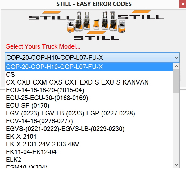
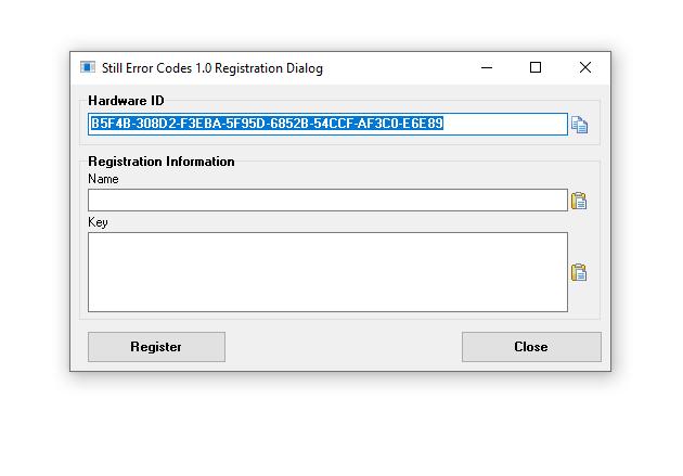
1/ Still Forklift Easy Error Codes
2/ This PC Lock Send Me Yours Name + HWID
3/ One Key for one PC
4/ After install Comment on below «Yours Name + HWID» or sent to email: «autorepairmanuals.ws@gmail.com»
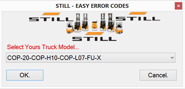
COP-20-COP-H10-COP-L07-FU-X.txt
CS.txt
CX-CXD-CXM-CXS-CXT-EXD-S-EXU-S-KANVAN.txt
ECU-14-16-18-20-(2015-04).txt
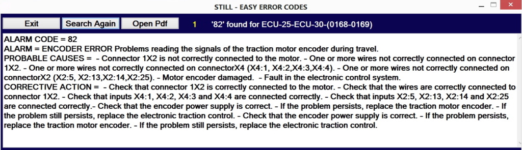
ECU-25-ECU-30-(0168-0169).txt
ECU-SF-(0170).txt
EGV-(0223)-EGV-LB-(0233)-EGP-(0227-0228).txt
EGV-14-16-(0276-0277).txt
EGVS-(0221-0222)-EGVS-LB-(0229-0230).txt
EK-X-2101.txt
EK-X-2101_INFO.txt
EK-X-2131-24V-2133-48V.txt
EK-X-2131-24V-2133-48V_INFO.txt
EK11-04-EK12-04.txt
ELK2.txt
ESM10-(X334).txt
EXD20-EXD-SF20-EXU-SF20-(0283-0284-0179).txt
EXU22.txt
EXV-10-10Basic-12-12i-14-14i.txt
EXV-10-10Basic-12-12i-14-14i_INFO.txt
EXV14-16-20-(i)-EXV-SF14-16-20-(i)-(0323-0334)-EXP-(0301-0303-0305).txt
EXV14-16-20-(i)-EXV-SF14-16-20-(i)-(0323-0334)-EXP-(0301-0303-0305)_INFO.txt
FM-X-(1900-1922).txt
FM-X-(1900-1922)_INFO.txt
FM-X-(1900-1922)_OLD.txt
FM-X-1801.txt
FM-X-1801_INFO.txt
FMI-Typ-429.txt
FMI-Typ-447.txt
FMI-Typ-451.txt
FS-X33.txt
FV-X-12-12i-16-16i.txt
GX-X-GX-Q.txt
GX-X-GX-Q_INFO.txt
iGo-neo-CX-20-(1063).txt
Lithium-ion-technology.txt
MX-X-2332-2334.txt
MX-X-2332-2334_INFO.txt
MX-X-2332-2334_old.txt
MX-X-MX-Q-Generation-1-2-80V.txt
MX-X-MX-Q-Generation-1-2-80V_OLD.txt
MX-X-MX-Q-Generation-3-48V.txt
MX-X-MX-Q-Generation-3-48V_OLD.txt
MX-X-MX-Q-Generation-3-80V.txt
MX-X-MX-Q-Generation-3-80V_OLD.txt
MX-X-MX-Q-Generation-4-48V.txt
MX-X-MX-Q-Generation-4-48V_OLD.txt
MX-X-MX-Q-Generation-4-80V.txt
MX13-3-MX15-3-MX13-3i-MX15-3i.txt
OPX-LTX50.txt
OPX-LTX50_INFO.txt
R07—25-R08-20-2017.txt
R07-25-R08-20.txt
R07-25-R08-20_INFO.txt
R20-2008-2014-2017-2024-2037-2044.txt
R20i-2015-2045-2049.txt
R60-(S60).txt
R60-6022-6029-6042-6052.txt
R60i-6033-6035-6053-6055.txt
R60i-6036-6039.txt
R70.txt
RX20-RX60_INFO.txt
RX20.txt
RX50-5051-5055.txt
RX50-5051-5055_INFO.txt
RX50-5060-5066.txt
RX50-5060-5066_INFO.txt
RX60.txt
RX70.txt
RX70_INFO.txt
SU-SD-SV.txt
X_Not_Sorted_Model_List.txt
X_Sorted_Model_List.txt
Last edited by a moderator: Feb 20, 2020
More the random threads same category:
- STILL STEDS Forklifts 8.17 R2 [02.2017] Full Instruction + Activation
- STILL STEDS 8.16.R2 Plus [05.2016] Full Instruction + Activation
- Still Steds 8.14 FULL
- STILL Some Error Code PDF
- Still Steds Navigator Forklifts 8.19 R2 [02.2019]
- STILL STEDS Forklifts 8.15 R2 [08.2015] Full VM
- Prosecco Multi KG V4 + ProSecCo Activator
- STETI EPC (Steinbock) Forklifts v3.6 2003 Spare Parts Catalog
- STILL STEDS Forklifts 8.18 R3 [03.2018] Full Instruction
- Forklift ProSecCo KG 2015 v2 (Clark,Linde,Lidos,Liebherr,Valtra,Widos,Jeti,Still)
- Still Steds Navigator Forklifts 8.18 R8 [09.2018] Full Instruction
- Still Steds Navigator Forklifts 8.20 R2 [02.2020] Full Instruction
- Forklift ProSecCo KG 2016 v1
- Still Forklift ProSecCo KG 2016v2
- Still Steds Navigator Forklifts 8.19 R8 2020 [08.2019] Full Instruction

Master
Administrator
- Joined
- Sep 3, 2012
- Messages
-
17,463
- Likes
- 709
1/ Still Forklift Easy Error Codes
2/ This PC Lock Send Me Yours Name + HWID
3/ One Key for one PC
4/ After install Comment on below «Yours Name + HWID» or sent to email: «autorepairmanuals.ws@gmail.com»
empilhomat
New Member
- Joined
- Feb 16, 2021
- Messages
-
1
- Likes
- 0
dmis

- Joined
- Oct 29, 2022
- Messages
-
1
- Likes
- 0

Admin
Administrator
- Joined
- Oct 26, 2015
- Messages
-
488
- Likes
- 14
![]()
STILL Forklift Fault Codes
STILL Forklift Fault Codes
STILL Forklift Fault Codes.pdf
Adobe Acrobat Document
2.3 MB
![]()
STILL RX 50 Operator Manual
STILL RX 50 Operator Manual
STILL RX 50 Operator Manual.pdf
Adobe Acrobat Document
7.8 MB
![]()
STILL FM X Operator Manual
STILL FM X Operator Manual
STILL FM X Operator Manual.pdf
Adobe Acrobat Document
5.7 MB
![]()
STILL RX 60 16 18 20 Operator Manual
STILL RX 60 16 18 20 Operator Manual
STEEL RX 60 16 18 20 Operator Manual.pdf
Adobe Acrobat Document
1.2 MB
![]()
STILL RX 20-E3 Operator Manual
SILL RX 20-E3 Operator Manual
STEEL RX 20-E3 Operator Manual.pdf
Adobe Acrobat Document
5.7 MB
![]()
STILL RX 70 16 20 Diesel Operator Manual
STILL RX 70 16 20 Diesel Operator Manual
STEEL RX 70 16 20 Diesel Operator Manual
Adobe Acrobat Document
5.3 MB
![]()
STILL RX 70 20 35 Operator Manual
STILL RX 70 20 35 Operator Manual
STEEL RX 70 20 35 Operator Manual.pdf
Adobe Acrobat Document
5.0 MB
![]()
STILL RX 60 60 80 Operator Manual
STILL RX 60 60 80 Operator Manual
STILL RX 60 60 80 Operator Manual.pdf
Adobe Acrobat Document
4.8 MB
![]()
STILL RX 70 40 50 Operator Manual
STILL RX 70 40 50 Operator Manual
STILL RX 70 40 50 Operator Manual.pdf
Adobe Acrobat Document
6.0 MB
![]()
STILL RX 60 25 35 Operator Manual
STILL RX 60 25 35 Operator Manual
STILL RX 60 25 35 Operator Manual.pdf
Adobe Acrobat Document
6.2 MB
![]()
STILL RX 70 60 80 Operator Manual
STILL RX 70 60 80 Operator Manual
STILL RX 70 60 80 Operator Manual.pdf
Adobe Acrobat Document
5.2 MB
Some STILL Forklift Truck Operator Manuals PDF, Fault Codes DTC are above this page — FM, RX.
STILL GmbH was founded in 1920 in Hamburg and is named after its founder Hans Still. It all started with a small electrical workshop where the electric motors
were repaired and semi-automatic emergency power supply units were manufactured.
After a considerable period of time, including the WW2, in 1949, Still presented his first loader. From that moment a new history of the company began — already under the sign of
the manufacturer of forklifts.
Today there are several enterprises in STILL.
The expansion began in 1989, when SAXBY was acquired in 1997 Wagner purchased.
In 2001, the production site in South America began operating. Since 2006, STILL belongs to Kion Group.
In addition to 4 factories, Still has 14 branches in Germany, 20 subsidiaries and an extensive dealer network around the world. The
geography of deliveries of loaders STILL — more than 200 countries of the world.
The company produces forklift electric, diesel and gas forklifts and warehouse stackers. Among the products — forklifts, pickers, lifting carts, tractors, cars and other storage equipment.
STILL not only offers equipment for sale, but also leases it (including used ones). Specialists of the company are engaged in maintenance,
repair and maintenance of leased equipment (forklifts, stackers, etc.), conduct training for the personnel of the client enterprise.
Another innovation from STILL is the development and implementation of software solutions that establish control over internal material
and information flows, combining them into a single chain «Receiving goods — Distribution — Warehousing — Shipping».
FLTA Fork Lift Truck Association, a world association of manufacturers of forklifts, has repeatedly awarded diplomas and prizes to the company’s
products.
-
Page 1
Original instructions Diesel trucks With SCR (Selective Catalytic Reduction) RX70-60 RX70-70 RX70-80 RX70-80/900 7341 7342 7343 7344 57348011800 EN — 11/2018… -
Page 3
• Information on transport, initial commis- sioning and storage of industrial trucks Internet address and QR code The information can be accessed at any time by pasting the address https://m.still.de/vdma in a web browser or by scanning the QR code. 57348011800 EN — 11/2018… -
Page 5: Table Of Contents
Table of contents Foreword Your truck …………2 Description of the truck .
-
Page 6
Table of contents Changes to the overhead guard and roof loads ……33 Warning regarding non-original parts . -
Page 7
Table of contents Operation Testing and activities before daily use ……..72 Visual inspections . -
Page 8
Table of contents Actuating the drive direction switch, fingertip version ……130 Actuating the drive direction switch, mini-console version ….. . 131 Starting to drive . -
Page 9
STILL SafetyLight (variant) …….. -
Page 10
Table of contents Closing the cab door ……….238 Opening the side windows . -
Page 11
Table of contents Transporting the truck ……….300 Transport . -
Page 12
Table of contents Topping up the cooling fluid and checking the coolant concentration ….343 Cleaning the radiator and checking for leaks ……. . 346 Draining water from the fuel filter . -
Page 13: Foreword
Foreword…
-
Page 14: Your Truck
Foreword Your truck Your truck Description of the truck General Counterbalanced trucks in the RX70-60/70/80 series with a load capacity of up to 8.0 t are equipped with an internal combustion/electric drive. The internal combustion/electric drive combines the advantages of an internal combustion engine with the precise control of an electric drive.
-
Page 15
Foreword Your truck brake ensures that the truck remains securely in place when parked. Steering The truck is equipped with a swing axle and has kickback-free hydraulic rear-wheel steer- ing. Stability is guaranteed when cornering thanks to speed limitation based on the steer- ing angle. -
Page 16
Foreword Your truck sumption by up to 10% without impairing per- formance. The truck’s cutting-edge exhaust regeneration system also keeps it well within the thresholds of the currently applicable IIIB EU standard. This is achieved using selective catalytic reduction combined with a diesel par- ticulate filter. -
Page 17: General
Foreword Your truck General The truck described in these operating instruc- tions corresponds to the applicable standards and safety regulations. If the truck is to be operated on public roads, it must conform to the existing national regula- tions for the country in which it is being used. The driving permit must be obtained from the appropriate office.
-
Page 18: Use In The Event Of Frost
Foreword Your truck The applicable European emission require- ments (97/68/EC) state that new engines must have an SCR system. Use in the event of frost AdBlue freezes at temperatures of -11°C and below. If the AdBlue tank and the lines freeze, they will be heated automatically during startup and operation.
-
Page 19: Ec Declaration Of Conformity In Accordance With Machinery Directive
Foreword Your truck EC declaration of conformity in accordance with Machinery Directive Declaration STILL GmbH Berzeliusstraße 10 D-22113 Hamburg Germany We declare that the according to these operating instructions Industrial truck according to these operating instructions Model conforms to the latest version of the Machinery Directive 2006/42/EC.
-
Page 20: Accessories
Foreword Your truck Accessories • Key for key switch (two pieces) • Key for cab (variant) • Hexagon socket wrench for emergency lowering 57348011800 EN — 11/2018…
-
Page 21
Foreword Your truck 57348011800 EN — 11/2018… -
Page 22: Labelling Points
Foreword Your truck Labelling points Overview of the front of the truck and the left-hand side of the truck DANGER DANGER STILL GmbH Hamburg Regelmäßige Prüfung (FEM 4.004) nach nationalen Vorschriften basierend auf den EG-Richtlinien: 2009/104/EG, 99/92/EG Nächste Prüfung 10 bar DANGER Die Prüfplakette ersetzt nicht das Prüfprotokoll…
-
Page 23
Foreword Your truck Decal information: Caution/Read the op- Warning sign: Do not stand underneath the erating instructions/Fasten seat belt/Apply fork/Do not stand on the fork parking brake when leaving the truck/Pas- Decal information: StVZO (German Road sengers are not allowed/Do not jump off if Traffic Licensing Regulations) information the truck is tipping over/Lean in the opposite (variant) -
Page 24
Foreword Your truck Overview of the rear of the truck and the right-hand side of the truck DANGER DANGER 10 bar 57348011800 EN — 11/2018… -
Page 25: Nameplate
Foreword Your truck Decal information: Parking brake released Decal information: 12-V socket Decal information: Parking brake applied Decal information: Diesel fuel Decal information: Lifting gear attachment Decal information: Tyre filling pressure point (variant) Manufacturer’s label text Decal information: To unlock, turn 90° to the Decal information: Caution / Read the right/to lock, turn 90°…
-
Page 26: Production Number
Foreword Using the truck Production number xx xxxx x xxxxx NOTE The production number is used to identify the truck. It can be found on the nameplate and must be referred to in all technical questions. The production number contains the following coded information: (1) Production location (2) Model…
-
Page 27: Proper Use During Towing
Foreword Using the truck The truck may only be used for its proper purpose as set out and described in these operating instructions. If the truck is to be used for purposes other than those specified in the operating instruc- tions, the approval of the manufacturer and, if applicable, the relevant regulatory authorities must be obtained beforehand to prevent haz-…
-
Page 28: Place Of Use
Foreword Using the truck The truck may not be operated in areas where there is a risk of fire, explosion or corrosion, or in areas that are particularly dusty. Stacking or unstacking is not permissible on inclined surfaces or ramps. Place of use The truck can be used outdoors.
-
Page 29: Using Working Platforms
Foreword Using the truck NOTE Please note the definition of «operating com- pany» in the sense of responsible persons! DANGER Risk to health from exhaust gases! Exhaust gases from internal combustion engines are harmful to your health. In particular, the soot particles contained in the diesel exhaust gas can cause cancer.
-
Page 30: Information About The Documentation
Foreword Information about the documentation Information about the documentation Documentation scope • Original operating instructions • Original operating instructions for attach- ments (variant) • Spare parts list • Depending on the truck equipment, «UPA» operating instructions may also be provided NOTE Refer to the additional information in the section entitled «Rules for the operating…
-
Page 31: Supplementary Documentation
Foreword Information about the documentation The personnel responsible for operating and maintaining the equipment must be familiar with these operating instructions. The operating company must ensure that all users have received, read and understood these operating instructions. Safely store the complete documentation and pass on to the subsequent operating company when transferring or selling the truck.
-
Page 32: Issue Date And Topicality Of The Operating Instructions
The issue date of these operating instructions can be found on the title page. STILL is constantly engaged in the further development of trucks. These operating instructions are subject to change, and any claims based on the information and/or illustrations contained in them cannot be asserted.
-
Page 33: List Of Abbreviations
Foreword Information about the documentation NOTE For technical requirements that require special attention. ENVIRONMENT NOTE To prevent environmental damage. List of abbreviations NOTE This list of abbreviations applies to all types of operating instructions. Not all of the abbre- viations that are listed here will necessarily appear in these operating instructions.
-
Page 34
Foreword Information about the documentation Abbrevi- Meaning Explanation ation German authority for monitoring/issuing regulations for worker protection, environ- Gewerbeaufsichtsamt mental protection, and consumer protec- tion Transfer of data packets in wireless GPRS General Packet Radio Service networks ID no. ID number International Organization for Standard- International standardisation organisation ization… -
Page 35: Definition Of Directions
Foreword Information about the documentation Definition of directions The directions «forwards» (1), «backwards» (3), «right» (2) and «left» (4) refer to the installation position of the parts as seen from the driver’s compartment; the load is to the front. 6210_001-031 Schematic views View of functions and operations This documentation explains the (usually…
-
Page 36
Foreword Information about the documentation View of the display operating unit NOTE Views of operating statuses and values in the display of the display operating unit are examples and partly dependent on the truck equipment. As a result, the displays shown of the actual operating statuses and values can vary. -
Page 37: Environmental Considerations
Foreword Environmental considerations Environmental considerations Packaging During delivery of the truck, certain parts are packaged to provide protection during transport. This packaging must be removed completely prior to initial start-up. ENVIRONMENT NOTE The packaging material must be disposed of properly after delivery of the truck. Disposal of components and batteries The truck is composed of different materials.
-
Page 38
Foreword Environmental considerations 57348011800 EN — 11/2018… -
Page 39: Safety
Safety…
-
Page 40: Definition Of Responsible Persons
Safety Definition of responsible persons Definition of responsible persons Operating company The operating company is the natural or legal person or group who operates the truck or on whose authority the truck is used. The operating company must ensure that the truck is only used for its proper purpose and in compliance with the safety regulations set out in these operating instructions.
-
Page 41: Drivers
Safety Definition of responsible persons regarding the industrial truck to be tested and the risk being assessed Drivers This truck may only be driven by suitable per- sons who are at least 18 years of age, have been trained in driving, have demonstrated their skills in driving and handling loads to the operating company or an authorised rep- resentative, and have been specifically in-…
-
Page 42
Safety Definition of responsible persons DANGER The use of drugs, alcohol or medications that affect reactions impair the ability to drive the truck! Individuals under the influence of the aforementio- ned substances are not permitted to perform work of any kind on or with the truck. Prohibition of use by unauthorised persons The driver is responsible for the truck during… -
Page 43: Basic Principles For Safe Operation
Safety Basic principles for safe operation Basic principles for safe operation Insurance cover on company premises In many cases, company premises are restricted public traffic areas. NOTE The business liability insurance should be reviewed to ensure that, in the event of any damage caused in restricted public traffic areas, there is insurance cover for the truck in respect of third parties.
-
Page 44
DANGER Risk of injury if the truck tips over! Even if an approved restraint system is in use, there is still a residual risk that the driver could be injured if the truck tips over. The risk of injury can… -
Page 45: Changes To The Overhead Guard And Roof Loads
Original parts, attachments and accessories are specially designed for this truck. We specifically draw your attention to the fact that parts, attachments and accessories supplied by other companies have not been tested and approved by STILL. 57348011800 EN — 11/2018…
-
Page 46: Damage, Defects And Misuse Of Safety Systems
Safety Basic principles for safe operation CAUTION Installation and/or use of such products may there- fore have a negative impact on the design features of the truck and thus impair active and/or passive driving safety. We recommend that you obtain approval from the manufacturer and, if necessary, from the relevant regulatory authorities before installing such parts.
-
Page 47
Safety Basic principles for safe operation The following factors can lead to a loss of stability and are therefore prohibited: • Different tyres on the same axle, e.g. pneumatic tyres and superelastic tyres • Tyres not approved by the manufacturer •… -
Page 48: Medical Equipment
Safety Basic principles for safe operation Medical equipment WARNING Electromagnetic interference may occur on medical devices! Only use equipment that is sufficiently protected against electromagnetic interference. Medical equipment, such as pacemakers or hearing aids, may not work properly when the truck is in operation.
-
Page 49: Length Of The Fork Arms
Safety Basic principles for safe operation Length of the fork arms DANGER Risk of accident due to the incorrect selection of fork arms! – The fork arms must match the depth of the load. If the fork arms are too short, the load may fall off the arms after it has been picked up.
-
Page 50: Residual Risk
Safety Residual risk Residual risk Residual dangers, residual risks Despite careful working and compliance with standards and regulations, the occurrence of other risks when using the truck cannot be entirely excluded. The truck and all other system components comply with current safety requirements. Nevertheless, even when the truck is used for its proper purpose and all instructions are followed, some residual risk cannot be…
-
Page 51: Special Risks Associated With Using The Truck And Attachments
Safety Residual risk The manufacturer is not held responsible for accidents involving the truck caused by the failure of the operating company to comply with these regulations either intentionally or carelessly. Stability The stability of the truck has been tested to the latest technological standards and is guaran- teed provided that the truck is used properly and according to its intended purpose.
-
Page 52
Safety Residual risk time the truck is used in a manner that falls outside the scope of normal use, and in cases where the driver is not certain that he can use the truck correctly and without the risk of acci- dents. -
Page 53
Safety Residual risk 57348011800 EN — 11/2018… -
Page 54: Overview Of Hazards And Countermeasures
Safety Residual risk Overview of hazards and counter- measures NOTE This table is intended to help evaluate the hazards in your facility and applies to all drive types. It does not claim to be complete. – Observe the national regulations for the country in which the truck is being used.
-
Page 55
Safety Residual risk Hazard Measure Check note Notes √ Complete — Not applicable Impermissible usage Issuing of operating German Ordinance on (improper usage) instructions Industrial Safety and Health (BetrSichV) and German Health and labour protection law (ArbSchG) Written notice of German Ordinance on instruction to driver Industrial Safety and… -
Page 56
Safety Residual risk Hazard Measure Check note Notes √ Complete — Not applicable When charging the Note the German Association for traction battery Ordinance on Electrical, Electronic Industrial Safety and and Information Health (BetrSichV), Technologies (VDE) the operating regulation 0510: In instructions and the particular German Engineering… -
Page 57: Danger To Employees
Safety Residual risk Danger to employees According to the German Ordinance on Indus- trial Safety and Health (BetrSichV) and labour protection law (ArbSchG), the operating com- pany must determine and assess hazards during operation, and establish the labour protection measures required for employ- ees (BetrSichVO).
-
Page 58: Safety Tests
Safety Safety tests Safety tests Regular safety inspection of the truck Safety inspection based on time and extraordinary incidents The operating company must ensure that the truck is checked by a specialist at least once a year or after particular incidents. As part of this inspection, a complete check of the technical condition of the truck must be performed with regard to accident safety.
-
Page 59: Particle Filter
Safety Safety tests NOTE Observe the national regulations for the country in which the truck is being used. Particle filter The truck has an SCR (Selective Catalytic Reduction) exhaust gas treatment system as part of its standard equipment. The truck may be operated in entirely or partially enclosed working areas.
-
Page 60: Insulation Testing
Safety Safety tests • Employees must be made aware of dangers and protective measures • The particle filter must be replaced every 6000 operating hours. The exhaust-gas check must be carried out by a competent person (see the chapter entitled «Definition of terms used for responsible persons») and the results must be recorded in writing NOTE…
-
Page 61: Safety Regulations For Handling Consumables
Safety Safety regulations for handling consumables Safety regulations for handling consumables Permissible consumables DANGER Failure to observe the safety regulations relating to consumables may result in a risk of injury, death or damage to the environment. – Observe the safety regulations when handling such materials.
-
Page 62: Hydraulic Fluid
Safety Safety regulations for handling consumables WARNING Prolonged intensive contact with the skin can result in dryness and irritate the skin! – Avoid contact and consumption. – Wear protective gloves. – After any contact, wash the skin with soap and water, and then apply a skin care product.
-
Page 63: Battery Acid
Safety Safety regulations for handling consumables WARNING These fluids are pressurised during operation of the truck and are hazar- dous to your health. – Do not allow the fluids to come into contact with the skin. – Avoid inhaling spray. –…
-
Page 64: Diesel Fuel
Safety Safety regulations for handling consumables WARNING Battery acid contains dissolved sulphuric acid. This is corrosive. – When working with battery acid, use appropriate PSA (rubber gloves, apron, protection goggles). – When working with battery acid, never wear a watch or jewellery. –…
-
Page 65
Safety Safety regulations for handling consumables WARNING Prolonged intensive contact with the skin can result in loss of skin oils and can irritate the skin! – Avoid contact and swallowing. – Wear protective gloves. – After any contact, wash the skin with soap and water, and then apply a skin care product. -
Page 66: Coolant And Cooling Fluid
Safety Safety regulations for handling consumables Coolant and cooling fluid WARNING Coolant and cooling fluid can be hazardous to your health and the environment! Coolants are chemical corrosion inhi- bitors and cooling system protecting agents such as Glysantin. The coo- ling fluid is an appropriate mixture of water and coolant.
-
Page 67
Safety Safety regulations for handling consumables – Neutralise any spilt battery acid immedi- ately. – Always observe national regulations con- cerning the disposal of used oil. 57348011800 EN — 11/2018… -
Page 68: Emissions
Safety Emissions Emissions The values specified apply to a standard truck (compare the specifications in the «Technical data» chapter). Different tyres, lift masts, additional units etc. may produce different values. Noise emissions The values were determined based on measuring procedures from the standard EN 12053 «Safety of industrial trucks.
-
Page 69
Safety Emissions Vibrations The vibrations of the machine have been determined on an identical machine in ac- cordance with the standards DIN EN 13059 «Safety of industrial trucks — Test methods for measuring vibration» and DIN EN 12096 «Mechanical vibration — Declaration and verifi- cation of vibration emission values». -
Page 70
Safety Emissions Exhaust gases DANGER Risk to health from exhaust gases! Exhaust gases from internal combustion engines are harmful to your health. In particular, the soot particles contained in the diesel exhaust gas can cause cancer. When the internal combustion engine is running, there is a risk of poisoning from the CO, CH and NOx components contained in the exhaust gas. -
Page 71: Overviews
Overviews…
-
Page 72: Overview
Overviews Overview Overview Left-hand side (when viewed in the drive direction) 7341_003-002_V3 Lift mast Drive axle Driver’s compartment Tilt cylinder Overhead guard Fork arms Bonnet Fork carriage Battery maintenance lid Lift cylinder Steering axle 57348011800 EN — 11/2018…
-
Page 73
Overviews Overview Right-hand side (when viewed in the drive direction) Fresh air filter for heating system Right-hand service flap AdBlue filler neck Coupling pin Tank filler neck Pre-cleaner 57348011800 EN — 11/2018… -
Page 74: Driver’s Compartment
Overviews Driver’s compartment Driver’s compartment Parking brake lever Bottle holder for bottles of max. 0.5 l Steering wheel Driver’s seat Key switch Storage compartment / storage compart- Display and operating unit ment with cover (variant) Document holder / storage compartment for Compartment operating instructions Filler cap for windscreen washer reservoir…
-
Page 75: Operating Devices And Display Elements
Overviews Operating devices and display elements Operating devices and display elements Display and operating unit Hazard warning system button Operating hours display Front windscreen wiper button Time display (digital) Working spotlight button Particle filter display Drive programme selector button Rotating beacon display Softkey Lighting Interior lighting display Lighting symbol…
-
Page 76: Operating Devices For Hydraulic And Driving Functions
Overviews Operating devices and display elements – If you have any questions, please contact your authorised service centre. Operating devices for hydraulic and driving functions Different versions of the operating devices are available for operating the truck’s hydraulic and traction functions. The truck can be equipped with the following operating devices: •…
-
Page 77: Double Mini-Lever
Overviews Operating devices and display elements Double mini-lever «Lift mast» 360° lever Function key «F1» Function key «F2» «Drive direction/turn indicator» cross lever Function key «5th function» «Attachments» cross lever Signal horn button NOTE Depending on the specification, various electric attachment parts can be controlled via function keys (2) and (3).
-
Page 78: Three-Way Mini-Lever
Overviews Operating devices and display elements Three-way mini-lever 7325_003-026 «Lift mast» 360° lever Function key «5th function» Function key «F1» «Auxiliary hydraulics 1» operating lever Function key «F2» «Auxiliary hydraulics 2» operating lever «Drive direction/turn indicator» cross lever Signal horn button NOTE Depending on the specification, various electric attachment parts can be controlled…
-
Page 79: Four-Way Mini-Lever
Overviews Operating devices and display elements Four-way mini-lever 7325_003-027 «Lift/lower» operating lever Function key «5th function» «Tilt» operating lever «Auxiliary hydraulics 1» operating lever Function key «F1» «Auxiliary hydraulics 2» operating lever Function key «F2» Signal horn button «Drive direction/turn indicator» cross lever NOTE Depending on the specification, various electric attachment parts can be controlled…
-
Page 80: Joystick 4Plus
Overviews Operating devices and display elements Joystick 4Plus 6210_003-087 Horizontal rocker button for «3rd hydraulic LED for clamp locking mechanism (variant) function», tilt the lift mast Slider for the «4th hydraulic function», e.g. Pictograms for the basic hydraulic functions reach frame forwards/backwards Pictograms for the 5th hydraulic function and Vertical rocker button for the «drive direction»…
-
Page 81: Fingertip
Overviews Operating devices and display elements Fingertip 7325_003-028 Function key «F1» «Attachments» operating lever Function key «F2» «Attachments» operating lever Left turn indicator button «Tilt» operating lever Signal horn button «Lift/lower» operating lever Right turn indicator button Drive direction switch Function key «5th function»…
-
Page 82: Mini Console
Overviews Operating devices and display elements Mini console The mini console is located on the steering column below the steering wheel. 7311_003-056 Travel direction switch Direction indicator switch 57348011800 EN — 11/2018…
-
Page 83: Operation
Operation…
-
Page 84: Testing And Activities Before Daily Use
Operation Testing and activities before daily use Testing and activities before daily use Visual inspections WARNING Risk of injury from falling off the truck! When climbing onto the truck, there is a risk of getting stuck or slipping and falling. Use suitable equipment to reach higher points on the truck.
-
Page 85
Operation Testing and activities before daily use Component Course of action Check the area under the forklift truck for leaking Underside consumables. Perform a visual inspection for integrity. Overhead guard, guard grille (variant) Check for secure mounting. Make sure they are clean (free of ice, not slippery). Steps Perform a visual inspection for integrity. -
Page 86
Operation Testing and activities before daily use Component Course of action Perform a visual inspection for wear and damage. Make sure that only rims of the same type from the same manufacturer are fitted. Wheels, tyres In the event of uneven tyre wear, replace both tyres. Observe the safety regulations in the section entitled «Tyres». -
Page 87: Climbing Into And Out Of The Truck
Operation Testing and activities before daily use Climbing into and out of the truck WARNING Risk of injury when climbing into and out of the truck due to slipping, striking parts of the truck or becoming stuck! If the footwell cover is very dirty or smeared with oil, there is a risk of slipping.
-
Page 88
Operation Testing and activities before daily use Climbing in and out of trucks featuring a single wheel and two steps When climbing into and out of the truck, use the handles (2) and (4) for support. The overhead guard post (1) can also be used for support. -
Page 89
Operation Testing and activities before daily use Climbing in and out of trucks featuring two wheels and three steps When climbing into and out of the truck, use the handles (2) and (4) for support. The overhead guard post (1) can also be used for support. -
Page 90: Shelves And Cup Holders
Operation Testing and activities before daily use Shelves and cup holders WARNING Risk of accident! Objects that fall into the footwell during travel as a result of steering or braking may slip between the pedals (3) and prevent them from working correctly. It may then be impossible to brake the truck.
-
Page 91
Operation Testing and activities before daily use WARNING To obtain optimum seat cushioning, you must ad- just the seat suspension to your own body weight. This is better for your back and protects your health. – To prevent injury, make sure that there are no objects within the swivel area of the seat Moving the driver’s seat –… -
Page 92
Operation Testing and activities before daily use Adjusting the seat suspension NOTE The driver’s seat can be adjusted to suit the weight of the individual driver. In order to achieve the best seat suspension setting, the driver should perform the adjustment whilst sitting in the seat. -
Page 93
Operation Testing and activities before daily use Adjusting the lumbar support (variant) NOTE The lumbar support can be adjusted to suit the contours of the individual driver’s spine. Adjusting the lumbar support moves a convex support cushion into the upper or lower part of the backrest. -
Page 94: Adjusting The Armrest
Operation Testing and activities before daily use Switching the seat heater (variant) on and off NOTE The seat heater only functions if the seat contact switch is active, i.e. when the driver is sitting on the driver’s seat. – Switch the seat heater (7) on or off using the switch.
-
Page 95: Adjusting The Steering Column
Operation Testing and activities before daily use Adjusting the length of the armrest – Release the star-grip handle (1) by turning it anti-clockwise. – Shift the armrest (2) into the desired posi- tion. – Tighten the star-grip handle by turning it clockwise.
-
Page 96: Unlocking The Emergency Off Switch
Operation Testing and activities before daily use Unlocking the emergency off switch NOTE Only trucks with a joystick 4Plus (variant) have an emergency off switch. – Pull out the emergency off switch (1) until it unlatches. 6321_003-142 Operating the signal horn –…
-
Page 97: Seat Belt
Operation Testing and activities before daily use Seat belt DANGER Even when using an approved restraint system, there is some residual risk that the driver might be injured if the truck tips over. This risk of injury can be reduced through the combined use of the restraint system and the seat belt.
-
Page 98
Operation Testing and activities before daily use – Pull the seat belt (3) out of the belt retractor without jerking and fasten closely around the body over the thighs. NOTE Sit as far back as possible so that your back is leaning against the seat backrest. -
Page 99
Operation Testing and activities before daily use Releasing the seat belt – Push the red button (4) on the buckle (1). – Manually guide the belt tongue slowly back to the retractor. NOTE Do not allow the seat belt to retract too quickly. The automatic blocking mechanism may be triggered if the belt tongue strikes the housing. -
Page 100: Using The Driver’s Cab
Operation Testing and activities before daily use Using the driver’s cab DANGER Risk of fatal injury in the event of falling from the truck if it tips over! In order to prevent the driver from sliding under- neath the truck and being crushed if the truck tips over, a restraint system must be in place and must be used.
-
Page 101
Operation Testing and activities before daily use Checking the service brake – Release the parking brake. – Depress the brake pedal (1). There must be a slight pedal clearance and then a noticeable pressure point at the brake. – Accelerate the unladen truck in a clear area. –… -
Page 102
Operation Testing and activities before daily use WARNING There is no electrical braking assistance when the key switch is switched off! Switching off the key switch will de-energise the entire electrical system. The regenerative brake will not be available. CAUTION There is no power steering when the key switch is switched off! The truck is equipped with hydraulic power stee-… -
Page 103: Checking The Steering System For Correct Function
Operation Testing and activities before daily use Checking the steering system for correct function DANGER If the hydraulics fail, there is a risk of accident as the steering characteristics have changed. – Do not operate the truck if it has a defective steering system.
-
Page 104: Zero Adjustment Of The Load Measurement (Variant)
Operation Testing and activities before daily use CAUTION There is no power steering when the emergency off switch is actuated! The truck is equipped with a hydraulic power stee- ring system. When the emergency off switch is actuated, the hydraulic system is completely shut down.
-
Page 105
Operation Testing and activities before daily use NOTE Accurate zero adjustment is only possible within the first lifting stage of the lift mast. When carrying out the zero adjustment, do not raise the fork more than 800 mm above the ground. -
Page 106: Checking The Vertical Lift Mast Position (Variant) For Correct Function
Operation Switching on and starting Checking the vertical lift mast position (variant) for correct function NOTE The function check of the lift mast vertical position (variant) must be carried out every time a truck is commissioned. – Press the Softkey (1).
-
Page 107
Operation Switching on and starting a straight line. To do this, rotate the steering wheel by approximately half a turn. – Insert the switch key (1) into the key switch and turn to position «I». 5060_003-029_V2 This initiates a self-test. All lamps in the drive direction and turn indicator displays light up briefly. -
Page 108
Operation Switching on and starting When the key switch is switched on, the display shows the welcome screen. The truck controller is now fully started up. If the truck is equipped with the «access authorisation with PIN code» variant, the display initially changes to the input menu for access authorisation. -
Page 109: Access Authorisation With Pin Code (Variant)
Operation Switching on and starting CAUTION Lack of fuel can cause malfunctions! If the fuel tank has been run empty, the fuel injection system can draw in air bubbles. This can lead to malfunctions in the fuel injection system. When the fuel tank is replaced during repair work or because it has been run empty, diesel fuel must be pre-pumped with the fuel hand pump after filling, see the «Using the fuel hand pump»…
-
Page 110
The driver PINs are stored in the truck control unit. These are still available if the display and operating unit has been changed. The authorised service centre can use a diagnostic device to read out the driver PIN and, if necessary, restore the factory default driver PIN. -
Page 111
Operation Switching on and starting ACCESS CODE input menu The driver enters the five-digit driver PIN (00000 to 99999) in this input menu. The driver PIN is entered using the buttons or Softkeys (1). The digits entered for the driver PIN (2) are not visible but are represented by circles instead. -
Page 112
Operation Switching on and starting After three invalid entry attempts, the mes- sage appears. The input is CODE DENIED then locked for five minutes before another attempt can be made. BQ_024_en_V2 Defining the driver PIN NOTE The driver PINs can be defined only by per- sons with the appropriate access authorisa- tion, e.g. -
Page 113
Operation Switching on and starting appears in the display. PASSWORD – Enter the four-digit password (factory default: 2777) using the buttons (1). – Confirm the input using Softkey (2). BQ_030_en_V2 appears in the display. CONFIGURATION – Use the drive program selection button (1) and the menu change button (3) to select menu. -
Page 114
Operation Switching on and starting Selecting the driver PIN In the menu, there are fifty ACCESS CODE possible driver PINs to choose from. The digit sequences can be set or changed in submenu. NEW CODE Once the menu has been ac- ACCESS CODE cessed, the selection field (2) contains… -
Page 115
Operation Switching on and starting appears in the display. CONFIRM submenu is used to confirm CONFIRM the new driver PIN. – Enter the new driver PIN for a second time in the field (8) using the buttons CONFIRM or Softkeys (7). If the entry matches the new driver PIN previously entered, the system will accept the new driver PIN once the last digit has… -
Page 116
Operation Switching on and starting After three incorrect entries, the CODE DE- message appears. NIED The display switches back to the ACCESS menu. The desired driver PIN must be CODE re-defined. BQ_024_en_V2 Changing the password It is recommended that you change the factory default password. -
Page 117
Operation Switching on and starting appears in the display. PASSWORD – Enter the current password using the buttons (1). – Confirm the input using Softkey (2). BQ_030_en_V2 appears in the display. CONFIGURATION – Use the drive program selection button (1) and the menu change button (3) to select menu. -
Page 118
Operation Switching on and starting appears in PASSWORD/PASSWORD LEVEL the display. – Use the drive program selection button (1) and the menu change button (4) to select the desired (2). PASSWORD LEVEL – Confirm your selection using Soft- (3). BQ_033_en appears in the display. -
Page 119: Starting The Engine
Operation Switching on and starting Starting the engine DANGER Risk to health from exhaust gases! Exhaust gases from internal combustion engines are harmful to your health. In particular, the soot particles contained in the diesel exhaust gas can cause cancer. When the internal combustion engine is running, there is a risk of poisoning from the CO, CH and NOx components contained in the exhaust gas.
-
Page 120
Operation Switching on and starting NOTE If the engine does not start due to a discharged battery, it can be jump-started. NOTE If the truck is left turned off for a lengthy period in ambient temperatures below -5°C, the truck will need to pre-heat at the next start-up. -
Page 121: Operating The Display And Operating Unit
Operation Operating the display and operating unit Operating the display and operating unit Displays Standard display elements In the factory setting, the following indicators can be seen in the display and operating unit: Fuel level Shows the fuel level in the fuel tank in %. Drive programme Displays the current drive programme numerically (1-5).
-
Page 122: Adjusting The Displays
Operation Operating the display and operating unit Adjusting the displays NOTE The parking brake must always be engaged when you adjust the displays. The displays cannot be adjusted if the parking brake is not engaged. NOTE When adjusting the displays, do not actuate the hydraulic system operating devices.
-
Page 123: Symbols In The Display
Operation Operating the display and operating unit The display changes to the menu. PASSWORD NOTE It may be necessary to enter a password in order to configure the displays. This depends on the configuration of the display-operating unit. For configuration of the display-operating •…
-
Page 124
Operation Operating the display and operating unit Description Symbol Service required Lift limitation Reference cycle Battery charging Drive program Hour meter Odometer Daily hour meter Daily odometer Speed Steering angle Load Time Hydraulic system Exh.gas purifier Coolant temperature Fuel level Blue-Q Power rating (average) Power rating (trend) -
Page 125
Operation Operating the display and operating unit Symbols for error messages Description Symbol Brake system malfunction Overheating of the engine Overheating Malfunction in the electrical system General malfunction Symbols for softkey functions of auxiliary equipment The following symbols for softkey functions are used on the left of the display for auxiliary equipment: Description… -
Page 126
Operation Operating the display and operating unit Description Symbol Seat heater OFF Seat heater ON Signal horn OFF Signal horn ON Cruise control OFF Cruise control ON Automatic mast vertical positioning OFF Automatic mast vertical positioning ON Load measurement zero adjustment OFF Load measurement zero adjustment ON Load measurement OFF Load measurement ON… -
Page 127
Operation Operating the display and operating unit Status LEDs of the function keys for additional electrical installations The current switch status of a button is indi- cated with LEDs next to the relevant function key for the additional electrical installation. Description Function off LED OFF… -
Page 128: Setting The Date Or Time
Operation Operating the display and operating unit Screen for entering the driver PIN (access code): BQ_038 Setting the date or time – Switch to the menu; CONFIGURATION see the chapter entitled «Adjusting the displays». – Press the Drive programme button (1) or the Menu change button (2) repeatedly until option appears.
-
Page 129: Resetting The Daily Kilometres And Daily Operating Hours
Operation Operating the display and operating unit Resetting the daily kilometres and daily operating hours 1 2 3 4 The daily number of kilometres and daily operating hours displays can be reset to zero: – Switch to the menu; CONFIGURATION see the chapter entitled «Adjusting the displays».
-
Page 130: Softkeys For Operating Various Equipment Variants
Operation Operating the display and operating unit – Use the Softkey (3) to exit the menu and return to the next level up. Softkeys for operating various equipment variants Additional functions can be displayed on the display-operating unit. These additional functions, e.g.
-
Page 131
Operation Operating the display and operating unit STANDARD • Blue-Q is turned off whenever the truck is commissioned. The driver can use the Blue-Q button to switch efficiency mode on and off at any time while the truck is being operated FIXED •… -
Page 132: Blue-Q Efficiency Mode
Operation Blue-Q efficiency mode Blue-Q efficiency mode Functional description The Blue-Q efficiency mode affects both the drive unit and the activation of the additional consumers, and reduces the truck’s energy consumption. If the efficiency mode has been activated, the acceleration behaviour of the truck changes to make acceleration more moderate.
-
Page 133: Switching Off Additional Consumers
Operation Blue-Q efficiency mode Switching off additional consumers If the Blue-Q efficiency mode is activated, the controller switches off various additional consumers after a few seconds in certain con- ditions. The additional consumers available depend on the truck equipment. The following table shows the conditions that cause addi- tional consumers to be switched off.
-
Page 134
Operation Blue-Q efficiency mode configuring the Blue-Q operating modes, see the «Configuring Blue-Q efficiency mode» sec- tion. – Press the Blue-Q button (2) to switch on Blue-Q. The Blue-Q symbol (1) is displayed. The LED (3) illuminates in blue. Blue-Q efficiency mode is switched on. -
Page 135: Driving
Operation Driving Driving Safety regulations when driving Driving conduct The driver must follow the public rules of the road when driving in company traffic. The speed must be appropriate to the local conditions. For example, the driver must drive slowly around corners, in tight passageways, when driving through swing-doors, at blind spots, or on uneven surfaces.
-
Page 136
There is a risk of accident! – Do not use devices during travel or when hand- ling loads. – Set the volume so that warning signals can still be heard. WARNING In areas where use of mobile phones is prohibited, use of a mobile phone or radio telephone is not permitted. -
Page 137: Roadways
Operation Driving Roadways Dimensions of roadways and aisle widths The following dimensions and aisle width requirements apply under the specified conditions to ensure safe manoeuvring. In each case, it must be checked whether a larger aisle width is necessary, e.g. in the case of different load dimensions.
-
Page 138
Operation Driving Maximum gradient [%] Type Model with load Without load RX70-60 7341 RX70-70 7342 RX70-80 7343 RX70-80 7344 (LSP 900) The stated values are used only to compare performance of trucks in the same category. The gradient values in no way represent the normal daily operating conditions. -
Page 139: Setting The Drive Programme
Operation Driving Drainage channels, level crossings and similar objects must be compensated for, and if necessary, ramps must be provided so that trucks can drive over these with as few bumps as possible. Ensure sufficient load capacity of manholes, drain covers and the like. There must be sufficient distance between the highest points of the truck or the load and the fixed elements of the surrounding area.
-
Page 140: Selecting The Drive Direction
Operation Driving – Push the drive programme button (1) repeatedly until the number of the required drive programme appears on the display (2). Drive programmes 1–5 are available. Essentially, the higher the number of the drive programme, the greater the driving dynamics. The following drive programmes are available: 6311_003-028_V2 Drive programme…
-
Page 141: Actuating The Drive Direction Switch, Mini-Lever Version
Operation Driving then decelerated and accelerated again in the opposite direction (reversing). The indicator for the selected drive direction («forwards» (1) or «reverse» (2)) lights up on the display and operating unit. Neutral position If the truck is stopped for an extended period, select the neutral position to prevent the truck from suddenly starting if the accelerator pedal is inadvertently pressed.
-
Page 142: Actuating The Vertical Rocker Switch For The «Drive Direction», Joystick 4Plus Version
Operation Driving Actuating the vertical rocker switch for the «drive direction», joy- stick 4Plus version – For the «forwards» drive direction, push the vertical rocker button for the «drive direction»(1) upwards (A). – For the «reverse» drive direction, push the vertical rocker button for the «drive direction»(1) downwards (B).
-
Page 143: Actuating The Drive Direction Switch, Mini-Console Version
Operation Driving Actuating the drive direction switch, mini-console version – For the «forwards» drive direction, push the drive direction switch (1) forwards. – For the «backwards» drive direction, push the drive direction switch to the rear. NOTE Alternatively, the drive direction can also be selected using the drive direction switches on the operating devices.
-
Page 144
Operation Driving The indicator for the selected drive direction («forwards» (1) or «backwards» (2)) lights up on the display and operating unit. NOTE Depending on the equipment, an acoustic signal (variant) may sound a warning during reverse travel, the warning light (variant) may light up or the hazard warning system (variant) may flash. -
Page 145: Starting Drive Mode, Dual Pedal Version (Variant)
If the truck still cannot be operated, park the truck securely and contact your authorised service centre.
-
Page 146
Operation Driving – Actuate the right-hand accelerator pedal (1) to drive «forward» and actuate the left-hand accelerator pedal (2) to drive «backward». NOTE In the dual pedal version, the drive direction switches on the operating devices do not function. 5060_003-085 The indicator for the selected drive direction («forwards»… -
Page 147
If the truck still cannot be operated, park the truck securely and contact your authorised service centre. -
Page 148: Operating The Service Brake
Operation Driving Operating the service brake The electric brake converts the acceleration energy of the truck into electrical energy. This causes the truck to decelerate. In addition, the truck can be braked using the service brake: – Press the brake pedal (2). In the first section of the brake pedal’s travel, only the regenerative braking takes effect.
-
Page 149: Parking Brake
Operation Driving Zero braking (variant) DANGER Risk of accident! Trucks with zero braking (variant) are not braked when the accelerator pedal is released. – Bring the truck to a standstill by actuating the brake pedal. If your truck features the zero braking equip- ment variant, the electric brake function is disabled.
-
Page 150
Operation Driving Apply the parking brake – Pull the parking brake lever (1) down fully and release. The parking brake lever swivels back half the distance into the middle position automati- cally. The parking brake is engaged and the wheels are blocked. -
Page 151: Steering
Operation Driving Steering DANGER If the hydraulics fail, there is a risk of accident as the steering characteristics have changed. – Do not operate the truck if it has a defective steering system. – Steer the truck by turning the steering wheel (1) accordingly.
-
Page 152: Reducing Speed When Turning (Curve Speed Control)
DANGER The Curve Speed Control function cannot override the physical limits of stability. Despite this function, there still is a risk of tipping! – Before using this function, familiarise yourself with the change to the driving and steering characteristics of the truck.
-
Page 153: Driving On Ascending And Descending Gradients
Operation Driving Driving on ascending and descend- ing gradients DANGER Danger to life! Driving on ascending and descending gradients carries special dangers! – Always follow the instructions below. – On ascending and descending gradients, the load must be carried facing uphill. –…
-
Page 154: Reducing Speed With A Raised Load (Variant)
Operation Driving Reducing speed with a raised load (variant) This function (variant) reduces the speed of the truck with a raised load. 7321_003-052_en_V2 Automatic shut-off of the internal combustion engine (variant) The truck is equipped with an automatic shut-off function that shuts off the internal combustion engine when certain conditions apply simultaneously after a preset waiting STOP…
-
Page 155: Parking
Operation Parking Parking Parking the truck securely and switching it off DANGER Risk of fatal injury from being run over if the truck rolls away! – The truck must not be parked on a slope. – In emergencies, secure the truck using wedges on the side facing downhill.
-
Page 156: Wheel Chock (Variant)
Operation Parking Wheel chock (variant) The wheel chock (variant) is used to prevent the truck from rolling away on a slope. – Lift handle (2) on the support mounting. – Remove wheel chock (1) from the support mounting. – Push the wheel chock under a front axle wheel on the side facing the downhill slope.
-
Page 157: Lifting
Operation Lifting Lifting Lifting system variants The movement of the fork carriage and the lift mast heavily depends on the following equipment: • The lift mast with which the truck is equipped, see ⇒ Chapter «Types of lift mast», P. 4-150 •…
-
Page 158: Lift Mast Vertical Position (Variant)
Operation Lifting Overriding and reactivating the auto- matic lift cut out If a load needs to be lifted to the truck’s maximum lift height and the automatic lift cut out function is not required, it is possible to override the lift cut out. It is automatically reactivated when the truck is switched off and back on again.
-
Page 159
Operation Lifting CAUTION Risk of damage to property due to the lift mast colliding with racks or other objects! – Before using the «lift mast vertical position» comfort feature, position the truck at a sufficient distance from racks and other objects. The «lift mast vertical position»… -
Page 160
Operation Lifting Automatic approach towards the «lift mast vertical position» – Switch on the «lift mast vertical position» comfort feature via the button (1) on the display and operating unit. – Tilt the lift mast forwards using the corre- sponding operating device. The lift mast stops automatically as soon as the prese- lected setting is reached for the «lift mast vertical position». -
Page 161
Operation Lifting The lift mast is tilted forwards and stops as soon as the vertical position is reached. The arrow above the bar shown on the screen of the display and operating unit represents the «lift mast vertical position». Tilt the lift mast forwards beyond the vertical position: –… -
Page 162: Types Of Lift Mast
Operation Lifting Calibrating the «lift mast vertical position» – Set the lift mast to the required position. – Press and hold the button (1) for the «lift mast vertical position» for at least five seconds. The message » » ? VERTICAL POSITION will appear on the display.
-
Page 163: Malfunctions During Lifting Mode
Operation Lifting Triplex lift mast (variant) During lifting, the inner lift cylinder moves up to free lift (3), and then the outer lift cylinders raise the inner lift mast up to the max. height (2). DANGER Risk of accident due to collision of the lift mast or load with low ceilings or entrances.
-
Page 164: Hydraulic Blocking Function
Operation Lifting Load chains not under tension DANGER Danger caused by a falling load! – Make sure that the chain(s) does (do) not become slack when lowering the load. Slack chains can, for instance, result from: • Resting the fork carriage or the load on the racking.
-
Page 165: Lifting System Operating Devices
Operation Lifting – Sit down on the driver’s seat. All the relevant functions of the working hydraulics will be available again. NOTE If it is not possible to release the block on the hydraulics when the load is raised because of a technical fault, the load must be lowered using the «emergency lowering»…
-
Page 166: Controlling The Lifting System Using A Double Mini-Lever
Operation Lifting Controlling the lifting system using a double mini-lever DANGER Reaching into or climbing between moving parts of the truck (e.g. lift mast, sideshifts, working equipment, load carrying devices etc.) can lead to serious injury or death and is therefore prohibited. –…
-
Page 167: Controlling The Lifting System Using A Triple Mini-Lever
Operation Lifting Controlling the lifting system using a triple mini-lever DANGER Reaching into or climbing between moving parts of the truck (e.g. lift mast, sideshifts, working equipment, load carrying devices etc.) can lead to serious injury or death and is therefore prohibited. –…
-
Page 168: Controlling The Lifting System Using A Quadruple Mini-Lever
Operation Lifting Controlling the lifting system using a quadruple mini-lever DANGER Reaching into or climbing between moving parts of the truck (e.g. lift mast, sideshifts, working equipment, load carrying devices etc.) can lead to serious injury or death and is therefore prohibited. –…
-
Page 169: Controlling The Lifting System Using The Joystick 4Plus
Operation Lifting Controlling the lifting system using the joystick 4Plus DANGER Reaching into or climbing between moving parts of the truck (e.g. lift mast, sideshifts, working equipment, load carrying devices etc.) can lead to serious injury or death and is therefore prohibited. –…
-
Page 170
Operation Lifting Tilting the lift mast To tilt the lift mast forwards: – Tilt the horizontal rocker button (2) to the left (C). To tilt the lift mast backwards: – Tilt the horizontal rocker button (2) to the right (D). 6210_003-090 7312_003-022_V2 Fork-carriage sideshift… -
Page 171: Controlling The Lifting System Using The Fingertip
Operation Lifting Controlling the lifting system using the fingertip DANGER Reaching into or climbing between moving parts of the truck (e.g. lift mast, sideshifts, working equipment, load carrying devices etc.) can lead to serious injury or death and is therefore prohibited. –…
-
Page 172: Changing The Fork Arms
Operation Lifting Changing the fork arms DANGER Risk of fatal injury from being run over if the truck rolls away! – Do not park the truck on a gradient. – Apply the parking brake. – Change the fork arms in a separate, safe location on a level surface.
-
Page 173
Operation Lifting Removal – Select a pallet corresponding to the fork arm size. – Set down the pallet next to the fork carriage on the side chosen for removal. – Lift the fork carriage until the fork arms are approx. 3 cm above the pallet. –… -
Page 174: Fork Extension (Variant)
Operation Lifting ged. Otherwise, correct load measurement cannot be guaranteed. Fork extension (variant) DANGER There is a risk of being run over if the truck rolls away and therefore a danger to life. – Do not park the truck on a slope. –…
-
Page 175
Operation Lifting Attachment DANGER Risk to life from falling load! At least 60% of the length of the fork extension must lie on the fork arm. A maximum 40% overhang over the fork arm end is permissible. The fork extension must also be secured against slipping from the fork arm. -
Page 176: Operation With Reversible Fork Arms (Variant)
Operation Lifting Operation with reversible fork arms (variant) DANGER Risk to life from falling load! Standard fork arms are not structurally designed for reverse operation. If this instruction is not observed, it can lead to material failure and the load falling. –…
-
Page 177
Operation Lifting Reversible fork arms (1) can be used to reach an additional lift height. The reversible fork arms are installed on the fork carriage in the same manner as standard fork arms. Loads may be lifted on and beneath the reversible fork arms. -
Page 178: Handling Loads
Operation Handling loads Handling loads Safety regulations when handing loads The safety regulations for handling loads are shown in the following sections. DANGER There is a risk to life caused by falling loads or if parts of the truck are being lowered. –…
-
Page 179: Before Taking Up Load
Operation Handling loads Before taking up load Load capacity The load capacity indicated for the truck on the capacity rating plate may not be exceeded. The load capacity is influenced by the load centre of gravity and the lift height as well as by the tyres, if applicable.
-
Page 180: Load Measurement (Variant)
Operation Handling loads Example Weight of load to be lifted: 880 kg (3) Load distance from fork back: 500 mm (1) Permitted lift height: 5230 mm (2) WARNING Risk of accident from the truck losing stability! The permissible load of the attachments (variant) and the reduced lifting capacity of the combination 5230 of truck and attachment must not be exceeded.
-
Page 181
Operation Handling loads The load measurement has an accuracy of +/-3% of the rated capacity of the truck. NOTE In order to ensure accuracy at all times, a zero adjustment of the load measurement must be carried out. Zero adjustment is required. as part of daily commissioning •… -
Page 182
Operation Handling loads NOTE The method of operating the lifting system depends on the operating devices included in the truck’s equipment. – Ensure that the truck has been in operation for a period of time before carrying out the load measurement. –… -
Page 183: Picking Up Loads
Operation Handling loads When load measurement has been performed correctly, the determined load weight (3) is shown on the display. NOTE If the load measurement is invalid, the value «-9999 kg» is displayed in the operating unit. 6210_003-073_en Picking up loads To make sure that the load is securely sup- ported, it must be ensured that the fork arms are sufficiently far apart and are positioned as…
-
Page 184: Danger Area
Operation Handling loads Adjusting the fork – Lift the locking lever (1) and move the fork arms to the desired position. – Allow the locking lever to snap back into place. The load centre of gravity must be midway between the fork arms. –…
-
Page 185: Transporting Pallets
Operation Handling loads DANGER Danger of death from falling loads! – Never walk or stand underneath suspended loads. Transporting pallets As a rule, loads (e.g. pallets) must be transpor- ted individually. Transporting multiple loads at the same time is only permitted: •…
-
Page 186: Load Pick Up
Operation Handling loads DANGER Loss of stability. Slipping or swinging suspended loads can lead to a loss of stability and cause the truck to tip over. – When transporting suspended loads, observe the following instructions Instructions for transporting suspended loads: •…
-
Page 187
Operation Handling loads equipment and incorrectly formed loads must not be stored. – Attach or secure the load to the load- carrying equipment so that the load cannot move or fall. – Store the load so that the specified aisle width is not reduced by protruding parts. -
Page 188
Operation Handling loads – Insert the fork as far under the load as possible. Stop the truck as soon as the fork back is resting on the load. The centre of gravity of the load must be positioned between the fork arms in the middle. 6210_800-007 –… -
Page 189
Operation Handling loads – Lower the load while maintaining ground clearance. 5060_003-102 – Tilt the lift mast backwards. The load can be transported. 5060_003-101 57348011800 EN — 11/2018… -
Page 190: Transporting Loads
Operation Handling loads Transporting loads NOTE Observe the information in the chapter entitled «Safety regulations when driving». DANGER The higher a load is lifted, the less stable it beco- mes. The truck can tip over or the load can fall, increasing the risk of accident! Driving with a raised load and the lift mast tilted forward is not permitted.
-
Page 191: Setting Down Loads
Operation Handling loads – Never drive with a load protruding to the side (e.g. with the sideshift)! 6210_800-014 Setting down loads DANGER Risk of accident due to changed moment of tilt! The load centre of gravity and the moment of tilt move due to tilting the lift mast forwards with a raised load or due to the load slipping.
-
Page 192
Operation Handling loads – Drive up to the stack with the load lowered in accordance with regulations. – Set lift mast to vertical. – Lift the load to the stacking height. – Drive the truck towards the rack carefully. 6210_800-015 –… -
Page 193: Driving On Lifts
Operation Handling loads Driving on lifts The driver may only use this truck on lifts with a sufficient rated capacity and for which the operating company has been granted authorisation. DANGER There is a risk to life if you are crushed or run over by the truck.
-
Page 194: Driving On Loading Bridges
Operation Handling loads Driving on loading bridges DANGER Risk of accident if the truck crashes! Steering movements can cause the tail end to veer off the loading bridge towards the edge. This may cause the truck to crash. The lorry driver and the truck driver must agree on the lorry’s departure time.
-
Page 195: Particle Filter System
Operation Particle filter system Particle filter system Particle filter — Function DANGER Risk to health from exhaust gases! Exhaust gases from internal combustion engines are harmful to your health. In particular, the soot particles contained in the diesel exhaust gas can cause cancer.
-
Page 196
Operation Particle filter system In addition, very low ambient temperatures may prevent a sufficiently high exhaust gas temperature being reached. This causes the regeneration process to be disrupted. The soot filtered out of the exhaust gas then collects in the particle filter, as it is not burned off during the continuous regeneration process. -
Page 197: Particle Filter — Performing Parked Regeneration
Operation Particle filter system Particle filter — Performing parked regeneration CAUTION Risk of damage to components! If parked regene- ration is not performed when required, the particle filter may become damaged. A full parked regeneration must be performed in order to completely empty the particle filter. CAUTION During the parked regeneration process, very hot combustion gases escape from the exhaust pipe!
-
Page 198
Operation Particle filter system • Remove any connected exhaust gas extraction units • Perform parked regeneration in a suitable place NOTE Parked regeneration can only be performed if the parking brake is engaged. If the parking brake is not engaged, APPLY HANDBRAKE! appears on the display. -
Page 199
Operation Particle filter system The message as well START PARK. REG.? as the soft keys (1) and (2) appear on the display. – To start the parked regeneration process, press the button (1). The message appears START IC ENGINE on the display. –… -
Page 200: Particle Filter — Displays
Operation Particle filter system The particle filter regeneration process is started. EXH.GAS PURIFIER PLEASE appears on the display. The status WAIT bar (4) below the message indicates the regeneration progress. NOTE During parked regeneration, the engine speed fluctuates and the power of the radiator fan is reduced.
-
Page 201
Operation Particle filter system relating to parked regeneration and if parked regeneration is not performed: Messages Meaning Comment Carry out parked regeneration See the section entitled «Per- EXH.GAS PURIFIER of the particle filter. forming parked regeneration» Prompt asking whether parked START regeneration of the particle filter PARK. -
Page 202: Attachments
Fitting attachments If the truck is equipped with an integrated attachment (variant) at the factory, the specifi- cations in the STILL operating instructions for integrated attachments must be observed. If attachments are fitted at the place of use, the specifications in the operating instructions of the attachment manufacturer must be observed.
-
Page 203
Operation Attachments DANGER There is risk to life caused by a falling load! Attachments that hold the load by exerting pressure on it (e.g. clamps) must be additionally controlled by a second operating function (lock) that is actuated to prevent an unintentional release of the load. If such an attachment is retrofitted, a second opera- ting function for actuation must also be retrofitted. -
Page 204: Releasing The Pressure From The Hydraulic System
Operation Attachments Load capacity with attachment The permissible load capacity of the attach- ment and the allowable load (load capacity and load moment) of the truck must not be ex- ceeded by the combination of attachment and payload. The specifications of the manufac- turer and supplier of the attachment must be complied with.
-
Page 205
Operation Attachments – Actuate the operating lever (1) for control- ling the hydraulic functions repeatedly in the direction of the arrow, as far as the end position. The valves open and the hydraulic system is depressurised. – Switch off the key switch. 7312_003-184 57348011800 EN — 11/2018… -
Page 206: General Instructions For Controlling Attachments
Operation Attachments General instructions for controlling attachments The way in which attachments (variant) are controlled depends on the operating devices included in the truck’s equipment. Essentially, a distinction is drawn between: • Double mini-lever • Double mini-lever with a 5th function (variant) •…
-
Page 207
Operation Attachments NOTE All the attachments described fall into the category of equipment variants. Please see the respective operating instructions for an exact description of the respective movements/actions of the attachment fitted. 57348011800 EN — 11/2018… -
Page 208: Controlling Attachments Using A Double Mini-Lever
Operation Attachments Controlling attachments using a double mini-lever The attachments (variants) are controlled in this version using the «attachments» cross lever (1). The pictograms on the «attachments» cross lever show the respective functions that are activated by this lever. This essentially involves the following: –…
-
Page 209
Operation Attachments – Note the following attachment functions and pictograms. Move sideshift frame or fork forwards Move sideshift frame or fork back- wards Move sideshift to the left Move sideshift to the right Adjust fork arms: open Adjust fork arms: close Swivel lift mast or fork to the left Swivel lift mast or fork to the right Release load retainer… -
Page 210: Controlling Attachments Using The Double Mini-Lever And The 5Th Function
Operation Attachments Controlling attachments using the double mini-lever and the 5th function NOTE For technical reasons, clamping attachments must not be controlled via the 5th function. NOTE The «lift mast» 360° lever (3) and the «attach- ments» cross lever (2) control four hydraulic functions.
-
Page 211
Operation Attachments – Note the following attachment functions and pictograms. Move sideshift frame or fork forwards Move sideshift frame or fork back- wards Move sideshift to the left Move sideshift to the right Adjust fork arms: open Adjust fork arms: close Swivel lift mast or fork to the left Swivel lift mast or fork to the right Release load retainer… -
Page 212: Controlling Attachments Using A Triple Mini-Lever
Operation Attachments Controlling attachments using a triple mini-lever The attachments (variant) are controlled in this version using operating levers (1) and (2). The pictograms on the operating levers show the respective functions that are activated by these levers. This essentially involves the following: –…
-
Page 213
Operation Attachments – Note the following attachment functions and pictograms! Move sideshift frame or fork forwards Move sideshift frame or fork back- wards Move sideshift to the left Move sideshift to the right Adjust fork arms: open Adjust fork arms: close Swivel lift mast or fork to the left Swivel lift mast or fork to the right Release load retainer… -
Page 214: Controlling Attachments Using The Triple Mini-Lever And The 5Th Function
Operation Attachments Controlling attachments using the triple mini-lever and the 5th function NOTE For technical reasons, clamping attachments cannot be controlled via the 5th function. NOTE The «lift mast» 360° lever (3) and operating levers (1) and (2) control four hydraulic functions.
-
Page 215
Operation Attachments – Note the following attachment functions and pictograms. Adjust fork arms: open Adjust fork arms: close Rotate to the left Rotate to the right 5060_003-122 57348011800 EN — 11/2018… -
Page 216: Controlling Attachments Using A Quadruple Mini-Lever
Operation Attachments Controlling attachments using a quadruple mini-lever The attachments (variant) are controlled in this version using operating levers (1) and (2). The pictograms on the operating levers show the respective function that is activated by these levers. This essentially involves the following: –…
-
Page 217
Operation Attachments – Note the following attachment functions and pictograms! Move sideshift frame or fork forwards Move sideshift frame or fork back- wards Move sideshift to the left Move sideshift to the right Adjust fork arms: open Adjust fork arms: close Swivel lift mast or fork to the left Swivel lift mast or fork to the right Release load retainer… -
Page 218: Controlling Attachments Using The Quadruple Mini-Lever And The 5Th Function
Operation Attachments Controlling attachments using the quadruple mini-lever and the 5th function NOTE For technical reasons, clamping attachments cannot be controlled via the 5th function. NOTE Operating levers (1) to (4) are used to control four hydraulic functions. The designation «5th function»…
-
Page 219
Operation Attachments – Note the following attachment functions and pictograms. Adjust fork arms: open Adjust fork arms: close Rotate to the left Rotate to the right 5060_003-122 57348011800 EN — 11/2018… -
Page 220: Controlling Attachments Via The Joystick 4Plus
Operation Attachments Controlling attachments via the joystick 4Plus In this equipment, the attachments (variant) are controlled via the joystick 4Plus (1). The pictograms on the decal information about operation of the joystick 4Plus show the respective functions that are activated by the individual operating devices of the joystick 4Plus.
-
Page 221: Controlling Attachments Using The Joystick 4Plus And The 5Th Function
Operation Attachments Controlling attachments using the joystick 4Plus and the 5th function NOTE For technical reasons, clamping attachments cannot be controlled via the 5th function. NOTE The 5th hydraulic function can be used to control an attachment. The pictograms on the joystick 4Plus show which attachment functions can be controlled using the 5th function.
-
Page 222: Controlling The Attachments With The Fingertip
Operation Attachments Controlling the attachments with the fingertip The attachments (variant) are controlled in this version using the operating levers (1). The pictograms on the operating levers show the functions that are activated by that lever. – Move the operating lever (1) forwards The attachment moves in the direction of movement shown in the upper part of the pictogram.
-
Page 223: Controlling Attachments With The Fingertip And 5Th Function
Operation Attachments Controlling attachments with the fingertip and 5th function NOTE For technical reasons, clamping attachments cannot be controlled via the 5th function. NOTE The designation «5th function» refers to the fact that the four operating levers control four functions, while the «5th function» can be controlled by switching functions.
-
Page 224
Operation Attachments – Press function key (4) NOTE The arrow (5) under the function key indicates which operating lever is equipped with the «5th function». The «5th function» is switched to the 3rd operating lever; see sticker (6). 7325_003-045 – Press function key (7) NOTE The arrow (8) under the function key indicates which operating lever is equipped with the «5th… -
Page 225: Clamp Locking Mechanism (Variant)
Operation Attachments – Note the following attachment functions and pictograms. Move side shift frame or fork for- wards/backwards Move sideshift to the left/right Adjust fork arms: open/close Swivel lift mast or fork to the left/right Release/clamp load retainer Push off/pull in load Turn to the left/right Tip shovel over/tip shovel back 6210_003-035…
-
Page 226
Operation Attachments Double mini-lever – To release the clamp locking mechanism, push the cross lever (1) forwards. The LED for button (2) lights up as long as the clamp locking mechanism is released. NOTE The hydraulic function for opening the clamp is available for one second after the clamp locking mechanism is released. -
Page 227
Operation Attachments Quadruple mini-lever – To release the clamp locking mechanism, push the operating lever (1) forwards. The LED for button (2) lights up as long as the clamp locking mechanism is released. NOTE The hydraulic function for opening the clamp is available for one second after the clamp locking mechanism is released. -
Page 228: Taking Up A Load Using Attachments
Operation Attachments Fingertip switch – To release the clamp locking mechanism, push the operating lever (1) forwards. The LED for button (2) lights up as long as the clamp locking mechanism is released. NOTE The hydraulic function for opening the clamp is available for one second after the clamp locking mechanism is released.
-
Page 229: Auxiliary Equipment
Operation Auxiliary equipment • Load capacity Q (kg) (1) • Lift height h (mm) (2) • Load distance C (mm) (3) Auxiliary equipment Switching the lighting on and off Driving lights – To switch on the parking light, press the button (1).
-
Page 230: Switching The Working Spotlight For Reverse Travel On And Off
Operation Auxiliary equipment Working spotlights – To switch on the working spotlights (front and rear), press the button (1). The working spotlights light up. – To switch off the working spotlights, press the button (1) again. The working spotlights go out. NOTE In trucks with StVZO (German Road Traffic Licensing Regulations) equipment (variant),…
-
Page 231: Switching The Rotating Beacon On And Off
Operation Auxiliary equipment Switching the rotating beacon on and – Press the Softkey (1) to switch on the rotating beacon. The rotating beacon is switched on. The symbol is displayed. – To switch off the rotating beacon, press the Softkey The rotating beacon goes out.
-
Page 232: Switching The Turn Indicators On And Off
Operation Auxiliary equipment Switching the turn indicators on and Mini-lever version – Switch on the turn indicators by moving the cross lever of the drive direction/turn indicator (1) to the left or to the right. 5060_003-096 The turn indicators and the corresponding turn indicator displays (2) or (3) flash.
-
Page 233
Operation Auxiliary equipment Mini-console version – Switch on the turn indicators by moving the turn indicator switch (1) to the left or to the right. 5060_003-046 The turn indicators and the corresponding turn indicator displays (2) or (3) flash. – Switch off the turn indicators by moving the turn indicator switch to the centre position. -
Page 234: Switching The Double Working Spotlights On And Off
Operation Auxiliary equipment Switching the double working spotlights on and off. The double working spotlights are fitted up on the front right and left on the overhead guard. Each double working spotlight consists of an upper working spotlight (2) and a lower working spotlight (3).
-
Page 235
Operation Auxiliary equipment – Press Softkey (1) to switch on the working spotlights. The working spotlights are switched on. The symbol is displayed. – Press Softkey to switch off the working spotlights. The working spotlights are switched off. The symbol is displayed. Switching the upper working spotlights on/off automatically –… -
Page 236: Still Safetylight (Variant)
Danger of damage to eyes from looking into the STILL SafetyLight. Do not look into the STILL SafetyLight. The STILL SafetyLight is a visual warning unit designed to enable early detection of trucks in driving areas with low visibility (such as drive lanes, high racks), as well as at blind junctions.
-
Page 237: Operating The Windscreen Wiper/Washer
Operation Auxiliary equipment NOTE If the truck is to be operated on public roads, the STILL SafetyLight must be switched off. Operating the windscreen wiper/washer – Press the button (1) to activate the front wiper/washer (variant) and the roof panel wiper (variant).
-
Page 238: Fleetmanager (Variant)
Operation Auxiliary equipment – Open filler cap (2) for the windscreen washer reservoir. – Fill the windscreen washer reservoir with washer fluid and anti-freeze in accor- dance with the maintenance data table; see ⇒ Chapter «Maintenance data ta- ble», P. 5-326. –…
-
Page 239
Operation Auxiliary equipment NOTE The cruise control function cannot be used for reverse travel or when travelling at speeds below 6.0 km/h. Depending on the truck equipment, the cruise control can be switched on and off via the drive direction switch or the display and operating unit. -
Page 240
Operation Auxiliary equipment Switching on and off using the Softkeys on the display-operating unit. Switching on cruise control WARNING Risk of accident from failing to adjust speed! Driving at excessive speeds can cause accidents, e.g. the truck could tip over when cornering. –… -
Page 241
Operation Auxiliary equipment The current speed is saved. The forward travel indicator (2) flashes. Cruise control is switched on. The symbol is displayed. – Remove your foot from the accelerator pedal. The truck continues to drive at the selected speed until the cruise control function is switched off again. -
Page 242: 12-V Socket
Operation Auxiliary equipment The forward travel indicator (2) illuminates. Cruise control is switched off. The symbol is displayed. NOTE If the truck is configured with automatic functions that reduce the driving speed to 6 km/h or less in certain situations, then these functions will also switch the cruise control off automatically.
-
Page 243: Driver Restraint Systems (Variants)
Operation Auxiliary equipment Driver restraint systems (variants) Different driver restraint systems are available as variants for this truck. The description and operation for these systems can be found in the separate «Driver restraint systems» operating instructions. Ceiling sensor (variant) Description The ceiling sensor (1) on the overhead guard is an assistance system that automatically reduces the driving speed of the truck within…
-
Page 244
Before the truck is able to accelerate to the maximum speed permitted for outdoor areas, the speed limitation must still be unlocked. To do this, release the accelerator briefly and then operate the accelerator again. • Switching on the truck in a hall… -
Page 245
Operation Auxiliary equipment – On the underside of the assembly baseplate on the overhead guard, loosen the four nuts (1) on the sensor. – Carefully remove the sensor. – Using the supplied key (2), open the sensor housing to gain access to the DIP switches. 57348011800 EN — 11/2018… -
Page 246
Operation Auxiliary equipment – Using the DIP switches «1» to «5» (3), adjust the range and the sensitivity of the sensor. The DIP switches can be adjusted using a small screwdriver. CAUTION The settings for DIP switches «6» to «8» are the factory settings of the manufacturer. -
Page 247
Operation Auxiliary equipment sensitivity that has been set. See the following table: Sensitivity Range Beam angle 22.5° 22.5° Low (1) 20° 16 m 15° 24 m 5° 35° 30° Medium (2) 25° 16 m 22.5° 24 m 10° Sensitivity Range Beam angle 42°… -
Page 248
Operation Auxiliary equipment Representation of the beam angle depending on the sensitivity of the sensor that has been set, from (1)»low» to (4)»very high». 2 3 4 Additional labelling Adhesive label next to the display-operating unit 57348011800 EN — 11/2018… -
Page 249: Cab
Operation Opening the cab door DANGER There is a risk of damage caused by collision if the cab door opens while driving. – The cab door must be latched securely in the engaged position. Opening the cab door from the outside: –…
-
Page 250: Closing The Cab Door
Operation Closing the cab door DANGER There is a risk of damage caused by collision if the cab door opens while driving. – The cab door must be latched securely in the engaged position. Opening the side windows WARNING There is a risk of crushing between the window frame and side window from the side windows slipping inadvertently during travel.
-
Page 251: Operating The Interior Lighting
Operation Closing the front side window: The front side window (4) can be closed in the same way as the rear side window. Operating the interior lighting An interior light (1) with swivelling support (3) is fitted in the right-hand roof lining of the cab. The interior lighting can be operated using the switch (2) in the roof lining and via the corre- sponding Softkey on the display-operating…
-
Page 252: Operating The Rear Window Heating
Operation – To switch off the interior lighting, press the Softkey (1). The interior lighting is switched off. The symbol (2) is displayed. NOTE We do not recommend that you use the switch in the roof lining to turn off the interior lighting.
-
Page 253: Radio (Variant)
There is a risk of accident! – Do not use the radio when driving or when handling loads. 6321_003-015 – Set the radio volume so that you can still hear warning signals. Heating system (variant) DANGER Risk of explosion!
-
Page 254
Operation DANGER Risk of burns! When the heating system is operated, the heating system housing becomes hot and can burn the skin if it is touched. – Do not touch the heating system housing during operation. CAUTION Risk of blower malfunction! The fresh air filter and recirculated air filter collect dust and dirt particles from the intake air. -
Page 255: Air Conditioning (Variant)
Operation Adjusting the air flow – Adjust the air flow at the front outlet vents (3) and at the outlet vent in the footwell (4). 7331_345-002 Air conditioning (variant) Switching on the air conditioning – Switch the blower switch (1) on. –…
-
Page 256: Push-Up Roof Window (Variant)
Operation Push-up roof window (variant) WARNING Risk of crushing! – When closing the roof window, do not reach between the roof window and the overhead guard. – Do not reach in to touch components as they are being closed. The push-up roof window (1) is an equipment variant.
-
Page 257: Trailer Operation
Operation Trailer operation Trailer operation Towed load DANGER There is an increased risk of accident when using a trailer. Using a trailer changes the truck handling charac- teristics. When towing, operate the truck such that the trailer train can be safely driven and braked at all times.
-
Page 258: Coupling Pin In The Counterweight
Operation Trailer operation CAUTION Damage to the tow coupling due to overloading! Tow couplings RO*243 and RO*244 must be individually checked to ensure that they are suitable for the planned towing operation. The permissible rigidity value of the tow coupling must always be taken into account.
-
Page 259
Operation Trailer operation – Take measures to prevent the trailer from rolling away, e.g. use wheel chocks (1). 7090_900-008 – Push the coupling pin (2) down, turn 90° and pull out. – Adjust tiller height. DANGER Persons may become trapped between the truck and trailer. -
Page 260: Automatic Tow Coupling
Operation Trailer operation Uncoupling the trailer – Take measures to prevent the trailer from rolling away, e.g. use wheel chocks. – Push the coupling pin (2) down, turn 90° and pull out. – Slowly move the truck forwards and guide the tow-bar eye completely out of the counterweight.
-
Page 261
Operation Trailer operation DANGER If you briefly leave the truck to couple or uncouple, there is a risk to life caused by the truck rolling away and running you over. – Apply the parking brake. – Lower the fork to the ground. –… -
Page 262
Operation Trailer operation CAUTION Risk of component damage if the tiller in the tow coupling is tilted! The tiller should if possible be kept horizontal when towing. This ensures a sufficient rotation range at the top and bottom. The authorised service centre can adjust the assembly height for the tow coupling to the tiller height if necessary. -
Page 263
Operation Trailer operation – Pull out the safety handle (3). – Push the hand lever (2) upwards. DANGER Persons may become trapped between the truck and trailer. When hooking up, ensure that no one is between the truck and trailer. CAUTION When being coupled, the tow-bar eye must engage in the middle of the coupling jaw. -
Page 264
Operation Trailer operation Uncoupling model RO*243 – Take measures to prevent the trailer from rolling away, e.g. use wheel chocks. – Pull out the safety handle (3). – Push the hand lever (2) upwards. – Slowly drive the truck forwards until the tow- bar eye and towing jaws are disconnected. -
Page 265
Operation Trailer operation DANGER Persons may become trapped between the truck and trailer! When hooking up, ensure that no one is between the truck and trailer. CAUTION When being coupled, the tow-bar eye must engage in the middle of the coupling jaw. Failure to follow these instructions could result in damage to the coupling jaw or to the tow-bar eye! –… -
Page 266
Operation Trailer operation Closing model RO*244 A by hand DANGER Risk of injury from hand becoming trapped! Do not reach into the coupling pin area with your hand. If, for example, a tow rope is to be secured in the tow coupling, only actuate the tow coupling via the closing lever (1). -
Page 267
Operation Trailer operation Coupling model RO*245 NOTE Tow coupling RO 245 is intended for a tow-bar eye in accordance with DIN 74054 (bore diameter 40 mm) or DIN 8454 (bore diameter 35 mm). – Take measures to prevent the trailer from rolling away, e.g. -
Page 268: Towing Trailers
Operation Trailer operation Uncoupling model RO*245 – Take measures to prevent the trailer from rolling away, e.g. use wheel chocks. – Push the hand lever (5) upwards. – Slowly drive the truck forwards until the tow- bar eye and towing jaws are disconnected. –…
-
Page 269: Display Messages
Operation Display messages Display messages Display content On the display of the display-operating unit, event-related messages may appear due to certain truck conditions. The following types of message may appear individually or in combination: • A graphic symbol (2) • The message (3) •…
-
Page 270: Error Code Table
Operation Display messages Error code table The table gives an overview of possible displays. In the «Comment» column, you will find information on how to proceed should any of these messages be displayed. Message text/ Comment Error code Control unit A1401 Control unit A1431…
-
Page 271
Seat switch has not been operated for approx. 8 hours. SEAT SWITCH A3027 Truck can possibly still be driven at a reduced speed and with reduced lifting capacity. Stand up briefly and then sit down again. If this does not resolve the problem, contact your authorised service centre. -
Page 272
Operation Display messages Message text/ Comment Error code Drive unit not functioning. SURVEILLANCE A2801 Release accelerator pedal. A2802 If this error occurs sporadically, it can be tolerated. If the A2808 operational capacity is impaired, notify your authorised A2809 service centre. A2810 A2815 Drive direction is set to neutral. -
Page 273: General Messages
Message text/ Comment Error code Engine control unit (ECU) reports engine error. V-engine malfunction A5821 Truck can still be operated. Notify your authorised service centre. Engine control unit (ECU) reports serious engine error, Switch off immediately! switch engine off immediately. V-engine A5822 Truck only moves at emergency mode speed.
-
Page 274
However, the truck can still roll until the drive wheel units are blocked. For this reason, the parking brake must always be applied before you leave the… -
Page 275
Operation Display messages – Notify the authorised service centre. SWITCH OFF TRUCK? message If the message SWITCH OFF THE TRUCK? appears on the display, the switching-off of the truck is verified. – Press the corresponding softkey on the display and operating unit to switch off the truck or cancel the operation. -
Page 276
Operation Display messages The fork is not lowered. If the fork is above the height sensor, the key switch is turned off and the seat vacated, message appears in LOWER FORKS the display (variant). An optional signal tone sounds. – Lower the fork to the ground. The message disappears. -
Page 277
Operation Display messages ? VERTICAL POSITION If the message ? VERTICAL POSITION appears on the display, calibration of the «vertical lift mast position» has been activated. – Save the mast position or cancel the calibration. REFERENCE CYCLE message If the fork was lowered after the truck was switched off, the control electronics do not know the position of the fork when the truck is restarted. -
Page 278
Operation Display messages SAFETY BELT message DANGER Risk of fatal injury in the event of falling from the truck if it tips over! If the truck tips over, the driver is at risk of injury even if a restraint system is used. -
Page 279
Operation Display messages DANGER Risk of accident! – The speed must be adjusted to suit the driving situation! The increased safety provided by this function must not be misused in order to take safety risks. ARE YOU SURE ? message If the message appears on ARE YOU SURE ? -
Page 280
Operation Display messages The seat switch is not actuated while the ac- celerator pedal or steering wheel is actuated The accelerator pedal or the steering wheel is actuated, even though no one is sitting in the driver’s seat. The message SEAT SWITCH appears on the display. -
Page 281
Operation Display messages The shift time has been exceeded NOTE The shift time is adjustable. If the key switch is switched on and the driver does not leave the seat before the set shift time is exceeded, appears SEAT SWITCH on the display. -
Page 282: Drive-Specific Messages
Operation Display messages SURVEILLANCE message If the message appears SURVEILLANCE in the display, there is a fault in the process monitoring. This shuts off the drive unit. – Switch the key switch to the «0» position and then back to the «I» position. –…
-
Page 283
Operation Display messages NOTE If the EXH.GAS PURIFIER message ap- pears during regeneration, a fault has occur- red. Notify the authorised service centre • EXH.GAS PURIFIER PLEASE WAIT message If the EXH.GAS PURIFIER PLEASE WAIT message appears on the display, the particle filter is being regenerated. -
Page 284
Operation Display messages ADBLUE FILLING LEVEL message ® If the filling level of the AdBlue tank has fallen significantly, the ADBLUE FILLING LEVEL message appears on the display-operating unit. ® If an AdBlue filling level of 2 litres is reached, the driving speed is limited to 5 km/h. -
Page 285
Operation Display messages ® – Top up the AdBlue ASH LOAD message If the message appears on the ASH LOAD display, the particle filter has become clogged with ash. Repair must be performed by the authorised service centre. – Notify the authorised service centre. GLOW message If the message appears in the display,… -
Page 286
Operation Display messages FUEL FILTER message The fuel filter is equipped with a level indicator that reports water aggregation in the fuel filter on the display and operating unit. If the message appears in the FUEL FILTER display, the fuel filter is saturated with water. This water must be drained. -
Page 287
60 seconds, there is an error. Initially, the truck can still be operated. The error message is shown on the display and operating unit until the error has been rectified by the authorised service centre. -
Page 288
Operation Display messages generation is complete. The truck is ready for operation again. SCR-SYSTEM SERVICE message If the message SCR-SYSTEM SERVICE appears on the display, there is a fault in the SCR exhaust gas treatment system. – Notify the authorised service centre. SCR-SYSTEM MALFUNCTION mes- sage If the message… -
Page 289: Refuelling
Operation Refuelling – Perform parked regeneration. START IC ENGINE message If the message appears START IC ENGINE on the display, the internal combustion engine of the truck can be started. – Start the engine. Refuelling Diesel fuel — Specifications CAUTION Risk of component damage if non-approved fuels are used! Use only approved fuels with the following specifi-…
-
Page 290
Operation Refuelling The following is not permitted: • Admixtures of petroleum, kerosene or additional fluidity additives • Distillate fuels for marine engines • Jet fuels • Biodiesel fuels • US fuels in line with the ASTM D 975 1-D S500 or ASTM D 975 2-D S500 stan- dards –… -
Page 291
Operation Refuelling due to high corrosion and significant lifetime reduction of the engine. Winter operation with diesel fuel CAUTION Adding petrol can lead to malfunctions in the fuel injection system! – Do not add petrol. – Do not add petroleum, kerosene or additional fluidity additives. -
Page 292: Filling Up With Diesel Fuel
Operation Refuelling Filling up with diesel fuel CAUTION Lack of fuel can cause malfunctions! If the fuel tank has been run empty, the fuel injection system can draw in air bubbles. These air bubbles can lead to malfunctions in the fuel injection system. If the fuel tank has been replaced during repair work or has been run empty, diesel fuel must be pre-pumped with the fuel hand pump after filling;…
-
Page 293: Using The Fuel Hand Pump
Operation Refuelling The filler neck (1) for the fuel tank is located on the front right in the drive direction, on the mudguard of the front wheel. – Turn the locking cap (2) at the filler neck to the left and remove. –…
-
Page 294
Operation Refuelling – Open the service flap (1) on the right. 7341_003-024_V2 – To pump, pull the fuel hand pump (1) out and push it in again ten times. NOTE A light hissing sound you may hear indicates that the fuel is flowing and is not a fault on the truck. -
Page 295: Topping Up Adblue
Operation Refuelling Topping up AdBlue The AdBlue filler neck (1) is located on the front right of the truck. It is recommended that the AdBlue tank be refilled with AdBlue every time the diesel fuel is topped up. – Turn the locking cap (2) of the AdBlue filler neck to the left and remove.
-
Page 296: Cleaning
Operation Cleaning Cleaning Cleaning the truck WARNING Risk of injury from falling off the truck! When climbing onto the truck, there is a risk of getting stuck or slipping and falling. Use suitable equipment to reach higher points on the truck. –…
-
Page 297
Operation Cleaning CAUTION Abrasive cleaning materials can damage the surfa- ces of components! Using abrasive cleaning materials that are unsuita- ble for plastics can cause plastic parts to dissolve or become brittle. The screen on the display-opera- ting unit could become cloudy. –… -
Page 298: Cleaning The Electrical System
Operation Cleaning Cleaning the electrical system CAUTION Cleaning electrical system parts with water can damage the electrical system. – Cleaning electrical system parts with water is forbidden! – Use dry cleaning materials in ac- cordance with the manufacturer’s specifications. – Do not remove covers etc. –…
-
Page 299: Cleaning The Windows
Operation Cleaning ENVIRONMENT NOTE Dispose of any fluid that has been spilled or collected in the collection vessel in an environmentally friendly manner. Follow the statutory regulations. Cleaning the windows Any panes of glass, e.g. cab windows (vari- ant), must always be kept clean and free of ice. This is the only means of guaranteeing good visibility.
-
Page 300: Procedure In Emergencies
Operation Procedure in emergencies Procedure in emergencies Emergency shutdown NOTE Only trucks with a joystick 4Plus (variant) are equipped with an emergency off switch (1). WARNING No electric braking assistance is available when the emergency off switch is actuated! Actuating the emergency off switch will de-energise the drive unit.
-
Page 301: Procedure If Truck Tips Over
Operation Procedure in emergencies ing) does not function. The truck must be decelerated with the mechanical brake by pressing the brake pedal • No hydraulic functions are available – Press the emergency off switch (1). The truck will roll to a stop in drive mode. –…
-
Page 302: Emergency Hammer
Operation Procedure in emergencies – Bend your body against the direction of the fall. Emergency hammer The emergency hammer is used to rescue the driver if he is shut inside the cab in a hazardous situation, for example if the truck has toppled over and the cab door cannot be opened.
-
Page 303
Operation Procedure in emergencies WARNING The load is lowered! The lowering speed is regulated by unscrewing the emergency lowering screw. – Note the following list. Remember the following: • Tightening torque: max. 2.5 Nm • When unscrewed a little: The load lowers slowly •… -
Page 304
Operation Procedure in emergencies – Remove the rubber edging strip (3) from the valve chamber cover (1). – Unscrew the screws (2) from the valve chamber cover. – Lift off the valve chamber cover and place in a safe location. –… -
Page 305: Releasing The Spring-Operated Brake
However, the truck can still be moved until the drive wheel units are blocked. In order to tow the truck, the spring-operated brake must be released by actuating the brake valve.
-
Page 306
Operation Procedure in emergencies Actuate the brake valve by means of a cou- pling pin: – Take the coupling pin out of the counter- weight. – Grip the rubber tab in the rubber mat using the finger opening and pull up the tab. 6341_003-034 –… -
Page 307: Disconnecting And Connecting The Battery
If the bottom plate is not inserted, there is a danger of shoes getting stuck, causing you to fall. Even when the bottom plate is installed, there is still a danger of slipping and injury if the rubber mat is not used.
-
Page 308: Jump-Starting
Operation Procedure in emergencies Jump-starting NOTE A 12-V power source (e.g. second forklift truck of the same type) must be available. WARNING Risk of short circuit if the jump leads are connected or disconnected in the incorrect order! If the batteries’ negative terminals are connected to the negative cable, both bodies are also conducti- vely connected to one another.
-
Page 309: Towing
Operation Procedure in emergencies – Disconnect the negative cable from the negative terminal on the current-giving battery. – Disconnect the positive cable (2) from the positive terminal on the discharged battery. – Disconnect the positive cable from the positive terminal on the current-giving battery.
-
Page 310
Operation Procedure in emergencies DANGER While manoeuvring, there is a risk of fatal injury in the area between the truck and the towing vehicle! Inform the driver of the towing vehicle and the mechanic attaching the tow bar about the risks. When you fit the tow bar, always use a second person to guide the towing vehicle manoeuvres. -
Page 311
Operation Procedure in emergencies – Apply the parking brake. – Switch off the key switch. – Check the pulling and braking forces of the towing vehicle. – With a second person as a guide, manoeu- vre the towing vehicle to the truck. –… -
Page 312: Transporting The Truck
Operation Transporting the truck Transporting the truck Transport CAUTION Risk of material damage from overloading! If the truck is driven onto a means of transport, the load capacity of the means of transport, the ramps and the loading bridges must be greater than the actual total weight of the truck.
-
Page 313
Operation Transporting the truck DANGER Risk of accident from the truck crashing! Steering movements can cause the tail end to veer off the loading bridge towards the edge. This may cause the truck to crash – Before driving across a loading bridge, ensure that the loading bridge is properly attached and secured. -
Page 314: Crane Loading
Operation Transporting the truck – Attach the harness (1) to each side of the truck. – Lash the truck towards the rear. – Attach the harness (1) to the coupling pin (2) or loop the harness around the coupling pin. –…
-
Page 315
Operation Transporting the truck Determining the loading weight – Park the truck securely; see chapter «Park- ing the truck securely». – Determine the unit weights by reading them off the truck nameplate and, if necessary, Type-Modèle-Typ / Serial no.-No. de série-Serien-Nr. / year-année-Baujahr the attachment (variant) nameplate. -
Page 316
Operation Transporting the truck – Loop the lifting straps around the main traverse (3) on the outer mast of the lift mast as shown. – Loop the lifting straps around the counter- weight (4) as shown. – Determine the truck’s centre of gravity, see «Dimensions»… -
Page 317
Operation Transporting the truck – Adjust the length of the harnesses so that the lifting eye (6) is vertically above the truck’s centre of gravity. This ensures that the truck hangs level when lifted. – Attach the lifting straps to the lifting eye and insert the safety device (5). -
Page 318: Shutdown
Operation Shutdown Shutdown Shutting down and storing the truck CAUTION Component damage due to incorrect storage! If the truck is stored or shut down incorrectly for more than two months, it may suffer corrosion da- mage. If the truck is parked in an ambient tempera- ture of less than –10°C for an extended period, the battery will cool down.
-
Page 319: Recommissioning After Decommissioning
Operation Shutdown – To relieve the strain on the load chains, lower the fork onto a suitable supporting surface, e.g. a pallet. – Check the hydraulic oil level and top up if required. – Apply oil or grease thinly to all uninsulated moving parts.
-
Page 320
Operation Shutdown – Restore engine to normal condition accord- ing to regulations of engine manufacturer. – Check the engine oil for condensation water and replace the oil if necessary. – Check hydraulic oil for condensation water; change if necessary. – Have the same checks and tasks carried out by the authorised service centre that were carried out before initial commissioning. -
Page 321: Maintenance
Maintenance…
-
Page 322: Safety Regulations For Maintenance
Maintenance Safety regulations for maintenance Safety regulations for maintenance General information DANGER Risk of fatal poisoning! It is dangerous to leave the engine running in enclosed spaces. The engine consumes oxygen and emits carbon dioxide, carbon monoxide and other poisonous gases. There is a risk of fatal poisoning! –…
-
Page 323: Working On The Electrical Equipment
Maintenance Safety regulations for maintenance Working on the electrical equipment Work may only be performed on the electrical equipment of the truck when it is in a voltage- free state. Function checks, inspections and adjustments on energised parts must only be performed by trained and authorised persons, taking the necessary precautions into account.
-
Page 324: Safety Devices
Maintenance Safety regulations for maintenance Safety devices After maintenance and repair work, all safety devices must be reinstalled and tested for operational reliability. Set values The device-dependent set values must be observed when making repairs and when changing hydraulic and electrical compo- nents.
-
Page 325
Maintenance Safety regulations for maintenance CAUTION Possibility of damage to the ceiling! – Note the maximum lift height of the lift mast. Securing the lift mast against tilting backwards A hardwood beam with a cross-section of 120 x 120 mm is required. The length of the hardwood beam must approximately correspond to the width of the fork carriage (b3). -
Page 326: General Maintenance Information
Maintenance General maintenance information General maintenance information Personnel qualifications Only qualified and authorised personnel are allowed to perform maintenance work. Reg- ular safety checks and checks after unusual incidents must be performed by a competent person. The competent person must conduct their evaluation and assessment from a safety standpoint, unaffected by operational and economic conditions.
-
Page 327
Maintenance General maintenance information Maintenance timeframe – Carry out maintenance work on the truck in accordance with the «Service in» display (1). – The maintenance check lists indicate the maintenance work that is due. The intervals are defined for standard use. Shorter maintenance intervals can be defined in consultation with the operating company, depending on the application conditions of the… -
Page 328
Maintenance General maintenance information 57348011800 EN — 11/2018… -
Page 329: Maintenance — 500 Hours
Maintenance General maintenance information Maintenance — 500 hours At operating hours Carried out 1000 1500 2000 2500 Note 500-hour maintenance is performed by the operating company itself. Exhaust system Deutz TCD 4.1-final: Change the main filter of the feed pump. 57348011800 EN — 11/2018…
-
Page 330
Maintenance General maintenance information 57348011800 EN — 11/2018… -
Page 331: Maintenance — 1000 Hours/Annually
Maintenance General maintenance information Maintenance — 1000 hours/annually At operating hours 1000 2000 4000 5000 7000 Carried out 8000 10000 11000 13000 14000 Chassis, bodywork and fittings Check chassis for cracks Check overhead guard/cab and panes of glass for damage Check controls, switches and joints for damage, and apply grease and oil Check driver’s seat for correct function and for damage Check driver restraint system for correct function and for damage, and clean.
-
Page 332
Maintenance General maintenance information At operating hours 1000 2000 4000 5000 7000 Carried out 8000 10000 11000 13000 14000 Replace fuel filter (main filter) Steering Check steering system for correct function and for leaks Check that the steering wheel is firmly attached and check the turning handle for damage Steering axle: Check that it is firmly attached, check for leaks, and apply grease Check steering stop… -
Page 333
Maintenance General maintenance information At operating hours 1000 2000 4000 5000 7000 Carried out 8000 10000 11000 13000 14000 Check the play between the fork carriage stop and run-out barrier Check tilt cylinders and connections for damage and leaks Check fork carriage for damage and wear Check fork arm interlock for damage and correct function Check fork arms for wear and deformation… -
Page 334
Maintenance General maintenance information 57348011800 EN — 11/2018… -
Page 335: Maintenance — 3000 Hours/Every Two Years
Maintenance General maintenance information Maintenance — 3000 hours/every two years At operating hours Carried out 3000 6000 9000 12000 15000 Note Perform all 1000-hour maintenance work. Power unit Change the gearbox oil Replace the bleeder screws on the drive wheel units Internal combustion engine Replace the V-belt and tensioning pulleys (every 2 years) Replace the safety cartridge in the air filter…
-
Page 336: Quality And Quantity Of The Required Operating Materials
Maintenance General maintenance information spare parts shall assume unlimited liability in the event of damage or harm. Quality and quantity of the required operating materials Only the operating materials specified in the maintenance data table may be used. – The required consumables and lubricants can be found in the maintenance data table.
-
Page 337: Lubrication Plan
Maintenance General maintenance information Lubrication plan Lubrication point Code Four lubricating nipples on each side of the steering axle for the axle stub bearing and track rod bearings Sliding surfaces on the lift mast Load chains One lubricating nipple on each of the two lift mast bearings The respective lubricant specification can be found in the «Maintenance data table»…
-
Page 338: Maintenance Data Table
Maintenance General maintenance information Maintenance data table General lubrication points Operating material Specifications Code Unit Dimensions Lubrication High-pressure ID no. 0147873 As required grease Controls/joints Operating material Specifications Unit Dimensions Code Lubrication High-pressure ID no. 0147873 As required grease SAE 80 As required MIL-L2105 API-GL4…
-
Page 339
Maintenance General maintenance information Tyres Operating material Specifications Code Unit Dimensions Wear limit To wear mark Superelastic tyres Minimum tread depth 1.6 mm Pneumatic tyres Air pressure See information on truck Minimum tread depth 1.6 mm Steering axle Operating material Specifications Code Unit… -
Page 340
Maintenance General maintenance information Operating material Specifications Code Unit Dimensions Torque wrench Screws for the lift Cylinder head For further mast bearing bolt M24x90-12.9 information, refer ISO 4762 to the workshop manual for the truck in question. Lift mast bearing Grease Aralub 4320 Fill with grease until a… -
Page 341: Providing Access To Maintenance Points
Maintenance Providing access to maintenance points Air filter system Operating material Specifications Code Unit Dimensions Filter cartridge and Air filter safety cartridge Oil-bath air filter Engine oil DQC III-10 LA, Level mark on the DQC IV-10 LA oil tank Washer system Operating material Specifications Code…
-
Page 342
Maintenance Providing access to maintenance points – Move the steering column (1) as far for- wards as possible and secure; see section entitled «Adjusting the steering column». – Slide the driver’s seat (2) all the way for- ward; see section entitled «Adjusting the MSG 65/MSG 75 driver’s seat». -
Page 343: Closing The Bonnet
Maintenance Providing access to maintenance points – If the gas spring is equipped with a position lock (variant), open the bonnet until the latch (1) of the gas spring (2) snaps into place. WARNING Risk of injury from the bonnet lowering! The bonnet is fitted with a gas spring that holds the bonnet in the open position.
-
Page 344
Maintenance Providing access to maintenance points Releasing the position lock (variant) – Press the latch (1) at the mark and PRESS lower the bonnet slightly. – Release the latch. Closing the bonnet – Holding it by the handle, pull down the bonnet until the lock audibly engages. -
Page 345: Removing And Attachingthe Left Side Cover
Maintenance Providing access to maintenance points Removing and attaching the left side cover Removing the cover – Release the quick release clamps (1) with a 1/4 revolution. – Remove the cover (2) and put carefully aside. Attaching the cover – Carefully position the cover (2). –…
-
Page 346
Maintenance Providing access to maintenance points The connecting plug for the accelerator is located underneath the bottom plate. – Open the bonnet. – Remove the rubber mat. – Grasp the recess (3) in the bottom plate (2). – Raise the bottom plate slightly. –… -
Page 347: Opening And Closing The Right-Hand Service Flap
Maintenance Providing access to maintenance points – Position the bottom plate at the front. – Carefully guide the bottom plate down and close. – Insert the rubber mat. – Close the bonnet. Opening and closing the right-hand service flap Opening the service flap NOTE Cold weather and ageing can also reduce the performance of the gas springs and cause the…
-
Page 348: Remaining Ready For Operation
Maintenance Remaining ready for operation – Make sure that the safety hook (1) engages in the gap of the holder (2). Closing the service flap CAUTION Limbs can become trapped when closing the service flap — risk of crushing! When you close the service flap, there must be nothing between the service flap and the edge of the frame.
-
Page 349
Maintenance Remaining ready for operation – Stand on the bottom plate of the driver’s cab and turn your body slightly to the left as shown. 7341_003-065 – Using both hands, pull out the oil dipstick (1) and wipe it using a cloth. 7341_003-066 57348011800 EN — 11/2018… -
Page 350
Maintenance Remaining ready for operation – Insert the oil dipstick (1) as far as it will go and pull it out again. The oil level must be between the marks (arrows). CAUTION Risk of engine damage! Insufficient engine lubrication can cause engine damage. -
Page 351: Cleaning The Dust Valve
Maintenance Remaining ready for operation Cleaning the dust valve – Press the dust valve (1) on the air filter housing between your fingers until no more dust is emitted. 7311_120-004 Filling the washer system CAUTION Components may become damaged due to the effects of frost! Water expands when it freezes.
-
Page 352: Checking The Pre-Cleaner
Maintenance Remaining ready for operation Checking the pre-cleaner The pre-cleaner is part of the «heavy dust guard» equipment variant and is mounted at the rear of the truck. In the pre-cleaner, coarse dust and dirt are removed from the intake air. Checking the pre-cleaner –…
-
Page 353: Checking The Cooling Fluid Level
Maintenance Remaining ready for operation – Remove the oil tank from the housing (1). – Check the dirt level in the oil tank. The oil tank must be cleaned if the deposited dirt reaches approximately halfway up to the oil level; see the «Cleaning the oil bath filter» chapter.
-
Page 354
Maintenance Remaining ready for operation – Slowly open the filler cap (1) of the coolant tank (2) and release the excess pressure. – Unscrew further and remove the filler cap. 7341_003-050 – Check the level of the coolant. The cam (3) in the coolant tank must be flushed. -
Page 355: Topping Up The Cooling Fluid And Checking The Coolant Concentration
Maintenance Remaining ready for operation Topping up the cooling fluid and checking the coolant concentration WARNING Risk of scalding due to hot cooling fluid! The cooling system is pressurised! Coolant may escape if the coolant tank (2) is opened while the engine is hot.
-
Page 356
Maintenance Remaining ready for operation – Slowly open the filler cap (1) of the coolant tank (2) and release the excess pressure. – Unscrew further and remove the filler cap. – Check the concentration of the coolant. Concentration of the coolant CAUTION Coolant with a different specification must not be mixed in! -
Page 357
Maintenance Remaining ready for operation – Check the level of the coolant. The cam (3) in the coolant tank must be flushed. – Top up the coolant if necessary. – Screw the filler cap (1) back on tightly. – Check the cooling system for leaks; refer to the section entitled «Cleaning the radiator and checking for leaks». -
Page 358: Cleaning The Radiator And Checking For Leaks
Maintenance Remaining ready for operation Cleaning the radiator and checking for leaks WARNING Risk of burns due to hot components! Components on the engine (e.g. engine block, radiator, etc.) can be so hot that direct contact can burn the skin and can burn or singe materials. –…
-
Page 359: Draining Water From The Fuel Filter
Maintenance Remaining ready for operation – Perform a visual inspection of the radiator from the rear of the truck. – If necessary, unscrew the screw joints (2) for the radiator grille and dismantle it to clean the radiator behind. – Clean the radiator grille (1). –…
-
Page 360
Maintenance Remaining ready for operation – Cover the area beneath the fuel filter (1) carefully with a cleaning cloth. CAUTION Risk of fire! The heat protection sleeve (5) of the exhaust gas system must not be polluted with diesel fuel. If diesel fuel penetrates the material of the heat protection sleeve, this can lead to the sleeve and surrounding components catching fire. -
Page 361: Cleaning The Pre-Cleaner
Maintenance Remaining ready for operation Cleaning the pre-cleaner – Loosen clamp (1) on pre-cleaner. – Remove housing cover (2). – Remove and empty dust container (3). – Clean coarse contamination from lower part of container (4). – Re-attach dust container and secure with clamp.
-
Page 362: Replacing The Air Filter Cartridges
Maintenance Remaining ready for operation – Carefully install the oil tank and engage the four clamps (2) on the housing (1). Replacing the air filter cartridges NOTE The air filter cartridges must be changed if the AIR FILTER message appears on the display and operating unit, or at least every 3000 hours or every two years.
-
Page 363
Maintenance Remaining ready for operation – Remove the filter cartridge (3). CAUTION Risk of engine damage! The safety cartridge must remain in the air filter housing until all residual dirt has been removed from the housing so that no dirt enters the intake system! –… -
Page 364: Changing The Heating System Fresh Air Filter
Maintenance Remaining ready for operation – Refit the air filter cover (5) with the mark (6) facing upwards – Engage the clamps (7) on the air filter. – Close the bonnet. 7321_003-078 Changing the heating system fresh air filter The fresh air filter for the heating system is on the right on the exterior of the cab.
-
Page 365: Lubricating The Joints And Controls
Maintenance Remaining ready for operation – Grasp the filter insert (3) at the finger opening (4) and remove it completely from the filter housing. – Check the filter insert for contamination and beat out. NOTE Replace the filter insert when it is clearly grey, but at least every two months.
-
Page 366: Maintaining The Seat Belt
Maintenance Remaining ready for operation Maintaining the seat belt DANGER There is a risk to life if the seat belt fails during an accident! If the seat belt is faulty, it may tear or open during an accident and no longer keep the driver in the driver’s seat.
-
Page 367
Maintenance Remaining ready for operation – Check the buckle (1) for proper locking. When the belt tongue (2) is inserted, the seat belt must be held securely. The belt tongue (2) must release when the red button (4) is pressed. –… -
Page 368: Checking The Driver’s Seat
Maintenance Remaining ready for operation Checking the driver’s seat WARNING Risk of injury! – After an accident, check the driver’s seat with attached restraining belt and fastening. – Check the controls for correct operation. – Check the condition of the seat (e.g. wear on the upholstery) and secure fastening to the hood.
-
Page 369: Servicing Wheels And Tyres
Maintenance Remaining ready for operation – Re-insert the filter mat into the filter housing. – Make sure that the filter mat sits correctly and accurately in the filter housing. – Attach the heating system panelling and secure tightly in place using the screws. Servicing wheels and tyres WARNING Risk of accident!
-
Page 370
Maintenance Remaining ready for operation Checking condition and wear of the tyres Superelastic tyres (variant) – Check the remaining distance between the tyre tread and the (60 J) wear mark. Super-elastic tyres (variant) can be worn down to the (60 J) wear mark. –… -
Page 371: Replacing The Fuses
Maintenance Remaining ready for operation Checking the air pressure NOTE The correct air pressure for pneumatic tyres (variant) is determined by the type of tyre used. The air pressure measured must correspond to the manufacturer’s information. – Observe the air pressure value indicated on the adhesive label (1) on the truck.
-
Page 372: Checking The Hydraulic Oil Level
Maintenance Remaining ready for operation – Open the cover fastenings (1) and remove the cover. – Change the defective fuse. – Close the bonnet. 7311_003-021 Checking the hydraulic oil level CAUTION Hydraulic oils are hazardous to health and are pressurised during operation. –…
-
Page 373
Maintenance Remaining ready for operation The lower mark, (1) or (2), indicates the minimum filling level. The top mark, (max), indicates the maximum filling quantity. The lower mark that is applicable for the specific truck depends on the lift mast, the relevant lift height (see table below) and the resulting filling quantities. -
Page 374: Checking The Hydraulic System For Leak Tightness
Maintenance Remaining ready for operation WARNING If the hydraulic oil level is too high, it can lead to inadmissibly high pressure and damage to the hydraulic system. – If the oil level is higher than the top (max) mark, lower the hydraulic oil level. –…
-
Page 375: Lubricating The Lift Mast And Roller Track
Maintenance Remaining ready for operation Replace pipes if they display the following abnormalities: • Abrasion • Deformation and bending • Leaking Lubricating the lift mast and roller track – Remove dirt and lubricant residue from the roller track. – Lubricate the roller tracks (1) of the outside, middle, and inside mast with a super- pressure adhesion lubricant to reduce wear.
-
Page 376
Maintenance Remaining ready for operation Model RO*243 – Pull out the safety handle (3). – Push the hand lever (2) upwards. – Grease using the lubricating nipple(1) in accordance with the maintenance data table; see ⇒ Chapter «Maintenance data table», P. 5-326. –… -
Page 377
Maintenance Remaining ready for operation Model RO*245 – Lubricate via the points provided for this purpose (lubricating nipple, opened cou- pling) in accordance with the maintenance data table; see ⇒ Chapter «Maintenance data table», P. 5-326. – Grease the supporting surface for the tow-bar eye. -
Page 378
Maintenance Remaining ready for operation 57348011800 EN — 11/2018… -
Page 379: 1000-Hour Maintenance/Annual Maintenance
1000-hour maintenance/annual mainte- nance…
-
Page 380: Other Tasks
1000-hour maintenance/annual maintenance Other tasks Other tasks – Perform all tasks required to maintain full operability; see the chapter entitled «Remaining ready for operation». Checking the exhaust gas system – Inspect the exhaust gas system for external damage, secure fit, and leaks. Checking the lift cylinders and the hydraulic connections for leak tightness…
-
Page 381: Checking The Fork Arms
1000-hour maintenance/annual maintenance Checking the fork arms Checking the fork arms CAUTION Fork arms must not be uneven! – Always replace both fork arms. – Check the fork arms (1) for visible deforma- tion and excessive wear. No cracks or deformations must be visible on the fork arms in the area around the fork bend.
-
Page 382
1000-hour maintenance/annual maintenance Checking the reversible fork arms 57348011800 EN — 11/2018… -
Page 383: Technical Data
Technical data…
-
Page 384: Dimensions
Technical data Dimensions Dimensions Seat is adjustable ± 90 mm Fork spacing is adjustable 57348011800 EN — 11/2018…
-
Page 385
Technical data Dimensions NOTE Measurements h and b customer-specific and can be taken from the order confirmation. Centre of gravity «S» (distance measured from the front axle) RX70-60 1036 mm RX70-70 1036 mm RX70-80 1036 mm RX70-80 (LSP 900) 1036 mm NOTE The specified centre of gravity «S»… -
Page 386: Vdi Datasheet
Different tyres, lift masts, additio- nal units etc. may produce different values. Key data RX70-80 RX70-60 RX70-70 RX70-80 (LSP 900) Manufacturer STILL GmbH STILL GmbH STILL GmbH STILL GmbH Diesel en- Diesel en- Diesel en- Diesel en- Drive gine/electric gine/electric gine/electric…
-
Page 387
Technical data VDI datasheet RX70-80 RX70-60 RX70-70 RX70-80 (LSP 900) Number of front wheels (x = driven) Number of rear wheels (x = driven) b 10 Front track width, single tyre 1306 1510 1510 1561 (mm) b 11 Rear track width 1358 1358 1358… -
Page 388
Technical data VDI datasheet RX70-80 RX70-60 RX70-70 RX70-80 (LSP 900) Ground clearance at the m2 (mm) 210 centre of the wheelbase Aisle width for pallets 1000 x Ast (mm) 4907 4987 5056 5185 1200 crosswise Aisle width for pallets 800 x Ast (mm) 5107 5187 5256… -
Page 389
Technical data VDI datasheet Engine RX70-80 RX70-60 RX70-70 RX70-80 (LSP 900) Deutz/ Deutz/ Deutz/ Deutz/ Engine manufacturer/model TCD 4.1 l TCD 4.1 l TCD 4.1 l TCD 4.1 l Engine power rating in accordance with ISO 1585 Nominal speed 2400 2400 2400 2400… -
Page 390: Ergonomic Dimensions
Technical data Ergonomic dimensions Ergonomic dimensions 40 mm WARNING Danger of impact injuries to the head! If the head of the operator is located too close to the underside of the roof, the suspension of the driver’s seat or an accident may cause the head to strike the overhead guard.
-
Page 391
Technical data Ergonomic dimensions 57348011800 EN — 11/2018… -
Page 392: Fuse Assignment
Technical data Fuse assignment Fuse assignment 1F08 12-V battery (permanent positive), 10 A 1F19 12 V for engine control unit (ECU), 10 A Switch lock, terminal 30, 10 A Exhaust gas recirculation, 10 A 1F09 1F21 1F10 Butterfly valve for exhaust gas, 10 A 1F22 sensors, 15 A 1F11…
-
Page 393
Technical data Fuse assignment Additional fuses 9F10 9F11 Depending on the truck equipment, additional fuses are located on a fuse holder to the right of the fuse box. 9F10 Air conditioning (variant), compressor / condenser, 20 A 9F11 Air conditioning (variant), evaporator, 20 A 57348011800 EN — 11/2018… -
Page 394
Technical data Fuse assignment 57348011800 EN — 11/2018… -
Page 395
Index NUMBERS AND SYMBOLS Attachments Controlling using a double 12-V socket ….. 230 mini-lever ….196 Controlling using the double mini-lever and the 5th function . -
Page 396
Index Blue-Q Clipboard ….. . . 244 Configure ….118 Closing the bonnet . -
Page 397
Index Diesel fuel ….. . . 52 Drivers ……29 Filling up . -
Page 398
Index Fork arms Insurance cover on company premises . . 31 Length ….. . . 37 Interior lighting ….239 Fork extension . -
Page 399
Engine ….. . 328 STILL SafetyLight ….224 Exhaust gas treatment (SCR) . -
Page 400
Index EMERGENCY SWITCH ..264 MSG 65/MSG 75 driver’s seat EMPTY ….. . 274 Adjusting . -
Page 401
Index Parked regeneration Resetting the daily operating hours ..117 Interruption ….184 Residual dangers ….38 Performing . -
Page 402
Index Selecting the drive direction ..128 Selecting the driver PIN … . 102 Technical data Set values ….. . 312 Dimensions . -
Page 403
Index Variants Visual inspection Access authorisation with PIN code . . 97 Oil bath air filter ….340 Automatic lift cut out … . 145 Pre-cleaner . -
Page 406
STILL GmbH 57348011800 EN – 11/2018…