- Page 1
200 XC‑W US 250 EXC EU 250 EXC AU 250 EXC Six Days EU 250 XC‑W US 300 EXC EU 300 EXC AU 300 EXC Six Days EU 300 EXC BR 300 XC‑W US 300 XC‑W Six Days US Art. no. 3213334en… - Page 3
KTM accepts no liability for delivery options, deviations from illustrations and descriptions, misprints, and other errors. -
Page 4: Table Of Contents
Braking …………36 6.11 Electric starter button Stopping, parking……….37 (All 200/250/300 EU/US models, Transport …………37 300 EXC BR)……….15 Refueling …………38 6.12 Electric starter button (EXC AU) ……. 15 10 SERVICE SCHEDULE ……….39 6.13 Overview of indicator lamps (All EXC models) ..15 10.1…
- Page 5
12.9 Removing the lower triple clamp 13.9 Checking the free travel of foot brake lever ..85 (200 XC‑W US, 250 XC‑W US, 300 EXC BR, 13.10 Adjusting the basic position of the foot brake 300 XC‑W US)……….56 lever ………… - Page 6
250 EXC AU ……….132 22.10.7 250 XC‑W US……….. 132 22.10.8 300 EXC EU, 300 EXC Six Days EU … 132 22.10.9 300 EXC AU ……….133 22.10.10 300 EXC BR ……….133 22.10.11 300 XC‑W US, 300 XC‑W Six Days US..133… -
Page 7: Means Of Representation
All work marked with this symbol requires specialist knowledge and technical understanding. In the interest of your own safety, have these jobs performed by an authorized KTM workshop. There, your motorcycle will be opti- mally cared for by specially trained experts using the specialist tools required.
-
Page 8: Safety Advice
Use definition — intended use (All EXC models) KTM sport motorcycles are designed and built to withstand the normal stresses and strains of competitive use. The motorcycles comply with currently valid regulations and categories of the top international motorsport organizations.
-
Page 9: Safe Operation
Keep the Owner’s Manual in an accessible place to enable you to refer to it as needed. If you would like to know more about the vehicle or have questions on the material you read, please contact an authorized KTM dealer.
-
Page 10: Important Notes
Guarantee, warranty The work prescribed in the service schedule must be carried out by an authorized KTM workshop only and confirmed in the customer’s Service & Warranty Booklet and in the KTM Dealer.net; otherwise, all warranty claims will be void. No warranty claims can be consid- ered for damage resulting from manipulations and/or alterations to the vehicle.
-
Page 11: View Of Vehicle
VIEW OF VEHICLE View of vehicle, front left (example) 102249-10 Hand brake lever ( p. 13) Light switch ( p. 14) Kill switch ( p. 13) Turn signal switch ( p. 14) Horn button ( p. 14) Kill switch ( p.
-
Page 12: View Of Vehicle, Rear Right (Example)
VIEW OF VEHICLE View of vehicle, rear right (example) 102250-10 Filler cap Throttle grip ( p. 13) Chassis number ( p. 11) Kick starter ( p. 18) Foot brake lever ( p. 18) Level viewer for brake fluid, rear…
-
Page 13: Serial Numbers
SERIAL NUMBERS Chassis number The chassis number is stamped on the right side of the steering head. 401946-10 Type label The type label is fixed to the front of the steering head. 401946-10 Key number (All EXC models) …
-
Page 14: Shock Absorber Part Number
SERIAL NUMBERS Shock absorber part number The shock absorber part number is stamped on the top of the shock absorber above the adjusting ring on the engine side. 0 0 1 401948-10…
-
Page 15: Controls
CONTROLS Clutch lever (All 125/200 models) The clutch lever is fitted on the left side of the handlebar. The clutch is hydraulically operated and self-adjusting. 102251-10 (All 250/300 models) The clutch lever is fitted on the left side of the handlebar. The clutch is hydraulically operated and self-adjusting.
-
Page 16: Kill Switch (All Xc-W Models)
CONTROLS Kill switch (All XC-W models) The kill switch is fitted on the left side of the handlebar. Possible states in basic position – In this position, the ignition circuit is closed and • Kill switch the engine can be started. pressed –…
-
Page 17: Emergency Off Switch (Exc Au)
Ignition on – In this position, the ignition circuit is closed, and the engine can be started. 602728-10 6.11 Electric starter button (All 200/250/300 EU/US models, 300 EXC BR) The electric starter button is fitted on the right side of the handlebar.
-
Page 18: Opening The Filler Cap
CONTROLS 6.15 Opening the filler cap Danger Fire hazard Fuel is highly flammable. – Never refuel the vehicle near open flames or burning cigarettes, and always switch off the engine first. Be careful that no fuel is spilt, especially on hot vehicle components. Clean up spilt fuel immediately. –…
-
Page 19: Fuel Tap
CONTROLS 6.17 Fuel tap The fuel tap is on the left side of the fuel tank. Tap handle on the fuel tap is used to open or close the supply of fuel to the carbu- retor. Possible states Fuel supply closed OFF – Fuel cannot flow from the fuel tank to the carburetor. •…
-
Page 20: Kick Starter
CONTROLS 6.20 Kick starter Kick starter is fitted on the right side of the engine. The top part of the kick starter pivots. Info 0 0 1 Before riding, swing the top part of the kick starter inward toward the engine. 401954-10 6.21 Foot brake lever…
-
Page 21: Locking The Steering (All Exc Models)
CONTROLS 6.24 Locking the steering (All EXC models) Note Danger of damage The parked vehicle may roll away or fall over. – Always place the vehicle on a firm and even surface. – Park the vehicle. – Turn the handlebar as far as possible to the right. –…
-
Page 22: Speedometer
SPEEDOMETER Speedometer overview – Press the button to control different functions. – Press the button to control different functions. Info When the vehicle is delivered, only the SPEED/H and SPEED/ODO display modes are activated. 401761-01 Activation and test Activating the speedometer The speedometer is activated when one of the buttons is pressed or an impulse comes from the wheel speed sensor.
-
Page 23: Setting The Speedometer Functions
SPEEDOMETER Setting the speedometer functions Info When the vehicle is delivered, only the SPEED/H and SPEED/ODO display modes are activated. Condition The motorcycle is stationary. – Repeatedly press the button briefly until H appears at the bottom right of the display.
-
Page 24: Display Mode Speed (Speed)
SPEEDOMETER – Repeatedly press the button briefly until LAP appears at the bottom right of the display. – Briefly press the button LAP 1 appears on the left side of the display. – The laps 1–10 can be viewed with the button –…
-
Page 25: Setup Menu
SPEEDOMETER Setup menu Condition • The motorcycle is stationary. – Repeatedly press the button briefly until H appears at the bottom right of the display. – Press the button for 2–3 seconds. The Setup menu displays the active functions. Info Repeatedly press the button briefly until the desired function is reached.
-
Page 26: Display Mode Speed/Clk (Time)
SPEEDOMETER 7.11 Display mode SPEED/CLK (time) – Repeatedly press the button briefly until CLK appears at the bottom right of the display. The time is shown in display mode CLK. Press the button The display changes to the Setup menu of the clock. for 2–3 seconds.
-
Page 27: Viewing The Lap Time
SPEEDOMETER 7.14 Viewing the lap time Condition • The motorcycle is stationary. – Repeatedly press the button briefly until LAP appears at the bottom right of the display. – Briefly press the button Press the button The stop watch and the lap time are reset. for 2–3 seconds.
-
Page 28: Display Mode Speed/Tr2 (Trip Master 2)
SPEEDOMETER 7.17 Display mode SPEED/TR2 (trip master 2) – Repeatedly press the button briefly until TR2 appears at the top right of the dis- play. TR2 (trip master 2) runs constantly and counts up to 999.9. Press the button Clears the values TR2 and A2. for 2–3 seconds.
-
Page 29: Display Mode Speed/A2 (Average Speed 2)
SPEEDOMETER 7.20 Display mode SPEED/A2 (average speed 2) – Repeatedly press the button briefly until A2 appears at the top right of the dis- play. A2 (average speed 2) shows the average speed on the basis of the current speed if the stop watch S2 (stop watch 2) is running.
-
Page 30: Table Of Functions
SPEEDOMETER 7.23 Table of functions Display Press the but- Briefly press the Press the but- Briefly press the Wait 3–5 sec- Wait 10–12 sec- for 2–3 button for 2–3 button onds onds seconds. seconds. Display mode The display Next display No function No function SPEED/H (service…
-
Page 31: Table Of Conditions And Menu Activation
SPEEDOMETER 7.24 Table of conditions and menu activation Display The motorcycle is Menu can be acti- stationary. vated Display mode SPEED/H (service hours) • Setup menu • Setting the unit of measurement • Setting the clock • Display mode SPEED/LAP (lap time) •…
-
Page 32: Preparing For Use
When using your motorcycle, remember that others may feel disturbed by excessive noise. – Make sure that the pre-delivery inspection work has been carried out by an authorized KTM workshop. You receive a delivery certificate and the Service and Warranty Booklet at vehicle handover.
-
Page 33: Running In The Engine
PREPARING FOR USE – Hold the handlebar firmly with both hands and keep your feet on the footrests when riding. – If you carry any baggage, make sure it is fixed firmly as close as possible to the center of the vehicle and ensure even weight dis- tribution between the front and rear wheels.
-
Page 34: Preparations For Riding On Dry Sand
Info Read the KTM PowerParts installation instructions. – Adjust the carburetor jetting and setting. Info 600871-01 Your authorized KTM workshop can recommend the right carburetor tuning. – Clean the chain. Chain cleaner ( p. 144) – Mount the steel sprocket.
-
Page 35: Preparations For Riding On Wet And Muddy Surfaces
Info Read the KTM PowerParts installation instructions. – Adjust the carburetor jetting and setting. Info 600870-01 Your authorized KTM workshop can recommend the right carburetor tuning. – Clean the chain. Chain cleaner ( p. 144) – Mount the steel sprocket.
-
Page 36: Preparing For Riding At Low Temperatures Or In Snow
Mount the rain cover for the air filter. Rain cover for air filter (59006021000) Info Follow the KTM PowerParts mounting instructions. – Adjust the carburetor jetting and setting. Info 600870-01 Your authorized KTM workshop can recommend the right carburetor tuning.
-
Page 37: Riding Instructions
RIDING INSTRUCTIONS Checks and maintenance work when preparing for use Info Before riding the vehicle, always check its condition and operating safety. The vehicle must be in perfect technical condition when used. – Check the gear oil level. ( p. 111) –…
-
Page 38: Start Off
Do not change into a low gear at high engine speed. The engine races and the rear wheel can lock up. Info If you hear unusual noises while riding, stop immediately, switch off the engine, and contact an authorized KTM workshop. First gear is used for starting off or for steep inclines.
-
Page 39: Stopping, Parking
RIDING INSTRUCTIONS – On sandy, wet or slippery surfaces, use the rear brake. – Braking should always be completed before you go into a bend. Change down to a lower gear appropriate to your road speed. Stopping, parking Warning Risk of misappropriation Usage by unauthorized persons. –…
-
Page 40: Refueling
Super unleaded, type C (ROZ 95/RON 300 EXC BR) 95/PON 91 mixed with 2-stroke engine 400382-10 oil, 1:60) ( p. 142) (300 EXC BR) Total fuel tank 10 l (2.6 US gal) Super unleaded (95 octane) mixed capacity, approx. with 2-stroke engine oil (1:60) (EXC AU, XC‑W,…
-
Page 41: Service Schedule
● ● Check the idle. ● ● Final check: Check the vehicle for safe operation and take a test ride. ● ● Make the service entry in the KTM Dealer.net and in the Service and Warranty Booklet. ● Periodic interval…
-
Page 42: Service Work (As Additional Order)
SERVICE SCHEDULE 10.2 Service work (as additional order) Annually Every 80 operating hours/every 40 operating hours when used for motorsports Every 40 operating hours Once after 10 operating hours ● Change the front brake fluid. ● Change the rear brake fluid. ●…
-
Page 43: Tuning The Chassis
Caution Danger of accidents Disassembly of pressurized parts can lead to injury. – The shock absorber is filled with high density nitrogen. Adhere to the description provided. (Your authorized KTM workshop will be glad to help.) Info The low-speed setting can be seen during the slow to normal compression of the shock absorber.
-
Page 44: Adjusting The High-Speed Compression Damping Of The Shock Absorber
Caution Danger of accidents Disassembly of pressurized parts can lead to injury. – The shock absorber is filled with high density nitrogen. Adhere to the description provided. (Your authorized KTM workshop will be glad to help.) Info The high-speed setting can be seen during the fast compression of the shock absorber.
-
Page 45: Measuring The Sag Of The Unloaded Rear Wheel
TUNING THE CHASSIS – Turn adjusting screw clockwise up to the last perceptible click. Info Do not loosen nut – Turn counterclockwise by the number of clicks corresponding to the shock absorber type. Guideline (All 125/200 models) B00792-10 Rebound damping Comfort 28 clicks…
-
Page 46: Checking The Riding Sag Of The Shock Absorber
Caution Danger of accidents Disassembly of pressurized parts can lead to injury. – The shock absorber is filled with high density nitrogen. Adhere to the description provided. (Your authorized KTM workshop will be glad to help.) Info Before changing the spring preload, make a note of the present setting, e.g., by measuring the length of the spring.
-
Page 47: Adjusting The Riding Sag
TUNING THE CHASSIS Info Depending on the static sag and/or the riding sag, it may be necessary to increase or decrease the spring preload. – Tighten screw Guideline Screw, shock absorber adjusting ring 5 Nm (3.7 lbf ft) Finishing work –…
-
Page 48: Adjusting The Compression Damping Of The Fork
Guideline (125 EXC EU, all 200 models) Compression damping Comfort 22 clicks Standard 20 clicks Sport 18 clicks (250/300 EXC EU/AU, XC-W US, 300 EXC BR) Compression damping Comfort 22 clicks Standard 20 clicks Sport 18 clicks Info Turn clockwise to increase damping; turn counterclockwise to reduce damping.
-
Page 49: Adjusting The Rebound Damping Of The Fork
(125 EXC EU, 200 EXC EU, 200 EXC AU) 102256-10 Rebound damping Comfort 20 clicks Standard 18 clicks Sport 16 clicks (250/300 EXC EU, 250/300 EXC AU) Rebound damping Comfort 20 clicks Standard 18 clicks Sport 16 clicks Info Turn clockwise to increase damping; turn counterclockwise to reduce damping.
-
Page 50: Adjusting The Spring Preload Of The Fork (Exc, Xc-W)
Standard 12 clicks Sport 10 clicks Info Turn clockwise to increase damping; turn counterclockwise to reduce damping. (200 XC‑W US, 250 XC‑W US, 300 EXC BR, 300 XC‑W US) – Turn adjusting screws clockwise all the way. Info …
-
Page 51: Handlebar Position
Basically, however, you should set the rebound damping higher with a higher spring preload. (200 XC‑W US, 250 XC‑W US, 300 EXC BR, 300 XC‑W US) – Turn the adjusting screws counterclockwise all the way. Info Make the same adjustment on both fork legs.
-
Page 52: Adjusting The Handlebar Position
TUNING THE CHASSIS (200 XC‑W US, 250 XC‑W US, 300 EXC BR, 300 XC‑W US) On the upper triple clamp, there are two holes at a distance of to each other. Hole distance A 15 mm (0.59 in) …
- Page 53
TUNING THE CHASSIS (200 XC‑W US, 250 XC‑W US, 300 EXC BR, 300 XC‑W US) – Remove screws . Take off the handlebar clamps. Remove the handlebar and lay it to one side. Info Cover the components to protect them against damage. -
Page 54: Service Work On The Chassis
Any excess pressure escapes from the interior of the fork. – Tighten the bleeder screws. 102259-10 (200 XC‑W US, 250 XC‑W US, 300 EXC BR, 300 XC‑W US) – Release bleeder screws Any excess pressure escapes from the interior of the fork.
-
Page 55: Cleaning The Dust Boots Of The Fork Legs
SERVICE WORK ON THE CHASSIS (Six Days) – Release bleeder screws Any excess pressure escapes from the interior of the fork. – Tighten the bleeder screws. 602754-10 Finishing work – Remove the motorcycle from the lift stand. ( p. 52) 12.4 Cleaning the dust boots of the fork legs Preparatory work…
-
Page 56: Installing The Fork Protector
. Take out the left fork leg. – Loosen screws . Take out the right fork leg. 102262-10 (200 XC‑W US, 250 XC‑W US, 300 EXC BR, 300 XC‑W US) – Loosen screws . Remove the fork leg on the left. –…
-
Page 57: Installing The Fork Legs
Position bleeder screws toward the front. 102263-10 (200 XC‑W US, 250 XC‑W US, 300 EXC BR, 300 XC‑W US) – Position the fork legs. Info Grooves are milled into the side of the upper end of the fork legs. The second milled groove (from the top) must be flush with the top edge of the upper triple clamp.
-
Page 58: Removing The Lower Triple Clamp (200 Xc-W Us, 250 Xc-W Us, 300 Exc Br, 300 Xc-W Us)
– Check the headlight setting. ( p. 100) 12.9 Removing the lower triple clamp (200 XC‑W US, 250 XC‑W US, 300 EXC BR, 300 XC‑W US) Preparatory work – Raise the motorcycle with the lift stand. ( p. 52) –…
-
Page 59: Removing The Lower Triple Clamp (Exc Eu, Exc Six Days, Exc Eu/Au, Six Days)
Remove the upper steering head bearing. 602735-10 12.11 Installing the lower triple clamp (200 XC‑W US, 250 XC‑W US, 300 EXC BR, 300 XC‑W US) Main work – Clean the bearing and sealing elements, check for damage, and grease. High viscosity grease ( p.
- Page 60
SERVICE WORK ON THE CHASSIS – Position the fork legs. Info Grooves are milled into the side of the upper end of the fork legs. The sec- ond milled groove (from the top) must be flush with the top edge of the upper triple clamp. -
Page 61: Installing The Lower Triple Clamp (Exc Eu, Exc Six Days, Exc Eu/Au, Six Days)
SERVICE WORK ON THE CHASSIS Finishing work – Mount the handlebar cushion. – Install the front fender. ( p. 65) – Install the front wheel. p. 90) – Refit the headlight mask with the headlight. ( p. 98) – Check that the wiring harness, throttle cables and brake and clutch lines can move freely and are routed correctly.
- Page 62
SERVICE WORK ON THE CHASSIS – Tighten screws Guideline Screw, bottom triple clamp 15 Nm (11.1 lbf ft) 102275-10 – Tighten screw Guideline Screw, top steering head M20x1.5 12 Nm (8.9 lbf ft) 102276-10 – Mount and tighten screw Guideline Screw, top steering stem 17 Nm… - Page 63
SERVICE WORK ON THE CHASSIS (Six Days) – Clean the bearing and sealing elements, check for damage, and grease. High viscosity grease ( p. 144) – Insert the lower triple clamp with the steering stem. Mount the upper steering head bearing. –… -
Page 64: Checking The Play Of The Steering Head Bearing
Danger of accidents Unstable vehicle handling from incorrect steering head bearing play. – Adjust the steering head bearing play without delay. (Your authorized KTM workshop will be glad to help.) Info If the bike is ridden with play in the steering head bearing, the bearing and the bearing seats in the frame can become dam- aged over time.
-
Page 65: Adjusting The Play Of The Steering Head Bearing
SERVICE WORK ON THE CHASSIS Main work – Move the handlebar to the straight-ahead position. Move the fork legs to and fro in the direction of travel. No play should be noticeable in the steering head bearing. » If there is noticeable play present: –…
-
Page 66: Greasing The Steering Head Bearing
SERVICE WORK ON THE CHASSIS (200 XC‑W US, 250 XC‑W US, 300 EXC BR, 300 XC‑W US) – Loosen screws – Loosen and retighten screw Guideline Screw, top steering head M20x1.5 12 Nm (8.9 lbf ft) –…
-
Page 67: Installing The Front Fender
SERVICE WORK ON THE CHASSIS 12.17 Installing the front fender Main work – Position the front fender. Mount and tighten screws Guideline Remaining screws, chassis 10 Nm (7.4 lbf ft) B02156-10 – Mount and tighten screws Guideline Remaining screws, chassis 10 Nm (7.4 lbf ft) B02155-11 Finishing work…
-
Page 68: Removing The Seat
SERVICE WORK ON THE CHASSIS Guideline Screw, bottom shock 80 Nm Loctite ® 2701™ absorber (59 lbf ft) Info The heim joint for the shock absorber at the swing arm is Teflon coated. It must not be lubricated with grease or with other lubricants. Lubricants dissolve the Teflon coating, thereby drastically reducing the service life.
-
Page 69: Removing The Air Filter Box Lid
SERVICE WORK ON THE CHASSIS – Mount and tighten screw of the seat fixation. Guideline Remaining screws, chassis 10 Nm (7.4 lbf ft) B00817-10 12.22 Removing the air filter box lid – Pull off the air filter box lid in area …
-
Page 70: Installing The Air Filter
SERVICE WORK ON THE CHASSIS 12.25 Installing the air filter Main work – Mount the clean air filter on the air filter support. – Grease the air filter in area Long-life grease ( p. 144) 301262-10 – Insert both parts together, position them and fasten them using air filter holder The arrow of marking UP faces up.
-
Page 71: Sealing The Air Filter Box
SERVICE WORK ON THE CHASSIS 12.27 Sealing the air filter box Preparatory work – Remove the air filter box lid. ( p. 67) Main work – Seal the air filter box in the marked area 401527-10 Finishing work – Install the air filter box lid.
-
Page 72: Removing The Fuel Tank
SERVICE WORK ON THE CHASSIS Main work – Remove screws – Pull out inner tube – Remove glass fiber yarn filling from the inner tube. – Clean the parts that need to be reinstalled and check for damage. –…
-
Page 73: Installing The Fuel Tank
SERVICE WORK ON THE CHASSIS – Pull both spoilers off of the sides of the radiator bracket and lift off the fuel tank. 602721-10 12.32 Installing the fuel tank Danger Fire hazard Fuel is highly flammable. – Never refuel the vehicle near open flames or burning cigarettes, and always switch off the engine first. Be careful that no fuel is spilt, especially on hot vehicle components.
-
Page 74: Checking The Chain For Dirt
SERVICE WORK ON THE CHASSIS 12.33 Checking the chain for dirt – Check the chain for heavy soiling. » If the chain is very dirty: – Clean the chain. ( p. 72) 400678-01 12.34 Cleaning the chain Warning Danger of accidents Oil or grease on the tires reduces their grip. –…
-
Page 75: Adjusting The Chain Tension
SERVICE WORK ON THE CHASSIS Main work – Pull the chain at the end of the chain sliding piece upward to measure chain ten- sion Info The bottom chain section must be taut. When the chain guard is mounted, it must be possible to pull up the chain …
-
Page 76: Checking The Chain, Rear Sprocket, Engine Sprocket And Chain Guide
SERVICE WORK ON THE CHASSIS 12.37 Checking the chain, rear sprocket, engine sprocket and chain guide Preparatory work – Raise the motorcycle with the lift stand. ( p. 52) Main work – Shift gear to neutral. – Check the rear sprocket and engine sprocket for wear. »…
-
Page 77: Checking The Frame
If the frame exhibits cracking or deformation due to a mechanical impact: – Change the frame. Info A frame that has been damaged due to a mechanical impact must be replaced. Repair of the frame is not authorized by KTM. 401347-01…
-
Page 78: Checking The Swingarm
If the swingarm shows signs of damage, cracking, or deformation: – Change the swingarm. Info A damaged swingarm must always be changed. Repair of the swingarm is not authorized by KTM. 401341-01 12.40 Checking the routing of the throttle cable Preparatory work –…
-
Page 79: Checking The Rubber Grip
SERVICE WORK ON THE CHASSIS 12.41 Checking the rubber grip – Check the rubber grips on the handlebar for damage and wear and to ensure they are firmly seated. » If a rubber grip is damaged, worn, or loose: – Change and secure the rubber grip.
-
Page 80: Checking/Correcting The Fluid Level Of The Hydraulic Clutch
SERVICE WORK ON THE CHASSIS 12.44 Checking/correcting the fluid level of the hydraulic clutch Info The fluid level rises with increasing wear of the clutch lining discs. (All 125/200 models) – Move the clutch fluid reservoir mounted on the handlebar to a horizontal posi- tion.
- Page 81
SERVICE WORK ON THE CHASSIS – Fill bleeding syringe with the appropriate hydraulic fluid. Bleed syringe (50329050000) Hydraulic fluid (15) ( p. 142) – On the slave cylinder of the clutch, remove bleeder screw and mount bleed- ing syringe B02164-10 –… -
Page 82: Removing The Engine Guard
SERVICE WORK ON THE CHASSIS 12.46 Removing the engine guard – Turn quick release counterclockwise until it disengages. Remove the engine guard. B01204-10 12.47 Installing the engine guard – Attach the engine guard at the back of the frame and swing it up at front. –…
-
Page 83: Brake System
BRAKE SYSTEM 13.1 Checking the free travel of the hand brake lever Warning Danger of accidents Brake system failure. – If there is no free travel on the hand brake lever, pressure builds up on the front brake circuit. The front brake can fail due to overheating.
-
Page 84: Checking The Brake Discs
Warning Danger of accidents Reduced braking efficiency due to old brake fluid. – Change the brake fluid of the front and rear brake according to the service schedule. (Your authorized KTM workshop will be glad to help.) – Move the brake fluid reservoir mounted on the handlebar to a horizontal position.
-
Page 85: Checking The Front Brake Linings
Warning Danger of accidents Reduced braking efficiency due to old brake fluid. – Change the brake fluid of the front and rear brake according to the service schedule. (Your authorized KTM workshop will be glad to help.) Warning Environmental hazard Hazardous substances cause environmental damage.
-
Page 86: Changing The Front Brake Linings
Warning Danger of accidents Reduced braking efficiency due to old brake fluid. – Change the brake fluid of the front and rear brake according to the service schedule. (Your authorized KTM workshop will be glad to help.) Warning Danger of accidents Reduced braking efficiency due to oil or grease on the brake discs.
-
Page 87: Checking The Free Travel Of Foot Brake Lever
BRAKE SYSTEM – Check that leaf spring in the brake caliper and sliding plate in the brake caliper support are seated correctly. 100397-01 – Insert the new brake linings, insert the pin, and mount the cotter pins. Info Always change the full set of brake linings.
-
Page 88: Checking The Rear Brake Fluid Level
Warning Danger of accidents Reduced braking efficiency due to old brake fluid. – Change the brake fluid of the front and rear brake according to the service schedule. (Your authorized KTM workshop will be glad to help.) – Stand the vehicle upright.
-
Page 89: Adding Brake Fluid For The Rear Brake
Warning Danger of accidents Reduced braking efficiency due to old brake fluid. – Change the brake fluid of the front and rear brake according to the service schedule. (Your authorized KTM workshop will be glad to help.) Warning Environmental hazard Hazardous substances cause environmental damage.
-
Page 90: Changing The Brake Linings Of The Rear Brake
Warning Danger of accidents Reduced braking efficiency due to old brake fluid. – Change the brake fluid of the front and rear brake according to the service schedule. (Your authorized KTM workshop will be glad to help.) Warning Danger of accidents Reduced braking efficiency due to use of non-approved brake linings.
- Page 91
BRAKE SYSTEM – Check that leaf spring in the brake caliper and sliding plate in the brake caliper support are seated correctly. 100407-10 – Insert the new brake linings, insert the pin, and mount the cotter pins. Info Always change the brake linings in pairs. -
Page 92: Wheels, Tires
WHEELS, TIRES 14.1 Removing the front wheel Preparatory work – Raise the motorcycle with the lift stand. ( p. 52) Main work – Press the brake caliper onto the brake disc by hand in order to push back the brake pistons.
-
Page 93: Removing The Rear Wheel
WHEELS, TIRES (Six Days) – Align the brake disc guard so that gaps are the same size. M01022-10 – Mount and tighten screw Guideline Screw, front wheel spindle M20x1.5 35 Nm (25.8 lbf ft) – Operate the hand brake lever several times until the brake linings are lying correctly against the brake disc.
-
Page 94: Installing The Rear Wheel
Checking the tire condition Info Only mount tires approved and/or recommended by KTM. Other tires could have a negative effect on handling characteristics. The type, condition and air pressure of the tires all have an important impact on the handling characteristics of the motorcycle.
-
Page 95: Checking The Tire Air Pressure
Danger of accidents Instable handling due to incorrect spoke tension. – Ensure that the spoke tension is correct. (Your authorized KTM workshop will be glad to help.) Info A loose spoke causes wheel imbalance and rapidly leads to more loose spokes.
- Page 96
WHEELS, TIRES – Briefly strike each spoke with the tip of a screwdriver. Info The tone frequency depends on the length of the spoke and the spoke diam- eter. If you hear different tone frequencies from different spokes of equal length and diameter, this is an indication of different spoke tensions. -
Page 97: Electrical System
Main work – Insert the battery into the battery compartment with the terminals facing to the front. (All 200/250/300 EU/AU/US models) Battery (YTX4L-BS) ( p. 125) (300 EXC BR) Battery (YTX5L-BS) ( p. 125) – Attach rubber band –…
-
Page 98: Recharging The Battery (All 200/250/300 Models)
– Do not dispose of batteries with the household waste. Dispose of a defective battery in an environmentally friendly manner. Give the battery to your authorized KTM dealer or dispose of it at a collection point for used batteries. Warning Environmental hazard Hazardous substances cause environmental damage.
-
Page 99: Changing The Main Fuse (All 200/250/300 Models)
ELECTRICAL SYSTEM 15.4 Changing the main fuse (All 200/250/300 models) Warning Fire hazard The electrical system can be overloaded if the wrong fuses are used. – Use only fuses with the prescribed amperage. Never bypass or repair fuses. Info The main fuse protects all power consumers of the vehicle. It is located in the starter relay housing under the air filter box cover.
-
Page 100: Removing The Headlight Mask With The Headlight
ELECTRICAL SYSTEM 15.5 Removing the headlight mask with the headlight – Switch off all power consumers and switch off the engine. – Remove screw and take off the clamp. – Release rubber straps . Slide the headlight mask up and swing it forward. 602762-10 (All EXC models) –…
-
Page 101: Changing The Headlight Bulb
ELECTRICAL SYSTEM – Position the headlight mask and fix it with rubber straps The holding lugs engage. – Position the brake line and wiring harness. Put the clamp on and mount and tighten screw 602762-11 Finishing work – Check the headlight setting.
-
Page 102: Checking The Headlight Setting
ELECTRICAL SYSTEM Main work – Remove the screw on the rear of the turn signal housing. – Carefully remove turn signal glass – Lightly squeeze orange cap in the area of the holding lugs and take it off. –…
-
Page 103: Changing The Speedometer Battery
ELECTRICAL SYSTEM 15.11 Changing the speedometer battery Preparatory work – Remove the headlight mask with the headlight. ( p. 98) Main work – Remove screws – Pull the speedometer upward out of the holder. 602746-10 – Using a coin, turn protection cap all the way counterclockwise and remove it.
-
Page 104: Cooling System
COOLING SYSTEM 16.1 Cooling system (All 125/200 models) Water pump in the engine circulates the coolant. The pressure resulting from the warming of the cooling system is regulated by a valve in radiator cap . This ensures that operating the vehicle at the specified coolant temperature will not result in a risk of malfunctions.
-
Page 105: Checking The Coolant Level
COOLING SYSTEM 16.3 Checking the coolant level Warning Danger of scalding During motorcycle operation, the coolant gets very hot and is under pressure. – Do not remove the radiator cap, radiator hoses or other cooling system components when the engine is hot. Allow the engine and cooling system to cool down.
-
Page 106: Refilling With Coolant
COOLING SYSTEM (All 250/300 models) – Remove screw . Take off radiator cap – Completely drain the coolant. – Mount and tighten screw with a new seal ring. Guideline Drain plug, water pump cover M10x1 15 Nm (11.1 lbf ft) B02168-11 16.5…
- Page 107
COOLING SYSTEM – Place the vehicle back on a level surface. – Fill the radiator completely with coolant. – Mount radiator cap – Run the engine until it is warm. M00597-10 Finishing work – Check the coolant level. ( p. -
Page 108: Tuning The Engine
TUNING THE ENGINE 17.1 Checking the play in the throttle cable – Check the throttle grip for smooth operation. – Move the handlebar to the straight-ahead position. Move the throttle grip back- wards and forwards to ascertain the play in the throttle cable. Play in throttle cable 3……
-
Page 109: Carburetor — Adjusting The Idle Speed
Open 3.5 turns Idle air adjusting screw (250 EXC EU, 250 EXC Six Days EU) Open 1.5 turns Idle air adjusting screw (300 EXC EU, 300 EXC Six Days EU) Open 1.75 turns – Run the engine until warm. Guideline ≥…
-
Page 110: Emptying The Carburetor Float Chamber
TUNING THE ENGINE – Adjust the idle speed with adjusting screw Guideline Choke function deactivated – The choke lever is pushed in all the way. ( p. 17) Idle speed 1,400… 1,500 rpm – Turn idle air adjusting screw slowly in a clockwise direction until the idle speed begins to fall.
-
Page 111: Checking The Basic Position Of The Shift Lever
TUNING THE ENGINE 17.6 Checking the basic position of the shift lever – Sit on the vehicle in the riding position and determine the distance between the upper edge of your boot and the shift lever. Distance between shift lever and upper 10……
- Page 112
TUNING THE ENGINE Main work – Remove screws 102296-10 – Take cap , adjusting spring , auxiliary spring , and spring insert out of the clutch cover. – Pull both springs off of the spring insert. B00056-11 –… -
Page 113: Service Work On The Engine
SERVICE WORK ON THE ENGINE 18.1 Checking the gear oil level Info The gear oil level must be checked while the engine is cold. Preparatory work – Stand the motorcycle upright on a horizontal surface. Main work (All 125/200 models) –…
-
Page 114: Draining The Gear Oil
SERVICE WORK ON THE ENGINE 18.3 Draining the gear oil Warning Danger of scalding Engine oil and gear oil get very hot when the motorcycle is ridden. – Wear appropriate protective clothing and safety gloves. In case of burns, rinse immediately with lukewarm water. Warning Environmental hazard Hazardous substances cause environmental damage.
-
Page 115: Adding Gear Oil
SERVICE WORK ON THE ENGINE Main work – Remove filler plug and fill up with gear oil. 0 0 1 Gear oil 0.70 l (0.74 qt.) Engine oil (15W/50) ( p. 141) (All 125/200 models) Gear oil 0.80 l (0.85 qt.) Engine oil (15W/50) ( p.
- Page 116
SERVICE WORK ON THE ENGINE (All 250/300 models) Screw, gear oil level check 10 Nm (7.4 lbf ft) – Mount and tighten filler plug Danger Danger of poisoning Exhaust gases are toxic and inhaling them may result in unconsciousness and/or death. –… -
Page 117: Cleaning, Care
CLEANING, CARE 19.1 Cleaning the motorcycle Note Material damage Damage and destruction of components by high-pressure cleaning equipment. – When cleaning the vehicle with a pressure cleaner, do not point the water jet directly onto electrical components, connectors, cables, bearings, etc. Maintain a minimum distance of 60 cm between the nozzle of the pressure cleaner and the component. Excessive pressure can cause malfunctions or destroy these parts.
-
Page 118: Checks And Maintenance Steps For Winter Operation
CLEANING, CARE 19.2 Checks and maintenance steps for winter operation Info If the motorcycle is used in the winter, salt can be expected on the roads. Precautions need to be taken against road salt corro- sion. If the vehicle was operated in road salt, clean it with cold water after riding. Warm water would enhance the corrosive effects of salt.
-
Page 119: Storage
– Store the vehicle in a dry location that is not subject to large fluctuations in tem- perature. Info KTM recommends raising the motorcycle. – Raise the motorcycle with the lift stand. ( p. 52) – Cover the vehicle with a tarp or cover that is permeable to air.
-
Page 120: Troubleshooting
TROUBLESHOOTING Faults Possible cause Action – The engine cannot be cranked (elec- Operating error Carry out the start procedure. ( p. 35) tric starter) – Battery discharged Recharge the battery. p. 96) (All 200/250/300 models) – Check the charging voltage. –…
- Page 121
TROUBLESHOOTING Faults Possible cause Action – Engine stalls or is popping into the Engine takes in bad air Check the intake flange and carburetor for carburetor tightness. – The connector or ignition coil is loose Clean the connector and treat it with contact or oxidized spray. -
Page 122: Technical Data
TECHNICAL DATA 22.1 Engine 22.1.1 All 125 models Design 1-cylinder 2-stroke engine, water-cooled, with reed intake and exhaust control Displacement 124.8 cm³ (7.616 cu in) Stroke 54.5 mm (2.146 in) Bore 54 mm (2.13 in) Crankshaft bearing 1 grooved ball bearing/1 roller bearing Conrod bearing Needle bearing Piston pin bearing…
-
Page 123: All 250 Models
TECHNICAL DATA 6th gear 22:20 Ignition Contactless controlled fully electronic ignition with digital igni- tion adjustment, type Kokusan Spark plug NGK BR 8 EG Spark plug electrode gap 0.60 mm (0.0236 in) Starting aid Kick starter and electric starter 22.1.3 All 250 models Design 1-cylinder 2-stroke engine, water-cooled, with reed intake and…
-
Page 124: Engine Tightening Torques
TECHNICAL DATA Gearbox 6-gear, claw shifted Transmission ratio 1st gear 14:32 2nd gear 16:26 3rd gear 20:25 4th gear 22:23 5th gear 25:22 6th gear 26:20 Ignition Contactless controlled fully electronic ignition with digital igni- tion adjustment, type Kokusan Spark plug NGK BR 7 ES Spark plug electrode gap 0.60 mm (0.0236 in)
-
Page 125: All 250/300 Models
TECHNICAL DATA – Axle for control flap, exhaust control Step 1 3 Nm (2.2 lbf ft) Step 2 (loosen, counter- clockwise) 1/4 turn – Nut, cylinder base 30 Nm (22.1 lbf ft) Screw, kick starter 25 Nm (18.4 lbf ft) Loctite ®…
-
Page 126: Capacities
Super unleaded (95 octane) mixed with 2-stroke engine oil approx. (EXC EU, (1:60) ( p. 142) (EXC EU, EXC Six Days) EXC Six Days, 300 EXC BR) Super unleaded, type C (ROZ 95/RON 95/PON 91 mixed with 2-stroke engine oil, 1:60) ( p. 142) (300 EXC BR) Total fuel tank capacity, 10 l (2.6 US gal)
-
Page 127: Electrical System
TECHNICAL DATA Secondary ratio (All 250/300 EXC EU/AU models) 14:50 (13:50) Secondary ratio (All 250/300 XC-W models) 13:50 Secondary ratio (300 EXC BR) 13:52 Chain 5/8 x 1/4″ Rear sprockets available 38, 40, 42, 45, 48, 49, 50, 51, 52 Steering head angle 63.5°…
-
Page 128: Tires
Fork oil per fork leg 610 ml (20.62 fl. oz.) Fork oil (SAE 4) (48601166S1) ( p. 141) 22.7.2 250/300 EXC EU/AU, XC-W US, 300 EXC BR Fork part number 14.18.7P.63 WP Performance Systems Up Side Down 4860 MXMA PA Fork…
-
Page 129: Exc Six Days Eu
TECHNICAL DATA Comfort 20 clicks Standard 18 clicks Sport 16 clicks Spring preload — Preload Adjuster Comfort 0 turns Standard 0 turns Sport 1 turn Spring length with preload spacer(s) Weight of rider: 65… 75 kg (143… 165 lb.) 510 mm (20.08 in) Weight of rider: 75……
-
Page 130: Shock Absorber
TECHNICAL DATA Spring rate Weight of rider: 65… 75 kg (143… 165 lb.) 4.0 N/mm (22.8 lb/in) Weight of rider: 75… 85 kg (165… 187 lb.) 4.2 N/mm (24 lb/in) Weight of rider: 85… 95 kg (187… 209 lb.) 4.4 N/mm (25.1 lb/in) Fork length 932 mm (36.69 in) Air chamber length…
-
Page 131: Chassis Tightening Torques
– Screw, bottom triple clamp 15 Nm (11.1 lbf ft) (200 XC‑W US, 250 XC‑W US, 300 EXC BR, 300 XC‑W US) – Screw, bottom triple clamp (EXC EU, 15 Nm (11.1 lbf ft) EXC Six Days, EXC EU/AU, Six Days) –…
- Page 132
TECHNICAL DATA – Screw, top steering stem 20 Nm (14.8 lbf ft) (200 XC‑W US, 250 XC‑W US, 300 EXC BR, 300 XC‑W US) Loctite ® 243™ Screw, top steering stem (EXC EU, 17 Nm (12.5 lbf ft) EXC Six Days, EXC EU/AU, Six Days) –… -
Page 133: Carburetor
TECHNICAL DATA 22.10 Carburetor 22.10.1 All 125 models Carburetor type KEIHIN PWK 36S AG Carburetor identification number FK125 Needle position 4th position from top Jet needle N84I (N1EF / N1EG) Main jet 100 (172/175) Idling jet 38×38 (42/45) Starting jet 50 (85) Idle air adjusting screw Open…
-
Page 134: 22.10.5 250 Exc Eu, 250 Exc Six Days Eu
Starting jet Idle air adjusting screw Open 2.0 turns Throttle slide 7 with cut-out Slide stop 22.10.8 300 EXC EU, 300 EXC Six Days EU Carburetor type KEIHIN PWK 36S AG Carburetor identification number FK029 Needle position 2nd position from top…
-
Page 135: 22.10.9 300 Exc Au
TECHNICAL DATA Open 1.75 turns Throttle slide 7 with cut-out Slide stop Present 22.10.9 300 EXC AU Carburetor type KEIHIN PWK 36S AG Carburetor identification number 3600 Needle position 1. Position from top Jet needle N3CJ (N8RG / N8RH / N2ZH / N2ZJ / N2ZW)
-
Page 136: Carburetor Tuning
CARBURETOR TUNING 23.1 Carburetor tuning (All 125 models) Danger Loss of approval for road use and insurance coverage The motorcycle is authorized for public road traffic in the homologous (reduced) version only. – In the derestricted version, the motorcycle must be used only on closed off property remote from public road traffic. 402138-01 M/FT ASL Sea level…
-
Page 137: Carburetor Tuning (All 200 Models)
CARBURETOR TUNING 23.2 Carburetor tuning (All 200 models) Danger Loss of approval for road use and insurance coverage The motorcycle is authorized for public road traffic in the homologous (reduced) version only. – In the derestricted version, the motorcycle must be used only on closed off property remote from public road traffic. 402139-01 M/FT ASL Sea level…
-
Page 138: Carburetor Tuning (All 200 Models)
CARBURETOR TUNING 23.3 Carburetor tuning (All 200 models) Danger Loss of approval for road use and insurance coverage The motorcycle is authorized for public road traffic in the homologous (reduced) version only. – In the derestricted version, the motorcycle must be used only on closed off property remote from public road traffic. 401526-01 M/FT ASL Sea level…
-
Page 139: Carburetor Tuning (All 250 Models)
CARBURETOR TUNING 23.4 Carburetor tuning (All 250 models) Danger Loss of approval for road use and insurance coverage The motorcycle is authorized for public road traffic in the homologous (reduced) version only. – In the derestricted version, the motorcycle must be used only on closed off property remote from public road traffic. 402140-01 M/FT ASL Sea level…
-
Page 140: Carburetor Tuning (All 300 Exc Eu/Au/Six Days, 300 Xc-W Us/Six Days)
CARBURETOR TUNING 23.5 Carburetor tuning (All 300 EXC EU/AU/Six Days, 300 XC-W US/Six Days) Danger Loss of approval for road use and insurance coverage The motorcycle is authorized for public road traffic in the homologous (reduced) version only. – In the derestricted version, the motorcycle must be used only on closed off property remote from public road traffic.
-
Page 141: Carburetor Tuning (300 Exc Br)
CARBURETOR TUNING 23.6 Carburetor tuning (300 EXC BR) Danger Loss of approval for road use and insurance coverage The motorcycle is authorized for public road traffic in the homologous (reduced) version only. – In the derestricted version, the motorcycle must be used only on closed off property remote from public road traffic.
-
Page 142: General Carburetor Tuning
CARBURETOR TUNING 23.7 General carburetor tuning 1… 5 Needle position from above The five needle positions are shown here. 0 0 1 The carburetor tuning depends on the defined ambient and operating conditions. 0 0 2 0 0 3 0 0 4 0 0 5 B00075-10…
-
Page 143: Substances
SUBSTANCES Brake fluid DOT 4 / DOT 5.1 Standard/classification – Guideline – Use only brake fluid that complies with the specified standard (see specifications on the container) and that exhibits the corre- sponding properties. Recommended supplier Castrol – RESPONSE BRAKE FLUID SUPER DOT 4 Motorex ®…
- Page 144
SUBSTANCES Hydraulic fluid (15) Standard/classification – ISO VG (15) Guideline – Use only hydraulic oil that complies with the specified standard (see specifications on the container) and that possesses the corre- sponding properties. Recommended supplier Motorex ® – Hydraulic Fluid 75 Shock absorber fluid (SAE 2.5) (50180751S1) Standard/classification –… - Page 145
SUBSTANCES Info Do not use fuel made of methanol (e. g. M15, M85, M100). Do not use fuel with less than 20 % ethanol (e. g. E10). Do not use fuel with more than 25 % ethanol (e. g. E30, E85, E100). -
Page 146: Auxiliary Substances
Motorex ® – Chain Clean Fuel additive Recommended supplier Motorex ® – Fuel Stabilizer Grip adhesive (00062030051) Recommended supplier KTM Motorrad AG – GRIP GLUE High viscosity grease Recommended supplier ® – LGHB 2 Long-life grease Recommended supplier Motorex ®…
- Page 147
AUXILIARY SUBSTANCES Universal oil spray Recommended supplier Motorex ® – Joker 440 Synthetic… -
Page 148: Standards
STANDARDS JASO T903 MA Different technical development directions required a new specification for 4-stroke motorcycles – the JASO T903 MA Standard. Ear- lier, engine oils from the automobile industry were used for 4-stroke motorcycles because there was no separate motorcycle specifi- cation.
-
Page 149: List Of Abbreviations
LIST OF ABBREVIATIONS Art. no. Article number circa compare e.g. for example etc. et cetera i.a. inter alia number poss. possibly…
-
Page 150: Lisy Of Symbols
LISY OF SYMBOLS 28.1 Yellow and orange symbols Yellow and orange symbols indicate an error condition that requires prompt intervention. Active driving aids are also represented by yellow or orange symbols. EFI warning lamp (MIL) – inoperative Low fuel warning lamp – inoperative 28.2 Green and blue symbols Green and blue symbols reflect information.
-
Page 151: Index
INDEX Cleaning, care ……115-116 INDEX Clutch Accessories ……..8 fluid level, checking/correcting .
- Page 152
INDEX Fork Kick starter ……..18 basic setting, checking ….. . . 45 Kill switch . - Page 153
INDEX installing ……. . . 65 removing ……. . . 65 Use definition . - Page 154
*3213334en* 3213334en 05/2015 KTM Sportmotorcycle GmbH 5230 Mattighofen/Austria Photo: Mitterbauer/KTM http://www.ktm.com…
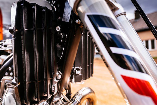
Впрыск топлива в двухтактные двигатели — это крупная революция в мире эндуро. Это звучит абсурдно, но экстремальные нагрузки двигателей в полевых условиях до сих пор были преимуществом для двигателей, в которых смесь воздуха и топлива проходит через карбюратор через систему ламелей. Как суперсила эндуро, KTM первой в мире представила двухтактный впрыск топлива.
13 долгих лет ожидания от первого прототипа до наших дней
На реализацию проекта «впрыска топлива» для двухтактных эндуро мотоциклов KTM потребовалось 13 долгих лет, прежде чем они смогли запустить его в серийное производство. Тем временем Япония решила больше не верить в двухтактные двигатели и прекратила их разработку. Тем временем разразился кризис, произошел бум экстремальных эндуро и резко возрос интерес рынка к двухтактным двигателям. Двухтактные до сих пор живы!

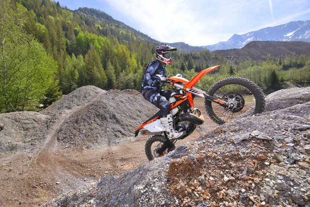
Именно здесь, в самых экстремальных условиях, КТМ прошел интенсивные испытания в прошлом году. Андреас ЛеттенбихлерЗаводской гонщик и пилот-испытатель признались, что были шокированы тем фактом, что им не требовалась настройка двигателя для гонки Roof of Africa, которая проходит высоко в горах Южной Африки: «Обычно мы тратили по крайней мере один день, чтобы оптимально настроить двигатель для гонки, что очень требовательно в этой области, поскольку перепады высоты очень велики, а плохая регулировка может привести не только к неисправности двигателя, но и к отказу двигателя. Двухтактный двигатель также должен получать немного топлива во время спуска для смазки двигателя, иначе он может заблокироваться. На этот раз днем мы пили пиво в тени рядом с отелем ».
KTM в настоящее время занимает первое место в мире внедорожных мотоциклов, и они не намерены отказываться от своего превосходства. Поэтому они много работали и отбросили по крайней мере три заблуждения, которые не проявились на поле (кто знает, сколько они от нас скрывали), но теперь они очень гордятся тем, что они приготовили. Справедливо!
По крайней мере, судя по первому впечатлению, я могу сказать, что это лучший двухтактный двигатель эндуро, на котором я ездил за свою 20-летнюю карьеру журналиста. Насколько они верят в новые модели, подтверждается тем фактом, что нас привезли на печально известную гору Эрцберг, где KTM пережила необычайный успех, и после целого дня пыток на сложной и крутой местности я могу признаться, что был напуган больше, чем когда-либо. на мотоцикле эндуро, но в то же время могу только поздравить разработчиков, которые сделали первый в мире двухтактный двигатель эндуро с непосредственным впрыском топлива. Двухтактный двигатель приводится в действие системой Dell’Ort диаметром 39 мм со смесью бензина и масла для смазки поршня, цилиндра и главного вала. Масло переливается в отдельную емкость. (0,7 литра) и достаточно для От 5 до 6 заправок, который принимает 9 литров чистого бензина.
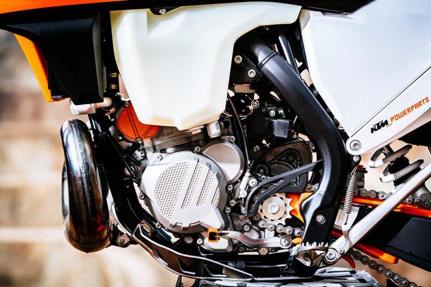
Моторная электроника — это «мозг» работы двигателя
Электроника двигателя, расположенная под сиденьем, представляет собой чрезвычайно сложную систему, которая определяет время зажигания и количество топлива на основе информации, которую она получает от манометра, положения рычага дроссельной заслонки и температуры масла и охлаждающей жидкости. Таким образом, драйвер не требует регулировки, остается только старый. кнопка холодного пуска. В зависимости от нагрузки двигателя электроника постоянно определяет соотношение смеси, что на практике означает, что расход масла снижается вдвое, а расход топлива даже на 30 процентов. В течение дня, когда мы обычно останавливались для фотосъемки и обеда, KTM EXC 300 и 250 TPI потребляли менее 9 литров бензина.
Проехали участки с гонки Red Bull Hare Scramble.
На железной горе ее размеры сначала поражают, вызывают уважение, но, поднимаясь по крутым склонам, в первую очередь задумываешься, можно ли вообще здесь проехать. Но когда вы видите, что кто-то уже проехал впереди вас по тому же склону, вы ложитесь, набираетесь храбрости и открываете газ. Ехали по множеству узких и очень техничных дорожек, где раздражали корни или даже кусок забытой железной трубы, приходилось все время быть начеку, потому что все очень непредсказуемо и может подождать яма или крутой спуск или подъем за поворотом.
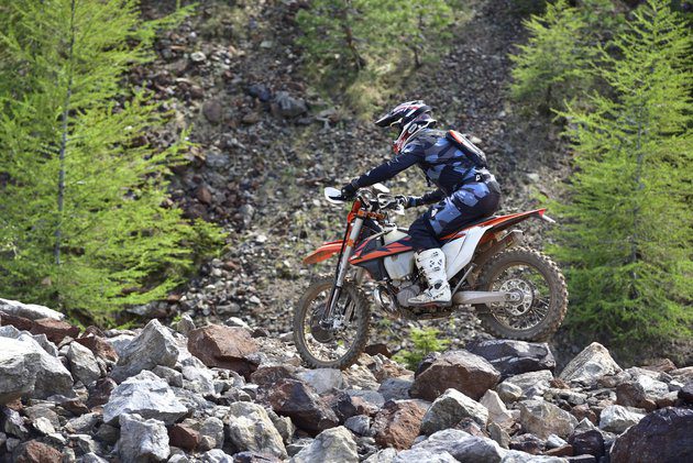
Тогда есть камни, в этом действительно нет недостатка. Над огромными скалами на разрезе ‘Ужин Карла’ К счастью, я проехал только ровную часть, и мы с коллегой из Финляндии попробовали восхождение под громкие аплодисменты других, более сообразительных журналистов, которые наблюдали за всем безопасно с расстояния, и каждый закончил с перевернутым двигателем. Здесь я могу похвалить качество пластика и новую защиту радиаторов (новая и более прочная конструкция, не требующая дополнительной алюминиевой защиты), так как мотоцикл не был поврежден. Прежде всего, на первый план вышли точность гидравлического сцепления, полезная мощность, малый вес и отличная подвеска.
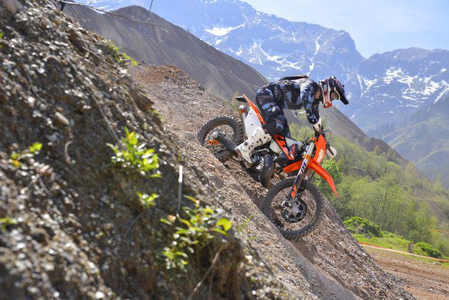
Однако максимальная мощность и точность управления вышли на первый план, когда я наматывал газ на второй или третьей передаче в, казалось бы, невозможные подъемы, такие как печально известный «трубопровод». Не буду терять слов на спусках, потому что они были для меня самыми страшными. Потому что, как только вы доберетесь до вершины горы высотой 1.500 футов, вам придется один раз спуститься, верно? Когда вы находитесь на вершине выступа и даже не видите, куда собираетесь пойти под собой, вам придется рыться в карманах, чтобы найти свое «яйцо **» или храбрость. Но я обнаружил, что обе новые модели эндуро предлагают больше, чем мне нужно, или, скорее, помогают мне лучше ездить в поле самостоятельно.
Поскольку классический карбюратор попрощался, температура воздуха и высота больше не вызывают головной боли, и в результате оба двигателя всегда работают оптимально.
Кривая мощности чрезвычайно линейна, и тот двухтактный внезапный удар, который вызывал у большинства обычных водителей головную боль или даже пугал их, исчез. EXC 300 TPI никоим образом не скрывает своей мощности (KTM заявляет 54 ‘лошадей’) на максимальных скоростях. Вы легко ведете его на третьей передаче, и когда его нужно вытащить из поворота, он немедленно реагирует на решающее ускорение. Мощности всегда достаточно, и если вы знаете, вы можете ездить на ней очень быстро. Возможно, что более важно: вы также можете ошибиться на нем у подножия подъема, так как крутящий момент и мощность сэкономят вас, если вы не обладаете знаниями как мастер Джонни Уокер.
EXC 250 TPI немного слабее, чем 250, но больше всего он показывает эту разницу в мощности при движении по самым крутым склонам. Здесь разница: если вы ошиблись под холмом, гораздо сложнее набрать необходимую скорость и инерцию, чтобы вывести вас на вершину. Чуть меньшая мощность по сравнению с 300 успешно компенсируется более легким управлением на более технически сложной местности и в тестах эндуро на изгибах, а также на узких и извилистых трассах, где влияние вращающихся масс в двигателе менее заметно. Легче переходить от поворота к повороту или преодолевать препятствия в руках.
Эргономика, подвеска, тормоза и качество, как в конструкции, так и в используемых компонентах, находятся на высшем уровне. Руль от Neken, подвеска WP, рычаги Odi с системой затяжки винта, колеса Giant с фрезерованной ступицей с ЧПУ, топливный бак прозрачный и имеет встроенный топливный насос и датчик уровня топлива. Крестовины из кованого железа позволяют регулировать до четырех положений руля. Однако, если всего этого вам недостаточно, у вас есть улучшенная версия с дополнительным оборудованием. Шесть дней, который на этот раз изображен на графике французского флага, так как гонка пройдет осенью во Франции.
Поэтому я тоже как-то понимаю, что цена в хорошие девять тысяч как-то оправдана, но с другой стороны это отражение ситуации на рынке. Двухтактные KTM для эндуро традиционно распродаются первыми каждый год, и я боюсь, что эти оранжевые специальные предложения для эндуро разойдутся, как теплые булочки. Они приходят в салоны в Копере и Гросупле в конце июня или самое позднее в начале июля. Первую небольшую серию уже получили все, кто будет участвовать в гонках в Румынии и Эрцберге.
Петр Кавчич
фото: Себас Ромеро, Марко Кампелли, KTM
Техническая информация
Двигатель (EXC 250/300 TPI): одноцилиндровый, двухтактный, жидкостного охлаждения, 249 / 293,2 см3, впрыск топлива, электрический и ножной запуск двигателя.
Коробка передач, привод: 6-ступенчатая коробка передач, цепь.
Каркас: трубчатый, хром-молибденовый 25CrMo4, двойная клетка.
Тормоза: передние дисковые 260 мм, задние дисковые 220 мм.
Подвеска: передняя регулируемая перевернутая телескопическая вилка WP Xplor 48 мм, ход 300 мм, задний регулируемый одиночный амортизатор WP, ход 310 мм, крепление PDS.
Gume: 90/90-21, 140/80-18.
Высота сиденья (мм): 960 мм.
Топливный бак (л): 9 л.
Колесная база (мм): 1.482 мм.
Чай (кг): 103 кг.
Продажи: Axle Koper тел .: 30 377 334 Seles Moto Grosuplje тел .: 041 527 111
Цена: 250 EXC TPI — 9.329 300 евро; 9.589 EXC TPI — XNUMX евро
- Manuals
- Brands
- KTM Manuals
- Motorcycle
- 300 EXC TPI 2019
Manuals and User Guides for KTM 300 EXC TPI 2019. We have 2 KTM 300 EXC TPI 2019 manuals available for free PDF download: Repair Manual, Setup Instructions
KTM 300 EXC TPI 2019 Repair Manual (387 pages)
Brand: KTM
|
Category: Motorcycle
|
Size: 19.58 MB
Table of Contents
-
Table of Contents
4
-
1 Means of Representation 1
9
-
Symbols Used
9
-
Formats Used
9
-
-
2 Safety Advice
10
-
Repair Manual
10
-
Degrees of Risk and Symbols
10
-
Work Rules
10
-
-
3 Important Notes 3
11
-
Manufacturer and Implied Warranty
11
-
Operating and Auxiliary Substances
11
-
Spare Parts, Accessories
11
-
Figures
11
-
-
4 Serial Numbers
12
-
Chassis Number
12
-
Type Label
12
-
Engine Number
12
-
Fork Part Number
12
-
Shock Absorber Article Number
13
-
-
5 Motorcycle
14
-
Raising the Motorcycle with a Lift Stand
14
-
Removing the Motorcycle from the Lift Stand
14
-
Starting the Vehicle
14
-
Starting the Motorcycle to Check the Function
15
-
-
6 Fork, Triple Clamp
16
-
Adjusting the Compression Damping of the Fork
16
-
Adjusting the Rebound Damping of the Fork
17
-
Adjusting the Spring Preload of the Fork (All Six Days Models)
18
-
Bleeding the Fork Legs
18
-
Cleaning the Dust Boots of the Fork Legs
19
-
Removing the Fork Legs
19
-
Installing the Fork Legs
20
-
Removing the Fork Protector
21
-
Installing the Fork Protector
21
-
All Standard EXC/XC-W Models
22
-
Servicing the Fork
22
-
Disassembling the Fork Legs
22
-
Disassembling the Cartridge
25
-
Disassembling the Tap Compression
28
-
Checking the Fork Legs
29
-
Assembling the Tap Compression
30
-
Assembling the Cartridge
31
-
Assembling the Fork Legs
35
-
Lubricating the Steering Head Bearing
39
-
Removing the Lower Triple Clamp
39
-
Installing the Lower Triple Clamp
40
-
Changing the Steering Head Bearing
42
-
Checking the Play of the Steering Head Bearing
44
-
Adjusting the Steering Head Bearing Play
44
-
All Six Days Models
45
-
Servicing the Fork
45
-
Disassembling the Fork Legs
45
-
Disassembling the Cartridge
48
-
Disassembling the Tap Compression
51
-
Checking the Fork Legs
52
-
Assembling the Tap Compression
53
-
Assembling the Cartridge
54
-
Assembling the Fork Legs
58
-
Lubricating the Steering Head Bearing
63
-
Removing the Lower Triple Clamp
63
-
Installing the Lower Triple Clamp
64
-
Changing the Steering Head Bearing
66
-
Checking the Play of the Steering Head Bearing
67
-
Adjusting the Steering Head Bearing Play
68
-
-
7 Handlebar, Controls 7
69
-
Handlebar Position
69
-
Adjusting the Handlebar Position
69
-
Adjusting the Basic Position of the Clutch Lever
71
-
Checking the Rubber Grip
72
-
Checking Throttle Cable Routing
72
-
Checking the Play in the Throttle Cable
73
-
Adjusting the Play in the Throttle Cable
73
-
Setting the Characteristic Map of the Throttle Response
74
-
-
8 Frame
76
-
Checking the Frame
76
-
Removing the Engine Guard (All Six Days Models)
76
-
Installing the Engine Guard (All Six Days Models)
76
-
Changing the Footrests
76
-
-
9 Shock Absorber, Swingarm
80
-
Adjusting the High-Speed Compression Damping of the Shock Absorber
80
-
Adjusting the Low-Speed Compression Damping of the Shock Absorber
80
-
Adjusting the Rebound Damping of the Shock Absorber
81
-
Measuring the Rear Wheel Dimension Unloaded
82
-
Checking the Static Sag of the Shock Absorber
82
-
Checking the Riding Sag of the Shock Absorber
83
-
Adjusting the Spring Preload of the Shock Absorber
83
-
Adjusting the Riding Sag
84
-
Removing the Shock Absorber
85
-
Installing the Shock Absorber
85
-
Servicing the Shock Absorber
85
-
Removing the Spring
86
-
Disassembling the Damper
87
-
Disassembling the Seal Ring Retainer
88
-
Disassembling the Piston Rod
89
-
Replacing the Pilot Bushing
90
-
Checking the Damper
91
-
Removing the Heim Joint
92
-
Installing the Heim Joint
93
-
Assembling Seal Ring Retainer
93
-
Assembling the Piston Rod
94
-
Assembling the Damper
96
-
Bleeding and Filling the Damper
98
-
Filling Damper with Nitrogen
101
-
Installing the Spring
102
-
Checking the Swingarm
103
-
Checking the Heim Joint for Play
103
-
Changing the Heim Joint
104
-
Changing the Heim Joint on the Swingarm
105
-
Checking the Swingarm Bearing for Play
107
-
Removing the Swingarm
107
-
Installing the Swingarm
108
-
Changing the Swingarm Bearing
110
-
-
10 Exhaust 10
113
-
Removing the Manifold
113
-
Installing the Manifold
114
-
Removing the Main Silencer
115
-
Installing the Main Silencer
116
-
Changing the Glass Fiber Yarn Filling in the Main Silencer
116
-
-
11 Air Filter
118
-
Air Filter
118
-
Removing the Air Filter Box Cover
118
-
Installing the Air Filter Box Cover
118
-
Removing the Air Filter
119
-
Installing the Air Filter
119
-
Cleaning the Air Filter and Air Filter Box
120
-
Preparing Air Filter Box Cover for Securing
120
-
Sealing the Air Filter Box
121
-
-
12 Fuel Tank, Seat, Trim
122
-
Opening the Filler Cap
122
-
Closing the Filler Cap
122
-
Removing the Seat
123
-
Mounting the Seat
123
-
Removing the Fuel Tank
124
-
Installing the Fuel Tank
125
-
Changing the Fuel Screen
127
-
Changing the Fuel Filter
128
-
Changing the Fuel Pump
131
-
Checking the Fuel Pressure
134
-
-
13 Mask, Fender
136
-
Removing Front Fender
136
-
Installing Front Fender
136
-
Removing the Headlight Mask with the Headlight
137
-
Installing the Headlight Mask with the Headlight
137
-
-
14 Wheels 14
139
-
Checking the Tire Air Pressure
139
-
Checking the Tire Condition
139
-
Checking the Wheel Bearing for Play
140
-
Checking the Brake Discs
141
-
Checking the Rim Run-Out
141
-
Checking Spoke Tension
142
-
Front Wheel
143
-
Removing the Front Wheel
143
-
Installing the Front Wheel
144
-
Changing the Front Brake Disc
144
-
Changing Front Wheel Bearing
145
-
Rear Wheel
146
-
Removing the Rear Wheel
146
-
Installing the Rear Wheel
147
-
Changing the Rear Brake Disc
148
-
Changing the Rear Wheel Bearing
149
-
Checking the Chain for Dirt
151
-
Cleaning the Chain
151
-
Checking the Chain Tension
152
-
Checking the Chain, Rear Sprocket, Engine Sprocket, and Chain Guide
153
-
Adjusting the Chain Tension
155
-
Changing the Drivetrain Kit
156
-
-
15 Wiring Harness, Battery 15
159
-
Ignition Curve Plug-In Connector
159
-
Changing the Main Fuse
159
-
Changing the Fuses of Individual Power Consumers
161
-
Disconnecting the Negative Cable of the Battery
162
-
Connecting the Negative Cable of the Battery
163
-
Removing the Battery
163
-
Installing the Battery
164
-
Recharging the Battery
165
-
Checking the Charging Voltage
166
-
Checking the Open-Circuit Current
167
-
Checking the Starter Relay
167
-
Diagnostics Connector
168
-
-
16 Brake System 16
169
-
Checking the Front Brake Linings
169
-
Changing the Front Brake Linings
169
-
Checking the Free Travel of the Hand Brake Lever
171
-
Adjusting Free Travel of Hand Brake Lever (All EXC Models)
172
-
Adjusting the Basic Position of the Hand Brake Lever (All XC-W Models)
172
-
Checking the Front Brake Fluid Level
172
-
Adding Front Brake Fluid
173
-
Changing the Front Brake Fluid
174
-
Checking the Brake Linings of the Rear Brake
176
-
Changing the Rear Brake Linings
176
-
Checking the Free Travel of Foot Brake Lever
178
-
Adjusting the Basic Position of the Foot Brake Lever
179
-
Checking the Rear Brake Fluid Level
180
-
Adding Rear Brake Fluid
180
-
Changing the Rear Brake Fluid
181
-
-
17 Lighting System, Instruments
184
-
Changing the Headlight Bulb
184
-
Changing the Turn Signal Bulb (All EXC Models)
184
-
Checking the Headlight Setting
185
-
Adjusting the Headlight Range
186
-
Changing the Combination Instrument
186
-
Combination Instrument Overview
187
-
Activation and Test
187
-
Setting the Kilometers or Miles
187
-
Adjusting the Combination Instrument Function
188
-
Setting the Clock
189
-
Activating Additional Functions
189
-
Setting the Wheel Circumference
190
-
Viewing the Lap Time
190
-
-
18 Engine
192
-
Cleaning the Pressure Sensor Hose
192
-
Removing the Engine
192
-
Installing the Engine
198
-
Engine Disassembly
205
-
Clamping the Engine into the Engine Work Stand
205
-
Removing the Shift Lever
205
-
Removing the Clutch Push Rod
205
-
Draining the Gear Oil
205
-
Removing the Spacer
206
-
Removing the Alternator Cover
206
-
Removing the Kick Starter
207
-
Removing Injection Valves
207
-
Removing the Cylinder Head
207
-
Removing the Cylinder
208
-
Removing the Piston
210
-
Removing the Water Pump Cover
211
-
Removing the Clutch Cover
211
-
Removing the Clutch Discs
212
-
Removing the Clutch Basket
213
-
Removing the Balancer Shaft
214
-
Removing the Kick Starter Shaft
215
-
Removing the Intermediate Kick Starter Gear
215
-
Removing the Shift Shaft
216
-
Removing the Shift Drum Locating Unit
216
-
Removing the Locking Lever
216
-
Removing the Rotor
216
-
Removing the Starter Motor
217
-
Removing the Reed Valve Housing
218
-
Removing the Left Engine Case Section
219
-
Removing the Shift Rails
219
-
Removing the Shift Drum
219
-
Removing the Shift Forks
220
-
Removing the Transmission Shafts
220
-
Removing the Crankshaft
220
-
Working on Individual Parts
221
-
Working on the Right Section of the Engine Case
221
-
Working on the Left Section of the Engine Case
222
-
Removing the Crankshaft Bearing Inner Race
224
-
Installing the Crankshaft Bearing Inner Race
224
-
Changing the Connecting Rod, Conrod Bearing, and Crank Pin
225
-
Checking the Crankshaft Run-Out at the Bearing Pin
226
-
Checking/Measuring the Cylinder
226
-
Cleaning the Pressure Sensor Cylinder Connection
227
-
Removing the Exhaust Control
227
-
Checking the Exhaust Control
229
-
Installing the Exhaust Control
231
-
Cylinder — Nikasil Coating
234
-
Checking/Measuring the Piston
234
-
Checking the Piston Ring End Gap
235
-
Measuring the Piston/Cylinder Mounting Clearance
235
-
Disassemble the Reed Valve Housing
236
-
Checking the Reed Valve Housing, Reed Valve and Intake Flange
237
-
Assemble the Reed Valve Housing
237
-
Working on the Clutch Cover
239
-
Checking the Clutch
242
-
Preassembling Shift Shaft
243
-
Checking the Shift Mechanism
244
-
Disassembling the Main Shaft
245
-
Disassembling the Countershaft
246
-
Checking the Transmission
246
-
Assembling the Main Shaft
248
-
Assembling the Countershaft
248
-
Checking the Kick Starter
250
-
Preassembling the Kick Starter Shaft
250
-
Checking the Electric Starter Drive
251
-
Engine Assembly
252
-
Installing the Crankshaft
252
-
Installing the Transmission Shafts
253
-
Installing the Shift Forks
253
-
Installing the Shift Drum
254
-
Installing the Shift Rails
254
-
Installing the Left Engine Case Section
254
-
Installing the Reed Valve Housing
255
-
Installing the Starter Motor
256
-
Installing the Rotor
257
-
Installing the Locking Lever
257
-
Installing the Shift Drum Locating Unit
258
-
Installing the Shift Shaft
258
-
Installing the Intermediate Kick Starter Gear
258
-
Installing the Kick Starter Shaft
258
-
Installing the Balancer Shaft
259
-
Installing the Clutch Basket
260
-
Installing the Clutch Discs
261
-
Installing the Clutch Cover
263
-
Installing the Water Pump Cover
265
-
Installing the Piston
266
-
Installing the Cylinder
267
-
Checking the X-Distance
269
-
Adjusting the X-Distance
269
-
Adjusting the Z-Distance
271
-
Installing the Cylinder Head
273
-
Installing Injection Valves
274
-
Installing the Kick Starter
274
-
Installing the Alternator Cover
274
-
Installing the Spacer
275
-
Installing the Gear Oil Drain Plug
275
-
Installing the Clutch Push Rod
276
-
Installing the Shift Lever
276
-
Removing the Engine from the Engine Work Stand
276
-
-
-
19 Clutch 19
277
-
Checking/Correcting the Fluid Level of the Hydraulic Clutch
277
-
Changing the Hydraulic Clutch Fluid
278
-
Checking the Clutch
279
-
-
20 Water Pump, Cooling System
288
-
Cooling System
288
-
Checking the Antifreeze and Coolant Level
288
-
Checking the Coolant Level
289
-
Draining the Coolant
289
-
Refilling with Coolant
290
-
-
21 Exhaust Control 21
293
-
Checking/Adjusting the Exhaust Control
293
-
-
22 Lubrication System
296
-
Changing the Gear Oil
296
-
Checking the Gear Oil Level
297
-
Adding Gear Oil
297
-
Checking 2-Stroke Oil Level
298
-
Opening 2-Stroke Oil Tank Cap
299
-
Adding 2-Stroke Oil
299
-
Closing 2-Stroke Oil Tank Cap
299
-
Priming the Oil Pump
300
-
Replacing the Oil Pump
301
-
-
23 Ignition System
304
-
Checking the Ignition System
304
-
Ignition Coil — Checking the Primary Winding
305
-
Checking the Spark Plug Connector
306
-
Alternator — Checking the Stator Winding
306
-
Checking the Crankshaft Position Sensor
307
-
Changing the Spark Plug
308
-
Changing the Spark Plug and Spark Plug Connector
309
-
Removing the Stator
309
-
Installing the Stator
310
-
-
24 Electric Starter 24
311
-
Checking the Starter Motor
311
-
-
25 Throttle Valve Body
312
-
Adjusting the Idle Speed
312
-
Programming Ambient Pressure
312
-
Cold Start Button
313
-
-
26 Technical Data
314
-
Engine
314
-
All 250 Models
314
-
All 300 Models
314
-
Tolerance, Engine Wear Limits
315
-
Engine Tightening Torques
316
-
Capacities
317
-
Gear Oil
317
-
Engine Oil
317
-
Coolant
317
-
Fuel
318
-
Chassis
318
-
Electrical System
319
-
Tires
319
-
Fork
319
-
All Standard EXC/XC-W Models
319
-
All Six Days Models
320
-
Shock Absorber
320
-
Chassis Tightening Torques
321
-
-
27 Cleaning, Care
324
-
Cleaning, Care
324
-
Cleaning the Motorcycle
324
-
Checks and Maintenance Steps for Winter Operation
325
-
-
28 Storage
326
-
Preparing for Use after Storage
327
-
-
29 Service Schedule
328
-
Additional Information
328
-
Required Work
328
-
Recommended Work
329
-
-
30 Wiring Diagram
332
-
All EXC Models)
332
-
All EXC Models)
334
-
All EXC Models)
336
-
All EXC Models)
338
-
All EXC Models)
340
-
All EXC Models)
342
-
All EXC Models)
344
-
All EXC Models)
346
-
All XC-W Models)
348
-
All XC-W Models)
350
-
All XC-W Models)
352
-
All XC-W Models)
354
-
All XC-W Models)
356
-
All XC-W Models)
358
-
-
31 Substances
360
-
32 Auxiliary Substances
362
-
33 Special Tools
364
-
34 Standards 34
379
-
35 Index of Special Terms
380
-
36 List of Abbreviations 36
381
-
Index
382
-
Advertisement

KTM 300 EXC TPI 2019 Setup Instructions (45 pages)
Brand: KTM
|
Category: Motorcycle
|
Size: 2.76 MB
Table of Contents
-
Means of Representation
4
-
Mount and Tighten Screws
7
-
Remove Screws
21
-
Mount and Tighten Screw
24
-
Tighten Screws 3 . Guideline
28
-
Adding 2-Stroke Oil
35
-
Setting the Clock
39
-
Technical Data
40
-
Auxiliary Substances
43
Advertisement
Related Products
-
KTM 300 EXC TPI
-
KTM 300 EXC TPI EU 2018
-
KTM 300 EXC TPI 2020
-
KTM 300 EXC TPI ERZBERGRODEO 2020
-
KTM 300 EXC TPI EU 2021
-
KTM 300 EXC TPI ERZBERGRODED EU 2021
-
KTM 300 EXC BR 2016
-
KTM 300 EXC EU 2016
-
KTM 300 EXC AUS 2014
-
KTM 300 EXC EU 2014
KTM Categories
Motorcycle
Motorcycle Accessories
Offroad Vehicle
Engine
Industrial Equipment
More KTM Manuals
Информация, представленная на Сайте, носит информационный характер и ни при каких условиях не является публичной
офертой, определяемой положениями статьи 437 Гражданского кодекса Российской Федерации. Все содержащиеся на
Сайте сведения носят исключительно информационный характер и не являются исчерпывающими. Все условия
приобретения мототехники, цены, спецпредложения и комлектации мототехники указаны с целью ознакомления.
Комплектации и цены действительны на момент публикации и могут быть изменены без предварительного оповещения.
Представленная на Сайте мототехника может быть укомплектована дополнительным оборудованием, не входящим в
стандартную версию, но доступным за дополнительную плату. Сведения о продукции, касающиеся объёмов поставки,
внешнего вида, характеристик, габаритов и веса, эксплуатационных затрат и т.д. не являются обязательными,
рассматриваются как приблизительные и указаны с условием того, что могут возникнуть ошибки при печати, настройке
и/или наборе текста. Такая информация может быть изменена без предварительного уведомления. Чтобы получить
полную информацию о продукции, услугах, дополнительном оборудовании и спецпредложениях, интересных для Вас,
обращайтесь к менеджерам Дилерского центра
- Manuals
- Brands
- KTM Manuals
- Motorcycle
- 300 EXC
Manuals and User Guides for KTM 300 EXC. We have 15 KTM 300 EXC manuals available for free PDF download: Repair Manual, Owner’s Manual, Owner’s Handbook Manual, Manual
KTM 300 EXC Repair Manual (289 pages)
Brand: KTM
|
Category: Motorcycle
|
Size: 12.59 MB
Table of Contents
-
Table of Contents
4
-
Table of Contents 2
4
-
1 Means of Representation
8
-
Symbols Used
8
-
Formats Used
8
-
-
2 Safety Advice
9
-
Repair Manual
9
-
Degrees of Risk and Symbols
9
-
Work Rules
9
-
-
3 Important Information
10
-
Guarantee, Warranty
10
-
Operating and Auxiliary Substances
10
-
Spare Parts, Accessories
10
-
Figures
10
-
-
4 Serial Numbers
11
-
Chassis Number
11
-
Type Label
11
-
Engine Number
11
-
Fork Part Number
11
-
Shock Absorber Part Number
11
-
-
5 Motorcycle
12
-
Raising the Motorcycle with the Lift Stand
12
-
Removing the Motorcycle from the Lift Stand
12
-
Starting
12
-
Starting the Motorcycle for Checking
13
-
-
6 Fork, Triple Clamp
14
-
Exc Eu/Aus, XC-W
14
-
Adjusting the Compression Damping of the Fork
14
-
Adjusting the Rebound Damping of the Fork
14
-
Adjusting the Spring Preload of the Fork
14
-
Bleeding the Fork Legs
15
-
Cleaning the Dust Boots of the Fork Legs
15
-
Loosening the Fork Protection
16
-
Positioning the Fork Protection
16
-
Removing the Fork Legs
16
-
Installing the Fork Legs
16
-
Removing the Fork Protector
17
-
Installing the Fork Protector
17
-
Performing a Fork Service
18
-
Disassembling the Fork Legs
18
-
Cartridge Disassembly
21
-
Disassembling the Compression Damping Fitting
23
-
Checking the Fork Legs
23
-
Assembling the Compression Damping Fitting
24
-
Assembling the Cartridge
25
-
Assembling the Fork Legs
26
-
Greasing the Steering Head Bearing
31
-
Removing the Lower Triple Clamp
31
-
Installing the Lower Triple Clamp
32
-
Checking the Play of the Steering Head Bearing
33
-
Adjusting the Play of the Steering Head Bearing
34
-
250/300 Six Days
34
-
Adjusting the Compression Damping of the Fork
34
-
Adjusting the Rebound Damping of the Fork
35
-
Bleeding the Fork Legs
35
-
Cleaning the Dust Boots of the Fork Legs
35
-
Loosening the Fork Protection
36
-
Positioning the Fork Protection
36
-
Removing the Fork Legs
36
-
Installing the Fork Legs
37
-
Removing the Fork Protector
37
-
Installing the Fork Protector
38
-
Performing a Fork Service
38
-
Disassembling the Fork Legs
38
-
Removing the Spring
40
-
Disassembling the Cartridge
41
-
Disassembling the Piston Rod
42
-
Disassembling the Hydrostop Unit
43
-
Disassembling the Seal Ring Retainer
44
-
Checking the Fork Legs
44
-
Assembling the Seal Ring Retainer
45
-
Assembling the Hydrostop Unit
46
-
Assembling the Piston Rod
46
-
Assembling the Cartridge
48
-
Assembling the Fork Legs
49
-
Greasing the Steering Head Bearing
52
-
Removing the Lower Triple Clamp
53
-
Installing the Lower Triple Clamp
53
-
Checking the Play of the Steering Head Bearing
55
-
Adjusting the Play of the Steering Head Bearing
55
-
-
7 Handlebar, Controls
56
-
Handlebar Position
56
-
Adjusting the Handlebar Position
56
-
Adjusting the Basic Position of the Clutch Lever
56
-
Checking the Routing of the Throttle Cable
57
-
Checking the Play in the Throttle Cable
57
-
Adjusting the Play in the Throttle Cable
58
-
-
8 Frame
59
-
Removing the Engine Guard (250/300 SIX DAYS)
59
-
Installing the Engine Guard (250/300 SIX DAYS)
59
-
-
9 Shock Absorber, Swingarm
60
-
Adjusting the High-Speed Compression Damping of the Shock Absorber
60
-
Adjusting the Low-Speed Compression Damping of the Shock Absorber
60
-
Adjusting the Rebound Damping of the Shock Absorber
61
-
Measuring the Sag of the Unloaded Rear Wheel
61
-
Checking the Static Sag of the Shock Absorber
61
-
Checking the Riding Sag of the Shock Absorber
62
-
Adjusting the Spring Preload of the Shock Absorber
62
-
Adjusting the Riding Sag
63
-
Removing the Shock Absorber
63
-
Installing the Shock Absorber
63
-
Servicing the Shock Absorber
64
-
Removing the Spring
64
-
Disassembling the Damper
65
-
Disassembling the Piston Rod
66
-
Disassembling the Seal Ring Retainer
67
-
Replacing the Pilot Bushing
68
-
Checking the Damper
69
-
Disassembling the Rebound Adjuster
69
-
Removing the Heim Joint
70
-
Installing the Heim Joint
71
-
Assembling the Rebound Adjuster
72
-
Assembling the Seal Ring Retainer
72
-
Assembling the Piston Rod
73
-
Assembling the Damper
74
-
Bleeding and Filling the Damper
77
-
Filling the Damper with Nitrogen
79
-
Installing the Spring
80
-
Changing the Heim Joint
81
-
-
10 Exhaust
83
-
Removing the Main Silencer
83
-
Installing the Main Silencer
83
-
Changing the Glass Fiber Yarn Filling of the Main Silencer
83
-
-
11 Air Filter
85
-
Removing the Air Filter Box Lid
85
-
Installing the Air Filter Box Lid
85
-
Removing the Air Filter
85
-
Installing the Air Filter
85
-
Cleaning the Air Filter and Air Filter Box
86
-
Sealing the Air Filter Box
86
-
-
12 Fuel Tank, Seat, Trim
87
-
Opening the Filler Cap
87
-
Closing the Filler Cap
87
-
Removing the Seat
87
-
Mounting the Seat
88
-
Removing the Fuel Tank
88
-
Installing the Fuel Tank
89
-
Fuel Tap
90
-
-
13 Mask, Fender
91
-
Removing the Front Fender
91
-
Installing the Front Fender
91
-
Removing the Headlight Mask with the Headlight
91
-
Refitting the Headlight Mask with the Headlight
92
-
Advertisement

KTM 300 EXC Owner’s Manual (150 pages)
2014
Brand: KTM
|
Category: Motorcycle
|
Size: 3.99 MB
Table of Contents
-
Table of Contents
4
-
1 Means of Representation
7
-
Symbols Used
7
-
Formats Used
7
-
-
2 Safety Advice
8
-
Use Definition — Intended Use
8
-
Degrees of Risk and Symbols
8
-
Tampering Warning
8
-
Safe Operation
9
-
Protective Clothing
9
-
Work Rules
9
-
Environment
9
-
Owner’s Manual
9
-
-
3 Important Notes
10
-
Guarantee, Warranty
10
-
Operating and Auxiliary Substances
10
-
Spare Parts, Accessories
10
-
Service
10
-
Figures
10
-
Customer Service
10
-
-
4 View of Vehicle
11
-
View of Vehicle, Front Left (Example)
11
-
View of Vehicle, Rear Right (Example)
12
-
-
5 Serial Numbers
13
-
Chassis Number
13
-
Type Label
13
-
Key Number (All EXC Models)
13
-
Engine Number
13
-
Fork Part Number
13
-
Shock Absorber Part Number
14
-
-
6 Controls
15
-
Clutch Lever
15
-
Hand Brake Lever
15
-
Throttle Grip
15
-
Kill Switch (All EXC Models)
15
-
Kill Switch (All XC-W Models)
16
-
Horn Button (All EXC Models)
16
-
Light Switch (All EXC Models)
16
-
Light Switch (All XC-W Models)
16
-
Turn Signal Switch (All EXC Models)
16
-
Emergency off Switch (EXC AUS)
17
-
Electric Starter Button (200/250/300 EXC EU, 250/300 SIX DAYS, XC-W)
17
-
Electric Starter Button (EXC AUS)
17
-
Overview of Indicator Lamps (EXC EU/AUS)
17
-
Overview of Indicator Lamps (SIX DAYS EU)
17
-
Overview of Indicator Lamps (300 XC-W SIX DAYS USA)
18
-
Opening the Filler Cap
18
-
Closing the Filler Cap
18
-
Fuel Tap
19
-
Choke
19
-
Shift Lever
19
-
Kick Starter
20
-
Foot Brake Lever
20
-
Side Stand
20
-
Steering Lock (All EXC Models)
20
-
Locking the Steering (All EXC Models)
21
-
Unlocking the Steering (All EXC Models)
21
-
-
7 Speedometer
22
-
Exc, XC-W
22
-
Speedometer Overview
22
-
Activation and Test
22
-
Setting Kilometers or Miles
22
-
Adjusting the Speedometer Functions
23
-
Setting the Clock
23
-
Querying Lap Time
23
-
Display Mode SPEED (Speed)
24
-
Display Mode SPEED/H (Service Hours)
24
-
Setup Menu
24
-
Unit of Measurement Menu
25
-
Display Mode SPEED/CLK (Time)
25
-
Setting the Clock
25
-
Display Mode SPEED/LAP (Lap Time)
26
-
Viewing the Lap Time
26
-
Display Mode SPEED/ODO (Odometer)
26
-
Display Mode SPEED/TR1 (Trip Master 1)
26
-
Display Mode SPEED/TR2 (Trip Master 2)
27
-
Setting TR2 (Trip Master 2)
27
-
Display Mode SPEED/A1 (Average Speed 1)
27
-
Display Mode SPEED/A2 (Average Speed 2)
28
-
Display Mode SPEED/S1 (Stop Watch 1)
28
-
Display Mode SPEED/S2 (Stop Watch 2)
28
-
Table of Functions
28
-
Table of Conditions and Menu Activation
29
-
Six Days
29
-
Speedometer Overview
29
-
Activation and Test
30
-
Setting Kilometers or Miles
30
-
Setting the Speedometer Functions
30
-
Setting the Clock
31
-
Viewing the Lap Time
31
-
Display Mode SPEED (Speed)
32
-
Display Mode SPEED/H (Service Hours)
32
-
Setup Menu
32
-
Setting the Unit of Measurement
33
-
Display Mode SPEED/CLK (Time)
33
-
Setting the Clock
33
-
Display Mode SPEED/LAP (Lap Time)
34
-
Viewing the Lap Time
34
-
Display Mode SPEED/ODO (Odometer)
34
-
Display Mode SPEED/TR1 (Trip Master 1)
34
-
Display Mode SPEED/TR2 (Trip Master 2)
35
-
Setting TR2 (Trip Master 2)
35
-
Display Mode SPEED/A1 (Average Speed 1)
35
-
Display Mode SPEED/A2 (Average Speed 2)
36
-
Display Mode SPEED/S1 (Stop Watch 1)
36
-
Display Mode SPEED/S2 (Stop Watch 2)
36
-
Table of Functions
37
-
Table of Conditions and Menu Activation
38
-
KTM 300 EXC Owner’s Manual (154 pages)
Brand: KTM
|
Category: Motorcycle
|
Size: 7.42 MB
Table of Contents
-
Table of Contents
4
-
1 Means of Representation
7
-
Symbols Used
7
-
Formats Used
7
-
-
2 Safety Advice
8
-
Use Definition — Intended Use
8
-
Degrees of Risk and Symbols
8
-
Tampering Warning
8
-
Safe Operation
9
-
Protective Clothing
9
-
Work Rules
9
-
Environment
9
-
Owner’s Manual
9
-
-
3 Important Notes
10
-
Guarantee, Warranty
10
-
Operating and Auxiliary Substances
10
-
Spare Parts, Accessories
10
-
Service
10
-
Figures
10
-
Customer Service
10
-
-
4 View of Vehicle
11
-
View of Vehicle, Front Left (Example)
11
-
View of Vehicle, Rear Right (Example)
12
-
-
5 Serial Numbers
13
-
Chassis Number
13
-
Type Label
13
-
Key Number (All EXC Models)
13
-
Engine Number
13
-
Fork Part Number
13
-
Shock Absorber Part Number
14
-
-
6 Controls
15
-
Clutch Lever
15
-
Hand Brake Lever
15
-
Throttle Grip
15
-
Kill Switch (All EXC Models)
15
-
Kill Switch (All XC-W Models)
16
-
Horn Button (All EXC Models)
16
-
Light Switch (All EXC Models)
16
-
Light Switch (All XC-W Models)
16
-
Turn Signal Switch (All EXC Models)
16
-
Emergency off Switch (EXC AU)
17
-
Electric Starter Button (All 200/250/300 EU/US Models, 300 EXC BR)
17
-
Electric Starter Button (EXC AU)
17
-
Overview of Indicator Lamps (All EXC Models)
17
-
Overview of Indicator Lamps (All XC-W Models)
17
-
Opening the Filler Cap
18
-
Closing the Filler Cap
18
-
Fuel Tap
19
-
Choke
19
-
Shift Lever
19
-
Kick Starter
20
-
Foot Brake Lever
20
-
Side Stand
20
-
Steering Lock (All EXC Models)
20
-
Locking the Steering (All EXC Models)
21
-
Unlocking the Steering (All EXC Models)
21
-
-
7 Speedometer
22
-
Speedometer Overview
22
-
Activation and Test
22
-
Setting Kilometers or Miles
22
-
Setting the Speedometer Functions
23
-
Setting the Clock
23
-
Viewing the Lap Time
23
-
Display Mode SPEED (Speed)
24
-
Display Mode SPEED/H (Service Hours)
24
-
Setup Menu
25
-
Setting the Unit of Measurement
25
-
Display Mode SPEED/CLK (Time)
26
-
Setting the Clock
26
-
Display Mode SPEED/LAP (Lap Time)
26
-
Viewing the Lap Time
27
-
Display Mode SPEED/ODO (Odometer)
27
-
Display Mode SPEED/TR1 (Trip Master 1)
27
-
Display Mode SPEED/TR2 (Trip Master 2)
28
-
Setting TR2 (Trip Master 2)
28
-
Display Mode SPEED/A1 (Average Speed 1)
28
-
Display Mode SPEED/A2 (Average Speed 2)
29
-
Display Mode SPEED/S1 (Stop Watch 1)
29
-
Display Mode SPEED/S2 (Stop Watch 2)
29
-
Table of Functions
30
-
Table of Conditions and Menu Activation
31
-
-
8 Preparing for Use
32
-
Advice on First Use
32
-
Running in the Engine
33
-
Preparing the Vehicle for Difficult Riding Conditions
33
-
Preparations for Riding on Dry Sand
34
-
Preparations for Riding on Wet Sand
34
-
Preparations for Riding on Wet and Muddy Surfaces
35
-
Preparations for Riding at High Temperatures and Low Speeds
35
-
Preparing for Riding at Low Temperatures or in Snow
36
-
-
9 Riding Instructions
37
-
Checks and Maintenance Work When Preparing for Use
37
-
Starting
37
-
Start off
38
-
Shifting, Riding
38
-
Braking
38
-
Stopping, Parking
39
-
Transport
39
-
Refueling
40
-
-
10 Service Schedule
41
-
Service Work (as Additional Order)
42
-
Advertisement
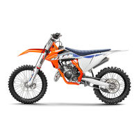
KTM 300 EXC Owner’s Manual (145 pages)
Brand: KTM
|
Category: Motorcycle
|
Size: 7.05 MB
Table of Contents
-
Table of Contents
4
-
Table of Contents 2
4
-
1 Means of Representation
7
-
Symbols Used
7
-
Formats Used
7
-
-
2 Safety Advice
8
-
Use Definition — Intended Use
8
-
Degrees of Risk and Symbols
8
-
Tampering Warning
8
-
Safe Operation
9
-
Protective Clothing
9
-
Work Rules
9
-
Environment
9
-
Owner’s Manual
9
-
-
3 Important Notes
10
-
Guarantee, Warranty
10
-
Operating and Auxiliary Substances
10
-
Spare Parts, Accessories
10
-
Service
10
-
Figures
10
-
Customer Service
10
-
-
4 View of Vehicle
11
-
View of Vehicle, Front Left (Example)
11
-
View of Vehicle, Rear Right (Example)
12
-
-
5 Serial Numbers
13
-
Chassis Number
13
-
Type Label
13
-
Key Number (All EXC Models)
13
-
Engine Number
13
-
Fork Part Number
13
-
Shock Absorber Part Number
14
-
-
6 Controls
15
-
Clutch Lever
15
-
Hand Brake Lever
15
-
Throttle Grip
15
-
Kill Switch (EXC EU/AU, EXC Factory Edition, 300 EXC BR)
15
-
Kill Switch (Six Days EU)
16
-
Kill Switch (All XC-W Models)
16
-
Horn Button (EXC EU/AU, EXC Factory Edition, 300 EXC BR)
16
-
Horn Button (Six Days EU)
16
-
Light Switch (EXC EU/AU, EXC Factory Edition, 300 EXC BR)
16
-
Light Switch (Six Days EU)
17
-
Light Switch (All XC-W Models)
17
-
Turn Signal Switch (EXC EU/AU, EXC Factory Edition, 300 EXC BR)
17
-
Turn Signal Switch (Six Days EU)
17
-
Emergency off Switch (EXC AU)
17
-
Electric Starter Button (All 200/250/300 EU/US Models, 300 EXC BR)
18
-
Electric Starter Button (EXC AU)
18
-
Overview of Indicator Lamps (All EXC Models)
18
-
Overview of Indicator Lamps (All XC-W Models)
18
-
Opening the Filler Cap
18
-
Closing the Filler Cap
19
-
Fuel Tap
19
-
Choke
20
-
Shift Lever
20
-
Kick Starter
20
-
Foot Brake Lever
20
-
Side Stand
21
-
Steering Lock (All EXC Models)
21
-
Locking the Steering (All EXC Models)
21
-
Unlocking the Steering (All EXC Models)
22
-
-
7 Speedometer
23
-
Speedometer Overview
23
-
Activation and Test
23
-
Setting Kilometers or Miles
23
-
Setting the Speedometer Functions
24
-
Setting the Clock
24
-
Viewing the Lap Time
24
-
Display Mode SPEED (Speed)
25
-
Display Mode SPEED/H (Service Hours)
25
-
Setup Menu
25
-
Setting the Unit of Measurement
26
-
Display Mode SPEED/CLK (Time)
26
-
Setting the Clock
27
-
Display Mode SPEED/LAP (Lap Time)
27
-
Viewing the Lap Time
27
-
Display Mode SPEED/ODO (Odometer)
28
-
Display Mode SPEED/TR1 (Trip Master 1)
28
-
Display Mode SPEED/TR2 (Trip Master 2)
28
-
Setting TR2 (Trip Master 2)
28
-
Display Mode SPEED/A1 (Average Speed 1)
29
-
Display Mode SPEED/A2 (Average Speed 2)
29
-
Display Mode SPEED/S1 (Stop Watch 1)
30
-
Display Mode SPEED/S2 (Stop Watch 2)
30
-
Table of Functions
30
-
Table of Conditions and Menu Activation
31
-
-
8 Preparing for Use
32
-
Advice on First Use
32
-
Running in the Engine
33
-
Preparing the Vehicle for Difficult Riding Conditions
33
-
Preparations for Riding on Dry Sand
34
-
Preparations for Riding on Wet Sand
34
-
Preparations for Riding on Wet and Muddy Surfaces
35
-
Preparations for Riding at High Temperatures and Low Speeds
35
-
Preparing for Riding at Low Temperatures or in Snow
36
-
-
9 Riding Instructions
37
-
Checks and Maintenance Work When Preparing for Use
37
-
Starting
37
-
Start off
38
-
Shifting, Riding
38
-
Braking
38
-
Stopping, Parking
39
-
Transport
39
-
Refueling
40
-
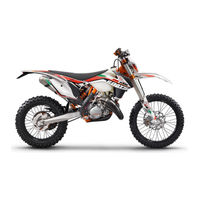
KTM 300 EXC Owner’s Manual (139 pages)
201 year
Brand: KTM
|
Category: Motorcycle
|
Size: 4.41 MB
Table of Contents
-
Table of Contents
4
-
1 Means of Representation
7
-
Symbols Used
7
-
Formats Used
7
-
-
2 Safety Advice
8
-
Use Definition — Intended Use
8
-
Degrees of Risk and Symbols
8
-
Tampering Warning
8
-
Safe Operation
9
-
Protective Clothing
9
-
Work Rules
9
-
Environment
9
-
Owner’s Manual
9
-
-
3 Important Notes
10
-
Guarantee, Warranty
10
-
Operating and Auxiliary Substances
10
-
Spare Parts, Accessories
10
-
Service
10
-
Figures
10
-
Customer Service
10
-
-
4 View of Vehicle
11
-
View of Vehicle, Front Left (Example)
11
-
View of Vehicle, Rear Right (Example)
12
-
-
5 Serial Numbers
13
-
Chassis Number
13
-
Type Label
13
-
Key Number (All EXC Models)
13
-
Engine Number
13
-
Fork Part Number
13
-
Shock Absorber Part Number
14
-
-
6 Controls
15
-
Clutch Lever
15
-
Hand Brake Lever
15
-
Throttle Grip
15
-
Kill Switch (All EXC Models)
15
-
Kill Switch (XC-W)
16
-
Horn Button (All EXC Models)
16
-
Light Switch (All EXC Models)
16
-
Light Switch (XC-W)
16
-
Turn Signal Switch (All EXC Models)
16
-
Emergency off Switch (EXC AUS)
17
-
Electric Starter Button (200/250/300 EXC EU, 250/300 EXC SIX DAYS EU, XC-W)
17
-
Electric Starter Button (EXC AUS)
17
-
Overview of Indicator Lamps (All EXC Models)
17
-
Speedometer
17
-
Overview
17
-
Activation and Test
18
-
Tripmaster Switch
18
-
Setting Kilometers or Miles
18
-
Adjusting the Speedometer Functions
18
-
Setting the Clock
19
-
Querying Lap Time
19
-
Display Mode SPEED (Speed)
20
-
Display Mode SPEED/H (Operating Hours)
20
-
Display Mode SPEED/CLK (Clock)
20
-
Display Mode SPEED/LAP (Lap Time)
21
-
Display Mode SPEED/ODO (Odometer)
21
-
Display Mode SPEED/TR1 (Trip Master 1)
21
-
Display Mode SPEED/TR2 (Trip Master 2)
21
-
Display Mode SPEED/A1 (Average Speed 1)
22
-
Display Mode SPEED/A2 (Average Speed 2)
22
-
Display Mode SPEED/S1 (Stop Watch 1)
22
-
Display Mode SPEED/S2 (Stop Watch 2)
23
-
6.14.19 Table of Functions
23
-
6.14.20 Table of Conditions and Menu Activation
23
-
Opening the Filler Cap
24
-
Closing the Filler Cap
24
-
Fuel Tap
25
-
Choke
25
-
Shift Lever
25
-
Kick Starter
26
-
Foot Brake Lever
26
-
Side Stand
26
-
Steering Lock (All EXC Models)
26
-
Locking the Steering (All EXC Models)
27
-
Unlocking the Steering (All EXC Models)
27
-
-
7 Preparing for Use
28
-
Advice on First Use
28
-
Running in the Engine
29
-
Preparing the Vehicle for Difficult Riding Conditions
29
-
Preparations for Riding on Dry Sand
30
-
Preparations for Riding on Wet Sand
30
-
Preparations for Riding on Wet and Muddy Surfaces
31
-
Preparations for Riding at High Temperatures and Low Speeds
31
-
Preparing for Riding at Low Temperatures or in Snow
32
-
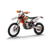
KTM 300 EXC Owner’s Manual (136 pages)
2012 Motorcycle
Brand: KTM
|
Category: Motorcycle
|
Size: 4.26 MB
Table of Contents
-
Table of Contents
4
-
Means of Representation
7
-
Important Information
8
-
View of Vehicle
10
-
View of Vehicle, Front Left (Example)
10
-
View of Vehicle, Rear Right (Example)
11
-
-
Serial Numbers
12
-
Chassis Number
12
-
Type Label
12
-
Key Number (All EXC Models)
12
-
Engine Number
13
-
Fork Part Number
13
-
Shock Absorber Part Number
13
-
-
Controls
14
-
Clutch Lever
14
-
Hand Brake Lever
14
-
Throttle Grip
14
-
Kill Switch (All EXC Models)
14
-
Short Circuit Button (XC-W)
15
-
Light Switch (All EXC Models)
15
-
Turn Signal Switch (All EXC Models)
15
-
Horn Button (All EXC Models)
15
-
Emergency off Switch (200 EXC AUS)
15
-
Emergency off Switch (250/300 EXC AUS)
16
-
Electric Starter Button (250/300 EXC EU, EXC SIX DAYS, 250/300 XC-W)
16
-
Electric Starter Button (250/300 EXC AUS)
16
-
Light Switch (XC-W)
16
-
Overview of Indicator Lamps (All EXC Models)
16
-
Speedometer
17
-
Speedometer Activation and Test
17
-
Tripmaster Switch
17
-
Setting Kilometers or Miles
17
-
Setting the Clock
18
-
Adjusting the Speedometer Functions
18
-
Querying Lap Time
19
-
Display Mode SPEED (Speed)
19
-
Display Mode SPEED/H (Operating Hours)
19
-
Display Mode SPEED/CLK (Clock)
20
-
Display Mode SPEED/LAP (Lap Time)
20
-
Display Mode SPEED/ODO (Odometer)
20
-
Display Mode SPEED/TR1 (Trip Master 1)
20
-
Display Mode SPEED/TR2 (Trip Master 2)
21
-
Display Mode SPEED/A1 (Average Speed 1)
21
-
Display Mode SPEED/A2 (Average Speed 2)
21
-
Display Mode SPEED/S1 (Stop Watch 1)
22
-
Display Mode SPEED/S2 (Stop Watch 2)
22
-
Fuel Tap
23
-
Opening the Filler Cap
23
-
Closing the Filler Cap
24
-
Shift Lever
24
-
Kickstarter
24
-
Foot Brake Lever
25
-
Side Stand
25
-
Steering Lock (All EXC Models)
25
-
Locking the Steering (All EXC Models)
25
-
Unlocking the Steering (All EXC Models)
26
-
-
Preparing for Use
27
-
Advice on First Use
27
-
Running in the Engine
28
-
Preparing the Vehicle for Difficult Operating Conditions
28
-
Preparations for Riding on Dry Sand
29
-
Preparations for Riding on Wet Sand
29
-
Preparations for Riding on Wet and Muddy Surfaces
30
-
Preparations for Riding at High Temperatures and Low Speeds
30
-
Preparing for Rides at Low Temperatures or in Snow
31
-
-
Riding Instructions
32
-
Checks and Maintenance Work When Preparing for Use
32
-
Starting
32
-
Start off
33
-
Shifting, Riding
33
-
Braking
33
-
Stopping, Parking
34
-
Refueling
34
-
-
Service Schedule
36
-
Maintenance Work (as an Additional Order)
37
-
KTM 300 EXC Repair Manual (154 pages)
KTM Automobile Parts User Manual
Brand: KTM
|
Category: Engine
|
Size: 5.51 MB
Table of Contents
-
Table of Contents
5
-
Updating Instructions
7
-
Explanation — Updating
9
-
General Information
14
-
Operating Ranges of the Carburetor
16
-
Basic Information on a Change of the Carburetor Setting
17
-
Basic Information on the Original Carburetor Setting
17
-
-
Carburetor Adjustment
17
-
Bleeding of the Hydraulic Clutch
18
-
Checking the Setting of the TVC System
18
-
Special Tools — Engine 250/300/380
19
-
-
Cleaning
20
-
Conservartion for Winter Operation
20
-
Storage
20
-
Removing and Refitting Engine
22
-
Dismounting the Engine
24
-
Filling in of Cooling Liquid
26
-
Filling in of Transmission Oil
26
-
Refitting the Engine
26
-
-
Disassembling the Engine
28
-
Dismounting of Cylinder Head, Cylinder and Piston
30
-
Dismounting of Sprocket and Shift Lever
30
-
Draining Gear Oil
30
-
Dismounting of Clutch Cover
31
-
Dismounting of Pressure Cap and Clutch Discs
32
-
Dismounting of the Primary Drive
32
-
Dismounting of Ignition Cover
33
-
Dismounting of Kickstarter
33
-
Dismounting of the Shift Lock
33
-
Dismounting of the Ignition (Kokusan)
34
-
Dismounting of the Ignition (SEM)
34
-
Dismounting of Gearshift Mechanism and Transmission
35
-
Dismounting of Intake Flange and Reed Valve Housing
35
-
Parting of Engine Housing Halves
35
-
Dismounting the Crankshaft
36
-
Servicing of Individual Components
37
-
Working on the Right-Hand Housing Half
39
-
Working on the Left-Hand Housing Half
40
-
-
Crankshaft
41
-
Crankshaft Webs – Measure Outer Dimension
41
-
Piston
41
-
Piston Ring End Gap
41
-
Checking Cylinder for Wear
42
-
Nikasil Coating of Cylinder
42
-
Recoated Cylinder
42
-
Cylinder Exhaust Control System
43
-
Cylinder Preassembly
43
-
Exhaust Control, Clutch Cover
45
-
Preassembly of Clutch Cover
45
-
Reed Valve Housing, Intake Flange
46
-
Clutch
47
-
Replace Outer Clutch Hub
48
-
Preassembly of Shift Shaft
49
-
Shift Mechanism
49
-
Check Stator and Pulse Generator (Kokusan)
50
-
Ignition (Kokusan)
50
-
Kokusan Ignition & Spark Plug
50
-
Check Stator (SEM)
51
-
Ignition (SEM)
51
-
SEM Ignition & Spark Plug
51
-
Assembly Mainshaft
52
-
Transmission
52
-
Assembly Countershaft
53
-
Assemble of Kickstarter Shaft
54
-
Assembling the Engine
55
-
Assembling the Engine Housing
58
-
Mounting Kickstarter
59
-
Mounting Shift Mechanism
59
-
Mount Primary Drive and Clutch
60
-
Mounting Clutch Discs and Pressure Cap
61
-
Adjusting Dimension „X“
62
-
Mounting Piston and Cylinder
62
-
Adjusting Control Flap (Dimension “Z“)
63
-
Mounting Cylinder Head
64
-
Mounting Reed Valve Housing and Intake Flange
64
-
Mounting Steering Covers
64
-
Mounting Engine Sprocket
65
-
Mounting the Ignition (Kokusan)
65
-
Adjusting Ignition Point (SEM)
66
-
Mounting Starting Lever and Shift Lever
66
-
Mounting the Ignition (SEM)
66
-
Electrical
67
-
Checking the Voltage Regulator (Kokusan)
69
-
Checking the Voltage Regulator (Tympanium)
69
-
Checking the Voltage Regulator-Rectifier (Shindengen)
69
-
CDI Unit
70
-
Checking the Capacitor
70
-
Ignition Coil (Kokusan)
70
-
Ignition Coil (SEM)
70
-
Checking the Voltage Regulator
71
-
Static Ignition Values 250-380 SX, EXC (Kokusan 2K-1, 2K-3, 2K-4)
72
-
Static Generator Values 250-380 EXC (Kokusan 2K-3) (Except 250 USA)
74
-
Static Ignition Values 250 MXC, EXC USA (Kokusan 2K-2)
76
-
Troubleshooting
79
-
-
Trouble Shooting
81
-
Technical Specifications
83
-
Technical Specifications — Engine 250/300/380 SX/MXC/EXC ‘99 (Only for USA)
85
-
Basic Carburetor Setting
86
-
Gasket Thicknesses
86
-
Tightening Torques
86
-
Tolerances and Fitting Clearances
86
-
Technical Specifications — Engine 250/300/380 SX/EXC/EGS ‘99 (All Models out of USA)
87
-
Standard Adjustment — Fork
89
-
Standard Adjustment — Shock Absorber
89
-
Technical Specifications Chassis 250/300/380 SX/MXC/EXC/EGS ‘99
89
-
Carburetor Setting KTM 250/300 MXC/EXC EU, USA‘99 KEIHIN PWK 38
90
-
Carburetor Setting KTM 250 SX Europe, USA ‘99 KEIHIN PWK 38
91
-
Carburetor Setting KTM 380 SX/MXC/EXC EU, USA ‘99 KEIHIN PWK 38
92
-
Technical Data — Engine 250/300/380 SX/MXC/EXC 2000 (Only USA)
93
-
Technical Data — Engine 250/300/380 SX/EXC 2000 (All Models out of USA)
95
-
Technical Specifications Chassis 250/300/380 SX, MXC, EXC 2000
97
-
Carburetor Setting G KTM 250 SX EUR/USA 2000 KEIHIN PWK 38AG PJ
98
-
Carburetor Setting KTM 250 MXC/EXC EUR/USA 2000 KEIHIN PWK 38 AG
99
-
Carburetor Setting KTM 300 MXC/EXC EUR/USA 2000 KEIHIN PWK 38 AG
100
-
Carburetor Setting KTM 380 SX/MXC/ EXC/EUR/USA 2000 KEIHIN PWK 38 AG
101
-
Technical Data — Engine 250/300/380 SX/MXC EXC 2001 (Only USA)
103
-
Technical Data — Engine 250/300/380 SX / EXC 2001 (All Models out of USA)
105
-
Technical Specifications Chassis 250/300/380 SX, MXC, EXC 2001
107
-
Carburetor Setting KTM 250 SX EUR/USA 2001 KEIHIN PWK 38AG PJ
108
-
Carburetor Setting KTM 250 MXC/EXC EUR/USA 2001 KEIHIN PWK 38 AG
109
-
Carburetor Setting KTM 300 MXC/EXC EUR/USA 2001 KEIHIN PWK 38 AG
110
-
Carburetor Setting KTM 380 SX / MXC / EXC EUR / USA 2001 KEIHIN PWK 38 AG
111
-
Technical Data — Engine 250/300/380 SX / MXC / EXC 2002 (Only USA)
112
-
Technical Data — Engine 250/300/380 SX / EXC 2002 (All Models out of USA)
114
-
Technical Specifications Chassis 250/300/380 SX, MXC, EXC 2002
116
-
Carburetor Setting KTM 250 SX EUR/USA 2002 KEIHIN PWK 38AG
117
-
Carburetor Setting KTM 250 MXC/EXC EUR/USA 2002 KEIHIN PWK 38 AG
118
-
Carburetor Setting KTM 300 MXC/EXC EUR/USA 2002 KEIHIN PWK 38 AG
119
-
Carburetor Setting KTM 380 SX / MXC / EXC EUR / USA 2002 KEIHIN PWK 38 AG
120
-
Technical Data — Engine 250/300 MXC/EXC 2003
121
-
Periodic Lubrication and Maintenance Schedule
131
-
Periodic Maintenance Schedule 2001/02
132
-
Important Chacks and Maintenance to be Carried by the Rider
133
-
Periodic Maintenance Schedule 2003
134
-
Recommended Inspection of the 250/300 EXC and MXC Engine Used for Enduro Competitions by Your KTM Workshop
136
-
Recommended Inspection of the 250/300 EXC and MXC Engine Used for Hobby Enduro by Your KTM Workshop
136
-
-

KTM 300 EXC Owner’s Manual (74 pages)
KTM Owner’s Manual Motorcycle 125 EXC, EXC SIX DAYS 200 XC, XC-W, EXC 250 XC, XC-W, EXC, EXC SIX DAYS 300 XC, XC-W, EXC-E, EXC-E SIX DAYS
Brand: KTM
|
Category: Motorcycle
|
Size: 9.08 MB
Table of Contents
-
Table of Contents
5
-
Serial Number Locations
6
-
Chassis Number
6
-
Engine Number, Engine Type
6
-
-
Operation Instruments
6
-
Clutch Lever
6
-
Hand Brake Lever
6
-
Electronic Speedometer
7
-
Indicator Lamps (EXC)
11
-
Short Circuit Button
11
-
Combination Switch (EXC)
12
-
Headlamp Switch (XC-W)
12
-
Flasher Switch
12
-
Starter Button
12
-
Emergency off Switch (Australia)
12
-
Filler Cap
13
-
Fuel Tap
13
-
Choke Knob
13
-
Shift Lever
14
-
Kickstarter
14
-
Foot Brake Pedal
14
-
Side Stand
14
-
Steering Lock
14
-
Compression Damping of Fork
15
-
Rebound Damping of Fork
15
-
Spring Preload of the Fork
15
-
Shock Absorber Compression Damping
16
-
Shock Absorber Rebound Damping
16
-
-
General Tips and Warnings for Starting the Motorcycle
17
-
Instructions for Your First Ride
17
-
Running in
17
-
-
Driving Instructions
18
-
What You Should Check before each Start
18
-
Starting When the Engine Is Cold
19
-
Starting When the Engine Is Warm
19
-
What to Do When the Engine Is „Flooded
19
-
Starting off
19
-
Shifting/Riding
20
-
Braking
20
-
Stopping and Parking
20
-
Refueling, Fuel
20
-
-
Periodic Maintenance Schedule
21
-
Maintenance Work on Chassis and Engine
25
-
Changing the Spring Preloading of the Shock Absorber
25
-
Pivot Bearing
25
-
Basic Suspension Setup for the Weight of the Driver
26
-
Checking the Shock Absorber and Spring
26
-
Determining the Static Sag of the Shock Absorber
26
-
Determining the Riding Sag of the Shock Absorber
26
-
Changing the Spring Preload on the Telescopic Fork
27
-
Checking the Basic Setup of the Telescopic Fork
27
-
Breather Plug Front Fork
27
-
Cleaning the Dust Sleeves of the Telescopic Fork
28
-
Checking and Adjusting the Steering Head Bearing
28
-
Changing the Fork Offset (Caster) XC/EXC Six Days
29
-
How to Change the Handlebar Position
30
-
Adapting Chain Guide to the Rear Sprocket
31
-
Check Chain Tension
32
-
Correct Chain Tension
32
-
Chain Maintenance
32
-
Chain Wear
32
-
General Information about KTM Disc Brakes
33
-
Changing Basic Position of the Hand Brake Lever
34
-
Checking the Brake Fluid Level — Front Brake
34
-
Refilling the Front Brake Fluid Reservoir
34
-
Checking the Front Brake Pads
34
-
Replacing the Front Brake Pads
35
-
Checking the Rear Brake Fluid Level
35
-
Refilling the Rear Brake Fluid Reservoir
35
-
Changing the Basic Position of the Foot Brake Pedal
36
-
Checking the Rear Brake Pads
36
-
Replacing the Rear Brake Pads
36
-
Dismounting and Mounting the Front Wheel
37
-
Dismounting and Mounting the Rear Wheel
38
-
Tires, Air Pressure
38
-
Checking Spoke Tension
39
-
Replacing the Battery of the Digital Speedometer
39
-
Replacing the Headlight Lamp/Parking Light Lamp
39
-
Battery
40
-
Charging the Battery
40
-
Fuse
41
-
Cooling System
41
-
Checking the Coolant Level
42
-
Refilling/Bleeding the Cooling System
42
-
Cleaning the Air Filter
42
-
Checking the Oil Level of the Hydraulic Clutch
43
-
Exhaust System
43
-
Changing the Original Position of the Clutch Lever
43
-
Bleeding the Hydraulic Clutch
44
-
Carburetor Adjustment
44
-
Draining the Float Chamber of the Carburetor
46
-
Checking the Float Level
46
-
Adjusting the Engine Characteristic Via the Ignition Curve
46
-
Adjusting the Engine Characteristic Via the Auxiliary Spring
47
-
Check Transmission Oil Level
48
-
Changing the Transmission Oil
48
-
KTM 300 EXC Owner’s Manual (71 pages)
2007
Brand: KTM
|
Category: Motorcycle
|
Size: 5.14 MB
Table of Contents
-
Table of Contents
5
-
Serial Number Locations
6
-
Chassis Number
6
-
Engine Number, Engine Type
6
-
-
Operation Instruments
6
-
Clutch Lever
6
-
Hand Brake Lever
6
-
Electronic Speedometer
7
-
Indicator Lamps (EXC)
11
-
Combination Switch (EXC)
12
-
Headlamp Switch (XC-W)
12
-
Flasher Switch
12
-
Emergency off Switch (Australia)
12
-
Filler Cap
13
-
Filler Cap (XC, XC-W)
13
-
Fuel Tap
13
-
Choke Knob
13
-
Shift Lever
13
-
Kickstarter
14
-
Foot Brake Pedal
14
-
Side Stand
14
-
Steering Lock
14
-
Compression Damping of Fork
15
-
Rebound Damping of Fork
15
-
Spring Preload of the Fork(XC/EXC Six Days)
15
-
Compression Damping of Shock Absorber (XC-W, EXC)
16
-
Shock Absorber Compression Damping (XC-W/EXC)
16
-
Shock Absorber Rebound Damping XC-W, EXC)
16
-
-
General Tips and Warnings for Starting the Motorcycle
17
-
Instructions for Your First Ride
17
-
Running in
17
-
-
Driving Instructions
18
-
What You Should Check before each Start
18
-
Starting When the Engine Is Cold
19
-
Starting When the Engine Is Warm
19
-
What to Do When the Engine Is „Flooded
19
-
Starting off
19
-
Shifting/Riding
20
-
Braking
20
-
Stopping and Parking
20
-
Refueling, Fuel
20
-
-
Periodic Maintenance Schedule
21
-
Maintenance Work on Chassis and Engine
25
-
Changing the Spring Preloading of the Shock Absorber
25
-
Pivot Bearing
25
-
Basic Suspension Setup for the Weight of the Driver
26
-
Checking the Shock Absorber and Spring
26
-
Determining the Static Sag of the Shock Absorber
26
-
Determining the Riding Sag of the Shock Absorber
26
-
Changing the Spring Preload on the Telescopic Fork
27
-
Checking the Basic Setup of the Telescopic Fork
27
-
Replacing Fork Springs
28
-
Breather Plug Front Fork
28
-
Cleaning the Dust Sleeves of the Telescopic Fork
28
-
Changing the Fork Offset (Caster) (XC)
29
-
Checking and Adjusting the Steering Head Bearing
30
-
How to Change the Handlebar Position
31
-
Check Chain Tension
31
-
Correct Chain Tension
32
-
Chain Maintenance
32
-
Chain Wear
32
-
General Information about KTM Disc Brakes
33
-
Adjusting the Free Travel at the Hand Brake Lever
34
-
Checking the Brake Fluid Level — Front Brake
34
-
Refilling the Front Brake Fluid Reservoir
34
-
Checking the Front Brake Pads
34
-
Replacing the Front Brake Pads
35
-
Changing the Basic Position of the Foot Brake Pedal
35
-
Checking the Rear Brake Fluid Level
35
-
Refilling the Rear Brake Fluid Reservoir
35
-
Checking the Rear Brake Pads
36
-
Replacing the Rear Brake Pads
36
-
Dismounting and Mounting the Front Wheel
36
-
Dismounting and Mounting the Rear Wheel
37
-
Tires, Air Pressure
38
-
Checking Spoke Tension
38
-
Replacing the Battery of the Digital Speedometer
39
-
Check/Set Distance of the Magnetic Sensor
39
-
Replacing the Headlight Lamp/Parking Light Lamp
39
-
Cooling System
40
-
Checking the Coolant Level
40
-
Refilling/Bleeding the Cooling System
41
-
Cleaning the Air Filter
41
-
Checking the Oil Level of the Hydraulic Clutch
42
-
Exhaust System
42
-
Changing the Original Position of the Clutch Lever
42
-
Bleeding the Hydraulic Clutch
43
-
Carburetor Adjustment
43
-
Draining the Float Chamber of the Carburetor
45
-
Checking the Float Level
45
-
Adjusting the Engine Characteristic Via the Ignition Curve
45
-
Adjusting the Engine Characteristic Via the Auxiliary Spring
46
-
Check Transmission Oil Level (125/200)
47
-
Changing the Transmission Oil (125/200)
47
-
Check Transmission Oil Level (250/300)
47
-
Changing the Transmission Oil (250/300)
47
-
KTM 300 EXC Owner’s Manual (67 pages)
Brand: KTM
|
Category: Motorcycle
|
Size: 5.12 MB
Table of Contents
-
Table of Contents
5
-
Serial Number Locations
6
-
Chassis Number
6
-
Engine Number, Engine Type
6
-
-
Operation Instruments
6
-
Clutch Lever
6
-
Hand Brake Lever
6
-
Electronic Speedometer
7
-
Indicator Lamps (EXC)
11
-
Short Circuit Button (SX)
12
-
Combination Switch (EXC)
12
-
Headlamp Switch (EXC USA)
12
-
Flasher Switch
12
-
Emergency off Switch (Australia)
12
-
Filler Cap
13
-
Fuel Tap
13
-
Choke Knob
13
-
Shift Lever
13
-
Kickstarter
14
-
Foot Brake Pedal
14
-
Side Stand
14
-
Steering Lock
14
-
Compression Damping of Fork
15
-
Rebound Damping of Fork
15
-
Damping Action During Compression of Shock Absorber (SX)
15
-
Compression Damping of Shock Absorber (MXC, EXC)
16
-
Rebound Damping of Shock Absorber (SX, MXC, EXC)
16
-
-
General Tips and Warnings for Starting the Motorcycle
17
-
Instructions for Your First Ride
17
-
Running in
17
-
-
Driving Instructions
18
-
What You Should Check before each Start
18
-
Starting When the Engine Is Cold
19
-
Starting When the Engine Is Warm
19
-
What to Do When the Engine Is „Flooded
19
-
Starting off
19
-
Shifting/Riding
19
-
Braking
20
-
Stopping and Parking
20
-
Refueling, Fuel
20
-
-
Periodic Maintenance Schedule
21
-
Maintenance Work on Chassis and Engine
24
-
Changing the Spring Preload of the Shock Absorber
24
-
Pivot Bearing
24
-
Basic Suspension Setup for the Weight of the Driver
25
-
Checking the Shock Absorber and Spring
25
-
Determining the Static Sag of the Shock Absorber
25
-
Determining the Riding Sag of the Shock Absorber
25
-
Checking the Basic Setup of the Telescopic Fork
26
-
Changing the Spring Preload on the Telescopic Fork
26
-
Replacing Fork Springs
27
-
Breather Plug Front Fork
27
-
Cleaning the Dust Sleeves of the Telescopic Fork
27
-
Changing the Fork Offset (SX)
28
-
Checking and Adjusting the Steering Head Bearing
29
-
How to Change the Handlebar Position
30
-
Check Chain Tension
30
-
Correct Chain Tension
31
-
Chain Maintenance
31
-
Chain Wear
31
-
General Information about KTM Disc Brakes
32
-
Adjusting the Free Travel at the Hand Brake Lever
33
-
Checking the Brake Fluid Level — Front Brake
33
-
Refilling the Front Brake Fluid Reservoir
33
-
Checking the Front Brake Pads
33
-
Replacing the Front Brake Pads
34
-
Changing the Basic Position of the Foot Brake Pedal
34
-
Checking the Rear Brake Fluid Level
34
-
Refilling the Rear Brake Fluid Reservoir
34
-
Checking the Rear Brake Pads
35
-
Replacing the Rear Brake Pads
35
-
Dismounting and Mounting the Front Wheel
35
-
Dismounting and Mounting the Rear Wheel
36
-
Tires, Air Pressure
37
-
Checking Spoke Tension
37
-
Replacing the Battery of the Digital Speedometer
37
-
Check/Set Distance of the Magnetic Sensor
38
-
Replacing the Headlight Lamp/Parking Light Lamp
38
-
Cooling System
39
-
Radiator Cover for the Cold Season
39
-
Checking the Coolant Level
39
-
Refilling/Bleeding the Cooling System
40
-
Cleaning the Air Filter
40
-
Changing the Original Position of the Clutch Lever
41
-
Checking the Oil Level of the Hydraulic Clutch
41
-
Bleeding of the Hydraulic Clutch
41
-
Exhaust System
41
-
Cleaning the Spark Arrestor (EXC USA)
42
-
Carburetor Adjustment
42
-
Draining the Float Chamber of the Carburetor
43
-
Checking the Float Level
43
-
Engine Characteristic 250/300 SX/MXC/EXC
44
-
Check Transmission Oil Level (125/200)
45
-
Changing the Transmission Oil (125/200)
45
-
Check Transmission Oil Level (250/300)
45
-
Changing the Transmission Oil (250/300)
45
-
KTM 300 EXC Owner’s Manual (157 pages)
Brand: KTM
|
Category: Motorcycle
|
Size: 7.6 MB
KTM 300 EXC Owner’s Handbook Manual (45 pages)
Brand: KTM
|
Category: Motorcycle
|
Size: 3.46 MB
Table of Contents
-
Chassis Number
3
-
Engine Number
3
-
Table of Contents
5
-
Serial Number Locations
6
-
Chassis Number
6
-
Engine Number, Engine Type (125/200)
6
-
Engine Number, Engine Type (250/300/380)
6
-
-
Operation Instruments
6
-
Clutch Lever
6
-
Hand Brake Lever
6
-
Digital Speedometer, Indicator Lamp (EXC)
7
-
Digital Speedometer
7
-
Odometer (EXC USA)
7
-
Speedometer, Indicator Lamps (EXC — Australia)
7
-
Short Circuit Button (SX)
7
-
Combination Switch (EXC)
8
-
Headlamp Switch (EXC USA)
8
-
Flasher Switch
8
-
Emergency off Switch (Australia)
8
-
Filler Cap
8
-
Refueling, Fuel
9
-
Fuel Tap
9
-
Choke Knob
9
-
Shift Lever
10
-
Kickstarter
10
-
Foot Brake Pedal
10
-
Compression Damping of Fork
10
-
Rebound Damping of Fork
10
-
Compression Damping of Shock Absorber
11
-
Rebound Damping of Shock Absorber
11
-
Steering Lock
11
-
Side Stand
11
-
-
Driving Instructions
12
-
Starting off
13
-
Periodic Maintenance Schedule
14
-
-
Maintenance Work on Chassis and Engine
16
-
Changing the Original Position of the Clutch Lever
16
-
Checking and Adjusting the Steering Head Bearing
16
-
Breather Plug Front Fork
17
-
Cleaning the Dust Sleeves of the Telescopic Fork
17
-
How to Change the Handlebar Position
17
-
Changing the Spring Preloading of the Shock Absorber
18
-
Pivot Bearing
18
-
Check Chain Tension
18
-
Correct Chain Tension
19
-
Chain Maintenance
19
-
Chain Wear
19
-
General Informations about KTM Disc Brakes
20
-
Adjusting of Free Travel at the Hand Brake Lever
20
-
WIRING DIAGRAMME, CARBURETOR SETTING . . .Appendix
21
-
Checking of Brake Fluid Level — Front Brake
21
-
Refilling the Front Brake Fluid Reservoir
21
-
Checking the Front Brake Pads
21
-
Replacing the Front Brake Pads
21
-
Changing the Basic Position of the Foot Brake Pedal
22
-
Checking Rear Brake Fluid Level
22
-
Refilling the Rear Brake Fluid Reservoir
22
-
Checking the Rear Brake Pads
23
-
Replacing the Rear Brake Pads
23
-
Dismounting and Mounting the Front Wheel
23
-
Dismounting and Mounting the Rear Wheel
24
-
Tires-Air Pressure
25
-
Checking Spoke Tension
25
-
Replacing the Battery of the Digital Speedometer
25
-
Adjustin Digital Speedometer
27
-
Check/Set Distance of Magnetic Sensor
27
-
Replacing Headlight Lamp (H4)
28
-
Cooling System
28
-
Radiator Cover for the Cold Season
29
-
Checking the Coolant Level
29
-
Refilling/Bleeding the Cooling System
29
-
Cleaning the Air Filter
30
-
Exhaust System
30
-
Cleaning the Spark Arrestor (EXC USA)
30
-
Draining of Float Chamber of the Carburetor
30
-
Carburetor Adjustment
31
-
Checking the Float Level
32
-
Checking the Oil Level of the Hydraulic Clutch
32
-
Bleeding of the Hydraulic Clutch
32
-
Check Transmission Oil Level (125/200)
33
-
Changing the Transmission Oil (125/200)
33
-
Check Transmission Oil Level (250/300/380)
33
-
Changing the Transmission Oil (250/300/380)
33
-

KTM 300 EXC Owner’s Manual (39 pages)
Brand: KTM
|
Category: Motorcycle
|
Size: 4.82 MB
Table of Contents
-
Serial Number Locations
6
-
Frame Number
6
-
Engine Number, Engine Type (125/200)
6
-
Engine Number, Engine Type (250/300/380)
6
-
Operation Instruments
6
-
Clutch Control Lever (125/200)
6
-
Clutch Control Lever (250/300/380)
6
-
Table of Contents
5
-
Hand Brake Lever
7
-
Speedometer, Indicator Lamps (EXC)
7
-
Odometer (EXC USA)
7
-
Speedometer, Indicator Lamps (EGS)
7
-
Ignition Lock
7
-
Short Circuit Button (SX)
8
-
Combination Switch (EXC)
8
-
Headlamp Switch (EXC USA)
8
-
Flasher Switch
8
-
Emergency off Switch (Australia)
8
-
Filler Cap
9
-
Refueling, Fuel
9
-
Fuel Tap
9
-
Choke Knob
10
-
Shift Lever
10
-
Kickstarter
10
-
Foot Brake Pedal
10
-
Compression Damping of Fork
10
-
Rebound Damping of Fork
11
-
Compression Damping of Shock Absorber
11
-
Rebound Damping of Shock Absorber
11
-
Steering Lock
11
-
Side Stand
11
-
Driving Instructions
12
-
Starting When the Engine Is Cold
13
-
Starting When the Engine Is Warm
13
-
Starting off
13
-
Stopping and Parking
13
-
Periodic Lubrication and Maintenance Schedule
14
-
Maintenance Work on Chassis and Engine
15
-
Changing the Original Position of the Clutch Lever (125/200)
15
-
Checking and Adjusting the Steering Head Bearing
15
-
Check Chain Tension
16
-
Correct Chain Tension
16
-
Chain Maintenance
16
-
Chain Wear
17
-
General Informations about KTM Disc Brakes
17
-
Adjusting of Free Travel at the Hand Brake Lever
17
-
Checking of Brake Fluid Level — Front Brake
18
-
Refilling the Front Brake Fluid Reservoir
18
-
Checking the Front Brake Pads
18
-
Replacing the Front Brake Pads
18
KTM 300 EXC Owner’s Handbook Manual (37 pages)
1999
Brand: KTM
|
Category: Motorcycle
|
Size: 5.75 MB
Table of Contents
-
Serial Number Locations
6
-
Chassis Number
6
-
Engine Number, Engine Type (125/200)
6
-
Engine Number, Engine Type (250/300/380)
6
-
Operation Instruments
6
-
Clutch Lever
6
-
Hand Brake Lever
6
-
Table of Contents
5
-
Speedometer, Indicator Lamp (EXC)
7
-
Odometer (EXC USA)
7
-
Speedometer, Indicator Lamps (EGS)
7
-
Ignition Lock
7
-
Short Circuit Button (SX)
8
-
Combination Switch (EXC)
8
-
Headlamp Switch (EXC USA)
8
-
Flasher Switch
8
-
Emergency off Switch (Australia)
8
-
Filler Cap
9
-
Refueling, Fuel
9
-
Fuel Tap
9
-
Choke Knob
10
-
Shift Lever
10
-
Kickstarter
10
-
Foot Brake Pedal
10
-
Compression Damping of Fork
10
-
Rebound Damping of Fork
11
-
Compression Damping of Shock Absorber
11
-
Rebound Damping of Shock Absorber
11
-
Steering Lock
11
-
Center Stand
11
-
Driving Instructions
12
-
Starting off
13
-
Periodic Lubrication and Maintenance Schedule
14
-
Maintenance Work on Chassis and Engine
15
-
Changing the Original Position of the Clutch Lever
15
-
Checking and Adjusting the Steering Head Bearing
15
-
Pivot Bearing
16
-
Check Chain Tension
16
-
Correct Chain Tension
16
-
Chain Maintenance
16
-
Chain Wear
17
-
General Informations about KTM Disc Brakes
17
-
Adjusting of Free Travel at the Hand Brake Lever
17
-
Checking of Brake Fluid Level — Front Brake
18
-
Refilling the Front Brake Fluid Reservoir
18
-
Checking the Front Brake Pads
18
-
Replacing the Front Brake Pads
18
-
Changing the Basic Position of the Brake Pedal
19
-
Checking Rear Brake Fluid Level
19
-
Refilling the Rear Brake Fluid Reservoir
19
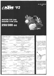
KTM 300 EXC Manual (12 pages)
motor type 546
Brand: KTM
|
Category: Engine
|
Size: 10.69 MB
Table of Contents
-
Technical Data
1
-
Gear Ratios
2
-
Basic Carburetor Setting
2
-
Tolerances and Fitting Clearances
2
-
Gasket Thicknesses
2
-
Crank Case
3
-
Clutch Cover
4
-
Crankshaft, Piston
4
-
Cylinder
5
-
Twin Valve Control
5
-
Carburettor
6
-
Clutch
7
-
Kickstarter
7
-
Ignition System
8
-
Transmission
9
-
Shifting Mechanism
10
-
Cooling System
10
-
Special Tools
11
Advertisement
Related Products
-
KTM 300 EXC AUS
-
KTM 300 EXC EU 2010
-
KTM 300 EXC SIX DAYS EU 2010
-
KTM 300 EXC AUS 2010
-
KTM 300 EXC Six days eu
-
KTM 300 EXC Factory Edition
-
KTM 300 EXC SIX DAYS
-
KTM 300 EXC 2004
-
KTM 300 EXC-E SIX DAYS 2008
-
KTM 300 EXC 2006
KTM Categories
Motorcycle
Motorcycle Accessories
Offroad Vehicle
Engine
Bicycle
More KTM Manuals
Не можете найти ответ на свой вопрос в руководстве? Вы можете найти ответ на свой вопрос ниже, в разделе часто задаваемых вопросов о KTM 300 EXC TPI (2022).
Как перевести мили в километры?
В чем разница между топливом E10 и E5?
Какова рекомендуемая частота замены масляного фильтра в двигателе KTM?
Как часто следует менять масло в двигателе KTM?
Как удалить ржавчину с устройства KTM мотоцикл?
Инструкция KTM 300 EXC TPI (2022) доступно в русский?
Не нашли свой вопрос? Задайте свой вопрос здесь