Kyocera это профессиональная и достаточно дорогая печатная техника, но зато очень качественная, качестве печати у нее выше чем у аналогов так же как и срок службы. Но как и с любой другой возникают различные проблемы. Сегодня рассмотрим одну ситуацию на примере МФУ Kyocera ECOSYS M2135dn. По непонятным причинам МФУ перестает брать бумагу из основного лотка и выдает сообщение о том что бумаги нет, хотя она там конечно же есть. Сообщение выглядят следующим образом «Кассета 1 не загружена» и «Загрузите бумагу в кассету 1». Есть две причины (по крайне мере которые мне известны) которые могут к этому привести, первая это в настройка кто-то поменял устройство подачи по умолчанию и вторая это сломан флажок датчика наличия бумаги в лотке.
M2135dn не берет бумагу с основного лотка
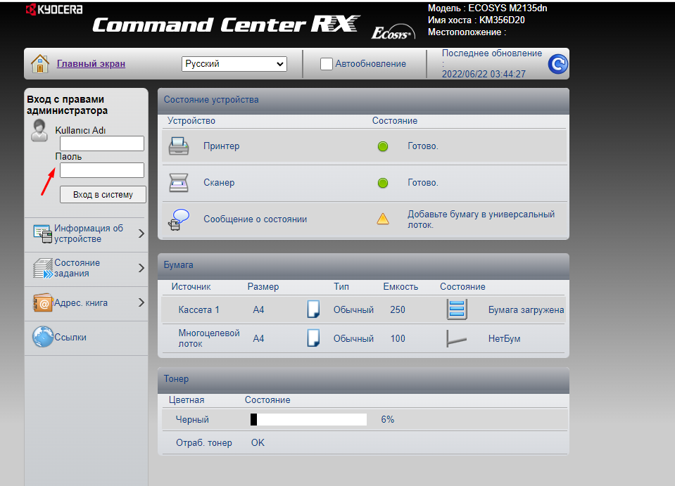
Для начала нужно проверить настройки, сделать это намного проще и удобней через веб интерфейс. Открываем браузер вводим IP адрес принтера далее проходим авторизацию(стандартный логин пароль для этой модели Admin/3500) .
Сервисные пароли Kyocera — https://mita.by/articles/servisnyie-paroli-kyocera/
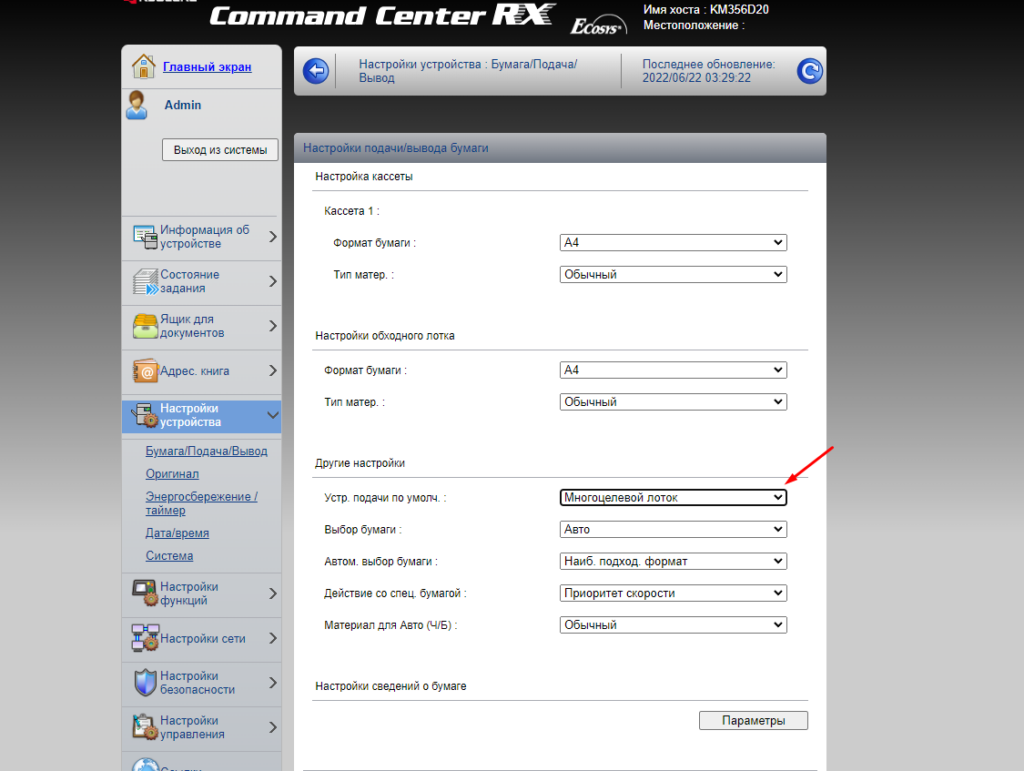
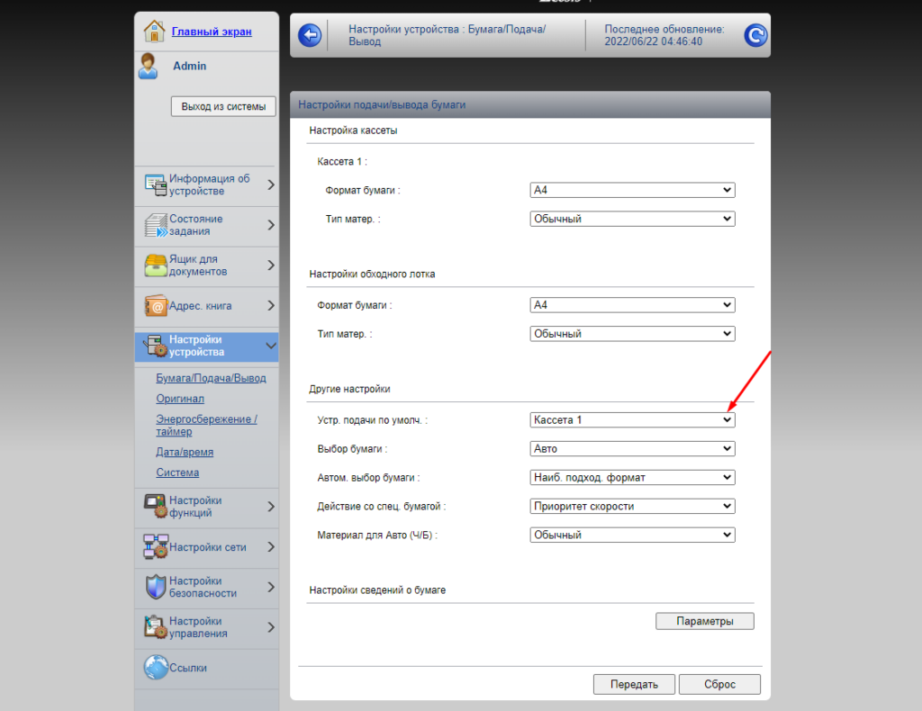
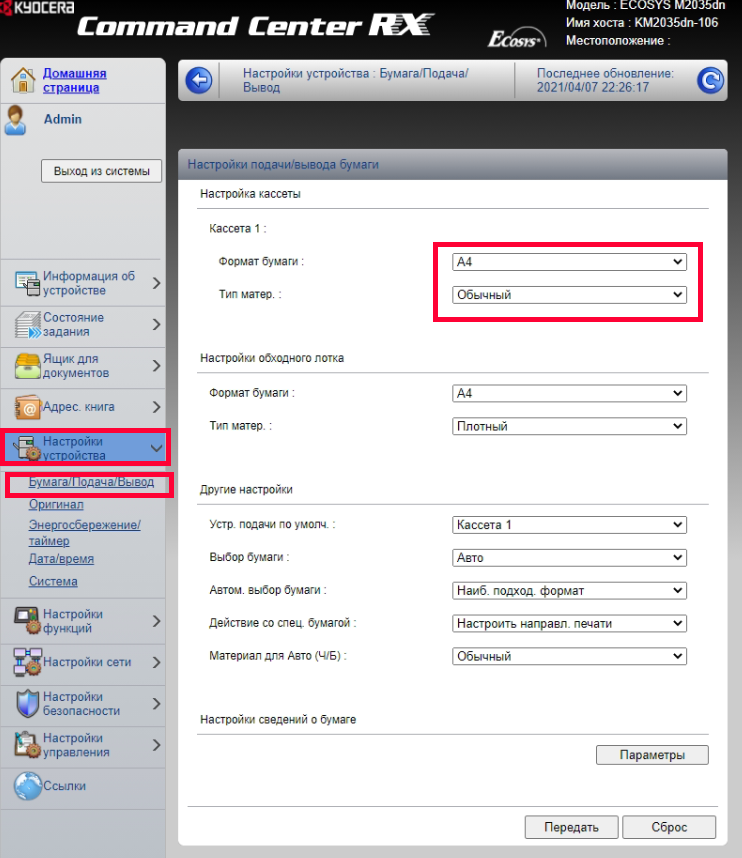
Далее открываем раздел «Настройки» и выбираем пункт «Бумага/Подача/Вывод». В открывшемся окне в пункте «Устр. подачи по умолч» должно стоять «Кассета 1» многоцелевой лоток это лоток ручной подачи.
Изменяем и сохраняем настройки.
Если вы не совсем в этом понимаете или кто-то до вас там что-то непонятное настроил можно вообще сделать сброс до заводских настроек.
Если это не помогло и принтер упорно сообщает о том что в лотке нет бумаги проверяем не сломан ли флажок датчика наличия бумаги. Для этого извлекаем полностью нижний лоток, переворачиваем МФУ на один из боком и смотрим вот на этот флажок.
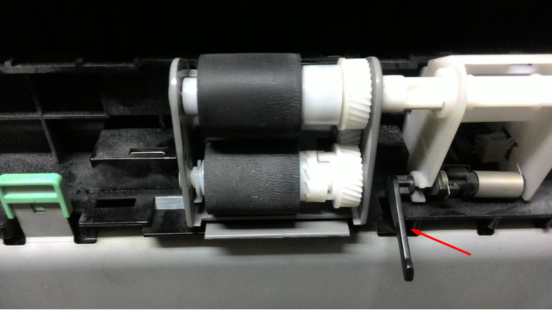
Он может сломаться, либо застрять в приводном валу такое бывает когда вытаскивают застрявшею бумагу, так же с него может слететь пружинка. Если есть неисправности исправляем их, после этого МФУ должно начать работать с вероятностью 95%. Если настройки правильные, флажок на месте но МФУ все равно не печатает то причина в другом. Если у Вас есть другой способ исправить эту ошибку обязательно поделитесь им.
Модератор: vetal

- Вложения
-
-

Foont
- Добрался до абсорбера
-
![]()
![]() Goldwater » Пн апр 19, 2021 4:11 pm
Goldwater » Пн апр 19, 2021 4:11 pm
Последний раз редактировалось Goldwater Пн апр 19, 2021 4:11 pm, всего редактировалось 1 раз.
-

Goldwater
- Избран тонером
-
![]()
![]() Foont » Пн апр 19, 2021 4:22 pm
Foont » Пн апр 19, 2021 4:22 pm


Goldwater писал(а):Явный недочинизм механизма подъёма лотка. Либо лифт, либо шестерня.
имеете в виду, что проблема изначально не только в сломанной оси? ошибку как на фото, выдавал и до замены направляющей.
-
Foont
- Добрался до абсорбера
-
![]()
![]() Foont » Пн апр 19, 2021 4:30 pm
Foont » Пн апр 19, 2021 4:30 pm
-
Foont
- Добрался до абсорбера
-
![]()
![]() Foont » Вт апр 20, 2021 12:45 pm
Foont » Вт апр 20, 2021 12:45 pm
-
Foont
- Добрался до абсорбера
-
![]()
-
- Kyocera FS-1120d индикатор «Нет бумаги»
vs-dos в форуме Принтеры, МФУ, факсы, копиры формата A4
- 11
- 14580
СТРОНЦИЙ

Вт ноя 02, 2021 2:24 pm
- Kyocera FS-1120d индикатор «Нет бумаги»
-
- [SCANNER ERROR] Lamp Error Kyocera FS-1016
мастерчип в форуме Принтеры, МФУ, факсы, копиры формата A4
- 3
- 6436
Усатый Полосатый
Вс окт 28, 2018 11:08 pm
- [SCANNER ERROR] Lamp Error Kyocera FS-1016
-
- Kyocera 1035 «бледная» печать
srMax в форуме Принтеры, МФУ, факсы, копиры формата A4
- 2
- 13544
srMax
Пт янв 23, 2015 2:49 pm
- Kyocera 1035 «бледная» печать
-
- Taskalfa 180 ошибка «Е» и «Встряхните картр. с тонером»
manik.76 в форуме Принтеры, МФУ, копиры формата A3
- 3
- 9189
dviz
Пн фев 20, 2017 1:35 pm
- Taskalfa 180 ошибка «Е» и «Встряхните картр. с тонером»
-
- Стирание вала ведущей шестерни в «печке» Kyocera M2035dn
Грецкий орех в форуме Принтеры, МФУ, факсы, копиры формата A4
- 12
- 2902
СТРОНЦИЙ
Пн дек 13, 2021 3:35 pm
- Стирание вала ведущей шестерни в «печке» Kyocera M2035dn
Вернуться в Принтеры, МФУ, факсы, копиры формата A4
Кто сейчас на форуме
Сейчас этот форум просматривают: нет зарегистрированных пользователей и гости: 131
Иногда ошибка звучит по-другому, «добавьте бумагу в универсальный лоток», но смысл один. Симптом «проблемы» прост. На компьютерах под управлением Windows 10 при попытке отправить на печать любой документ на МФУ, Kyocera выдаёт ошибку. На табло надпись — «вставьте бумагу в универсальный лоток». При этом есть возможность указать другой лоток с бумагой, и тогда документ распечатается, но не бегать же к нему постоянно?
По какой-то причине матёрые приходящие админы в некоторых организациях никак не могут победить эту горе-проблемку. А дело тут просто в источнике бумаги. Дело в том, что универсальный лоток (верхний) у Kyocera потому и универсальный, что способен жрать любую бумагу. Будь то открытки, картон или любой нестандартный размер — все эти форматы Kyocera будет печатать с универсального лотка. А возникающая ошибка лишь говорит нам о том, что с компа на мфу отправлена задача напечатать документ нестандартного размера.
Иногда всё очень просто — например при печате из Word секретарша просто не замечает размер бумаги, что там указан не А4, а, скажем, Letter (письмо). Но чаще всего там стоит верный формат, но Kyocera всё равно пишет «Вставьте бумагу в универсальный лоток».
Решение
Нужно вычислить, в каком именно месте МФУ чётко указано расположение лотка для бумаги, а так же является ли проблема общей, либо такая печать идёт лишь с одного компа.
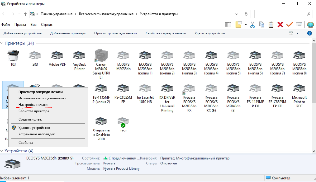
Если kyocera пишет ошибку «Вставьте бумагу в универсальный лоток» только с некоторых АРМ — дело в настройках на них. Первым делом у них следует проверить настройки печати. Для этого идём в панель управления — устройства и принтеры, правый тык на нужной мфу — настройка печати.
В первом же окне, на вкладке «основные» нужно убедиться в двух пунктах.
1. Тип материала для печати — должен быть Обычным, а не цветной бумагой и тд.
2. В качестве источника бумаги по-умолчанию не установлен универсальный лоток.
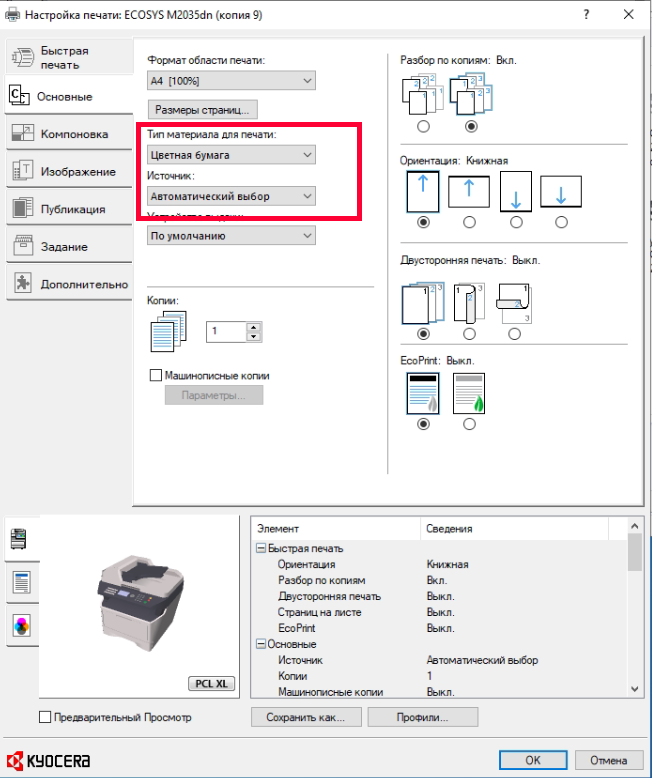
Обычно, на этом всё и заканчивается. Неизвестно почему, но во время штатной установки на некоторые компы драйвер Kyocera KX выставляет там левую бумагу.
Если же проблема наблюдается у любой машины, отправляющей на данную мфу задания по печати — нужно смотреть в конфигурацию самой Kyocera. Для этого идём в веб-часть мфу по её Ip адресу. Быстро узнать IP можно прям с Kyocera, выбрав Системное меню — печать отчёта — строка состояния. Логин и пароль по умолчанию разнятся у разных моделей, у 1135 это admin00, у 2035 — Admin.
Нас интересует пункт настройки устройства — бумага/подача/вывод. Проверьте что для первой касеты установлен тип материала обычный. Такой подвох вам скорее всего оставил бывший админ, либо какие-то шаловливые ручки. Верните настройки на свои места и бухгалтерии перестанут бегать к мфу, а вам скорее всего подарят пивасик.
Выдуманная проблема типа «вставьте бумагу в универсальный лоток» решена.
- Code: 0030
- Description: FAX PWB system error The FAX process can not be continued due to the malfunction of the FAXPWB. *Only 4in1 models detect
- Remedy: FAX PWB 1. Unplug the power cord from the wall outlet, and reinstall the FAX controller PWB, and then plug the power cord and turn power on. 2. Reinstall the FAX firmware. 3. Replace the FAX PWB.
- Code: 0070
- Description: FAX PWB incompatible detection error In the initial communication with the FAX control PWB, any normal communication command is not transmitted. *Only 4in1 models detect
- Remedy: FAX PWB 1. Install the FAX system designed for the model. 2. Reinstall the FAX firmware.
- Code: 0100
- Description: Backup memory device error Outputs an abnormal status from the flash memory.
- Remedy: Flash memory (Main/Engine PWB) 1. Unplug the power cord from the wall outlet, and wait five seconds. Then plug the power cord and then turn on the power switch. 2. Check that the connectors on the Main/ Engine PWB are properly connected, and if not, re-connect them. 3. Replace the Main/Engine PWB.
- Code: 0120
- Description: MAC address data error In case MAC address is invalid data
- Remedy: Flash memory (Main/Engine PWB) 1. Unplug the power cord from the wall outlet, and wait five seconds. Then plug the power cord and then turn on the power switch. 2. Check the MAC address on the network status page. 3. Replace the Main/Engine PWB.
- Code: 0130
- Description: Backup memory read/write error (Main/Engine PWB) Read/write to the NAND memory can not be executed.
- Remedy: Flash memory (Main/Engine PWB) 1. Unplug the power cord from the wall outlet, and wait five seconds. Then plug the power cord and then turn on the power switch. 2. Check that the connectors on the Main/ Engine PWB are properly connected, and if not, re-connect them. 3. Replace the Main/Engine PWB.
- Code: 0140
- Description: Backup memory data error (Main/Engine PWB) At power up, the data that was read from the NAND memory has been determined to be a error.
- Remedy: Flash memory (Main/Engine PWB) 1. Unplug the power cord from the wall outlet, and wait five seconds. Then plug the power cord and then turn on the power switch. 2. Execute U021 initialize memory. 3. Replace the Main/Engine PWB.
- Code: 0150
- Description: EEPROM read/write error (Main/Engine PWB) 1. No response is issued from the device in reading/ writing for 5 ms or more and this problem is repeated 5 times successively. 2. Mismatch of reading data from two locations occurs 8 times successively. 3. Mismatch between writing data and reading data occurs 8 times successively.
- Remedy: EEPROM (Main/ Engine PWB) 1. Unplug the power cord from the wall outlet, and wait five seconds. Then plug the power cord and then turn on the power switch. 2. Check that the EEPROM is peroperly installed on the Main/Engine PWB and if not, reinstall it. 3. Replace the Main/Engine PWB. 4. Check the EEPROM and if it is damaged, contact the service support.
- Code: 0160
- Description: EEPROM data error (Main/ Engine PWB) Reading data from EEPROM is detected abnormal.
- Remedy: EEPROM (Main/ Engine PWB) 1. Unplug the power cord from the wall outlet, and wait five seconds. Then plug the power cord and then turn on the power switch. 2. Execute U021 initialize memory. 3. If the EEPROM data are currupted, contact the service support.
- Code: 0170
- Description: Billing counting error Mismatch between the value of the Main/Engine PWB and EEPROM, in one of the value of billing counter, life counter, or scanner counter.
- Remedy: EEPROM (Main/ Engine PWB) 1. Check that the EEPROM installed in the Main/Engine PWB is correct and, if not, install the correct EEPROM for the model. 2. Replace the Main/Engine PWB. 3. If the EEPROM data are currupted, contact the service support.
- Code: 0180
- Description: Machine number mismatch When the power is turned on, the machine number does not match the one stored in the Main/Engine PWB.
- Remedy: EEPROM (Main/ Engine PWB) 1. Check that the EEPROM installed in the Main/Engine PWB is correct and, if not, install the correct EEPROM for the model. 2. Confirm the serial number data for the Main/Engine PWB by using U004. If the mutually different machine number data between «Machine No. (Main)» and «Machine No. (Eng)» is displayed, or if there is a difference between the actual machine number and the number of «Machine No. (Eng)», install the correct EEPROM, and then execute U004.
- Code: 0190
- Description: Backup memory device error (Main/Engine PWB) At power up, read/write data from FRAM can not be performed. (retry: 3times)
- Remedy: FRAM (Main/ Engine PWB) 1. Unplug the power cord from the wall outlet, and wait five seconds. Then plug the power cord and then turn on the power switch. 2. Check that the connectors on the Main/ Engine PWB are properly connected, and if not, re-connect them. 3. Replace the Main/Engine PWB.
- Code: 0360
- Description: Communication error between the engine ASIC During the readback data checked after data transmission, the checksum error or the video signal is not inverted. (failed 10 consecutive times)
- Remedy: Defective connector cable or poor contact in the connector 1. Reinsert the connector. 2. Check continuity within the connector wire. If none, replace the wire. Engine relay PWB (YC1) and Main/Engine PWB (YC4)
Engine relay PWB Replace the engine relay PWB.
Main/Engine PWB Replace the Main/Engine PWB.
- Code: 0640
- Description: Hard disk (SSD) error During the file access after Ready, the I/O error of SSD is detected. (SSD format error after rebooting. For example, System initialization, Sanitization, Encrypted format when installing security kit.)
- Remedy: SSD (optional HD- 6/7) 1. Unplug the power cord from the wall outlet, and wait five seconds. Then plug the power cord and then turn on the power switch. 2. Unplug the power cord from the wall outlet, and reinstall the HD-6/7 (SSD). 3. Check that the connection between KUIO connector on the Main/Engine PWB and HD-6/7 (SSD) is proper, and if not, re-connect them. 4. Initialize the HD-6/7 (SSD). 5. Replace the Main/Engine PWB.
- Code: 0800
- Description: Image formation problems The printing sequence JAM (J010X) is detected for 2 consecutive times.
- Remedy: Main/Engine PWB 1. Check if the problem is a printing operation error detection in a particular file, and if it is possible to obtain the reproduction of phenomena by the identification of the job that detected the error, take the job log. 2. If the problem occurs in unspecified job, check the connectors on the Main/ Engine PWB, and reattach it. 3. Replace the Main/Engine PWB.
- Code: 0830
- Description: FAX PWB flash program area checksum error The program stored in the flash memory on the FAX control PWB is broken and can not be executed. *Only 4in1 models dete
- Remedy: FAX firmware 1. Reinstall the FAX firmware.
FAX PWB 1. Unplug the power cord from the wall outlet, and reinstall the FAX controller PWB, and then plug the power cord and turn power on. 2. Check that the connection between KUIO connector on the Main/Engine PWB and Fax PWB is proper, and if not, re-connect them. 3. Execute [Initializing] by U600. 4. Replace the FAX PWB.
- Code: 0840
- Description: Faults of RTC Check at power up. The RTC setting has reverted to a previous state. The machine has not been powered for 5 years (compared to the settings stored periodically in the EEPROM). The RTC setting is older than 00:01 on January 1, 2000. Checked periodically (at every 5 minutes) after power-up. The RTC setting has reverted to a state older than the last time it was checked. 10 minutes have been passed since the previous check.
- Remedy: Settings of RTC 1. Execute Date Setting using the system menu.
Backup battery (Main/Engine PWB) 1. Check if the backup battery on the Main/ Engine PWB is not short-circuited. 2. Unplug the power cord from the wall outlet, and wait five seconds. Then plug the power cord and then turn on the power switch. If the same service call error is displayed, replace the backup battery
Main/Engine PWB 1. If the communication error (due to a noise, etc.) is present with the RTC on the Main/Engine PWB, check that the PWB is properly grounded or secured by screws. 2. Replace the Main/Engine PWB.
- Code: 0870
- Description: FAX PWB to Main/Engine PWB image data transfer error High-capacity data transfer between the FAX PWB and the Main/Engine PWB was not normally performed even if the data transfer was retried the specified times. *Only 4in1 models detect
- Remedy: FAX PWB 1. Unplug the power cord from the wall outlet, and reinstall the FAX controller PWB, and then plug the power cord and turn power on. 2. Check that the connection between KUIO connector on the Main/Engine PWB and Fax PWB is proper, and if not, re-connect them. 3. Replace the FAX PWB.
Main/Engine PWB 1. Replace the Main/Engine PWB.
- Code: 0920
- Description: Fax file system error The backup data is not retained for file system abnormality of the flash memory of the FAX PWB. *Only 4in1 models detect
- Remedy: FAX PWB 1. Execute [Initializing] by U600. 2. Reinstall the FAX firmware. 3. Unplug the power cord from the wall outlet, and reinstall the FAX controller PWB, and then plug the power cord and turn power on. 4. Check that the connection between KUIO connector on the Main/Engine PWB and Fax PWB is proper, and if not, re-connect them. 5. Replace the FAX PWB.
- Code: 1010
- Description: Lift motor error (main unit) The following states have been detected 5 times in succession. The lift motor overcurrent is detected for 80 ms. After the cassette is installed, the upper limit detection sensor does not turn ON within 10 s. During printing, after the upper limit detection sensor detects off, and 1 s after ascending control, and the upper limit detection sensor does not detect on. The upper limit detection sensor does not turn off within 5 s after descending control.
- Remedy: Bottom plate 1. Check to see if the bottom plate can move smoothly and repair or replace it if any problem is found.
Defective connector cable or poor contact in the connector 1. Reinsert the connector. 2. If a wire is pinched by other component, or has defect conduction, replace it. Lift motor and Engine relay PWB (YC25) Engine relay PWB (YC1) and Main/Engine PWB (YC4) Llift sensor and Engine relay PWB
Drive transmission system for the lift motor 1. Check if the gears rotate smoothly. If not, clean or grease the bushes and gears. 2. Check broken gears and replace if any.
Lift motor Replace the lift motor.
Lift sensor (upper limit detection sensor) 1. Check if the actuator of the lift sensor can be turned ON/OFF to suit the rise of the cassette bottom plate. 2. Replace the lift sensor
Engine relay PWB 1. Replace the engine relay PWB.
Main/Engine PWB 1. Replace the Main/Engine PWB.
- Code: 1020
- Description: PF lift motor error (PF1) The following states have been detected 5 times in succession. The lift motor overcurrent is detected for 200 ms. After the cassette is installed, the upper limit detection sensor does not turn ON within 10 s. During printing, after the upper limit detection sensor detects off, and 1 s after ascending control, and the upper limit detection sensor does not detect on. The upper limit detection sensor does not turn off within 5 s after descending control.
- Remedy: Bottom plate Check to see if the bottom plate can move smoothly and repair or replace it if any problem is found.
Defective connector cable or poor contact in the connector 1. Reinsert the connector. 2. If a wire is pinched by other component, or has defect conduction, replace it. PF lift motor and PF main PWB (YC7) Llift sensor and PF main PWB (YC7) PF main PWB and Engine relay PWB (YC19)
Drive transmission system for the lift motor 1. Check if the gears rotate smoothly. If not, clean or grease the bushes and gears. 2. Check broken gears and replace if any.
PF lift motor Replace the PF lift motor 1.
PF lift sensor (upper limit detection sensor) 1. Check if the actuator of the PF lift sensor can be turned ON/OFF to suit the rise of the cassette bottom plate. 2. Replace the PF lift sensor.
PF main PWB Replace the PF main PWB.
Engine relay PWB Replace the engine relay PWB.
- Code: 1030
- Description: PF lift motor error (PF2) The following states have been detected 5 times in succession. The lift motor overcurrent is detected for 200 ms. After the cassette is installed, the upper limit detection sensor does not turn ON within 10 s. During printing, after the upper limit detection sensor detects off, and 1 s after ascending control, and the upper limit detection sensor does not detect on. The upper limit detection sensor does not turn off within 5 s after descending control.
- Remedy: Bottom plate Check to see if the bottom plate can move smoothly and repair or replace it if any problem is found.
Defective connector cable or poor contact in the connector 1. Reinsert the connector. 2. If a wire is pinched by other component, or has defect conduction, replace it. PF lift motor and PF main PWB (YC7) Llift sensor and PF main PWB (YC7) PF main PWB and Engine relay PWB (YC19)
Drive transmission system for the lift motor 1. Check if the gears rotate smoothly. If not, clean or grease the bushes and gears. 2. Check broken gears and replace if any.
PF lift motor Replace the PF lift motor 2.
PF lift sensor (upper limit detection sensor) 1. Check if the actuator of the PF lift sensor can be turned ON/OFF to suit the rise of the cassette bottom plate. 2. Replace the PF lift sensor.
PF main PWB Replace the PF main PWB.
Engine relay PWB Replace the engine relay PWB.
- Code: 1040
- Description: PF lift motor error (PF3) The following states have been detected 5 times in succession. The lift motor overcurrent is detected for 200 ms. After the cassette is installed, the upper limit detection sensor does not turn ON within 10 s. During printing, after the upper limit detection sensor detects off, and 1 s after ascending control, and the upper limit detection sensor does not detect on. The upper limit detection sensor does not turn off within 5 s after descending control.
- Remedy: Bottom plate Check to see if the bottom plate can move smoothly and repair or replace it if any problem is found.
Defective connector cable or poor contact in the connector 1. Reinsert the connector. 2. If a wire is pinched by other component, or has defect conduction, replace it. PF lift motor and PF main PWB (YC7) Llift sensor and PF main PWB (YC7) PF main PWB and Engine relay PWB (YC19)
Drive transmission system for the lift motor 1. Check if the gears rotate smoothly. If not, clean or grease the bushes and gears. 2. Check broken gears and replace if any.
PF lift motor Replace the PF lift motor.
PF lift sensor (upper limit detection sensor) 1. Check if the actuator of the PF lift sensor can be turned ON/OFF to suit the rise of the cassette bottom plate. 2. Replace the PF lift sensor.
PF main PWB Replace the PF main PWB.
Engine relay PWB Replace the engine relay PWB.
- Code: 1810
- Description: Paper feeder communication error (first cassette) A communication error from paper feeder is detected 10 times in succession.
- Remedy: Paper feeder 1 Check the wiring connection status with the main unit, and if necessary, reconnecting it.
PF1 main PWB 1. Confirm that the wiring connector is firmly connected, and if necessary, connect the connector all the way in. PF1 main PWB (YC3 and Engine relay PWB (YC19) 2. If the wiring is disconnected, short-circuited or has ground fault, replace the wire. 3. Reinstall the PF firmware. 4. Replace the PF main PWB. (Refer to the service manual for the paper feeder).
Engine relay PWB 1. Replace the engine relay PWB.
Main/Engine PWB 1. Check the engine firmware and upgrade to the latest version if necessary. 2. Replace the Main/Engine PWB.
- Code: 1820
- Description: Paper feeder communication error (second cassette) A communication error from paper feeder is detected 10 times in succession.
- Remedy: Paper feeder 2 Check the wiring connection status with PF1, and if necessary, reconnect it.
PF2 main PWB 1. Confirm that the wiring connector is firmly connected, and if necessary, connect the connector all the way in. PF1 main PWB (YC3)and PF2 main PWB (YC5,4) 2. If the wiring is disconnected, short-circuited or has ground fault, replace the wire. 3. Reinstall the PF firmware. 4. Replace the PF2 main PWB.
PF1 main PWB Replace the PF1 main PWB.
- Code: 1830
- Description: Paper feeder communication error (third cassette) A communication error from paper feeder is detected 10 times in succession.
- Remedy: Paper feeder 3 Check the wiring connection status with PF2, and if necessary, reconnect it.
PF3 main PWB 1. Confirm that the wiring connector is firmly connected, and if necessary, connect the connector all the way in. PF2 main PWB (YC3 and PF3 main PWB (YC5,4) 2. If the wiring is disconnected, short-circuited or has ground fault, replace the wire. 3. Reinstall the PF firmware. 4. Replace the PF3 main PWB.
PF2 main PWB Replace the PF2 main PWB.
- Code: 1900
- Description: Paper feeder 1 EEPROM error (first cassette) When writing the data, read and write data does not match 4 times in succession.
- Remedy: PF1 main PWB (EEPROM) 1. Unplug the power cord from the wall outlet, and wait five seconds. Then plug the power cord and then turn on the power switch. 2. Confirm that the wiring connector to the main unit is firmly connected, and if necessary, connect the connector all the way in. 3. Replace the PF1 main PWB.
- Code: 1910
- Description: Paper feeder 2 EEPROM error (second cassette) When writing the data, read and write data does not match 4 times in succession.
- Remedy: PF2 main PWB (EEPROM) 1. Unplug the power cord from the wall outlet, and wait five seconds. Then plug the power cord and then turn on the power switch. 2. Confirm that the wiring connector with the PF1 is firmly connected, and if necessary, connect the connector all the way in. 3. Replace the PF2 main PWB.
- Code: 1920
- Description: Paper feeder 3 EEPROM error (third cassette) When writing the data, read and write data does not match 4 times in succession.
- Remedy: PF3 main PWB 1. Unplug the power cord from the wall outlet, and wait five seconds. Then plug the power cord and then turn on the power switch. 2. Confirm that the wiring connector with the PF2 is firmly connected, and if necessary, connect the connector all the way in. 3. Replace the PF3 main PWB.
- Code: 2101
- Description: Developer motor steadystate error (C,M,Y) After motor is stabilized, the stable signal is turned OFF for continuous 2 s.
- Remedy: Developer unit 1. Check that the developer roller can be rotated by hand, and if it is locked, replace the developer unit.
Developer motor 1. Check if the couplings and gears rotate smoothly, and if necessary replace them. 2. Reinsert the connector. 3. Check continuity within the connector wire. If none, replace the wire. Developer motor and Engine relay PWB (YC12) Engine relay PWB (YC1) and Main/ Engine PWB (YC4) 4. Replace the developer motor
Engine relay PWB Replace the engine relay PWB.
Main/Engine PWB 1. Check the engine firmware and upgrade to the latest version if necessary. 2. Replace the Main/Engine PWB.
- Code: 2111
- Description: Developer motor startup error (C,M,Y) After the motor starting, the stable signal is not turned ON within 3 s.
- Remedy: Developer unit 1. Check that the developer roller can be rotated by hand, and if it is locked, replace the developer unit.
Developer motor 1. Check if the couplings and gears rotate smoothly, and if necessary replace them. 2. Reinsert the connector. 3. Check continuity within the connector wire. If none, replace the wire. Developer motor and Engine relay PWB (YC12) Engine relay PWB (YC1) and Main/ Engine PWB (YC4) 4. Replace the developer motor
Engine relay PWB Replace the engine relay PWB.
Main/Engine PWB 1. Check the engine firmware and upgrade to the latest version if necessary. 2. Replace the Main/Engine PWB.
- Code: 2201
- Description: Drum motor CY steadystate error After motor is stabilized, the stable signal is turned OFF for continuous 2 s.
- Remedy: Drum unit C or Drum unit Y Check that the drum can be rotated by hand, and if it is locked, replace the drum unit C or drum unit Y.
Defective connector cable or poor contact in the connector 1. Reinsert the connector. 2. Check continuity within the connector wire. If none, replace the wire. Drum motor CY and Engine relay PWB (YC13) Engine relay PWB (YC1) and Main/Engine PWB (YC4)
Drive transmission system for the drum motor CY 1. Check if the couplings and gears rotate smoothly, and if not, clean or grease the gears. 2. Check broken couplings and gears, and replace if any.
Drum motor CY Replace the drum motor CY.
Engine relay PWB Replace the engine relay PWB.
Main/Engine PWB Replace the Main/Engine PWB.
- Code: 2202
- Description: Drum motor KM steadystate error After motor is stabilized, the stable signal is turned OFF for continuous 2 s.
- Remedy: Drum unit K or Drum unit M Check that the drum can be rotated by hand, and if it is locked, replace the drum unit K or drum unit M.
Defective connector cable or poor contact in the connector 1. Reinsert the connector. 2. Check continuity within the connector wire. If none, replace the wire. Drum motor KM and Engine relay PWB (YC13) Engine relay PWB (YC1) and Main/Engine PWB (YC4)
Drive transmission system for the drum motor KM 1. Check if the couplings and gears rotate smoothly, and if not, clean or grease the gears. 2. Check broken couplings and gears, and replace if any.
Drum motor KM Replace the drum motor KM.
Engine relay PWB Replace the engine relay PWB.
Main/Engine PWB Replace the Main/Engine PWB.
- Code: 2211
- Description: Drum motor CY startup error After the motor starting, the stable signal is not turned ON within 3 s.
- Remedy: Drum unit C or Drum unit Y Check that the drum can be rotated by hand, and if it is locked, replace the drum unit C or drum unit Y.
Defective connector cable or poor contact in the connector 1. Reinsert the connector. 2. Check continuity within the connector wire. If none, replace the wire. Drum motor CY and Engine relay PWB (YC13) Engine relay PWB (YC1) and Main/Engine PWB (YC4)
Drive transmission system for the drum motor CY 1. Check if the couplings and gears rotate smoothly, and if not, clean or grease the gears. 2. Check broken couplings and gears, and replace if any.
Drum motor CY Replace the drum motor CY.
Engine relay PWB Replace the engine relay PWB.
Main/Engine PWB Replace the Main/Engine PWB.
- Code: 2212
- Description: Drum motor KM startup error After the motor starting, the stable signal is not turned ON within 3 s.
- Remedy: Drum unit K or Drum unit M Check that the drum can be rotated by hand, and if it is locked, replace the drum unit K or drum unit M.
Defective connector cable or poor contact in the connector 1. Reinsert the connector. 2. Check continuity within the connector wire. If none, replace the wire. Drum motor KM and Engine relay PWB (YC13) Engine relay PWB (YC1) and Main/Engine PWB (YC4)
Drive transmission system for the drum motor KM 1. Check if the couplings and gears rotate smoothly, and if not, clean or grease the gears. 2. Check broken couplings and gears, and replace if any.
Drum motor KM Replace the drum motor KM.
Engine relay PWB Replace the engine relay PWB.
Main/Engine PWB Replace the Main/Engine PWB.
- Code: 2500
- Description: Paper feed motor error After the motor starting, the stable signal is not turned ON within 3 s. After motor is stabilized, the stable signal is turned OFF for continuous 2 s.
- Remedy: Defective connector cable or poor contact in the connector 1. Reinsert the connector. 2. Check continuity within the connector wire. If none, replace the wire. Paper feed motor and Engine relay PWB (YC15) Engine relay PWB (YC1) and Main/Engine PWB (YC4)
Drive transmission system for the paper feed motor 1. Check if the rollers and gears rotate smoothly. If not, clean or grease the bushes and gears. 2. Replace the gears, if damaged.
Paper feed motor Replace the paper feed motor.
Engine relay PWB Replace the engine relay PWB.
Main/Engine PWB Replace the Main/Engine PWB.
- Code: 2600
- Description: PF drive motor 1 error (PF1) During the motor drive, the stable signal is not turned on for continuous 5 s.
- Remedy: Defective connector cable or poor contact in the connector 1. Reinsert the connector. 2. Check continuity within the connector wire. If none, replace the wire. PF drive motor 1 and PF main PWB (YC6)
Drive transmission system for the PF drive motor 1. Check if the rollers and gears rotate smoothly. If not, clean or grease the bushes and gears. 2. Replace the gears, if damaged.
PF drive motor Replace the PF drive motor 1.
PF main PWB Replace the PF main PWB.
- Code: 2610
- Description: PF drive motor 2 error (PF2) During the motor drive, the stable signal is not turned on for continuous 5 s.
- Remedy: Defective connector cable or poor contact in the connector 1. Reinsert the connector. 2. Check continuity within the connector wire. If none, replace the wire. PF drive motor 2 and PF main PWB (YC6)
Drive transmission system for the PF drive motor 1. Check if the rollers and gears rotate smoothly. If not, clean or grease the bushes and gears. 2. Replace the gears, if damaged.
PF drive motor Replace the PF drive motor 2.
PF main PWB Replace the PF main PWB.
- Code: 2620
- Description: PF drive motor 3 error (PF3) During the motor drive, the stable signal is not turned on for continuous 5 s.
- Remedy: Defective connector cable or poor contact in the connector 1. Reinsert the connector. 2. Check continuity within the connector wire. If none, replace the wire. PF drive motor 3 and PF main PWB (YC6)
Drive transmission system for the PF drive motor 1. Check if the rollers and gears rotate smoothly. If not, clean or grease the bushes and gears. 2. Replace the gears, if damaged.
PF drive motor Replace the PF drive motor 3.
PF main PWB Replace the PF main PWB.
- Code: 2760
- Description: Primary transfer belt motor startup error After the motor starting, the stable signal is not turned ON within 3 s.
- Remedy: Primary transfer unit 1. Check that the belt can be rotated by hand, and if it is locked, get rid of the factor. 2. Replace the primary transfer unit.
Defective connector cable or poor contact in the connector 1. Reinsert the connector. 2. Check continuity within the connector wire. If none, replace the wire. Transfer belt motor and Engine relay PWB (YC14) Engine relay PWB (YC1) and Main/Engine PWB (YC4)
Drive transmission system for the primary transfer belt motor 1. Check if the rollers and gears rotate smoothly. If not, clean or grease the bushes and gears. 2. Replace the gears, if damaged.
Primary transfer belt motor Replace the primary transfer belt motor.
Engine relay PWB Replace the engine relay PWB.
Main/Engine PWB Replace the Main/Engine PWB.
- Code: 2820
- Description: Primary transfer belt motor steady-state error After motor is stabilized, the stable signal is turned OFF for continuous 2 s.
- Remedy: Primary transfer unit 1. Check that the belt can be rotated by hand, and if it is locked, check if foreign objects such as jammed paper, and if jammed, get rid of it. 2. Replace the primary transfer unit.
Defective connector cable or poor contact in the connector 1. Reinsert the connector. 2. Check continuity within the connector wire. If none, replace the wire. Transfer belt motor and Engine relay PWB (YC14) Engine relay PWB (YC1) and Main/Engine PWB (YC4)
Drive transmission system for the primary transfer belt motor 1. Check if the rollers and gears rotate smoothly. If not, clean or grease the bushes and gears. 2. Replace the gears, if damaged.
Primary transfer belt motor Replace the primary transfer belt motor.
Engine relay PWB Replace the engine relay PWB.
Main/Engine PWB Replace the Main/Engine PWB.
- Code: 3100
- Description: Scanner carriage error When turning the power on, or when the reading of the original document by table or DP scanning has completed, the home position sensor is not turned off, even if the home position sensor is on and the scanner carriage moves to the scanning direction. Or, the home position sensor does not turn on, even if the home position sensor is in off and the scanner carriage move to the return direction.
- Remedy: Image scanner motor 1. Move the scanner by hand to check whether it smoothly moves, and if necessary, remedy it. 2. Check that the scanner drive belt is not disengaged, and if necessary, remedy it. 3. Confirm that the wiring connector is firmly connected, and if necessary, connect the connector all the way in. Image scanner motor and Main/Engine PWB (YC17) 4. If the wiring is disconnected, short-circuited or has ground fault, replace the wire. 5. Replace the image scanner motor.
Home position sensor 1. Check that the sensor is correctly positioned. 2. Confirm that the wiring connector is firmly connected, and if necessary, connect the connector all the way in. Home position sensor and CCD PWB (YC3) CCD PWB (YC1) and Main/Engine PWB (YC2014) 3. Replace the home position sensor.
CCD PWB Replace the scanner carriage and execute the U411.
Main/Engine PWB Replace the Main/Engine PWB.
- Code: 3200
- Description: LED lamp error The white standard data obtained when the lamp is turned on at the time of an initialization is lower than the rated value.
- Remedy: LED PWB 1. Confirm that the wiring connector is firmly connected, and if necessary, connect the connector all the way in. LED PWB and CCD PWB (YC2) CCD PWB (YC1) and Main/Engine PWB (YC2014)
Mirror Replace the image scanner unit and execute U411, if the mirror is dropped off by drop shock.
CCD PWB Replace the scanner carriage and execute the U411.
Main/Engine PWB Replace the Main/Engine PWB.
- Code: 3500
- Description: Communication error between scanner ASIC (MFP model only) A communication error is detected. (Read back values are different.)
- Remedy: CCD PWB 1. Confirm that the wiring connector is firmly connected, and if necessary, connect the connector all the way in. CCD PWB (YC1) and Main/Engine PWB (YC2014) 2. If the wiring is disconnected, short-circuited or has ground fault, replace the wire. 3. Replace the scanner carriage and execute the U411.
Main/Engine PWB 1. Upgrade the scanner firmware to the latest version. 2. Replace the Main/Engine PWB.
- Code: 4001
- Description: Polygon motor (Black, Magenta) startup error After the polygon motor starting, the motor stable signal is not turned ON after 6 s.
- Remedy: Polygon motor (Black, Magenta) 1. Confirm that the wiring connector is firmly connected, and if necessary, connect the connector all the way in. LSU and Main/Engine PBW (YC2016) 2. If the wiring is disconnected, short-circuited or has ground fault, replace the wire. 3. Replace the LSU.
Main/Engine PWB 1. Check the engine firmware and upgrade to the latest version if necessary. 2. Replace the Main/Engine PWB.
- Code: 4002
- Description: Polygon motor (Cyan, Yellow) startup error After the polygon motor starting, the motor stable signal is not turned ON after 6 s.
- Remedy: Polygon motor (Cyan, Yellow) 1. Confirm that the wiring connector is firmly connected, and if necessary, connect the connector all the way in. LSU and Main/Engine PBW (YC2017) 2. If the wiring is disconnected, short-circuited or has ground fault, replace the wire. 3. Replace the LSU.
Main/Engine PWB 1. Check the engine firmware and upgrade to the latest version if necessary. 2. Replace the Main/Engine PWB.
- Code: 4011
- Description: Polygon motor (Black, Magenta) steady error After the polygon motor stabilization, the motor stable signal is turned OFF for consecutive 6 s.
- Remedy: Polygon motor (Black, Magenta) 1. Confirm that the wiring connector is firmly connected, and if necessary, connect the connector all the way in. LSU and Main/Engine PBW (YC2016) 2. If the wiring is disconnected, short-circuited or has ground fault, replace the wire. 3. Replace the LSU.
Main/Engine PWB 1. Check the engine firmware and upgrade to the latest version if necessary. 2. Replace the Main/Engine PWB.
- Code: 4012
- Description: Polygon motor (Cyan, Yellow) steady error After the polygon motor stabilization, the motor stable signal is turned OFF for consecutive 6 s.
- Remedy: Polygon motor (Cyan, Yellow) 1. Confirm that the wiring connector is firmly connected, and if necessary, connect the connector all the way in. LSU and Main/Engine PBW (YC2017) 2. If the wiring is disconnected, short-circuited or has ground fault, replace the wire. 3. Replace the LSU.
Main/Engine PWB 1. Check the engine firmware and upgrade to the latest version if necessary. 2. Replace the Main/Engine PWB.
- Code: 4101
- Description: Laser BD (Black) error The laser can not be received for 1 s, after the Black laser emission starts.
- Remedy: LSU (Black,Magenta) 1. Confirm that the wiring connector is firmly connected, and if necessary, connect the connector all the way in. LSU and Main/Engine PBW (YC2016) 2. If the wiring is disconnected, short-circuited or has ground fault, replace the wire. 3. Replace the LSU.
Main/Engine PWB 1. Check both main and engine firmware, and upgrade to the latest version, if necessary. 2. Replace the Main/Engine PWB.
- Code: 4102
- Description: Laser BD (Cyan) error The laser can not be received for 1 s, after the Cyan laser emission starts.
- Remedy: LSU (Cyan, Yellow) 1. Confirm that the wiring connector is firmly connected, and if necessary, connect the connector all the way in. LSU and Main/Engine PBW (YC2017) 2. If the wiring is disconnected, short-circuited or has ground fault, replace the wire. 3. Replace the LSU.
Main/Engine PWB 1. Check both main and engine firmware, and upgrade to the latest version, if necessary. 2. Replace the Main/Engine PWB.
- Code: 4103
- Description: Laser BD (Magenta) error The laser can not be received for 1 s, after the Magenta laser emission starts.
- Remedy: LSU (Black,Magenta) 1. Confirm that the wiring connector is firmly connected, and if necessary, connect the connector all the way in. LSU and Main/Engine PBW (YC2016) 2. If the wiring is disconnected, short-circuited or has ground fault, replace the wire. 3. Replace the LSU.
Main/Engine PWB 1. Check both main and engine firmware, and upgrade to the latest version, if necessary. 2. Replace the Main/Engine PWB.
- Code: 4104
- Description: Laser BD (Yellow) error The laser can not be received for 1 s, after the Yellow laser emission starts.
- Remedy: LSU (Cyan, Yellow) 1. Confirm that the wiring connector is firmly connected, and if necessary, connect the connector all the way in. LSU and Main/Engine PBW (YC2017) 2. If the wiring is disconnected, short-circuited or has ground fault, replace the wire. 3. Replace the LSU.
Main/Engine PWB 1. Check both main and engine firmware, and upgrade to the latest version, if necessary. 2. Replace the Main/Engine PWB.
- Code: 4201
- Description: Laser BD (Black) steadystate error During the polygon motor steady rotation, the BD signal of Black is not detected.
- Remedy: LSU (Black,Magenta) 1. Confirm that the wiring connector is firmly connected, and if necessary, connect the connector all the way in. LSU and Main/Engine PBW (YC2016) 2. If the wiring is disconnected, short-circuited or has ground fault, replace the wire. 3. Replace the LSU.
Main/Engine PWB 1. Check both main and engine firmware, and upgrade to the latest version, if necessary. 2. Replace the Main/Engine PWB.
- Code: 4202
- Description: Laser BD (Cyan) steadystate error During the polygon motor steady rotation, the BD signal of Cyan is not detected.
- Remedy: LSU (Cyan,Yellow) 1. Confirm that the wiring connector is firmly connected, and if necessary, connect the connector all the way in. LSU and Main/Engine PBW (YC2017) 2. If the wiring is disconnected, short-circuited or has ground fault, replace the wire. 3. Replace the LSU.
Main/Engine PWB 1. Check both main and engine firmware, and upgrade to the latest version, if necessary. 2. Replace the Main/Engine PWB.
- Code: 4203
- Description: Laser BD (Magenta) steadystate error During the polygon motor steady rotation, the BD signal of Magenta is not detected.
- Remedy: LSU (Black,Magenta) 1. Confirm that the wiring connector is firmly connected, and if necessary, connect the connector all the way in. LSU and Main/Engine PBW (YC2016) 2. If the wiring is disconnected, short-circuited or has ground fault, replace the wire. 3. Replace the LSU.
Main/Engine PWB 1. Check both main and engine firmware, and upgrade to the latest version, if necessary. 2. Replace the Main/Engine PWB.
- Code: 4204
- Description: Laser BD (Yellow) steadystate error During the polygon motor steady rotation, the BD signal of Yellow is not detected.
- Remedy: LSU (Cyan,Yellow) 1. Confirm that the wiring connector is firmly connected, and if necessary, connect the connector all the way in. LSU and Main/Engine PBW (YC2017) 2. If the wiring is disconnected, short-circuited or has ground fault, replace the wire. 3. Replace the LSU.
Main/Engine PWB 1. Check both main and engine firmware, and upgrade to the latest version, if necessary. 2. Replace the Main/Engine PWB.
- Code: 4600
- Description: LSU cleaning motor error During driving the LSU cleaning motor, an over-current is detected for 5 s successively
- Remedy: LSU cleaning spiral 1. Execute [LSU cleaning] using [Adjustment/ Maintenance] of the system menu. 2. Check that the drive gear and cleaning spiral can rotate and they are not unusually loaded, and if necessary, clean and grease.
LSU cleaning motor 1. Confirm that the LSU cleaning motor has been firmly attached. 2. Replace the LSU cleaning motor.
Engine relay PWB 1. Reconnect the connector if its connection is loose. 2. If a wire is pinched by other component, or has defect conduction, replace it. LSU cleaning motor and Engine relay PWB (YC26) 3. Replace the engine relay PWB.
- Code: 4700
- Description: VIDEO_ASIC device error Communication with the video ASIC has failed 5 times successively. After writing to VIDEO ASIC, the error that the reading value from same address does not match occurs 8 times successively.
- Remedy: Main/Engine PWB 1. Unplug the power cord from the wall outlet, and wait five seconds. Then plug the power cord and then turn on the power switch. 2. Check that the connectors on the Main/ Engine PWB are properly connected, and if not, re-connect them. 3. Replace the Main/Engine PWB.
- Code: 6000
- Description: Broken fuser main heater wire During the warming up, the temperature detected by the center thermistor does not reach 100 °C/212.0 °F for 20 s. During the warming up, the temperature detected by the center thermistor does not reach the stable display temperature for 30 s successively, after it reach to 100 °C/212.0 °F.
- Remedy: Fuser unit 1. Check there is no paper jam. 2. Confirm that the wiring connector is firmly connected, and if necessary, connect the connector all the way in. Fuser unit and Eject PWB (YC2) Eject PWB (YC1) and Main/Engine PWB (YC11) 3. If the wiring is disconnected, short-circuited or has ground fault, replace the wire. 4. If the fuser heater is not turned on (broken thermostat wire), replace the fuser unit.
Power source PWB 1. Confirm that the wiring connector is firmly connected, and if necessary, connect the connector all the way in. Power source PWB (YC105) and Main/ Engine PWB (YC20) 2. Replace the power source PWB.
Eject PWB Replace the eject PWB.
Main/Engine PWB 1. Check the engine firmware and upgrade to the latest version if necessary. 2. Replace the Main/Engine PWB.
- Code: 6020
- Description: Abnormally high fuser center thermistor temperature The center thermistor detected the temperature exceeds 240 °C/464.0 °F. for 1 s successively.
- Remedy: Fuser unit 1. Check there is no paper jam. 2. Check if the fuser roller has foreign objects such as the toner contamination. 3. Confirm that the wiring connector is firmly connected, and if necessary, connect the connector all the way in. Fuser unit and Eject PWB (YC2) Eject PWB (YC1) and Main/Engine PWB (YC11) 4. If the wiring is disconnected, short-circuited or has ground fault, replace the wire. 5. Replace the fuser unit.
Power source PWB 1. Confirm that the wiring connector is firmly connected, and if necessary, connect the connector all the way in. Power source PWB (YC105) and Main/ Engine PWB (YC20) 2. If the fuser heater is turned on at all times, replace the power source PWB.
Main/Engine PWB 1. Check the engine firmware and upgrade to the latest version if necessary. 2. Check if the Main/Engine PWB is properly secured with screws. 3. Replace the Main/Engine PWB.
- Code: 6030
- Description: Broken fuser center thermistor wire During the edge thermistor detects more than 30 °C/86.0 °F, the center thermistor detects low temperature for 1.6 s.
- Remedy: Fuser unit 1. Check there is no paper jam. 2. Confirm that the wiring connector is firmly connected, and if necessary, connect the connector all the way in. Fuser unit and Eject PWB (YC2) Eject PWB (YC1) and Main/Engine PWB (YC11) 3. If the wiring is disconnected, short-circuited or has ground fault, replace the wire. 4. Replace the fuser unit.
Eject PWB Replace the eject PWB.
Main/Engine PWB 1. Check the engine firmware and upgrade to the latest version if necessary. 2. Replace the Main/Engine PWB.
- Code: 6040
- Description: Fuser heater error (35 ppm models) Input value from the fuser center thermistor is abnormal for 1 s successively.
- Remedy: Fuser unit 1. Check there is no paper jam. 2. Confirm that the wiring connector is firmly connected, and if necessary, connect the connector all the way in. Fuser unit and Eject PWB (YC2) Eject PWB (YC1) and Main/Engine PWB (YC11) 3. If the wiring is disconnected, short-circuited or has ground fault, replace the wire. 4. Replace the fuser unit.
Eject Main/Engine PWB 1. Check the engine firmware and upgrade to the latest version if necessary. 2. Replace the Main/Engine PWB.PWB Replace the eject PWB.
- Code: 6050
- Description: Abnormally low fuser center thermistor temperature During the warming up and the printing, the center thermistor has detected less than 100 °C/212.0 °F. for 1 s successively.
- Remedy: Reduction of the power supply voltage 1. Check that no voltage drop of more than 10% of the rated is caused during printing. 2. If the power is overloaded, change the AC outlet that supplies power.
Fuser unit 1. Check there is no paper jam. 2. Confirm that the wiring connector is firmly connected, and if necessary, connect the connector all the way in. Fuser unit and Eject PWB (YC2) Eject PWB (YC1) and Main/Engine PWB (YC11) 3. If the wiring is disconnected, short-circuited or has ground fault, replace the wire. 4. If the fuser heater is not turned on (broken thermostat wire), replace the fuser unit.
Power source PWB 1. Confirm that the wiring connector is firmly connected, and if necessary, connect the connector all the way in. Power source PWB (YC105) and Main/ Engine PWB (YC20) 2. Replace the power source PWB.
Eject PWB Replace the eject PWB.
Main/Engine PWB 1. Check the engine firmware and upgrade to the latest version if necessary. 2. Replace the Main/Engine PWB.
- Code: 6200
- Description: Fuser heater error (SUb heater: for 35ppm models) During the warming up, even if the main heater (sub heater for 35ppm models) is turned on for 30 s successively, the temperature detected by the edge thermistor does not reach 100 °C/212.0 °F. During the warming up, the temperature detected by the edge thermistor does not reach the stable display temperature, even if the main heater (sub heater for 35ppm models) is turned on for 30 s successively, after the temperature detected by the edge thermistor has reached to 100 °C/212.0 °F.
- Remedy: Fuser unit 1. Check there is no paper jam. 2. Confirm that the wiring connector is firmly connected, and if necessary, connect the connector all the way in. Fuser unit and Eject PWB (YC2) Eject PWB (YC1) and Main/Engine PWB (YC11) 3. If the wiring is disconnected, short-circuited or has ground fault, replace the wire. 4. If the fuser sub-heater is not turned on (broken thermostat wire), replace the fuser unit.
Power source PWB 1. Confirm that the wiring connector is firmly connected, and if necessary, connect the connector all the way in. Power source PWB (YC105) and Main/ Engine PWB (YC20) 2. Replace the power source PWB.
Eject PWB Replace the eject PWB.
Main/Engine PWB 1. Check the engine firmware and upgrade to the latest version if necessary. 2. Replace the Main/Engine PWB.
- Code: 6220
- Description: Abnormally high fuser heater temperature The temperature detected by the edge thermistor exceeds 240 °C/464.0 °F for 1 s successively.
- Remedy: Fuser unit 1. Check there is no paper jam. 2. Check if the fuser roller has foreign objects such as the toner contamination. 3. Confirm that the wiring connector is firmly connected, and if necessary, connect the connector all the way in. Fuser unit and Eject PWB (YC2) Eject PWB (YC1) and Main/Engine PWB (YC11) 4. If the wiring is disconnected, short-circuited or has ground fault, replace the wire. 5. Replace the fuser unit.
Power source PWB 1. Confirm that the wiring connector is firmly connected, and if necessary, connect the connector all the way in. Power source PWB (YC105) and Main/ Engine PWB (YC20) 2. If the fuser heater is turned on at all times, replace the power source PWB.
Main/Engine PWB 1. Check the engine firmware and upgrade to the latest version if necessary. 2. Check if the Main/Engine PWB is properly secured with screws. 3. Replace the Main/Engine PWB.
- Code: 6230
- Description: Broken fuser edge thermistor wire Fuser edge thermistor detects low temperature for 1.6 s.
- Remedy: Fuser unit 1. Check there is no paper jam. 2. Confirm that the wiring connector is firmly connected, and if necessary, connect the connector all the way in. Fuser unit and Eject PWB (YC2) Eject PWB (YC1) and Main/Engine PWB (YC11) 3. If the wiring is disconnected, short-circuited or has ground fault, replace the wire. 4. Replace the fuser unit.
Eject PWB Replace the eject PWB.
Main/Engine PWB 1. Check the engine firmware and upgrade to the latest version if necessary. 2. Replace the Main/Engine PWB.
- Code: 6250
- Description: Abnormally low fuser edge thermistor temperature During the warming up and the printing, the edge thermistor has detected less than 100 °C/212.0 °F for 1 s successively.
- Remedy: Reduction of the power supply voltage 1. Check that no voltage drop of more than 10% of the rated is caused during printing. 2. If the power is overloaded, change the AC outlet that supplies power.
Fuser unit 1. Check there is no paper jam. 2. Confirm that the wiring connector is firmly connected, and if necessary, connect the connector all the way in. Fuser unit and Eject PWB (YC2) Eject PWB (YC1) and Main/Engine PWB (YC11) 3. If the wiring is disconnected, short-circuited or has ground fault, replace the wire. 4. If the fuser heater is not turned on (broken thermostat wire), replace the fuser unit.
Power source PWB 1. Confirm that the wiring connector is firmly connected, and if necessary, connect the connector all the way in. Power source PWB (YC105) and Main/ Engine PWB (YC20) 2. Replace the power source PWB.
Eject PWB Replace the eject PWB.
Main/Engine PWB 1. Check the engine firmware and upgrade to the latest version if necessary. 2. Replace the Main/Engine PWB.
- Code: 6400
- Description: Zero-cross signal error During the fuser heater on, and no detection the disconnection 24V, the zero-cross signal is not input for 1 s successively.
- Remedy: Power source PWB 1. Confirm that the wiring connector is firmly connected, and if necessary, connect the connector all the way in. Power source PWB (YC105) and Main/ Engine PWB (YC20) 2. Replace the power source PWB.
Main/Engine PWB 1. Check the engine firmware and upgrade to the latest version if necessary. 2. Replace the Main/Engine PWB.
- Code: 6610
- Description: The fuser pressure release error The fuser release sensor does not turn on or off, after 30 s from starting pressurization or depressurization operation.
- Remedy: Fuser unit 1. Check there is no paper jam. 2. Check if the fuser pressure can be reduced by inverse rotation of the fuser gear by hand. 3. Check if the envelope sensor light is blocked out by the actuator during depressurization operation. 4. Confirm that the wiring connector is firmly connected, and if necessary, connect the connector all the way in. Fuser unit (Envelope sensor) and Eject PWB (YC2) Eject PWB (YC1) and Main/Engine PWB (YC11) 5. If the wiring is disconnected, short-circuited or has ground fault, replace the wire. 6. Replace the fuser unit.
Fuser motor 1. Check if the fuser motor is rotating. 2. When turning the power on, check if the fuser motor rotates reversely. 3. Confirm that the wiring connector is firmly connected, and if necessary, connect the connector all the way in. Fuser motor and Engine relay PWB (YC20) 4. If the wiring is disconnected, short-circuited or has ground fault, replace the wire. 5. Replace the fuser motor.
Eject PWB Replace the eject PWB.
Engine relay PWB Replace the engine relay PWB.
Main/Engine PWB 1. Check the engine firmware and upgrade to the latest version if necessary. 2. Replace the Main/Engine PWB.
- Code: 6910
- Description: Engine firmware unexpected error The drum motor drive continued more than 60 minutes except during printing. (engine lock) The charge bias is turned off, during the developer bias is on. If the writing operation to the EEPROM is locked for 30 sec. Fuser temperature is abnormal, for more than a predetermined time.
- Remedy: Main/Engine PWB 1. Unplug the power cord from the wall outlet, and wait five seconds. Then plug the power cord and then turn on the power switch. 2. Check if the Main/Engine PWB is properly secured with screws. (Grounding check) 3. Check that the connectors on the Main/ Engine PWB are properly connected, and if not, re-connect them. 4. Check the engine firmware and upgrade to the latest version if necessary. 5. Replace the Main/Engine PWB.
- Code: 7001
- Description: Toner motor K error During driving the toner motor, an over-current detection signal is detected for 40 ms successively. When detected during warming up The message of «Shake the toner container (K)» is displayed. (exited by the opening and closing of the inner tray) Repeat the operation above, for three times. Four times or more, if an over-current detection signal is detected for 5 s successively, a service call error message appears.
- Remedy: Toner container Black 1. Check that the spiral of the toner container can be rotated by hand 2. Replace the toner container.
Drive transmission system for the toner motor 1. Check if the couplings and gears rotate smoothly, and if not, clean or grease the gears. 2. Check broken couplings and gears, and replace if any.
Defective connector cable or poor contact in the connector 1. Reconnect the connector if its connection is loose. 2. If a wire is pinched by other component, or has defect conduction, replace it. Toner motor and Engine relay PWB (YC18) Engine relay PWB (YC1) and Main/Engine PWB (YC4)
Toner motor 1. Check how the toner motor is attached. 2. Replace the toner motor.
Engine relay PWB Replace the engine relay PWB.
Main/Engine PWB 1. Check the engine firmware and upgrade to the latest version if necessary. 2. Replace the Main/Engine PWB.
- Code: 7002
- Description: Toner motor C error During driving the toner motor, an over-current detection signal is detected for 40 ms successively. When detected during warming up The message of «Shake the toner container (C)» is displayed. (exited by the opening and closing of the inner tray) Repeat the operation above, for three times. Four times or more, if an over-current detection signal is detected for 5 s successively, a service call error message appears.
- Remedy: Toner container Cyan 1. Check that the spiral of the toner container can be rotated by hand 2. Replace the toner container.
Drive transmission system for the toner motor 1. Check if the couplings and gears rotate smoothly, and if not, clean or grease the gears. 2. Check broken couplings and gears, and replace if any.
Defective connector cable or poor contact in the connector 1. Reconnect the connector if its connection is loose. 2. If a wire is pinched by other component, or has defect conduction, replace it. Toner motor and Engine relay PWB (YC18) Engine relay PWB (YC1) and Main/Engine PWB (YC4)
Toner motor 1. Check how the toner motor is attached. 2. Replace the toner motor.
Engine relay PWB Replace the engine relay PWB.
Main/Engine PWB 1. Check the engine firmware and upgrade to the latest version if necessary. 2. Replace the Main/Engine PWB.
- Code: 7003
- Description: Toner motor M error During driving the toner motor, an over-current detection signal is detected for 40 ms successively. When detected during warming up The message of «Shake the toner container (M)» is displayed. (exited by the opening and closing of the inner tray) Repeat the operation above, for three times. Four times or more, if an over-current detection signal is detected for 5 s successively, a service call error message appears.
- Remedy: Toner container Magenta 1. Check that the spiral of the toner container can be rotated by hand 2. Replace the toner container.
Drive transmission system for the toner motor 1. Check if the couplings and gears rotate smoothly, and if not, clean or grease the gears. 2. Check broken couplings and gears, and replace if any.
Defective connector cable or poor contact in the connector 1. Reconnect the connector if its connection is loose. 2. If a wire is pinched by other component, or has defect conduction, replace it. Toner motor and Engine relay PWB (YC18) Engine relay PWB (YC1) and Main/Engine PWB (YC4)
Toner motor 1. Check how the toner motor is attached. 2. Replace the toner motor.
Engine relay PWB Replace the engine relay PWB.
Main/Engine PWB 1. Check the engine firmware and upgrade to the latest version if necessary. 2. Replace the Main/Engine PWB.
- Code: 7004
- Description: Toner motor Y error During driving the toner motor, an over-current detection signal is detected for 40 ms successively. When detected during warming up The message of «Shake the toner container (Y)» is displayed. (exited by the opening and closing of the inner tray) Repeat the operation above, for three times. Four times or more, if an over-current detection signal is detected for 5 s successively, a service call error message appears.
- Remedy: Toner container Yellow 1. Check that the spiral of the toner container can be rotated by hand 2. Replace the toner container.
Drive transmission system for the toner motor 1. Check if the gears rotate smoothly. If not, clean or grease the bushes and gears. 2. Check broken couplings and gears, and replace if any.
Defective connector cable or poor contact in the connector 1. Reconnect the connector if its connection is loose. 2. If a wire is pinched by other component, or has defect conduction, replace it. Toner motor and Engine relay PWB (YC18) Engine relay PWB (YC1) and Main/Engine PWB (YC4)
Toner motor 1. Check how the toner motor is attached. 2. Replace the toner motor.
Engine relay PWB Replace the engine relay PWB.
Main/Engine PWB 1. Check the engine firmware and upgrade to the latest version if necessary. 2. Replace the Main/Engine PWB.
- Code: 7101
- Description: Toner sensor K error For a certain period of time, the sensor output value is less than 0.1V, or more than 3.2V.
- Remedy: Toner container Black 1. Check that the toner container has been properly installed, and if necessary, reinstall. 2. Check that the toner supply inlet of the toner container can be opened by the lever operation. 3. Replace the toner container.
Primary transfer unit 1. Check whether the toner supply inlet at the upper side of the unit opens by attaching the toner container. 2. Check whether the toner supply inlet at the lower side of the unit is open by the lever operation. 3. Check if toner is clogged in the toner supplying pass in the cleaning section. 4. Replace the primary transfer unit.
Developer unit (toner sensor) 1. Confirm that the connector of the developer unit is firmly connected, and if necessary, push the unit all the way in. Developer unit (toner sensor) and Drum relay PWB (YC6) Drum relay PWB (YC1) and Main/Engine PWB (YC15) 2. If the wire is disconnected, short-circuited or has ground fault, or the connector pin is deformed, replace the wire. 3. Check if the gears and spirals in the developer unit rotate smoothly. 4. Replace the developer unit.
Toner motor 1. Check that the toner motor is properly attached. 2. Check the couplings and gears can rotate or they are not unusually loaded, and if necessary, replace. 3. Confirm that the wiring connector is firmly connected, and if necessary, connect the connector all the way in. Toner motor and Engine relay PWB (YC18) Engine relay PWB (YC1) and Main/Engine PWB (YC4) 4. If the wire is disconnected, short-circuited or has ground fault, or the connector pin is deformed, replace the wire. 5. Replace the toner motor.
Drum relay PWB Replace the drum relay PWB.
Engine relay PWB Replace the engine relay PWB.
Main/Engine PWB 1. Check the engine firmware and upgrade to the latest version if necessary. 2. Replace the Main/Engine PWB.
- Code: 7102
- Description: Toner sensor C error For a certain period of time, the sensor output value is less than 0.1V, or more than 3.2V.
- Remedy: Toner container Cyan 1. Check that the toner container has been properly installed, and if necessary, reinstall. 2. Check that the toner supply inlet of the toner container can be opened by the lever operation. 3. Replace the toner container.
Primary transfer unit 1. Check whether the toner supply inlet at the upper side of the unit opens by attaching the toner container. 2. Check whether the toner supply inlet at the lower side of the unit is open by the lever operation. 3. Check if toner is clogged in the toner supplying pass in the cleaning section. 4. Replace the primary transfer unit.
Developer unit (toner sensor) 1. Confirm that the connector of the developer unit is firmly connected, and if necessary, push the unit all the way in. Developer unit (toner sensor) and Drum relay PWB (YC8) Drum relay PWB (YC1) and Main/Engine PWB (YC15) 2. If the wire is disconnected, short-circuited or has ground fault, or the connector pin is deformed, replace the wire. 3. Check if the gears and spirals in the developer unit rotate smoothly. 4. Replace the developer unit.
Toner motor 1. Check that the toner motor is properly attached. 2. Check the couplings and gears can rotate or they are not unusually loaded, and if necessary, replace. 3. Confirm that the wiring connector is firmly connected, and if necessary, connect the connector all the way in. Toner motor and Engine relay PWB (YC18) Engine relay PWB (YC1) and Main/Engine PWB (YC4) 4. If the wire is disconnected, short-circuited or has ground fault, or the connector pin is deformed, replace the wire. 5. Replace the toner motor.
Drum relay PWB Replace the drum relay PWB.
Engine relay PWB Replace the engine relay PWB.
Main/Engine PWB 1. Check the engine firmware and upgrade to the latest version if necessary. 2. Replace the Main/Engine PWB.
- Code: 7103
- Description: Toner sensor M error For a certain period of time, the sensor output value is less than 0.1V, or more than 3.2V.
- Remedy: Toner container Magenta 1. Check that the toner container has been properly installed, and if necessary, reinstall. 2. Check that the toner supply inlet of the toner container can be opened by the lever operation. 3. Replace the toner container.
Primary transfer unit 1. Check whether the toner supply inlet at the upper side of the unit opens by attaching the toner container. 2. Check whether the toner supply inlet at the lower side of the unit is open by the lever operation. 3. Check if toner is clogged in the toner supplying pass in the cleaning section. 4. Replace the primary transfer unit.
Developer unit (toner sensor) 1. Confirm that the connector of the developer unit is firmly connected, and if necessary, push the unit all the way in. Developer unit (toner sensor) and Drum relay PWB (YC7) Drum relay PWB (YC1) and Main/Engine PWB (YC15) 2. If the wire is disconnected, short-circuited or has ground fault, or the connector pin is deformed, replace the wire. 3. Check if the gears and spirals in the developer unit rotate smoothly. 4. Replace the developer unit.
Toner motor 1. Check that the toner motor is properly attached. 2. Check the couplings and gears can rotate or they are not unusually loaded, and if necessary, replace. 3. Confirm that the wiring connector is firmly connected, and if necessary, connect the connector all the way in. Toner motor and Engine relay PWB (YC1) Engine relay PWB (YC1) and Main/Engine PWB (YC4) 4. If the wire is disconnected, short-circuited or has ground fault, or the connector pin is deformed, replace the wire. 5. Replace the toner motor.
Drum relay PWB Replace the drum relay PWB.
Engine relay PWB Replace the engine relay PWB.
Main/Engine PWB 1. Check the engine firmware and upgrade to the latest version if necessary. 2. Replace the Main/Engine PWB.
- Code: 7104
- Description: Toner sensor Y error For a certain period of time, the sensor output value is less than 0.1V, or more than 3.2V.
- Remedy: Toner container Yellow 3. Check that the toner container has been properly installed, and if necessary, reinstall. 4. Check that the toner supply inlet of the toner container can be opened by the lever operation. 5. Replace the toner container.
Primary transfer unit 1. Check whether the toner supply inlet at the upper side of the unit opens by attaching the toner container. 2. Check whether the toner supply inlet at the lower side of the unit is open by the lever operation. 3. Check if toner is clogged in the toner supplying pass in the cleaning section. 4. Replace the primary transfer unit.
Developer unit (toner sensor) 1. Confirm that the connector of the developer unit is firmly connected, and if necessary, push the unit all the way in. Developer unit (toner sensor) and Drum relay PWB (YC9) Drum relay PWB (YC1) and Main/Engine PWB (YC4) 2. If the wire is disconnected, short-circuited or has ground fault, or the connector pin is deformed, replace the wire. 3. Check if the gears and spirals in the developer unit rotate smoothly. 4. Replace the developer unit.
Toner motor 1. Check that the toner motor is properly attached. 2. Check the couplings and gears can rotate or they are not unusually loaded, and if necessary, replace. 3. Confirm that the wiring connector is firmly connected, and if necessary, connect the connector all the way in. Toner motor and Engine relay PWB (YC18) Engine relay PWB (YC1) and Main/Engine PWB (YC4) 4. If the wire is disconnected, short-circuited or has ground fault, or the connector pin is deformed, replace the wire. 5. Replace the toner motor.
Drum relay PWB Replace the drum relay PWB.
Engine relay PWB Replace the engine relay PWB.
Main/Engine PWB 1. Check the engine firmware and upgrade to the latest version if necessary. 2. Replace the Main/Engine PWB.
- Code: 7200
- Description: Broken inner thermistor wire (Developer) The sensor input sampling is greater than the reference value. (After detection, controlled at 25 °C/77.0 °F)
- Remedy: Developer unit K 1. Confirm that the connector of developer unit K is firmly connected, and if necessary, push the unit all the way in. Developer unit K (toner sensor) and Drum relay PWB (YC6) Drum relay PWB (YC1) and Main/Engine PWB (YC4) 2. If the wire is disconnected, short-circuited or has ground fault, or the connector pin is deformed, replace the wire. 3. Replace the developer unit K.
Drum relay PWB Replace the drum relay PWB.
Main/Engine PWB 1. Check the engine firmware and upgrade to the latest version if necessary. 2. Replace the Main/Engine PWB.
- Code: 7201
- Description: Short-circuited inner thermistor (Developer) The sensor input sampling is less than the reference value. (After detection, controlled at 25 °C/77.0 °F)
- Remedy: Developer unit K 1. Confirm that the connector of developer unit K is firmly connected, and if necessary, push the unit all the way in. Developer unit K (toner sensor) and Drum relay PWB (YC6) Drum relay PWB (YC1) and Main/Engine PWB (YC15) 2. If the wire is disconnected, short-circuited or has ground fault, or the connector pin is deformed, replace the wire. 3. Replace the developer unit K.
Drum relay PWB Replace the drum relay PWB.
Main/Engine PWB 1. Check the engine firmware and upgrade to the latest version if necessary. 2. Replace the Main/Engine PWB.
- Code: 7221
- Description: Broken inner thermistor wire (LSU Magenta & Black) The sensor input sampling is greater than the reference value. (After detection, controlled at 25 °C/77.0 °F)
- Remedy: LSU (Magenta & Black) 1. Confirm that the wiring connector of LSU (Magenta & Black) is firmly connected, and if necessary, connect the connector all the way in. LSU (Magenta & Black) and Main/ Engine PWB (YC2016) 2. If the wire is disconnected, short-circuited or has ground fault, or the connector pin is deformed, replace the wire. 3. Replace the LSU (Magenta & Black).
Main/Engine PWB 1. Check the engine firmware and upgrade to the latest version if necessary. 2. Replace the Main/Engine PWB.
- Code: 7222
- Description: Broken inner thermistor wire (LSU Cyan & Yellow) The sensor input sampling is greater than the reference value. (After detection, controlled at 25 °C/77.0 °F)
- Remedy: LSU (Cyan & Yellow) 1. Confirm that the wiring connector of LSU (Cyan & Yellow) is firmly connected, and if necessary, connect the connector all the way in. LSU (Cyan & Yellow) and Main/Engine PWB (YC2017) 2. If the wire is disconnected, short-circuited or has ground fault, or the connector pin is deformed, replace the wire. 3. Replace the LSU (Cyan & Yellow).
Main/Engine PWB 1. Check the engine firmware and upgrade to the latest version if necessary. 2. Replace the Main/Engine PWB.
- Code: 7401
- Description: Developer unit K type mismatch error (Black) Improper adaptation of the main unit and developer unit is detected.
- Remedy: Developer unit K Check if the developer unit of different models is mounted, and replace it to the correct one.
- Code: 7402
- Description: Developer unit C type mismatch error (Cyan) Improper adaptation of the main unit and developer unit is detected.
- Remedy: Developer unit C Check if the developer unit of different models is mounted, and replace it to the correct one.
- Code: 7403
- Description: Developer unit M type mismatch error (Magenta) Improper adaptation of the main unit and developer unit is detected.
- Remedy: Developer unit M Check if the developer unit of different models is mounted, and replace it to the correct one.
- Code: 7404
- Description: Developer unit Y type mismatch error (Yellow) Improper adaptation of the main unit and developer unit is detected.
- Remedy: Developer unit Y Check if the developer unit of different models is mounted, and replace it to the correct one.
- Code: 7411
- Description: Drum unit K type mismatch error (Black) Improper adaptation of the main unit and drum unit is detected.
- Remedy: Drum unit K Check if the drum unit of different models is attached, and replace it to the correct one.
- Code: 7412
- Description: Drum unit C type mismatch error (Cyan) Improper adaptation of the main unit and drum unit is detected.
- Remedy: Drum unit C Check if the drum unit of different models is attached, and replace it to the correct one.
- Code: 7413
- Description: Drum unit M type mismatch error (Magenta) Improper adaptation of the main unit and drum unit is detected.
- Remedy: Drum unit M Check if the drum unit of different models is attached, and replace it to the correct one.
- Code: 7414
- Description: Drum unit Y type mismatch error (Yellow) Improper adaptation of the main unit and drum unit is detected.
- Remedy: Drum unit Y Check if the drum unit of different models is attached, and replace it to the correct one.
- Code: 7601
- Description: ID sensor L error (Left side) When the measured value of the ID sensor matches any of the following. If the light potential P-wave is lower than the dark potential P-wave (+0.5V). If light potential S-wave is lower than the dark potential S-wave. The dark potential P/S-wave is greater than 0.8V, or less than 0.15V.
- Remedy: ID sensor L (Left side) 1. Clean the ID sensor surface. 2. Check how the ID sensor is attached. 3. Check if the error is detected after performing the calibration. 4. Confirm that the wiring connector is firmly connected, and if necessary, connect the connector all the way in. ID sensor and Main/Engine PWB (YC13) 5. If the wiring is disconnected, short-circuited or has ground fault, replace the wire. 6. Replace the ID sensor.
Main/Engine PWB 1. Check the engine firmware and upgrade to the latest version if necessary. Replace the Main/Engine PWB.
- Code: 7602
- Description: ID sensor R error (Right side) When the measured value of the ID sensor matches any of the following. If the light potential P-wave is lower than the dark potential P-wave (+0.5V). If light potential S-wave is lower than the dark potential S-wave. The dark potential P/S-wave is greater than 0.8V, or less than 0.15V.
- Remedy: ID sensor R (Right side) 1. Clean the ID sensor surface. 2. Check how the ID sensor is attached. 3. Check if the error is detected after performing the calibration. 4. Confirm that the wiring connector is firmly connected, and if necessary, connect the connector all the way in. ID sensor and Main/Engine PWB (YC14) 5. If the wiring is disconnected, short-circuited or has ground fault, replace the wire. 6. Replace the ID sensor.
Main/Engine PWB 1. Check the engine firmware and upgrade to the latest version if necessary. 2. Replace the Main/Engine PWB.
- Code: 7611
- Description: ID sensor density error (K) During the calibration, ID sensor cannot read a patch density on the primary transfer belt normally. (Black)
- Remedy: Primary transfer unit ID sensor Drum unit Developer unit LSU Main/Engine PWB 1. After turning OFF the power switch, disconnect the power plug and connect it again, then turning ON the power switch. 2. By adjustment / maintenance of the system menu, execute the color calibration. 3. Check the occurrence of this C call in the Event Log. 4. When the same C call is detected again, Clean if there are any dirt or stains on the primary transfer belt or the ID sensor surface. 5. Check whether the shutter of ID sensor is opened during closing the paper tray. 6. There is no improvement, replace the primary transfer unit. 7. After performing the test print, if the poor density occurs, check whether any failure in the drum unit, developer unit, LSU. 8. There is no improvement, replace the main / engine PWB.
- Code: 7612
- Description: ID sensor density error (C) During the calibration, ID sensor cannot read a patch density on the primary transfer belt normally. (Cyan)
- Remedy: Primary transfer unit ID sensor Drum unit Developer unit LSU Main/Engine PWB 1. After turning OFF the power switch, disconnect the power plug and connect it again, then turning ON the power switch. 2. By adjustment / maintenance of the system menu, execute the color calibration. 3. Check the occurrence of this C call in the Event Log. 4. When the same C call is detected again, Clean if there are any dirt or stains on the primary transfer belt or the ID sensor surface. 5. Check whether the shutter of ID sensor is opened during closing the paper tray. 6. There is no improvement, replace the primary transfer unit. 7. After performing the test print, if the poor density occurs, check whether any failure in the drum unit, developer unit, LSU. 8. There is no improvement, replace the main / engine PWB.
- Code: 7613
- Description: ID sensor density error (M) During the calibration, ID sensor cannot read a patch density on the primary transfer belt normally. (Magenta)
- Remedy: Primary transfer unit ID sensor Drum unit Developer unit LSU Main/Engine PWB 1. After turning OFF the power switch, disconnect the power plug and connect it again, then turning ON the power switch. 2. By adjustment / maintenance of the system menu, execute the color calibration. 3. Check the occurrence of this C call in the Event Log. 4. When the same C call is detected again, Clean if there are any dirt or stains on the primary transfer belt or the ID sensor surface. 5. Check whether the shutter of ID sensor is opened during closing the paper tray. 6. There is no improvement, replace the primary transfer unit. 7. After performing the test print, if the poor density occurs, check whether any failure in the drum unit, developer unit, LSU. 8. There is no improvement, replace the main / engine PWB.
- Code: 7614
- Description: ID sensor density error (Y) During the calibration, ID sensor cannot read a patch density on the primary transfer belt normally. (Yellow)
- Remedy: Primary transfer unit ID sensor Drum unit Developer unit LSU Main/Engine PWB 1. After turning OFF the power switch, disconnect the power plug and connect it again, then turning ON the power switch. 2. By adjustment / maintenance of the system menu, execute the color calibration. 3. Check the occurrence of this C call in the Event Log. 4. When the same C call is detected again, Clean if there are any dirt or stains on the primary transfer belt or the ID sensor surface. 5. Check whether the shutter of ID sensor is opened during closing the paper tray. 6. There is no improvement, replace the primary transfer unit. 7. After performing the test print, if the poor density occurs, check whether any failure in the drum unit, developer unit, LSU. 8. There is no improvement, replace the main / engine PWB.
- Code: 7620
- Description: ID sensor timing error The ID sensor does not properly read the patch printing position on the primary transfer belt or there is poor density. *: Automatic color registration correction does not succeed
- Remedy: Primary transfer unit ID sensor Drum unit Developer unit LSU Main/Engine PWB 1. After turning OFF the power switch, disconnect the power plug and connect it again, then turning ON the power switch. 2. By adjustment / maintenance of the system menu, execute the color calibration. 3. Check the occurrence of this C call in the Event Log. 4. When the same C call is detected again, Clean if there are any dirt or stains on the primary transfer belt or the ID sensor surface. 5. Check whether the shutter of ID sensor is opened during closing the paper tray. 6. There is no improvement, replace the primary transfer unit. 7. After performing the test print, if the poor density occurs, check whether any failure in the drum unit, developer unit, LSU. 8. When checking the printing position of the color, if there is any color shift occurs, re-install the LSU and the drum unit. 9. There is no improvement, replace the main / engine PWB.
- Code: 7800
- Description: Broken outer thermistor wire The sensor input sampling is greater than the reference value. (After detection, controlled at 25 °C/77.0 °F)
- Remedy: Temperature sensor 1. Confirm that the wiring connector is firmly connected, and if necessary, connect the connector all the way in. Outer temperature sensor and Main/Engine PWB (YC24) 2. If the wiring is disconnected, short-circuited or has ground fault, replace the wire. 3. Replace the temperature sensor PWB.
Main/Engine PWB 1. Check the engine firmware and upgrade to the latest version if necessary. 2. Replace the Main/Engine PWB.
- Code: 7901
- Description: Drum unit K EEPROM error No response is issued from the device in reading/writing for 5 ms or more and this problem is repeated 5 times successively. Mismatch of reading data from two locations occurs 8 times successively. Mismatch between writing data and reading data occurs 8 times successively.
- Remedy: Drum unit K 1. Unplug the power cord from the wall outlet, and wait five seconds. Then plug the power cord and then turn on the power switch. 2. Confirm that the connector of the drum unit is firmly connected, and if necessary, push the unit all the way in. 3. Confirm that the wiring connector is firmly connected, and if necessary, connect the connector all the way in. Drum unit and Drum relay PWB (YC2) Drum relay PWB (YC1) and Main/Engine PWB (YC15) 4. If the wire is disconnected, short-circuited or has ground fault, or the connector pin is deformed, replace the wire. 5. Replace the drum unit.
Drum relay PWB Replace the drum relay PWB.
Main/Engine PWB 1. Check the engine firmware and upgrade to the latest version if necessary. 2. Replace the Main/Engine PWB.
- Code: 7902
- Description: Drum unit C EEPROM error No response is issued from the device in reading/writing for 5 ms or more and this problem is repeated 5 times successively. Mismatch of reading data from two locations occurs 8 times successively. Mismatch between writing data and reading data occurs 8 times successively.
- Remedy: Drum unit C 1. Unplug the power cord from the wall outlet, and wait five seconds. Then plug the power cord and then turn on the power switch. 2. Confirm that the connector of the drum unit is firmly connected, and if necessary, push the unit all the way in. 3. Confirm that the wiring connector is firmly connected, and if necessary, connect the connector all the way in. Drum unit and Drum relay PWB (YC4) Drum relay PWB (YC1) and Main/Engine PWB (YC15) 4. If the wire is disconnected, short-circuited or has ground fault, or the connector pin is deformed, replace the wire. 5. Replace the drum unit.
Drum relay PWB Replace the drum relay PWB.
Main/Engine PWB 1. Check the engine firmware and upgrade to the latest version if necessary. 2. Replace the Main/Engine PWB.
- Code: 7903
- Description: Drum unit M EEPROM error No response is issued from the device in reading/writing for 5 ms or more and this problem is repeated 5 times successively. Mismatch of reading data from two locations occurs 8 times successively. Mismatch between writing data and reading data occurs 8 times successively.
- Remedy: Drum unit M 1. Unplug the power cord from the wall outlet, and wait five seconds. Then plug the power cord and then turn on the power switch. 2. Confirm that the connector of the drum unit is firmly connected, and if necessary, push the unit all the way in. 3. Confirm that the wiring connector is firmly connected, and if necessary, connect the connector all the way in. Drum unit and Drum relay PWB (YC3) Drum relay PWB (YC1) and Main/Engine PWB (YC15) 4. If the wire is disconnected, short-circuited or has ground fault, or the connector pin is deformed, replace the wire. 5. Replace the drum unit.
Drum relay PWB Replace the drum relay PWB.
Main/Engine PWB 1. Check the engine firmware and upgrade to the latest version if necessary. 2. Replace the Main/Engine PWB.
- Code: 7904
- Description: Drum unit Y EEPROM error No response is issued from the device in reading/writing for 5 ms or more and this problem is repeated 5 times successively. Mismatch of reading data from two locations occurs 8 times successively. Mismatch between writing data and reading data occurs 8 times successively.
- Remedy: Drum unit Y 1. Unplug the power cord from the wall outlet, and wait five seconds. Then plug the power cord and then turn on the power switch. 2. Confirm that the connector of the drum unit is firmly connected, and if necessary, push the unit all the way in. 3. Confirm that the wiring connector is firmly connected, and if necessary, connect the connector all the way in. Drum unit and Drum relay PWB (YC5) Drum relay PWB (YC1) and Main/Engine PWB (YC15) 4. If the wire is disconnected, short-circuited or has ground fault, or the connector pin is deformed, replace the wire. 5. Replace the drum unit.
Drum relay PWB Replace the drum relay PWB.
Main/Engine PWB 1. Check the engine firmware and upgrade to the latest version if necessary. 2. Replace the Main/Engine PWB.
- Code: 7911
- Description: Developer unit K EEPROM error No response is issued from the device in reading/writing for 5 ms or more and this problem is repeated 5 times successively. Mismatch of reading data from two locations occurs 8 times successively. Mismatch between writing data and reading data occurs 8 times successively.
- Remedy: Developer unit K 1. Unplug the power cord from the wall outlet, and wait five seconds. Then plug the power cord and then turn on the power switch. 2. Confirm that the connector of the developer unit is firmly connected, and if necessary, push the unit all the way in. 3. Confirm that the wiring connector is firmly connected, and if necessary, connect the connector all the way in. Developer unit and Drum relay PWB (YC6) Drum relay PWB (YC1) and Main/Engine PWB (YC15) 4. If the wire is disconnected, short-circuited or has ground fault, or the connector pin is deformed, replace the wire. 5. Replace the developer unit.
Drum relay PWB Replace the drum relay PWB.
Main/Engine PWB 1. Check the engine firmware and upgrade to the latest version if necessary. 2. Replace the Main/Engine PWB.
- Code: 7912
- Description: Developer unit C EEPROM error No response is issued from the device in reading/writing for 5 ms or more and this problem is repeated 5 times successively. Mismatch of reading data from two locations occurs 8 times successively. Mismatch between writing data and reading data occurs 8 times successively.
- Remedy: Developer unit C 1. Unplug the power cord from the wall outlet, and wait five seconds. Then plug the power cord and then turn on the power switch. 2. Confirm that the connector of the developer unit is firmly connected, and if necessary, push the unit all the way in. 3. Confirm that the wiring connector is firmly connected, and if necessary, connect the connector all the way in. Developer unit and Drum relay PWB (YC8) Drum relay PWB (YC1) and Main/Engine PWB (YC15) 4. If the wire is disconnected, short-circuited or has ground fault, or the connector pin is deformed, replace the wire. 5. Replace the developer unit.
Drum relay PWB Replace the drum relay PWB.
Main/Engine PWB 1. Check the engine firmware and upgrade to the latest version if necessary. 2. Replace the Main/Engine PWB.
- Code: 7913
- Description: Developer unit M EEPROM error (1)No response is issued from the device in reading/writing for 5 ms or more and this problem is repeated 5 times successively. (2)Mismatch of reading data from two locations occurs 8 times successively. (3)Mismatch between writing data and reading data occurs 8 times successively.
- Remedy: Developer unit M 1. Unplug the power cord from the wall outlet, and wait five seconds. Then plug the power cord and then turn on the power switch. 2. Confirm that the connector of the developer unit is firmly connected, and if necessary, push the unit all the way in. 3. Confirm that the wiring connector is firmly connected, and if necessary, connect the connector all the way in. Developer unit and Drum relay PWB (YC3) Drum relay PWB (YC1) and Main/Engine PWB (YC15) 4. If the wire is disconnected, short-circuited or has ground fault, or the connector pin is deformed, replace the wire. 5. Replace the developer unit.
Drum relay PWB Replace the drum relay PWB.
Main/Engine PWB 1. Check the engine firmware and upgrade to the latest version if necessary. 2. Replace the Main/Engine PWB.
- Code: 7914
- Description: Developer unit Y EEPROM error No response is issued from the device in reading/writing for 5 ms or more and this problem is repeated 5 times successively. Mismatch of reading data from two locations occurs 8 times successively. Mismatch between writing data and reading data occurs 8 times successively.
- Remedy: Developer unit Y 1. Unplug the power cord from the wall outlet, and wait five seconds. Then plug the power cord and then turn on the power switch. 2. Confirm that the connector of the developer unit is firmly connected, and if necessary, push the unit all the way in. 3. Confirm that the wiring connector is firmly connected, and if necessary, connect the connector all the way in. Developer unit and Drum relay PWB (YC9) Drum relay PWB (YC1) and Main/Engine PWB (YC15) 4. If the wire is disconnected, short-circuited or has ground fault, or the connector pin is deformed, replace the wire. 5. Replace the developer unit.
Drum relay PWB Replace the drum relay PWB.
Main/Engine PWB 1. Check the engine firmware and upgrade to the latest version if necessary. 2. Replace the Main/Engine PWB.
- Code: 9180
- Description: DP switchback motor error When the home position was not detected even if the processing was retried 3 consecutive times. Home position detection: When the home position is not detected by driving one rotation of the DP switchback motor.
- Remedy: DP switchback motor 1. Unplug the power cord from the wall outlet, and wait five seconds. Then plug the power cord and then turn on the power switch. 2. Confirm that the connector of the switchback motor is firmly connected, and if necessary, push the unit all the way in. 3. Confirm that the wiring connector is firmly connected, and if necessary, connect the connector all the way in. DP switchback motor and DP main PWB (YC2) DP main PWB (YC1) and Main/Engine PWB (YC2) 4. If the wire is disconnected, short-circuited or has ground fault, or the connector pin is deformed, replace the wire. 5. Replace the DP switchback motor.
DP switchback sensor 1. Rotate the switchback motor by hand to check that it is not unusually difficult to rotate. 2. Check that the DP switchback sensor is not disengaged and is correctly positioned. And check that the actuator correctly blocks the light. 3. Confirm that the wiring connector is firmly connected, and if necessary, connect the connector all the way in. DP switchback sensor and Main/Engine PWB (YC18) 4. If the wiring is disconnected, short-circuited or has ground fault, replace the wire. 5. DP switchback sensor (DPSBS)
Main/Engine PWB 1. Check the engine firmware and upgrade to the latest version if necessary. 2. Replace the Main/Engine PWB.
- Code: 9540
- Description: Backup data error The machine may not be recovered or may have trouble in its function with changes of the internal data when replacing some the parts at the same time.
- Remedy: PWBs Reattach the parts below in case of replacing 2 or more of them at the same time. Affected parts : Memory, PWBs * Do not replace two or more of the parts at the same time. * And, do not either execute the following works when replacing the above parts. Replace the drum unit or the developing unit. Replace the drum unit for the one color with another in the same machine.
- Code: F000
- Description: Communication error between Main/Engine PWB and Operation panel PWB
- Remedy: Main/Engine PWB 1. Unplug the power cord from the wall outlet, and wait five seconds. Then plug the power cord and then turn on the power switch. 2. Check the wirings and connectors between the Main/Engine PWB and the operation panel PWB. Operation panel PWB and Main/Engine PWB (YC2002). 3. Replace the Main/Engine PWB.
Operation panel PWB Replace the operation panel PWB.
- Code: F010
- Description: Program read error
- Remedy: Main/Engine PWB 1. Unplug the power cord from the wall outlet, and wait five seconds. Then plug the power cord and then turn on the power switch. 2. If not corrected, replace the Main/Engine PWB and check operation.
- Code: F020
- Description: Main/Engine PWB RAM checksum error
- Remedy: Main memory of the Main/Engine PWB (RAM) 1. Unplug the power cord from the wall outlet, and wait five seconds. Then plug the power cord and then turn on the power switch. 2. If not corrected, replace the Main/Engine PWB and check operation.
- Code: F040
- Description: Communication error between Main/Engine PWB and Print engine
- Remedy: Main/Engine PWB 1. Unplug the power cord from the wall outlet, and wait five seconds. Then plug the power cord and then turn on the power switch. 2. Repair or replace the wire from the Main/ Engine PWB that may be grounded. (Check short-circuit between 5V and 3.3V.) 3. Check both main and engine firmware, and upgrade to the latest version, if necessary. 4. If not corrected, replace the Main/Engine PWB.
- Code: F050
- Description: Print engine main program error
- Remedy: Main/Engine PWB 1. Unplug the power cord from the wall outlet, and wait five seconds. Then plug the power cord and then turn on the power switch. 2. Confirm that the EEPROM has been properly installed. 3. Check both main and engine firmware, and upgrade to the latest version, if necessary. 4. If not corrected, replace the Main/Engine PWB.
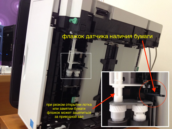
Столкнулся с такой проблемой — МФУ Kyocera M2530dn перестал печатать, вернее аппарат работает только с ручной подачи бумаги, а при попытке использовать основной лоток пишет «Кассета 1 не загружена» и «Загрузите бумагу в кассету 1». Бумага, естественно, в лотке присутствует.
Как выяснилось, проблема появилась после застревания бумаги во время печати и, по всей видимости, извлекали её из принтера какие-то душегубы. Интернет, а уж тем более документация к принтеру, внятного ответа по решению проблемы не дали, потому пришлось разбираться самостоятельно.
Всё оказалось довольно просто. При извлечении бумаги флажок датчика наличия бумаги в лотке зацепился за приводной вал, в результате чего не возвращался в своё рабочее положение. Вот и весь секрет.
Подписывайтесь на канал
Яндекс.Дзен
и узнавайте первыми о новых материалах, опубликованных на сайте.
Kyocera это профессиональная и достаточно дорогая печатная техника, но зато очень качественная, качестве печати у нее выше чем у аналогов так же как и срок службы. Но как и с любой другой возникают различные проблемы. Сегодня рассмотрим одну ситуацию на примере МФУ Kyocera ECOSYS M2135dn. По непонятным причинам МФУ перестает брать бумагу из основного лотка и выдает сообщение о том что бумаги нет, хотя она там конечно же есть. Сообщение выглядят следующим образом «Кассета 1 не загружена» и «Загрузите бумагу в кассету 1». Есть две причины (по крайне мере которые мне известны) которые могут к этому привести, первая это в настройка кто-то поменял устройство подачи по умолчанию и вторая это сломан флажок датчика наличия бумаги в лотке.
M2135dn не берет бумагу с основного лотка
Для начала нужно проверить настройки, сделать это намного проще и удобней через веб интерфейс. Открываем браузер вводим IP адрес принтера далее проходим авторизацию(стандартный логин пароль для этой модели Admin/3500) .
Сервисные пароли Kyocera — https://mita.by/articles/servisnyie-paroli-kyocera/
Далее открываем раздел «Настройки» и выбираем пункт «Бумага/Подача/Вывод». В открывшемся окне в пункте «Устр. подачи по умолч» должно стоять «Кассета 1» многоцелевой лоток это лоток ручной подачи.
Изменяем и сохраняем настройки.
Если вы не совсем в этом понимаете или кто-то до вас там что-то непонятное настроил можно вообще сделать сброс до заводских настроек.
Если это не помогло и принтер упорно сообщает о том что в лотке нет бумаги проверяем не сломан ли флажок датчика наличия бумаги. Для этого извлекаем полностью нижний лоток, переворачиваем МФУ на один из боком и смотрим вот на этот флажок.
Он может сломаться, либо застрять в приводном валу такое бывает когда вытаскивают застрявшею бумагу, так же с него может слететь пружинка. Если есть неисправности исправляем их, после этого МФУ должно начать работать с вероятностью 95%. Если настройки правильные, флажок на месте но МФУ все равно не печатает то причина в другом. Если у Вас есть другой способ исправить эту ошибку обязательно поделитесь им.
Содержание
- Kyocera — Вставьте бумагу в универсальный лоток. Решение
- Решение
- Инструкция по эксплуатации Kyocera Ecosys m2040dn
- Страница 290
- Настройка МФУ Kyocera для новичков
- Дубликаты не найдены
- Выжпрограммисты
- Сравнение струйных и лазерных печатающих устройств. Что выбрать для дома?
Kyocera — Вставьте бумагу в универсальный лоток. Решение
Иногда ошибка звучит по-другому, «добавьте бумагу в универсальный лоток», но смысл один. Симптом «проблемы» прост. На компьютерах под управлением Windows 10 при попытке отправить на печать любой документ на МФУ, Kyocera выдаёт ошибку. На табло надпись — «вставьте бумагу в универсальный лоток». При этом есть возможность указать другой лоток с бумагой, и тогда документ распечатается, но не бегать же к нему постоянно?
p, blockquote 1,0,0,0,0 —>
По какой-то причине матёрые приходящие админы в некоторых организациях никак не могут победить эту горе-проблемку. А дело тут просто в источнике бумаги. Дело в том, что универсальный лоток (верхний) у Kyocera потому и универсальный, что способен жрать любую бумагу. Будь то открытки, картон или любой нестандартный размер — все эти форматы Kyocera будет печатать с универсального лотка. А возникающая ошибка лишь говорит нам о том, что с компа на мфу отправлена задача напечатать документ нестандартного размера.
p, blockquote 2,0,1,0,0 —>
Иногда всё очень просто — например при печате из Word секретарша просто не замечает размер бумаги, что там указан не А4, а, скажем, Letter (письмо). Но чаще всего там стоит верный формат, но Kyocera всё равно пишет «Вставьте бумагу в универсальный лоток».
p, blockquote 3,0,0,0,0 —>
Решение
Нужно вычислить, в каком именно месте МФУ чётко указано расположение лотка для бумаги, а так же является ли проблема общей, либо такая печать идёт лишь с одного компа.
p, blockquote 4,0,0,0,0 —>
Если kyocera пишет ошибку «Вставьте бумагу в универсальный лоток» только с некоторых АРМ — дело в настройках на них. Первым делом у них следует проверить настройки печати. Для этого идём в панель управления — устройства и принтеры, правый тык на нужной мфу — настройка печати.
p, blockquote 5,1,0,0,0 —>
В первом же окне, на вкладке «основные» нужно убедиться в двух пунктах.
p, blockquote 6,0,0,0,0 —>
1. Тип материала для печати — должен быть Обычным, а не цветной бумагой и тд.
2. В качестве источника бумаги по-умолчанию не установлен универсальный лоток.
p, blockquote 7,0,0,0,0 —>
Обычно, на этом всё и заканчивается. Неизвестно почему, но во время штатной установки на некоторые компы драйвер Kyocera KX выставляет там левую бумагу.
p, blockquote 8,0,0,1,0 —>
Если же проблема наблюдается у любой машины, отправляющей на данную мфу задания по печати — нужно смотреть в конфигурацию самой Kyocera. Для этого идём в веб-часть мфу по её Ip адресу. Быстро узнать IP можно прям с Kyocera, выбрав Системное меню — печать отчёта — строка состояния. Логин и пароль по умолчанию разнятся у разных моделей, у 1135 это admin00, у 2035 — Admin.
p, blockquote 9,0,0,0,0 —>
Нас интересует пункт настройки устройства — бумага/подача/вывод. Проверьте что для первой касеты установлен тип материала обычный. Такой подвох вам скорее всего оставил бывший админ, либо какие-то шаловливые ручки. Верните настройки на свои места и бухгалтерии перестанут бегать к мфу, а вам скорее всего подарят пивасик.
p, blockquote 10,0,0,0,0 —>
Выдуманная проблема типа «вставьте бумагу в универсальный лоток» решена.
Источник
Инструкция по эксплуатации Kyocera Ecosys m2040dn
Страница 290
Настройка и регистрация (Системное меню) > Системное меню
Задайте действие возврата каретки при получении аппаратом кода возврата каретки (код
символа 0DH).
: Только возврат каретки, Перевод стр. и возв. кар., Игнорир. возврат
Укажите, нужно ли отображать имя задания, заданного в драйвере принтера.
В случае выбора [Вкл.] задайте имя задания, которое будет отображаться: [Имя
задания], [№+имя задания] или [Имя+№ задан.].
Укажите, нужно ли отображать имя пользователя, заданное в драйвере принтера.
Если в универсальный лоток загружена бумага, можно отдать ему приоритет при подаче
бумаги.
Выкл.: соблюдаются настройки драйвера принтера.
Автоподача: если в драйвере принтера выбрано «Авто» и в универсальном лотке
имеется бумага, то подача бумаги будет осуществляться из универсального лотка.
Всегда: если в универсальном лотке имеется бумага, то подача бумаги будет
осуществляться из универсального лотка независимо от настроек драйвера
принтера.
При печати с компьютера выберите способ подачи бумаги, если устройство подачи и тип
бумаги заданы.
Авто: Поиск устройства подачи бумаги, которое соответствует выбранному
формату и типу бумаги.
Фиксиров.: Печать на бумаге, загруженной в указанное устройство подачи бумаги.
Выберите действие, которое будет выполняться, когда во время печати во входном лотке
закончится бумага.
В случае выбора [Откл.] отображается сообщение «Загрузите бумагу в кассету #.» (где #
соответствует номеру кассеты) или «Загрузите бумагу в универсальный лоток.». При этом
печать прекратится.
Для возобновления печати загрузите бумагу в указанное на экране устройство подачи
бумаги.
Для печати с другого устройства подачи бумаги нажмите [Бумага]. Выберите нужное
устройство подачи бумаги и нажмите клавишу [OK].
В случае выбора [Вкл.] аппарат автоматически продолжит печать, если в другой кассете
содержится такая же бумага, что и в кассете, используемой в настоящий момент.
Установка разрешения при печати.
: 300 т/д, 600 т/д, Быстр1200 , Fine1200
Настройки, получаемые с драйвера принтера, имеют приоритет над настройками панели
управления.
Аппарат оснащен функцией сглаживания, которая обеспечивает высококачественную
печать с разрешением прибл. 9600 т/д (600 т/д × 15 градаций) × 600 т/д.
Источник
Настройка МФУ Kyocera для новичков

Дубликаты не найдены
Приветствую! Можете подсказать не получается сетевую папку настроить и сканирую через WSD сохраняет в папку Изображения на диске С. Ну как бы и фиг ты с ним но почему-то сохраняет 1 лист(JPEG) из пачки при этом сканирует все, и почему то не сохраняет в PDF хотя на сканере выбранн этот формат. Не сталкивались с подобным?
Проблема решена, заходишь в веб интерфейс принтера под админом меняешь установки в настройках скана, главное поставь разделение по страницам, в один файл по чему то гад не хочет делать, но хотя бы так)
Такая же проблема, пока не могу решить.
Автоп, возможно с опозданием пишем. Но такая проблема на Куосере возникла, типо кладешь стопку в автоподатчик, а сканирует лишь один лист. Как это можно исправить? Не сталкивались с таким?
Добрый день! А как настроить сканирование по usb? Просто нет сетки и хз как попасть в этот командный центр. Удивлен, что нет стандартного ПО для сканирования, как у других компаний.
Может посоветуете что-нибудь?
Спасибо сейчас попробую.
Спасибо, тоже нашла погуглив, помогло
Лично моё мнение про smb — это не удобно и не совсем безопасно. Я настраиваю по FTP. Коротко о плюсах FTP:
Тебе не нужно заводить на компах какие-то учетки, а если компы еще в домене, то будешь заходить на все принтера и менять пароли учеток постоянно. Лично у нас политиками безопасности удаляются все левые учетки. Кому интересно могу выложить пост с подробным описанием как я настраивал.
Просто несоответствие политик безопасности здравому смыслу. Служебные учётки с двадцатисимвольным фиксированным паролем нельзя, а левый FTP — можно. Настроили бы уже отправку по почте.
Я за, 3 день . с этим мфу.
Выкладывай, столкнулись с геморроем при сканировании на NAS.
чтобы не париться с учетками, просто открой безпарольный доступ в настройках сети на машине, куда сканируешь и все, никаких проблем.
@KurAi, привет! Решил реанимировать стоящие в кладовке две km1530. Нигде не могу найти инструкции как подключить плату печати и спарить её со своим комутером на win10 . Можете помочь кратким советом, ссылочкой?
Настраивал МФУ подсоединив к кому через роутер, я не знаю что именно влияло, может быть мой дешманский роутер нетгеар, может еще что то то инструкция нихрена не точная! Во первых ip и шлюз без нулей должны быть,
во -вторых. ну я не знаю как там в случае если сеть, я мфу m2035dn к персональному компу подрубал. НООО бляха муха!! 9,10,11 пункты до 7 пункта нужно делать! не заработало у меня нихрена пока случайно не мотнул инструкцию ниже..
Понимаю, что занимаюсь некропостингом, но есть отличный вариант сканирования с этих МФУ прямо на компьютер.
1. Устанавливаем TWAIN драйвер Kyocera
2. Затем в свеже установленной утилите TWAIN добавляем наш принтер. То есть выбираем модель, прописываем адрес.
3. Ставим программу NAPS2 (она бесплатна) и добавляем туда наш сканер, выбирая конечно же драйвер TWAIN.
АгА, и надо ходить постоянно от компа к сканеру по нескольку раз. автоподатчика то нету на 2030
Здрасте, @segorichev, подскажи, что делать если naps ругается, что устройство не подключено?
Предыдущие шаги выполнены, 2540 подключен по юсб.
либо сеть либо юсб, одно из двух. через сеть можно пользоваться веб настройками.
через сеть можно пользоваться веб настройками.
Дядя, ты туповат?
Спасибо тебе большое мил человек. Спас от мук настройки. До этого безуспешно пытался подружить встроенные инструменты Windows 10 с M2530dn.
Спасибо! именно этот способ помог. win10 kyocera m2035dn своя локалка.
добавлю некропостинга. а вы не знаете по какому порту/портам ходит твейн по сети. я хочу настроить с удаленного рдп сервера скан, но не понимаю какой порт октрыть
Узнал? Тоже надо
хых. да я че то тупил тогда. включил логгирование на микроте и просто посмотрел куда ломится драйвер. если я не путаюсь то порт 9090
с fs1018 сработает?
@KurAi а kyocera 1801 скан так же настраивается? а печать стандартно?
ps. знакомый столкнулся с проблемой подключения по сети. вот ищу предварительно что есть в нете. на данный момент нет доступа к kyocera 1801 и в глаза не видел. если что.
Спасибо тебе огромное, мил человек)
Сколько я в статей перерыла, видео пересмотрела, нифига не получалось.
а с твои постом за 3 минуты сделала:)
Вчера на работе ковырялся с Kyocera taskala 3253ci тот ещё кактус был, хоть в целом и всё норм и на винде работает, а мак его пока что не видит. Надеюсь сегодня добью.
как настроить аналогично в убунту?
Приветствую! Не подскажете как сканировать в один файл(PDF) если скан с планшета и сканируешь книгу скажем? Не сталкивались?
Для win10 есть софт Kyocera scan center
С дровами на сканер у киосеры плохо. Зато как standalone сканер — просто отлично работает! И по smb и по почте. Заодно, решается проблема стандартизации сканирования — кривые руки не зафигачат 600dpi 24bit в bmp
СПАСИБО)) Мне сейчас очень помогло =)
и ведь нашел через яндекс!
кто бы мог подумать нашел нужную тех. информацию на Пикабу ))
тоже в поиске нашёл, спасибо
я как раз загуглил) спасибо)
Так бля и получилось и это совсем не помогло 🙁
Если ты ещё тут скажи, что делать с такой проблемой? МФУ Киосера проработав секунд 30 уходит в сон и не реагирует, только если из розетки выдернуть — очухивается.


Выжпрограммисты
Я не думал, что у меня будет такой момент, когда я затупил и стало до ужаса стыдно — Либо это было не так фатально, либо не было свидетелей, чтобы потом напоминать об этом. Но всё изменилось, когда ̶н̶а̶р̶о̶д̶ ̶о̶г̶н̶я̶ ̶р̶а̶з̶в̶я̶з̶а̶л̶ ̶в̶о̶й̶н̶у̶ сегодня на работе при печати появилась полоса. Для особо любопытных могу сказать, что модель техники Kyocera 2040dn и что живучее этого МФУ я не видел отродясь.
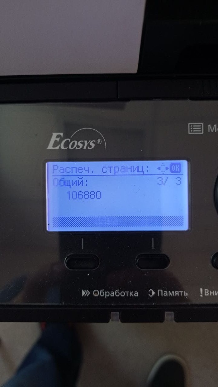
Почти 107 тыщ страниц (хоть это и с профилактическими работами, но без замены комплектующих) и первая полоса — результат впечатляющий.
По привычке мы (программист и системный администратор) достали картридж, все компоненты и протерли их от тонера. Постепенно мы добирались до самых недр этого монстра. После всех работ он был чище, чем когда вышел с завода.
Но самый фейл был в том, что изначально проверяли печать на полосу вордовскими документами, но т.к. процедуру очистки мы проводили не один раз, то решили просто делать ксерокопии не отходя от бедного япошки.
Полчаса рабочего времени было потрачено при горящей работе и необходимостью печати всех ненужных до этого момента документов, КАРЛ! Мне кажется, что если бы где-то в файлах на компе лежала библия, то и она бы понадобилась ежесекундно.
Самые умные из вас, наверное, догадались о том, что мы сканировали страницы С ПОЛОСОЙ и ожидали её там не увидеть после того, как уже столько времени совокуплялись с этой адской оргтехнической сатаной, однако до нас это дошло только тогда, когда мы решили проверить системный счётчик, распечатав его данные. Страница была без полосы. Теперь у нас заведена тетрадочка идиотских случаев.
Потому всем желаю не затупливать на работе и не тратить нервы как это сделали мы.

Сравнение струйных и лазерных печатающих устройств. Что выбрать для дома?
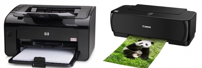

Линейных сравнений в лоб по технологии печати навалом, а вот про качественные показатели этих продуктов почти не нашел. По этому, сжато и на доступном языке поделюсь крупицами опыта и знаний, которые Вам не расскажут в тырнетах.
Для начала Струйка
Как мы все знаем, в струйной технологии, изображение на лист переносится по средством вытравливания чернил на лист через дюзы печатной головки. Но мало кто смотрит на то, каким образом головка травит чернила.
Epson и Brother используют пьезоэлектрические головки разработанные самим Epson (Упрощённая схема технологии ниже)
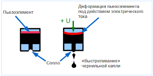
Canon, HP, Lexmark использует пузырьково-струйные головки (Упрощённая схема технологии)
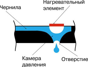
Ну а теперь к сути. Пьезоэлектрика имеет меньшую погрешность в размере капли и возможность выдавать капли с большей частотой в единицу времени. Пузырьково-струйная технология имеет большую погрешность в размере капли по сравнению с Пьезоэлектрикой, однако простота конструкции кратно увеличивает надежность печатающей головки. А вот теперь, самое важное отличие, которое нужно помнить, так что, сейчас читаем внимательно. Пьезоэлектрические печатающие головки являются деталью устройства. Пузырьково-струйные головки являются расходным материалом. Кто еще не понял разницу, объясняю. «Заполосила» головка, и штатная чистка не помогла, пьезу придется тащить в сервис и заказывать деталь, Пузырьково-струйную получится поменять самостоятельно. Однако, для самого дешевого домашнего сегмента правило не работает, так как устройство продается дешевле чем стоит печатающая голова (в надежде на то, что они потом оригинальной краской с Вас доберуть «своё»). Политика производителей такая. Тут ничего не поделать.
А теперь чуть статистики: 90% поломок струйных устройств приходится на блок печатающей головки. Если стандартная процедура чистки дюз в драйвере устройства не помогла, то Ваши шансы на реанимацию устройства начинают стремиться к 0. Какие у Вас варианты? Колхозить самому (в моей практике было такое. Человеку удалось прочистить засохший дюз с помощью бытового чистящего средства от засоров. Но это из разряда чудес) Либо тащить в сервис. Некоторые сервисники имеют так называемые «Ультразвуковые ванны» для чистки. Но процесс чистки может затянуться на 3-4 суток, все это сопровождается постоянными проверками на аппарате (т.е постоянным присутствием инженера рядом) и шансем нууууу
50% на успех. Если Ваше устройство стоило
4 000р Вам придётся умолять их починить Ваше устройство. При цене диагностики
500р, как вы думаете сколько инженер может у Вас попросить денег за ремонт? Скорее всего, Вас просто сразу отправят в магазин за новым устройством. Такие дела.
Давайте перейдем к возможным комплектациям струйных устройств, по параметру подачи чернил в блок печатной головки:
1) Комплектация картриджей со встроенной головкой.
2) Комплектация устройства с картриджами.
3) Комплектация устройства с СНПЧ (Система непрерывной подачи чернил)
В 3 случае, печать листа получается дешевле, в 1 самая дорогая. Стоимость устройств как раз наоборот, 3 самая дорогое, а 1 самое дешевое. Головки рассчитаны на определенный пролив чернил через себя (Естественно с погрешностью), по этому в случае 1, вы гарантированно придете и купите еще чернил, и производитель получит свои денежки. В случае 3, вы будете просто заливать краску в специальные отсеки (оригинал или нет решать Вам) пока не сдохнет головка. Самая любопытная комплектация это 2. Она поддается модингу в комплектацию 3 (как правило это колхоз) Что-то вроде того, что на фото ниже
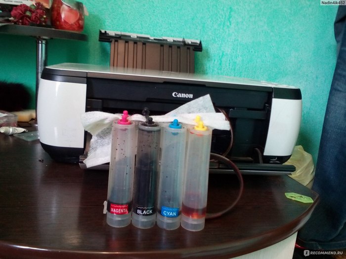
Так как устройства с картриджами не имеют места для расположения блока СНПЧ, и иногда его подключение происходит напрямую в печатающую головку, и как следствие постоянно приоткрыта крышка устройства и еще куча неудобств, это решение далеко не для всех. Производители не рекомендуют колхозить СНПЧ, по этому четких инструкций вы никогда не найдете, а в сервисах скорее всего откажут в установке, так как есть вероятность «убить» печатающую головку. К такому решению приходят копи-центры, центры печати фотографий на документы и т.д. чтобы получить дешевое устройство и дешевый «клик», модинг производят своими силами на свой страх и риск. Для дома, я бы порекомендовал смотреть в сторону совместимых картриджей, проверенных брендов, если у Вас уже есть устройство которое работает на картриджах с чернилами.
И вот, только после этой стены текста, я могу перейти к ответу на вопрос в Коментарии.
Плюсы струйной технологии пред лазером:
— Дешевой отпечаток (В СНПЧ)
— Ничего страшного не произойдет если, вы задубите скрепку на листе (Правда и ничего хорошего тоже)
Минусы струной технологии пред лазером:
— Почти не ремонтопригоден. В домашнем лазернике (из моей первой статьи) замена картриджа, подразумевает замену
80% механики аппарата.
— Нужно периодически (хотябы 1-2 раза в неделю) «проливать головку» печатая на нем, или просто делать чистку дюз, чтобы не засохла.
— Устройство постоянно должно быть включено в розетку.
— Низкая скорость печати
— Чернила водорастворимые (бывает пигментные чернила конечно, но совместимых аналогов на дешевые устройства не встречал)
Минусы лазерной технологии перед струйной
— Устройства дороже чем струйные
— цветной клик БЕЗУМНО дорой
— Забудешь скрепку в листе — прикончишь аппарат
— Устройство больше в габаритах на столе
Вывод: Однозначно ответить на вопрос не представляется возможным. Перед приобретением нужно задуматься над задачами, и под них выбирать устройство. Вводных данных по выбору в 2х статьях с избытком хватит для сознательного решения.
P.S. почему не стал сравнивать цены? Политика реселлеров в регионах слишком разная. И то, что в локальных магазинах г. Москвы (любого другого мегаполиса) стоит одних денег, может быть значительно дороже в региональных городках. Все ситуации индивидуальны.
Надеюсь материал получился не нудным и кому нибудь будет полезен. Всем добра. Если нужно, могу пройтись по офисному сегменту.
Источник