- Page 1
Operating Manual SC300 Version B 05/2019 97100010042… - Page 2
Colour coding The colour coding of the components used in our documents is exclusively for documentation purposes. Contact your thyssenkrupp Aufzugswerke sales partner for details of colours for your specific products. Form of address In the interest of better legibility, we use exclusively the masculine grammatical form, for example «fireman». -
Page 3: Table Of Contents
Service life ………………………. 26 Dimensions ………………………… 27 4.4.1 Machine …………………………. 27 Transportation and storage …………………… 28 Packaging ………………………… 28 Transport ………………………… 29 5.2.1 Fork-lift truck transport……………………. 29 5.2.2 Crane transport………………………. 29 Checking the delivery …………………….. 32 Intermediate storage…………………….. 32 thyssenkrupp Aufzugswerke Operating Manual, SC300 | 97100010042 | 05/2019…
- Page 4
7.11 Replacing the encoder…………………….. 80 7.11.1 Replacing the second encoder …………………. 81 7.12 Replacing the traction sheave …………………… 82 7.13 Rope clamp …………………………. 87 7.14 Blocking clamp ………………………. 89 Commissioning ………………………. 91 Work steps………………………… 91 Maintenance ………………………… 92 thyssenkrupp Aufzugswerke Operating Manual, SC300 | 97100010042 | 05/2019… - Page 5
12.2.10 Wachendorff WDG100H-38-1024 encoder — installation instructions ………. 116 12.2.11 Wachendorff WDG100H-38-1024 encoder — data sheet………….. 117 12.2.12 SC300 brake — EU type test certificate EU-BD 700/1 ……………. 118 12.2.13 Bremse SC300 — EU-Konformitätserklärung [2019_04_25]…………… 123 12.2.14 Bernstein data sheet switch OR81GL……………….. 124 12.2.15 Bernstein Declaration of Conformity contactor OR81GL ………….. -
Page 6: About These Instructions
Chap. 1, P. 6 List • Top item of a list – Sub-item of a list – Sub-item of a list • Top item of a list • Top item of a list thyssenkrupp Aufzugswerke Operating Manual, SC300 | 97100010042 | 05/2019…
-
Page 7: Safety
Read and comply with the warning. 2.1.3 Indication of possible damage to property NOTICE Hazard with possible damage to property! May lead to product function impairments or function loss. Read and comply with the warning. thyssenkrupp Aufzugswerke Operating Manual, SC300 | 97100010042 | 05/2019…
-
Page 8: Safety Requirements
Clearly establish all areas of responsibility prior to any activity. Always wear the personal protective equipment made available to you. Prior to work, make people aware of the dangers of electrical current. thyssenkrupp Aufzugswerke Operating Manual, SC300 | 97100010042 | 05/2019…
-
Page 9: Dangers In Handling The Drive
• The drive may only be operated in a closed machine room or secured shaft. • The drive may only be operated with the cover and rope guard fitted to the traction sheave. thyssenkrupp Aufzugswerke Operating Manual, SC300 | 97100010042 | 05/2019…
-
Page 10: Warranty And Liability
2.3.1 Structural modification of the product The product is configured in the factory and delivered ready for operation. If changes are made to the product, the entire warranty of thyssenkrupp Aufzug- swerke GmbH shall become null and void. 2.3.2 Use in line with intended use The product has been constructed using state-of-the-art technology and in line with the recognised technical safety regulations.
-
Page 11: Personal Protective Equipment
Safety Personal protective equipment with the intended use. thyssenkrupp Aufzugswerke GmbH shall not be liable for any damage arising from such use or for any damage arising due to operator errors. In order to comply with the intended use of the product: •…
-
Page 12: Description
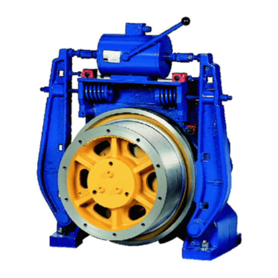
Product The SC300 is a frequency-controlled (V3F) synchronous machine excited by permanent magnets and belongs to the product group of the thyssenkrupp com- pact gearless. The abbreviation SC stands for «synchronous» and «compact gearless». The ab- breviation M means «middle», S means «short».
-
Page 13: Brake
3.2.1 Brake The brakes of the SC300 are intended as a stop brake for static application and perform the additional function of a braking device for protection of the upward- moving elevator car against overspeed and against unintentional movement of the elevator car Chap. 12.2, P. 101.
-
Page 14: Machine Base Frame
Description Product The redundantly structured braking device of the SC300 consists of two separ- ately arranged shoe brakes with guided compression springs that directly affect the brake drum. The brake is opened electromagnetically during operation to ensure failure safety. The design as a double-vane magnet with two separate brake magnet coils means it is possible to open both brake shoes separately (electrical).
- Page 15
Safety switch A rope cover safety switch is attached at the machine base frame. As soon as this is removed (for example to mount the hoist), the installation is shut down. thyssenkrupp Aufzugswerke Operating Manual, SC300 | 97100010042 | 05/2019… -
Page 16: Electrical Connection
Cable glands are fitted for strain relief on the supply lines for the motor, double- vane magnet and position switches. 3.2.4 Cooling The SC300 has no fan. The machine is cooled by means of free convection. Accessories For maintenance work and emergency rescue measures, the following access- ory parts are available: •…
-
Page 17: Manual Brake Release For One Brake Circuit
Fig. 10 ATR_2_12_0140_0 example as an aid to hanging up the ropes. The rope clamp is only available for standardised traction sheaves with a spe- cified number of grooves and groove clearance. thyssenkrupp Aufzugswerke Operating Manual, SC300 | 97100010042 | 05/2019…
-
Page 18: Blocking Clamp
410/440 mm and a rope pulley with diameter 400 mm. 3.4.1 Traction sheave protection device A modified rope cover with rope guards is fitted to the traction sheave as a pro- tection device. Fig. 13 ATR_2_12_0001_0 thyssenkrupp Aufzugswerke Operating Manual, SC300 | 97100010042 | 05/2019…
-
Page 19: Machine Base Frame Protection Devices
There are different versions of rope guards for single and double wrap. All rope guards can be used for the ASL range of 650 — 1250 mm and adjusted in different ways. Fig. 15 ATR_2_12_0003_0 thyssenkrupp Aufzugswerke Operating Manual, SC300 | 97100010042 | 05/2019…
- Page 20
The safety devices are positioned at the feet of the machine base frame. Fig. 16 ATR_2_00_0001_0 Shift protection with shortened wall clearance For wall clearances < 250 mm, there are special shift protection elements for low wall clearances. Fig. 17 ATR_2_00_0006_0 thyssenkrupp Aufzugswerke Operating Manual, SC300 | 97100010042 | 05/2019… -
Page 21: Technology
14 Nominal frequency Starting current/approach mo- 15 Max. permitted current ment Version for operation with fre- 17 Insulating material class quency inverter 19 Manufacturer Weights Version Complete machine [kg] Traction sheave/brake drum [kg] thyssenkrupp Aufzugswerke Operating Manual, SC300 | 97100010042 | 05/2019…
-
Page 22: Brake
4.1.2 Brake If the braking device of the SC300 is to be used as a protection device against overspeed for the upward moving elevator car and unintended car movement, the speed governor or a device with a similar high level of safety must trigger the brake electrically.
-
Page 23: Electrical Data
Additional data: Chap. 12.2, P. 101 Double-vane magnet Manufacturer Kendrion Designation LED 1650007 Pull-in voltage [VDC] Holding voltage [VDC] Pick-up current 1.67 Holding current 0.84 Pull-in power 300.6 /150.3 Holding power 75.2 /37.6 thyssenkrupp Aufzugswerke Operating Manual, SC300 | 97100010042 | 05/2019…
-
Page 24: Encoder
Tab. 6 ATR_1_12_0029_1 Brake monitoring Every opening and closing operation of the brake must be monitored by the el- evator control system. The following position switches are deployed for brake monitoring of the SC300: Other information: Chap. 6.6.2, P. 49 Chap. 12.2, P. 101 4.2.2 Encoder An encoder is deployed to control the machine;…
-
Page 25: Machine Base Frame
Max. permitted voltage (earth cable, 1200 measured at the terminal blocks) Voltage at the motor terminals (wire- 1200 wire) Rise time of measured voltage (10- [ns] > 100 90%) at the motor terminal thyssenkrupp Aufzugswerke Operating Manual, SC300 | 97100010042 | 05/2019…
-
Page 26: Ambient Conditions
• Ambient temperature between +5 °C and +40 °C • Site altitude without derating up to 1000 m amsl 4.3.2 Service life The machine is configured for a service life of: • 30 000 hours of operation thyssenkrupp Aufzugswerke Operating Manual, SC300 | 97100010042 | 05/2019…
-
Page 27: Dimensions
Technology Dimensions Dimensions 4.4.1 Machine Fig. 21 ATR_2_12_0116_0 thyssenkrupp Aufzugswerke Operating Manual, SC300 | 97100010042 | 05/2019…
-
Page 28: Transportation And Storage
Transportation and storage Packaging Transportation and storage Packaging The SC300 is packaged in VCI foil to protect the machine against environ- mental influences during transport. Further packaging depends on the order and is country-specific (air/sea/land freight). Refer to the delivery note for the dimensions and weight.
-
Page 29: Transport
Only use tested and adequately dimensioned lifting gear. The specified means of transport are only configured for transportation of the machine, the installed brake and traction sheave. Do not use them to transport any other loads. thyssenkrupp Aufzugswerke Operating Manual, SC300 | 97100010042 | 05/2019…
- Page 30
1. Attach chains or ropes directly to all four corner holes on the machine base frame. 2. After transporting, remove any wood used for protection during transport. Transport without machine base frame 90° Fig. 24 ATR_2_12_0186_0 thyssenkrupp Aufzugswerke Operating Manual, SC300 | 97100010042 | 05/2019… - Page 31
In the case of inclined pulling, the eyes of the eyebolts must be parallel to the hoisting equipment. 2. Attach chains or ropes to both eyebolts. 3. Remove eyebolts after transport. thyssenkrupp Aufzugswerke Operating Manual, SC300 | 97100010042 | 05/2019… -
Page 32: Checking The Delivery
Protect it against the formation of condensation, moisture and dirt. • The assembly must not be stored outdoors. Bare parts have no application of long-lasting preservative. • Comply with notes regarding standstill maintenance Chap. 9.1, P. 92 thyssenkrupp Aufzugswerke Operating Manual, SC300 | 97100010042 | 05/2019…
-
Page 33: Installation
Separate mention is made of operations that require a different number of quali- fied personnel. The machine base frame of the SC300 is delivered pre-assembled (including rope pulley). Depending on the order, feet and/or insulation elements are also supplied. The arrangement and number of insulation elements are defined ac- cording to the order.
-
Page 34: Position Of The Insulation Elements
Rope offset for rope diameter 10 mm Item G3 Item G4 Item G5 Item G6 Static total load on all insulation elements Number of insulation elements up to 53 kN up to 40 kN Tab. 9 ATR_1_12_0078_0 thyssenkrupp Aufzugswerke Operating Manual, SC300 | 97100010042 | 05/2019…
- Page 35
Item G6 Static total load on all insulation elements Number of insulation elements up to 105 kN up to 95 kN up to 85 kN up to 75 kN up to 65 kN Tab. 10 ATR_1_12_0080_0 thyssenkrupp Aufzugswerke Operating Manual, SC300 | 97100010042 | 05/2019… - Page 36
Item G6 Static total load on all insulation elements Number of insulation elements up to 105 kN up to 95 kN up to 85 kN up to 75 kN up to 65 kN Tab. 11 ATR_1_12_0082_0 thyssenkrupp Aufzugswerke Operating Manual, SC300 | 97100010042 | 05/2019… - Page 37
Single wrap without rope anchorage Fig. 29 ATR_2_12_0069_0 Item G3 Item G4 Item G5 Item G6 Static total load on all Number of insulation elements insulation elements up to 53 kN up to 40 kN Tab. 12 ATR_1_12_0085_0 thyssenkrupp Aufzugswerke Operating Manual, SC300 | 97100010042 | 05/2019… -
Page 38: Aligning The Machine Base Frame And Machine
Components subjected to one-sided loads can deform and break; this can lead to failure of the drive. The drive must be horizontal. Use a spirit level to check and add support if necessary. thyssenkrupp Aufzugswerke Operating Manual, SC300 | 97100010042 | 05/2019…
- Page 39
The traction sheave and rope pulley bearings must be exactly parallel. 5. Align the rope departure of traction sheave and rope pulley in line with the general arrangement drawing plumb to the elevator car and/or counter- weight. thyssenkrupp Aufzugswerke Operating Manual, SC300 | 97100010042 | 05/2019… -
Page 40: Rope Arrangement
(Ra) in relation to one another. With standard grooves, R = rope groove diameter + 4 mm. Check the groove clearance on the basis of the general arrangement drawing. thyssenkrupp Aufzugswerke Operating Manual, SC300 | 97100010042 | 05/2019…
- Page 41
Hang up the return of the rope pulley to the traction sheave on the 2nd groove of the traction sheave and from there to the 2nd groove of the rope pulley. thyssenkrupp Aufzugswerke Operating Manual, SC300 | 97100010042 | 05/2019… -
Page 42: Standard Version Of Protection Devices
On installations without a rope pulley, a two-piece rope cover is used. Fig. 36 ATR_2_12_0132_4 Item Designation Item Designation Mounting holes 1. Mount the fastening panel(s) with bolts in the mounting holes on the ma- chine base frame. thyssenkrupp Aufzugswerke Operating Manual, SC300 | 97100010042 | 05/2019…
-
Page 43: Rope Guard On The Rope Pulley
2. Tighten the securing bolts with the prescribed tightening torque. Chap. 12.1, P. 101 Fig. 37 ATR_2_12_0215_0 Item Designation Item Designation Rope pulley Rope guard 6.3.3 Traction sheave rope cover safety switch Fig. 38 ATR_2_12_0214_1 thyssenkrupp Aufzugswerke Operating Manual, SC300 | 97100010042 | 05/2019…
-
Page 44: Protection Devices For Earthquake Regions
Make sure that there is a maximum of 90° between the rope guards. 3. After alignment, tighten the securing bolts of the rope guards with the pre- scribed tightening torque. thyssenkrupp Aufzugswerke Operating Manual, SC300 | 97100010042 | 05/2019…
-
Page 45: Rope Pulley On The Machine Base Frame
• Insulation elements without underlay for machine room without floor pave- ment • Insulation elements with underlay for machine room with floor pavement (≤ 60 mm height); support made from Multiplex laminated wood 140x140x80 thyssenkrupp Aufzugswerke Operating Manual, SC300 | 97100010042 | 05/2019…
- Page 46
2. Drill holes for the anchoring devices at the marked positions. If there is steel reinforcement in the concrete, use alternative holes. 3. Secure the shift protection elements with 2 anchoring devices. Use 1 anchoring device per tab. thyssenkrupp Aufzugswerke Operating Manual, SC300 | 97100010042 | 05/2019… -
Page 47: Wiring Diagrams
Item Designation Motor Encoder Optional 2nd encoder Safety switch Winding Thermistor 6.5.2 Brake -B07.1 -B07 -X07 -Y07 Fig. 43 ATR_2_12_0110_0 Item Designation Item Designation Double-vane magnet Position switch 1 Position switch 2 thyssenkrupp Aufzugswerke Operating Manual, SC300 | 97100010042 | 05/2019…
-
Page 48: Electrical Connection
In the standard version, cable glands complying with EMC requirements are pre-installed at the terminal box for the motor supply lead and temperature mon- itoring. When connecting these lines, apply the shielding. Chap. 12.2, P. 101 thyssenkrupp Aufzugswerke Operating Manual, SC300 | 97100010042 | 05/2019…
-
Page 49: Brake
0.6 — 0.8 x 3.5 Tab. 15 ATR_1_12_0106_1 Terminal strip Fig. 45 ATR_2_12_0113_1 6.6.2 Brake There is a position switch for each of the two brake shoes; these have to be connected individually. Chap. 6.5.2, P. 47 thyssenkrupp Aufzugswerke Operating Manual, SC300 | 97100010042 | 05/2019…
-
Page 50: Machine Base Frame
Connection terminals Cable feed through Connection type 2 screw connections (M3.5) Terminal area [mm²] 0.5 — 1.5 (AWG 20-16) Cable feed through M20 x 1.5 with self-sealing grommet Tab. 18 ATR_1_10_0006_1 Fig. 48 ATR_2_12_0052_0 thyssenkrupp Aufzugswerke Operating Manual, SC300 | 97100010042 | 05/2019…
-
Page 51: Encoder
Item Designation Torque support Securing bolt Connection cable Use the D-Sub plug connector to connect the pre-assembled connection cable to the inverter in accordance with manufacturer’s documentation Chap. 12.2, P. 101. Fig. 49 ATR_2_12_0195_0 thyssenkrupp Aufzugswerke Operating Manual, SC300 | 97100010042 | 05/2019…
- Page 52
Chap. 12.2, P. 101. Colour Function A inverted green yellow black B inverted grey violet N inverted white Negative Strand Screen brown Positive Tab. 19 ATR_1_12_0097_1 Additional information: Chap. 12.2, P. 101 thyssenkrupp Aufzugswerke Operating Manual, SC300 | 97100010042 | 05/2019… -
Page 53: Concluding Measures
Installation Concluding measures Concluding measures After completion of all installation work on the drive, cover the drive to pro- tect it against dust and dirt until commissioning. thyssenkrupp Aufzugswerke Operating Manual, SC300 | 97100010042 | 05/2019…
-
Page 54: Work On The Product
3. Check the following areas for traces of grease and oil: Bearing cover Each screw on the bearing cover Brake drum Brake linings Carry out a visual check of the lower and/or inner area of the traction sheave. thyssenkrupp Aufzugswerke Operating Manual, SC300 | 97100010042 | 05/2019…
- Page 55
If necessary, check on a daily basis whether oil/ grease is still leaking. If this is the case: shut down the installation. Tab. 20 ATR_00_0004_0 thyssenkrupp Aufzugswerke Operating Manual, SC300 | 97100010042 | 05/2019… -
Page 56: Lubrication
Fill a total of 50 g of lubricating grease in at least three partial quantities of (2 x 15, 1 x 20 g). 1. Fill the first partial quantity (15 g) of the lubricating grease (approx. 12 presses of the specified grease gun). thyssenkrupp Aufzugswerke Operating Manual, SC300 | 97100010042 | 05/2019…
-
Page 57: Opening The Brakes Manually
If no more grease is leaking after one hour, the installation can be put back into operation. No other steps for the regular lubrication of the SC300 are necessary. The second roller bearing of the motor shaft on the encoder side and the roller bear- ings of the rope pulley have lifetime lubrication.
-
Page 58: Opening Brake Circuit Manually
• Auxiliary tool, part number 6246 000 9240 1. Insert the auxiliary tool between the brake shoe and housing. 2. Open one brake circuit manually with the auxiliary tool in the direction shown. thyssenkrupp Aufzugswerke Operating Manual, SC300 | 97100010042 | 05/2019…
-
Page 59: Manually Opening Both Brake Circuits Simultaneously
2. Block the doors and landing calls. 3. Operate the brake release lever. The brake shoes open. 4. Pay attention to noises or other anomalies and, if applicable, determine the cause and rectify it. thyssenkrupp Aufzugswerke Operating Manual, SC300 | 97100010042 | 05/2019…
-
Page 60: Checking Remaining Lining Thickness/Wear Limit
Separate mention is made of operations that require a different number of quali- fied personnel. 7.6.1 Concentricity measurement A concentricity measurement must be carried out in the following cases: • After replacement of a brake drum thyssenkrupp Aufzugswerke Operating Manual, SC300 | 97100010042 | 05/2019…
-
Page 61: Checking Brake Shoe Stroke
If the noise on opening and closing the brake becomes significantly louder, this can be an indication of brake lining wear. In this case, the brake linings and brake shoe stroke must be checked immediately. thyssenkrupp Aufzugswerke Operating Manual, SC300 | 97100010042 | 05/2019…
- Page 62
1. Attach the dial gauge to the housing. The measuring needle must be posi- tioned in the middle of the brake shoe ( moulded arrow). 2. Start a run with electrically opened brakes. thyssenkrupp Aufzugswerke Operating Manual, SC300 | 97100010042 | 05/2019… - Page 63
0,35 mm Fig. 60 ATR_2_12_0166_1 Required tools • Feeler gauge 0.35 mm, 0.4 mm and 0.45 mm Work steps ü Brake lining thickness is adequate. Chap. 7.5, P. 60 ü Brake drum is cold. thyssenkrupp Aufzugswerke Operating Manual, SC300 | 97100010042 | 05/2019… -
Page 64: Adjusting The Brake Shoe Stroke
Chap. 7.6.3, P. 64 7.6.3 Adjusting the brake shoe stroke The brake shoe stroke only needs to be adjusted if the previous check indic- ated that the specified values were not complied with. thyssenkrupp Aufzugswerke Operating Manual, SC300 | 97100010042 | 05/2019…
- Page 65
5. Switch the installation off at the main switch and secure against being switched on inadvertently. 6. Correct the value by turning the adjusting screw for the brake shoe stroke. Setting value for brake shoe stroke depending on measurement method used Chap. 7.6.2, P. 61 thyssenkrupp Aufzugswerke Operating Manual, SC300 | 97100010042 | 05/2019… -
Page 66: Brake Test Switch
1. Open and close the first brake circuit manually with the auxiliary tool. The indicator lamp on the brake test switch must go of and/or on. 2. Repeat the test on the second brake circuit. thyssenkrupp Aufzugswerke Operating Manual, SC300 | 97100010042 | 05/2019…
- Page 67
(off — on — off). 5. Secure the setting with the lock nut. 6. Remove the feeler gauge. The indicator lamp must come on. 7. Make the setting at the second brake test switch. thyssenkrupp Aufzugswerke Operating Manual, SC300 | 97100010042 | 05/2019… -
Page 68: Double-Vane Magnet
If the setting nut of the compression spring of the double-vane magnet is not sealed and locked, the idle stroke must be checked and, if required, adjusted and sealed by the manufacturer. In this case, contact your sales partner. thyssenkrupp Aufzugswerke Operating Manual, SC300 | 97100010042 | 05/2019…
-
Page 69: Checking The Double-Vane Magnet
The idle stroke must always be at least 2 mm. ü The brake has dropped out. 1. Switch the installation off at the main switch and secure against being switched on inadvertently. thyssenkrupp Aufzugswerke Operating Manual, SC300 | 97100010042 | 05/2019…
-
Page 70: Checking The Braking Deceleration
Two skilled persons are required for the operations described in this chapter. Before starting work , one person must be designated as supervisor. Separate mention is made of operations that require a different number of quali- fied personnel. thyssenkrupp Aufzugswerke Operating Manual, SC300 | 97100010042 | 05/2019…
-
Page 71: Measures Before Start Of Check
2. Visual inspection of whether brake linings are soiled with oil or grease. If this is the case, shut down the installation immediately and replace both brake shoes. Chap. 7.1, P. 54 3. Check remaining lining thickness/wear limit. Chap. 7.5, P. 60 thyssenkrupp Aufzugswerke Operating Manual, SC300 | 97100010042 | 05/2019…
-
Page 72: Static Single-Circuit Brake Test With 115% Rated Load In The Lower And Upper Shaft Area
This test must be carried out during initial commissioning and if the installation dimensions change. National regulations might require a different procedure. thyssenkrupp Aufzugswerke Operating Manual, SC300 | 97100010042 | 05/2019…
-
Page 73: Single-Circuit Brake Test On Elevator Car With 100% Rated Load In Downward Direction In The Lower Shaft Area
5. Insert the auxiliary tool between the brake shoe and housing without exert- ing force. 6. Initiate a run with electrically opened brakes and at rated speed in down- wards direction. thyssenkrupp Aufzugswerke Operating Manual, SC300 | 97100010042 | 05/2019…
-
Page 74: Single-Circuit Brake Test Of Elevator Car With 0% Rated Load (Elevator Car Empty) In Upward Direction In The Middle Of The Shaft
1.00 1.20 1.60 1.75 2.00 2.50 3.00 3.50 Minimum deceleration up to 41% load com- 0.72 0.75 0.80 0.85 0.87 pensation [m/s²] Minimum deceleration 41 — 45% load compens- 0.57 0.60 0.65 0.70 0.72 ation thyssenkrupp Aufzugswerke Operating Manual, SC300 | 97100010042 | 05/2019…
-
Page 75: Slipping Ropes
Only put the installation into operation when the following basic requirements have been met: thyssenkrupp Aufzugswerke Operating Manual, SC300 | 97100010042 | 05/2019…
-
Page 76: Replacing The Brake
The brake shoes must be replaced at least in the following situations: • Remaining lining thickness inadequate. • Brake linings soiled with oil or grease. The brake shoes must always be replaced in pairs. thyssenkrupp Aufzugswerke Operating Manual, SC300 | 97100010042 | 05/2019…
- Page 77
• Emery paper Required tools • Brake lining scraper • 2 fork spanners WAF 30 mm • 2 fork spanners WAF 24 mm • 2 fork spanners WAF 18 mm • Circlips pliers thyssenkrupp Aufzugswerke Operating Manual, SC300 | 97100010042 | 05/2019… - Page 78
Chap. 7.6.3, P. 64 10. Set the brake test switch. Chap. 7.7, P. 66 Check the settings Even if only one brake shoe is replaced, the following tests must be carried out for both brake shoes. thyssenkrupp Aufzugswerke Operating Manual, SC300 | 97100010042 | 05/2019… -
Page 79: Setting The Initial Spring Tension
Compression spring tensioned Spring plate Housing contact surface Initial spring tension distance Spring length with initial tension Spring length slack Recessed part in the housing (approx. 124 mm) (approx. 12 mm) thyssenkrupp Aufzugswerke Operating Manual, SC300 | 97100010042 | 05/2019…
-
Page 80: Replacing The Encoder
Operating manual for frequency inverter Switch the installation off at the main switch and secure against being switched on inadvertently. Installation and removal of the encoder Chap. 12.2, P. 101 thyssenkrupp Aufzugswerke Operating Manual, SC300 | 97100010042 | 05/2019…
-
Page 81: Replacing The Second Encoder
4. Secure the first encoder in line with the manufacturer specifications. 5. Connecting the second encoder. 6. Readjust the first encoder in accordance with Frequency inverter oper- ating manual. thyssenkrupp Aufzugswerke Operating Manual, SC300 | 97100010042 | 05/2019…
-
Page 82: Replacing The Traction Sheave
Outer circle of holes (forcing Fastening screw tension disc threads) Compression spring for brake Required special tool/material • Rope clamp • Round slings • Tensioning straps/lifting gear • Chain hoist • Shackles thyssenkrupp Aufzugswerke Operating Manual, SC300 | 97100010042 | 05/2019…
- Page 83
9. Secure ropes on the other side of the traction sheave with round sling and chain hoist. 10. Take off and secure the ropes. 11. Secure traction sheave with lifting gear. thyssenkrupp Aufzugswerke Operating Manual, SC300 | 97100010042 | 05/2019… - Page 84
13. Relieve tension of both compression springs by unscrewing the adjusting screw until the traction sheave is free. 14. Undoing the securing bolts of the tension disc thyssenkrupp Aufzugswerke Operating Manual, SC300 | 97100010042 | 05/2019… - Page 85
17. Tighten the three bolts alternately and evenly. The traction sheave separates from the shaft. 18. Undo the tensioning strap used to secure in axis direction. 19. Use lifting gear to take off the traction sheave. thyssenkrupp Aufzugswerke Operating Manual, SC300 | 97100010042 | 05/2019… - Page 86
3. Align the locations of the feather key and groove in relation to one another. 4. Push the traction sheave onto the motor shaft, making sure not to damage the brake shoes. thyssenkrupp Aufzugswerke Operating Manual, SC300 | 97100010042 | 05/2019… -
Page 87: Rope Clamp
• To hold the elevator car in position • As an auxiliary device to hanging up the ropes • As an auxiliary device for rescue operation (pulling out of the safety gear) Chap. 10.5, P. 98 thyssenkrupp Aufzugswerke Operating Manual, SC300 | 97100010042 | 05/2019…
- Page 88
4. Place the rope clamp on the frame profile at the bottom. 5. Insert the screws and screw the halves together. The ropes are clamped. 6. Tighten the screws firmly. Ropes are fixed. Fig. 71 ATR_2_12_0226_0 thyssenkrupp Aufzugswerke Operating Manual, SC300 | 97100010042 | 05/2019… -
Page 89: Blocking Clamp
• If the rope traction is insufficient during maintenance work and emergency operation (slipping ropes). • As an auxiliary device for rescue operation (pulling out of the safety gear) Chap. 10.5, P. 98 Fig. 72 ATR_2_12_0144_1 Item Designation Item Designation Pressure screws Securing bolt thyssenkrupp Aufzugswerke Operating Manual, SC300 | 97100010042 | 05/2019…
- Page 90
3. Tighten the pressure screws firmly. Ropes are fixed. NOTICE! Damage to the elevator installation if the drive is operated with the blocking clamp! Remove the blocking clamp after completion of the work. thyssenkrupp Aufzugswerke Operating Manual, SC300 | 97100010042 | 05/2019… -
Page 91: Commissioning
17. In the terminal box of the double-vane magnet, attach the supplied sign with direction arrow (Up/Down) in a clearly visible position above the trac- tion sheave on double-vane magnet corresponding to the direction of travel. thyssenkrupp Aufzugswerke Operating Manual, SC300 | 97100010042 | 05/2019…
-
Page 92: Maintenance
Standstill maintenance Maintenance Standstill maintenance If the SC300 is not installed or used for a longer period, the measures described below must be carried out every year: Two skilled persons are required for the operations described in this chapter. Before starting work , one person must be designated as supervisor.
- Page 93
15. Check that electrical connections and lines are in good condition, i.e. un- damaged; check that they are securely attached and safe. 16. Check the function and setting of the safety switches (if present) by remov- ing the protection devices (rope cover). thyssenkrupp Aufzugswerke Operating Manual, SC300 | 97100010042 | 05/2019… - Page 94
This operating manual only describes the emergency rescue measures for the SC300 machine. Other important information can be found in the operating manual «Rescue operation» of the elevator installation. - Page 95
(techni- cian 2). 4. Move the elevator car into the next landing by carefully opening the brakes and moving the handwinding wheel. 5. Remove the handwinding wheel. thyssenkrupp Aufzugswerke Operating Manual, SC300 | 97100010042 | 05/2019… - Page 96
Fig. 75 ATR_2_12_0227_0 Item Designation Item Designation Mounting bolts Centring pin Pressure arm with centring pin Fig. 76 ATR_2_12_0228_0 Item Designation Item Designation Bracket Drain valve Lever Pressure cylinder with groove thyssenkrupp Aufzugswerke Operating Manual, SC300 | 97100010042 | 05/2019… - Page 97
The centring pin points downwards. Fig. 78 ATR_2_12_0027_0 Item Designation Item Designation Pressure arm Hydraulic hoisting mechanism 3. Close the drain plug on the hydraulic hoisting mechanism by turning the lever to the right. thyssenkrupp Aufzugswerke Operating Manual, SC300 | 97100010042 | 05/2019… - Page 98
If the path of the hydraulic hoisting mechanism is not sufficient to get the elev- ator car (or counterweight) free, the following steps must be carried out. thyssenkrupp Aufzugswerke Operating Manual, SC300 | 97100010042 | 05/2019… - Page 99
May lead to function impairments or function loss of the elevator installation. Rectify the cause of the malfunction. Establish and ensure the non-disruptive and proper and adequate state of the elevator installation. thyssenkrupp Aufzugswerke Operating Manual, SC300 | 97100010042 | 05/2019… - Page 100
Product disposal Disposal 11.1 Product disposal Dispose of the various components of the product in an environmentally re- sponsible manner in accordance with applicable national and local laws, rules and regulations. thyssenkrupp Aufzugswerke Operating Manual, SC300 | 97100010042 | 05/2019… - Page 101
12.2 Manufacturer information Also see about this Baumer BISS-C encoder — operating and installation instructions P. 103 Baumer encoder — declaration of conformity P. 104 Kübler Sendix 5873 encoder — installation instructions P. 105 thyssenkrupp Aufzugswerke Operating Manual, SC300 | 97100010042 | 05/2019… - Page 102
Heidenhain ECN 413 encoder — declaration of conformity P. 115 Wachendorff WDG100H-38-1024 encoder — installation instructions P. 116 Wachendorff WDG100H-38-1024 encoder — data sheet P. 117 SC300 brake — EU type test certificate EU-BD 700/1 P. 118 Bremse SC300 — EU-Konformitätserklärung [2019_04_25] P. 123 Bernstein data sheet switch OR81GL P. 124 Bernstein Declaration of Conformity contactor OR81GL P. 126… - Page 103
Safety instructions Mounting instructions Electrical commissioning Observe the applicable law, directives and standards for use respectively in- Avoid any shocks or mechanical impact on housing or shaft. Do not modify the encoder electrically nor perform any wiring work while the tended use. - Page 104
EU-Konformitätserklärung EU Declaration of Conformity Déclaration UE de Conformité Wir erklären in alleiniger Verantwortung, dass die Produkte, auf die sich diese Erklärung bezieht, die grund- legenden Anforderungen der angegebenen Richtlinie(n) erfüllen und basierend auf den aufgeführten Norm(en) bewertet wurden. We declare under our sole responsibility that the products to which the present declaration relates comply with the essential requirements of the given directive(s) and have been evaluated on the basis of the listed standard(s). - Page 105
600 039 001 Deutsch English Installationsanleitung Installing instructions for Drehgeber rotary encoders Wichtig! Important! Vor Inbetriebnahme des Gebers unbedingt lesen. It is imperarive to read these instructions before setting the encoder in operation. Mit diesem Geber haben Sie ein Präzisionsmessgerät erworben. Beachten Sie stets die Angaben und Hinweise des Datenblattes, This encoder is a precision measuring instrument. - Page 106
Deutsch English Montagehinweis für Geber mit Welle: Installation instructions for encoders with shaft: Wellen auf Versatz überprüfen. Check shafts for offset. Axialversatz /Axial offset Radialversatz / Radial offset Winkelfehler /Angle error Entnehmen Sie die Werte X1, X2 und X3 dem Datenblatt der Kupplung. Refer to the coupling data sheet for the values X1, X2, and X3. - Page 107
Montageanweisung – Drehgeber Typ 5873 mit Konuswelle Assembly instructions – encoder type 5873 with tapered shaft 1. Befestigungsschraube in die Motorwelle 2. Befestigungsschraube mit 3 Nm anziehen. +0,5 schrauben. Dabei wird der Drehgeber in den Tighten the fixing bolt with 3 +0.5 Konus gezogen. - Page 108
Demontageanweisung – Drehgeber Typ 5873 mit Konuswelle Disassembly instructions – encoder type 5873 with tapered shaft 1. 2x Schrauben lösen. 2. 2x Schrauben mit Unterlegscheiben entfernen. Loosen 2 x bolts. Remove 2 x bolts with washers. 3. Befestigungsschraube lösen. 4. Durch das Lösen der Befestigungsschraube Loosen fixing bolt. - Page 109
2) Short circuit to 0V or to output, one channel at a time, supply voltage correctly applied Terminal assignment: Signals: SUB-D connector (male) 15pin Signal 2 3 4 5 6 7 8 22.11.11 Unit of measurement Fritz Kübler GmbH ThyssenKrupp Zähl- und Sensortechnik millimeter 22.6.11 78054 VS-Schwenningen Kübler Type: Customer Type: 9.5.11 Tolerances DG1706… - Page 111
DIN EN 100 015 – 1 CECC 00015 – 1 RS-485 CLOCK CLOCK = 3.6 … 14 V at encoder, integrato, Mounting Instructions CLOCK frequency [kHz] see, vedi, Istruzioni di montaggio RS-485 0.8 … 1.2 V DATA Included in delivery Patch coating (… - Page 112
Montage . Assembly . Montage . Montaggio . Montaje ECN 413 Maße in mm Dimensions in mm Cotes en mm Dimensioni in mm Dimensiones en mm M d = 5 ± 0.5 Nm For multiple use, max. 3x. À Riutilizzo max 3x. Uso múltiple máx. - Page 113
ECN 413 • Absoluter Singleturn-Drehgeber/Absolute singleturn encoder • Version Thyssen • Konuswelle/Taper shaft 19.5±1 50.5±1 16.85±0.1 6.45±0.2 Á À Â ¬ 6 Ã A = Lagerung Kundenwelle k = Kundenseitige Anschlussmaße Ä m = Messpunkt Arbeitstemperatur À = Selbstsichernde Schraube M5 x 50 DIN 6912 SW4, Anzugsmoment 5+0.5 Nm Á… - Page 114
ECN 413 Absolute Positionswerte EnDat 2.2 Absolute position values Bestellbezeichnung/Ordering designation EnDat 01 Positionen/U / Positions per revolution 8 192 (13 bit)/8192 (13 bits) Code/Code Dual/Pure binary –1 –1 Elektr. zul. Drehzahl/ bei Genauigkeit † 1 500 min /± 1 LSB; † 12 000 min /±… - Page 116
Wachendorff Automation GmbH & Co. KG Industriestraße 7 • D-65366 Geisenheim WDG100H-xx-yyyy-ABN-I24-K3-C07 Tel.: +49(0)672 2 /99 65 -25 Fax: +49(0)672 2 /99 65-70 xx = Ø 28, 38, 40, 42mm eMail: wdg@wachendorff.de yyyy = PPR 1024, 4096 www.wachendorff-automation.de Steckergehäuse/Schirm Kabel, mit Gebergehäuse leitend cable, verbunden… - Page 117
Wachendorff Automation GmbH & Co. KG Industriestrasse 7 D-65366 Geisenheim Tel.: +49 (0) 67 22 / 99 65 — 25 Fax: +49 (0) 67 22 / 99 65 — 70 www.wachendorff-automation.de Hohlwellen — Drehgeber WDG 100H Spezifikationen Mechanische Daten Gehäuse — Flansch: Aluminium — Rückseite:… - Page 124
Technical Data Contactless switch in BI2 Series OR81 Description OR81GL-DHTN-0005-ALX Article number 6659381003 Wiring diagramm not connected Operating diagram Operating force F ≤ 12 N Fixed positioning with e.g. fixing screw M5 according to the standard DIN EN ISO 4762. Identifying characteristics in accordance with EN 60947-5-2 Electrical data Switching element function NPN — N.O… - Page 125
Technical Data Electromagnetic compatibility (EMC) Electromagnetic field test IEC 61000-4-3 Electrostatic discharge test IEC 61000-4-2 Electrical fast transient immunity test (Burst) IEC 61000-4-4 Impulse voltage withstand ability (Surge) IEC 61000-4-5 Radiated disturbance field strength EN 55011 Mechanical Data Enclosure PA6, red Cover PA66, black Plunger actuator… - Page 127
Technische Daten Isolierstoffgekapselter Grenztaster Baureihe I88 Typbezeichnung I88-A1Z KS Artikelnummer 6116869135 Schaltsymbol Betätiger ausgefahren Fixierte Positionierung z.B. mit Befestigungsschraube M5 Betätiger nach DIN EN ISO 4762 eingefahren Schaltdiagramm Betätiger ausgefahren Betätiger eingefahren Elektrische Daten Bemessungsisolationspannung 250 V AC Konv. thermischer Strom 10 A Bemessungsbetriebsspannung 240 V… - Page 128
Technische Daten Mechanische Daten Gehäuse PA6 Taromid B280G7X0 Weichkomp.:TPE Multiflex G40 A21 BTZ 2811 N 0081 Deckel Hartkompo.: PA6.6 Ultramid A3X2G5 Betätigung Separater Betätiger (Stahl) Umgebungstemperatur -30 °C … +80 °C Kontaktart 1 Schließer (X) mit Zwangsöffnung Mechanische Lebensdauer 1 x 10 Schaltspiele Schalthäufigkeit ≤… - Page 130
Assembly Instructions Double Spreading Solenoid Type: LED165000A08 Device no.: LED1650007 Translation of German Assembly Instructions Kendrion (Donaueschingen/Engelswies) GmbH August-Fischbach-Straße 1 78166 Donaueschingen +49 771 8009 0 info@kendrion.com Phone: E-mail:… - Page 131
Double Elevator Solenoid EU Declaration of Conformity LED165000A08… - Page 132
Double Spreading Solenoid LED165000A08 Contents Identification General information Purpose of this document Warranty provisions Service Limitation of liability Notes for users Location information in the assembly instructions Presentation of warnings Basic safety instructions Warning of general hazards 4.1.1 General workplace hazards Intended use Spare and wear parts Residual risks… -
Page 133: Identification
Double Spreading Solenoid LED165000A08 Identification Identification Identification data Manufacturer: Kendrion (Donaueschingen/Engelswies) GmbH Product: Double Spreading Solenoid Type: LED165000A08 Device number: LED1650007 Manufacturer Kendrion (Donaueschingen/Engelswies) GmbH Street: August-Fischbach-Straße 1 Location: 78166 Donaueschingen Phone: +49 771 8009 0 E-Mail: info@kendrion.com About these operating instructions Version/revision: Date created: 02.01.2018…
-
Page 134: General Information
Double Spreading Solenoid LED165000A08 General information 2.1 Purpose of this document These instructions are approved exclusively for specially trained personnel. These instructions enable the safe and efficient handling of the double spreading solenoid, for which the general term electromagnet is used in the following.
-
Page 135: Limitation Of Liability
Double Spreading Solenoid LED165000A08 2.4 Limitation of liability All information and instructions in this manual have been compiled with due regard to applicable standards and provisions, the best available technology and our many years of knowledge and experience. The manufacturer accepts no liability for damages in the following cases: …
-
Page 136: Notes For Users
Double Spreading Solenoid LED165000A08 Notes for users 3.1 Location information in the assembly instructions All direction and location information in this manual refers to the technician’s workplace. The installation position is horizontal, as shown in Figure 1. Top of the electromagnet Left Right Bottom…
- Page 137
Double Spreading Solenoid LED165000A08 Warning levels Signal word Used for… Possible consequences if the safety instructions are not followed: DANGER Personal injury Death or severe (imminent danger) injury WARNING Personal injury Death or severe (potentially dangerous injury situation) CAUTION Personal injury Slight or minor injury NOTE Procedures… - Page 138
Double Spreading Solenoid LED165000A08 Warning signs Special safety instructions are included at the relevant points. They are identified by the following symbols. General danger point This sign is shown for activities where there is a risk of personal injury and extensive damage to property. -
Page 139: Basic Safety Instructions
Double Spreading Solenoid LED165000A08 Basic safety instructions This section provides an overview of all important safety aspects for the optimum protection of personnel as well as for safe and trouble-free operation. Assembly, device settings, maintenance and disassembly and electrical connections should only be carried out by qualified personnel. …
-
Page 140: Warning Of General Hazards
Double Spreading Solenoid LED165000A08 4.1 Warning of general hazards This section identifies residual risks that may be caused by the electromagnet, as determined by a risk assessment. To reduce health hazards and avoid dangerous situations, always follow the safety instructions listed here and the safety instructions in the other sections of this manual.
- Page 141
Double Spreading Solenoid LED165000A08 Stored charges DANGER Risk of death from stored charges Electronic components can store electric charges that are retained even after switching off and disconnecting the power supply. Contact with these components can result in serious injury or death. … - Page 142
Double Spreading Solenoid LED165000A08 Hand injury WARNING Risk of injury to the hands When working on the electromagnet, always be aware that injuries to the hands from sharp edges, pinching or crushing are possible. Hard-to-reach places on or in the electromagnet can cause bruising of the fingers and hands, and angular components, points and corners on or in the electromagnet can cause stab wounds and cuts. - Page 143
Double Spreading Solenoid LED165000A08 Hot surfaces WARNING Risk of injury from hot surfaces Surfaces of components can become very hot during operation. Skin contact with hot surfaces can cause severe skin burns. For all work in the vicinity of hot surfaces, always wear heat-resistant protective work clothing and gloves. -
Page 144: Intended Use
Double Spreading Solenoid LED165000A08 4.2 Intended use The electromagnets (double elevator solenoids) in the Kendrion Elevator Line are linear solenoids with a short stroke and high magnetic force. They are used as actuating magnets in elevator or escalator drives for the release of brakes. The double elevator solenoid consists of two magnet systems in a single housing, which press in two opposite directions.
-
Page 145: Spare And Wear Parts
Double Spreading Solenoid LED165000A08 4.3 Spare and wear parts WARNING Risk of injury from the use of incorrect spare parts The use of incorrect or faulty spare parts can create hazards for personnel and cause damage, malfunctions or total failure. …
-
Page 146: Responsibility Of The Operator
Double Spreading Solenoid LED165000A08 4.5 Responsibility of the operator Operator The operator is the person who operates the electromagnet for industrial or commercial purposes or makes it available to a third party for use/application and who bears the legal product responsibility during operation for the protection of users, personnel or third parties.
-
Page 147: Training
Double Spreading Solenoid LED165000A08 4.6 Training Personnel must be trained by the operator on a regular basis. 4.7 Requirements of personnel WARNING Risk of injury due to insufficient personnel qualifications Unqualified personnel working on the electromagnet or present in the hazard area of the electromagnet give rise to hazards that can cause serious injuries and significant damage to property.
-
Page 148: Personal Protective Equipment
Double Spreading Solenoid LED165000A08 Technical specialists must be capable of assessing and carrying out the work assigned to them, identifying and eliminating potential hazards, and be familiar with the relevant standards and provisions. Technical specialists must comply with the provisions of the applicable statutory regulations for the prevention of accidents.
-
Page 149: Description Of The Electromagnet
Double Spreading Solenoid LED165000A08 Description of the electromagnet This section provides a comprehensive overview of the structure and function of the electromagnet. If possible, have the electromagnet with you while reading it. This is the best way to familiarise yourself with it. 5.1 Applications The double elevator solenoids with a short stroke and high magnetic force are intended for use as actuating magnets in elevator or escalator drives for the…
-
Page 150: Marking On The Electromagnet
Double Spreading Solenoid LED165000A08 5.2 Marking on the electromagnet The following marks can be found on the electromagnet: CE marking Indicates conformity with applicable EU directives That apply to the product That require a CE marking (see Declaration of Conformity on page 2) Nameplate for the specific identification of the electromagnet Additional information plate with…
-
Page 151: Structure Of The Electromagnet
Double Spreading Solenoid LED165000A08 5.3 Structure of the electromagnet Figure 3 to Figure 7 provide an overview of the most important components for the installation of the electromagnet: The installation position is horizontal, as shown here. Figure 3: Horizontal installation position Mounting option using four threaded holes on base, which is located on the…
- Page 152
Double Spreading Solenoid LED165000A08 The mechanical connection can be made on a threaded rod on the left and right, which transmits the stroke. See type drawing for details Figure 5: Mechanical connection Electrical connection using cable fitting and connection housing Figure 6: Electrical connection Lever for emergency manual actuation… -
Page 153: Technical Data
Double Spreading Solenoid LED165000A08 5.4 Technical data Mechanical data Dimensions in mm Approx. 390 x 165 x 215 (L x W x H) See type drawing for details Space required in mm Approx. 390 x 165 x 215 (L x W x H) See type drawing for details Weight 38 kg…
-
Page 154: Installation
Double Spreading Solenoid LED165000A08 Installation CAUTION Sharp edges The thread on the armature axis may have sharp edges. Beware of cuts to the fingers, hands and arms. Put on protective gloves before working on and around the area of the armature axis. WARNING Electric shock! If connection cables, plug connections or lines are damaged or…
-
Page 155: Installing The Electromagnet
Double Spreading Solenoid LED165000A08 6.2 Installing the electromagnet CAUTION Sharp edges The thread on the armature axis may have sharp edges. Beware of cuts to the fingers, hands and arms. Put on protective gloves before working on and around the area of the armature axis.
- Page 156
Double Spreading Solenoid LED165000A08 4 threaded holes for mounting in the machine or system. See type drawing for details Figure 9: Mounting option Note the required tightening torque for the screws you use to fix the electromagnet. For the mechanical connection, there are two armature axes with an M20 thread on the left and right. -
Page 157: Removing The Manual Release Lever
Double Spreading Solenoid LED165000A08 Screw locking varnish in addition to adhesive for securing threaded connections Figure 11: Screw locking varnish The stroke of the electromagnet is factory-set and secured by two nuts on the left and right of the armature axis with an adhesive for securing threaded connections.
-
Page 158: Supply And Installation
Double Spreading Solenoid LED165000A08 Figure 13: Electromagnet without manual release lever 6.3 Supply and installation CAUTION Electric shock! Contact with live parts poses an immediate risk of death by electrocution. Damage to the insulation or individual components can be life-threatening. …
-
Page 159: Electrical Connection
Double Spreading Solenoid LED165000A08 6.3.2 Electrical connection The connection must be in accordance with the standards and directives applicable at the installation location. For voltage and current consumption, see section 5.4 Technical data or the type drawing. The supply connections for electric current are located on the top of the electromagnet in the connection housing.
- Page 160
Double Spreading Solenoid LED165000A08 Figure 16 provides an overview of the individual components in the electromagnet’s connection housing. Connecting bridge Earthing connection Insert connection cable through PG11 Terminal Varistor S14K275 Figure 16: Overview of connection housing Figure 17 shows the connection positions for the electrical connection. Connect earthing cable Make the electrical connection using the… - Page 161
Double Spreading Solenoid LED165000A08 Figure 18: Wiring diagram Make the electrical connection as shown on the wiring diagram on the type drawing, noting the tightening torques specified on the type drawing. After completing the electrical connection, screw the cover back onto the connection housing with the two slotted screws and sealing rings. -
Page 162: Startup
Double Spreading Solenoid LED165000A08 Startup WARNING Risk of burns The electromagnet becomes very hot during and for some time after operation. There is a risk of skin burns in the event of direct contact with the electromagnet. If you need to touch the electromagnet, wear suitable fire- resistant protective gloves.
-
Page 163: Emergency Manual Actuation
Double Spreading Solenoid LED165000A08 Emergency manual actuation CAUTION Crush hazard When the manual release lever is actuated, there is a risk of crushing the fingers and hands between the manual release lever and the housing due to the spring return of the armature. …
-
Page 164: Maintenance And Care
Double Spreading Solenoid LED165000A08 Maintenance and care NOTE Never open the electromagnet! This may only be done by the manufacturer. For the purpose of maintenance and inspection of the brake system, a coil can be bridged to test the brake shoes individually. The following procedure must be followed: …
-
Page 165: Shutdown
Double Spreading Solenoid LED165000A08 10 Shutdown WARNING! Residual energies from compression springs When switching off the voltage, keep at a safe distance from the movable parts of the electromagnet. 10.1 Disassembly, final shutdown 1. Switch off the machine or system in which the electromagnet is installed. 2.
-
Page 166: Index
Double Elevator Solenoid LED165000A08 11 Index Obligations About Applications Protective equipment Personal Description Destruction Recycling Requirements of personnel Emergency manual actuation Residual risks General hazards Safety instructions Basic Service Identification Shutdown Installation Spare and wear parts Electrical connection Startup Mounting Structure Limitation of liability Technical data…
- Page 167
PERFECT EMV-Kabelverschraubung || PERFECT EMC-cable gland PERFECT EMV-Kabelverschraubung || PERFECT EMC-cable gland Grundlagen, Montageablauf Unsere PERFECT EMV-Kabelverschraubung Typ 50.6xx M/EMV ermöglicht eine lückenlose und durchgängige Kontaktierung. Die Hutmutter und der Lamelleneinsatz werden einfach auf die Leitung geschoben. Der freigelegte Leitungsschirm wird um den Lamel- leneinsatz gefalzt und darauf steckt man den Zwischenstutzen. - Page 168
Normally open (make contact) Rated load Right-hand version Groove gap dimension (centre-to-centre distance between ropes) RS-RC Rope suspension with rear counterweight RS-SC Rope suspension with side counterweight Synchron Compact Pulley diameter Single wrap thyssenkrupp Aufzugswerke Operating Manual, SC300 | 97100010042 | 05/2019… - Page 169
List of abbreviations Program for the calculation of elevator specifications (thyssenkrupp Lift Designer) Unintended elevator car movement Volatile Corrosion Inhibitor thyssenkrupp Aufzugswerke Operating Manual, SC300 | 97100010042 | 05/2019… - Page 170
Aufzugswerke Operating Manual, SC300 | 97100010042 | 05/2019… - Page 171
Aufzugswerke Operating Manual, SC300 | 97100010042 | 05/2019… - Page 172
Elevator Technology thyssenkrupp Aufzugswerke GmbH Bernhäuser Straße 45 73765 Neuhausen a.d.F., Germany P: +49 7158 12-0 doku.elevator.plant.de@thyssenkrupp.com eli.thyssenkrupp-elevator.com 05/2019…
- Печать
Страницы: [1] 2 3 … 27 Вниз

Тема: ThyssenKrupp — вопросы по ТИССЕНУ (архив) (Прочитано 108617 раз)
0 Пользователей и 1 Гость просматривают эту тему.
electroni
Отредактировал сообщение, т.к. здесь был непонятный ответ на что-то, удаленное еще до меня.
А удалять первое сообщение темы — ну никак.
Зеленым буду выделять вопросы, на которые далее следуют ответы. Это облегчит поиск способов решений проблем с лифтами
МВС
« Последнее редактирование: Январь 26, 2014, 08:10:06 от MBC »

Записан
спасибо
Александр Карелин
montazhnik
32 эт, 2 м/с. 1000кг .
Привод безредукторный. Если кабина тяжелее противовеса на 200кг. — то не едет вверх, а если противовес тяжелее — то не едет вниз.
Такое ощущение что мощности маловато. Наладкой занимается не наша фирма(мы, в основном, по OTISам)
« Последнее редактирование: Май 02, 2013, 21:33:40 от MBC »
Записан
montazhnik
Ну вот я и добрался до лифтфорума.
Как то я писал о проблеме с мощностью двигателя. Проблема оказалась в импульсном датчике. Он оказался хитроватым: он при повороте на 360″ должен выдавать два импульса, а этот — ТОЛЬКО ОДИН. Привезут новый датчик — и дело наладится 
Записан
1.И так, надеюсь что кто-нибудь всёже объяснит дауну  что за процедура AFOC…
2. Вопрос второй — 2 лифта при подходе или старте с этажа «теряет место» — загорается на табло JU и ползёт до следующего этажа , ошибок в памяти нет, безопасность не пропадает…
3. Один их лифтов неточно остонавливается, причём только на крайнем верхнем и через раз…
Записан
Какая гадость эти ваши Тиссены — все проблемы в несбалансированых противовесах и фиговых грузувзвесках…
Записан
Наладчик
Так у вас получилось пустить их в работу? И еще у вас есть на tac 50 принципиальные эл. схемы а то документация на лифты еще не пришла а придется запускать в кратчайшие сроки, хоть посмотреть что за лифт такой.
Записан

В электронике нет чудес есть хреновые контакты
Повторю то, что говорил лет пять назад (про ОТИС): «Сначала узнай технику, а потом обхаивай»
С ОТИСом ты свое мнение (со временем) поменял на прямо противоположное. Надеюсь, что аналогичное произойдет и с ТИССЕНом.
Да уж когда 2 наладчика напару потратили 4 часа на то чтобы понять чтоже происходит с лифтом… 
О качестве оборудования- тут недавно GEN сдали, так там накидали лишнии 110 -откат получился 6 мм, но лифты работали… Могу на вскидку сказать 2 параметра изменив которые мог за 5 секунд это устранить, даже не залазия в шахту… И если бы не упёртый дед (наладчик из Отис, который требовал строгого соответствия с таблицей параметров я бы так и сделал) А тут 34 — 68 кг лишние и лифт постоянно сбивается и идёт на юстировку…
А уж регулировка LMSS с помощью ключа на 36
« Последнее редактирование: Октябрь 09, 2008, 12:42:09 от Наладчик »
Записан
Наладчик
Так у вас получилось пустить их в работу? И
Они уже были запущены…
еще у вас есть на tac 50 принципиальные эл. схемы а то документация на лифты еще не пришла а придется запускать в кратчайшие сроки, хоть посмотреть что за лифт такой.
http://naladchik2006.narod.ru/ARHIV/ThyssenKrupp.htm
тут схемы есть…
Записан
110 кг накидали лишнии.
Да я не спорю что техника в целом не плохая, но как-то не впечатляет… И лазить под потолок (к частотнику) зависая там на закладных, наблюдая за поведением пустой кабины тоже не фонтан…
« Последнее редактирование: Октябрь 09, 2008, 12:36:46 от Наладчик »
Записан
И лазить под потолок (к частотнику) зависая там на закладных, наблюдая за поведением пустой кабины тоже не фонтан…
К слову Altivar 71 можо настраивать используя адаптер Modbus — Bluetooth дальность 10 метров. Лифтек же вроде дистребьютер Тиссена, почему не обзавестись аналогичными сервисной утилитой и аппаратными средствами для комфортной работы?
Записан

Ещё я удивлялся что лишнии 34-68 кг на противовесе приводит к постоянным сбоям лифта….
Записан
Вчера я запустил этот тиссан. Заново переиницилизировал. Прописал ему что он тиссан и марку мотора. Лифт в МП поехал. С ревизии едет только вверх. Сегодня опять буду ковырять. Я очень упёртый человек. И я доковыряюсь до истины (весь лифт расковыряю)!!!
Вопрос: из МП идёт вормально, а с ревизии только вверх. Кнопки ревиз исправны.
Записан
там с датчиками периодически какие-то заморочки в ревизии — сам пока не разбирался, но при мне монтажники по ним проводили магнитом, который там специально лежали и лифт ехал…
Записан
Все седня сдали заказчику Корейский Thyssen
Для себя сделал следующие выводы, лифт сам по себе не плохой если бы не несколько но.
Первое но: Отсутствует сервистул или какой другой экранчик через который можно посмотреть режим работы станции и ошибки, может он в природе существует но штатно не комплектуется в станцию, а каждый раз с собой нотник тащить ой как не удобно, особо если объект за 300 км находится.
Второе но: Попадаются узлы явно не продуманные до конца (читай сырые) которые приходится тщательно обрабатывать напильником. В нашем случае пришлось переделывать тяги ловителей и потолок кабины.
Третье но: Халатно отнеслись к поставке лифта, не допоставили часть оборудования а часть оборудования было от другой модели лифта, в итоге нам пришлось извинятся перед заказчиком а потом заканчивать объект за три дня, пахали до 2х часов ночи.
Четвертое: Станция приходит с завода не совсем настроенная хотя это нормально, документация на русском языке есть и вобщем достаточно подробная, но с некоторыми неточностями и недомолвками. В частности в схеме которая пришла с паспортом этого лифта датчики загрузки должны подключатся к +24V а на деле оказывается к -24V как то странно почему я это должен экспериментальным путем выяснять а не через схиму. Так же не смог в документации найти описание некоторых перемычек на платы и подключение некоторых плат, в частности расключение дверного контроллера DCU 2 которым был укомплектован наш лифт. Хотя может у меня старая документация была.
А в остальном лифт как лифт не чего особенного.
Записан
В электронике нет чудес есть хреновые контакты
Что тебе пришлось делать с тягой? По потолку опорную раму я тебе послал. Зачем переделывать было?
Записан
- Печать
Страницы: [1] 2 3 … 27 Вверх
| Автор | Сообщение | ||
|---|---|---|---|
|
Заголовок сообщения: Re: ThysenKrupp Synergy немецкий
|
|||
|
Доброго времени суток Лифт работал порядка 5лет+ |
||
| Вернуться к началу |
|
||
|
pani_pa |
Заголовок сообщения: Re: ThysenKrupp Synergy немецкий
|
|
|
Фотозавесу для начала поменяйте… |
| Вернуться к началу |
|
|
AlexDoki |
Заголовок сообщения: Re: ThysenKrupp Synergy немецкий
|
||
|
Спасибо за ответ, но напряжение мерили на плате MF внутри кабины. |
||
| Вернуться к началу |
|
||
|
Kostian376 |
Заголовок сообщения: Re: ThysenKrupp Synergy немецкий
|
||
|
|||
| Вернуться к началу |
|
||
|
Akhmet |
Заголовок сообщения: Re: ThysenKrupp Synergy немецкий
|
||
|
Здравствуйте! |
||
| Вернуться к началу |
|
||
|
baks1519 |
Заголовок сообщения: Re: ThysenKrupp Synergy немецкий
|
|
Реальное имя: Бахтияр
|
|
| Вернуться к началу |
|
|
Akhmet |
Заголовок сообщения: Re: ThysenKrupp Synergy немецкий
|
||
|
В меню 0500 62 и 64 указывают что платы установлены, при подключении к TMI платы откликаются. |
||
| Вернуться к началу |
|
||
|
Akhmet |
Заголовок сообщения: Re: ThysenKrupp Synergy немецкий
|
||
|
Зашёл в меню af0c, экран что то показал-не запомнил. Но на табло начало показывать вместо черточки if и начала работать инспекция. Поставил в норму: спустился на этаж ниже в точную,вызвал к себе-приехал, но двери не открыл. Пока искал причину лифт похоже запутался в этажах, показывает на табло первый этаж хотя стоит на крайнем верхнем этаже и в норме пытается ехать вверх. Догнал до нижнего этажа. Включил автообучение шахты, доехал до середины шахты встал. Переключил в ревизию, и вверх и вниз только дёргается. Ошибки 5800, 9400. В норме 5800, 0d36,5700, 0a4f. Может кто подскажет что можно сделать? |
||
| Вернуться к началу |
|
||
|
лифтанутый |
Заголовок сообщения: Re: ThysenKrupp Synergy немецкий
|
||
|
Не надо перескакивать и дергать все подряд. «Зашёл в меню af0c, экран что то показал-не запомнил» — забавно. «Автообучение» и «коррекция» — это есть два разных процесса. |
||
| Вернуться к началу |
|
||
|
Akhmet |
Заголовок сообщения: Re: ThysenKrupp Synergy немецкий
|
||
|
И снова здравствуй thyssen! |
||
| Вернуться к началу |
|
||
|
baks1519 |
Заголовок сообщения: Re: ThysenKrupp Synergy немецкий
|
|
Реальное имя: Бахтияр
|
|
| Вернуться к началу |
|
|
Akhmet |
Заголовок сообщения: Re: ThysenKrupp Synergy немецкий
|
||
|
Платы МР 4 и 8 отключены. Лифт без них катался 2 года. Остальные платы откликаются. |
||
| Вернуться к началу |
|
||
|
Akhmet |
Заголовок сообщения: Re: ThysenKrupp Synergy немецкий
|
||
|
Всем привет! Ребята подскажите: за что отвечают платы 4МР и 8МР? И зачем их отключают при наладке? |
||
| Вернуться к началу |
|
||
|
baks1519 |
Заголовок сообщения: Re: ThysenKrupp Synergy немецкий
|
|
Реальное имя: Бахтияр
|
Платы MP — это платы входов/выходов. |
| Вернуться к началу |
|
|
Akhmet |
Заголовок сообщения: Re: ThysenKrupp Synergy немецкий
|
||
|
Разъёмы выдернуть. В меню 0500 в параметре 62 и 64 показывает что установлены. 63 и 64 пусто. |
||
| Вернуться к началу |
|
||
- Manuals
- Brands
- ThyssenKrupp Manuals
- Elevators
- SC300
- Operating manual
-
Contents
-
Table of Contents
-
Bookmarks
Quick Links
Operating Manual
SC300
Version B
05/2019
97100010042
Related Manuals for ThyssenKrupp SC300
Summary of Contents for ThyssenKrupp SC300
-
Page 1
Operating Manual SC300 Version B 05/2019 97100010042… -
Page 2
Colour coding The colour coding of the components used in our documents is exclusively for documentation purposes. Contact your thyssenkrupp Aufzugswerke sales partner for details of colours for your specific products. Form of address In the interest of better legibility, we use exclusively the masculine grammatical form, for example «fireman». -
Page 3: Table Of Contents
Service life ………………………. 26 Dimensions ………………………… 27 4.4.1 Machine …………………………. 27 Transportation and storage …………………… 28 Packaging ………………………… 28 Transport ………………………… 29 5.2.1 Fork-lift truck transport……………………. 29 5.2.2 Crane transport………………………. 29 Checking the delivery …………………….. 32 Intermediate storage…………………….. 32 thyssenkrupp Aufzugswerke Operating Manual, SC300 | 97100010042 | 05/2019…
-
Page 4
7.11 Replacing the encoder…………………….. 80 7.11.1 Replacing the second encoder …………………. 81 7.12 Replacing the traction sheave …………………… 82 7.13 Rope clamp …………………………. 87 7.14 Blocking clamp ………………………. 89 Commissioning ………………………. 91 Work steps………………………… 91 Maintenance ………………………… 92 thyssenkrupp Aufzugswerke Operating Manual, SC300 | 97100010042 | 05/2019… -
Page 5
12.2.10 Wachendorff WDG100H-38-1024 encoder — installation instructions ………. 116 12.2.11 Wachendorff WDG100H-38-1024 encoder — data sheet………….. 117 12.2.12 SC300 brake — EU type test certificate EU-BD 700/1 ……………. 118 12.2.13 Bremse SC300 — EU-Konformitätserklärung [2019_04_25]…………… 123 12.2.14 Bernstein data sheet switch OR81GL……………….. 124 12.2.15 Bernstein Declaration of Conformity contactor OR81GL ………….. -
Page 6: About These Instructions
Chap. 1, P. 6 List • Top item of a list – Sub-item of a list – Sub-item of a list • Top item of a list • Top item of a list thyssenkrupp Aufzugswerke Operating Manual, SC300 | 97100010042 | 05/2019…
-
Page 7: Safety
Read and comply with the warning. 2.1.3 Indication of possible damage to property NOTICE Hazard with possible damage to property! May lead to product function impairments or function loss. Read and comply with the warning. thyssenkrupp Aufzugswerke Operating Manual, SC300 | 97100010042 | 05/2019…
-
Page 8: Safety Requirements
Clearly establish all areas of responsibility prior to any activity. Always wear the personal protective equipment made available to you. Prior to work, make people aware of the dangers of electrical current. thyssenkrupp Aufzugswerke Operating Manual, SC300 | 97100010042 | 05/2019…
-
Page 9: Dangers In Handling The Drive
• The drive may only be operated in a closed machine room or secured shaft. • The drive may only be operated with the cover and rope guard fitted to the traction sheave. thyssenkrupp Aufzugswerke Operating Manual, SC300 | 97100010042 | 05/2019…
-
Page 10: Warranty And Liability
2.3.1 Structural modification of the product The product is configured in the factory and delivered ready for operation. If changes are made to the product, the entire warranty of thyssenkrupp Aufzug- swerke GmbH shall become null and void. 2.3.2 Use in line with intended use The product has been constructed using state-of-the-art technology and in line with the recognised technical safety regulations.
-
Page 11: Personal Protective Equipment
Safety Personal protective equipment with the intended use. thyssenkrupp Aufzugswerke GmbH shall not be liable for any damage arising from such use or for any damage arising due to operator errors. In order to comply with the intended use of the product: •…
-
Page 12: Description
Product The SC300 is a frequency-controlled (V3F) synchronous machine excited by permanent magnets and belongs to the product group of the thyssenkrupp com- pact gearless. The abbreviation SC stands for «synchronous» and «compact gearless». The ab- breviation M means «middle», S means «short».
-
Page 13: Brake
3.2.1 Brake The brakes of the SC300 are intended as a stop brake for static application and perform the additional function of a braking device for protection of the upward- moving elevator car against overspeed and against unintentional movement of the elevator car Chap. 12.2, P. 101.
-
Page 14: Machine Base Frame
Description Product The redundantly structured braking device of the SC300 consists of two separ- ately arranged shoe brakes with guided compression springs that directly affect the brake drum. The brake is opened electromagnetically during operation to ensure failure safety. The design as a double-vane magnet with two separate brake magnet coils means it is possible to open both brake shoes separately (electrical).
-
Page 15
Safety switch A rope cover safety switch is attached at the machine base frame. As soon as this is removed (for example to mount the hoist), the installation is shut down. thyssenkrupp Aufzugswerke Operating Manual, SC300 | 97100010042 | 05/2019… -
Page 16: Electrical Connection
Cable glands are fitted for strain relief on the supply lines for the motor, double- vane magnet and position switches. 3.2.4 Cooling The SC300 has no fan. The machine is cooled by means of free convection. Accessories For maintenance work and emergency rescue measures, the following access- ory parts are available: •…
-
Page 17: Manual Brake Release For One Brake Circuit
Fig. 10 ATR_2_12_0140_0 example as an aid to hanging up the ropes. The rope clamp is only available for standardised traction sheaves with a spe- cified number of grooves and groove clearance. thyssenkrupp Aufzugswerke Operating Manual, SC300 | 97100010042 | 05/2019…
-
Page 18: Blocking Clamp
410/440 mm and a rope pulley with diameter 400 mm. 3.4.1 Traction sheave protection device A modified rope cover with rope guards is fitted to the traction sheave as a pro- tection device. Fig. 13 ATR_2_12_0001_0 thyssenkrupp Aufzugswerke Operating Manual, SC300 | 97100010042 | 05/2019…
-
Page 19: Machine Base Frame Protection Devices
There are different versions of rope guards for single and double wrap. All rope guards can be used for the ASL range of 650 — 1250 mm and adjusted in different ways. Fig. 15 ATR_2_12_0003_0 thyssenkrupp Aufzugswerke Operating Manual, SC300 | 97100010042 | 05/2019…
-
Page 20
The safety devices are positioned at the feet of the machine base frame. Fig. 16 ATR_2_00_0001_0 Shift protection with shortened wall clearance For wall clearances < 250 mm, there are special shift protection elements for low wall clearances. Fig. 17 ATR_2_00_0006_0 thyssenkrupp Aufzugswerke Operating Manual, SC300 | 97100010042 | 05/2019… -
Page 21: Technology
14 Nominal frequency Starting current/approach mo- 15 Max. permitted current ment Version for operation with fre- 17 Insulating material class quency inverter 19 Manufacturer Weights Version Complete machine [kg] Traction sheave/brake drum [kg] thyssenkrupp Aufzugswerke Operating Manual, SC300 | 97100010042 | 05/2019…
-
Page 22: Brake
4.1.2 Brake If the braking device of the SC300 is to be used as a protection device against overspeed for the upward moving elevator car and unintended car movement, the speed governor or a device with a similar high level of safety must trigger the brake electrically.
-
Page 23: Electrical Data
Additional data: Chap. 12.2, P. 101 Double-vane magnet Manufacturer Kendrion Designation LED 1650007 Pull-in voltage [VDC] Holding voltage [VDC] Pick-up current 1.67 Holding current 0.84 Pull-in power 300.6 /150.3 Holding power 75.2 /37.6 thyssenkrupp Aufzugswerke Operating Manual, SC300 | 97100010042 | 05/2019…
-
Page 24: Encoder
Tab. 6 ATR_1_12_0029_1 Brake monitoring Every opening and closing operation of the brake must be monitored by the el- evator control system. The following position switches are deployed for brake monitoring of the SC300: Other information: Chap. 6.6.2, P. 49 Chap. 12.2, P. 101 4.2.2 Encoder An encoder is deployed to control the machine;…
-
Page 25: Machine Base Frame
Max. permitted voltage (earth cable, 1200 measured at the terminal blocks) Voltage at the motor terminals (wire- 1200 wire) Rise time of measured voltage (10- [ns] > 100 90%) at the motor terminal thyssenkrupp Aufzugswerke Operating Manual, SC300 | 97100010042 | 05/2019…
-
Page 26: Ambient Conditions
• Ambient temperature between +5 °C and +40 °C • Site altitude without derating up to 1000 m amsl 4.3.2 Service life The machine is configured for a service life of: • 30 000 hours of operation thyssenkrupp Aufzugswerke Operating Manual, SC300 | 97100010042 | 05/2019…
-
Page 27: Dimensions
Technology Dimensions Dimensions 4.4.1 Machine Fig. 21 ATR_2_12_0116_0 thyssenkrupp Aufzugswerke Operating Manual, SC300 | 97100010042 | 05/2019…
-
Page 28: Transportation And Storage
Transportation and storage Packaging Transportation and storage Packaging The SC300 is packaged in VCI foil to protect the machine against environ- mental influences during transport. Further packaging depends on the order and is country-specific (air/sea/land freight). Refer to the delivery note for the dimensions and weight.
-
Page 29: Transport
Only use tested and adequately dimensioned lifting gear. The specified means of transport are only configured for transportation of the machine, the installed brake and traction sheave. Do not use them to transport any other loads. thyssenkrupp Aufzugswerke Operating Manual, SC300 | 97100010042 | 05/2019…
-
Page 30
1. Attach chains or ropes directly to all four corner holes on the machine base frame. 2. After transporting, remove any wood used for protection during transport. Transport without machine base frame 90° Fig. 24 ATR_2_12_0186_0 thyssenkrupp Aufzugswerke Operating Manual, SC300 | 97100010042 | 05/2019… -
Page 31
In the case of inclined pulling, the eyes of the eyebolts must be parallel to the hoisting equipment. 2. Attach chains or ropes to both eyebolts. 3. Remove eyebolts after transport. thyssenkrupp Aufzugswerke Operating Manual, SC300 | 97100010042 | 05/2019… -
Page 32: Checking The Delivery
Protect it against the formation of condensation, moisture and dirt. • The assembly must not be stored outdoors. Bare parts have no application of long-lasting preservative. • Comply with notes regarding standstill maintenance Chap. 9.1, P. 92 thyssenkrupp Aufzugswerke Operating Manual, SC300 | 97100010042 | 05/2019…
-
Page 33: Installation
Separate mention is made of operations that require a different number of quali- fied personnel. The machine base frame of the SC300 is delivered pre-assembled (including rope pulley). Depending on the order, feet and/or insulation elements are also supplied. The arrangement and number of insulation elements are defined ac- cording to the order.
-
Page 34: Position Of The Insulation Elements
Rope offset for rope diameter 10 mm Item G3 Item G4 Item G5 Item G6 Static total load on all insulation elements Number of insulation elements up to 53 kN up to 40 kN Tab. 9 ATR_1_12_0078_0 thyssenkrupp Aufzugswerke Operating Manual, SC300 | 97100010042 | 05/2019…
-
Page 35
Item G6 Static total load on all insulation elements Number of insulation elements up to 105 kN up to 95 kN up to 85 kN up to 75 kN up to 65 kN Tab. 10 ATR_1_12_0080_0 thyssenkrupp Aufzugswerke Operating Manual, SC300 | 97100010042 | 05/2019… -
Page 36
Item G6 Static total load on all insulation elements Number of insulation elements up to 105 kN up to 95 kN up to 85 kN up to 75 kN up to 65 kN Tab. 11 ATR_1_12_0082_0 thyssenkrupp Aufzugswerke Operating Manual, SC300 | 97100010042 | 05/2019… -
Page 37
Single wrap without rope anchorage Fig. 29 ATR_2_12_0069_0 Item G3 Item G4 Item G5 Item G6 Static total load on all Number of insulation elements insulation elements up to 53 kN up to 40 kN Tab. 12 ATR_1_12_0085_0 thyssenkrupp Aufzugswerke Operating Manual, SC300 | 97100010042 | 05/2019… -
Page 38: Aligning The Machine Base Frame And Machine
Components subjected to one-sided loads can deform and break; this can lead to failure of the drive. The drive must be horizontal. Use a spirit level to check and add support if necessary. thyssenkrupp Aufzugswerke Operating Manual, SC300 | 97100010042 | 05/2019…
-
Page 39
The traction sheave and rope pulley bearings must be exactly parallel. 5. Align the rope departure of traction sheave and rope pulley in line with the general arrangement drawing plumb to the elevator car and/or counter- weight. thyssenkrupp Aufzugswerke Operating Manual, SC300 | 97100010042 | 05/2019… -
Page 40: Rope Arrangement
(Ra) in relation to one another. With standard grooves, R = rope groove diameter + 4 mm. Check the groove clearance on the basis of the general arrangement drawing. thyssenkrupp Aufzugswerke Operating Manual, SC300 | 97100010042 | 05/2019…
-
Page 41
Hang up the return of the rope pulley to the traction sheave on the 2nd groove of the traction sheave and from there to the 2nd groove of the rope pulley. thyssenkrupp Aufzugswerke Operating Manual, SC300 | 97100010042 | 05/2019… -
Page 42: Standard Version Of Protection Devices
On installations without a rope pulley, a two-piece rope cover is used. Fig. 36 ATR_2_12_0132_4 Item Designation Item Designation Mounting holes 1. Mount the fastening panel(s) with bolts in the mounting holes on the ma- chine base frame. thyssenkrupp Aufzugswerke Operating Manual, SC300 | 97100010042 | 05/2019…
-
Page 43: Rope Guard On The Rope Pulley
2. Tighten the securing bolts with the prescribed tightening torque. Chap. 12.1, P. 101 Fig. 37 ATR_2_12_0215_0 Item Designation Item Designation Rope pulley Rope guard 6.3.3 Traction sheave rope cover safety switch Fig. 38 ATR_2_12_0214_1 thyssenkrupp Aufzugswerke Operating Manual, SC300 | 97100010042 | 05/2019…
-
Page 44: Protection Devices For Earthquake Regions
Make sure that there is a maximum of 90° between the rope guards. 3. After alignment, tighten the securing bolts of the rope guards with the pre- scribed tightening torque. thyssenkrupp Aufzugswerke Operating Manual, SC300 | 97100010042 | 05/2019…
-
Page 45: Rope Pulley On The Machine Base Frame
• Insulation elements without underlay for machine room without floor pave- ment • Insulation elements with underlay for machine room with floor pavement (≤ 60 mm height); support made from Multiplex laminated wood 140x140x80 thyssenkrupp Aufzugswerke Operating Manual, SC300 | 97100010042 | 05/2019…
-
Page 46
2. Drill holes for the anchoring devices at the marked positions. If there is steel reinforcement in the concrete, use alternative holes. 3. Secure the shift protection elements with 2 anchoring devices. Use 1 anchoring device per tab. thyssenkrupp Aufzugswerke Operating Manual, SC300 | 97100010042 | 05/2019… -
Page 47: Wiring Diagrams
Item Designation Motor Encoder Optional 2nd encoder Safety switch Winding Thermistor 6.5.2 Brake -B07.1 -B07 -X07 -Y07 Fig. 43 ATR_2_12_0110_0 Item Designation Item Designation Double-vane magnet Position switch 1 Position switch 2 thyssenkrupp Aufzugswerke Operating Manual, SC300 | 97100010042 | 05/2019…
-
Page 48: Electrical Connection
In the standard version, cable glands complying with EMC requirements are pre-installed at the terminal box for the motor supply lead and temperature mon- itoring. When connecting these lines, apply the shielding. Chap. 12.2, P. 101 thyssenkrupp Aufzugswerke Operating Manual, SC300 | 97100010042 | 05/2019…
-
Page 49: Brake
0.6 — 0.8 x 3.5 Tab. 15 ATR_1_12_0106_1 Terminal strip Fig. 45 ATR_2_12_0113_1 6.6.2 Brake There is a position switch for each of the two brake shoes; these have to be connected individually. Chap. 6.5.2, P. 47 thyssenkrupp Aufzugswerke Operating Manual, SC300 | 97100010042 | 05/2019…
-
Page 50: Machine Base Frame
Connection terminals Cable feed through Connection type 2 screw connections (M3.5) Terminal area [mm²] 0.5 — 1.5 (AWG 20-16) Cable feed through M20 x 1.5 with self-sealing grommet Tab. 18 ATR_1_10_0006_1 Fig. 48 ATR_2_12_0052_0 thyssenkrupp Aufzugswerke Operating Manual, SC300 | 97100010042 | 05/2019…
-
Page 51: Encoder
Item Designation Torque support Securing bolt Connection cable Use the D-Sub plug connector to connect the pre-assembled connection cable to the inverter in accordance with manufacturer’s documentation Chap. 12.2, P. 101. Fig. 49 ATR_2_12_0195_0 thyssenkrupp Aufzugswerke Operating Manual, SC300 | 97100010042 | 05/2019…
-
Page 52
Chap. 12.2, P. 101. Colour Function A inverted green yellow black B inverted grey violet N inverted white Negative Strand Screen brown Positive Tab. 19 ATR_1_12_0097_1 Additional information: Chap. 12.2, P. 101 thyssenkrupp Aufzugswerke Operating Manual, SC300 | 97100010042 | 05/2019… -
Page 53: Concluding Measures
Installation Concluding measures Concluding measures After completion of all installation work on the drive, cover the drive to pro- tect it against dust and dirt until commissioning. thyssenkrupp Aufzugswerke Operating Manual, SC300 | 97100010042 | 05/2019…
-
Page 54: Work On The Product
3. Check the following areas for traces of grease and oil: Bearing cover Each screw on the bearing cover Brake drum Brake linings Carry out a visual check of the lower and/or inner area of the traction sheave. thyssenkrupp Aufzugswerke Operating Manual, SC300 | 97100010042 | 05/2019…
-
Page 55
If necessary, check on a daily basis whether oil/ grease is still leaking. If this is the case: shut down the installation. Tab. 20 ATR_00_0004_0 thyssenkrupp Aufzugswerke Operating Manual, SC300 | 97100010042 | 05/2019… -
Page 56: Lubrication
Fill a total of 50 g of lubricating grease in at least three partial quantities of (2 x 15, 1 x 20 g). 1. Fill the first partial quantity (15 g) of the lubricating grease (approx. 12 presses of the specified grease gun). thyssenkrupp Aufzugswerke Operating Manual, SC300 | 97100010042 | 05/2019…
-
Page 57: Opening The Brakes Manually
If no more grease is leaking after one hour, the installation can be put back into operation. No other steps for the regular lubrication of the SC300 are necessary. The second roller bearing of the motor shaft on the encoder side and the roller bear- ings of the rope pulley have lifetime lubrication.
-
Page 58: Opening Brake Circuit Manually
• Auxiliary tool, part number 6246 000 9240 1. Insert the auxiliary tool between the brake shoe and housing. 2. Open one brake circuit manually with the auxiliary tool in the direction shown. thyssenkrupp Aufzugswerke Operating Manual, SC300 | 97100010042 | 05/2019…
-
Page 59: Manually Opening Both Brake Circuits Simultaneously
2. Block the doors and landing calls. 3. Operate the brake release lever. The brake shoes open. 4. Pay attention to noises or other anomalies and, if applicable, determine the cause and rectify it. thyssenkrupp Aufzugswerke Operating Manual, SC300 | 97100010042 | 05/2019…
-
Page 60: Checking Remaining Lining Thickness/Wear Limit
Separate mention is made of operations that require a different number of quali- fied personnel. 7.6.1 Concentricity measurement A concentricity measurement must be carried out in the following cases: • After replacement of a brake drum thyssenkrupp Aufzugswerke Operating Manual, SC300 | 97100010042 | 05/2019…
-
Page 61: Checking Brake Shoe Stroke
If the noise on opening and closing the brake becomes significantly louder, this can be an indication of brake lining wear. In this case, the brake linings and brake shoe stroke must be checked immediately. thyssenkrupp Aufzugswerke Operating Manual, SC300 | 97100010042 | 05/2019…
-
Page 62
1. Attach the dial gauge to the housing. The measuring needle must be posi- tioned in the middle of the brake shoe ( moulded arrow). 2. Start a run with electrically opened brakes. thyssenkrupp Aufzugswerke Operating Manual, SC300 | 97100010042 | 05/2019… -
Page 63
0,35 mm Fig. 60 ATR_2_12_0166_1 Required tools • Feeler gauge 0.35 mm, 0.4 mm and 0.45 mm Work steps ü Brake lining thickness is adequate. Chap. 7.5, P. 60 ü Brake drum is cold. thyssenkrupp Aufzugswerke Operating Manual, SC300 | 97100010042 | 05/2019… -
Page 64: Adjusting The Brake Shoe Stroke
Chap. 7.6.3, P. 64 7.6.3 Adjusting the brake shoe stroke The brake shoe stroke only needs to be adjusted if the previous check indic- ated that the specified values were not complied with. thyssenkrupp Aufzugswerke Operating Manual, SC300 | 97100010042 | 05/2019…
-
Page 65
5. Switch the installation off at the main switch and secure against being switched on inadvertently. 6. Correct the value by turning the adjusting screw for the brake shoe stroke. Setting value for brake shoe stroke depending on measurement method used Chap. 7.6.2, P. 61 thyssenkrupp Aufzugswerke Operating Manual, SC300 | 97100010042 | 05/2019… -
Page 66: Brake Test Switch
1. Open and close the first brake circuit manually with the auxiliary tool. The indicator lamp on the brake test switch must go of and/or on. 2. Repeat the test on the second brake circuit. thyssenkrupp Aufzugswerke Operating Manual, SC300 | 97100010042 | 05/2019…
-
Page 67
(off — on — off). 5. Secure the setting with the lock nut. 6. Remove the feeler gauge. The indicator lamp must come on. 7. Make the setting at the second brake test switch. thyssenkrupp Aufzugswerke Operating Manual, SC300 | 97100010042 | 05/2019… -
Page 68: Double-Vane Magnet
If the setting nut of the compression spring of the double-vane magnet is not sealed and locked, the idle stroke must be checked and, if required, adjusted and sealed by the manufacturer. In this case, contact your sales partner. thyssenkrupp Aufzugswerke Operating Manual, SC300 | 97100010042 | 05/2019…
-
Page 69: Checking The Double-Vane Magnet
The idle stroke must always be at least 2 mm. ü The brake has dropped out. 1. Switch the installation off at the main switch and secure against being switched on inadvertently. thyssenkrupp Aufzugswerke Operating Manual, SC300 | 97100010042 | 05/2019…
-
Page 70: Checking The Braking Deceleration
Two skilled persons are required for the operations described in this chapter. Before starting work , one person must be designated as supervisor. Separate mention is made of operations that require a different number of quali- fied personnel. thyssenkrupp Aufzugswerke Operating Manual, SC300 | 97100010042 | 05/2019…
-
Page 71: Measures Before Start Of Check
2. Visual inspection of whether brake linings are soiled with oil or grease. If this is the case, shut down the installation immediately and replace both brake shoes. Chap. 7.1, P. 54 3. Check remaining lining thickness/wear limit. Chap. 7.5, P. 60 thyssenkrupp Aufzugswerke Operating Manual, SC300 | 97100010042 | 05/2019…
-
Page 72: Static Single-Circuit Brake Test With 115% Rated Load In The Lower And Upper Shaft Area
This test must be carried out during initial commissioning and if the installation dimensions change. National regulations might require a different procedure. thyssenkrupp Aufzugswerke Operating Manual, SC300 | 97100010042 | 05/2019…
-
Page 73: Single-Circuit Brake Test On Elevator Car With 100% Rated Load In Downward Direction In The Lower Shaft Area
5. Insert the auxiliary tool between the brake shoe and housing without exert- ing force. 6. Initiate a run with electrically opened brakes and at rated speed in down- wards direction. thyssenkrupp Aufzugswerke Operating Manual, SC300 | 97100010042 | 05/2019…
-
Page 74: Single-Circuit Brake Test Of Elevator Car With 0% Rated Load (Elevator Car Empty) In Upward Direction In The Middle Of The Shaft
1.00 1.20 1.60 1.75 2.00 2.50 3.00 3.50 Minimum deceleration up to 41% load com- 0.72 0.75 0.80 0.85 0.87 pensation [m/s²] Minimum deceleration 41 — 45% load compens- 0.57 0.60 0.65 0.70 0.72 ation thyssenkrupp Aufzugswerke Operating Manual, SC300 | 97100010042 | 05/2019…
-
Page 75: Slipping Ropes
Only put the installation into operation when the following basic requirements have been met: thyssenkrupp Aufzugswerke Operating Manual, SC300 | 97100010042 | 05/2019…
-
Page 76: Replacing The Brake
The brake shoes must be replaced at least in the following situations: • Remaining lining thickness inadequate. • Brake linings soiled with oil or grease. The brake shoes must always be replaced in pairs. thyssenkrupp Aufzugswerke Operating Manual, SC300 | 97100010042 | 05/2019…
-
Page 77
• Emery paper Required tools • Brake lining scraper • 2 fork spanners WAF 30 mm • 2 fork spanners WAF 24 mm • 2 fork spanners WAF 18 mm • Circlips pliers thyssenkrupp Aufzugswerke Operating Manual, SC300 | 97100010042 | 05/2019… -
Page 78
Chap. 7.6.3, P. 64 10. Set the brake test switch. Chap. 7.7, P. 66 Check the settings Even if only one brake shoe is replaced, the following tests must be carried out for both brake shoes. thyssenkrupp Aufzugswerke Operating Manual, SC300 | 97100010042 | 05/2019… -
Page 79: Setting The Initial Spring Tension
Compression spring tensioned Spring plate Housing contact surface Initial spring tension distance Spring length with initial tension Spring length slack Recessed part in the housing (approx. 124 mm) (approx. 12 mm) thyssenkrupp Aufzugswerke Operating Manual, SC300 | 97100010042 | 05/2019…
-
Page 80: Replacing The Encoder
Operating manual for frequency inverter Switch the installation off at the main switch and secure against being switched on inadvertently. Installation and removal of the encoder Chap. 12.2, P. 101 thyssenkrupp Aufzugswerke Operating Manual, SC300 | 97100010042 | 05/2019…
-
Page 81: Replacing The Second Encoder
4. Secure the first encoder in line with the manufacturer specifications. 5. Connecting the second encoder. 6. Readjust the first encoder in accordance with Frequency inverter oper- ating manual. thyssenkrupp Aufzugswerke Operating Manual, SC300 | 97100010042 | 05/2019…
-
Page 82: Replacing The Traction Sheave
Outer circle of holes (forcing Fastening screw tension disc threads) Compression spring for brake Required special tool/material • Rope clamp • Round slings • Tensioning straps/lifting gear • Chain hoist • Shackles thyssenkrupp Aufzugswerke Operating Manual, SC300 | 97100010042 | 05/2019…
-
Page 83
9. Secure ropes on the other side of the traction sheave with round sling and chain hoist. 10. Take off and secure the ropes. 11. Secure traction sheave with lifting gear. thyssenkrupp Aufzugswerke Operating Manual, SC300 | 97100010042 | 05/2019… -
Page 84
13. Relieve tension of both compression springs by unscrewing the adjusting screw until the traction sheave is free. 14. Undoing the securing bolts of the tension disc thyssenkrupp Aufzugswerke Operating Manual, SC300 | 97100010042 | 05/2019… -
Page 85
17. Tighten the three bolts alternately and evenly. The traction sheave separates from the shaft. 18. Undo the tensioning strap used to secure in axis direction. 19. Use lifting gear to take off the traction sheave. thyssenkrupp Aufzugswerke Operating Manual, SC300 | 97100010042 | 05/2019… -
Page 86
3. Align the locations of the feather key and groove in relation to one another. 4. Push the traction sheave onto the motor shaft, making sure not to damage the brake shoes. thyssenkrupp Aufzugswerke Operating Manual, SC300 | 97100010042 | 05/2019… -
Page 87: Rope Clamp
• To hold the elevator car in position • As an auxiliary device to hanging up the ropes • As an auxiliary device for rescue operation (pulling out of the safety gear) Chap. 10.5, P. 98 thyssenkrupp Aufzugswerke Operating Manual, SC300 | 97100010042 | 05/2019…
-
Page 88
4. Place the rope clamp on the frame profile at the bottom. 5. Insert the screws and screw the halves together. The ropes are clamped. 6. Tighten the screws firmly. Ropes are fixed. Fig. 71 ATR_2_12_0226_0 thyssenkrupp Aufzugswerke Operating Manual, SC300 | 97100010042 | 05/2019… -
Page 89: Blocking Clamp
• If the rope traction is insufficient during maintenance work and emergency operation (slipping ropes). • As an auxiliary device for rescue operation (pulling out of the safety gear) Chap. 10.5, P. 98 Fig. 72 ATR_2_12_0144_1 Item Designation Item Designation Pressure screws Securing bolt thyssenkrupp Aufzugswerke Operating Manual, SC300 | 97100010042 | 05/2019…
-
Page 90
3. Tighten the pressure screws firmly. Ropes are fixed. NOTICE! Damage to the elevator installation if the drive is operated with the blocking clamp! Remove the blocking clamp after completion of the work. thyssenkrupp Aufzugswerke Operating Manual, SC300 | 97100010042 | 05/2019… -
Page 91: Commissioning
17. In the terminal box of the double-vane magnet, attach the supplied sign with direction arrow (Up/Down) in a clearly visible position above the trac- tion sheave on double-vane magnet corresponding to the direction of travel. thyssenkrupp Aufzugswerke Operating Manual, SC300 | 97100010042 | 05/2019…
-
Page 92: Maintenance
Standstill maintenance Maintenance Standstill maintenance If the SC300 is not installed or used for a longer period, the measures described below must be carried out every year: Two skilled persons are required for the operations described in this chapter. Before starting work , one person must be designated as supervisor.
-
Page 93
15. Check that electrical connections and lines are in good condition, i.e. un- damaged; check that they are securely attached and safe. 16. Check the function and setting of the safety switches (if present) by remov- ing the protection devices (rope cover). thyssenkrupp Aufzugswerke Operating Manual, SC300 | 97100010042 | 05/2019… -
Page 94
This operating manual only describes the emergency rescue measures for the SC300 machine. Other important information can be found in the operating manual «Rescue operation» of the elevator installation. -
Page 95
(techni- cian 2). 4. Move the elevator car into the next landing by carefully opening the brakes and moving the handwinding wheel. 5. Remove the handwinding wheel. thyssenkrupp Aufzugswerke Operating Manual, SC300 | 97100010042 | 05/2019… -
Page 96
Fig. 75 ATR_2_12_0227_0 Item Designation Item Designation Mounting bolts Centring pin Pressure arm with centring pin Fig. 76 ATR_2_12_0228_0 Item Designation Item Designation Bracket Drain valve Lever Pressure cylinder with groove thyssenkrupp Aufzugswerke Operating Manual, SC300 | 97100010042 | 05/2019… -
Page 97
The centring pin points downwards. Fig. 78 ATR_2_12_0027_0 Item Designation Item Designation Pressure arm Hydraulic hoisting mechanism 3. Close the drain plug on the hydraulic hoisting mechanism by turning the lever to the right. thyssenkrupp Aufzugswerke Operating Manual, SC300 | 97100010042 | 05/2019… -
Page 98
If the path of the hydraulic hoisting mechanism is not sufficient to get the elev- ator car (or counterweight) free, the following steps must be carried out. thyssenkrupp Aufzugswerke Operating Manual, SC300 | 97100010042 | 05/2019… -
Page 99
May lead to function impairments or function loss of the elevator installation. Rectify the cause of the malfunction. Establish and ensure the non-disruptive and proper and adequate state of the elevator installation. thyssenkrupp Aufzugswerke Operating Manual, SC300 | 97100010042 | 05/2019… -
Page 100
Product disposal Disposal 11.1 Product disposal Dispose of the various components of the product in an environmentally re- sponsible manner in accordance with applicable national and local laws, rules and regulations. thyssenkrupp Aufzugswerke Operating Manual, SC300 | 97100010042 | 05/2019… -
Page 101
12.2 Manufacturer information Also see about this Baumer BISS-C encoder — operating and installation instructions P. 103 Baumer encoder — declaration of conformity P. 104 Kübler Sendix 5873 encoder — installation instructions P. 105 thyssenkrupp Aufzugswerke Operating Manual, SC300 | 97100010042 | 05/2019… -
Page 102
Heidenhain ECN 413 encoder — declaration of conformity P. 115 Wachendorff WDG100H-38-1024 encoder — installation instructions P. 116 Wachendorff WDG100H-38-1024 encoder — data sheet P. 117 SC300 brake — EU type test certificate EU-BD 700/1 P. 118 Bremse SC300 — EU-Konformitätserklärung [2019_04_25] P. 123 Bernstein data sheet switch OR81GL P. 124 Bernstein Declaration of Conformity contactor OR81GL P. 126… -
Page 103
Safety instructions Mounting instructions Electrical commissioning Observe the applicable law, directives and standards for use respectively in- Avoid any shocks or mechanical impact on housing or shaft. Do not modify the encoder electrically nor perform any wiring work while the tended use. -
Page 104
EU-Konformitätserklärung EU Declaration of Conformity Déclaration UE de Conformité Wir erklären in alleiniger Verantwortung, dass die Produkte, auf die sich diese Erklärung bezieht, die grund- legenden Anforderungen der angegebenen Richtlinie(n) erfüllen und basierend auf den aufgeführten Norm(en) bewertet wurden. We declare under our sole responsibility that the products to which the present declaration relates comply with the essential requirements of the given directive(s) and have been evaluated on the basis of the listed standard(s). -
Page 105
600 039 001 Deutsch English Installationsanleitung Installing instructions for Drehgeber rotary encoders Wichtig! Important! Vor Inbetriebnahme des Gebers unbedingt lesen. It is imperarive to read these instructions before setting the encoder in operation. Mit diesem Geber haben Sie ein Präzisionsmessgerät erworben. Beachten Sie stets die Angaben und Hinweise des Datenblattes, This encoder is a precision measuring instrument. -
Page 106
Deutsch English Montagehinweis für Geber mit Welle: Installation instructions for encoders with shaft: Wellen auf Versatz überprüfen. Check shafts for offset. Axialversatz /Axial offset Radialversatz / Radial offset Winkelfehler /Angle error Entnehmen Sie die Werte X1, X2 und X3 dem Datenblatt der Kupplung. Refer to the coupling data sheet for the values X1, X2, and X3. -
Page 107
Montageanweisung – Drehgeber Typ 5873 mit Konuswelle Assembly instructions – encoder type 5873 with tapered shaft 1. Befestigungsschraube in die Motorwelle 2. Befestigungsschraube mit 3 Nm anziehen. +0,5 schrauben. Dabei wird der Drehgeber in den Tighten the fixing bolt with 3 +0.5 Konus gezogen. -
Page 108
Demontageanweisung – Drehgeber Typ 5873 mit Konuswelle Disassembly instructions – encoder type 5873 with tapered shaft 1. 2x Schrauben lösen. 2. 2x Schrauben mit Unterlegscheiben entfernen. Loosen 2 x bolts. Remove 2 x bolts with washers. 3. Befestigungsschraube lösen. 4. Durch das Lösen der Befestigungsschraube Loosen fixing bolt. -
Page 109
2) Short circuit to 0V or to output, one channel at a time, supply voltage correctly applied Terminal assignment: Signals: SUB-D connector (male) 15pin Signal 2 3 4 5 6 7 8 22.11.11 Unit of measurement Fritz Kübler GmbH ThyssenKrupp Zähl- und Sensortechnik millimeter 22.6.11 78054 VS-Schwenningen Kübler Type: Customer Type: 9.5.11 Tolerances DG1706… -
Page 111
DIN EN 100 015 – 1 CECC 00015 – 1 RS-485 CLOCK CLOCK = 3.6 … 14 V at encoder, integrato, Mounting Instructions CLOCK frequency [kHz] see, vedi, Istruzioni di montaggio RS-485 0.8 … 1.2 V DATA Included in delivery Patch coating (… -
Page 112
Montage . Assembly . Montage . Montaggio . Montaje ECN 413 Maße in mm Dimensions in mm Cotes en mm Dimensioni in mm Dimensiones en mm M d = 5 ± 0.5 Nm For multiple use, max. 3x. À Riutilizzo max 3x. Uso múltiple máx. -
Page 113
ECN 413 • Absoluter Singleturn-Drehgeber/Absolute singleturn encoder • Version Thyssen • Konuswelle/Taper shaft 19.5±1 50.5±1 16.85±0.1 6.45±0.2 Á À Â ¬ 6 Ã A = Lagerung Kundenwelle k = Kundenseitige Anschlussmaße Ä m = Messpunkt Arbeitstemperatur À = Selbstsichernde Schraube M5 x 50 DIN 6912 SW4, Anzugsmoment 5+0.5 Nm Á… -
Page 114
ECN 413 Absolute Positionswerte EnDat 2.2 Absolute position values Bestellbezeichnung/Ordering designation EnDat 01 Positionen/U / Positions per revolution 8 192 (13 bit)/8192 (13 bits) Code/Code Dual/Pure binary –1 –1 Elektr. zul. Drehzahl/ bei Genauigkeit † 1 500 min /± 1 LSB; † 12 000 min /±… -
Page 116
Wachendorff Automation GmbH & Co. KG Industriestraße 7 • D-65366 Geisenheim WDG100H-xx-yyyy-ABN-I24-K3-C07 Tel.: +49(0)672 2 /99 65 -25 Fax: +49(0)672 2 /99 65-70 xx = Ø 28, 38, 40, 42mm eMail: wdg@wachendorff.de yyyy = PPR 1024, 4096 www.wachendorff-automation.de Steckergehäuse/Schirm Kabel, mit Gebergehäuse leitend cable, verbunden… -
Page 117
Wachendorff Automation GmbH & Co. KG Industriestrasse 7 D-65366 Geisenheim Tel.: +49 (0) 67 22 / 99 65 — 25 Fax: +49 (0) 67 22 / 99 65 — 70 www.wachendorff-automation.de Hohlwellen — Drehgeber WDG 100H Spezifikationen Mechanische Daten Gehäuse — Flansch: Aluminium — Rückseite:… -
Page 124
Technical Data Contactless switch in BI2 Series OR81 Description OR81GL-DHTN-0005-ALX Article number 6659381003 Wiring diagramm not connected Operating diagram Operating force F ≤ 12 N Fixed positioning with e.g. fixing screw M5 according to the standard DIN EN ISO 4762. Identifying characteristics in accordance with EN 60947-5-2 Electrical data Switching element function NPN — N.O… -
Page 125
Technical Data Electromagnetic compatibility (EMC) Electromagnetic field test IEC 61000-4-3 Electrostatic discharge test IEC 61000-4-2 Electrical fast transient immunity test (Burst) IEC 61000-4-4 Impulse voltage withstand ability (Surge) IEC 61000-4-5 Radiated disturbance field strength EN 55011 Mechanical Data Enclosure PA6, red Cover PA66, black Plunger actuator… -
Page 127
Technische Daten Isolierstoffgekapselter Grenztaster Baureihe I88 Typbezeichnung I88-A1Z KS Artikelnummer 6116869135 Schaltsymbol Betätiger ausgefahren Fixierte Positionierung z.B. mit Befestigungsschraube M5 Betätiger nach DIN EN ISO 4762 eingefahren Schaltdiagramm Betätiger ausgefahren Betätiger eingefahren Elektrische Daten Bemessungsisolationspannung 250 V AC Konv. thermischer Strom 10 A Bemessungsbetriebsspannung 240 V… -
Page 128
Technische Daten Mechanische Daten Gehäuse PA6 Taromid B280G7X0 Weichkomp.:TPE Multiflex G40 A21 BTZ 2811 N 0081 Deckel Hartkompo.: PA6.6 Ultramid A3X2G5 Betätigung Separater Betätiger (Stahl) Umgebungstemperatur -30 °C … +80 °C Kontaktart 1 Schließer (X) mit Zwangsöffnung Mechanische Lebensdauer 1 x 10 Schaltspiele Schalthäufigkeit ≤… -
Page 130
Assembly Instructions Double Spreading Solenoid Type: LED165000A08 Device no.: LED1650007 Translation of German Assembly Instructions Kendrion (Donaueschingen/Engelswies) GmbH August-Fischbach-Straße 1 78166 Donaueschingen +49 771 8009 0 info@kendrion.com Phone: E-mail:… -
Page 131
Double Elevator Solenoid EU Declaration of Conformity LED165000A08… -
Page 132
Double Spreading Solenoid LED165000A08 Contents Identification General information Purpose of this document Warranty provisions Service Limitation of liability Notes for users Location information in the assembly instructions Presentation of warnings Basic safety instructions Warning of general hazards 4.1.1 General workplace hazards Intended use Spare and wear parts Residual risks… -
Page 133: Identification
Double Spreading Solenoid LED165000A08 Identification Identification Identification data Manufacturer: Kendrion (Donaueschingen/Engelswies) GmbH Product: Double Spreading Solenoid Type: LED165000A08 Device number: LED1650007 Manufacturer Kendrion (Donaueschingen/Engelswies) GmbH Street: August-Fischbach-Straße 1 Location: 78166 Donaueschingen Phone: +49 771 8009 0 E-Mail: info@kendrion.com About these operating instructions Version/revision: Date created: 02.01.2018…
-
Page 134: General Information
Double Spreading Solenoid LED165000A08 General information 2.1 Purpose of this document These instructions are approved exclusively for specially trained personnel. These instructions enable the safe and efficient handling of the double spreading solenoid, for which the general term electromagnet is used in the following.
-
Page 135: Limitation Of Liability
Double Spreading Solenoid LED165000A08 2.4 Limitation of liability All information and instructions in this manual have been compiled with due regard to applicable standards and provisions, the best available technology and our many years of knowledge and experience. The manufacturer accepts no liability for damages in the following cases: …
-
Page 136: Notes For Users
Double Spreading Solenoid LED165000A08 Notes for users 3.1 Location information in the assembly instructions All direction and location information in this manual refers to the technician’s workplace. The installation position is horizontal, as shown in Figure 1. Top of the electromagnet Left Right Bottom…
-
Page 137
Double Spreading Solenoid LED165000A08 Warning levels Signal word Used for… Possible consequences if the safety instructions are not followed: DANGER Personal injury Death or severe (imminent danger) injury WARNING Personal injury Death or severe (potentially dangerous injury situation) CAUTION Personal injury Slight or minor injury NOTE Procedures… -
Page 138
Double Spreading Solenoid LED165000A08 Warning signs Special safety instructions are included at the relevant points. They are identified by the following symbols. General danger point This sign is shown for activities where there is a risk of personal injury and extensive damage to property. -
Page 139: Basic Safety Instructions
Double Spreading Solenoid LED165000A08 Basic safety instructions This section provides an overview of all important safety aspects for the optimum protection of personnel as well as for safe and trouble-free operation. Assembly, device settings, maintenance and disassembly and electrical connections should only be carried out by qualified personnel. …
-
Page 140: Warning Of General Hazards
Double Spreading Solenoid LED165000A08 4.1 Warning of general hazards This section identifies residual risks that may be caused by the electromagnet, as determined by a risk assessment. To reduce health hazards and avoid dangerous situations, always follow the safety instructions listed here and the safety instructions in the other sections of this manual.
-
Page 141
Double Spreading Solenoid LED165000A08 Stored charges DANGER Risk of death from stored charges Electronic components can store electric charges that are retained even after switching off and disconnecting the power supply. Contact with these components can result in serious injury or death. … -
Page 142
Double Spreading Solenoid LED165000A08 Hand injury WARNING Risk of injury to the hands When working on the electromagnet, always be aware that injuries to the hands from sharp edges, pinching or crushing are possible. Hard-to-reach places on or in the electromagnet can cause bruising of the fingers and hands, and angular components, points and corners on or in the electromagnet can cause stab wounds and cuts. -
Page 143
Double Spreading Solenoid LED165000A08 Hot surfaces WARNING Risk of injury from hot surfaces Surfaces of components can become very hot during operation. Skin contact with hot surfaces can cause severe skin burns. For all work in the vicinity of hot surfaces, always wear heat-resistant protective work clothing and gloves. -
Page 144: Intended Use
Double Spreading Solenoid LED165000A08 4.2 Intended use The electromagnets (double elevator solenoids) in the Kendrion Elevator Line are linear solenoids with a short stroke and high magnetic force. They are used as actuating magnets in elevator or escalator drives for the release of brakes. The double elevator solenoid consists of two magnet systems in a single housing, which press in two opposite directions.
-
Page 145: Spare And Wear Parts
Double Spreading Solenoid LED165000A08 4.3 Spare and wear parts WARNING Risk of injury from the use of incorrect spare parts The use of incorrect or faulty spare parts can create hazards for personnel and cause damage, malfunctions or total failure. …
-
Page 146: Responsibility Of The Operator
Double Spreading Solenoid LED165000A08 4.5 Responsibility of the operator Operator The operator is the person who operates the electromagnet for industrial or commercial purposes or makes it available to a third party for use/application and who bears the legal product responsibility during operation for the protection of users, personnel or third parties.
-
Page 147: Training
Double Spreading Solenoid LED165000A08 4.6 Training Personnel must be trained by the operator on a regular basis. 4.7 Requirements of personnel WARNING Risk of injury due to insufficient personnel qualifications Unqualified personnel working on the electromagnet or present in the hazard area of the electromagnet give rise to hazards that can cause serious injuries and significant damage to property.
-
Page 148: Personal Protective Equipment
Double Spreading Solenoid LED165000A08 Technical specialists must be capable of assessing and carrying out the work assigned to them, identifying and eliminating potential hazards, and be familiar with the relevant standards and provisions. Technical specialists must comply with the provisions of the applicable statutory regulations for the prevention of accidents.
-
Page 149: Description Of The Electromagnet
Double Spreading Solenoid LED165000A08 Description of the electromagnet This section provides a comprehensive overview of the structure and function of the electromagnet. If possible, have the electromagnet with you while reading it. This is the best way to familiarise yourself with it. 5.1 Applications The double elevator solenoids with a short stroke and high magnetic force are intended for use as actuating magnets in elevator or escalator drives for the…
-
Page 150: Marking On The Electromagnet
Double Spreading Solenoid LED165000A08 5.2 Marking on the electromagnet The following marks can be found on the electromagnet: CE marking Indicates conformity with applicable EU directives That apply to the product That require a CE marking (see Declaration of Conformity on page 2) Nameplate for the specific identification of the electromagnet Additional information plate with…
-
Page 151: Structure Of The Electromagnet
Double Spreading Solenoid LED165000A08 5.3 Structure of the electromagnet Figure 3 to Figure 7 provide an overview of the most important components for the installation of the electromagnet: The installation position is horizontal, as shown here. Figure 3: Horizontal installation position Mounting option using four threaded holes on base, which is located on the…
-
Page 152
Double Spreading Solenoid LED165000A08 The mechanical connection can be made on a threaded rod on the left and right, which transmits the stroke. See type drawing for details Figure 5: Mechanical connection Electrical connection using cable fitting and connection housing Figure 6: Electrical connection Lever for emergency manual actuation… -
Page 153: Technical Data
Double Spreading Solenoid LED165000A08 5.4 Technical data Mechanical data Dimensions in mm Approx. 390 x 165 x 215 (L x W x H) See type drawing for details Space required in mm Approx. 390 x 165 x 215 (L x W x H) See type drawing for details Weight 38 kg…
-
Page 154: Installation
Double Spreading Solenoid LED165000A08 Installation CAUTION Sharp edges The thread on the armature axis may have sharp edges. Beware of cuts to the fingers, hands and arms. Put on protective gloves before working on and around the area of the armature axis. WARNING Electric shock! If connection cables, plug connections or lines are damaged or…
-
Page 155: Installing The Electromagnet
Double Spreading Solenoid LED165000A08 6.2 Installing the electromagnet CAUTION Sharp edges The thread on the armature axis may have sharp edges. Beware of cuts to the fingers, hands and arms. Put on protective gloves before working on and around the area of the armature axis.
-
Page 156
Double Spreading Solenoid LED165000A08 4 threaded holes for mounting in the machine or system. See type drawing for details Figure 9: Mounting option Note the required tightening torque for the screws you use to fix the electromagnet. For the mechanical connection, there are two armature axes with an M20 thread on the left and right. -
Page 157: Removing The Manual Release Lever
Double Spreading Solenoid LED165000A08 Screw locking varnish in addition to adhesive for securing threaded connections Figure 11: Screw locking varnish The stroke of the electromagnet is factory-set and secured by two nuts on the left and right of the armature axis with an adhesive for securing threaded connections.
-
Page 158: Supply And Installation
Double Spreading Solenoid LED165000A08 Figure 13: Electromagnet without manual release lever 6.3 Supply and installation CAUTION Electric shock! Contact with live parts poses an immediate risk of death by electrocution. Damage to the insulation or individual components can be life-threatening. …
-
Page 159: Electrical Connection
Double Spreading Solenoid LED165000A08 6.3.2 Electrical connection The connection must be in accordance with the standards and directives applicable at the installation location. For voltage and current consumption, see section 5.4 Technical data or the type drawing. The supply connections for electric current are located on the top of the electromagnet in the connection housing.
-
Page 160
Double Spreading Solenoid LED165000A08 Figure 16 provides an overview of the individual components in the electromagnet’s connection housing. Connecting bridge Earthing connection Insert connection cable through PG11 Terminal Varistor S14K275 Figure 16: Overview of connection housing Figure 17 shows the connection positions for the electrical connection. Connect earthing cable Make the electrical connection using the… -
Page 161
Double Spreading Solenoid LED165000A08 Figure 18: Wiring diagram Make the electrical connection as shown on the wiring diagram on the type drawing, noting the tightening torques specified on the type drawing. After completing the electrical connection, screw the cover back onto the connection housing with the two slotted screws and sealing rings. -
Page 162: Startup
Double Spreading Solenoid LED165000A08 Startup WARNING Risk of burns The electromagnet becomes very hot during and for some time after operation. There is a risk of skin burns in the event of direct contact with the electromagnet. If you need to touch the electromagnet, wear suitable fire- resistant protective gloves.
-
Page 163: Emergency Manual Actuation
Double Spreading Solenoid LED165000A08 Emergency manual actuation CAUTION Crush hazard When the manual release lever is actuated, there is a risk of crushing the fingers and hands between the manual release lever and the housing due to the spring return of the armature. …
-
Page 164: Maintenance And Care
Double Spreading Solenoid LED165000A08 Maintenance and care NOTE Never open the electromagnet! This may only be done by the manufacturer. For the purpose of maintenance and inspection of the brake system, a coil can be bridged to test the brake shoes individually. The following procedure must be followed: …
-
Page 165: Shutdown
Double Spreading Solenoid LED165000A08 10 Shutdown WARNING! Residual energies from compression springs When switching off the voltage, keep at a safe distance from the movable parts of the electromagnet. 10.1 Disassembly, final shutdown 1. Switch off the machine or system in which the electromagnet is installed. 2.
-
Page 166: Index
Double Elevator Solenoid LED165000A08 11 Index Obligations About Applications Protective equipment Personal Description Destruction Recycling Requirements of personnel Emergency manual actuation Residual risks General hazards Safety instructions Basic Service Identification Shutdown Installation Spare and wear parts Electrical connection Startup Mounting Structure Limitation of liability Technical data…
-
Page 167
PERFECT EMV-Kabelverschraubung || PERFECT EMC-cable gland PERFECT EMV-Kabelverschraubung || PERFECT EMC-cable gland Grundlagen, Montageablauf Unsere PERFECT EMV-Kabelverschraubung Typ 50.6xx M/EMV ermöglicht eine lückenlose und durchgängige Kontaktierung. Die Hutmutter und der Lamelleneinsatz werden einfach auf die Leitung geschoben. Der freigelegte Leitungsschirm wird um den Lamel- leneinsatz gefalzt und darauf steckt man den Zwischenstutzen. -
Page 168
Normally open (make contact) Rated load Right-hand version Groove gap dimension (centre-to-centre distance between ropes) RS-RC Rope suspension with rear counterweight RS-SC Rope suspension with side counterweight Synchron Compact Pulley diameter Single wrap thyssenkrupp Aufzugswerke Operating Manual, SC300 | 97100010042 | 05/2019… -
Page 169
List of abbreviations Program for the calculation of elevator specifications (thyssenkrupp Lift Designer) Unintended elevator car movement Volatile Corrosion Inhibitor thyssenkrupp Aufzugswerke Operating Manual, SC300 | 97100010042 | 05/2019… -
Page 170
Aufzugswerke Operating Manual, SC300 | 97100010042 | 05/2019… -
Page 171
Aufzugswerke Operating Manual, SC300 | 97100010042 | 05/2019… -
Page 172
Elevator Technology thyssenkrupp Aufzugswerke GmbH Bernhäuser Straße 45 73765 Neuhausen a.d.F., Germany P: +49 7158 12-0 doku.elevator.plant.de@thyssenkrupp.com eli.thyssenkrupp-elevator.com 05/2019…
|
|
|