- Page 1
MAXPRO200 ® Instruction Manual 807700 – Revision 1… - Page 2
Purchase date: _______________________________________________________________ Distributor: __________________________________________________________________ ____________________________________________________________________________ ____________________________________________________________________________ Maintenance notes: ____________________________________________________________________________ ____________________________________________________________________________ ____________________________________________________________________________ ____________________________________________________________________________ ____________________________________________________________________________ ____________________________________________________________________________ MXAXPRO200, Sensor THC, Sensor PHC, and Hypertherm are trademarks of Hypertherm, Inc. and may be registered in the United States and other countries. © 2013 Hypertherm, Inc. - Page 3
MAXPRO200 Instruction Manual 807700 – Revision 1 English March 2013 Hypertherm, Inc. Hanover, NH 03755 USA… - Page 4
55 11 2409 2636 Tel Hypertherm (S) Pte Ltd. 55 11 2408 0462 Fax 82 Genting Lane Media Centre Hypertherm México, S.A. de C.V. Annexe Block #A01-01 Avenida Toluca No. 444, Anexo 1, Singapore 349567, Republic of Singapore Colonia Olivar de los Padres 65 6841 2489 Tel Delegación Álvaro Obregón… -
Page 5: Table Of Contents
Additional safety information …………………………..20 Warning labels ………………………………20 Electromagnetic Compatibility (EMC) …………………23 Introduction ………………………………..23 Installation and use ……………………………… 23 Assessment of area …………………………….. 23 Methods of reducing emissions …………………………23 Mains supply ………………………………23 MAXPRO200 Instruction Manual 807700 Revision 1…
- Page 6
The REACH regulation …………………………….32 Proper handling and safe use of chemicals ……………………..32 Fumes emission and air quality ………………………….32 Specifications ……………………….33 System description ………………………………33 General ………………………………..33 Power supply ………………………………33 Ignition console ……………………………..33 Torch ………………………………..33 Gas system ………………………………33 MAXPRO200 Instruction Manual 807700 Revision 1… - Page 7
Premixed coolant for standard operating temperatures ………………..63 Custom Coolant mix for cold operating temperatures (below -12° C / 10° F) …………64 Custom Coolant mix for hot operating temperatures (above 38° C / 100° F) …………65 Water purity requirements …………………………. 65 MAXPRO200 Instruction Manual 807700 Revision 1… - Page 8
Gouge profiles and metal removal rates ……………………..85 Varying the gouge profile …………………………..86 Cutting parameters ………………………………86 Mechanized consumables …………………………..86 Hand held torch consumables …………………………..86 Hand held cutting and gouging consumable selection …………………87 Mild steel ………………………………87 Stainless steel …………………………….88 MAXPRO200 Instruction Manual 807700 Revision 1… - Page 9
Preventive maintenance ……………………………119 Power supply status …………………………….120 Sequence of operation and power supply status ……………………121 PCB block diagram …………………………….126 Error codes …………………………………127 Diagnostic functions …………………………….128 Troubleshooting table …………………………….129 Initial checks ……………………………….137 Power measurement …………………………….138 MAXPRO200 Instruction Manual 807700 Revision 1… - Page 10
Weekly: ……………………………….. 159 Semi-annually: …………………………….159 Annually: ………………………………159 Preventive Maintenance Protocol Checklist ……………………..160 Year 1 preventive maintenance (PM) kits ……………………..161 Maintenance kits parts list …………………………161 Service parts replacement schedule ……………………….161 MAXPRO200 Instruction Manual 807700 Revision 1… - Page 11
Mechanized torch consumable kit – 428013 ……………………178 Hand torch consumable kit – 428014 ……………………..179 Supply gas hoses ………………………………180 Oxygen …………………………………180 Nitrogen ……………………………….180 Air ………………………………….180 Recommended spare parts …………………………..181 Wiring Diagrams ……………………..183 Wiring diagram symbols …………………………..184 MAXPRO200 Instruction Manual 807700 Revision 1… - Page 12
11 — Toxicological information …………………………201 12 — Ecological information …………………………..201 13 — Disposal considerations ………………………….. 201 14 — Transport information …………………………..202 15 — Ecological information …………………………..202 16 — Other information …………………………….202 MAXPRO200 Instruction Manual 807700 Revision 1… -
Page 13: Safety
• Wait 5 minutes after removal of power before entering • Always follow these instructions for disconnecting the enclosure to allow stored energy to discharge. power before inspecting or changing torch consumable parts. MAXPRO200 Instruction Manual 807700 Revision 1…
-
Page 14: Electric Shock Can Kill
• Provide a disconnect switch close to the power supply grounding conductor first. with properly sized fuses. This switch allows the • Each Hypertherm plasma system is designed to be operator to turn off the power supply quickly in an used only with specific Hypertherm torches. Do not emergency situation.
-
Page 15: Cutting Can Cause Fire Or Explosion
• Do not cut under water with fuel gases containing hydrogen. • Cutting under water with fuel gases containing hydrogen can result in an explosive condition that can detonate during plasma cutting operations. MAXPRO200 Instruction Manual 807700 Revision 1…
-
Page 16: Toxic Fumes Can Cause Injury Or Death
Empty and properly clean the container first. • Monitor or test the air quality at the site as needed. • Consult with a local expert to implement a site plan to ensure safe air quality. MAXPRO200 Instruction Manual 807700 Revision 1…
-
Page 17: Grounding Safety
• Tighten all electrical connections to avoid excessive heating. STATIC ELECTRICITY CAN DAMAGE CIRCUIT BOARDS Use proper precautions when handling printed circuit boards: • Store PC boards in anti-static containers. • Wear a grounded wrist strap when handling PC boards. MAXPRO200 Instruction Manual 807700 Revision 1…
-
Page 18: Compressed Gas Equipment Safety
• Keep away from the torch tip. Plasma arc comes on immediately when the torch switch is activated. • Do not hold metal near the cutting path. • Never point the torch toward yourself or others. MAXPRO200 Instruction Manual 807700 Revision 1…
-
Page 19: Arc Rays Can Burn Eyes And Skin
41 to 60 A 61 to 80 A 81 to 125 A 126 to 150 A 151 to 175 A 176 to 250 A 251 to 300 A 301 to 400 A 401 to 800 A MAXPRO200 Instruction Manual 807700 Revision 1…
-
Page 20: Pacemaker And Hearing Aid Operation
A PLASMA ARC CAN DAMAGE FROZEN PIPES Frozen pipes may be damaged or can burst if you attempt to thaw them with a plasma torch. MAXPRO200 Instruction Manual 807700 Revision 1…
-
Page 21: Dry Dust Collection Information
Note 2 – Users of Hypertherm manuals should consult and comply with all applicable federal, state, and local Consult your local “Authority Having Jurisdiction” (AHJ) laws and regulations.
-
Page 22: Laser Radiation
Exposure to the laser output can result in serious eye injury. Avoid direct eye exposure. For your convenience and safety, on Hypertherm products that use a laser, one of the following laser radiation labels has been applied on the product near where the laser beam exits the enclosure. The maximum output (mV), wavelength emitted (nM) and, if appropriate, the pulse duration is also provided.
-
Page 23: Symbols And Marks
SYMBOLS AND MARKS Your Hypertherm product may have one or more of the following markings on or near the data plate. Due to differences and conflicts in national regulations, not all marks are applied to every version of a product.
-
Page 24: Additional Safety Information
7. Ne pas enlever, détruire ni couvrir cette étiquette. Replace if it is missing, damaged, or worn (PN 110584 Rev C). La remplacer si elle est absente, endommagée ou usée (PN 110584 Rev C). MAXPRO200 Instruction Manual 807700 Revision 1…
- Page 25
Become trained. Only qualified personnel should operate this equipment. Use torches specified in the manual. Keep non-qualified personnel and children away. Do not remove, destroy, or cover this label. Replace if it is missing, damaged, or worn. MAXPRO200 Instruction Manual 807700 Revision 1… - Page 26
Safety MAXPRO200 Instruction Manual 807700 Revision 1… -
Page 27: Electromagnetic Compatibility (Emc)
Introduction Other supply cables, control cables, signaling and telephone cables; above, below and adjacent to the Hypertherm’s CE-marked equipment is built in compliance cutting equipment. with standard EN60974-10. The equipment should be installed and used in accordance with the information b.
-
Page 28: Maintenance Of Cutting Equipment
(nozzle for laser heads) at the same time. The operator should be insulated from all such bonded metallic components. Instruction Manual 807700 Revision 1 MAXPRO200…
-
Page 29: Warranty
Products or as to the results which Hypertherm is notified of a defect (i) with respect to the may be obtained therefrom, and all implied warranties or…
-
Page 30: Patent Indemnity
Hypertherm not in strict conformity with Hypertherm’s appropriate to defend and to hold Hypertherm harmless in specifications and in cases of designs, processes, the event of any cause of action arising from the use of the formulae, or combinations not developed or purported to products.
-
Page 31: Product Stewardship
Countries that require CE marking or have compulsory Once the product has left the Hypertherm factory, the EMC regulations must use CE versions of Hypertherm certification test marks are invalidated if any of the products with the CE marking on the data plate.
-
Page 32: Safe Installation And Use Of Shape Cutting Equipment
International Electrotechnical performing these tests, may be much greater than the standards, and shall not rely on Hypertherm in any respect benefit of periodic inspection and testing. regarding the interpretation or application of such standards.
-
Page 33: Higher-Level Systems
Higher-level systems When a system integrator adds additional equipment; such as cutting tables, motor drives, motion controllers or robots; to a Hypertherm plasma cutting system, the combined system may be considered a higher-level system. A higher-level system with hazardous moving…
- Page 34
Product Stewardship MAXPRO200 Instruction Manual 807700 Revision 1… -
Page 35: Environmental Stewardship
The Hypertherm Environmental Specification requires used in CSA versions of Powermax and other products RoHS, WEEE and REACH substance information to be manufactured by Hypertherm that are either out of scope provided by Hypertherm’s suppliers. or exempt from RoHS are continuously being converted to RoHS compliance in anticipation of future requirements.
-
Page 36: The Reach Regulation
23 metals are listed in ASTM D 4185. An industrial Hypertherm in, on, for, or with its shape cutting equipment hygienist should be used to determine the optimum are used in very small quantities (except the coolant) and…
-
Page 37: Specifications
Specifications System description General The MAXPRO200 plasma system is designed to cut a wide range of thicknesses of mild steel, stainless steel, and aluminum. Power supply The power supply is a 200 A, 165 VDC constant-current supply. It contains the circuitry to ignite a torch, plus a heat exchanger and a pump to cool the chopper and torch.
- Page 38
Specifications MAXPRO200 Instruction Manual 807700 Revision 1… -
Page 39: Cooling System
Shield gas Plasma gas Shield gas Plasma gas Shield gas Amperage Cutting 50 A Air or O Cutting 130 A Air or O Cutting 130 A Cutting 200 A Air or O Cutting 200 A MAXPRO200 Instruction Manual 807700 Revision 1…
-
Page 40: Power Supply
078615 CE/GOST-R 37.4 078616 50-60 37.4 078609 37.4 078617 37.4 63.5 mm (2.5 inches) 688 mm (27.1 inches) 133 mm (5.25 inches) 998 mm (39.3 inches) 927 mm (40.1 inches) 335.7 kg (740 lb) MAXPRO200 Instruction Manual 807700 Revision 1…
-
Page 41: Mechanized Torches
The minimum bend radius for the torch lead is 152.4 mm (6.0 inches) 1.02 kg (2.25 lb) 397.15 mm (15.64 inches) 279.40 mm (11.00 inches) 117.75 mm (4.64 inches) 12.70 mm (0.50 inches) 44.20 mm (1.74 inches) 46 degrees 44.20 mm (1.74 inches) MAXPRO200 Instruction Manual 807700 Revision 1…
-
Page 42: Quick-Disconnect Torch — 428027 Or 428028
435.33 mm (17.14 inches) 279.40 mm (11.00 inches) 76.98 mm (3.03 inches) 78.95 mm (3.11 inches) 12.70 mm (0.50 inches) 44.20 mm (1.74 inches) 46 degrees 57.15 mm (2.25 inches) 44.20 mm (1.74 inches) MAXPRO200 Instruction Manual 807700 Revision 1…
-
Page 43: Hand Torches
The minimum bend radius for the torch lead is 152.4 mm (6.0 inches) 0.91 kg (2.0 lb) 310.40 mm (12.22 inches) 90 degrees 44.20 mm (1.74 inches) 305.05 mm (12.01 inches) 149.10 mm (5.87 inches) MAXPRO200 Instruction Manual 807700 Revision 1…
-
Page 44: Degree Hand Torch — 420107
The minimum bend radius for the torch lead is 152.4 mm (6.0 inches) 0.91 kg (2.0 lb) 290.58 mm (11.44 inches) 65 degrees 44.20 mm (1.74 inches) 285.24 mm (11.23 inches) 238.51 mm (9.39 inches) MAXPRO200 Instruction Manual 807700 Revision 1…
-
Page 45: Installation
Claims for damage during shipment – If your unit was damaged during shipment, you must file a claim with the carrier. Hypertherm will furnish you with a copy of the bill of lading upon request. If you need additional assistance, call customer service listed in the front of this manual, or your authorized Hypertherm distributor.
-
Page 46: Placement Of System Components
To prevent leaks in the system, tighten all gas connections as shown below. Torque specifications Gas or water hose size kgf-cm lbf-in lbf-ft Up to 10 mm (3/8 in) 8.9–9.8 75–85 6.25–7 12 mm (1/2 in) 41.5–55 360–480 30–40 MAXPRO200 Instruction Manual 807700 Revision 1…
-
Page 47: Supply Gas Hoses
Installation System components Power supply Torch Cable and lead Torch lead Work lead CNC interface cable Supply gas hoses Customer supplied power cable Main power cable MAXPRO200 Instruction Manual 807700 Revision 1…
-
Page 48: Recommended Grounding And Shielding Practices
Note: The grounding practices in this section have been used on many installations with excellent results, and Hypertherm recommends that these practices be a routine part of the installation process. The actual methods used to implement these practices may vary from system to system, but should remain as consistent as possible.
- Page 49
9. Each Hypertherm component, as well as any other CNC or motor drive cabinet or enclosure, must have a separate ground cable to the common (star) ground on the table. This includes the ignition console, whether if it is bolted to the plasma system or to the cutting table. - Page 50
Cable to the cutting table ground bus Ground cables from components on the gantry The following diagram shows an example of grounding the components in a plasma cutting system. MAXPRO200 Instruction Manual 807700 Revision 1… - Page 51
CNC chassis Table ground bus bar Torch height control module (ArcGlide, CommandTHC) Gantry ground bus bar System-specific component such as a cooler or chiller Torch height control lifter (ArcGlide, Sensor THC, Sensor PHC, or other) MAXPRO200 Instruction Manual 807700 Revision 1… -
Page 52: Placement Of The Power Supply
Do not place any filter device over the air intake locations, which reduces cooling efficiency and VOIDS THE WARRANTY. • Do not place the power supply on an incline greater than 10° to prevent it from toppling. MAXPRO200 Instruction Manual 807700 Revision 1…
-
Page 53: Torch Lead Connections
2. Connect the CPC connector to the CPC receptacle. MAXPRO200 Instruction Manual 807700 Revision 1…
- Page 54
To disconnect a fitting, push the connector-collar and hose toward the fitting, hold the collar in place and pull the hose away from the fitting. 3. Connect the coolant return hose (red). 4. Connect the plasma gas hose (black). MAXPRO200 Instruction Manual 807700 Revision 1… - Page 55
5. Connect the pilot arc/shield gas hose (blue). 6. Connect the negative lead/coolant supply hose (blue with green tape). MAXPRO200 Instruction Manual 807700 Revision 1… -
Page 56: Work Lead Connections
23 m (75 feet) 223338 30 m (100 feet) Remove the first nut and washer from the work lead terminal and use it to secure the work lead to the terminal. Lower frame of work table (typical) MAXPRO200 Instruction Manual 807700 Revision 1…
-
Page 57: Torch Connections
Note: The connections between the straight torch main body and the torch leads are identical to the connections between the quick-disconnect receptacle and the torch leads. Align the quick disconnect receptacle, or the straight torch main body, to the torch leads and secure using the push-to-connect fittings. Connect to torch lead MAXPRO200 Instruction Manual 807700 Revision 1…
-
Page 58: Connect The Torch To The Quick-Disconnect Receptacle
The o-rings should look shiny, but there should not be any excess or built-up lubricant. Be certain that there is no space between the torch body and the o-ring on the quick-disconnect. MAXPRO200 Instruction Manual 807700 Revision 1…
-
Page 59: Torch Mounting And Alignment
Note: The bracket should be as low on the torch sleeve as possible to minimize vibration at the tip of the torch. Torch alignment To align the torch at right angles to the workpiece, use a square as shown above. MAXPRO200 Instruction Manual 807700 Revision 1…
-
Page 60: Cnc Interface Cable
J6 on the control board. Open the clips by depressing the release tab, and add the CNC cable to the wires that are already present in the clip. See the figure on the next page. MAXPRO200 Instruction Manual 807700 Revision 1…
- Page 61
Installation CNC cable routing and connection to control board from the To J6 on the control board MAXPRO200 Instruction Manual 807700 Revision 1… -
Page 62: Remote On/Off Switch (Provided By Customer)
2. Remove the jumper wire between terminal 1 and terminal 2. Use a sturdy tool to depress the corresponding orange release buttons on the spring clamp connector 1 2 3 4 5 6 7 MAXPRO200 Instruction Manual 807700 Revision 1…
- Page 63
Note: The power switch on the power supply must be in the ON position for the remote switch to function and the remote switch must be in the ON position (closed) for the power switch on the power supply to function. MAXPRO200 Instruction Manual 807700 Revision 1… -
Page 64: Power Requirements
(4 AWG) 13.3 mm (6 AWG) 600 VAC 36 amps 50 amps 13.3 mm (6 AWG) 8.3 mm (8 AWG) Note: Wire AWG recommendations came from Table 310-16 of the National Electric Code Handbook (USA). MAXPRO200 Instruction Manual 807700 Revision 1…
-
Page 65: Line Disconnect Switch
Wire sizes vary based on the temperature rating of the cable insulation and the distance of the unit from the main box. Use a 4-conductor Type SO input power cable with a conductor temperature rating of 60° C (140° F) or 90° C (194° F). Installation must be performed by a licensed electrician. MAXPRO200 Instruction Manual 807700 Revision 1…
-
Page 66: Connect The Power
North American wire colors European wire colors U = Black U = Black V = White V = Blue W = Red W = Brown (PE) Earth ground = Green/yellow (PE) Earth ground = Green/yellow Ground MAXPRO200 Instruction Manual 807700 Revision 1…
-
Page 67: Torch Coolant Requirements
Premixed coolant for standard operating temperatures Use Hypertherm premixed coolant (028872) when operating in a temperature range of -12° C to 40° C (10° F to 104° F). Refer to the custom coolant mix recommendations, if temperatures during operation are ever outside of this range.
-
Page 68: Custom Coolant Mix For Cold Operating Temperatures (Below -12° C / 10° F)
Mix 100% propylene glycol (028873) with the premixed Hypertherm coolant (028872) to increase the percentage of glycol in the premixed Hypertherm coolant. The 100% glycol solution can also be mixed with purified water (see the chart below for water purity requirements) to achieve the required protection from freezing.
-
Page 69: Custom Coolant Mix For Hot Operating Temperatures (Above 38° C / 100° F)
μS/cm mΩ-cm (ppm of NaCl) (gpg of CaCO2) at 25° C (77° F) at 25° C (77° F) Pure water (for reference 0.055 18.3 only) Maximum purity 0.206 0.010 Minimum purity 0.054 0.43 Maximum potable water 1000 0.001 (for reference only) MAXPRO200 Instruction Manual 807700 Revision 1…
-
Page 70: Fill The Power Supply With Coolant
4. Add coolant to the power supply until the tank is system and add coolant to the tank until it is full again. full and replace the filler cap. Repeat steps 2 and 3 until no error is displayed. MAXPRO200 Instruction Manual 807700 Revision 1…
-
Page 71: Connect The Supply Gases
2. Remove the Air fitting 015012 (1/4 inch NPT X #6 MALE) from the filter/regulator. Install an 015103 adaptor to use the nitrogen supply gas hose offered by Hypertherm. b. Use the 1/4 inch NPT Female port from which the air fitting was removed to connect a user supplied N supply gas hose.
- Page 72
4. Connect only filtered and regulated oxygen to the plasma gas Inlet. See Gas regulators on page 72 for a suitable oxygen regulator. Note: An oxygen fitting kit (428054) with the parts described below is available from Hypertherm. There are several options for connecting the oxygen supply gas line: Remove the 015811 fitting and put on an 015009 fitting (user must order the part. - Page 73
8 mm (5/16 inch) tubing that you removed from the plasma gas Inlet. Remove the plasma gas tubing and 8 mm (5/16 inch) fitting (015811) and connect to the 1/4 inch NPT female threads. 015811 MAXPRO200 Instruction Manual 807700 Revision 1… - Page 74
Remove the bushing and fitting to connect to 1/4 inch “G” female threads. 015810 051811 5. Reconnect the air supply. 6. Set the gas pressure regulators. See Setting the supply gas regulators on page 71. MAXPRO200 Instruction Manual 807700 Revision 1… -
Page 75: Gas Requirements
005, “Flow gas at full pressure”. Set all supply regulators to a system inlet pressure of 6.2 bar (90 psi). 4. Press and release the current selection knob until the amps icon is illuminated. MAXPRO200 Instruction Manual 807700 Revision 1…
-
Page 76: Gas Regulators
Use a high-quality, 2-stage, gas regulator to maintain consistent gas supply pressure from high pressure gas cylinders. The high-quality gas regulators listed below are available from Hypertherm and meet U.S. Compressed Gas Association (CGA) specifications. In other countries, select gas regulators that conform to national or local codes.
-
Page 77: Supply Gas Plumbing
CUTTING WITH OXYGEN CAN CAUSE FIRE OR EXPLOSION Cutting with oxygen as the plasma gas can cause a potential fire hazard due to the oxygen-enriched atmosphere that it creates. As a precaution, Hypertherm recommends that an exhaust ventilation system be installed when cutting with oxygen.
-
Page 78: Supply Gas Hoses
7.5 m (25 ft) 024120 45 m (150 ft) 024211 10 m (35 ft) 024124 60 m (200 ft) 024112 15 m (50 ft) 024764 75 m (250 ft) 024763 20 m (65 ft) MAXPRO200 Instruction Manual 807700 Revision 1…
-
Page 79: Operation
3. Replace consumable parts. See Install and inspect consumables on page 90 for details. 4. Make sure that the torch is perpendicular to the workpiece. Shield Swirl ring Nozzle retaining cap Electrode Nozzle Torch main body (quick-disconnect torch shown) MAXPRO200 Instruction Manual 807700 Revision 1…
-
Page 80: Controls And Indicators
Operation Controls and indicators Control panel descriptions Power switch 3-digit display area Current selection knob 2-digit plasma display area Plasma gas knob 2-digit shield display area Shield gas knob MAXPRO200 Instruction Manual 807700 Revision 1…
-
Page 81: Power Supply Operation
The displays show the set values when idle. • A blinking red dot appears in the bottom right corner of each display when the parameters have been changed from the default setting. MAXPRO200 Instruction Manual 807700 Revision 1…
-
Page 82: 3-Digit Display Functions
This white lamp illuminates when the plasma start signal is given and 6 Plasma start lamp stays illuminated until the start signal is removed. 7 Arc transfer lamp This green lamp illuminates when the arc transfers to the workpiece. MAXPRO200 Instruction Manual 807700 Revision 1…
-
Page 83: Choosing A Cutting Process
You can return to the default setting by pressing and releasing the knob until you return to the original gas selection. Note: The example shown below is the 50 amp, mild steel, air/air process. See the cut chart for details. MAXPRO200 Instruction Manual 807700 Revision 1…
-
Page 84: Handheld Cutting
2. Hold the torch lightly on the metal or just off the metal and drag the torch across the metal. The arc transfers once the torch is within 6 mm (1/4 inch) of the workpiece. MAXPRO200 Instruction Manual 807700 Revision 1…
-
Page 85: Piercing
3. When the pierce is complete, proceed with the cut. MAXPRO200 Instruction Manual 807700 Revision 1…
-
Page 86: Gouging
Keep a small distance between the torch tip and the molten metal to avoid reducing consumable life or damaging the torch. Note: Changing the torch’s angle changes the dimensions of the gouge. Feeding into the gouge MAXPRO200 Instruction Manual 807700 Revision 1…
-
Page 87: Gouging Techniques
Operation Gouging techniques Straight gouging Straight gouge Weaving gouge MAXPRO200 Instruction Manual 807700 Revision 1…
-
Page 88: Side Gouging
Operation Side gouging Side gouge Weaving gouge MAXPRO200 Instruction Manual 807700 Revision 1…
-
Page 89: Gouge Profiles And Metal Removal Rates
Typical gouge profile for 200A, O Metal removal rate on mild steel – 20.5 Kg/hr (45 lbs/hr) Speed 1270 mm/min (50 ipm) Stand off 12.7 mm (0.5 inch) Angle º 10.4 mm (0.41 inches) 5.4 mm (0.21 inches) MAXPRO200 Instruction Manual 807700 Revision 1…
-
Page 90: Varying The Gouge Profile
Cutting parameters The cut charts for the MAXPRO200 show the consumable parts, cutting speeds, and the gas and torch settings required for each process, allowing for differences in the lead length. These parameters are used for cutting with both mechanized and handheld torches, the consumable part numbers listed with each cut chart are specific to mechanized torches.
-
Page 91: Hand Held Cutting And Gouging Consumable Selection
The following sets of consumables are intended to be used with handheld torches for cutting mild steel, stainless steel, and aluminum. You can use the cutting parameters detailed under Cut charts on page 101 with the MAXPRO200 handheld torches as long as you use the following consumables for each process.
-
Page 92: Stainless Steel
200 A Air Plasma Air Shield 420058 220935 420044 220488 220937 200 A N2 Plasma N2 Shield 420058 220935 420044 220488 020415 200 A Gouging Air Plasma Air Shield 420067 220935 420066 220488 220937 MAXPRO200 Instruction Manual 807700 Revision 1…
-
Page 93: Aluminum
200 A Air Plasma Air Shield 420058 220935 420044 220488 220937 200 A N2 Plasma N2 Shield 420058 220935 420044 220488 020415 200 A Gouging Air Plasma Air Shield 420067 220935 420066 220488 220937 MAXPRO200 Instruction Manual 807700 Revision 1…
-
Page 94: Install And Inspect Consumables
4. Install the 5. Install the electrode into ring into the nozzle and swirl nozzle retaining shield onto the the torch head nozzle ring into the cap onto the nozzle retaining nozzle retaining torch head MAXPRO200 Instruction Manual 807700 Revision 1…
-
Page 95: Inspect Consumables
In general, replace the electrode when the pit depth is the electrode as a set the emitter wears 1 mm (0.04 in.) or greater. Emitter O-rings: Damage Replace the o-ring Lubricant Apply a thin film of silicone lubricant if the o-rings are dry MAXPRO200 Instruction Manual 807700 Revision 1…
-
Page 96: Torch Maintenance
Maintenance kit Even with proper care, the o-rings at the rear of the torch will need to be replaced periodically. Hypertherm provides a quick-disconnect torch maintenance kit (228780) with replacement parts. The kit should be kept in stock and be used as part of your routine maintenance schedule.
-
Page 97: Torch Connections
Torch main body Quick-disconnect receptacle Shield gas Pilot arc Coolant return Plasma gas Coolant supply Straight torch Plasma gas Coolant supply (also contains the negative lead) Shield gas (also contains the pilot arc lead) Coolant return MAXPRO200 Instruction Manual 807700 Revision 1…
-
Page 98: Replace The Torch Water Tube
4. Apply a thin film of silicone lubricant on the o-ring, and install a new water tube. The o-ring should look shiny, but there should not be any excess or built-up lubricant. 5. Replace consumables. See Install and inspect consumables on page 90. MAXPRO200 Instruction Manual 807700 Revision 1…
-
Page 99: Common Cutting Faults
The metal being cut is too thick for the selected amperage. • Gouging consumables are installed instead of drag-cutting consumables. • The work clamp is not attached properly to the workpiece. • The gas pressure or gas flow rate is too low. MAXPRO200 Instruction Manual 807700 Revision 1…
-
Page 100: Optimizing Cut Quality
Reduce the cutting speed during the final part of the cut. • Stop the arc before the part is completely cut to allow completion of the cut during the ramp-down. • Program the path of the torch into the scrap area for ramp-down. MAXPRO200 Instruction Manual 807700 Revision 1…
-
Page 101: Additional Factors Of Cut Quality
A negative cut angle results when more material is removed from the bottom of the cut. Cause Solution Negative angle The torch is too low. Increase arc voltage to raise the torch Square Positive angle The torch is too high. Decrease arc voltage to lower the torch. MAXPRO200 Instruction Manual 807700 Revision 1…
-
Page 102: Dross
For mechanized applications the torch must not touch the workpiece while piercing or cutting. For hand held applications the shield can be touching the workpiece to provide stability during cutting. MAXPRO200 Instruction Manual 807700 Revision 1…
-
Page 103: Estimated Kerf-Width Compensation
Estimated kerf-width compensation The kerf widths in the following charts are for reference. Differences between installations and material composition may cause actual results to vary from those shown in the tables. Metric Thickness (mm) Mild steel 50A Air / Air 1.72 1.51 1.46…
-
Page 104: English
English Thickness (inches) Mild steel 0.018 0.020 0.024 0.030 0.036 0.048 0.060 0.075 0.105 0.125 0.135 3/16 5/16 1-1/4 1-1/2 1-3/4 50A Air / Air 0.069 0.065 0.061 0.056 0.060 0.064 0.063 0.059 0.056 0.058 0.063 50A O2 / Air 0.054 0.053 0.053 0.053 0.054 0.055 0.055 0.056 0.057 0.063 0.059…
-
Page 105: Cut Charts
Operation Cut charts The following cut charts for the MAXPRO200 show the consumable parts, cutting speeds, and the gas and torch settings required for each process, allowing for differences in the lead length. While you can use these parameters for cutting with both mechanized and handheld torches, the consumable part numbers listed with each cut chart are specific to mechanized torches.
Добрый день, коллеги.
Вводные такие: 2 года станку и источнику. изрезали уже 100500 тонн различного металла и в частности нержавейки. все настройки (напряжение дуги, высота пробоя и реза, скорость и прочее) прописаны в станке и не меняли те самые 2 года, плюс станок подхватывает скорость из кода УП. Тоесть, в целом с этим все стабильно.
Вчера достали обрезки нержавейки 4мм, которые остались после резки на этом станке, решили вырезать детали и тут началось странное:
металл кое-как пробивается и потом не прорезается во время передвижения резака. скорость установлена 2300 мммин (и еще раз — до этого на такой скорости все резалось без проблем). в ручном режиме перемещения удалось подобрать скорость, на которой прорезается металл — 1500 мммин, но при этом рез очень страннный… вырезая прямоугольник получаем на одной из сторон нормальный рез, одна все равно продувается плохо, на третьей и четвертой рез под углом (на вид примерно 45 гр, как будто фаску снимали)… расходники оригинал гипертерм, поставили новые прям перед началом резки. в этот же день ранее резали на 130А чернуху 10мм — все режется отлично…
совершенно непонятно, в чем может быть причина, т.к. сталкиваюсь с такой проблемой впервые…
надеюсь на ваши советы и помощь.
Комплексные поставки и сервис промышленного оборудования
Инструкция MAX 200
| [ —>Скачать с сервера (10.08 Mb) ] |
| Инструкция по эксплуатации предназначена для оператора работающего с аппаратом плазменной резки MAX PRO 200 и выполняющего ручную или механизированную резку, строжку металла. В инструкции содержится информация о правилах и технике безопасности при выполнении плазменной резки, технические параметры источника питания плазмы и плазменного резака, правила установки и подключения к электрической сети, настройка режимов резки и технологические параметры резки. Спецификация расходных деталей с заказными кодами (артикулами). Методы диагностики ошибок при резке. |
Источник: partech.ru
ЦЕНА ОШИБКИ — 3.500.000р!? TOYOTA LAND CRUSER 200 || ЭПТС — суровый и беспощадный
Плазменный источник Hypertherm MaxPro200 400В 78614
Плазменный источник Hypertherm MaxPro200 400В 78614 используется во время демонтажных работ в различных сферах.
Модель отличается значительной скоростью протекания химических реакций, что характеризует ее как высокопроизводительное устройство.
Автоматическая самодиагностика обеспечивает удобство в эксплуатации, участие оператора в поиске неисправностей не требуется.
Особенности Hypertherm MaxPro200 78614
Эффективное охлаждение внутренних узлов
Встроенный вентилятор обеспечивает эффективное охлаждение внутренних узлов Hypertherm MaxPro200 400В 78614.
Технические характеристики Hypertherm MaxPro200 78614
Мощность сварочного аппарата определяет потребляемую им из электросети энергию в единицу времени. После того как определены нужные для преобладающих сварочных работ сила тока и напряжение на выходе, определяется мощность сварочного аппарата. Мощность равна произведению тока и напряжения, требующаяся мощность сварочного аппарата определяется так же. При этом не забывайте, что эффективная мощность меньше потребляемой, и конечный выбор модели ведется с запасом от рассчитанного значения на 20-30 %.
Вес сварочного аппарата зависит от его конструкции и мощности. Трансформаторные аппараты тяжелее и инертнее в работе, к ним надо дольше привыкать и их вес за счет массивных обмоток достигает до 200 кг и более. Инверторные сварочники за счет преобразования высокочастотного тока работают за счет легких микросхем и трансформатор в них гораздо менее массивен, чем трансформаторных аппаратах.
Это напряжение электросети, к которой подключается сварочный аппарат. Большинство из них работают от бытовой сети в 220/230 В, более мощные аппараты могут работать от промышленной трех фазной сети 380/400 В. Наиболее универсальны и удобны модели, позволяющие подключаться как к бытовой так и к промышленной сети (220/380 В и 230/400 В), но они целесообразны только при необходимости вести работать как на заводе/предприятии, так и в быту, т. к. имеют большую стоимость.
Еда для БОГАТЫХ / Суп шабу-шабу за 22000 рублей с мясом кобе / Обзор Fumisawa / Илья Стрекаловский
При выборе аппарата можно ориентироваться на следующее соотношение: для непродолжительных работ и сварки тонких листов достаточно аппарата с максимальным током до 160 А. В большинстве случаев бытовых задач при сверке решеток, заборов, небольшой арматуры хватит аппарата с током 160-200 А. Для более серьезной и долгой работы нужны более мощные машины с током более 200 А.
Преимущества Hypertherm MaxPro200 78614
Комплектация
Информация об упаковке
Сервисное обслуживание
Поможем решить любую проблему с товаром
Устраним любую неисправность по гарантии. Срок указан без учета логистики
Hypertherm MAXPRO 200, Источник для плазменной резки
Компания Hypertherm (США) специализируется на проектировании и производстве аппаратов плазменной резки, которые используются в различных областях, начиная от ремонта автомобилей и заканчивая машиностроением и судостроением.
Узнайте больше на странице компании
Параметры подключения
| Давление воздуха | 6.2 бар |
| Используемые газы | Сжатый воздух, кислород, азот |
| Электропитание | 3х200-600/50-60 В/Гц |
| Потребляемая мощность | 33 кВт |
Габариты
Модельный ряд
Особенности
HYPERTHERM MAXPRO 200 (арт. 078614) — это мощнейшая система плазменной резки для промышленного применения с впечатляющей скоростью резки, использующая в качестве газа чистый воздух, кислород или азот;
100%-й рабочий цикл при использовании плазменной резки для самых сложных задач;
Исключительно большой срок службы расходных материалов благодаря запатентованным технологиям HYPERTHERM, включая LongLife, CoolFlow™ и TrueFlow™;
Легкость подключения и эксплуатации, автоматическая система регулировки подачи газа;
При запуске система производит самодиагностику для выявления возможных неисправностей.
Рекомендации по применению
У нас Вы также можете купить компрессоры, осушители и фильтры для подготовки воздуха.
Линейка моделей плазморезов для обработки листового металла на средних и крупных предприятиях для промышленного производства изделий из листового проката стали и цветных металлов.
Резаки
К источнику Hypertherm необходимо приобрести ручные резаки. У нас в наличии резаки для резки и строжки с углами установки сопла 90º и 65º.
Источник: kodyoshibok03.ru
Гипертерм макс про 200 коды ошибок
Компания Hypertherm (США) специализируется на проектировании и производстве аппаратов плазменной резки, которые используются в различных областях, начиная от ремонта автомобилей и заканчивая машиностроением и судостроением.
Узнайте больше на странице компании
Параметры подключения
| Давление воздуха | 6.2 бар |
| Используемые газы | Сжатый воздух, кислород, азот |
| Электропитание | 3х200-600/50-60 В/Гц |
| Потребляемая мощность | 33 кВт |
Габариты
Модельный ряд
Особенности
HYPERTHERM MAXPRO 200 (арт. 078614) — это мощнейшая система плазменной резки для промышленного применения с впечатляющей скоростью резки, использующая в качестве газа чистый воздух, кислород или азот;
100%-й рабочий цикл при использовании плазменной резки для самых сложных задач;
Исключительно большой срок службы расходных материалов благодаря запатентованным технологиям HYPERTHERM, включая LongLife, CoolFlow™ и TrueFlow™;
Легкость подключения и эксплуатации, автоматическая система регулировки подачи газа;
При запуске система производит самодиагностику для выявления возможных неисправностей.
Рекомендации по применению
У нас Вы также можете купить компрессоры, осушители и фильтры для подготовки воздуха.
Линейка моделей плазморезов для обработки листового металла на средних и крупных предприятиях для промышленного производства изделий из листового проката стали и цветных металлов.
Резаки
К источнику Hypertherm необходимо приобрести ручные резаки. У нас в наличии резаки для резки и строжки с углами установки сопла 90º и 65º.
Коды ошибок электросамокатов
Современные электросамокаты обладают блоком управления и заводской прошивкой, которая часто преподносит владельцам сюрпризы. Неудачные настройки или возникновение ошибок в системе управления сопровождаются выведением специальных кодов на диагностическом экране. У каждого производителя коды имеют свои значения. Обычно ошибки электросамоката связаны именно с электроникой.
Вот несколько популярных видов ошибок:
У разных моделей представлены различные форматы вывода данных об ошибках. К таким проявлениям нужно отнестись серьезно, прекратить эксплуатацию самоката.
Ошибки электросамокатов Ninebot ES:
Основные ошибки электросамокатов kugoo M4 и расшифровка:
5 этапов ремонта
Цены на ремонт электросамокатов
Наиболее частные поломки, с которыми обращаются к нам в мастерскую:
Основной прайс-лист (без учета цен на запчасти):
Какие проблемы можно устранить самостоятельно?
В большинстве случаев появление системных ошибок требует перепрошивки устройства. Выполнить эту процедуру своими руками невозможно, придется обратиться на сервис. Если речь идет об ошибках, связанных с аккумулятором, можно заменить батарею самостоятельно. Бренды Xiaomi, Ninebot, KickScooter, Kugoo и другие производители позволяют менять АКБ пользователю без обращения на сервис.
Важно подобрать подходящие комплектующие. Для этого сначала следует расшифровать значение ошибки, а затем купить оригинальные детали, которые помогут восстановить самокат и продолжить его эксплуатацию.
Сброс ошибок – как выполнить его самостоятельно?
Во многих ситуациях выполнять сброс ошибки не потребуется. Как только будет устранена проблема, компьютер проведет тестирование системы и снимет ошибку с экрана электросамоката. Но в сложных случаях придется вмешиваться в работу прошивки и сбрасывать информацию о поломках для продолжения нормальной эксплуатации.
Существует два варианта сброса сложных и фатальных ошибок в современных самокатах:
Но сбрасывать ошибки нужно только после того, как проблема исправлена. Нужно разобраться, что означает тот или иной сигнал, найти проблему и устранить ее. Если после этого надпись на экране не исчезает, только тогда нужно заниматься перепрошивкой или сбросом настроек.
Профилактика и уход за электросамокатом
Чтобы избежать проблем с ошибками на экране самоката, стоит проводить профилактические работы и защищать оборудование от влаги. Большинство ошибок возникают по причине того, что на контакты в системе проводки попадает вода. Это быстро окисляет контакты и выводит их из строя. Поэтому самокат стоит герметизировать, выполнять аквазащиту 1 раз в год при интенсивном использовании или 1 раз в 2-3 года при редкой эксплуатации.
Также важно вовремя менять изношенный аккумулятор, следить за исправностью органов управления. Не допускайте эксплуатации устройства по лужам, во время сильного дождя. Это быстрее выведет из строя контакты и заставит вас задумываться о сигналах ошибок и других неприятностях. Если ошибки все-таки возникли, лучше привезти электросамокат в профессиональный сервисный центр и устранить проблему, а также заказать комплекс профилактических работ.
Наши мастера
1. Олег Семенович Садко
2. Евгений Васильевич Бородин
Ведущий специалист и опытный техник. Более 15 лет работы электриком. Прекрасно разбирается в конструкции электросамокатов, осуществяет замену плат, проводки и элементов корпуса.
3. Васий Игоревич Геращин
4. Дмитрий Григорьевич Самолов
Адрес сервисоного центра
Телефон: 8 (495) 023-29-29
Схема проезда в мастерскую:
График работы:
Понедельник-Пятница с 9 утра до 21 вечера
Суббота-Воскресение с 10 утра до 20 вечера
Наши курьеры на выездах (забирают и отвозят самокаты):
Источник: kodyoshibok0.ru
Коды ошибок – Инструкция по эксплуатации Hypertherm HPR260XD Auto Gas

убедиться в достаточности потока до зажигания резака.
(нет активного процесса)
Источник тока получает неверное значение тока от ЧПУ.
TEST IN PROGRESS (Идет тест)
Активен один из режимов тестирования газа.
TEST PASSED (Тест пройден)
Тест успешно выполнен.
CUT GAS CHANNEL #1 FAIL
(Отказ канала режущего газа № 1)
Давление газа падает на канале № 1, что является признаком утечки.
CUT GAS CHANNEL #2 FAIL
(Oтказ канала режущего газа № )
Давление газа падает на канале № 2, что является признаком утечки.
PLASMA RAMP-DOWN FAIL
(Отказ плавного выключения
Выход насоса превысил 200 фунтов на квадратный дюйм.
SHIELD RAMP-DOWN FAIL
(Отказ плавного выключения
Давление защитного газа не уменьшилось за отведенное время.
PUMP OVER PRESSURE
(Избыточное давление насоса)
Выход насоса превысил 13,79 бар.
(Отсутствует вспомогательная дуга)
Не выявлен ток от инвертора на блоке зажигания до истечения срока в 1
NO ARC TRANSFER
(Отсутствует перенос дуги)
Не обнаружен сигнал переноса по истечении задержки в 500 миллисекунд.
LOST CURRENT CH1
(Потеря тока на инверторе 1)
После переноса происходит потеря сигнала тока инвертора.
LOST CURRENT CH2
(Потеря тока на инверторе 2)
После переноса происходит потеря сигнала тока инвертора.
226 Вторичный LOST TRANSFER (Потеря переноса) После переноса происходит потеря сигнала переноса.
227 Вторичный LOST PHASE (Потеря фазы)
Когда включен главный замыкатель, отсутствует ввод «phase OK
LOST CURRENT CH3
(Потеря тока на инверторе 3)
После переноса происходит потеря сигнала тока инвертора.
GAS SYSTEM ERROR
(Ошибка газовой системы)
Возник отказ в газовой системе.
231 Вторичный START LOST (Потеря зажигания)
Пусковой сигнал был снят до достижения установившегося состояния.
HOLD TIMEOUT (Истекло время
Сигнал удержания был задействован более 60 секунд.
PRE CHARGE TIMEOUT (Истекло
время ожидания наполнения газом)
Системе управления подачей газа не удалось наполнить газовые линии
до достижения нужного давления.
PRE CHARGE TIMEOUT (Истекло
время ожидания наполнения газом)
Системе управления подачей газа не удалось наполнить газовые линии
до достижения нужного давления.
LOW NITROGEN PRESSURE
(Низкое давление азота)
Давление азота ниже нижнего предела в 2,07 бар для резки или в 0,34 бар
PRESSURE (Низкое давление
Давление газа ниже нижнего предела в 0,34 бар для подачи до
возбуждения дуги 3,45 бар для подачи при резке (резка) и 0,34 бар для
подачи при резке (разметка).
HIGH PLASMA GAS
PRESSURE (Высокое давление
Давление газа выше верхнего предела в 7,58 бар.
LOW LINE VOLTAGE
(Низкое линейное напряжение)
Линейное напряжение ниже нижнего предела в 102 В перем. тока
(120 В перем. тока –15 %).
Источник: www.manualsdir.ru
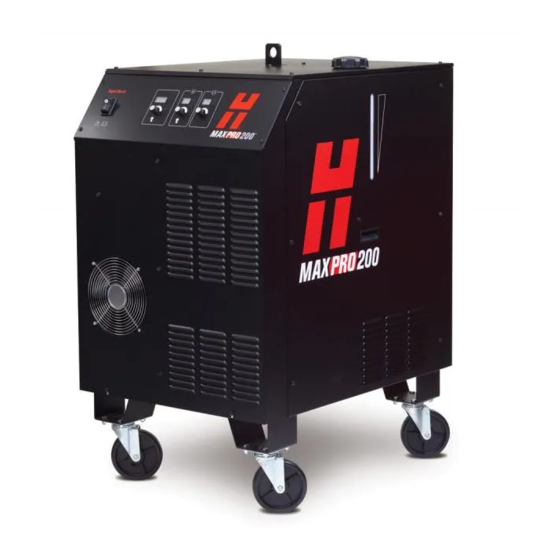
- Manuals
- Brands
- Hypertherm Manuals
- Welding System
- MAXPRO200
- Instruction manual
-
Contents
-
Table of Contents
-
Bookmarks
Quick Links
MAXPRO200
®
Instruction Manual
807700 – Revision 1
Related Manuals for Hypertherm MAXPRO200
Summary of Contents for Hypertherm MAXPRO200
-
Page 1
MAXPRO200 ® Instruction Manual 807700 – Revision 1… -
Page 2
Purchase date: _______________________________________________________________ Distributor: __________________________________________________________________ ____________________________________________________________________________ ____________________________________________________________________________ Maintenance notes: ____________________________________________________________________________ ____________________________________________________________________________ ____________________________________________________________________________ ____________________________________________________________________________ ____________________________________________________________________________ ____________________________________________________________________________ MXAXPRO200, Sensor THC, Sensor PHC, and Hypertherm are trademarks of Hypertherm, Inc. and may be registered in the United States and other countries. © 2013 Hypertherm, Inc. -
Page 3
MAXPRO200 Instruction Manual 807700 – Revision 1 English March 2013 Hypertherm, Inc. Hanover, NH 03755 USA… -
Page 4
55 11 2409 2636 Tel Hypertherm (S) Pte Ltd. 55 11 2408 0462 Fax 82 Genting Lane Media Centre Hypertherm México, S.A. de C.V. Annexe Block #A01-01 Avenida Toluca No. 444, Anexo 1, Singapore 349567, Republic of Singapore Colonia Olivar de los Padres 65 6841 2489 Tel Delegación Álvaro Obregón… -
Page 5: Table Of Contents
Additional safety information …………………………..20 Warning labels ………………………………20 Electromagnetic Compatibility (EMC) …………………23 Introduction ………………………………..23 Installation and use ……………………………… 23 Assessment of area …………………………….. 23 Methods of reducing emissions …………………………23 Mains supply ………………………………23 MAXPRO200 Instruction Manual 807700 Revision 1…
-
Page 6
The REACH regulation …………………………….32 Proper handling and safe use of chemicals ……………………..32 Fumes emission and air quality ………………………….32 Specifications ……………………….33 System description ………………………………33 General ………………………………..33 Power supply ………………………………33 Ignition console ……………………………..33 Torch ………………………………..33 Gas system ………………………………33 MAXPRO200 Instruction Manual 807700 Revision 1… -
Page 7
Premixed coolant for standard operating temperatures ………………..63 Custom Coolant mix for cold operating temperatures (below -12° C / 10° F) …………64 Custom Coolant mix for hot operating temperatures (above 38° C / 100° F) …………65 Water purity requirements …………………………. 65 MAXPRO200 Instruction Manual 807700 Revision 1… -
Page 8
Gouge profiles and metal removal rates ……………………..85 Varying the gouge profile …………………………..86 Cutting parameters ………………………………86 Mechanized consumables …………………………..86 Hand held torch consumables …………………………..86 Hand held cutting and gouging consumable selection …………………87 Mild steel ………………………………87 Stainless steel …………………………….88 MAXPRO200 Instruction Manual 807700 Revision 1… -
Page 9
Preventive maintenance ……………………………119 Power supply status …………………………….120 Sequence of operation and power supply status ……………………121 PCB block diagram …………………………….126 Error codes …………………………………127 Diagnostic functions …………………………….128 Troubleshooting table …………………………….129 Initial checks ……………………………….137 Power measurement …………………………….138 MAXPRO200 Instruction Manual 807700 Revision 1… -
Page 10
Weekly: ……………………………….. 159 Semi-annually: …………………………….159 Annually: ………………………………159 Preventive Maintenance Protocol Checklist ……………………..160 Year 1 preventive maintenance (PM) kits ……………………..161 Maintenance kits parts list …………………………161 Service parts replacement schedule ……………………….161 MAXPRO200 Instruction Manual 807700 Revision 1… -
Page 11
Mechanized torch consumable kit – 428013 ……………………178 Hand torch consumable kit – 428014 ……………………..179 Supply gas hoses ………………………………180 Oxygen …………………………………180 Nitrogen ……………………………….180 Air ………………………………….180 Recommended spare parts …………………………..181 Wiring Diagrams ……………………..183 Wiring diagram symbols …………………………..184 MAXPRO200 Instruction Manual 807700 Revision 1… -
Page 12
11 — Toxicological information …………………………201 12 — Ecological information …………………………..201 13 — Disposal considerations ………………………….. 201 14 — Transport information …………………………..202 15 — Ecological information …………………………..202 16 — Other information …………………………….202 MAXPRO200 Instruction Manual 807700 Revision 1… -
Page 13: Safety
• Wait 5 minutes after removal of power before entering • Always follow these instructions for disconnecting the enclosure to allow stored energy to discharge. power before inspecting or changing torch consumable parts. MAXPRO200 Instruction Manual 807700 Revision 1…
-
Page 14: Electric Shock Can Kill
• Provide a disconnect switch close to the power supply grounding conductor first. with properly sized fuses. This switch allows the • Each Hypertherm plasma system is designed to be operator to turn off the power supply quickly in an used only with specific Hypertherm torches. Do not emergency situation.
-
Page 15: Cutting Can Cause Fire Or Explosion
• Do not cut under water with fuel gases containing hydrogen. • Cutting under water with fuel gases containing hydrogen can result in an explosive condition that can detonate during plasma cutting operations. MAXPRO200 Instruction Manual 807700 Revision 1…
-
Page 16: Toxic Fumes Can Cause Injury Or Death
Empty and properly clean the container first. • Monitor or test the air quality at the site as needed. • Consult with a local expert to implement a site plan to ensure safe air quality. MAXPRO200 Instruction Manual 807700 Revision 1…
-
Page 17: Grounding Safety
• Tighten all electrical connections to avoid excessive heating. STATIC ELECTRICITY CAN DAMAGE CIRCUIT BOARDS Use proper precautions when handling printed circuit boards: • Store PC boards in anti-static containers. • Wear a grounded wrist strap when handling PC boards. MAXPRO200 Instruction Manual 807700 Revision 1…
-
Page 18: Compressed Gas Equipment Safety
• Keep away from the torch tip. Plasma arc comes on immediately when the torch switch is activated. • Do not hold metal near the cutting path. • Never point the torch toward yourself or others. MAXPRO200 Instruction Manual 807700 Revision 1…
-
Page 19: Arc Rays Can Burn Eyes And Skin
41 to 60 A 61 to 80 A 81 to 125 A 126 to 150 A 151 to 175 A 176 to 250 A 251 to 300 A 301 to 400 A 401 to 800 A MAXPRO200 Instruction Manual 807700 Revision 1…
-
Page 20: Pacemaker And Hearing Aid Operation
A PLASMA ARC CAN DAMAGE FROZEN PIPES Frozen pipes may be damaged or can burst if you attempt to thaw them with a plasma torch. MAXPRO200 Instruction Manual 807700 Revision 1…
-
Page 21: Dry Dust Collection Information
Note 2 – Users of Hypertherm manuals should consult and comply with all applicable federal, state, and local Consult your local “Authority Having Jurisdiction” (AHJ) laws and regulations.
-
Page 22: Laser Radiation
Exposure to the laser output can result in serious eye injury. Avoid direct eye exposure. For your convenience and safety, on Hypertherm products that use a laser, one of the following laser radiation labels has been applied on the product near where the laser beam exits the enclosure. The maximum output (mV), wavelength emitted (nM) and, if appropriate, the pulse duration is also provided.
-
Page 23: Symbols And Marks
SYMBOLS AND MARKS Your Hypertherm product may have one or more of the following markings on or near the data plate. Due to differences and conflicts in national regulations, not all marks are applied to every version of a product.
-
Page 24: Additional Safety Information
7. Ne pas enlever, détruire ni couvrir cette étiquette. Replace if it is missing, damaged, or worn (PN 110584 Rev C). La remplacer si elle est absente, endommagée ou usée (PN 110584 Rev C). MAXPRO200 Instruction Manual 807700 Revision 1…
-
Page 25
Become trained. Only qualified personnel should operate this equipment. Use torches specified in the manual. Keep non-qualified personnel and children away. Do not remove, destroy, or cover this label. Replace if it is missing, damaged, or worn. MAXPRO200 Instruction Manual 807700 Revision 1… -
Page 26
Safety MAXPRO200 Instruction Manual 807700 Revision 1… -
Page 27: Electromagnetic Compatibility (Emc)
Introduction Other supply cables, control cables, signaling and telephone cables; above, below and adjacent to the Hypertherm’s CE-marked equipment is built in compliance cutting equipment. with standard EN60974-10. The equipment should be installed and used in accordance with the information b.
-
Page 28: Maintenance Of Cutting Equipment
(nozzle for laser heads) at the same time. The operator should be insulated from all such bonded metallic components. Instruction Manual 807700 Revision 1 MAXPRO200…
-
Page 29: Warranty
Products or as to the results which Hypertherm is notified of a defect (i) with respect to the may be obtained therefrom, and all implied warranties or…
-
Page 30: Patent Indemnity
Hypertherm not in strict conformity with Hypertherm’s appropriate to defend and to hold Hypertherm harmless in specifications and in cases of designs, processes, the event of any cause of action arising from the use of the formulae, or combinations not developed or purported to products.
-
Page 31: Product Stewardship
Countries that require CE marking or have compulsory Once the product has left the Hypertherm factory, the EMC regulations must use CE versions of Hypertherm certification test marks are invalidated if any of the products with the CE marking on the data plate.
-
Page 32: Safe Installation And Use Of Shape Cutting Equipment
International Electrotechnical performing these tests, may be much greater than the standards, and shall not rely on Hypertherm in any respect benefit of periodic inspection and testing. regarding the interpretation or application of such standards.
-
Page 33: Higher-Level Systems
Higher-level systems When a system integrator adds additional equipment; such as cutting tables, motor drives, motion controllers or robots; to a Hypertherm plasma cutting system, the combined system may be considered a higher-level system. A higher-level system with hazardous moving…
-
Page 34
Product Stewardship MAXPRO200 Instruction Manual 807700 Revision 1… -
Page 35: Environmental Stewardship
The Hypertherm Environmental Specification requires used in CSA versions of Powermax and other products RoHS, WEEE and REACH substance information to be manufactured by Hypertherm that are either out of scope provided by Hypertherm’s suppliers. or exempt from RoHS are continuously being converted to RoHS compliance in anticipation of future requirements.
-
Page 36: The Reach Regulation
23 metals are listed in ASTM D 4185. An industrial Hypertherm in, on, for, or with its shape cutting equipment hygienist should be used to determine the optimum are used in very small quantities (except the coolant) and…
-
Page 37: Specifications
Specifications System description General The MAXPRO200 plasma system is designed to cut a wide range of thicknesses of mild steel, stainless steel, and aluminum. Power supply The power supply is a 200 A, 165 VDC constant-current supply. It contains the circuitry to ignite a torch, plus a heat exchanger and a pump to cool the chopper and torch.
-
Page 38
Specifications MAXPRO200 Instruction Manual 807700 Revision 1… -
Page 39: Cooling System
Shield gas Plasma gas Shield gas Plasma gas Shield gas Amperage Cutting 50 A Air or O Cutting 130 A Air or O Cutting 130 A Cutting 200 A Air or O Cutting 200 A MAXPRO200 Instruction Manual 807700 Revision 1…
-
Page 40: Power Supply
078615 CE/GOST-R 37.4 078616 50-60 37.4 078609 37.4 078617 37.4 63.5 mm (2.5 inches) 688 mm (27.1 inches) 133 mm (5.25 inches) 998 mm (39.3 inches) 927 mm (40.1 inches) 335.7 kg (740 lb) MAXPRO200 Instruction Manual 807700 Revision 1…
-
Page 41: Mechanized Torches
The minimum bend radius for the torch lead is 152.4 mm (6.0 inches) 1.02 kg (2.25 lb) 397.15 mm (15.64 inches) 279.40 mm (11.00 inches) 117.75 mm (4.64 inches) 12.70 mm (0.50 inches) 44.20 mm (1.74 inches) 46 degrees 44.20 mm (1.74 inches) MAXPRO200 Instruction Manual 807700 Revision 1…
-
Page 42: Quick-Disconnect Torch — 428027 Or 428028
435.33 mm (17.14 inches) 279.40 mm (11.00 inches) 76.98 mm (3.03 inches) 78.95 mm (3.11 inches) 12.70 mm (0.50 inches) 44.20 mm (1.74 inches) 46 degrees 57.15 mm (2.25 inches) 44.20 mm (1.74 inches) MAXPRO200 Instruction Manual 807700 Revision 1…
-
Page 43: Hand Torches
The minimum bend radius for the torch lead is 152.4 mm (6.0 inches) 0.91 kg (2.0 lb) 310.40 mm (12.22 inches) 90 degrees 44.20 mm (1.74 inches) 305.05 mm (12.01 inches) 149.10 mm (5.87 inches) MAXPRO200 Instruction Manual 807700 Revision 1…
-
Page 44: Degree Hand Torch — 420107
The minimum bend radius for the torch lead is 152.4 mm (6.0 inches) 0.91 kg (2.0 lb) 290.58 mm (11.44 inches) 65 degrees 44.20 mm (1.74 inches) 285.24 mm (11.23 inches) 238.51 mm (9.39 inches) MAXPRO200 Instruction Manual 807700 Revision 1…
-
Page 45: Installation
Claims for damage during shipment – If your unit was damaged during shipment, you must file a claim with the carrier. Hypertherm will furnish you with a copy of the bill of lading upon request. If you need additional assistance, call customer service listed in the front of this manual, or your authorized Hypertherm distributor.
-
Page 46: Placement Of System Components
To prevent leaks in the system, tighten all gas connections as shown below. Torque specifications Gas or water hose size kgf-cm lbf-in lbf-ft Up to 10 mm (3/8 in) 8.9–9.8 75–85 6.25–7 12 mm (1/2 in) 41.5–55 360–480 30–40 MAXPRO200 Instruction Manual 807700 Revision 1…
-
Page 47: Supply Gas Hoses
Installation System components Power supply Torch Cable and lead Torch lead Work lead CNC interface cable Supply gas hoses Customer supplied power cable Main power cable MAXPRO200 Instruction Manual 807700 Revision 1…
-
Page 48: Recommended Grounding And Shielding Practices
Note: The grounding practices in this section have been used on many installations with excellent results, and Hypertherm recommends that these practices be a routine part of the installation process. The actual methods used to implement these practices may vary from system to system, but should remain as consistent as possible.
-
Page 49
9. Each Hypertherm component, as well as any other CNC or motor drive cabinet or enclosure, must have a separate ground cable to the common (star) ground on the table. This includes the ignition console, whether if it is bolted to the plasma system or to the cutting table. -
Page 50
Cable to the cutting table ground bus Ground cables from components on the gantry The following diagram shows an example of grounding the components in a plasma cutting system. MAXPRO200 Instruction Manual 807700 Revision 1… -
Page 51
CNC chassis Table ground bus bar Torch height control module (ArcGlide, CommandTHC) Gantry ground bus bar System-specific component such as a cooler or chiller Torch height control lifter (ArcGlide, Sensor THC, Sensor PHC, or other) MAXPRO200 Instruction Manual 807700 Revision 1… -
Page 52: Placement Of The Power Supply
Do not place any filter device over the air intake locations, which reduces cooling efficiency and VOIDS THE WARRANTY. • Do not place the power supply on an incline greater than 10° to prevent it from toppling. MAXPRO200 Instruction Manual 807700 Revision 1…
-
Page 53: Torch Lead Connections
2. Connect the CPC connector to the CPC receptacle. MAXPRO200 Instruction Manual 807700 Revision 1…
-
Page 54
To disconnect a fitting, push the connector-collar and hose toward the fitting, hold the collar in place and pull the hose away from the fitting. 3. Connect the coolant return hose (red). 4. Connect the plasma gas hose (black). MAXPRO200 Instruction Manual 807700 Revision 1… -
Page 55
5. Connect the pilot arc/shield gas hose (blue). 6. Connect the negative lead/coolant supply hose (blue with green tape). MAXPRO200 Instruction Manual 807700 Revision 1… -
Page 56: Work Lead Connections
23 m (75 feet) 223338 30 m (100 feet) Remove the first nut and washer from the work lead terminal and use it to secure the work lead to the terminal. Lower frame of work table (typical) MAXPRO200 Instruction Manual 807700 Revision 1…
-
Page 57: Torch Connections
Note: The connections between the straight torch main body and the torch leads are identical to the connections between the quick-disconnect receptacle and the torch leads. Align the quick disconnect receptacle, or the straight torch main body, to the torch leads and secure using the push-to-connect fittings. Connect to torch lead MAXPRO200 Instruction Manual 807700 Revision 1…
-
Page 58: Connect The Torch To The Quick-Disconnect Receptacle
The o-rings should look shiny, but there should not be any excess or built-up lubricant. Be certain that there is no space between the torch body and the o-ring on the quick-disconnect. MAXPRO200 Instruction Manual 807700 Revision 1…
-
Page 59: Torch Mounting And Alignment
Note: The bracket should be as low on the torch sleeve as possible to minimize vibration at the tip of the torch. Torch alignment To align the torch at right angles to the workpiece, use a square as shown above. MAXPRO200 Instruction Manual 807700 Revision 1…
-
Page 60: Cnc Interface Cable
J6 on the control board. Open the clips by depressing the release tab, and add the CNC cable to the wires that are already present in the clip. See the figure on the next page. MAXPRO200 Instruction Manual 807700 Revision 1…
-
Page 61
Installation CNC cable routing and connection to control board from the To J6 on the control board MAXPRO200 Instruction Manual 807700 Revision 1… -
Page 62: Remote On/Off Switch (Provided By Customer)
2. Remove the jumper wire between terminal 1 and terminal 2. Use a sturdy tool to depress the corresponding orange release buttons on the spring clamp connector 1 2 3 4 5 6 7 MAXPRO200 Instruction Manual 807700 Revision 1…
-
Page 63
Note: The power switch on the power supply must be in the ON position for the remote switch to function and the remote switch must be in the ON position (closed) for the power switch on the power supply to function. MAXPRO200 Instruction Manual 807700 Revision 1… -
Page 64: Power Requirements
(4 AWG) 13.3 mm (6 AWG) 600 VAC 36 amps 50 amps 13.3 mm (6 AWG) 8.3 mm (8 AWG) Note: Wire AWG recommendations came from Table 310-16 of the National Electric Code Handbook (USA). MAXPRO200 Instruction Manual 807700 Revision 1…
-
Page 65: Line Disconnect Switch
Wire sizes vary based on the temperature rating of the cable insulation and the distance of the unit from the main box. Use a 4-conductor Type SO input power cable with a conductor temperature rating of 60° C (140° F) or 90° C (194° F). Installation must be performed by a licensed electrician. MAXPRO200 Instruction Manual 807700 Revision 1…
-
Page 66: Connect The Power
North American wire colors European wire colors U = Black U = Black V = White V = Blue W = Red W = Brown (PE) Earth ground = Green/yellow (PE) Earth ground = Green/yellow Ground MAXPRO200 Instruction Manual 807700 Revision 1…
-
Page 67: Torch Coolant Requirements
Premixed coolant for standard operating temperatures Use Hypertherm premixed coolant (028872) when operating in a temperature range of -12° C to 40° C (10° F to 104° F). Refer to the custom coolant mix recommendations, if temperatures during operation are ever outside of this range.
-
Page 68: Custom Coolant Mix For Cold Operating Temperatures (Below -12° C / 10° F)
Mix 100% propylene glycol (028873) with the premixed Hypertherm coolant (028872) to increase the percentage of glycol in the premixed Hypertherm coolant. The 100% glycol solution can also be mixed with purified water (see the chart below for water purity requirements) to achieve the required protection from freezing.
-
Page 69: Custom Coolant Mix For Hot Operating Temperatures (Above 38° C / 100° F)
μS/cm mΩ-cm (ppm of NaCl) (gpg of CaCO2) at 25° C (77° F) at 25° C (77° F) Pure water (for reference 0.055 18.3 only) Maximum purity 0.206 0.010 Minimum purity 0.054 0.43 Maximum potable water 1000 0.001 (for reference only) MAXPRO200 Instruction Manual 807700 Revision 1…
-
Page 70: Fill The Power Supply With Coolant
4. Add coolant to the power supply until the tank is system and add coolant to the tank until it is full again. full and replace the filler cap. Repeat steps 2 and 3 until no error is displayed. MAXPRO200 Instruction Manual 807700 Revision 1…
-
Page 71: Connect The Supply Gases
2. Remove the Air fitting 015012 (1/4 inch NPT X #6 MALE) from the filter/regulator. Install an 015103 adaptor to use the nitrogen supply gas hose offered by Hypertherm. b. Use the 1/4 inch NPT Female port from which the air fitting was removed to connect a user supplied N supply gas hose.
-
Page 72
4. Connect only filtered and regulated oxygen to the plasma gas Inlet. See Gas regulators on page 72 for a suitable oxygen regulator. Note: An oxygen fitting kit (428054) with the parts described below is available from Hypertherm. There are several options for connecting the oxygen supply gas line: Remove the 015811 fitting and put on an 015009 fitting (user must order the part. -
Page 73
8 mm (5/16 inch) tubing that you removed from the plasma gas Inlet. Remove the plasma gas tubing and 8 mm (5/16 inch) fitting (015811) and connect to the 1/4 inch NPT female threads. 015811 MAXPRO200 Instruction Manual 807700 Revision 1… -
Page 74
Remove the bushing and fitting to connect to 1/4 inch “G” female threads. 015810 051811 5. Reconnect the air supply. 6. Set the gas pressure regulators. See Setting the supply gas regulators on page 71. MAXPRO200 Instruction Manual 807700 Revision 1… -
Page 75: Gas Requirements
005, “Flow gas at full pressure”. Set all supply regulators to a system inlet pressure of 6.2 bar (90 psi). 4. Press and release the current selection knob until the amps icon is illuminated. MAXPRO200 Instruction Manual 807700 Revision 1…
-
Page 76: Gas Regulators
Use a high-quality, 2-stage, gas regulator to maintain consistent gas supply pressure from high pressure gas cylinders. The high-quality gas regulators listed below are available from Hypertherm and meet U.S. Compressed Gas Association (CGA) specifications. In other countries, select gas regulators that conform to national or local codes.
-
Page 77: Supply Gas Plumbing
CUTTING WITH OXYGEN CAN CAUSE FIRE OR EXPLOSION Cutting with oxygen as the plasma gas can cause a potential fire hazard due to the oxygen-enriched atmosphere that it creates. As a precaution, Hypertherm recommends that an exhaust ventilation system be installed when cutting with oxygen.
-
Page 78: Supply Gas Hoses
7.5 m (25 ft) 024120 45 m (150 ft) 024211 10 m (35 ft) 024124 60 m (200 ft) 024112 15 m (50 ft) 024764 75 m (250 ft) 024763 20 m (65 ft) MAXPRO200 Instruction Manual 807700 Revision 1…
-
Page 79: Operation
3. Replace consumable parts. See Install and inspect consumables on page 90 for details. 4. Make sure that the torch is perpendicular to the workpiece. Shield Swirl ring Nozzle retaining cap Electrode Nozzle Torch main body (quick-disconnect torch shown) MAXPRO200 Instruction Manual 807700 Revision 1…
-
Page 80: Controls And Indicators
Operation Controls and indicators Control panel descriptions Power switch 3-digit display area Current selection knob 2-digit plasma display area Plasma gas knob 2-digit shield display area Shield gas knob MAXPRO200 Instruction Manual 807700 Revision 1…
-
Page 81: Power Supply Operation
The displays show the set values when idle. • A blinking red dot appears in the bottom right corner of each display when the parameters have been changed from the default setting. MAXPRO200 Instruction Manual 807700 Revision 1…
-
Page 82: 3-Digit Display Functions
This white lamp illuminates when the plasma start signal is given and 6 Plasma start lamp stays illuminated until the start signal is removed. 7 Arc transfer lamp This green lamp illuminates when the arc transfers to the workpiece. MAXPRO200 Instruction Manual 807700 Revision 1…
-
Page 83: Choosing A Cutting Process
You can return to the default setting by pressing and releasing the knob until you return to the original gas selection. Note: The example shown below is the 50 amp, mild steel, air/air process. See the cut chart for details. MAXPRO200 Instruction Manual 807700 Revision 1…
-
Page 84: Handheld Cutting
2. Hold the torch lightly on the metal or just off the metal and drag the torch across the metal. The arc transfers once the torch is within 6 mm (1/4 inch) of the workpiece. MAXPRO200 Instruction Manual 807700 Revision 1…
-
Page 85: Piercing
3. When the pierce is complete, proceed with the cut. MAXPRO200 Instruction Manual 807700 Revision 1…
-
Page 86: Gouging
Keep a small distance between the torch tip and the molten metal to avoid reducing consumable life or damaging the torch. Note: Changing the torch’s angle changes the dimensions of the gouge. Feeding into the gouge MAXPRO200 Instruction Manual 807700 Revision 1…
-
Page 87: Gouging Techniques
Operation Gouging techniques Straight gouging Straight gouge Weaving gouge MAXPRO200 Instruction Manual 807700 Revision 1…
-
Page 88: Side Gouging
Operation Side gouging Side gouge Weaving gouge MAXPRO200 Instruction Manual 807700 Revision 1…
-
Page 89: Gouge Profiles And Metal Removal Rates
Typical gouge profile for 200A, O Metal removal rate on mild steel – 20.5 Kg/hr (45 lbs/hr) Speed 1270 mm/min (50 ipm) Stand off 12.7 mm (0.5 inch) Angle º 10.4 mm (0.41 inches) 5.4 mm (0.21 inches) MAXPRO200 Instruction Manual 807700 Revision 1…
-
Page 90: Varying The Gouge Profile
Cutting parameters The cut charts for the MAXPRO200 show the consumable parts, cutting speeds, and the gas and torch settings required for each process, allowing for differences in the lead length. These parameters are used for cutting with both mechanized and handheld torches, the consumable part numbers listed with each cut chart are specific to mechanized torches.
-
Page 91: Hand Held Cutting And Gouging Consumable Selection
The following sets of consumables are intended to be used with handheld torches for cutting mild steel, stainless steel, and aluminum. You can use the cutting parameters detailed under Cut charts on page 101 with the MAXPRO200 handheld torches as long as you use the following consumables for each process.
-
Page 92: Stainless Steel
200 A Air Plasma Air Shield 420058 220935 420044 220488 220937 200 A N2 Plasma N2 Shield 420058 220935 420044 220488 020415 200 A Gouging Air Plasma Air Shield 420067 220935 420066 220488 220937 MAXPRO200 Instruction Manual 807700 Revision 1…
-
Page 93: Aluminum
200 A Air Plasma Air Shield 420058 220935 420044 220488 220937 200 A N2 Plasma N2 Shield 420058 220935 420044 220488 020415 200 A Gouging Air Plasma Air Shield 420067 220935 420066 220488 220937 MAXPRO200 Instruction Manual 807700 Revision 1…
-
Page 94: Install And Inspect Consumables
4. Install the 5. Install the electrode into ring into the nozzle and swirl nozzle retaining shield onto the the torch head nozzle ring into the cap onto the nozzle retaining nozzle retaining torch head MAXPRO200 Instruction Manual 807700 Revision 1…
-
Page 95: Inspect Consumables
In general, replace the electrode when the pit depth is the electrode as a set the emitter wears 1 mm (0.04 in.) or greater. Emitter O-rings: Damage Replace the o-ring Lubricant Apply a thin film of silicone lubricant if the o-rings are dry MAXPRO200 Instruction Manual 807700 Revision 1…
-
Page 96: Torch Maintenance
Maintenance kit Even with proper care, the o-rings at the rear of the torch will need to be replaced periodically. Hypertherm provides a quick-disconnect torch maintenance kit (228780) with replacement parts. The kit should be kept in stock and be used as part of your routine maintenance schedule.
-
Page 97: Torch Connections
Torch main body Quick-disconnect receptacle Shield gas Pilot arc Coolant return Plasma gas Coolant supply Straight torch Plasma gas Coolant supply (also contains the negative lead) Shield gas (also contains the pilot arc lead) Coolant return MAXPRO200 Instruction Manual 807700 Revision 1…
-
Page 98: Replace The Torch Water Tube
4. Apply a thin film of silicone lubricant on the o-ring, and install a new water tube. The o-ring should look shiny, but there should not be any excess or built-up lubricant. 5. Replace consumables. See Install and inspect consumables on page 90. MAXPRO200 Instruction Manual 807700 Revision 1…
-
Page 99: Common Cutting Faults
The metal being cut is too thick for the selected amperage. • Gouging consumables are installed instead of drag-cutting consumables. • The work clamp is not attached properly to the workpiece. • The gas pressure or gas flow rate is too low. MAXPRO200 Instruction Manual 807700 Revision 1…
-
Page 100: Optimizing Cut Quality
Reduce the cutting speed during the final part of the cut. • Stop the arc before the part is completely cut to allow completion of the cut during the ramp-down. • Program the path of the torch into the scrap area for ramp-down. MAXPRO200 Instruction Manual 807700 Revision 1…
-
Page 101: Additional Factors Of Cut Quality
A negative cut angle results when more material is removed from the bottom of the cut. Cause Solution Negative angle The torch is too low. Increase arc voltage to raise the torch Square Positive angle The torch is too high. Decrease arc voltage to lower the torch. MAXPRO200 Instruction Manual 807700 Revision 1…
-
Page 102: Dross
For mechanized applications the torch must not touch the workpiece while piercing or cutting. For hand held applications the shield can be touching the workpiece to provide stability during cutting. MAXPRO200 Instruction Manual 807700 Revision 1…
-
Page 103: Estimated Kerf-Width Compensation
Estimated kerf-width compensation The kerf widths in the following charts are for reference. Differences between installations and material composition may cause actual results to vary from those shown in the tables. Metric Thickness (mm) Mild steel 50A Air / Air 1.72 1.51 1.46…
-
Page 104: English
English Thickness (inches) Mild steel 0.018 0.020 0.024 0.030 0.036 0.048 0.060 0.075 0.105 0.125 0.135 3/16 5/16 1-1/4 1-1/2 1-3/4 50A Air / Air 0.069 0.065 0.061 0.056 0.060 0.064 0.063 0.059 0.056 0.058 0.063 50A O2 / Air 0.054 0.053 0.053 0.053 0.054 0.055 0.055 0.056 0.057 0.063 0.059…
-
Page 105: Cut Charts
Operation Cut charts The following cut charts for the MAXPRO200 show the consumable parts, cutting speeds, and the gas and torch settings required for each process, allowing for differences in the lead length. While you can use these parameters for cutting with both mechanized and handheld torches, the consumable part numbers listed with each cut chart are specific to mechanized torches.
Ошибки на дисплее источников Hypertherm, вопросы по источникам — FAQ
Ошибка источника powermax 125 с кодами 0-12 и 0-20 свидетельствует о низком давлении воздуха, или не стабильности (пульсациях, просадках) давления при входе в источник.
Какие могут быть причины?
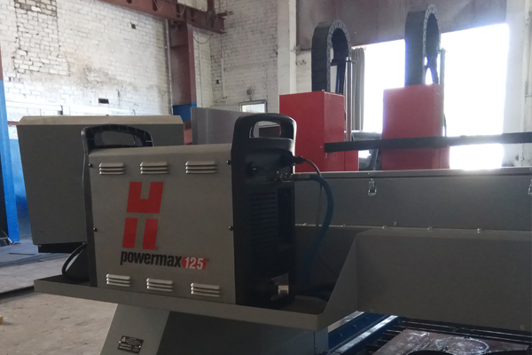
1. Маленькая производительность компрессора
2. Засор фильтра
3. Если изначально не было дополнительной системы фильтрации воздуха, то возможен выход из строя регулятора давления воздуха (клапана).
Powermax 125 может работать на ПВ 100% разрезая 35 мм стали У8?
Скорее всего сможет, но только с края листа и небольшой скоростью.
ошибка 022 , резак вообще не включается
Код ошибки 0-22 означет, что нет воздуха на входе в источник, возможно давление маленькое или фильтр-элемент давно не меняли
Раньше была ошибка 0-12 и 0-20, а теперь совсем не зажигается дуга ошибка 0-30 и в самом источнике слышно сильно шипит воздух, то есть воздух не подается на плазматрон
Есть вариант замерзания конденсата, на выходе из компрессора, или где-то в фильтре, так же возможно неисправен датчик или содинение с датчиком в плазмотроне (красный провод), возможно неисправен клапан:
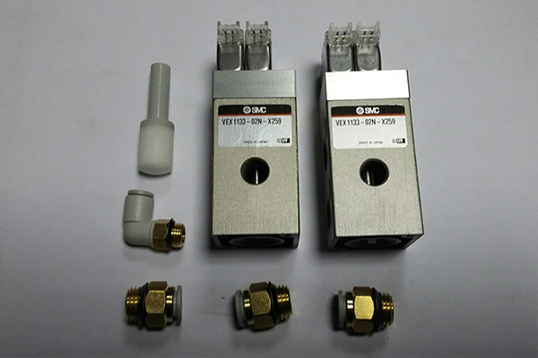
почему гнет металл???, после того как там плазматрон поработал? то есть. Получается его гнет и плазматрон не над ним идет а уже по нему ( треться защитным экраном)????это я про 105 гипер.
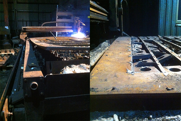
Наиболее вероятно, что тут дело в металле, точно не в настройках, я просто молчу про maxpro200 на ней еще хуже где там очень много тепла она отдает от реза,но сейчас она сломалась, плата возбуждения дуги сдохла и это то только пол, года прошло! Видимо какой то ингредиент не добавлют, либо технология проката нарушена
Подскажите, пожалуйста. Есть источник Powermax 105, вышел из строя электромагнитный клапан (228882). Можно ли его заменить на 228687 ? В паспорте написано, что они взаимозаменяемые, но все дилеры говорят, что 228687 подходит только на Powermax 105.
Комплект 228687 обновлен, теперь он включает в себя два воздушных шланга 19,7см для 65/85 и 30,5см для 105/125 Все системы с серийными номерами 105-018105 и выше, 125-003925 и выше оснащены новым клапаном.
hypertherm powermax 65-й при прожиге нескольких отверстий в одной детали, поднимается вверх от листа, сантиметров на 5 и продолжает резать. А через 3-4 секунды выключается?
Скорее всего либо скорость выбрана большая, либо индукционое напряжение плохо заземлено.
Так же стоит помотреть сами контакты на резаке и все (что с ним движеться в верх и в низ), возможно требуется корректировка времени прожига, бывает металл сразу в сопло попадает и оно поднимается вверх, по показаниям датчика.
Как избежать ошибок по воздуху? Очень часто приходится менять электромагнитный клапан. Появляется ошибка 0-30 это первая причина (но ещё немного можно подождать замены клапана), потом дальше начинает появляться 0-12 при резке (предупреждение) и далее часто возникает 0-20 полная остановка
чтобы этого не случалось надо дополнительно приобретать хороший влагомаслоотделитель, который существенно продлит срок жизни механики по воздуху:
Очень быстро сгорает сопло. Резак механический, по идее быстрее в этом случае должен изнашиваться электрод, но у меня так. Режу 6-ку соплом на 85А током 65 ампер. Метров 30 режет, прожигов 60 примерно и сопло выгорает. Воздух сухой, стоят самодельные большие колбы с силикогелем сухим (предварительно прркаленным), фильтр тонкой очистки фирменный (с синим бумажным фильтром в средине) ну и в аппарате фильтр тонкой очистки новый тоже. Давление воздуха 7.5 атм. То есть всё вроде в норме. Все детали оригинальные Hypertherm.
Сильно влияет на расход электродов — расстояние от сопла до заготовки, заземление источника, неудачные пробои металла в неоптимальном режиме, скорее всего требуется уменьшить время прожига, так же стоит исключить контакт уже вырезанных фрагментов заготовки и плазмотрона, после реза.
Начинаю работать все идёт хорошо, где-то после 200 прожигов начинают постоянно вылетать ошибки 44(низкое давление плазмообразующего газа) 53(низкое давление защитного газа) вылетают с переодичностью после 7-9 прожигов.
Давление падает, при долгой резке — тут стоит подумать о замерзании элементов подачи, стоит или поставить систему подогрева газа, или утеплить помещение в котором проходит резка. При температурах ниже +10С такое бывает на больших объёмах, встречается даже подмерзание сервопривода сопла.
Павермакс 105, очень часто выддает ошибки012 и 030, так то вроде все работаетвпорядке… смотрел по форуму, пишут что давления воздуха слабое, кто говорит что что то с расходниками не пойму… за день раз 30 вылетает ошибка. я на плазме работаю совсем не давно не опытный, подскажите ппожалуйста!
На задней стенке источника (аппарата) стоит фильтр с колбой, в нем меняли фильтр элемент (желтовато-грязного цвета цилиндрик) это расходник его надо менять. Если его не меняют, то вся грязь идет внутрь через регулятор давления, если модель старая то это черная коробчка, если новая то это регулятор типа SMC, как правило больше проблем не возникает с воздухом. При условии нормального давления воздуха на входе или с неисправностью регулятора давления либо датчика давления, чаще всего регулятора, ни то ни другое ремонту не подлежит — только замена.
max200 ,сгорел плазмотрон поставили новый и из сопла при включении брызжит охлаждающая жидкость но при этом она режит(может плазмотрон бракованный)
Проверьте уплотнители резиновые, их там достаточно, возможно повреждена какая-то из резинок.
Подскажите номер заказа электромагнитного клапана. у меня есть этот 228882 но он устаревшего типа
Обновленный номер 228687
Система режет металл пару секунд а потом останавливается и выдает ошибку 0-60, в чем может быть причина?
С высокой вероятностью пропала одна фаза в питающем кабеле, проверьте вводный автомат
подскажите пожалуйста почему могут получатся такие отверстия источник hypertherm 105,давление 5,4 стоит,85 ампер,скорость 350 мм/м.металл 8 мм,отверстия овальные,на выходе ещё хуже
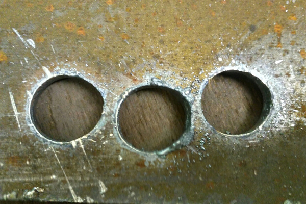
Геометрия отверстий, чаще всего связана с геометрией станка и координатной системой. Качество резки зависит от скорости резки, высоты резака и работы контроля высоты. Бывает, что нет соосности расходников или имеются повреждения расходников. Чтобы начать диагностику нужно заменить для начала все расходники, поставить оригинал, далее проверяем перпендикулярность резака относительно листа угольником, далее почистите зубчатую рейку и направляющие, проведите калибровку, выставьте значения параметров резки в соответствии с технологическими картами источника Powermax (они даны как рекомендации) и далее проводите настройку, подбирая режим.
Подскажите как можно проверить электромагнитный клапан hipertherm 105,постоянная вскакивает ошибка 0-12,можно ли грешить на него?
К сожалению 100% вам никто не скажет, через экран монитора клапан это или нет. Эта ошибка может указывать и на клапан, и на фильтр и на расходники, но, как показывает практика, ошибки связанные с воздухом, чаще всего возникают из-за загрязнения фильтр элемента, а он в свою очередь уже засорился и грязь погнал в клапаны, и ошибки эти чаще всего возникают осенью и весной, т.к. воздух сырой идет с компрессора.
Возможно ли разобрать и починить электромагнитный воздушный клапан SMC?
Разобрать возможно, но ремонтопригодность под большим вопросом. Надежным такой ремонт назвать сложно, ремкомплекты для ремонта в продаже не встречаются, механизм клапана и характер повреждений, которые обычно встечаются таков, что ремонт используется скорее как крайняя мера, которая может незначительно и временно улучшить ситуацию. Клапан представляет собой регулятор давления с электронным управлением. Электронный блок аппарата управляет двумя электромагнитными клапанами, которые устанавливают давление на мембрану (поршень). Последняя сравнивает установленное давление с выходным и нагнетает или сбрасывает уровень давления в выходном порту.
Чернеет электрод и сопло, раньше такого не замечал,и сильно греются,это нормально?источник гипер повермакс 105
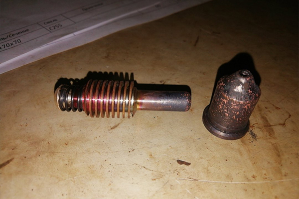
практически любой металл меняет цвет, в случаях если он окисляется, а это возможно или при высоких температурах (резка на максимальном токе и малой скорости) или при химической реакция от внешнего воздействия. Либо металл покрывается продуктами сгорания из вне, например при сгорании масла из компрессора
подскажите пожалуйста, источник повермакс 105, стол 2х6. Вырезал два отверстия показывалась ошибка 0-30, менял расходники, снова 2 отверстия вырежет и показывает ошибку 0-30. Потом стал показывать ошибку 0-50 и сам источник когда выключешь его, табло продолжает секунд 5 гореть. В чем дело?? расходники новые не заменен только кожух и завихритель.
Для начала открываем инструкцию на Powermax там указаны все ошибки и примерные указания по причине их возникновения и методы проверки. 90% ошибок, это ошибки связанные с плохими расходниками и качеством воздуха.
Если система поджигает дугу и гаснет, с разной периодичностью показывая различные ошибки, то скорее всего это грязный фильтрующий элемент и как следствие плохая работа воздушного клапана — и то и другое под замену, ремонту (промывка и чистка) не поддаётся, даже если поможет то не надолго.
Если ошибка появляется при смене расходников и расходники не оригинал — то смотрите резьбу на головке резака и концевик, головку под замену, возможно и микровыключатель тоже придется заменить.
Система HPR 400 выдает ошибку105, при открытой крышке видно, что на первом инверторе не горят светодиоды, прозвонка первичной обмотки трансформатора показала обрыв, блок был заменен на запасной, светодиоды индикации загорелись, но опять 105 ошибка, поменяны местами первый и второй инвертора, ошибка остаётся 105, поменяны местами датчики тока — ошибка осталась 105,на плате ввода-вывода был обноружен сгоревший двухсторонний быстрый диод 35 нсек, поменян на 2 односторонних быстрых 65 нсек(незначительная разница).
На плате ввода вывода больше гореть не чему, остались только несколько резисторов и кондёров, резисторы проверены, всё в номинале. И реле нормально-замкнутое. При включении всё должно работать, но не работает.
При запуске источник начинает по очереди тестировать инверторы (они — же чопперы)1-3-2-4. Чопперы по очереди включаются на очень короткий промежуток времени и подают питание на плату ввода-вывода, тестируются не по напряжению, а по току.
Между чоппером и платой ввода-вывода стоит токовая петля с усилителем (токовые клещи не успевают зафиксировать ток), ток должен быть не менее 10 ампер т.е. напряжение с чоппера 360В/10А=<36 Ом-нагрузка. Нагрузки 36 Ом на плате нет, сделали вывод, что конденсатор 350 мкф в момент заряда качает те самые 10А за доли секунды, потом первый чоппер отключается, конденсатор через параллельно подключенные резисторы разряжается, и цикл повторяется со следующим чоппером.
— Так происходит если всё нормально, если через какой-то чоппер не выдает необходимые 10А, то система отключается и выдаёт соответствующую ошибку.
На одном из чёпперов вышла из строя плата управления двумя транзисторами (была заменена), она скорее всего унесла за собой эти самые два транзистора и они оказались постоянно открытыми, и постоянно накачивали тот самый конденсатор на 350mkF на плате ввода -вывода, не давая потечь необходимым 10А через токовые петли. Система не регистрировала на плате ввода-вывода необходимый ток и выдавала ошибку о неисправности первого инвертора. Поиски поломки. Были отключены провода со всех инверторов и мультиметром проверялось напряжение на выходе с инвертора при замыкании главного пускателя.
Оказалось что напряжение на первом и на четвёртом одновременно появляется(должно появиться только на одном), но на первом пропадает сразу после выключения главного пускателя, а на четвёртом медленно падает до нуля в течении 30 секунд, и случайно на плате управления транзисторами (на чоппере) был выявлен перегрев микросхем стабилизаторов напряжения типа наших КРЕН-ок (очень горячие).
Вся эта плата была распаяна на радиодетали, поменяны все микросхемы, и произведен тестовый запуск снова — ошибка та-же, стабилизаторы напряжения греются, были заказаны транзисторы, заменены их и всё запустилось.
Источник HYPERTHERM 65 ошибка 0-99.
Заменен электронный датчик давления — всё заработало.
источник hpr 130 xd,станок мультикам 3000 станок пишет ошибку 105, как сказали, неисправен какой-то датчик газов в источнике
Низкий ток на CS1.
Значение тока менее 10 ампер зафиксировано датчиком тока 1
схожая ошибка, её диагностика описаны выше. Скорее всего потребуется ремонт электронных составляющих системы.
Вы можете скачать у нас: Руководство пользователя Hypertherm HyPerfomance 130 XD ~28Мб
hypertherm Hypertherm Plasma HPR260, защитный наконечник, колпачек поплавился…в нем образовались отверстия… Это случилось после тестов резки металла толщиной 16мм. (сталь) на токе 130А. повторюсь резак новый, фирменный от hypertherm Torch – 128818
Проверьте работу системы охлаждения, работу помпы, целостность и отсутствие воздуха в трубках, убедитесь, что залита оригинальная жидкость Hypertherm.
Если причину не удастся устранить самостоятельно, рекомендую обратиться в наш сервисный центр по телефону 88007757857 для более детальной консультации, посредством видео связи, предоставления дополнительных фото
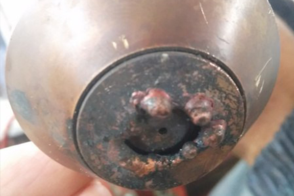
Какой стол для системы плазменной резки посоветуете? Воздушный? Водяной? Секционная вытяжка? Подскажите наиболее эффективный рабочий вариант под мощность макспро200, три на полтора метра стол
Как показывает практика, наиболее эффективен водоналивной стол. Он практически полностью поглащает дым, образующийся выдуваемым расплавленным металлом.
Дополнительная вытяжка если и нужна, в нагруженных режимах работы, то нагрузка на неё оказывается не велика.
Пример работы водоналивного стола можно увидеть на видео:
- Лазерная резка
- Машины плазменной резки
- Источники для резки с ЧПУ
- Расходные материалы
- Программное обеспечение
Инструкция по эксплуатации системы MAXPro200 от Hypertherm содержит всю необходимую информацию для эффективной и безопасной работы с данным оборудованием, включая сведения об установке, электромагнитной совместимости, гарантийных обязательствах производителя и техническом обслуживании.
![]() MAXPro200 инструкция по эксплуатации
MAXPro200 инструкция по эксплуатации
Популярные товары
-
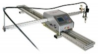
Steel Tailor Power
Портативные системы -
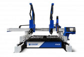
Машина плазменной резки Sapphire
Машины плазменной резки -

Машина плазменной резки Jantar
Машины плазменной резки -
Powermax105 SYNC
Установки для ручной резки -
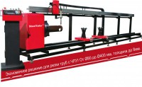
Станок для резки труб с ЧПУ TubeTailor II
Машины для резки труб -
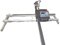
Legacy XP
Портативные системы -

Swift-CUT — портативная 3-х координатная система резки с ЧПУ
Машины плазменной резки -

Galaxy SQL4
Машины плазменной резки -
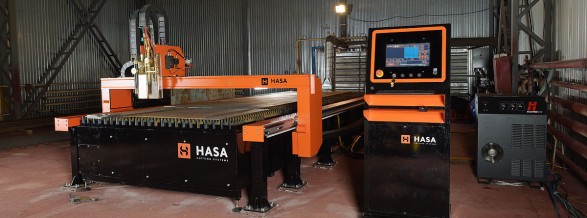
Плазменная машина термической резки HASA
Машины плазменной резки -
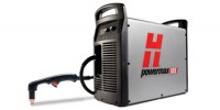
Powermax 105
Установки для ручной резки -
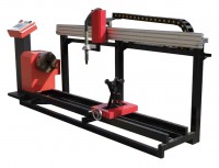
Установка термической резки труб Steel Tailor Tube I
Машины для резки труб -
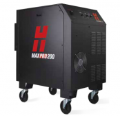
MAXPRO200
Установки для ручной резки -

Uppercut
Установки для ручной резки -

Powermax 125
Установки для ручной резки
<
>
Наши преимущества
![]()
![]()
Шоу-рум
Представлено оборудование в различных ценовых сегментах и с разными конструктивными
особенностями
![]()
Тест-драйв
Возможность познакомиться с технологией резки, собственноручно протестировав
интересующую Вас модель оборудования
![]()
![]()
Гарантия качества
Мы поставляем только качественный, оригинальный и сертифицированный товар
![]()
Лизинговые программы
Позволят привлечь внешнее финансировать и получить значительные финансовые льготы для
Вашего предприятия
![]()
Монтаж оборудования
Монтаж станков и ввод их в эксплуатацию — гарантия бесперебойной работы
оборудования
![]()
Надежный сервис
Авторизованный сервисный персонал компании обеспечит оперативный отклик на Ваше
обращение
![]()
Приложение B. Протокол обмена данными с ЧПУ
HPR260XD Auto Gas –
80635J, 2-я редакция
b-21
Коды ошибок
Идентификатор Название
Описание
000
NO ERROR (Ошибки отсутствуют)
Система готова к работе.
009
FLOW SWITCH TEST
(тест переключателя потока)
Когда насос повторно запускается после простоя (30 минут без пускового
сигнала), системой будет выполнен тест переключателя потока, чтобы
убедиться в достаточности потока до зажигания резака.
011
NO_ACTIVE_PROCESS
(нет активного процесса)
Источник тока получает неверное значение тока от ЧПУ.
012
TEST IN PROGRESS (Идет тест)
Активен один из режимов тестирования газа.
013
TEST PASSED (Тест пройден)
Тест успешно выполнен.
014
CUT GAS CHANNEL #1 FAIL
(Отказ канала режущего газа № 1)
Давление газа падает на канале № 1, что является признаком утечки.
015
CUT GAS CHANNEL #2 FAIL
(Oтказ канала режущего газа № )
Давление газа падает на канале № 2, что является признаком утечки.
016
PLASMA RAMP-DOWN FAIL
(Отказ плавного выключения
плазмообразующего газа)
Выход насоса превысил 200 фунтов на квадратный дюйм.
017
SHIELD RAMP-DOWN FAIL
(Отказ плавного выключения
защитного газа)
Давление защитного газа не уменьшилось за отведенное время.
018
PUMP OVER PRESSURE
(Избыточное давление насоса)
Выход насоса превысил 13,79 бар.
020
NO PILOT ARC
(Отсутствует вспомогательная дуга)
Не выявлен ток от инвертора на блоке зажигания до истечения срока в 1
секунду.
021
NO ARC TRANSFER
(Отсутствует перенос дуги)
Не обнаружен сигнал переноса по истечении задержки в 500 миллисекунд.
024 Первичный
224 Вторичный
LOST CURRENT CH1
(Потеря тока на инверторе 1)
После переноса происходит потеря сигнала тока инвертора.
025 Первичный
225 Вторичный
LOST CURRENT CH2
(Потеря тока на инверторе 2)
После переноса происходит потеря сигнала тока инвертора.
026 Первичный
226 Вторичный LOST TRANSFER (Потеря переноса) После переноса происходит потеря сигнала переноса.
027 Первичный
227 Вторичный LOST PHASE (Потеря фазы)
Когда включен главный замыкатель, отсутствует ввод «phase OK
(фаза ОК)».
028 Первичный
228 Вторичный
LOST CURRENT CH3
(Потеря тока на инверторе 3)
После переноса происходит потеря сигнала тока инвертора.
030
GAS SYSTEM ERROR
(Ошибка газовой системы)
Возник отказ в газовой системе.
031 Первичный
231 Вторичный START LOST (Потеря зажигания)
Пусковой сигнал был снят до достижения установившегося состояния.
032
HOLD TIMEOUT (Истекло время
ожидания зажигания)
Сигнал удержания был задействован более 60 секунд.
033
PRE CHARGE TIMEOUT (Истекло
время ожидания наполнения газом)
Системе управления подачей газа не удалось наполнить газовые линии
до достижения нужного давления.
034 Первичный
234 Вторичный
PRE CHARGE TIMEOUT (Истекло
время ожидания наполнения газом)
Системе управления подачей газа не удалось наполнить газовые линии
до достижения нужного давления.
042
LOW NITROGEN PRESSURE
(Низкое давление азота)
Давление азота ниже нижнего предела в 2,07 бар для резки или в 0,34 бар
для раскроя
044
LOW PLASMA GAS
PRESSURE (Низкое давление
плазмообразующего газа)
Давление газа ниже нижнего предела в 0,34 бар для подачи до
возбуждения дуги 3,45 бар для подачи при резке (резка) и 0,34 бар для
подачи при резке (разметка).
045
HIGH PLASMA GAS
PRESSURE (Высокое давление
плазмообразующего газа)
Давление газа выше верхнего предела в 7,58 бар.
046
LOW LINE VOLTAGE
(Низкое линейное напряжение)
Линейное напряжение ниже нижнего предела в 102 В перем. тока
(120 В перем. тока –15 %).
Добрый день, коллеги.
Вводные такие: 2 года станку и источнику. изрезали уже 100500 тонн различного металла и в частности нержавейки. все настройки (напряжение дуги, высота пробоя и реза, скорость и прочее) прописаны в станке и не меняли те самые 2 года, плюс станок подхватывает скорость из кода УП. Тоесть, в целом с этим все стабильно.
Вчера достали обрезки нержавейки 4мм, которые остались после резки на этом станке, решили вырезать детали и тут началось странное:
металл кое-как пробивается и потом не прорезается во время передвижения резака. скорость установлена 2300 мммин (и еще раз — до этого на такой скорости все резалось без проблем). в ручном режиме перемещения удалось подобрать скорость, на которой прорезается металл — 1500 мммин, но при этом рез очень страннный… вырезая прямоугольник получаем на одной из сторон нормальный рез, одна все равно продувается плохо, на третьей и четвертой рез под углом (на вид примерно 45 гр, как будто фаску снимали)… расходники оригинал гипертерм, поставили новые прям перед началом резки. в этот же день ранее резали на 130А чернуху 10мм — все режется отлично…
совершенно непонятно, в чем может быть причина, т.к. сталкиваюсь с такой проблемой впервые…
надеюсь на ваши советы и помощь.
Коды ошибок электросамокатов
Современные электросамокаты обладают блоком управления и заводской прошивкой, которая часто преподносит владельцам сюрпризы. Неудачные настройки или возникновение ошибок в системе управления сопровождаются выведением специальных кодов на диагностическом экране. У каждого производителя коды имеют свои значения. Обычно ошибки электросамоката связаны именно с электроникой.

Вот несколько популярных видов ошибок:
У разных моделей представлены различные форматы вывода данных об ошибках. К таким проявлениям нужно отнестись серьезно, прекратить эксплуатацию самоката.

Ошибки электросамокатов Ninebot ES:
Основные ошибки электросамокатов kugoo M4 и расшифровка:
5 этапов ремонта
Цены на ремонт электросамокатов

Наиболее частные поломки, с которыми обращаются к нам в мастерскую:

Основной прайс-лист (без учета цен на запчасти):

Какие проблемы можно устранить самостоятельно?
В большинстве случаев появление системных ошибок требует перепрошивки устройства. Выполнить эту процедуру своими руками невозможно, придется обратиться на сервис. Если речь идет об ошибках, связанных с аккумулятором, можно заменить батарею самостоятельно. Бренды Xiaomi, Ninebot, KickScooter, Kugoo и другие производители позволяют менять АКБ пользователю без обращения на сервис.
Важно подобрать подходящие комплектующие. Для этого сначала следует расшифровать значение ошибки, а затем купить оригинальные детали, которые помогут восстановить самокат и продолжить его эксплуатацию.
Сброс ошибок – как выполнить его самостоятельно?
Во многих ситуациях выполнять сброс ошибки не потребуется. Как только будет устранена проблема, компьютер проведет тестирование системы и снимет ошибку с экрана электросамоката. Но в сложных случаях придется вмешиваться в работу прошивки и сбрасывать информацию о поломках для продолжения нормальной эксплуатации.
Существует два варианта сброса сложных и фатальных ошибок в современных самокатах:
Но сбрасывать ошибки нужно только после того, как проблема исправлена. Нужно разобраться, что означает тот или иной сигнал, найти проблему и устранить ее. Если после этого надпись на экране не исчезает, только тогда нужно заниматься перепрошивкой или сбросом настроек.
Профилактика и уход за электросамокатом
Чтобы избежать проблем с ошибками на экране самоката, стоит проводить профилактические работы и защищать оборудование от влаги. Большинство ошибок возникают по причине того, что на контакты в системе проводки попадает вода. Это быстро окисляет контакты и выводит их из строя. Поэтому самокат стоит герметизировать, выполнять аквазащиту 1 раз в год при интенсивном использовании или 1 раз в 2-3 года при редкой эксплуатации.
Также важно вовремя менять изношенный аккумулятор, следить за исправностью органов управления. Не допускайте эксплуатации устройства по лужам, во время сильного дождя. Это быстрее выведет из строя контакты и заставит вас задумываться о сигналах ошибок и других неприятностях. Если ошибки все-таки возникли, лучше привезти электросамокат в профессиональный сервисный центр и устранить проблему, а также заказать комплекс профилактических работ.
Наши мастера

1. Олег Семенович Садко

2. Евгений Васильевич Бородин
Ведущий специалист и опытный техник. Более 15 лет работы электриком. Прекрасно разбирается в конструкции электросамокатов, осуществяет замену плат, проводки и элементов корпуса.

3. Васий Игоревич Геращин

4. Дмитрий Григорьевич Самолов

Адрес сервисоного центра
Телефон: 8 (495) 023-29-29
Адрес мастерской: г. Москва, метро Октябрьское Поле, Тепличный переулок, 4
Схема проезда в мастерскую:
График работы:
Понедельник-Пятница с 9 утра до 21 вечера
Суббота-Воскресение с 10 утра до 20 вечера
Наши курьеры на выездах (забирают и отвозят самокаты):
Коды неисправностей рефрижераторных установок Термо Кинг
Одноименная компания Thermoking, которая производит термокинг рефрижераторы, была образована еще в 1938-м году. Бренд является лидирующим в сфере выпуска холодильного и отопительного оборудования для транспортных средств. Устройства, выпускаемые заводами Термокинг, устанавливаются на железнодорожные вагоны, автобусы, грузовики и полуприцепы.

Инструкции на пульты управления
Поскольку термокинг рефрижераторы работают при помощи пульта дистанционного управления (сокращенно – ДУ), в комплекте с устройством прилагается подробная инструкция. Она состоит из нескольких глав:
Документ содержит более 60-ти страниц, поэтому информация в нем излагается предельно подробно. Рекомендуется полностью ознакомиться с руководством. От этого зависит, как безопасность пользователя, так и срок службы приобретенного агрегата.

Холодильная установка
Холодильная установка рефрижераторного контейнера представляет собой «кассету»-блок в которой установлена электроника и агрегаты.
Состав и характеристики электроники могут очень сильно отличаться в зависимости об бренда контейнера (Carrier Transcold, Daikin, ThermoKing, Sabroe, Seacold, Mitsubishi). Если вы хотите подробно разобраться в их отличиях, читайте статью https://ref-konteyner. ru/blog/kakie-byvayut-brendy-refkonteinerov
Самые популярные бренды, это Carrier и Thermo King.
Несмотря на то, что между производителями есть отличия, также они очень существенные между моделями этих брендов. Все подробности мы описали в этой статье https://ref-konteyner. ru/blog/modelnyi-ryad-refkonteinerov-carrier
В дальнейшем, в этой статье, мы будем давать информацию на примере бренда Carrier и самой популярной модели в мире ThinLine, которая стабильно выпускается более 30 лет.

Основные элементы рефрижераторной установки контейнера:

Инструкции на авторефрижераторы
Подробная инструкция по эксплуатации включает в себя несколько основных моментов, которые необходимо изучить каждому пользователю:

Аварийные сигналы микропроцессора:
• A 232 — НЕВЕРНО ЗАДАННОЕ ЗНАЧЕНИЕ откл. • Заданная температура вне допуска : введите правильное значение или выключите/включите агрегат • A 233 – НЕВЕРЕН № МОДЕЛИ откл. • Неверный номер модели агрегата : введите правильный номер • A 234 — НЕВЕРЕН СЕРИЙНЫЙ № откл. • Неверный серийный номер агрегата : введите правильный номер • A 235 — НЕВЕРЕН СЕРИЙНЫЙ № МИКРОПРОЦЕССОРА откл. • Неверный серийный номер микропроцессора : введите правильный номер • A 236 — НЕВЕРЕН РЕГИСТРАЦИОННЫЙ № ПОЛУПРИЦЕПА откл. • Неверный номер полуприцепа : введите правильный номер • A 237 — НЕВЕРЕН РАБОЧИЙ ПАРАМЕТР откл. • Неверное значение функционального параметра : введите правильное значение • A 238 — НЕВЕРНАЯ КОНФИГУРАЦИЯ 1 откл. • Неверна конфигурация 1 : введите правильное значение или выключите/включите агрегат • A 242 — ОШИБКА КАЛИБРОВКИ ДАВЛЕНИЯ НАГНЕТАНИЯ откл. • Нарушена калибровка датчика давления нагнетания • A 243 — ОШИБКА КАЛИБРОВКИ ВСАСЫВАНИЯ/ИСПАРИТЕЛЯ откл. • Нарушена калибровка датчика давления всасывания / испарителя • A 246 — ОШИБКА ЗАПИСИ СППЗУ откл. • Ошибка записи в память : выключите / включите агрегат • A 249 — ОШИБКА МИКРОПРОЦЕССОРА откл.
Ремонт термокинг
Произвести ремонт рефрижераторов можно лишь после обнаружения первопричины поломки. Чаще всего в практике встречается следующий спектр неисправностей:
Для наибольшего удобства при некорректной эксплуатации на экране пульта рефрижератора высвечиваются следующие коды ошибок:

Расшифровка кодов ошибок Thermo King SL 200

Опытный водитель наверняка знает самые распространенные коды ошибок Термокинг SL200е и других рефрижераторов данного бренда. Те, кто только начал работать на таком рефрижераторе, могут воспользоваться таблицей, где перечислены все возможные ошибки Термокинг SL200е и их коды. Зная расшифровку кода, можно быстро сориентироваться в причине нарушения работы рефрижератора и принять правильное решение.
Микропроцессоры, которыми оснащены разные модели линейки Термокинг, могут отличаться. В таблице отображаются все возможные аварийные коды, а в Термокинг SL200, например, коды ошибок могут быть не все, что приведены в таблице, также как и в любой другой модификации рефрижератора. В таблице, как правило, указывается для каких агрегатов и блоков управления она может быть применена.
| 0 | Сообщений сигнализации нет | 85 | Принудительная работа установки |
| 1 | Сброс подачи питания микропроцессора | 86 | Датчик давления нагнетания |
| 2 | Датчик змеевика испарителя | 87 | Датчик давления всасывания |
| 3 | Датчик возвратного воздуха | 88 | Зарезервировано для CR |
| 4 | Датчик контроля нагнетаемого воздуха | 89 | Цепь электронного дроссельного клапана ETV |
| 5 | Датчик окружающего воздуха | 90 | Электрическая перегрузка |
| 6 | Датчик температуры охлаждающей жидкости | 91 | Ввод готовности электропитания |
| 7 | Датчик оборотов двигателя | 92 | Не установлен класс датчика |
| 8 | Установка работает по датчику змеевика | 93 | Низкий уровень всасывания компрессора |
| 9 | Высокая температура испарителя | 94 | Загрузчик № 1 |
| 10 | Высокое давление нагнетания | 95 | Загрузчик № 2 |
| 11 | Установка управляется по альтернативному датчику | 96 | Низкий уровень топлива |
| 12 | Отключение из-за датчика или цифрового входа | 97 | Выносной датчик возвратного воздуха (CR) |
| 13 | Проверить датчик | 98 | Датчик уровня топлива |
| 14 | Оттайка остановлена по времени | 99 | Высокая степень сжатия компрессора |
| 15 | Проверить свечи накаливания / входной подогреватель воздуха | 100 | Неисправность вентилятора обогревателя |
| 16 | Ручной пуск не завершен | 101 | Управление по температуре на выходе змеевика испарителя (CR) |
| 17 | Двигатель не проворачивается | 102 | Низкая температура змеевика испарителя (CR) |
| 18 | Высокая температура охлаждающей жидкости двигателя | 103 | Низкий уровень топлива обогревателя |
| 19 | Низкое давление масла в двигателе | 104 | Проверить скорость вращения выносного вентилятора (в настоящее время не используется) |
| 20 | Двигатель (паровой мотор CR) не пускается | 105 | Цепь электромагнитного клапана давления в приемном резервуаре |
| 21 | Проверить цикл охлаждения | 106 | Цепь продувочного клапана |
| 22 | Проверить цикл нагрева | 107 | Цепь входного электромагнитного клапана конденсатора |
| 23 | Неисправность цикла охлаждения | 108 | Превышение лимита времени открытия |
| 24 | Неисправность цикла нагрева | 109 | Высокое давление нагнетания |
| 25 | Проверить генератор | 110 | Цепь электромагнитного клапана линии всасывания |
| 26 | Проверить производительность охлаждения | 111 | Конфигурация установки |
| 27 | Высокие обороты парового двигателя | 112 | Проверить выносные вентиляторы |
| 28 | Прерывание предрейсовой проверки или самодиагностики | 113 | Цепь электрического обогрева |
| 29 | Цепь заслонки оттайки | 114 | Несколько аварийных сигналов — работа невозможна |
| 30 | Застревание закрытой заслонки оттайки | 115 | Реле отключения из-за высокого давления |
| 31 | Реле давления масла | 116 | Реле включения из-за высокого давления (в настоящее время не используется) |
| 32 | Низкая производительность охлаждения | 117 | Автоматическое переключение с дизельного привода на электрический |
| 33 | Проверить обороты двигателя | 118 | Автоматическое переключение с электрического привода на дизельный |
| 34 | Цепь модуляции | 119 | Зарезервировано для CR |
| 35 | Цепь рабочего реле | 120 | Цепь возбуждения генератора |
| 36 | Электромотор не вращается | 121 | Цепь впрыска жидкости |
| 37 | Уровень охлаждающей жидкости двигателя | 122 | Цепь реле дизельного/электрического привода |
| 38 | Ошибка чередования фаз | 123 | Датчик температуры на входе змеевика испарителя |
| 39 | Цепь клапана воды | 124 | Проверить датчик температуры на выходе змеевика испарителя |
| 40 | Цепь высокой скорости | 125 | Датчик уровня в баке |
| 41 | Проверить температуру охлаждающей жидкости двигателя | 126 | Регулятор обратного давления |
| 42 | Принудительная работа установки на низкой скорости | 127 | Уставка не задана |
| 43 | Принудительная работа установки с модуляцией на низкой скорости | 128 | Напоминание № 1 о техническом обслуживании по наработке двигателя |
| 44 | Проверить топливную систему | 129 | Напоминание № 2 о техническом обслуживании по наработке двигателя |
| 45 | Байпасный клапан горячего газа или цепь байпасного клапана горячего газа | 130 | Напоминание № 1 о техническом обслуживании по наработке электродвигателя |
| 46 | Проверить воздушный поток | 131 | Напоминание № 2 о техническом обслуживании по наработке электродвигателя |
| 47 | Отключение из-за выносного датчика | 132 | Напоминание № 1 о техническом обслуживании по общей наработке установки |
| 48 | Проверить ремни или муфту сцепления | 133 | Напоминание № 2 о техническом обслуживании по общей наработке установки |
| 49 | Проверка резервного датчика 1 | 134 | Время включенного питания |
| 50 | Переустановить часы | 135 | Резервные цифровые входы |
| 51 | Цепь аварийного отключения | 136 | Резервные цифровые выходы |
| 52 | Цепь обогрева | 137 | Проверить выход обогревателя двигателя заслонки |
| 53 | Цепь клапана экономайзера | 138 | Неисправность батареи часов фактического времени регистратора данных (DAS) |
| 54 | Таймаут тестового режима | 139 | Прерывание режима вакуумирования |
| 55 | Проверить обороты двигателя | 140 | В настоящее время не используется |
| 56 | Цепь низкой скорости вентилятора испарителя | 141 | Отключено автоматическое переключение с дизельного привода на электрический |
| 57 | Цепь высокой скорости вентилятора испарителя | 142 | Проверить клапан Термакс |
| 58 | Цепь низкой скорости вентилятора конденсатора | 143 | Проверить вывод нагревателя дренажного шланга удаленной зоны |
| 59 | Цепь высокой скорости вентилятора конденсатора | 144 | Потеря связи CAN в режиме расширения |
| 60 | Бустерная цепь | 145 | Потеря сигнала обратной связи включения контроллера |
| 61 | Проверка низкого напряжения аккумулятора | 146 | Несовпадение версий программного обеспечения |
| 62 | Амперметр вне диапазона калибровки | 147 | Контроль на выходе скорости вращения вентилятора Multi Temp |
| 63 | Двигатель или паровой мотор остановился — причина неизвестна | 148 | Отключено автоматическое переключение с электрического привода на дизельный |
| 64 | Предрейсовое напоминание | 149 | Сигнализация не определена |
| 65 | Ненормальная разность температур | 150 | Показание датчика ниже диапазона (DAS и HMI) |
| 66 | Низкий уровень масла в двигателе | 151 | Показание датчика выше диапазона (DAS и HMI) |
| 67 | Электромагнитный клапан линии жидкости | 152 | Неисправный датчик DAS |
| 68 | Внутренняя неисправность контроллера | 153 | Ошибка флэш-загрузки модуля расширения |
| 69 | Цепь перемагничивания | 154 | Неисправность реле отключения из-за низкого давления всасывания |
| 70 | Сбой счетчиков наработки | 155 | Потеря связи CAN с HMI |
| 71 | Счетчик межсервисного времени 4 превысил заданный лимит времени | 156 | Байпасный клапан всасывания/жидкости теплообменника |
| 72 | Счетчик межсервисного времени 5 превысит заданный лимит времени | 157 | Несоответствие профиля OptiSet Plus |
| 73 | Счетчик межсервисного времени 6 превысит заданный лимит времени | 158 | Не удалось загрузить основное программное обеспечение |
| 74 | Возврат контроллера к настройкам по умолчанию | 159 | Проверить состояние аккумуляторной батареи |
| 75 | Неисправность RAM контроллера | 160 | Потеря связи по шине CAN с расширительной платой радиосвязи |
| 76 | Неисправность EEPROM контроллера | 161 | Неисправность часов фактического времени регистратора данных (DAS) |
| 77 | Неверная контрольная сумма EEPROM контроллера | 188 | Сбой микропроцессора регистратора данных (DAS) |
| 78 | Сбой регистрации данных EEPROM | 203 | Дисплей датчика возвратного воздуха |
| 79 | Переполнение памяти регистратора данных | 204 | Дисплей датчика нагнетаемого воздуха |
| 80 | Датчик температуры компрессора | 216 | Цифровые входы регистратора данных (DAJ) |
| 81 | Высокая температура компрессора | 234 | Проверить датчик относительной влажности |
| 82 | Отключение из-за высокой температуры компрессора | 250 | Сброс показаний часов регистратора данных (DAS) |
| 83 | Низкая температура охлаждающей жидкости | 251 | Проверить конфигурацию платы расширения радиосвязи |
| 84 | Перезапуск в нулевом режиме | 252 | Проверить цепь автоматического обмена свежим воздухом |
Что делать, если Термокинг SL200е выдает ошибку
Начинающим водителям лучше иметь при себе таблицу, где коды ошибок Thermo King SL200 или других модификаций приведены не только с расшифровкой, но и с краткой инструкцией, что предпринять в каждом отдельном случае.
Ошибки Термокинг SL200е, как и других рефрижераторов, можно условно разделить на несколько категорий сложности:
Таким образом, коды ошибок Thermo King SL200 и других модификаций агрегата помогут принять единственно правильное решение в любой ситуации.
Запчасти от Рефкомплект – надежное решение любой проблемы с агрегатом Thermo King
«Рефкомплект» – компания в Нижнем Новгороде, поставляющая запчасти для рефрижераторов по всей России. Воспользовавшись каталогом компании, можно приобрести запасные части для решения проблем, о которых сообщают:
Ассортимент компании представлен широким выбором запчастей, от крепежных болтов до топливозаборника, терморегистратора и мн. др. Широкий выбор запчастей позволяет приобрести все необходимое оборудование в одном месте, да еще и получить при этом хорошую скидку. Поэтому сотрудничество с может быть выгодно, как владельцам рефрижераторов, так и сервисным центрам, работающим над устранением ошибок холодильных
Дата публикации: 24.07.2020
Принцип работы рефконтейнера
Система рефрижераторного контейнера замкнута и герметична. Она содержит фреон, охлаждающий газ. В данном случае R-134a.

По линии всасывания, этот газ попадает в компрессор. Компрессор нагнетает этот газ и дальше он попадает в конденсатор, где он доводится до кипения и становится более холодным. Из конденсатора газ попадает в ресивер. Ресивер имеет роль расширительного бочка. Туда скидывается лишнее давление. Далее газ проходит через фильтр осушителя, т. е газ осушается и через ТРВ подается в испаритель. Далее, вентиляторы испарителя забирают холод у испарителя, выдувая сверху вниз холодный воздух. Воздух проходит по контейнеру, циркулирует, возвращается обратно наверх и, тем самым, с каждым кругом становится более холодным. За счет этого происходит понижение температуры.
Источники:
https://remont-samokatov. com/oshibki-elektrosamokatov
https://gp-prsmah. ru/brend/kody-oshibok-termoking. html
- Manuals
- Brands
- Hypertherm Manuals
- Welding System
- MAXPRO200
- Instruction manual
-
Contents
-
Table of Contents
-
Bookmarks
Quick Links
MAXPRO200
®
Instruction Manual
807700 – Revision 1
Related Manuals for Hypertherm MAXPRO200
Summary of Contents for Hypertherm MAXPRO200
-
Page 1
MAXPRO200 ® Instruction Manual 807700 – Revision 1… -
Page 2
Purchase date: _______________________________________________________________ Distributor: __________________________________________________________________ ____________________________________________________________________________ ____________________________________________________________________________ Maintenance notes: ____________________________________________________________________________ ____________________________________________________________________________ ____________________________________________________________________________ ____________________________________________________________________________ ____________________________________________________________________________ ____________________________________________________________________________ MXAXPRO200, Sensor THC, Sensor PHC, and Hypertherm are trademarks of Hypertherm, Inc. and may be registered in the United States and other countries. © 2013 Hypertherm, Inc. -
Page 3
MAXPRO200 Instruction Manual 807700 – Revision 1 English March 2013 Hypertherm, Inc. Hanover, NH 03755 USA… -
Page 4
55 11 2409 2636 Tel Hypertherm (S) Pte Ltd. 55 11 2408 0462 Fax 82 Genting Lane Media Centre Hypertherm México, S.A. de C.V. Annexe Block #A01-01 Avenida Toluca No. 444, Anexo 1, Singapore 349567, Republic of Singapore Colonia Olivar de los Padres 65 6841 2489 Tel Delegación Álvaro Obregón… -
Page 5: Table Of Contents
Additional safety information …………………………..20 Warning labels ………………………………20 Electromagnetic Compatibility (EMC) …………………23 Introduction ………………………………..23 Installation and use ……………………………… 23 Assessment of area …………………………….. 23 Methods of reducing emissions …………………………23 Mains supply ………………………………23 MAXPRO200 Instruction Manual 807700 Revision 1…
-
Page 6
The REACH regulation …………………………….32 Proper handling and safe use of chemicals ……………………..32 Fumes emission and air quality ………………………….32 Specifications ……………………….33 System description ………………………………33 General ………………………………..33 Power supply ………………………………33 Ignition console ……………………………..33 Torch ………………………………..33 Gas system ………………………………33 MAXPRO200 Instruction Manual 807700 Revision 1… -
Page 7
Premixed coolant for standard operating temperatures ………………..63 Custom Coolant mix for cold operating temperatures (below -12° C / 10° F) …………64 Custom Coolant mix for hot operating temperatures (above 38° C / 100° F) …………65 Water purity requirements …………………………. 65 MAXPRO200 Instruction Manual 807700 Revision 1… -
Page 8
Gouge profiles and metal removal rates ……………………..85 Varying the gouge profile …………………………..86 Cutting parameters ………………………………86 Mechanized consumables …………………………..86 Hand held torch consumables …………………………..86 Hand held cutting and gouging consumable selection …………………87 Mild steel ………………………………87 Stainless steel …………………………….88 MAXPRO200 Instruction Manual 807700 Revision 1… -
Page 9
Preventive maintenance ……………………………119 Power supply status …………………………….120 Sequence of operation and power supply status ……………………121 PCB block diagram …………………………….126 Error codes …………………………………127 Diagnostic functions …………………………….128 Troubleshooting table …………………………….129 Initial checks ……………………………….137 Power measurement …………………………….138 MAXPRO200 Instruction Manual 807700 Revision 1… -
Page 10
Weekly: ……………………………….. 159 Semi-annually: …………………………….159 Annually: ………………………………159 Preventive Maintenance Protocol Checklist ……………………..160 Year 1 preventive maintenance (PM) kits ……………………..161 Maintenance kits parts list …………………………161 Service parts replacement schedule ……………………….161 MAXPRO200 Instruction Manual 807700 Revision 1… -
Page 11
Mechanized torch consumable kit – 428013 ……………………178 Hand torch consumable kit – 428014 ……………………..179 Supply gas hoses ………………………………180 Oxygen …………………………………180 Nitrogen ……………………………….180 Air ………………………………….180 Recommended spare parts …………………………..181 Wiring Diagrams ……………………..183 Wiring diagram symbols …………………………..184 MAXPRO200 Instruction Manual 807700 Revision 1… -
Page 12
11 — Toxicological information …………………………201 12 — Ecological information …………………………..201 13 — Disposal considerations ………………………….. 201 14 — Transport information …………………………..202 15 — Ecological information …………………………..202 16 — Other information …………………………….202 MAXPRO200 Instruction Manual 807700 Revision 1… -
Page 13: Safety
• Wait 5 minutes after removal of power before entering • Always follow these instructions for disconnecting the enclosure to allow stored energy to discharge. power before inspecting or changing torch consumable parts. MAXPRO200 Instruction Manual 807700 Revision 1…
-
Page 14: Electric Shock Can Kill
• Provide a disconnect switch close to the power supply grounding conductor first. with properly sized fuses. This switch allows the • Each Hypertherm plasma system is designed to be operator to turn off the power supply quickly in an used only with specific Hypertherm torches. Do not emergency situation.
-
Page 15: Cutting Can Cause Fire Or Explosion
• Do not cut under water with fuel gases containing hydrogen. • Cutting under water with fuel gases containing hydrogen can result in an explosive condition that can detonate during plasma cutting operations. MAXPRO200 Instruction Manual 807700 Revision 1…
-
Page 16: Toxic Fumes Can Cause Injury Or Death
Empty and properly clean the container first. • Monitor or test the air quality at the site as needed. • Consult with a local expert to implement a site plan to ensure safe air quality. MAXPRO200 Instruction Manual 807700 Revision 1…
-
Page 17: Grounding Safety
• Tighten all electrical connections to avoid excessive heating. STATIC ELECTRICITY CAN DAMAGE CIRCUIT BOARDS Use proper precautions when handling printed circuit boards: • Store PC boards in anti-static containers. • Wear a grounded wrist strap when handling PC boards. MAXPRO200 Instruction Manual 807700 Revision 1…
-
Page 18: Compressed Gas Equipment Safety
• Keep away from the torch tip. Plasma arc comes on immediately when the torch switch is activated. • Do not hold metal near the cutting path. • Never point the torch toward yourself or others. MAXPRO200 Instruction Manual 807700 Revision 1…
-
Page 19: Arc Rays Can Burn Eyes And Skin
41 to 60 A 61 to 80 A 81 to 125 A 126 to 150 A 151 to 175 A 176 to 250 A 251 to 300 A 301 to 400 A 401 to 800 A MAXPRO200 Instruction Manual 807700 Revision 1…
-
Page 20: Pacemaker And Hearing Aid Operation
A PLASMA ARC CAN DAMAGE FROZEN PIPES Frozen pipes may be damaged or can burst if you attempt to thaw them with a plasma torch. MAXPRO200 Instruction Manual 807700 Revision 1…
-
Page 21: Dry Dust Collection Information
Note 2 – Users of Hypertherm manuals should consult and comply with all applicable federal, state, and local Consult your local “Authority Having Jurisdiction” (AHJ) laws and regulations.
-
Page 22: Laser Radiation
Exposure to the laser output can result in serious eye injury. Avoid direct eye exposure. For your convenience and safety, on Hypertherm products that use a laser, one of the following laser radiation labels has been applied on the product near where the laser beam exits the enclosure. The maximum output (mV), wavelength emitted (nM) and, if appropriate, the pulse duration is also provided.
-
Page 23: Symbols And Marks
SYMBOLS AND MARKS Your Hypertherm product may have one or more of the following markings on or near the data plate. Due to differences and conflicts in national regulations, not all marks are applied to every version of a product.
-
Page 24: Additional Safety Information
7. Ne pas enlever, détruire ni couvrir cette étiquette. Replace if it is missing, damaged, or worn (PN 110584 Rev C). La remplacer si elle est absente, endommagée ou usée (PN 110584 Rev C). MAXPRO200 Instruction Manual 807700 Revision 1…
-
Page 25
Become trained. Only qualified personnel should operate this equipment. Use torches specified in the manual. Keep non-qualified personnel and children away. Do not remove, destroy, or cover this label. Replace if it is missing, damaged, or worn. MAXPRO200 Instruction Manual 807700 Revision 1… -
Page 26
Safety MAXPRO200 Instruction Manual 807700 Revision 1… -
Page 27: Electromagnetic Compatibility (Emc)
Introduction Other supply cables, control cables, signaling and telephone cables; above, below and adjacent to the Hypertherm’s CE-marked equipment is built in compliance cutting equipment. with standard EN60974-10. The equipment should be installed and used in accordance with the information b.
-
Page 28: Maintenance Of Cutting Equipment
(nozzle for laser heads) at the same time. The operator should be insulated from all such bonded metallic components. Instruction Manual 807700 Revision 1 MAXPRO200…
-
Page 29: Warranty
Products or as to the results which Hypertherm is notified of a defect (i) with respect to the may be obtained therefrom, and all implied warranties or…
-
Page 30: Patent Indemnity
Hypertherm not in strict conformity with Hypertherm’s appropriate to defend and to hold Hypertherm harmless in specifications and in cases of designs, processes, the event of any cause of action arising from the use of the formulae, or combinations not developed or purported to products.
-
Page 31: Product Stewardship
Countries that require CE marking or have compulsory Once the product has left the Hypertherm factory, the EMC regulations must use CE versions of Hypertherm certification test marks are invalidated if any of the products with the CE marking on the data plate.
-
Page 32: Safe Installation And Use Of Shape Cutting Equipment
International Electrotechnical performing these tests, may be much greater than the standards, and shall not rely on Hypertherm in any respect benefit of periodic inspection and testing. regarding the interpretation or application of such standards.
-
Page 33: Higher-Level Systems
Higher-level systems When a system integrator adds additional equipment; such as cutting tables, motor drives, motion controllers or robots; to a Hypertherm plasma cutting system, the combined system may be considered a higher-level system. A higher-level system with hazardous moving…
-
Page 34
Product Stewardship MAXPRO200 Instruction Manual 807700 Revision 1… -
Page 35: Environmental Stewardship
The Hypertherm Environmental Specification requires used in CSA versions of Powermax and other products RoHS, WEEE and REACH substance information to be manufactured by Hypertherm that are either out of scope provided by Hypertherm’s suppliers. or exempt from RoHS are continuously being converted to RoHS compliance in anticipation of future requirements.
-
Page 36: The Reach Regulation
23 metals are listed in ASTM D 4185. An industrial Hypertherm in, on, for, or with its shape cutting equipment hygienist should be used to determine the optimum are used in very small quantities (except the coolant) and…
-
Page 37: Specifications
Specifications System description General The MAXPRO200 plasma system is designed to cut a wide range of thicknesses of mild steel, stainless steel, and aluminum. Power supply The power supply is a 200 A, 165 VDC constant-current supply. It contains the circuitry to ignite a torch, plus a heat exchanger and a pump to cool the chopper and torch.
-
Page 38
Specifications MAXPRO200 Instruction Manual 807700 Revision 1… -
Page 39: Cooling System
Shield gas Plasma gas Shield gas Plasma gas Shield gas Amperage Cutting 50 A Air or O Cutting 130 A Air or O Cutting 130 A Cutting 200 A Air or O Cutting 200 A MAXPRO200 Instruction Manual 807700 Revision 1…
-
Page 40: Power Supply
078615 CE/GOST-R 37.4 078616 50-60 37.4 078609 37.4 078617 37.4 63.5 mm (2.5 inches) 688 mm (27.1 inches) 133 mm (5.25 inches) 998 mm (39.3 inches) 927 mm (40.1 inches) 335.7 kg (740 lb) MAXPRO200 Instruction Manual 807700 Revision 1…
-
Page 41: Mechanized Torches
The minimum bend radius for the torch lead is 152.4 mm (6.0 inches) 1.02 kg (2.25 lb) 397.15 mm (15.64 inches) 279.40 mm (11.00 inches) 117.75 mm (4.64 inches) 12.70 mm (0.50 inches) 44.20 mm (1.74 inches) 46 degrees 44.20 mm (1.74 inches) MAXPRO200 Instruction Manual 807700 Revision 1…
-
Page 42: Quick-Disconnect Torch — 428027 Or 428028
435.33 mm (17.14 inches) 279.40 mm (11.00 inches) 76.98 mm (3.03 inches) 78.95 mm (3.11 inches) 12.70 mm (0.50 inches) 44.20 mm (1.74 inches) 46 degrees 57.15 mm (2.25 inches) 44.20 mm (1.74 inches) MAXPRO200 Instruction Manual 807700 Revision 1…
-
Page 43: Hand Torches
The minimum bend radius for the torch lead is 152.4 mm (6.0 inches) 0.91 kg (2.0 lb) 310.40 mm (12.22 inches) 90 degrees 44.20 mm (1.74 inches) 305.05 mm (12.01 inches) 149.10 mm (5.87 inches) MAXPRO200 Instruction Manual 807700 Revision 1…
-
Page 44: Degree Hand Torch — 420107
The minimum bend radius for the torch lead is 152.4 mm (6.0 inches) 0.91 kg (2.0 lb) 290.58 mm (11.44 inches) 65 degrees 44.20 mm (1.74 inches) 285.24 mm (11.23 inches) 238.51 mm (9.39 inches) MAXPRO200 Instruction Manual 807700 Revision 1…
-
Page 45: Installation
Claims for damage during shipment – If your unit was damaged during shipment, you must file a claim with the carrier. Hypertherm will furnish you with a copy of the bill of lading upon request. If you need additional assistance, call customer service listed in the front of this manual, or your authorized Hypertherm distributor.
-
Page 46: Placement Of System Components
To prevent leaks in the system, tighten all gas connections as shown below. Torque specifications Gas or water hose size kgf-cm lbf-in lbf-ft Up to 10 mm (3/8 in) 8.9–9.8 75–85 6.25–7 12 mm (1/2 in) 41.5–55 360–480 30–40 MAXPRO200 Instruction Manual 807700 Revision 1…
-
Page 47: Supply Gas Hoses
Installation System components Power supply Torch Cable and lead Torch lead Work lead CNC interface cable Supply gas hoses Customer supplied power cable Main power cable MAXPRO200 Instruction Manual 807700 Revision 1…
-
Page 48: Recommended Grounding And Shielding Practices
Note: The grounding practices in this section have been used on many installations with excellent results, and Hypertherm recommends that these practices be a routine part of the installation process. The actual methods used to implement these practices may vary from system to system, but should remain as consistent as possible.
-
Page 49
9. Each Hypertherm component, as well as any other CNC or motor drive cabinet or enclosure, must have a separate ground cable to the common (star) ground on the table. This includes the ignition console, whether if it is bolted to the plasma system or to the cutting table. -
Page 50
Cable to the cutting table ground bus Ground cables from components on the gantry The following diagram shows an example of grounding the components in a plasma cutting system. MAXPRO200 Instruction Manual 807700 Revision 1… -
Page 51
CNC chassis Table ground bus bar Torch height control module (ArcGlide, CommandTHC) Gantry ground bus bar System-specific component such as a cooler or chiller Torch height control lifter (ArcGlide, Sensor THC, Sensor PHC, or other) MAXPRO200 Instruction Manual 807700 Revision 1… -
Page 52: Placement Of The Power Supply
Do not place any filter device over the air intake locations, which reduces cooling efficiency and VOIDS THE WARRANTY. • Do not place the power supply on an incline greater than 10° to prevent it from toppling. MAXPRO200 Instruction Manual 807700 Revision 1…
-
Page 53: Torch Lead Connections
2. Connect the CPC connector to the CPC receptacle. MAXPRO200 Instruction Manual 807700 Revision 1…
-
Page 54
To disconnect a fitting, push the connector-collar and hose toward the fitting, hold the collar in place and pull the hose away from the fitting. 3. Connect the coolant return hose (red). 4. Connect the plasma gas hose (black). MAXPRO200 Instruction Manual 807700 Revision 1… -
Page 55
5. Connect the pilot arc/shield gas hose (blue). 6. Connect the negative lead/coolant supply hose (blue with green tape). MAXPRO200 Instruction Manual 807700 Revision 1… -
Page 56: Work Lead Connections
23 m (75 feet) 223338 30 m (100 feet) Remove the first nut and washer from the work lead terminal and use it to secure the work lead to the terminal. Lower frame of work table (typical) MAXPRO200 Instruction Manual 807700 Revision 1…
-
Page 57: Torch Connections
Note: The connections between the straight torch main body and the torch leads are identical to the connections between the quick-disconnect receptacle and the torch leads. Align the quick disconnect receptacle, or the straight torch main body, to the torch leads and secure using the push-to-connect fittings. Connect to torch lead MAXPRO200 Instruction Manual 807700 Revision 1…
-
Page 58: Connect The Torch To The Quick-Disconnect Receptacle
The o-rings should look shiny, but there should not be any excess or built-up lubricant. Be certain that there is no space between the torch body and the o-ring on the quick-disconnect. MAXPRO200 Instruction Manual 807700 Revision 1…
-
Page 59: Torch Mounting And Alignment
Note: The bracket should be as low on the torch sleeve as possible to minimize vibration at the tip of the torch. Torch alignment To align the torch at right angles to the workpiece, use a square as shown above. MAXPRO200 Instruction Manual 807700 Revision 1…
-
Page 60: Cnc Interface Cable
J6 on the control board. Open the clips by depressing the release tab, and add the CNC cable to the wires that are already present in the clip. See the figure on the next page. MAXPRO200 Instruction Manual 807700 Revision 1…
-
Page 61
Installation CNC cable routing and connection to control board from the To J6 on the control board MAXPRO200 Instruction Manual 807700 Revision 1… -
Page 62: Remote On/Off Switch (Provided By Customer)
2. Remove the jumper wire between terminal 1 and terminal 2. Use a sturdy tool to depress the corresponding orange release buttons on the spring clamp connector 1 2 3 4 5 6 7 MAXPRO200 Instruction Manual 807700 Revision 1…
-
Page 63
Note: The power switch on the power supply must be in the ON position for the remote switch to function and the remote switch must be in the ON position (closed) for the power switch on the power supply to function. MAXPRO200 Instruction Manual 807700 Revision 1… -
Page 64: Power Requirements
(4 AWG) 13.3 mm (6 AWG) 600 VAC 36 amps 50 amps 13.3 mm (6 AWG) 8.3 mm (8 AWG) Note: Wire AWG recommendations came from Table 310-16 of the National Electric Code Handbook (USA). MAXPRO200 Instruction Manual 807700 Revision 1…
-
Page 65: Line Disconnect Switch
Wire sizes vary based on the temperature rating of the cable insulation and the distance of the unit from the main box. Use a 4-conductor Type SO input power cable with a conductor temperature rating of 60° C (140° F) or 90° C (194° F). Installation must be performed by a licensed electrician. MAXPRO200 Instruction Manual 807700 Revision 1…
-
Page 66: Connect The Power
North American wire colors European wire colors U = Black U = Black V = White V = Blue W = Red W = Brown (PE) Earth ground = Green/yellow (PE) Earth ground = Green/yellow Ground MAXPRO200 Instruction Manual 807700 Revision 1…
-
Page 67: Torch Coolant Requirements
Premixed coolant for standard operating temperatures Use Hypertherm premixed coolant (028872) when operating in a temperature range of -12° C to 40° C (10° F to 104° F). Refer to the custom coolant mix recommendations, if temperatures during operation are ever outside of this range.
-
Page 68: Custom Coolant Mix For Cold Operating Temperatures (Below -12° C / 10° F)
Mix 100% propylene glycol (028873) with the premixed Hypertherm coolant (028872) to increase the percentage of glycol in the premixed Hypertherm coolant. The 100% glycol solution can also be mixed with purified water (see the chart below for water purity requirements) to achieve the required protection from freezing.
-
Page 69: Custom Coolant Mix For Hot Operating Temperatures (Above 38° C / 100° F)
μS/cm mΩ-cm (ppm of NaCl) (gpg of CaCO2) at 25° C (77° F) at 25° C (77° F) Pure water (for reference 0.055 18.3 only) Maximum purity 0.206 0.010 Minimum purity 0.054 0.43 Maximum potable water 1000 0.001 (for reference only) MAXPRO200 Instruction Manual 807700 Revision 1…
-
Page 70: Fill The Power Supply With Coolant
4. Add coolant to the power supply until the tank is system and add coolant to the tank until it is full again. full and replace the filler cap. Repeat steps 2 and 3 until no error is displayed. MAXPRO200 Instruction Manual 807700 Revision 1…
-
Page 71: Connect The Supply Gases
2. Remove the Air fitting 015012 (1/4 inch NPT X #6 MALE) from the filter/regulator. Install an 015103 adaptor to use the nitrogen supply gas hose offered by Hypertherm. b. Use the 1/4 inch NPT Female port from which the air fitting was removed to connect a user supplied N supply gas hose.
-
Page 72
4. Connect only filtered and regulated oxygen to the plasma gas Inlet. See Gas regulators on page 72 for a suitable oxygen regulator. Note: An oxygen fitting kit (428054) with the parts described below is available from Hypertherm. There are several options for connecting the oxygen supply gas line: Remove the 015811 fitting and put on an 015009 fitting (user must order the part. -
Page 73
8 mm (5/16 inch) tubing that you removed from the plasma gas Inlet. Remove the plasma gas tubing and 8 mm (5/16 inch) fitting (015811) and connect to the 1/4 inch NPT female threads. 015811 MAXPRO200 Instruction Manual 807700 Revision 1… -
Page 74
Remove the bushing and fitting to connect to 1/4 inch “G” female threads. 015810 051811 5. Reconnect the air supply. 6. Set the gas pressure regulators. See Setting the supply gas regulators on page 71. MAXPRO200 Instruction Manual 807700 Revision 1… -
Page 75: Gas Requirements
005, “Flow gas at full pressure”. Set all supply regulators to a system inlet pressure of 6.2 bar (90 psi). 4. Press and release the current selection knob until the amps icon is illuminated. MAXPRO200 Instruction Manual 807700 Revision 1…
-
Page 76: Gas Regulators
Use a high-quality, 2-stage, gas regulator to maintain consistent gas supply pressure from high pressure gas cylinders. The high-quality gas regulators listed below are available from Hypertherm and meet U.S. Compressed Gas Association (CGA) specifications. In other countries, select gas regulators that conform to national or local codes.
-
Page 77: Supply Gas Plumbing
CUTTING WITH OXYGEN CAN CAUSE FIRE OR EXPLOSION Cutting with oxygen as the plasma gas can cause a potential fire hazard due to the oxygen-enriched atmosphere that it creates. As a precaution, Hypertherm recommends that an exhaust ventilation system be installed when cutting with oxygen.
-
Page 78: Supply Gas Hoses
7.5 m (25 ft) 024120 45 m (150 ft) 024211 10 m (35 ft) 024124 60 m (200 ft) 024112 15 m (50 ft) 024764 75 m (250 ft) 024763 20 m (65 ft) MAXPRO200 Instruction Manual 807700 Revision 1…
-
Page 79: Operation
3. Replace consumable parts. See Install and inspect consumables on page 90 for details. 4. Make sure that the torch is perpendicular to the workpiece. Shield Swirl ring Nozzle retaining cap Electrode Nozzle Torch main body (quick-disconnect torch shown) MAXPRO200 Instruction Manual 807700 Revision 1…
-
Page 80: Controls And Indicators
Operation Controls and indicators Control panel descriptions Power switch 3-digit display area Current selection knob 2-digit plasma display area Plasma gas knob 2-digit shield display area Shield gas knob MAXPRO200 Instruction Manual 807700 Revision 1…
-
Page 81: Power Supply Operation
The displays show the set values when idle. • A blinking red dot appears in the bottom right corner of each display when the parameters have been changed from the default setting. MAXPRO200 Instruction Manual 807700 Revision 1…
-
Page 82: 3-Digit Display Functions
This white lamp illuminates when the plasma start signal is given and 6 Plasma start lamp stays illuminated until the start signal is removed. 7 Arc transfer lamp This green lamp illuminates when the arc transfers to the workpiece. MAXPRO200 Instruction Manual 807700 Revision 1…
-
Page 83: Choosing A Cutting Process
You can return to the default setting by pressing and releasing the knob until you return to the original gas selection. Note: The example shown below is the 50 amp, mild steel, air/air process. See the cut chart for details. MAXPRO200 Instruction Manual 807700 Revision 1…
-
Page 84: Handheld Cutting
2. Hold the torch lightly on the metal or just off the metal and drag the torch across the metal. The arc transfers once the torch is within 6 mm (1/4 inch) of the workpiece. MAXPRO200 Instruction Manual 807700 Revision 1…
-
Page 85: Piercing
3. When the pierce is complete, proceed with the cut. MAXPRO200 Instruction Manual 807700 Revision 1…
-
Page 86: Gouging
Keep a small distance between the torch tip and the molten metal to avoid reducing consumable life or damaging the torch. Note: Changing the torch’s angle changes the dimensions of the gouge. Feeding into the gouge MAXPRO200 Instruction Manual 807700 Revision 1…
-
Page 87: Gouging Techniques
Operation Gouging techniques Straight gouging Straight gouge Weaving gouge MAXPRO200 Instruction Manual 807700 Revision 1…
-
Page 88: Side Gouging
Operation Side gouging Side gouge Weaving gouge MAXPRO200 Instruction Manual 807700 Revision 1…
-
Page 89: Gouge Profiles And Metal Removal Rates
Typical gouge profile for 200A, O Metal removal rate on mild steel – 20.5 Kg/hr (45 lbs/hr) Speed 1270 mm/min (50 ipm) Stand off 12.7 mm (0.5 inch) Angle º 10.4 mm (0.41 inches) 5.4 mm (0.21 inches) MAXPRO200 Instruction Manual 807700 Revision 1…
-
Page 90: Varying The Gouge Profile
Cutting parameters The cut charts for the MAXPRO200 show the consumable parts, cutting speeds, and the gas and torch settings required for each process, allowing for differences in the lead length. These parameters are used for cutting with both mechanized and handheld torches, the consumable part numbers listed with each cut chart are specific to mechanized torches.
-
Page 91: Hand Held Cutting And Gouging Consumable Selection
The following sets of consumables are intended to be used with handheld torches for cutting mild steel, stainless steel, and aluminum. You can use the cutting parameters detailed under Cut charts on page 101 with the MAXPRO200 handheld torches as long as you use the following consumables for each process.
-
Page 92: Stainless Steel
200 A Air Plasma Air Shield 420058 220935 420044 220488 220937 200 A N2 Plasma N2 Shield 420058 220935 420044 220488 020415 200 A Gouging Air Plasma Air Shield 420067 220935 420066 220488 220937 MAXPRO200 Instruction Manual 807700 Revision 1…
-
Page 93: Aluminum
200 A Air Plasma Air Shield 420058 220935 420044 220488 220937 200 A N2 Plasma N2 Shield 420058 220935 420044 220488 020415 200 A Gouging Air Plasma Air Shield 420067 220935 420066 220488 220937 MAXPRO200 Instruction Manual 807700 Revision 1…
-
Page 94: Install And Inspect Consumables
4. Install the 5. Install the electrode into ring into the nozzle and swirl nozzle retaining shield onto the the torch head nozzle ring into the cap onto the nozzle retaining nozzle retaining torch head MAXPRO200 Instruction Manual 807700 Revision 1…
-
Page 95: Inspect Consumables
In general, replace the electrode when the pit depth is the electrode as a set the emitter wears 1 mm (0.04 in.) or greater. Emitter O-rings: Damage Replace the o-ring Lubricant Apply a thin film of silicone lubricant if the o-rings are dry MAXPRO200 Instruction Manual 807700 Revision 1…
-
Page 96: Torch Maintenance
Maintenance kit Even with proper care, the o-rings at the rear of the torch will need to be replaced periodically. Hypertherm provides a quick-disconnect torch maintenance kit (228780) with replacement parts. The kit should be kept in stock and be used as part of your routine maintenance schedule.
-
Page 97: Torch Connections
Torch main body Quick-disconnect receptacle Shield gas Pilot arc Coolant return Plasma gas Coolant supply Straight torch Plasma gas Coolant supply (also contains the negative lead) Shield gas (also contains the pilot arc lead) Coolant return MAXPRO200 Instruction Manual 807700 Revision 1…
-
Page 98: Replace The Torch Water Tube
4. Apply a thin film of silicone lubricant on the o-ring, and install a new water tube. The o-ring should look shiny, but there should not be any excess or built-up lubricant. 5. Replace consumables. See Install and inspect consumables on page 90. MAXPRO200 Instruction Manual 807700 Revision 1…
-
Page 99: Common Cutting Faults
The metal being cut is too thick for the selected amperage. • Gouging consumables are installed instead of drag-cutting consumables. • The work clamp is not attached properly to the workpiece. • The gas pressure or gas flow rate is too low. MAXPRO200 Instruction Manual 807700 Revision 1…
-
Page 100: Optimizing Cut Quality
Reduce the cutting speed during the final part of the cut. • Stop the arc before the part is completely cut to allow completion of the cut during the ramp-down. • Program the path of the torch into the scrap area for ramp-down. MAXPRO200 Instruction Manual 807700 Revision 1…
-
Page 101: Additional Factors Of Cut Quality
A negative cut angle results when more material is removed from the bottom of the cut. Cause Solution Negative angle The torch is too low. Increase arc voltage to raise the torch Square Positive angle The torch is too high. Decrease arc voltage to lower the torch. MAXPRO200 Instruction Manual 807700 Revision 1…
-
Page 102: Dross
For mechanized applications the torch must not touch the workpiece while piercing or cutting. For hand held applications the shield can be touching the workpiece to provide stability during cutting. MAXPRO200 Instruction Manual 807700 Revision 1…
-
Page 103: Estimated Kerf-Width Compensation
Estimated kerf-width compensation The kerf widths in the following charts are for reference. Differences between installations and material composition may cause actual results to vary from those shown in the tables. Metric Thickness (mm) Mild steel 50A Air / Air 1.72 1.51 1.46…
-
Page 104: English
English Thickness (inches) Mild steel 0.018 0.020 0.024 0.030 0.036 0.048 0.060 0.075 0.105 0.125 0.135 3/16 5/16 1-1/4 1-1/2 1-3/4 50A Air / Air 0.069 0.065 0.061 0.056 0.060 0.064 0.063 0.059 0.056 0.058 0.063 50A O2 / Air 0.054 0.053 0.053 0.053 0.054 0.055 0.055 0.056 0.057 0.063 0.059…
-
Page 105: Cut Charts
Operation Cut charts The following cut charts for the MAXPRO200 show the consumable parts, cutting speeds, and the gas and torch settings required for each process, allowing for differences in the lead length. While you can use these parameters for cutting with both mechanized and handheld torches, the consumable part numbers listed with each cut chart are specific to mechanized torches.