-
Page 2: Preface
NICE3000 User Manual Preface Preface Thank you for purchasing the NICE3000 integrated elevator controller. The NICE3000 is a new-generation integrated elevator controller independently developed by Suzhou MONARCH Control Technology Co., Ltd., by optimizing the NICE3000 controller based on a large number of applications and combining new industrial features. The NICE3000 has the following advantages: 1.
- Page 3
Introduction NICE3000 User Manual Introduction 1. Comparison with the NICE3000 The following table lists the comparison between the NICE3000 and the NICE3000. Item NICE3000 NICE3000 Maximum number of 31 (standard) 40 (standard) floors Maximum elevator 4 m/s 4 m/s speed 24 inputs, 6 outputs, 3 high-voltage I/O terminals 24 inputs, 6 outputs… -
Page 4: Introduction
NICE3000 User Manual Introduction 2. Connection to peripheral devices Use within the allowable Three-phase AC power supply specification power supply of the controller. Select a proper breaker Moulded case to resist large in-rush circuit breaker current that flows into the (MCCB) or earth controller at power-on.
- Page 5
Introduction NICE3000 User Manual 3. Function list of the NICE3000 Common Running Functions In automatic running or attendant state, this function enables the Full collective elevator to respond both car calls and hall calls. Passengers at any selective service floor can call the elevator by pressing the up call button and down call button. - Page 6
NICE3000 User Manual Introduction If the door open time exceeds the door open protection time but the Landing at another door open limit signal is still inactive, the elevator closes the door and floor then automatically runs to the next landing floor. The system reports fault Err55. - Page 7
Introduction NICE3000 User Manual Service suspension When the elevator cannot respond to hall calls, the corresponding output terminal outputs the service suspension signal. Running times In automatic running state, the system automatically records the recording running times of the elevator. Running time The system automatically records the accumulative power-on time, recording… - Page 8
NICE3000 User Manual Introduction Considering inaccurate running control at high inspection speed but Dual-speed for a long running time at low inspection speed, the system provides the inspection dual-speed curve for inspection, which greatly improves the efficiency at inspection. The test running includes the fatigue test of a new elevator, car call floor test, hall call test, and tests such as hall call response forbidden, Test running door open/close forbidden, terminal floor limit switch shielded, and… - Page 9
Introduction NICE3000 User Manual The system automatically determines the fault level. If the safety Passenger running conditions are met, the elevator first runs to the leveling unloading position to unload passengers. Interference degree The system judges the degree of interference on the communication. judgment When the earthquake detection device acts and inputs a signal to the Earthquake… - Page 10
NICE3000 User Manual Introduction Energy-saving Functions If there is no running command within the set time, the system Car energy-saving automatically cuts off the power supply to the lamp and fan in the car. Energy-saving When the normal power supply is interrupted and the emergency power running with supply is used, the system reduces the running speed of the elevator in standby power… -
Page 11: Table Of Contents
Contents Preface …………………… 1 Introduction ………………….2 Chapter 1 Safety Information and Precautions……….14 1.1 Safety Precautions …………………. 14 1.2 General Precautions ………………..17 1.3 Protective Functions ………………..19 Chapter 2 Product Information …………….22 …………2.1 System Configuration of the NICE3000 2.2 Designation Rules and Model Description…………..
-
Page 12: Table Of Contents
Chapter 6 Function Code Table …………… 104 6.1 Function Code Description ………………104 6.2 Function Code Groups ………………..104 6.3 Function Code Table ………………..105 Chapter 7 Description of Function Codes…………136 Group F0: Basic Parameters ………………. 136 Group F1: Motor Parameter ……………….. 138 Group F2: Vector Control Parameters …………….
- Page 14
Safety Information and Precautions… - Page 15
Safety Information and Precautions NICE3000 User Manual Chapter 1 Safety Information and Precautions In this manual, the notices are graded based on the degree of danger: • indicates that failure to comply with the notice will result in severe DANGER personal injury or even death. -
Page 16: Chapter 1 Safety Information And Precautions
NICE3000 User Manual Safety Information and Precautions Safety Use Stage Precautions Grade • Do not install the equipment if you find water seepage, component missing or damage upon unpacking. • Do not install the equipment if the packing list does not conform to the product you received.
- Page 17
Safety Information and Precautions NICE3000 User Manual Safety Use Stage Precautions Grade • All peripheral devices must be connected properly according to the circuit wiring instructions provided in this manual. Failure to comply will result in accidents • Cover the controller properly before power-on to prevent electric shock. -
Page 18: General Precautions
NICE3000 User Manual Safety Information and Precautions Safety Use Stage Precautions Grade • Do not repair or maintain the controller at power-on. Failure to comply will result in electric shock. • Repair or maintain the controller when its voltage is lower than 36 VAC, about two minutes after the controller is powered off.
- Page 19
Safety Information and Precautions NICE3000 User Manual 3. Motor heat and noise The output of the controller is pulse width modulation (PWM) wave with certain harmonic wave, and therefore, the motor temperature rise, noise, and vibration are slightly greater than those at running with the power frequency (50 Hz). 4. -
Page 20: Protective Functions
NICE3000 User Manual Safety Information and Precautions cable and the cable connecting the controller and the motor produce leakage current, which is much larger than the current when the motor runs at power frequency (50 Hz). Thus, it is necessary to determine the proper RCCB sensitivity based on the general leakage current of the cables and the motor.
- Page 21
Safety Information and Precautions NICE3000 User Manual — 20 -… - Page 22
Product Information… - Page 23
Product Information NICE3000 User Manual Chapter 2 Product Information 2.1 System Configuration of the NICE3000 The NICE3000 series integrated elevator control system combines the functions of both elevator controller and the high-performance vector controller. It mainly includes the integrated elevator controller, car top board (MCTC-CTB), hall call board (MCTC-HCB), car call board (MCTC-CCB), and optional door pre-open module, and remote monitoring system. -
Page 24: Chapter 2 Product Information
NICE3000 User Manual Product Information The following figure shows the system structure of the NICE3000 Figure 2-2 System structure of the NICE3000 Modbus MCTC-HCB CANbus Braking MCTC-CTB unit MCTC-CCB Input power Control Encoder feedback Modbus circuit of Encoder MCTC-HCB Drive circuit of the motor controller Motor…
-
Page 25: Models And Specifications
Product Information NICE3000 User Manual 2.3 Models and Specifications Table 2-1 NICE3000 models and specifications Power Input Current Output Current Motor Power Controller Model Capacity (kVA) (kW) Single-phase 220 V, range: 200−240 V NICE-L-C-2002 13.2 NICE-L-C-2003 220-NICE-L-C-4007 10.3 220-NICE-L-C-4011 12.1 15.5 220-NICE-L-C-4015 13.9…
-
Page 26: Technical Specifications
NICE3000 User Manual Product Information Note 1. In terms of single-phase and three-phase 220 VAC, NICE-L-A/B-2002 and NICE-L-A/B-2003 are specially designed for 220 VAC. The other models that are marked by prefixing «220-» are modified from the three-phase 380 VAC models. 2.
- Page 27
Product Information NICE3000 User Manual Item Specification Easy to implement multiple elevators commissioning Test function functions. Fault protection Solutions to different levels of elevator faults Intelligent Remote monitoring, user management, and group Basic management control adjustment specifications Security check of Security check of peripheral devices, such as peripheral devices grounding and short circuit, after power-on… -
Page 28: Physical Appearance And Mounting Dimensions
NICE3000 User Manual Product Information 2.5 Physical Appearance and Mounting Dimensions The following figures show the physical appearance and mounting dimensions of the NICE3000 Figure 2-4 Physical appearance of the NICE3000 Figure 2-5 Mounting dimensions of the NICE3000 Φ — 27 -…
- Page 29
Product Information NICE3000 User Manual Table 2-3 Mounting dimensions of the NICE3000 Hole Gross Controller Model Diameter Weight Size (mm) (mm) (mm) (mm) (mm) (mm) (kg) Single-phase 220 V, range: 200−240 V NICE-L-C-2002 334.5 SIZE-C NICE-L-C-2003 220-NICE-L-C-4007 220-NICE-L-C-4011 334.5 173.5 SIZE-D 220-NICE-L-C-4015 220-NICE-L-C-4018… -
Page 30: Optional Parts
NICE3000 User Manual Product Information 2.6 Optional Parts If any optional part in the following table is required, specify it in your order. Table 2-4 Optional parts of the NICE3000 Name Model Function Remark For details, see section External It is provided for the NICE3000 MDBUN 2.7 «Selection of braking unit…
-
Page 31: Selection Of Braking Resistor
Product Information NICE3000 User Manual 2.7 Selection of Braking Resistor The NICE3000 models of 30 kW and below have a built-in braking unit, and you only need to connect an external braking resistor between PB and + terminals. For models above 30 kW, you need to install a braking unit and a braking resistor externally.
- Page 32
NICE3000 User Manual Product Information Power of Max. Min. Power of Controller Model Adaptable Resistance Resistance Braking Braking Unit Motor (kW) (Ω) (Ω) Resistor (W) NICE-L-C-4037 16.0 11000 MDBUN-45-T NICE-L-C-4045 14.0 13500 MDBUN-60-T NICE-L-C-4055 12.0 16500 MDBUN-60-T Note 1. The preceding configuration takes the synchronous motor as an example. The asynchronous motor has poor energy transfer efficiency, and you can reduce the power of the braking resistor or increase the resistance of the braking resistor. - Page 33
Product Information NICE3000 User Manual — 32 -… - Page 34
Mechanical and Electrical Installation… - Page 35
Mechanical and Electrical Installation NICE3000 User Manual Chapter 3 Mechanical and Electrical Installation 3.1 NICE3000 Integrated Elevator Controller 3.1.1 Installation Environment Requirements Item Requirements Ambient -10°C to 50°C temperature Install the controller on the surface of an incombustible object, and ensure that there is sufficient space around for heat dissipation. -
Page 36: Chapter 3 Mechanical And Electrical Installation
NICE3000 User Manual Mechanical and Electrical Installation Figure 3-2 Diagram of mounting holes Fastening Fastener torque 1.1 kW 15 kW ≤ ≤ 2.5 Nm 4-M5x15 bolt With fixing 4-M5×15 screw washer 4-M5x15 washer 18.5 kW 45 kW 3.5 Nm ≤ ≤…
- Page 37
Mechanical and Electrical Installation NICE3000 User Manual Figure 3-3 Terminal arrangement of the NICE3000 CN12 NICE3000 integrated elevator controller Description of Main Circuit Terminals ■ The following figure shows main circuit terminal arrangement. Figure 3-4 Main circuit terminal arrangement POWER MOTOR — 36 -… - Page 38
NICE3000 User Manual Mechanical and Electrical Installation Figure 3-5 Wiring of the main circuit Three-phase power supply Safety contactor POWER MOTOR (For models of below 37 kW) Braking resistor Three-phase AC power supply Safety contactor POWER MOTOR (For models of 37 kW and above) Jumper bar Braking unit MDBUN… - Page 39
Mechanical and Electrical Installation NICE3000 User Manual Precautions about wiring of the main circuit terminals are as follows: 1. Select the braking resistor according to the recommended values in the braking resistor selection table. 2. The circuit on the output side must not be short-circuited or grounded. 3. - Page 40
NICE3000 User Manual Mechanical and Electrical Installation Mark Code Terminal Name Function Description Terminal Arrangement Normally-open (NO), maximum current and Y1/M1 voltage rating: 5 A, 250 Relay output Y6/M6 Function set in F5-26 to F5- CAN2 CAN2 communication CAN2+/- differential interface, used for group signal control or parallel control… -
Page 41: Ctb Board (Mctc-Ctb)
Mechanical and Electrical Installation NICE3000 User Manual Mark Terminal Name Function Description This indicator is steady on (green) when communication Group control for parallel control or group control is normal, and blinks CAN2 communication when the running in parallel mode or group mode is indicator normal.
- Page 42
NICE3000 User Manual Mechanical and Electrical Installation 3.2.2 Wiring of CTB Terminals Table 3-4 Wiring description of CTB terminals Terminal Mark Terminal Name Function Description Arrangement External 24 VDC 24 VDC power supply for +24V/COM power supply the entire CTB CAN+ CAN- CANbus… - Page 43
Mechanical and Electrical Installation NICE3000 User Manual Terminal Mark Terminal Name Function Description Arrangement B1-BM Door open signal 1 B2-BM Door close signal 1 B3-BM Forced door close 1 C1-CM Door open signal 2 Relay output terminal Contact drive capacity: C2-CM Door close signal 2 30 VDC, 1 A… -
Page 44: Display Board (Mctc-Hcb)
NICE3000 User Manual Mechanical and Electrical Installation Terminal Mark Terminal Name Function Description Arrangement This indicator blinks when communication between CANbus the CTB and the MCB is communication normal, and is steady on indicator when a communication fault occurs. This indicator blinks RESET and the CANbus CANbus…
- Page 45
Mechanical and Electrical Installation NICE3000 User Manual Table 3-5 Common HCB types Name Feature Size (mm) HCB-H Dot-matrix display board (red) 144 x 70 x 18 HCB-R1 Ultrathin dot-matrix display board (red) 144 x 70 x 10 Ultrathin segment LCD display board (blue HCB-D2 144 x 70 x 10 background white display) - Page 46
NICE3000 User Manual Mechanical and Electrical Installation The following table describes the input and output terminals of HCB-H. Table 3-6 Input and output terminals of HCB-H Terminal Function Terminal Wiring Name Up arrival indicator Interface for the elevator lock switch and up arrival indicator Elevator lock switch… - Page 47
Mechanical and Electrical Installation NICE3000 User Manual Terminal Function Terminal Wiring Name Modbus communication and power supply terminal Pins 2 and 3 are for Modbus communication. Pins 1 and 4 are for DC power supply. 1 2 3 4 3.3.2 HCB-R1 (Ultrathin Dot-Matrix Display Board) The following figure shows the appearance and dimensions of HCB-R1. - Page 48
NICE3000 User Manual Mechanical and Electrical Installation The following table describes the input and output terminals. Table 3-7 Input and output terminals of HCB-R1 Terminal Function Terminal Wiring Name Up call indicator Interface for the up call button and indicator Pins 2 and 3 are for up call input. - Page 49
Mechanical and Electrical Installation NICE3000 User Manual 3.3.3 HCB-D2 (Ultrathin Segment LED Display Board) The following figure shows the appearance and dimensions of HCB-D2. Figure 3-12 Appearance and dimensions of HCB-D2 Φ 56.0 UP DOWN ST XF Unit: mm 70.0 The following figure shows the installation method of HCB-D2. - Page 50
NICE3000 User Manual Mechanical and Electrical Installation The following table describes the input and output terminals of HCB-D2. Table 3-8 Input and output terminals of HCB-D2 Terminal Function Terminal Wiring Name Up call indicator Interface for the up call button and indicator Pins 2 and 3 are for up call input. - Page 51
Mechanical and Electrical Installation NICE3000 User Manual 3.3.4 HCB-U1 (4.3-inch Segment LED Display Board) The following figure shows the appearance and dimensions of HCB-U1. Figure 3-14 Appearance and dimensions of HCB-U1 3-5.5 Φ 53.0 60.0 Unit: mm 79.2 The following figure shows the installation method of HCB-U1. Figure 3-15 Installation method of HCB-U1 Self-tapping Plastic support… - Page 52
NICE3000 User Manual Mechanical and Electrical Installation The following table describes the input and output terminals of HCB-U1. Table 3-9 Input and output terminals of HCB-U1 Terminal Function Terminal Wiring Name Up call indicator Interface for the up call button and indicator Pins 2 and 3 are for up call input. - Page 53
Mechanical and Electrical Installation NICE3000 User Manual 3.3.5 HCB-V1 (6.4-inch Segment LED Display Board) The following figure shows the appearance and dimensions of HCB-V1. Figure 3-16 Appearance and dimensions of HCB-V1 Unit: mm The following figure shows the installation method of HCB-V1. Figure 3-17 Installation method of HCB-V1 Plastic support higher than 1 cm… -
Page 54: Ccb Board (Mctc-Ccb)
NICE3000 User Manual Mechanical and Electrical Installation The following table describes the input and output terminals of HCB-V1. Table 3-10 Input and output terminals of HCB-V1 Terminal Name Function Terminal Wiring Up call indicator Interface for the up call button and indicator Pins 2 and 3 are for up call input.
- Page 55
Mechanical and Electrical Installation NICE3000 User Manual Figure 3-18 Appearance and dimensions of MCTC-CCB 79 mm 69 mm Buzzer MCTC-CCB 1 2 3 4 1 2 3 4 1 2 3 4 1 2 3 4 Floor 1 Floor 2 Floor 3 Floor 4 1 2 3 4… - Page 56
NICE3000 User Manual Mechanical and Electrical Installation The following table describes the input and output terminals of MCTC-CCB. Table 3-11 Input and output terminals of MCTC-CCB Interface Pins 2 and 3 Pins 1 and 4 Remarks Floor 1 button input Floor 1 display output Floor 2 button input Floor 2 display output… -
Page 57: Selection And Use Of The Mctc-Pg Card
Mechanical and Electrical Installation NICE3000 User Manual 3.5 Selection and Use of the MCTC-PG Card The NICE3000 can implement CLVC only with use of the MCTC-PG card. The following figures show the appearance of the MCTC-PG card and its installation on the controller. Directly insert the J1 terminal of the MCTC-PG card into the J12 terminal of the controller.
- Page 58
NICE3000 User Manual Mechanical and Electrical Installation Encoder Type Adaptable PG Card Appearance and Dimension MCTC-PG-E SIN/COS encoder MCTC-PG-E Absolute encoder MCTC-PG-F1 MCTC-PG-F1 (ECN413/1313) 3.5.2 Terminal Wiring and Description of the MCTC-PG Card The MCTC-PG card is connected to the controller and the encoder as follows: The J1 terminal and CN1 terminal of the MCTC-PG card are respectively connected to the J12 terminal of the MCB on the controller and the encoder of the motor. - Page 59
Mechanical and Electrical Installation NICE3000 User Manual MCTC-PG-A2 MCTC-PG-D MCTC-PG-E MCTC-PG-F1 4 B- 9 V+ 14 COM 4 Z- 9 VCC 14 NC 4 CK- 9 5 NC 10 V- 15 5 A+ 10 C+ 15 NC 5 5V 10 3.5.3 Precautions on Connecting the MCTC-PG Card 1. -
Page 60: Selection Of Peripheral Electrical Devices
NICE3000 User Manual Mechanical and Electrical Installation 3.6 Selection of Peripheral Electrical Devices 3.6.1 Description of Peripheral Electrical Devices 1. Do not install the capacitor or surge suppressor on the output side of the controller. Otherwise, it may cause faults to the controller or damage to the capacitor and surge suppressor.
- Page 61
Mechanical and Electrical Installation NICE3000 User Manual Controller Contactor Cable of Main Cable of Control Grounding MCCB (A) Model Circuit (mm²) Circuit (mm²) Cable (mm²) 0.75 NICE-4003 0.75 NICE-4005 0.75 NICE -4007 0.75 NICE -4011 0.75 NICE-4015 NICE-4018 NICE-4022 NICE-4030 NICE-4037 NICE-4045 NICE-4055… - Page 62
NICE3000 User Manual Mechanical and Electrical Installation Figure 3-23 Arrangement of shaft position signals Up final limit switch 150 mm Up limit switch 30-50 mm Top leveling position V² (V: Rated L > 2 x F3-08 elevator speed) Up slow-down switch Leveling flag Up final limit switch… - Page 63
Mechanical and Electrical Installation NICE3000 User Manual Figure 3-24 Installation of leveling signals Leveling switch Up leveling signal detection Door zone signal detection Leveling flag Down leveling signal detection The following table describes the installation requirements of leveling switches Table 3-16 Installation requirements of leveling switches Number of Connecting to Input Terminals of Setting of… - Page 64
NICE3000 User Manual Mechanical and Electrical Installation Number of Connecting to Input Terminals of Setting of Leveling Installation Method Controller Function Code Switches +24 VDC F5-01 = 33 (NC) F5-02 = 35 (NC) Up leveling Door zone signal F5-03 = 34 (NC) Down leveling Up leveling signal detection… - Page 65
Mechanical and Electrical Installation NICE3000 User Manual Table 3-17 Slow-down distances based on different rated elevator speeds Rated Elevator Speed V ≤ 1.5 m/s 1.5 m/s < V ≤ 2.4 m/s 2.4 m/s < V ≤ 3.7 m/s Distance of slow-down 1 1.3 m to H/2 1.3 m 1.3 m… -
Page 66: Electrical Wiring Diagram Of The Nice3000 New Control System
NICE3000 User Manual Mechanical and Electrical Installation Figure 3-22 Electrical wiring diagram of the NICE3000new control system Note: The functions of I/O terminals of the controller are set in group F5. The wiring Braking resistor in this figure uses the default setting. Safety contactor –…
- Page 67
Use of the NICE3000… -
Page 68: Chapter 4 Use Of The Nice3000 New
Use of the NICE3000 NICE3000 User Manual Chapter 4 Use of the NICE3000 The NICE3000 supports four commissioning tools, 3-button keypad on the MCB, LED operation panel, LCD operator, and host computer monitoring software. Tool Function Description Remark It is used to enter the shaft commissioning Onboard 3-button keypad Standard commands and view floor information.
- Page 69
NICE3000 User Manual Use of the NICE3000 • UP: Press this button to increase the function group number. Currently, the MCB defines a total of 13 function code groups, namely, F0 to F9, and FA to FC. You can press the UP button to display them in turn. In addition, in special function code group menu, you can input simple references by using the UP button. - Page 70
Use of the NICE3000 NICE3000 User Manual 4. F3: time display After you enter the F3 menu, the 7-segment LEDs display the current system time circularly. 5. F4: contract number display After you enter the F4 menu, the 7-segment LEDs display the user’s contract number. 6. - Page 71
NICE3000 User Manual Use of the NICE3000 After auto-tuning is complete, the 7-segment LEDs display the current angle for 2s, and then switch over to the F0 menu. You can press the PRG button to exit the auto-tuning state. 12. FB: CTB state display After you enter the FB menu, the 7-segment LEDs display the input/output state of the CTB. -
Page 72: Use Of The Led Operation Panel
Use of the NICE3000 NICE3000 User Manual 4.2 Use of the LED Operation Panel The LED operation panel is connected to the RJ45 interface of the controller by using an 8-core flat cable. You can modify the parameters, monitor the working status and start or stop the controller by operating the operation panel.
- Page 73
NICE3000 User Manual Use of the NICE3000 V: unit of voltage RPM: unit of rotational speed %: percentage 4.2.2 Description of Keys on the Operation Panel Table 4-2 Description of keys on the operation panel Name Function Programming Enter or exit Level-I menu. Enter the menu interfaces level by level, and confirm the Confirm ENTER… - Page 74
Use of the NICE3000 NICE3000 User Manual Figure 4-4 Operation procedure on the operation panel If there is a blinking digit, press Level-I menu Status parameter (Select the function to modify the digit. (default display) code group) 0.000 ENTER F0.07 F0.06 Level-II menu ENTER… -
Page 75: Use Of The Lcd Operator
NICE3000 User Manual Use of the NICE3000 4.2.4 Viewing Status Parameters In the stop or running state, the operation panel can display multiple status parameters. Whether parameters are displayed is determined by the equivalent binary bits converted from the values of FA-01 and FA-02. In the stop state, a total of 12 parameters can be displayed circularly by pressing .
- Page 76
Use of the NICE3000 NICE3000 User Manual Figure 4-8 Appearance of the LCD operator Display Right key Left key Knob/Confirm Run key Programming Stop key 4.3.1 Keys on the LCD operator Name Function Press this key to implement the function displayed on the lower Left left corner of the display. - Page 77
NICE3000 User Manual Use of the NICE3000 The display of the LCD operator is divided into the following three areas: • Status bar It displays the current state information of the elevator, such as running mode, elevator state, current floor, and fault information at stop. •… - Page 78
Use of the NICE3000 NICE3000 User Manual Figure 4-12 Main operation interface Normal Copy Port Parameters Curve view Call Err help Back Select ־Parameters You can view or modify all function codes of the controller. A three-level menu is supported, and you can read and modify the function code value in Level III menu. - Page 79
System Commissioning and Application Example… -
Page 80: Chapter 5 System Commissioning And Application Example
System Commissioning and Application Example NICE3000 User Manual Chapter 5 System Commissioning and Application Example 5.1 System Commissioning CAUTION • Ensure that there is no person in the shaft or car before performing commissioning on the elevator. • Ensure that the peripheral circuit and mechanical installation are ready before performing commissioning.
- Page 81
NICE3000 User Manual System Commissioning and Application Example 1. Check the field mechanical and electric wiring. Before power-on, check the peripheral wiring to ensure component and personal safety. The items to be checked include: Whether the component models are matched Whether the safety circuit is conducted and reliable Whether the door lock circuit is conducted and reliable Whether the shaft is unobstructed, and the car has no passenger and meets the… - Page 82
System Commissioning and Application Example NICE3000 User Manual Note If the input voltage exceeds the allowable value, serious damage will be caused. Distinguish the negative and positive of the DC power supply. Do not run the system when there is input power phase loss. - Page 83
NICE3000 User Manual System Commissioning and Application Example Function Code Parameter Name Description Rated motor power Rated motor voltage These parameters are model dependent, F1-01 to F1-05 Rated motor current and you need to manually input them according to the nameplate. Rated motor frequency Rated motor rotational speed 0: Sensorless flux vector control (SFVC) - Page 84
System Commissioning and Application Example NICE3000 User Manual Figure 5-2 Motor auto-tuning process Set F1-25 correctly based on the actually used motor type For with-load auto-tuning, With-load set F1-11 to 1. After the (Asynchronous auto-tuning operation panel displays motor) Set F0-01 to 0 Set encoder parameters F1-00 «TUNE», press the RUN (Operation panel… - Page 85
NICE3000 User Manual System Commissioning and Application Example Table 5-2 Output state of the running and brake contactors With-load Auto-tuning Operation Control mode No-load Auto- Distance Panel (F1-11 = 1) tuning Control Control Synchronous Asynchronous (F0-01 = 1) (F1-11 = 2) Output State (F0-01 = 0) motor… - Page 86
System Commissioning and Application Example NICE3000 User Manual If the door machine cannot act properly, check whether BM/B1 and BM/B2 are wrongly connected to the input terminals of the door machine controller and whether commissioning of the door machine controller is complete. 2. - Page 87
NICE3000 User Manual System Commissioning and Application Example 5.1.5 Riding Comfort The riding comfort is an important factor of the elevator’s overall performance. Improper installation of mechanical parts and improper parameter settings will cause bad comfort. Enhancing the riding comfort mainly involves adjustment of the controller output and the elevator’s mechanical construction. - Page 88
System Commissioning and Application Example NICE3000 User Manual The optimum values of these two parameters are obtained during motor auto-tuning, and you need not modify them. Appropriate setting of the parameters can restrain jitter during running and have obvious effect on the riding comfort. Function Parameter Name Setting Range… - Page 89
NICE3000 User Manual System Commissioning and Application Example The release time of the brakes varies according to the types and the response time of the brakes is greatly influenced by the ambient temperature. A high brake coil temperature slows the brake responsiveness. Thus, when the riding comfort at startup or stop cannot be improved by adjusting zero servo or load cell compensation parameters, appropriately increase the values of F3-19 and F3-20 to check whether the brake release time influences the riding comfort. - Page 90
System Commissioning and Application Example NICE3000 User Manual startup pro-torque compensation is higher. The controller identifies the braking or driving state according to the load cell signal and automatically calculates the required torque compensation value. When an analog device is used to measure the load, these parameters are used to adjust the elevator startup. -
Page 91: System Application
NICE3000 User Manual System Commissioning and Application Example Figure 5-5 Example of changing the password Status parameter (default display) 0.000 ENTER FP-00 FP-01 ENTER 00000 If there is a blinking digit, press to modify the digit. 12345 ENTER To save the setting •…
- Page 92
System Commissioning and Application Example NICE3000 User Manual Figure 5-6 Emergency evacuation 220 V UPS circuit Transformer (6 A) UPS-220 V 220 VAC 220 VAC 115 VAC Safety circuit 21 115 VDC (6 A) UPS-0 V NICE3000 Note The UPS emergency evacuation signal can be output only by Y6. The following figure shows various contacts of the contactors. - Page 93
NICE3000 User Manual System Commissioning and Application Example The following table lists the setting of the related parameters. Table 5-5 Parameter setting under the 220 V UPS scheme Function Code Parameter Name Setting Range Emergency evacuation switching F6-48 0.010–0.630 m/s speed F6-49 Evacuation parking floor… - Page 94
System Commissioning and Application Example NICE3000 User Manual Figure 5-8 Wiring of the independent shorting PMSM stator contactor Braking resistor Safety contactor – PB Motor Three-phase AC power supply NICE3000 Encoder PG card MCTC-PG Shielding layer Safety circuit 110 VAC FX: Shorting PMSM stator contactor SW: RUN contactor The parameter setting in such wiring mode is described in the following table. - Page 95
NICE3000 User Manual System Commissioning and Application Example Function Binary Setting Remarks Description Stop at the base floor Bit2 Stop position Stop at nearest landing floor Stop and open door at a single leveling signal Door open at Bit3 single leveling signal Normal leveling stop When it is set… - Page 96
System Commissioning and Application Example NICE3000 User Manual Function Binary Setting Remarks Description Exit at door close limit Emergency Bit14 evacuation exit mode Exit at door open limit When this function Function is enabled, the selection of Bit15 Enable this function. setting of related shorting stator function codes… - Page 97
NICE3000 User Manual System Commissioning and Application Example switch. Parallel Control by Using CAN1 (Terminal CN3) ■ When the CAN1 communication port (CN3 terminal) is used for parallel control, you need to set the CTB addresses, according to the following table. Table 5-9 Address and jumper setting of the CTB for CAN1 is used for parallel control Jumper Setting Address Setting… - Page 98
System Commissioning and Application Example NICE3000 User Manual Figure 5-10 Wiring when CAN2 is used for parallel control Elevator Elevator NICE3000 NICE3000 CAN2 cables for parallel control CAN2+ CAN2+ CAN2- CAN2- Elevator Elevator CAN+ CAN+ MCTC-CTB MCTC-CTB CAN- CAN- Up button indicator MOD+ MOD+ MCTC-HCB… - Page 99
NICE3000 User Manual System Commissioning and Application Example Figure 5-11 Wiring of parallel control implemented at the monitoring port RS232-RS485 converter RS232-RS485 converter RS485 cables for parallel control Elevator Elevator NICE3000 NICE3000 Elevator Elevator CAN+ CAN+ MCTC-CTB MCTC-CTB CAN- CAN- Up button indicator MOD+ MOD+… - Page 100
System Commissioning and Application Example NICE3000 User Manual When two elevators are in parallel mode, the addresses of the HCBs should be set according to physical floors. Parallel running can be implemented only when the HCB address set for one elevator is the same as that for the other elevator in terms of the same floor. - Page 101
NICE3000 User Manual System Commissioning and Application Example 5.2.3 Opposite Door Control Set related parameters according to the following table. Table 5-11 Parameter setting for opposite door control Function Parameter Name Setting Range Default Code Bit2: JP16 input used as back door selection (button) Bit3: JP16 input used as the back door open signal… - Page 102
System Commissioning and Application Example NICE3000 User Manual Table 5-12 Selection of the opposite door mode Opposite Parameter Setting Function Description Use Method Door Mode Old mode (same as the NICE3000) The front door and back The hall call FC-04 = 0 door acts simultaneously addresses of the Mode 1… - Page 103
NICE3000 User Manual System Commissioning and Application Example Note In the fire emergency, inspection or re-leveling state, the opposite door is under simultaneous control rather than independent control. 5.2.4 VIP Function Description The NICE3000 provides the VIP function that the elevator first directly runs to the VIP floor and provides services for special persons. - Page 104
System Commissioning and Application Example NICE3000 User Manual When there is a hall call at the VIP floor, the system automatically enters the VIP state. After the VIP input terminal is ON, the elevator returns to the VIP floor to provide the VIP service. The VIP running times is limited by bit8 of F6-46. - Page 105
Function Code Table… -
Page 106: Chapter 6 Function Code Table
Function Code Table NICE3000 User Manual Chapter 6 Function Code Table 6.1 Function Code Description 1. There are a total of 18 function code groups, each of which includes several function codes. The function codes adopt the three-level menu. The function code group number is Level-I menu;…
-
Page 107: Function Code Table
NICE3000 User Manual Function Code Table Basic parameters Time parameters Motor parameters Keypad setting parameters Vector control parameters Door function parameters Running control parameters Protection function parameters Floor parameters Communication parameters Terminal function parameters Elevator function parameters Basic elevator parameters Factory parameters Test function parameters User parameters…
- Page 108
Function Code Table NICE3000 User Manual Function Parameter Name Setting Range Default Unit Property Code Model F1-03 Rated motor current 0.00–655.00 ★ dependent F1-04 Rated motor frequency 0.00–99.00 50.00 ★ Rated motor rotational F1-05 0–3000 1460 ★ speed Encoder initial angle Degree F1-06 0.0–359.9… - Page 109
NICE3000 User Manual Function Code Table Function Parameter Name Setting Range Default Unit Property Code Group F2: Vector control parameters Speed loop F2-00 0–100 ★ proportional gain KP1 Speed loop integral F2-01 0.01–10.00 0.60 ★ time TI1 Switchover frequency F2-02 0.00 to F2-05 2.00 ★… - Page 110
Function Code Table NICE3000 User Manual Function Parameter Name Setting Range Default Unit Property Code Group F3: Running control parameters F3-00 Startup speed 0.000–0.030 0.000 ★ F3-01 Startup holding time 0.000–0.500 0.000 ★ F3-02 Acceleration rate 0.200–2.000 0.600 ★ Acceleration start jerk F3-03 0.300–4.000 2.500… - Page 111
NICE3000 User Manual Function Code Table Function Parameter Name Setting Range Default Unit Property Code F4-01 Current floor F6-01 to F6-00 ★ High byte of current F4-02 0–65535 Pulses ● floor position Low byte of current F4-03 0–65535 34464 Pulses ●… - Page 112
Function Code Table NICE3000 User Manual Function Parameter Name Setting Range Default Unit Property Code High byte of floor F4-22 0–65535 Pulses ★ height 9 Low byte of floor height F4-23 0–65535 Pulses ★ High byte of floor F4-24 0–65535 Pulses ★… - Page 113
NICE3000 User Manual Function Code Table Function Parameter Name Setting Range Default Unit Property Code 19/51: Down slow-down F5-09 X9 function selection 2 signal ★ 20/52: Up slow-down 3 signal F5-10 X10 function selection ★ 21/53: Down slow-down 3 signal 22/54: Shorting door F5-11 X11 function selection… - Page 114
Function Code Table NICE3000 User Manual Function Parameter Name Setting Range Default Unit Property Code 0: Invalid 1: RUN contactor control F5-26 Y1 function selection 2: Brake contactor ★ control 3: Shorting door lock circuit contactor control 4: Fire emergency floor arrival signal feedback F5-27 Y2 function selection… - Page 115
NICE3000 User Manual Function Code Table Function Parameter Name Setting Range Default Unit Property Code Bit3: Elevator fire emergency requirement for Hong Kong Bit4: Arrival gong disabled at night Bit6: Door lock disconnected at inspection switched over to normal running Terminal program F5-33 ★… - Page 116
Function Code Table NICE3000 User Manual Function Parameter Name Setting Range Default Unit Property Code Number of elevators in F6-07 1–8 ★ group mode F6-08 Elevator No. 1–8 ★ Bit0: Dispersed waiting Bit2: Parallel implemented at monitoring port Bit3: Parallel implemented at CAN2 Bit4: Parallel control in compatibility with… - Page 117
NICE3000 User Manual Function Code Table Function Parameter Name Setting Range Default Unit Property Code Bit1: Disabling returning to base floor for verification Bit2: Cancelling auto sequential arrange of hall call floor addresses to be displayed Bit5: Current detection valid at startup for synchronous motor Bit6: Reversing MCB lamp output… - Page 118
Function Code Table NICE3000 User Manual Function Parameter Name Setting Range Default Unit Property Code Service floor 1 of time- F6-20 0–65535 65535 ☆ based floor service 1 Service floor 2 of time- F6-21 0–65535 65535 ☆ based floor service 1 Start time of time- F6-22 00.00–23.59… - Page 119
NICE3000 User Manual Function Code Table Function Parameter Name Setting Range Default Unit Property Code Bit0: Disability function Bit1: Soft limit function Bit2: JP16 input used as back door selection Bit3: JP16 input used as the back door open signal Bit4: Opening only one door of opposite doors under manual control… - Page 120
Function Code Table NICE3000 User Manual Function Parameter Name Setting Range Default Unit Property Code Bit2: Inspection to stop due to slow-down 1 Bit4: Buzzer tweet during door open delay Bit6: Cancelling door open delay Bit8: Elevator lock at door open Bit9: Display available at Program control elevator lock… - Page 121
NICE3000 User Manual Function Code Table Function Parameter Name Setting Range Default Unit Property Code Bit3: Arrival gong output in inspection or fire emergency state Bit4: Multiple car calls registered in fire emergency state Bit5: Retentive at power failure in fire emergency state Bit6: Closing door by holding down the door… - Page 122
Function Code Table NICE3000 User Manual Function Parameter Name Setting Range Default Unit Property Code Bit0-Bit1: Direction determine mode (00: Automatically calculating direction; 01: Load direction determining; 10: Direction of nearest landing floor) Bit2: Stopping at evacuation parking floor Bit3: Door open at single leveling signal Bit4: Compensation at startup… - Page 123
NICE3000 User Manual Function Code Table Function Parameter Name Setting Range Default Unit Property Code Down call floor F7-02 0 to F6-00 ☆ registered F7-03 Random running times 0–60000 ☆ 0: Yes F7-04 Hall call enabled ☆ 1: No 0: Yes F7-05 Door open enabled ☆… - Page 124
Function Code Table NICE3000 User Manual Function Parameter Name Setting Range Default Unit Property Code 0: Motor not running Emergency evacuation 1: UPS F8-10 operation mode at ★ 2: 48 V battery power power failure supply F8-11 Brake apply delay 0.000–1.000 0.600 ☆… - Page 125
NICE3000 User Manual Function Code Table Function Parameter Name Setting Range Default Unit Property Code Group FA: Keypad setting parameters 0: Reversed display of physical floor 1: Positive display of physical floor Keypad display FA-00 ☆ selection 2: Reversed display of hall call floor 3: Positive display of hall call floor… - Page 126
Function Code Table NICE3000 User Manual Function Parameter Name Setting Range Default Unit Property Code Communication FA-24 0–65535 ● interference FA-26 Input state 1 0–65535 ● FA-27 Input state 2 0–65535 ● FA-28 Input state 3 0–65535 ● FA-30 Input state 5 0–65535 ●… - Page 127
NICE3000 User Manual Function Code Table Function Parameter Name Setting Range Default Unit Property Code 0: Closing the door as normal at base floor Door state of standby 1: Waiting with door Fb-10 ☆ elevator open at base floor 2: Waiting with door open at each floor Door open holding Fb-11… - Page 128
Function Code Table NICE3000 User Manual Function Parameter Name Setting Range Default Unit Property Code Bit0: Overload protection Bit1: Canceling protection at output phase loss Bit2: Canceling over- modulation function Program control 2 for Bit4: Light curtain FC-01 ★ protection function judgment at door close limit Bit5: Canceling SPI… - Page 129
NICE3000 User Manual Function Code Table Function Parameter Name Setting Range Default Unit Property Code Output frequency upon FC-18 0.00–99.99 ● designated fault Torque current upon FC-19 0.0–999.9 ● designated fault FC-20 1st fault code 0–9999 ● FC-21 1st fault subcode 0–65535 ●… - Page 130
Function Code Table NICE3000 User Manual Function Parameter Name Setting Range Default Unit Property Code Latest fault month and FC-62 0–1231 MM.DD ● Latest fault hour and FC-63 0–23.59 HH.MM ● minute Logic information of FC-64 0–65535 ● latest fault Curve information of FC-65 0–65535… - Page 131
NICE3000 User Manual Function Code Table Function Parameter Name Setting Range Default Unit Property Code 0: Reserved NO/NC input: FD-07 HCB:JP1 input ★ 1/33: Elevator lock signal 2/34: Fire emergency signal 3/35: Current floor forbidden 4/36: VIP floor signal FD-08 HCB:JP2 input 5/37: Security floor ★… - Page 132
Function Code Table NICE3000 User Manual Function Parameter Name Setting Range Default Unit Property Code FD-17 HCB-B:A1 output ★ 0: Reserved FD-18 HCB-B:A2 output ★ 1: Fault output FD-19 HCB-B:B1 output ★ 2: Non-door zone stop output FD-20 HCB-B:B2 output ★… - Page 133
NICE3000 User Manual Function Code Table Function Parameter Name Setting Range Default Unit Property Code FE-07 Floor 7 display 17: Display «R» 1907 ☆ 18: Display «-» FE-08 Floor 8 display 1908 ☆ 19: No display FE-09 Floor 9 display 1909 ☆… - Page 134
Function Code Table NICE3000 User Manual Function Parameter Name Setting Range Default Unit Property Code Bit2: Re-leveling function Bit3: Door pre-open function Bit4: Stuck hall call cancellation Bit5: Night security floor function Bit6: Down collective selective peak service Elevator function FE-32 34816 ☆… - Page 135
NICE3000 User Manual Function Code Table Function Parameter Name Setting Range Default Unit Property Code Leveling adjustment Fr-01 30030 ★ record 1 Leveling adjustment Fr-02 30030 ★ record 2 00000–60060 … … Leveling adjustment Fr-20 30030 ★ record 20 Group FF: Factory parameters Group FP: User parameters FP-00 User password… - Page 136
Function Code Table NICE3000 User Manual — 134 -… - Page 137
Description of Function Codes… -
Page 138: Chapter 7 Description Of Function Codes
Description of Function Codes NICE3000 User Manual Chapter 7 Description of Function Codes Group F0: Basic Parameters Function Parameter Setting Range Default Unit Property Code Name • 0: Sensorless flux vector control (SFVC) Control • 1: Closed-loop vector control F0-00 ★…
- Page 139
NICE3000 User Manual Description of Function Codes Function Code Parameter Name Setting Range Default Unit Property Running speed under F0-02 0.050 to F0-04 0.050 ☆ operation panel control It is used to set the running speed in the operation panel control mode. Note that this function is enabled only when F0-01 is set to 0 (Operation panel control). -
Page 140: Group F1: Motor Parameter
Description of Function Codes NICE3000 User Manual • If the carrier frequency is high, power loss and temperature rise of the motor declines. However, the system has an increase in power loss, temperature rise and interference. Adjusting the carrier frequency will exert influences on the aspects listed in the following table.
- Page 141
NICE3000 User Manual Description of Function Codes Function Parameter Name Setting Range Default Unit Property Code Rated motor rotational Model F1-05 0–3000 ★ speed dependent Set these parameters according to the motor nameplate. Ensure that these motor parameters are set correctly. Incorrect setting affects the motor auto-tuning and the vector control effect. - Page 142
Description of Function Codes NICE3000 User Manual Function Code Parameter Name Setting Range Default Unit Property 0: No operation 1: With-load auto-tuning F1-11 Auto-tuning mode ★ 2: No-load auto-tuning 3: Shaft auto-tuning It is used to select the auto-tuning mode. «With-load auto-tuning»… -
Page 143: Group F2: Vector Control Parameters
NICE3000 User Manual Description of Function Codes Function Code Parameter Name Setting Range Default Unit Property Rotor resistance Model F1-15 0.000–30.000 Ω ★ (asynchronous motor) dependent Leakage inductance Model F1-16 0.00–300.00 ★ (asynchronous motor) dependent Mutual inductance Model F1-17 0.1–3000.0 ★…
- Page 144
Description of Function Codes NICE3000 User Manual F2-03 and F2-04 are PI regulation parameters when the running frequency is larger than the value of F2-05 (Switchover frequency 2). If the running frequency is between F2-02 and F2-05, the speed loop PI parameters are obtained from the weighted average value of the two groups of PI parameters (F2-00, F2-01 and F2-03, F2-04), as shown in Figure 7-1. - Page 145
NICE3000 User Manual Description of Function Codes It is used to set the elevator running direction. The values are as follows: • 0: Running direction and position pulse direction unchanged • 1: Running direction reversed, position pulse direction reversed • 2: Running direction unchanged, position pulse direction reversed •… -
Page 146: Group F3: Running Control Parameters
Description of Function Codes NICE3000 User Manual Group F3: Running Control Parameters Function Code Parameter Name Setting Range Default Unit Property F3-00 Startup speed 0.000–0.030 0.000 ★ F3-01 Startup holding time 0.000–0.500 0.000 ★ These two parameters are used to set the startup speed and startup speed holding time. For details, see Figure 7-2.
- Page 147
NICE3000 User Manual Description of Function Codes Function Code Parameter Name Setting Range Default Unit Property F3-08 Special deceleration rate 0.500–2.000 0.900 ★ It is used to set the deceleration rate in elevator slow-down, inspection, and shaft auto-tuning. This parameter is not used during normal running. It is used only when the elevator position is abnormal or the slow-down signal is abnormal, preventing over travel top terminal or over travel bottom terminal. - Page 148
Description of Function Codes NICE3000 User Manual Function Code Parameter Name Setting Range Default Unit Property F3-18 Zero-speed control time at startup 0.000–1.000 0.200 ★ F3-19 Brake release delay 0.000–1.000 0.600 ★ F3-20 Zero-speed control time at end 0.200–1.500 0.200 ★… -
Page 149: Group F4: Floor Parameters
NICE3000 User Manual Description of Function Codes Group F4: Floor Parameters Function Code Parameter Name Setting Range Default Unit Property F4-00 Leveling adjustment 0–60 ★ It is used to adjust the leveling accuracy at elevator stop. If over-leveling occurs in elevator stop at all floors, decrease the value of this parameter properly.
-
Page 150: Group F5: Terminal Function Parameters
Description of Function Codes NICE3000 User Manual These parameters indicate the pulses corresponding to the floor height i (between the leveling plates of floor n and floor i+1). Each floor height is expressed by a 32-bit binary number, where the high 16 bits indicate the high byte of the floor height, and the low 16 bits indicate the low byte of the floor height.
- Page 151
NICE3000 User Manual Description of Function Codes If three leveling sensors are used, the system receives the up leveling signal, door zone signal, and down leveling signal in sequence in the up direction, and receives down leveling signal, door zone signal, and up leveling signal in sequence in the down direction. If two leveling sensors (up leveling sensor and down leveling sensor) are used, the system receives the up leveling signal and down leveling signal in sequence in the up direction, and receives down leveling signal and up leveling signal in sequence in the down direction. - Page 152
Description of Function Codes NICE3000 User Manual 14: Overload signal When the elevator load exceeds 110% of the rated load during normal use, the elevator enters the overload state. Then the overload buzzer beeps, the overload indicator in the car becomes ON, and the elevator door keeps open. The overload signal becomes invalid when the door lock is applied. - Page 153
NICE3000 User Manual Description of Function Codes 27: UPS valid signal It is the emergency running signal at power failure. If it is active, it indicates that the elevator is running for emergency evacuation at power failure. For more details, see section 5.2.1. 28: Elevator lock signal If this signal is active, the elevator enters the locked state, returns to the elevator lock floor and does not respond to any calls until the signal becomes inactive. - Page 154
Description of Function Codes NICE3000 User Manual emergency floor 1 in fire emergency state. If this signal is active, the elevator stops at fire emergency floor 2 in fire emergency state. Function Code Parameter Name Setting Range Default Unit Property F5-25 CTB input type 0–511… - Page 155
NICE3000 User Manual Description of Function Codes 09: Brake and RUN contactors healthy When the brake and RUN contactors operate properly (non-Err36/Err37 state), the system sends the feedback signal for monitoring. 10: Fault state The terminal with the function has output when the system is in the level-3, level-4 or level-5 fault state. - Page 156
Description of Function Codes NICE3000 User Manual 19: Medical sterilization It is used to control the output of the ultraviolet sterilizing lamp signal. After the elevator stops running and the lamp/fan stops operating, the medical sterilization output is started. 20: Non-door zone stop The terminal with this function has output when the elevator stops at the non-door zone. - Page 157
NICE3000 User Manual Description of Function Codes Table 7-2 Definition of LED segments Corresponding Normal Modbus Meaning of Segment ON Communication Address of LED HOP Modbus Communication Normal Reserved Corresponding Abnormal Modbus Meaning of Segment OFF Communication Address of LED HOP Modbus Communication Abnormal Reserved… - Page 158
Description of Function Codes NICE3000 User Manual Figure 7-5 Example of LED display indicating the communication state Function Code Parameter Name Setting Range Default Unit Property F5-33 Terminal program control 0–65535 ★ It is used to set the elevator functions. Whether a function is enabled is indicated by a binary bit: «1»… - Page 159
NICE3000 User Manual Description of Function Codes These parameters are used to monitor the state of all I/O terminals of the system. The LEDs of F5-34/F5-35 are arranged as 5, 4, 3, 2, 1 from left to right. Figure 7-6 Monitoring of all I/O terminals Each segment of the LEDs is defined in the following table. - Page 160
Description of Function Codes NICE3000 User Manual F5-34 F5-35 Segment Indication No. Segment Indication Up slow-down 1 signal Door open output 1 Down slow-down 1 signal Door close output 1 Up slow-down 2 signal Door lock signal Down slow-down 2 signal Door open output 1 Up slow-down 3 signal Door close output 2… -
Page 161: Group F6: Basic Elevator Parameters
NICE3000 User Manual Description of Function Codes Function Code Parameter Name Setting Range Default Unit Property F5-37 X25 function selection ★ 0: No function F5-38 X26 function selection 4: Safety circuit signal ★ 5: Door lock circuit signal F5-39 X27 function selection ★…
- Page 162
Description of Function Codes NICE3000 User Manual Whether service floors of a parameter are allowed is indicated by a 16-bit binary number. The 16 bits respectively correspond to 16 floors from low to high. «1» indicates that the elevator will respond to calls of this floor, and «0» indicates that the elevator will not respond to calls of this floor. - Page 163
NICE3000 User Manual Description of Function Codes Table 7-6 Functions indicated by bits of F6-09 Function Description Default In single elevator or parallel mode, if this function is enabled, an idle elevator will not return to the base floor. Bit0 Dispersed waiting In group mode, this function is used together with the group control board to implement dispersed… - Page 164
Description of Function Codes NICE3000 User Manual Table 7-7 Functions indicated by bits of F6-09 Function Description Default Disabling returning The function of returning to base floor for verification Bit1 to base floor for due to large deviation of the car position is disabled. verification Cancelling auto sequential arrange… - Page 165
NICE3000 User Manual Description of Function Codes Function Code Parameter Name Setting Range Default Unit Property F6-13 Security floor 0 to F6-00 ★ It is used to set the security floor of the elevator. If the security signal is active or it is during the night security period, the elevator runs to the security floor first every time, stops and opens the door, and then runs to the target floor. - Page 166
Description of Function Codes NICE3000 User Manual These parameters define the time periods of two groups of time-based services and corresponding service floors. Service floor 1 corresponds to floors 1–16, service floor 2 corresponds to floors 17–32, and service floor 3 corresponds to floors 33–30. In the time period of time-based service 1 (set by F6-18 and F6-19), the elevator responds to the service floors set by F6-20, F6-21 and F6-36 but ignores the service floors set by F6-05, F6-06 and F5-35. - Page 167
NICE3000 User Manual Description of Function Codes Table 7-8 Functions indicated by the bits of F6-40 to F6-42 F6-40 Program Control Selection 1 Function Description Default Bit0 Disability function It is used to enable or disable the disability function. When the up slow-down and down leveling signals are active and the up leveling signal is inactive, the system Bit1 Soft limit function… - Page 168
Description of Function Codes NICE3000 User Manual F6-40 Program Control Selection 1 Function Description Default Folding command It is valid only when the function of Bit14 is enabled. used as disability Bit13 Bit13 = 1: Disability function and back Bit13 = 0: Back door door function There are two folding methods when this function is enabled:… - Page 169
NICE3000 User Manual Description of Function Codes F6-42 Program Control Selection 3 Function Description Default Bit0 Reserved Cancelling door open/close If this function is enabled, the door open/close Bit1 command at delay command is cancelled at the delay of 1s after door after door open/ open/close limit. - Page 170
Description of Function Codes NICE3000 User Manual Function Code Parameter Name Setting Range Default Unit Property Fire emergency F6-44 0–65535 ★ function selection It is used to select the fire emergency functions. «1» indicates that the function is enabled, and «0» indicates that the function is disabled. The functions defined by the binary bits are described in the following table. - Page 171
NICE3000 User Manual Description of Function Codes Function Code Parameter Name Setting Range Default Unit Property Emergency evacuation F6-45 0–65535 ★ function selection It is used to select the emergency evacuation-related functions. «1» indicates that the function is enabled, and «0» indicates that the function is disabled. The functions defined by the binary bits are described in the following table. - Page 172
Description of Function Codes NICE3000 User Manual F6-45 Emergency Evacuation Function Selection Function Description Default Time setting If the time of the shorting stator braking mode exceeds Mode of shorting 50s, the controller starts to drive the elevator. stator braking Bit13 mode switched Speed setting… -
Page 173: Group F7: Test Function Parameters
NICE3000 User Manual Description of Function Codes Function Code Parameter Name Setting Range Default Unit Property Emergency evacuation F6-48 0.010–0.630 0.010 ★ switching speed It is used to set the switching speed at shorting stator braking mode switched over to controller drive via speed setting.
- Page 174
Description of Function Codes NICE3000 User Manual Function Code Parameter Name Setting Range Default Unit Property 0: Yes F7-04 Hall call enabled ☆ 1: No It is used to enable the hall call function. • 0: Yes (hall call allowed) •… -
Page 175: Group F8: Enhanced Function Parameters
NICE3000 User Manual Description of Function Codes Group F8: Enhanced Function Parameters Function Code Parameter Name Setting Range Default Unit Property F8-00 Load for load cell auto-tuning 0–100 ★ It is used to set the load for load cell auto-tuning. To perform load cell auto-tuning, do as follows: 1.
- Page 176
Description of Function Codes NICE3000 User Manual Unit Property Function Code Parameter Name Setting Range Default F8-03 Drive gain 0.00–2.00 0.60 ★ F8-04 Brake gain 0.00–2.00 0.60 ★ These two parameters are used to set the pre-torque gain when the elevator runs on the drive side or the brake side. - Page 177
NICE3000 User Manual Description of Function Codes Function Code Parameter Name Setting Range Default Unit Property Emergency evacuation F8-09 0.000–0.100 0.050 ★ operation speed at power failure It is used to set the speed for emergency evacuation operation at power failure. Function Code Parameter Name Setting Range… -
Page 178: Group F9: Time Parameters
Description of Function Codes NICE3000 User Manual Group F9: Time Parameters Function Code Parameter Name Setting Range Default Unit Property Idle time before F9-00 0–240 ☆ returning to base floor It is used to set the idle time of the elevator before returning to the base floor. When the idle time of the elevator exceeds the setting of this parameter, the elevator returns to the base floor.
-
Page 179: Group Fa: Keypad Setting Parameters
NICE3000 User Manual Description of Function Codes Function Code Parameter Name Setting Range Default Unit Property F9-09 Accumulative running time 0–65535 ● F9-11 High byte of running times 0–9999 ● F9-12 Low byte or running times 0–9999 ● These parameters are used to view the actual accumulative running time and running times of the elevator.
- Page 180
Description of Function Codes NICE3000 User Manual Function Code Parameter Name Setting Range Default Unit Property FA-02 Display in stop state 1–65535 65535 ☆ It is used to set the parameters displayed on the keypad when the elevator is in the stop state. - Page 181
NICE3000 User Manual Description of Function Codes Meaning Meaning BIT0 Reserved BIT8 Inspection signal BIT1 Up leveling signal BIT9 Inspection up signal BIT2 Down leveling signal BIT10 Inspection down signal BIT3 Door zone signal BIT11 Fire emergency signal BIT4 Safety circuit feedback 1 BIT12 Up limit signal BIT5… - Page 182
Description of Function Codes NICE3000 User Manual 10) Current floor: indicates the information of the physical floor where the elevator is located. It is the same as the value of F4-01. 11) Current position: indicates the absolute distance from the current elevator car to the leveling flag of the first floor, in unit of m. - Page 183
NICE3000 User Manual Description of Function Codes Meaning Meaning BIT0 Light curtain state 1 BIT8 Car state: 1: Door open BIT1 Light curtain state 2 BIT9 2: Door open holding BIT2 Hall elevator lock (indicated on HCB) BIT10 3: Door close 4: Door close limit BIT3 Hall fire emergency (indicated on HCB) - Page 184
Description of Function Codes NICE3000 User Manual Function Code Parameter Name Setting Range Default Unit Property FA-12 Logic information 0–65535 ● It displays the elevator status parameters. The LEDs are arranged as 5, 4, 3, 2, 1 from left to right. LED 1 shows the state of door 1. LEDs 2 and 3 have no display. - Page 185
NICE3000 User Manual Description of Function Codes LED 5 LED 4 LED 3 LED 2 LED 1 Curve Information Display Display Display Standby state Deceleration start segment Zero-speed start Linear deceleration segment segment Zero-speed holding Deceleration end segment segment Reserved Zero speed at stop Startup speed stage Current stop phase… - Page 186
Description of Function Codes NICE3000 User Manual Table 7-16 Communication quality display LED 5 LED 4 LED 3 LED 2 LED 1 CAN2 Modbus CAN1 Communication Communication Communication Communication Display Quality Quality Quality Quality Good Good Good Good · · ·… - Page 187
NICE3000 User Manual Description of Function Codes FA-26 Input state 1 FA-28 Input state 3 Function Function Function Function Fire emergency Reserved Inspection signal Reserved floor switchover Door 1 safety Up leveling signal Inspection up Reserved edge signal Down leveling Door 2 safety Inspection down Reserved… - Page 188
Description of Function Codes NICE3000 User Manual FA-31 Output state 1 FA-32 Output state 2 Function Function Function Function High-voltage Reserved Door 2 close startup of Reserved brake Brake and RUN Elevator RUN contactor contactors running in up Reserved output healthy direction Brake contactor… - Page 189
NICE3000 User Manual Description of Function Codes FA-35 Hall state Function Function Function Function Reserved VIP signal Reserved Reserved Elevator lock signal Reserved Reserved Reserved Fire emergency Door close Reserved Reserved signal button input Current floor Reserved Reserved Reserved forbidden FA-36 System state 1 FA-37 System state 2 Function… -
Page 190: Group Fb: Door Function Parameter
Description of Function Codes NICE3000 User Manual Group Fb: Door Function Parameter Function Code Parameter Name Setting Range Default Unit Property Fb-00 Number of door machine (s) 1–2 ★ It is used to set the number of door machine(s). Set this parameter based on actual conditions. Function Code Parameter Name Setting Range…
- Page 191
NICE3000 User Manual Description of Function Codes Function Code Parameter Name Setting Range Default Unit Property Fb-08 Door close protection time 5–99 ☆ It is used to set the door close protection time. After outputting the door close command, if the system does not receive the door close limit signal after the time set in this parameter, the system re-closes the door. -
Page 192: Group Fc: Protection Function Parameters
Description of Function Codes NICE3000 User Manual Function Code Parameter Name Setting Range Default Unit Property Fb-14 Door open delay 10–1000 ☆ It is used to set the door open holding time when there is door open delay input. The elevator closes the door immediately after receiving a door close command.
- Page 193
NICE3000 User Manual Description of Function Codes FC-00 Program control for protection function Function Description Default In this mode, the door open/close limit signal is not required, and the system automatically judges door Mode without door open/close limit. The system determines that door Bit9 open/close limit open limit is implemented 3s after the door open… - Page 194
Description of Function Codes NICE3000 User Manual Function Code Parameter Name Setting Range Default Unit Property FC-04 Opposite door selection 0–3 ★ It is used to set opposite door-related control function. The values are as follows: • 0: Simultaneous control •… - Page 195
NICE3000 User Manual Description of Function Codes Function Code Parameter Name Setting Range Default Unit Property FC-20 1st fault code 0–9999 ● FC-21 1st fault subcode 0–65535 ● FC-22 1st fault month and day 0–1231 MM.DD ● FC-23 1st fault hour and minute 0–23.59 HH.MM ●… -
Page 196: Group Fd: Communication Parameters
Description of Function Codes NICE3000 User Manual Group Fd: Communication Parameters Function Code Parameter Name Setting Range Default Unit Property 0: 9600 Fd-00 Baud rate bit/s ★ 1: 38400 0–127 Fd-02 Local address ★ 0: Broadcast address Communication Fd-03 0–20 ★…
- Page 197
NICE3000 User Manual Description of Function Codes Function Code Parameter Name Setting Range Default Unit Property 0: Invalid 1: Up arrival indicator Fd-09 HCB:JP1 output ★ 2: Down arrival indicator 3: Fault output 4: Non-door zone stop output 5: Non-service state output Fd-10 HCB:JP2 output ★… -
Page 198: Group Fe: Elevator Function Parameters
Description of Function Codes NICE3000 User Manual Function Code Parameter Name Setting Range Default Unit Property Fd-17 HCB-B:A1 output ★ 0: Reserved Fd-18 HCB-B:A2 output ★ 1: Fault output Fd-19 HCB-B:B1 output ★ 2: Non-door zone stop Fd-20 HCB-B:B2 output ★…
- Page 199
NICE3000 User Manual Description of Function Codes Function Parameter Setting Range Default Unit Property Code Name FE-01 Floor 1 display 1901 ☆ 00: Display «0» 22: Display «23» FE-02 Floor 2 display 1902 01: Display «1» 23: Display «C» ☆ FE-03 Floor 3 display 02: Display «2»… - Page 200
Description of Function Codes NICE3000 User Manual Function Code Parameter Name Setting Range Default Unit Property FE-32 Elevator function selection 1 0–65535 34816 ☆ It is used to set the elevator functions. «1» indicates that the function is enabled, and «0» indicates that the function is disabled. -
Page 201: Group Fr: Leveling Adjustment Parameters
NICE3000 User Manual Description of Function Codes FE-33 Elevator Function Selection 2 Function Description Default Bit0 Reserved Door open holding The system still outputs the door open command Bit1 at open limit upon door open limit. Door close command not The system stops outputting the door close Bit2 output upon door…
- Page 202
Description of Function Codes NICE3000 User Manual 0: Disabled Leveling Fr-00 ★ adjustment function 1: Enabled This parameter is used to enable the leveling adjustment function. Function Code Parameter Name Setting Range Default Unit Property Fr-01 Leveling adjustment record 1 30030 ★… -
Page 203: Group Ff: Factory Parameters
NICE3000 User Manual Description of Function Codes to exit the leveling adjustment state. Then, car calls can be registered. 21. Press the door close button, and press the button for the next floor. The elevator runs to the next floor and keeps the door open after arrival. Then, you can perform leveling adjustment.
- Page 204
Description of Function Codes NICE3000 User Manual restored to the default settings. Be cautions with this setting. Function Code Parameter Name Setting Range Default Unit Property 0: Invalid User-defined FP-02 ★ parameter display 1: Valid It is used to set whether to display the parameters that are modified. When it is set to 1, the parameters that are different from the default setting are displayed. -
Page 206: Chapter 8 Emc
NICE3000 User Manual Chapter 8 EMC 8.1 Definition of Terms Electromagnetic compatibility (EMC) describes the ability of electronic and electrical devices or systems to work properly in the electromagnetic environment and not to generate electromagnetic interference that influences other local devices or systems. In other words, EMC includes two aspects: The electromagnetic interference generated by a device or system must be restricted within a certain limit;…
-
Page 207: Selection Of Peripheral Emc Devices
NICE3000 User Manual The system (machinery or appliance) installed with the controller must also have the CE mark. The system integrator is responsible for compliance of the system with the EMC directive and standard EN 61800-3: 2004 Category C2. WARNING If applied in the first environment, the controller may generate radio interference.
- Page 208
NICE3000 User Manual Table 8-1 Recommended manufacturers and models of EMC filter Power Rated Input AC Input Filter Model AC Input Filter Model Capacity Current Controller Model Changzhou Jianli (Schaffner) Three-phase 380 V NICE-L-C-4002 DL-10EBK5 FN 3258-7-44 NICE-L-C-4003 10.5 DL-16EBK5 FN 3258-16-33 NICE-L-C-4005 14.8… - Page 209
NICE3000 User Manual Power Rated Input AC Input Filter Model AC Input Filter Model Capacity Current Controller Model Changzhou Jianli (Schaffner) 220-NICE-L-C-4011 12.1 36.0 DL-40K3 220-NICE-L-C-4015 13.9 41.0 DL-50T3 Consult the 220-NICE-L-C-4018 17.3 40.0 DL-50T3 manufacturer. 220-NICE-L-C-4022 23.1 49.0 DL-50T3 220-NICE-L-C-4030 33.0 61.0… -
Page 210: Shielded Cable
NICE3000 User Manual Power Capacity Rated Input Current AC Input Reactor Model Controller Model (Inovance) 220-NICE-L-C-4007 17.0 29.0 MD-ACL-30-4T-113-2% 220-NICE-L-C-4011 21.0 36.0 MD-ACL-50-4T-113-2% 220-NICE-L-C-4015 24.0 41.0 MD-ACL-50-4T-153-2% 220-NICE-L-C-4018 30.0 40.0 MD-ACL-50-4T-183-2% 220-NICE-L-C-4022 40.0 49.0 MD-ACL-50-4T-183-2% 220-NICE-L-C-4030 57.0 61.0 MD-ACL-80-4T-303-2% Single-phase 220 V NICE-L-C-2002 13.2 NICE-L-C-2003…
- Page 211
NICE3000 User Manual To suppress emission and conduction of the radio frequency interference effectively, the shield of the shielded cable is cooper braid. The braided density of the cooper braid should be greater than 90% to enhance the shielding efficiency and conductivity, as shown in the following figure. - Page 212
NICE3000 User Manual • It is recommended that all control cables be shielded. • It is recommended that a shielded cable be used as the output power cable of the AC drive; the cable shield must be well grounded. For devices suffering from interference, shielded twisted pair (STP) cable is recommended as the lead wire and the cable shield must be well grounded. -
Page 213: Solutions To Common Emc Interference Problems
NICE3000 User Manual 8.5 Solutions to Common EMC Interference Problems The controller generates very strong interference. Although EMC measures are taken, the interference may still exist due to improper cabling or grounding during use. When the controller interferes with other devices, adopt the following solutions. Interference Type Solution •…
- Page 214
NICE3000 User Manual — 212 -… - Page 215
Troubleshooting… -
Page 216: Chapter 9 Troubleshooting
Troubleshooting NICE3000 User Manual Chapter 9 Troubleshooting 9.1 Description of Fault Levels The NICE3000 has almost 60 pieces of alarm information and protective functions. It monitors various input signals, running conditions and feedback signals. If a fault occurs, the system implements the relevant protective function and displays the fault code. The controller is a complicated electronic control system and the displayed fault information is graded into five levels according to the severity.
-
Page 217: Fault Information And Troubleshooting
NICE3000 User Manual Troubleshooting Note • A, B, and C are fault sub-category. • Low-speed running involves inspection, emergency evacuation, shaft auto-tuning, re-leveling, motor auto-tuning, base floor detection, and running in operation panel control. • Normal-speed running involves automatic running, returning to base floor in fire emergency state, firefighter operation, attendant operation, elevator lock, and elevator parking.
- Page 218
Troubleshooting NICE3000 User Manual Fault Name Possible Causes Solution Level Code 8. Check whether the balance coefficient is correct. 1. The main circuit 9. Check whether the encoder output is grounded or wirings are correct. For short circuited. asynchronous motor, perform SFVC and compare the current to 2. - Page 219
NICE3000 User Manual Troubleshooting Fault Name Possible Causes Solution Level Code 1. The input voltage is too high. 2. The regeneration 1. Adjust the input voltage. Observe power of the motor is whether the bus voltage is normal Over-voltage too high. Err05 during and whether it rises too quickly… - Page 220
Troubleshooting NICE3000 User Manual Fault Name Possible Causes Solution Level Code 1. Check the brake circuit and 1. The brake circuit is power input. abnormal. 2. Reduce the load. 2. The load is too 3. Check whether the encoder heavy. feedback signal and setting are 3. - Page 221
NICE3000 User Manual Troubleshooting Fault Name Possible Causes Solution Level Code 1. The deviation 1. Check whether the encoder runs between the Z signal properly. position and the 2. Check whether the encoder absolute position is too Reference wiring is correct and reliable. large. - Page 222
Troubleshooting NICE3000 User Manual Fault Name Possible Causes Solution Level Code The RTC clock 1. Replace the clock battery. Err24 RTC clock fault information of the MCB 2. Replace the MCB. is abnormal. Storage data The storage data of the Err25 Contact the agent or Monarch. - Page 223
NICE3000 User Manual Troubleshooting Fault Name Possible Causes Solution Level Code 1. Check whether the encoder is used properly. 2. Check the setting of motor 1. The detected running nameplate parameters. Perform speed exceeds the motor auto-tuning again. upper protection limit. 3. - Page 224
Troubleshooting NICE3000 User Manual Fault Name Possible Causes Solution Level Code 3. If Err35 is reported during running, check: • Whether the running times out: No leveling signal is received 1. The elevator is not at when the running time exceeds the bottom floor when F9-02 shaft auto-tuning is… - Page 225
NICE3000 User Manual Troubleshooting Fault Name Possible Causes Solution Level Code 1. The output of the 1. Check whether the brake coil brake contactor is and feedback contact are correct. inconsistent with the Brake feedback. 2. Check the signal feature (NO, contactor Err37 NC) of the feedback contact. - Page 226
Troubleshooting NICE3000 User Manual Fault Name Possible Causes Solution Level Code 1. Check whether the hall door lock and the car door lock are in good contact. 2. Check whether the door lock The door lock circuit Door lock contactor acts properly. feedback is invalid Err42 breaking off… - Page 227
NICE3000 User Manual Troubleshooting Fault Name Possible Causes Solution Level Code 1. The re-leveling running speed exceeds 1. Check the original and secondary 0.1 m/s. wiring of the shorting door lock circuit relay. 2. The elevator is out of the door zone when re- 2. - Page 228
Troubleshooting NICE3000 User Manual Fault Name Possible Causes Solution Level Code 1. Check the communication cable connection. 2. Check the power supply of the Feedback data CTB. of CANbus Err51 communication 3. Check whether the 24 V power communication with the abnormal supply of the controller is normal. - Page 229
NICE3000 User Manual Troubleshooting Fault Name Possible Causes Solution Level Code 1. The up limit and 1. Check whether the states (NO, down limit switches are NC) of the slow-down switches and valid simultaneously. limit switches are consistent with Shaft position the parameter setting of the MCB Err58 switches… - Page 231
Warranty Agreement 1. The warranty period of the product is 18 months (refer to the barcode on the equipment). During the warranty period, if the product fails or is damaged under the condition of normal use by following the instructions, Monarch will be responsible for free maintenance. - Page 232
Product Warranty Card Add. of unit: Customer information Name of unit: Contact person: P.C.: Tel.: Product model: Product Body barcode (Attach here): information Name of agent: (Maintenance time and content): Failure information Maintenance personnel:…
9 Troubleshooting
Fault
Code
Controller
Err10
overload
Err11
Motor overload
Power supply
Err12
phase loss
9
Power output
Err13
phase loss
Module
Err14
overheat
— 270 —
Name
Possible Causes
● This fault is reported
generally when the
controller runs at the
current higher than the
rated value for a long
time. The causes include:
● The mechanical
resistance is too large.
● The balance coefficient is
improper.
● The encoder feedback
signal is abnormal.
● Motor auto-tuning is not
performed properly (the
elevator running current is
higher than the normal in
this case).
● FC-02 is set improperly.
● The mechanical
resistance is too large.
● The balance coefficient is
improper.
● The power input phases
are not symmetric.
● The drive control board
fails.
● The output wiring of the
main circuit is loose.
● The motor is damaged.
● The ambient temperature
is too high.
● The fan is damaged.
● The air filter is clogged.
NICE3000
Solution
1. Eliminate mechanical problems:
● Check whether the brake is released,
and whether the brake power supply is
normal.
● Check whether the balance coefficient is
proper.
● Check whether the guide shoes are too
tight.
2. Check the motor auto-tuning result:
● Check whether the encoder feedback
signal and parameter setting are correct,
and whether the initial angle of the
encoder for the PMSM is correct.
● Check the motor parameter setting and
perform motor auto-tuning again.
3. If this fault is reported when the slip
experiment is carried on, perform the slip
experiment by using the function set in F3-
24.
● Restore FC-02 to the default value.
● Refer to the solution of Err10.
● Check whether the three phases of
power supply are balanced and whether
the power voltage is normal. If not, adjust
the power supply.
● Contact us or directly our agent.
● Check whether the motor wiring is
secure.
● Check whether the RUN contactor on the
output side is normal.
● Eliminate the motor fault.
● Lower the ambient temperature.
● Clear the air filter.
● Replace the damaged fan.
● Check whether the installation clearance
of the controller satisfies the requirement.
new
User Manual
Level
4A
3A
4A
4A
5A
- Печать
Страницы: [1] 2 3 … 31 Вниз

Тема: SJEC. Контроллер NICE 3000 (Прочитано 90464 раз)
0 Пользователей и 1 Гость просматривают эту тему.
Помогу с лифтами SJEC. Контроллер NICE 3000, а так же инфа, схемы, и мелочи без которых данный девайс не хочет двигаться с места.
« Последнее редактирование: Май 20, 2013, 00:09:37 от Nerevit »

Записан
Человек, умеющий читать, может все.
Очень нужна помощь в запуске данного лифта. Блокировку собрали, а на экране ошибка ERR 41. Пишет что нет блокировки. Помогите сдвинуть с места. С таким лифтом сталкиваюсь впервые .
Записан
Запустил четыре NICE 3000,проблемы конечно были,но все решались, имея опыт, довольно просто,больше всего, как ни странно замучила цепь безопасности на собирание которой ушло больше всего времени,схема совпадала только отчасти,пришлось разбирать блок разъемов и перерисовывать схему перебирая и протягивая провода,при этом нашел два пустых места,где китайцы забыли установить контакты,
Наладчикам не имеющего достаточный опыт на лифтах(импортных) будет крайне непросто с этим лифтом.
Станций управления на этом контроллере несколько,неисключаю,что схема цепи безопасности может разниться, у меня контрольные точки 101,105,107,108.
Записан
Спасибо что откликнулись. У меня контрольные точки : MJP:12,13, MP4:3,4 , MP2:2 . Какими проводами приходят на плату не знаю. Пытался провести тюнинг, никак не идет. Это из за ошибки блокировки? И еще нет информации по светодиодам на плате.
« Последнее редактирование: Май 28, 2013, 22:00:09 от ozot77 »
Записан
Схема в электронном виде есть?
Записан
Да есть. Сегодня ушла 41 ошибка, но загорелась 58, а такой ошибки в описании нет. Консультировались с наладчиком из Москвы , он обещал помочь. Отослал запрос на завод , ответа пока не получили. Никак не можем провести автотюнинг. После ввода параметра F1-11=1, на экране програматора должно загореться TUNE , но не загорается и перескакивает на F1-12 . Может из за ошибок? А как вообще должен выглядеть экран в нормальном состоянии?
Записан
Вы в ревизию запускаете? в ревизии лифт может ходить с некоторыми ошибками,и без тюнинга,главное собрать блокировку и крайние датчики,скинь мне фото станции управления и схему.
Записан
Вся необходимая для запуска лифта инфа «удалена».
PS.Гражданину это не интересно!
« Последнее редактирование: Май 31, 2013, 11:52:15 от жентльмен »
Записан
Скажи мне кто ты и я скажу кто твой друг!
— Я — миллионер!!!
— Я твой друг!!!
Интернет, как радистка «Кет». Сегодня один ап адрес, завтра другой. Службы не дремлют!
На какой адрес скинуть? Фото станции смогу скинуть завтра. В ревизию пытаемся запустить и все никак. Привод синхронный, энкодер sincos. Пускатели KB1 KB2 не нажимали, в инструкции этого нет. Там пишут что при наборе F1-11=1(с нагрузкой) на экране должно загореться TUNE и нажать кнопку направления в станции. После этого начнется настройка.
« Последнее редактирование: Май 30, 2013, 21:56:37 от ozot77 »
Записан
gross@liftforum.ru или на файлообменник
Записан
Я отправил по электронке схему.Вечером скину фото станции.
Записан
Я отправил по электронке схему.Вечером скину фото станции.
Вам показали настройки не одного-а сотни запущенных лифтов, вам не интересно! ВЫ ракету запускаете в ревизию?
PS.-человеку нужен разговор? Модераторам проверить AP-адрес гражданина.
« Последнее редактирование: Май 31, 2013, 12:03:29 от Nerevit »
Записан
Скажи мне кто ты и я скажу кто твой друг!
— Я — миллионер!!!
— Я твой друг!!!
Интернет, как радистка «Кет». Сегодня один ап адрес, завтра другой. Службы не дремлют!
ozot77, почитай здесь:
http://naladchik2006.ru/viewtopic.php?f=36&t=1460
Тюнинг делается 3 раза от пульта. Естественно, пускатели при этом нужно зажимать вручную. Пускатели и привода, и тормоза.
И только потом переключаешь на управление от станции, и проверяешь, как крутится двигатель. Если рычит, то опять делаешь тюнинг с пульта, пока не добьёшься нормального вращения двигателя от станции.
Естественно, всё это делается со снятыми тросами.
P.S жентльмен, не пори чушь. А если не умеешь пользоваться цитированием, то вообще забудь о нём, чтобы модераторам потом не приходилось тэги за тобой исправлять.
« Последнее редактирование: Май 31, 2013, 12:29:49 от Ustas »
Записан
Неплохо бы сначала в ревизию запустить, а потом о тюнинге думать,в некоторых станциях есть специальная колодка для этого,несколько перемычек и лифт запущен в ревизию.
Записан
Сегодня пошла настройка, но через две секунды появляется ошибка Err 20. Ошибка энкодера. Параметры энкодера правильные, а настройка не идет(((. Я очень благодарен за помощь, но мне наверное не хватает знаний и опыта. Параметры я записал, спасибо огромное. У меня лифт 2000 кг. и у меня нет возможности сбросить канаты.
« Последнее редактирование: Май 31, 2013, 19:44:26 от ozot77 »
Записан
- Печать
Страницы: [1] 2 3 … 31 Вверх
| Автор | Сообщение | |||
|---|---|---|---|---|
|
Заголовок сообщения: Re: NICE 3000
|
||||
|
Завтра только на лифт попаду…буду разбираться… |
|||
| Вернуться к началу |
|
|||

|
maxman11 |
Заголовок сообщения: Re: NICE 3000
|
|
Реальное имя: Алексей
|
|
| Вернуться к началу |
|
|
пэлк |
Заголовок сообщения: Re: NICE 3000
|
||
|
Уважаемые колеги помогите ошибка er 41 безопасность собрал пускатель сработал но ошибка все равно осталось что делать ?? За ранее благодарен |
||
| Вернуться к началу |
|
||
|
Джентльмен |
Заголовок сообщения: Re: NICE 3000
|
|
|
Цепи собрал, пускатель сработал, а соответствующая индикация на входе контроллера появилась???? |
| Вернуться к началу |
|
|
пэлк |
Заголовок сообщения: Re: NICE 3000
|
||
|
Убил я 41 ошибку.теперь пише ер 52 и едеть зараза только вниз.вверх вообще не реагирует что может быть подскажите уважаемые колеги |
||
| Вернуться к началу |
|
||
|
Джентльмен |
Заголовок сообщения: Re: NICE 3000
|
|
|
Данную тему почитай с первой страницы, это уже обсуждалось. |
| Вернуться к началу |
|
|
пэлк |
Заголовок сообщения: Re: NICE 3000
|
||
|
|||
| Вернуться к началу |
|
||
|
YAN |
Заголовок сообщения: Re: NICE 3000
|
||
|
Уважаемые коллеги подскажите, что означает ошибка Еrr58. В документации NICE3000 нет описания этой ошибки. Цепи безопасности собраны, двери закрыты, но в инспекции не идет. |
||
| Вернуться к началу |
|
||
|
tim55 |
Заголовок сообщения: Re: NICE 3000
|
|
|
Лифт на стадии наладки? |
| Вернуться к началу |
|
|
Naladchik2006 |
Заголовок сообщения: Re: NICE 3000
|
|
Реальное имя: Евгений
|
Да описывали уже эту ошибку на обоих форумах. |
| Вернуться к началу |
|
|
пэлк |
Заголовок сообщения: Re: NICE 3000
|
||
|
Господа наладчики подскажите найс 3000 ошибка ер 80 кто сталкивался? |
||
| Вернуться к началу |
|
||
|
Джентльмен |
Заголовок сообщения: Re: NICE 3000
|
|
|
Судя по мануалу, а конкретно по спецификации контрольной системы, 80- конечный выключатель. Я бы посмотрел на индикацию входных сигналов для начала. |
| Вернуться к началу |
|
|
Naladchik2006 |
Заголовок сообщения: Re: NICE 3000
|
|
Реальное имя: Евгений
|
80-я это тест на логику. |
| Вернуться к началу |
|
|
Джентльмен |
Заголовок сообщения: Re: NICE 3000
|
|
|
Злюка |
| Вернуться к началу |
|
|
пэлк |
Заголовок сообщения: Re: NICE 3000
|
||
|
Господа наладчики подскажите найс 3000 ошибка ер 16 кто сталкивался за ранее спасибо |
||
| Вернуться к началу |
|
||
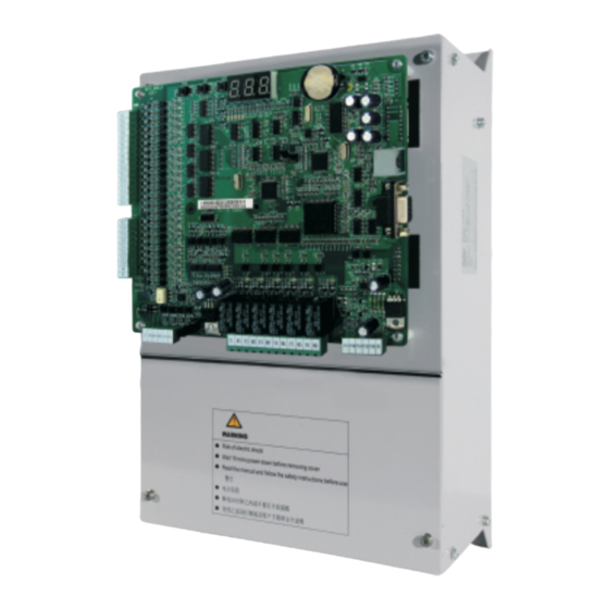
-
Contents
-
Table of Contents
-
Troubleshooting
-
Bookmarks
Quick Links
Related Manuals for Monarch NICE3000
Summary of Contents for Monarch NICE3000
-
Page 2: Table Of Contents
3.2 Use of the LED Operation Panel ………………18 3.3 CTB Board ……………………20 3.4 Display Board (MCTC-HCB)……………….22 3.5 CCB Board ……………………29 Chapter 4 Use of the NICE3000 …………….32 4.1 Wiring Diagrams Under Default Parameter Settings …………32 4.2 Description of Shaft Signals ……………….33 4.3 Typical Commissioning ………………..35 Chapter 5 Function Code Table …………….
-
Page 4
Overview… -
Page 5: Chapter 1 Overview
Brief NICE3000 Instruction Manual Chapter 1 Overview To facilitate the users who use the NICE3000 control system for the first time to understand how to commission the control system as quickly as possible, this manual briefly describes the specifications, wiring, common parameter setting, and common commissioning of the NICE3000.
-
Page 6
Product Information… -
Page 7: Chapter 2 Product Information
2.2 Mounting Dimensions The NICE3000 controller has three sizes: SIZE-C, SIZE-D, and SIZE-E, as shown in the following figure. SIZE-F is a customized model with different appearances but the same installation mode. The following figure and table show the appearance and physical dimensions of the NICE3000 controller.
-
Page 8
45 kW Note 1. The NICE3000 controller of other power ratings, such as above 45 kW is rarely applied in the elevator, and therefore, specifications are not provided here. For future detail on the options and availability, please contact Monarch. -
Page 9: Electrical Specifications
Product Information Brief NICE3000 Instruction Manual 2.3 Electrical Specifications Table 2-2 NICE3000 models and electrical specifications Power Input Current Output Motor Power System Model Capacity (kVA) Current (A) (kW) AC supply voltage: single-phase 220 V, range: –15% to 20% NICE-L-A/B-2002 13.2…
-
Page 10
3. Select the proper controller output current based on the motor rated current. Ensure that the controller output current is equal to or greater than the motor rated current. Table 2-3 Technical specifications of the NICE3000 Item Specification… -
Page 11
Product Information Brief NICE3000 Instruction Manual Item Specification Providing 57 protections such as: • Power-on short circuit detection • Protection at power phase loss and output phase loss Fault protection • Over-current protection • Door machine fault protection • Encoder protection •… -
Page 12: Braking Resistor
Brief NICE3000 Instruction Manual Product Information 2.4 Braking Resistor The models of 30 kW or below have a built-in braking unit, and you only need to connect an external braking resistor between PB and + terminals. For models above 30 kW, you need to install a braking unit and a braking resistor externally.
-
Page 13: Terminal Descriptions
ER OK COPHOP MDBUS CN12 RJ45 MCTC-MCB The NICE3000 provides a keypad with three keys and three 7-segment LEDs for display, and five LED status indicators. The NICE3000 also supports the external LED operation panel. Table 2-6 Terminal description and specifications…
-
Page 14
Brief NICE3000 Instruction Manual Product Information Mark Code Terminal Name Function Description Normally-open (NO), maximum current Y1/M1 to Y6/ Relay output and voltage rating: 5A, 250 VAC. The functions are set in F5-26 to F5-31. 15V/PGM/ Encoder interface for Connecting the incremental encoder… -
Page 16
Component Description… -
Page 17: Chapter 3 Component Description
Component Description Brief NICE3000 Instruction Manual Chapter 3 Component Description 3.1 Onboard Keypad Description The onboard keypad consists of three 7-segment LEDs and three buttons. You can query information about the controller and enter simple commands on the keypad. The following figure shows the appearance of the keypad.
-
Page 18
Brief NICE3000 Instruction Manual Component Description The function code groups displayed on the keypad are described as follows: 1. F0: display of floor and running direction The F0 menu is displayed on the keypad by default upon power-on. The first 7-segment LED indicates the running direction, while the last two 7-segment LEDs indicate the current floor of the elevator. -
Page 19: Use Of The Led Operation Panel
0 automatically. 3.2 Use of the LED Operation Panel The LED operation panel is connected to the RJ45 interface of the NICE3000 controller by means of an 8-core flat cable. You can modify the function parameters, monitor the working status, and run or stop the NICE3000 controller by using the LED operation panel.
-
Page 20
Brief NICE3000 Instruction Manual Component Description Unit Indicators ■ indicates OFF, and indicates ON. Hz: unit of frequency A: unit of current V: unit of voltage RPM: unit of rotational speed %: percentage Keys on the Operation Panel ■ Table 3-1 Keys on the operation panel… -
Page 21: Ctb Board
3.3 CTB Board The car top board (MCTC-CTB) is the elevator car control board of the NICE3000 controller. It consists of eight DI terminals, one AI terminal, and nine relay output terminals. The CTB can communicate with the CCB and HCB. The following figure shows the structure and size of the CTB.
-
Page 22
Brief NICE3000 Instruction Manual Component Description Type Terminal Name Description 24 VDC power supply to the +24V/COM 24 V power supply (communication Modbus with the HCB) MOD+/MOD- Communication with the HCB communication CN6 (AI) Ai-M Load cell signal input 0–10 VDC… -
Page 23: Display Board (Mctc-Hcb)
floor and running direction for the hall. This board can also be used as car display board. Monarch provides many types of display boards. The following describes only a few common types. If you need other types, please contact Monarch.
-
Page 24
Brief NICE3000 Instruction Manual Component Description Figure 3-5 Appearance of HCB-H Figure 3-6 Size of HCB-H 22.9 mm 4.2 mm Φ MCTC-HCB-H DOWN 34.3 mm 56.0 mm 22.5 mm 70.0 mm — 23 -… -
Page 25
Component Description Brief NICE3000 Instruction Manual The following table describes the input and output terminals. Table 3-4 Input and output terminals of HCB-H Terminal Name Function Interface for the elevator locking switch and up arrival indicator Pins 2 and 3 are for switch input. Pin 1 and 4 are power supply for the up arrival indicator. -
Page 26
Brief NICE3000 Instruction Manual Component Description Figure 3-8 Size of HCB-R1 3.5 mm Φ 22.8 mm MCTC-HCB-R1 6.7 mm 56.0 mm UP DOWN ST XF 10 mm 70 mm The following table describes the input and output terminals. Table 3-5 Input and output terminals of HCB-R1… -
Page 27
Component Description Brief NICE3000 Instruction Manual 3.4.3 HCB-D2 (Ultrathin Segment LED Display Board) The following figures show the appearance and size of HCB-D2. Figure 3-9 Appearance of HCB-D2 Figure 3-10 Size of HCB-D2 3.5 mm Φ 49 mm 56.0 mm UP DOWN ST XF 70.0 mm… -
Page 28
Brief NICE3000 Instruction Manual Component Description The following table describes the input and output terminals. Table 3-6 Input and output terminals of HCB-D2 Terminal Name Function Interface for the up call button and indicator Pins 2 and 3 are for up call input. Pins 1 and 4 are power supply for the up call indicator. -
Page 29
Component Description Brief NICE3000 Instruction Manual Figure 3-12 Size of HCB-U1 3-5.5 mm 4.5 mm Φ 53.0 mm 60.0 mm 9.4 mm 79.2 mm 16.9 mm The following table describes the input and output terminals. Table 3-7 Input and output terminals of HCB-U1… -
Page 30: Ccb Board
Brief NICE3000 Instruction Manual Component Description 3.5 CCB Board The car call board (MCTC-CCB) is another interface between users and the control system. Each CCB comprises 24 inputs and 22 outputs, including 16 floor buttons and 8 functional signals. The CCB mainly collects button calls and outputs signals of the button call indicators.
-
Page 31
Component Description Brief NICE3000 Instruction Manual The following table describes the input and output terminals. Table 3-8 Input and output terminals of the CCB Interface Pins 2 and 3 Pins 1 and 4 Remarks Floor 1 button input Floor 1 display output… -
Page 32
Use of the NICE3000… -
Page 33: Chapter 4 Use Of The Nice3000
Chapter 4 Use of the NICE3000 4.1 Wiring Diagrams Under Default Parameter Settings 4.1.1 Electric Wiring of the NICE3000 The following figure shows the electric wiring diagram of the NICE3000. Figure 4-1 Electric wiring diagram of the NICE3000 24 V…
-
Page 34: Description Of Shaft Signals
Brief NICE3000 Instruction Manual Use of the NICE3000 Note The above wiring diagram shows the default I/O function setting of group F5. The braking resistor is connected to PB and +. 4.1.2 Recommended CTB Wiring and Parameter Setting The following wiring diagram shows the default function setting of the CTB. You can change the input polarity (NO/NC) of the CTB terminals in F5-25.
-
Page 35
4.2.3 Leveling Switch The NICE3000 system allows the use of 1 to 3 leveling switches. If only one leveling sensor is used, the corresponding function code which is used for input of leveling signal is allocated with function 03 (NO input of door zone signal). -
Page 36: Typical Commissioning
You need to add two re-leveling switches if applying the door pre-open function. In this case, you need to increase the length of the flag properly. For details on the door pre-open module, contact Monarch or local agent for more information. 4.3 Typical Commissioning 4.3.1 Check Before Commissioning…
-
Page 37
Use of the NICE3000 Brief NICE3000 Instruction Manual R, S, T, U, V, W Input and output terminals of the controller and power supply for switches Brake power coils and wiring terminals of the braking resistor Nodes of various control signals… -
Page 38
4.3.2 Commissioning at Inspection Speed To implement accurate control on the motor, motor auto-tuning must be performed before the use of the NICE3000. Ensure that the installation and wiring satisfy the safety requirements and technical specifications before the auto-tuning. No-load Auto-tuning ■… -
Page 39
Use of the NICE3000 Brief NICE3000 Instruction Manual Then, set F1-12 (Encoder lines per revolution) based on the encoder nameplate. Remove the load from the motor completely. Set F1-11 to 2 (No-load auto-tuning). «TUNE» is displayed on the operation panel. Release the brake manually and press on the operation panel. -
Page 40
Brief NICE3000 Instruction Manual Use of the NICE3000 • 0: SIN/COS encoder • 1: UVW encoder F1-12 (Encoder lines per revolution) If applying the Heidenhain ECN 1313 or 413 encoder with the MD32PG5 card, set F1- 00 to 0. Enter the motor nameplate parameters correctly. -
Page 41
Use of the NICE3000 Brief NICE3000 Instruction Manual To perform with-load auto-tuning for asynchronous motor, do as follows: Set F0-01 (Command source selection) to 0 (Operation panel control) and press STOP on the operation panel to reset the current faults. -
Page 42
Brief NICE3000 Instruction Manual Use of the NICE3000 To perform with-load auto-tuning for PMSM, do as follows: Check the motor power cables and encoder wiring. Ensure that the motor’s UVW power cables are connected to the controller’s UVW terminals properly, and the encoder’s AB, UVW or CDZ signal cables are connected to the AB, UVW or CDZ terminals of the PG card properly. -
Page 43
Use of the NICE3000 Brief NICE3000 Instruction Manual Note After the motor auto-tuning is complete, the system prohibits inspection running for 8s and saves parameters during the time. 4.3.3 Summary of Commissioning at Inspection Speed Asynchronous Motor Auto-tuning Process ■… -
Page 44
Brief NICE3000 Instruction Manual Use of the NICE3000 PMSM Auto-tuning Process ■ Figure 4-4 Auto-tuning process of the PMSM Set F0-01 to 1 to restore Set F0-01 to 0 (No-load tuning ) distance control . or 1 (With-load tuning ) Resume the rope . -
Page 45
(F0-00 = 1, F0-01 = 1). 4. The top floor number (F6-00) and bottom floor number (F6-01) are set correctly. 5. The NICE3000 system is not in the fault alarm state. If there is a fault at the moment, STOP press to reset the fault. -
Page 46
Brief NICE3000 Instruction Manual Use of the NICE3000 For a faster system response, increase the proportional gain and reduce the integral gain. Be aware that a fast system response causes system oscillation. Figure 4-5 Relationship between switchover frequencies PI regulation… -
Page 47
Use of the NICE3000 Brief NICE3000 Instruction Manual Function Parameter Setting Range Default Description Code Name It specifies the time required from when the system outputs the open signal to when the Brake release 0.200s F3-19 0.000–1.000s brake is completely released. -
Page 48
Brief NICE3000 Instruction Manual Use of the NICE3000 Function Parameter Name Setting Range Default Code 0: Pre-torque invalid 1: Load cell pre-torque F8-01 Pre-torque selection compensation 2: Automatic pre-torque compensation Pre-torque offset 0.0%–100.0% 50.0% F8-02 Zero servo current coefficient 0.20%–50.0% 15.0%… -
Page 49
Use of the NICE3000 Brief NICE3000 Instruction Manual Mechanical Construction ■ The mechanical construction affecting the riding comfort involves the guide rail, guide shoe, steel rope, installation of the brake, balance of the car and the resonance caused by the car, guild rail and motor. -
Page 50
Figure 4-7 Monitoring the door open and close limit signals 4.3.7 Password Setting The NICE3000 controller provides the parameter password protection function. Here gives an example of changing the password into 12345, as shown in the following figure. Figure 4-8 Example of changing the password… -
Page 51
Use of the NICE3000 Brief NICE3000 Instruction Manual In the password protection unlocked status, you can change the password at any time. The last input number will be the user password. If you want to disable the password protection function, enter the correct password and then set FP-00 to 0. -
Page 52
Function Code Table… -
Page 53: Chapter 5 Function Code Table
Function Code Table Brief NICE3000 Instruction Manual Chapter 5 Function Code Table Function Parameter Name Setting Range Default Code Group F0: Basic parameters 0: Sensorless flux vector control F0-00 Control mode (SFVC) 1:Closed-loop vector control (CLVC) 0: Operation panel control…
-
Page 54
Brief NICE3000 Instruction Manual Function Code Table Function Parameter Name Setting Range Default Code 0: No operation 1: With-load auto-tuning F1-11 Auto-tuning mode selection 2: No-load auto-tuning 3: Shaft auto-tuning F1-12 Encoder lines per revolution 0–10000 1024 F1-13 Encoder fault detection time 0.0–10.0s… -
Page 55
Function Code Table Brief NICE3000 Instruction Manual Function Parameter Name Setting Range Default Code F3-13 Position of down slow-down 1 0.00–300.00 m 0.00 m F3-14 Position of up slow-down 2 0.00–300.00 m 0.00 m F3-15 Position of down slow-down 2 0.00–300.00 m… -
Page 56
Brief NICE3000 Instruction Manual Function Code Table Function Parameter Name Setting Range Default Code F5-01 X1 function selection NO input: 01–31 00: No function F5-02 X2 function selection 01: Up leveling signal F5-03 X3 function selection 02: Down leveling signal… -
Page 57
Function Code Table Brief NICE3000 Instruction Manual Function Parameter Name Setting Range Default Code F5-13 X13 function selection NC input: 33–63 33: Up leveling signal F5-14 X14 function selection 34: Down leveling signal F5-15 X15 function selection 35: Door zone signal… -
Page 58
Brief NICE3000 Instruction Manual Function Code Table Function Parameter Name Setting Range Default Code F5-25 CTB input type selection 0–255 The NO/NC setting of terminals X1 to X8 on the CTB is listed in the following table. Terminal Parameter Name… -
Page 59
Function Code Table Brief NICE3000 Instruction Manual Function Parameter Name Setting Range Default Code F5-32 Communication status display Figure 5-1 Communication status display CANbus Modbus for hall call at each floor The upmost left 7-segment LED is expressed by 0–9, and used for CAN communication monitoring. -
Page 60
Brief NICE3000 Instruction Manual Function Code Table Function Parameter Name Setting Range Default Code F5-34 F5-35 Segment Indication Segment Indication Light curtain 1 Up leveling signal Light curtain 2 Down leveling signal Door 1 open limit Door zone signal Door 2 open limit… -
Page 61
Function Code Table Brief NICE3000 Instruction Manual Function Parameter Name Setting Range Default Code Door machine 1 light curtain Door open button display Door machine 2 light curtain Door close button display Door open delay button Brake feedback 2 display… -
Page 62
Brief NICE3000 Instruction Manual Function Code Table Function Parameter Name Setting Range Default Code • Bit0: Dispersed waiting • Bit1: Reserved • Bit2: Parallel implemented at monitoring port • Bit4: Door not open at power-on if F6-09 Parallel selection elevator-locked signal is enabled •… -
Page 63
Function Code Table Brief NICE3000 Instruction Manual Function Parameter Name Setting Range Default Code Time-based floor service 2 F6-22 00.00–23.59 (hour.minute) 00.00 start time Time-based floor service 2 end F6-23 00.00–23.59 (hour.minute) 00.00 time Floor 1 of time-based floor F6-24 0–65535 (floors 1–16) -
Page 64
Brief NICE3000 Instruction Manual Function Code Table Function Parameter Name Setting Range Default Code F8-05 Current car load 0–1023 F8-06 Car no-load load 0–1023 F8-07 Car full-load load 0–1023 0: Disabled F8-08 Anti-nuisance function 1: Enabled (load cell sensor required) -
Page 65
Function Code Table Brief NICE3000 Instruction Manual Function Parameter Name Setting Range Default Code Group FB: Door function parameters FB-00 Number of door machine (s) 1–2 FB-01 CTB software 0–99 Service floor 1 of door machine FB-02 0–65535 (floors 1–16) 65535 Service floor 2 of door machine… -
Page 66
Brief NICE3000 Instruction Manual Function Code Table Function Parameter Name Setting Range Default Code FC-02 Over-load protection coefficient 0.50–10.00 1.00 FC-03 Over-load alarm coefficient 50–100% FC-04 Opposite door selection 1–10 The first two digits indicate the floor and the last two digits indicate the fault code. -
Page 67
Function Code Table Brief NICE3000 Instruction Manual Function Parameter Name Setting Range Default Code FC-31 Latest fault time (hour/minute) 00.00–23.59 00.00 Group FD: Communication parameters 0–5: 9600 bps FD-00 Baud rate setting 6: 19200 bps 7: 38400 bps 0: No check-out, data format <8,N,2>… -
Page 68
Brief NICE3000 Instruction Manual Overiew Function Parameter Name Setting Range Default Code FE-08 Floor 8 corresponding display 06: display 6 1908 07: display 7 FE-09 Floor 9 corresponding display 1909 08: display 8 FE-10 Floor 10 corresponding display 0100 09: display 9… -
Page 69
Overview Brief NICE3000 Instruction Manual Function Parameter Name Setting Range Default Code • Bit0: Attendant function • Bit1: Returning to base floor at fire emergency • Bit2: Re-leveling function • Bit3: Pre-open function • Bit4: Removal of stuck hall calls •… -
Page 70
Function Parameter Name Setting Range Default Code • Bit1: Door open holding at door open limit • Bit2: Not output door close signal at door close limit • Bit3: Detecting door close limit in inspection mode • Bit4: Auto reset for running and brake contactor stuck •… -
Page 72
System Application… -
Page 73: Chapter 6 System Application
6.1 Parallel Mode and Group Mode 6.1.1 Parameter Setting The NICE3000 has the parallel control function. Two NICE3000 controllers can exchange the elevator information by means of CAN or RS485 communication, coordinating response of the two elevators to hall calls and improving the elevator efficiency.
-
Page 74
Brief NICE3000 Instruction Manual System Application Figure 6-1 Parallel connection by means of CAN communication Elevator Elevator PRG UP SET PRG UP SET CAN communication port CAN communication port connecting CTB of elevator 1# connecting CTB of elevator 2# UP button… -
Page 75
Figure 6-2 Parallel connection at the monitoring port 6.1.4 Setting of Physical Floors Physical floors, relative to the NICE3000 control system, are defined by the installation position of the leveling flag. The floor (such as the ground floor) at which the lowest leveling flag is installed corresponds to physical floor 1. -
Page 76: Emergency Evacuation At Power Failure
Uninterrupted power supply (UPS) • Shorting PMSM stator Here we first introduce the implementation through the NICE3000’s shorting PMSM stator scheme, which can save energy and improve safety. 6.2.1 Shorting PMSM Stator Shorting PMSM stator means shorting phases UVW of the PMSM, which produces resistance to restrict movement of the elevator car.
-
Page 77
System Application Brief NICE3000 Instruction Manual Figure 6-3 Wiring of the independent shorting PMSM stator contactor Safety circuit SW: RUN contactor 110 VAC FX: shorting PMSM stator contactor 24 V NICE3000 Motor Then set the related parameters as follows: Table 6-3 Parameter setting under the shorting PMSM stator scheme… -
Page 78
Brief NICE3000 Instruction Manual System Application The following figure shows various contacts of the contactors. Figure 6-5 Various contacts of the contactors Phase Safety sequence relay contactor 110 V Safety circuit Emergency 24 V feedback 62 72 53 61 5 13 71 81 The UPS power is recommended in the following table. -
Page 79: Opposite Door Control
System Application Brief NICE3000 Instruction Manual 6.3 Opposite Door Control Set related parameters according to the following table. Table 6-6 Parameter setting for opposite door control Opposite Door Parameter Setting Function Description Control Mode FE-33 BIT15 = 0: The hall call buttons of both door sides are connected…
-
Page 80
Brief NICE3000 Instruction Manual System Application Opposite Door Parameter Setting Function Description Control Mode This control mode applies to double call boards, double operation panels and two CCBs connected in serial. The hall call DIP switch address of the front door is set based on floor (1-15). -
Page 82
Troubleshooting… -
Page 83: Chapter 7 Troubleshooting
Chapter 7 Troubleshooting 7.1 Description of Fault Levels The NICE3000 has more than 60 pieces of alarm information and protective functions. It monitors various input signals, running conditions and feedback signals. If a fault occurs, the relevant protective function acts and the system displays the fault code.
-
Page 84: Fault Information And Troubleshooting
Brief NICE3000 Instruction Manual Troubleshooting 7.2 Fault Information and Troubleshooting If an alarm is reported, the system performs corresponding processing based on the fault level. You can handle the fault according to the possible causes described in the following table.
-
Page 85
Troubleshooting Brief NICE3000 Instruction Manual Fault Name Possible Causes Solution Level Code 8. Check whether the balance coefficient is correct. 9. Check whether the encoder wirings are correct. For asynchronous motor, perform SFVC and compare the current to judge whether the encoder works properly. -
Page 86
Brief NICE3000 Instruction Manual Troubleshooting Fault Name Possible Causes Solution Level Code 1. The input voltage is too high. 2. The braking Over-voltage resistance is too during large, or the braking 4. Check whether the cable deceleration unit fails. connecting the braking resistor 3. -
Page 87
Troubleshooting Brief NICE3000 Instruction Manual Fault Name Possible Causes Solution Level Code 1. The output wiring 1. Check the wiring. of the main circuit is Power output 2. Check whether the contactor loose. phase loss at the output side is normal. -
Page 88
Brief NICE3000 Instruction Manual Troubleshooting Fault Name Possible Causes Solution Level Code 1. Check whether F1-00 is set 1. Check whether correctly. the encoder model 2. Check the encoder wiring. matches the motor. 3. Check whether the encoder 2. The encoder wiring is normal. -
Page 89
The CPU is CPU abnormal right two pins of J9 are shorted. abnormal. 2. Contact the agent or Monarch to replace the control board. 1. The feedback speed is 1.15 times of the maximum 1. Check whether the encoder running speed. -
Page 90
Brief NICE3000 Instruction Manual Troubleshooting Fault Name Possible Causes Solution Level Code 1. Upon power-on, E35 is reported when the flag height is detected to be 0 or the RUN contactor is detected to keep open. • Check whether the down slow-down switch is valid. -
Page 91
Troubleshooting Brief NICE3000 Instruction Manual Fault Name Possible Causes Solution Level Code 1. The RUN contactor feedback is valid 1. Check whether the feedback when the elevator contact of the contactor acts starts up. properly. 2. The feedback 2. Check whether the feedback… -
Page 92
Brief NICE3000 Instruction Manual Troubleshooting Fault Name Possible Causes Solution Level Code 1. Check the status of the safety circuit switches. 2. Check whether the external power supply is normal. Safety circuit The safety circuit 3. Check whether the safety breaking signal breaks off. -
Page 93
1. Check the communication cable connection. Feedback from the communication 2. Check whether the 24 V CTB is abnormal. abnormal power supply of the NICE3000 is normal. 1. Check the communication cable connection. 2. Check whether the 24 V Feedback from the communication power supply of the NICE3000 HCB is abnormal. -
Page 94
Brief NICE3000 Instruction Manual Troubleshooting Fault Name Possible Causes Solution Level Code The door does not open to the limit Stop at another Check the door open limit at the current floor landing floor signal. when the elevator runs automatically. -
Page 95
Troubleshooting Brief NICE3000 Instruction Manual — 94 -… -
Page 96
The Product Warranty Card is not re-issued. Please keep the card and present it to the maintenance personnel when asking for maintenance. If there is any problem during the service, contact Monarch’s agent or Monarch directly. This agreement shall be interpreted by Suzhou MONARCH Control Technology Co., Ltd. -
Page 97
Product Warranty Card Add. of unit: Name of unit: Contact person: Customer information P.C.: Tel.: Product model: Body barcode (Attach here): Product information Name of agent: (Maintenance time and content): Failure information Maintenance personnel:…