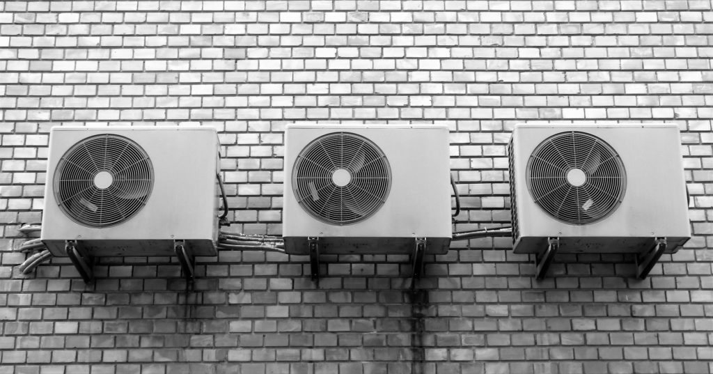
Система кондиционирования воздуха в домах и квартирах уже давно стала привычным явлением. В летнюю жару приятно возвращаться домой, где благодаря сплит системе LG создана комфортная температура. Кондиционеры LG по праву занимают одни из лидирующих позиций во всем мире, предлагая своим покупателям передовые разработки в области технологий и изысканный дизайн. Компания производит множество моделей: от оконных кондиционеров до современных сплит систем. И, несмотря на то, что сплит системы LG являются одними из самых надежных на рынке, все-таки иногда возможны ситуации, когда кондиционер LG выходит из строя. В этом случае на дисплее кондиционера LG высвечиваются определенные коды ошибок. С их помощью можно понять, какая система кондиционера LG вышла из строя, и попытаться или устранить возникшую поломку самостоятельно, или, что правильнее, обратиться в сервисный центр LG.
Давайте рассмотрим коды ошибок кондиционеров LG:
- Ошибка кондиционеров LG CH 01 означает, что во внутреннем датчике температуры воздуха произошло короткое замыкание или обрыв цепи.
- Ошибка сплит системы LG CH 02 означает, что замкнуло датчик температуры испарителя или произошел обрыв в цепи.
- Ошибка сплит системы LG CH 03 означает, что кондиционер и нагревает, и охлаждает воздух в помещении одновременно.
- Ошибка сплит системы LG CH 04 показывает, что в температурном датчике конденсатора произошло короткое замыкание или обрыв цепи.
- CH 05 ошибка показывает, что нарушено соединение между внутренним и внешним блоком кондиционера. 05 ошибка возникает из-за обрыва линии или отсутствия контакта.
- Ошибка сплит системы LG CH 06 показывает, что превышен максимальный предел электропитания в цепи инверторного модуля.
- Ошибка сплит системы LG CH 07 показывает, что превышен максимальный предел электропитания компрессора.
- CH 08 ошибка показывает, что не вращается вентилятор внутреннего блока.
- Ошибка сплит системы LG СН 09 означает, что не вращается вентилятор внешнего блока.
- Ошибка сплит системы LG CH 10 кондиционера LG означает, что неисправен терморезистор контроля температуры корпуса компрессора сплит системы LG.
Все перечисленные коды ошибок LG кондиционера достаточно серьезны и за устранением причин возникших неполадок лучше обратиться к специалистам сервисного центра LG.
Если кода ошибки нет, а мигает один или все светодиодные индикаторы на панели советуем посмотреть в инструкции полную версию кодов ошибок кондиционера LG, чтобы уточнить причину.
Если на панели кондиционера мигает код Po, это означает, что система находится в энергосберегающем режиме, ошибки LG кондиционера в данном случае нет. Также об отсутствии ошибки LG кондиционера говорит тот факт, что на панели мигает код Lo, что означает, что система находится в режиме тестирования.
Варианты ошибок, которые отображаются на панели, различаются в зависимости от модели кондиционера, и все они требуют вашего пристального внимания и решения с привлечением профессионалов или своими силами. Так техника прослужит вам нет 1 год и не 5 лет, а гораздо дольше.
Дополнительный совет: регулярно мойте фильтры в кондиционерах. Во время работы кондиционер прогоняет через себя воздух, в котором содержится пыль, волосы или шерсть, если у вас есть домашний питомец. Все это оседает на фильтрах и внутренних частях прибора и кроме собственно загрязнения может послужить причиной прочих проблем:
- Из-за пыли воздух в кондиционере хуже циркулирует, и тем самым помещение медленнее охлаждается.
- Перегревается теплообменник, что может привести к быстрому износу компрессора.
- В пыли могут появляться вирусы, споры плесени и грибков, пылевые клещи, что может стать причиной аллергии и других проблем со здоровьем.
Обычно помыть фильтр бывает достаточно просто. Например, в случае с моделью LG DualCool решетка фильтра располагается по всей верхней поверхности, ее легко снимать и вставлять на место. Если модель вашего кондиционера LG устроена иначе — обратитесь в фирменный сервис LG, чтобы фильтры прочистил квалифицированный сотрудник. Это в любом случае доставит меньше неудобств, некомфортная температура дома или риски для здоровья.
00 Text the 1, 2 or 3 digit fault code number only. I.e. If you see fault code CH07 on your indoor unit or R/Controller, only type 7 or 07 in your text message. 01 Indoor unit return air sensor fault. Disconnect sensor from PCB and measure resistance. 8 kOhm at 30C and 13 kOhm at 20C if not replace sensor 1 Indoor unit return air sensor fault. Disconnect sensor from PCB and measure resistance. 8 kOhm at 30C and 13 kOhm at 20C if not replace sensor 02 Indoor Pipe Sensor or Outdoor Sensor Assy fault, Open or Short. Disconnect from PCB and measure resistance. Air sensor = 10 kOhm at 25C, Pipe sensor = 5 kOhm at 25C. If not replace sensor. 2 Indoor Pipe Sensor or Outdoor Sensor Assy fault, Open or Short. Disconnect from PCB and measure resistance. Air sensor = 10 kOhm at 25C, Pipe sensor = 5 kOhm at 25C. If not replace sensor. 03 Remote controller comms error. Check wired correctly, if so check dipswitch in RC. Set to Sg for 1 unit, or Gr for group then reset power 3 Remote controller comms error. Check wired correctly, if so check dipswitch in RC. Set to Sg for 1 unit, or Gr for group then reset power 04 RAC Product = Heat Sink Sensor Error, Open/Short Cct or over 95C. Commercial Product = Condensate pump float switch risen. Check drain pan is empty, check pump is working OK. If no pump check blue jumper plug is inserted in socket CN Float. 4 RAC Product = Heat Sink Sensor Error, Open/Short Cct or over 95C. Commercial Product = Condensate pump float switch risen. Check drain pan is empty, check pump is working OK. If no pump check blue jumper plug is inserted in socket CN Float. 05 Comms Error, check your wiring, remove external pumps. Split/Multi — check volts from terminal N to 3 = 0 — 65 Vdc, Multi V — 4 Vdc terminals 3 and 4 5 Comms Error, check your wiring, remove external pumps. Split/Multi — check volts from terminal N to 3 = 0 — 65 Vdc, Multi V — 4 Vdc terminals 3 and 4 06 Indoor unit coil sensor fault. Disconnect from PCB measure resistance. 10 kOhm at 10C and 4 kOhm at 30C. if not replace sensor. Split = text 21 6 Indoor unit coil sensor fault. Disconnect from PCB measure resistance. 10 kOhm at 10C and 4 kOhm at 30C. if not replace sensor. Split = text 21 07 Multi Splits and Multi V = indoor unit is set to run in a different mode from the master indoor unit. Set ALL indoor units to cooling or ALL to heating to clear. Splits = Compressor Over Current (CT2), also see Code 06. 7 Multi Splits and Multi V = indoor unit is set to run in a different mode from the master indoor unit. Set ALL indoor units to cooling or ALL to heating to clear. Splits = Compressor Over Current (CT2), also see Code 06. RAC Indoor unit BLDC Fan problem. This is caused by the Indoor fan being locked. Check fan motor is plugged in correctly, Electrically & Mechanically sound. 08 Check the fan motor turns freely, check the AC Voltage supplied to the fan motor, this will vary from 120 V ac at low speed to 170V AC at high speed. If no Voltage is present the the PCB is faulty, if Voltage is present the fan motor will be Faulty. RAC Indoor unit BLDC Fan problem. This is caused by the Indoor fan being locked. Check fan motor is plugged in correctly, Electrically & Mechanically sound. 8 Check the fan motor turns freely, check the AC Voltage supplied to the fan motor, this will vary from 120 V ac at low speed to 170V AC at high speed. If no Voltage is present the the PCB is faulty, if Voltage is present the fan motor will be Faulty. 09 Split = Outdoor unit fan problem. Check Outdoor fan motor is plugged in, Electrically & Mechanically sound, if not replace motor, otherwise replace PCB. Multi V = Indoor unit EEPROM error — Replace the indoor unit PCB, and then make sure to do Auto addressing and input the address of central control. 9 Split = Outdoor unit fan problem. Check Outdoor fan motor is plugged in, Electrically & Mechanically sound, if not replace motor, otherwise replace PCB. Multi V = Indoor unit EEPROM error — Replace the indoor unit PCB, and then make sure to do Auto addressing and input the address of central control. 10 RAC Product: Compressor discharge sensor fault. Disconnect from PCB measure resistance 237 kOhm at 20°C, 168 kOhm at 30C. Multi Fdx & Multi V text 8 11 Multi V indoor unit not connected to an outdoor unit. Check comms wiring is correct, and check initialisation has been carried out correctly 12 RAC Product = EEPROM Sum Check Error, text 60 for help. 13 RAC Product = PSC (Reactor) Error, text 27 for help. 14 RAC Product = Compressor Phase Current Error 15 no such fault code Text 1, 2 or 3 digit fault code number only. If you see fault code CH07 only type 7 in your text message 16 no such fault code Text 1, 2 or 3 digit fault code number only. If you see fault code CH07 only type 7 in your text message 17 no such fault code Text 1, 2 or 3 digit fault code number only. If you see fault code CH07 only type 7 in your text message 18 no such fault code Text 1, 2 or 3 digit fault code number only. If you see fault code CH07 only type 7 in your text message 19 no such fault code Text 1, 2 or 3 digit fault code number only. If you see fault code CH07 only type 7 in your text message 20 no such fault code Text 1, 2 or 3 digit fault code number only. If you see fault code CH07 only type 7 in your text message 21 Inverter compressor run current high. Check compressor windings all equal 1 to 4 Ohms, Check to earth 50 MOhm minimum, check run current 22 Inverter compressor run current high. Check compressor windings all equal 1 to 4 Ohms . Check to earth 50 MOhm minimum, check run current 23 Inverter dc voltage low. Check dc voltage of capacitors 300 Vdc for 1Ph and 600 Vdc for 3Ph. If OK change outdoor inverter PCB 24 Splits and Multi Splits = High or low pressure trip. Low at 1 bar High at 35 bar check pressures. Multi V = High pressure trip. 25 Check power supply voltage to the outdoor unit is correct (1ph ?220 Vac ±10% or 3ph ?380 Vac ±10%). If OK, check fuses, if fuses are OK replace outdoor main PCB 26 Inverter compressor seized. Check compressor windings all equal resistance 1 to 4 Ohms, check to earth 50 MOhm minimum, check run current and Inverter outputs 27 Inverter current irregularity. Check inverter PCB, check reactor connections and its resistance is less than 1 ohm. 28 Inverter dc voltage too high. Check dc voltage of capacitors 300 Vdc for 1Ph and 600 Vdc for 3Ph. If OK change outdoor inverter PCB 29 no such fault code Text 1, 2 or 3 digit fault code number only. If you see fault code CH07 only type 7 in your text message 30 no such fault code Text 1, 2 or 3 digit fault code number only. If you see fault code CH07 only type 7 in your text message 31 no such fault code Text 1, 2 or 3 digit fault code number only. If you see fault code CH07 only type 7 in your text message 32 Inverter compressor discharge temperature too high. If over 105°C, check refrigerant charge 33 Excessive rise of standard compressor discharge temperature. If over 105°C check refrigerant charge 34 Excessive high pressure rise, over 35 bar at HP sensor. Check pressures, check coils, and filters are clean check for OFN in system pipework 35 Excessive low pressure drop under 1 Bar at LP sensor. Check pressures, and check service valves open 36 no such fault code Text 1, 2 or 3 digit fault code number only. If you see fault code CH07 only type 7 in your text message 37 no such fault code Text 1, 2 or 3 digit fault code number only. If you see fault code CH07 only type 7 in your text message 38 no such fault code Text 1, 2 or 3 digit fault code number only. If you see fault code CH07 only type 7 in your text message 39 no such fault code Text 1, 2 or 3 digit fault code number only. If you see fault code CH07 only type 7 in your text message 40 Inverter ac current abnormal. Check compressor windings all equal resistance 1 to 4 Ohms, check to earth 50 MOhm minimum, check run current and inverter outputs 41 Inverter compressor discharge sensor fault. Disconnect from PCB measure resistance 237 kOhm at 20°C and 168 kOhm at 30°C. 42 Low pressure sensor fault. Check dc voltage between white and black cable on plug. Multi V: 1 Vdc = 4 bar up to 5 Vdc = 32 bar 43 High pressure sensor fault. Check dc voltage between white and black cable on plug. Multi V: 1 Vdc = 8 bar up to 2.5 Vdc = 37 bar 44 Outdoor unit air sensor fault. Disconnect from PCB and measure resistance. 8 kOhm at 30C and 13 kOhm at 20C. If OK replace PCB, if not replace sensor 45 Outdoor unit coil sensor fault. Disconnect from PCB measure resistance. 10 kOhm at 10°C and 4 kOhm at 30°C. If OK replace PCB, if not replace sensor 46 Outdoor unit suction sensor fault. Disconnect from PCB and measure resistance. 10 kOhm at 10°C and 4 kOhm at 30°C. If OK replace PCB, if not replace sensor 47 Compressor discharge sensor fault. Disconnect from PCB measure resistance. 237 kOhm at 20°C and 168 kOhm at 30°C. If OK replace PCB, if not replace sensor 48 Split/Multi Split = Outdoor unit discharge and air sensor both unplugged. Multi V = Outdoor unit coil sensor. Text 45 for diagnostics 49 Check power supply voltage to the outdoor unit is correct (1ph ?220 Vac ±10% or 3ph ?380 Vac ±10%). If OK check fuses, if fuses OK, replace outdoor main PCB 50 no such fault code Text 1, 2 or 3 digit fault code number only. If you see fault code CH07 only type 7 in your text message 51 Unit mismatch. Check model number of units do not exceed maximum. Multi V — also check Sub outdoor unit dipswitch settings 52 Communication error between inverter PCB and main outdoor unit PCB. Check wiring fuses and LEDs . If OK either inverter or main PCB defective 53 Comms error indoor to outdoor unit. Check your wiring . Split and Multi — check voltage from terminal N to 3 = 0 — 65 Vdc, Multi V — 4 Vdc terminals 3 and 4 54 Reverse or open phase. Check all 3 phases are present and correct. If correct voltage appears at all three phases, swap any two to cure the fault 55 no such fault code Text 1, 2 or 3 digit fault code number only. If you see fault code CH07 only type 7 in your text message 56 no such fault code Text 1, 2 or 3 digit fault code number only. If you see fault code CH07 only type 7 in your text message 57 Comms error between outdoor main PCB and inverter PCB. Check wiring fuses and LEDs are lit. If OK either inverter or main PCB defective 58 no such fault code Text 1, 2 or 3 digit fault code number only. If you see fault code CH07 only type 7 in your text message 59 no such fault code Text 1, 2 or 3 digit fault code number only. If you see fault code CH07 only type 7 in your text message 60 Outdoor unit PCB EEPROM failure, try removing EEPROM and refitting if removable (possible contact fault), otherwise replace PCB if the EEPROM is non-removable. 61 Condenser coil over 65°C. Check coil and filters are clean and free from debris, and airflow is OK. Check system pressures for non-condesables 62 Inverter over 85°C. Check air flow across heat sink, check inverter tight to heatsink use thermal paste. Multi V — check inverter cooling fan 63 Multi F(DX) — «Cond. Pipe Sensor Temp. Low» (opposite to Error Code 61). Check Temperature/Resistance reading and replace sensor if found to be faulty. If sensor okay, check for cause of low temperature and rectify. 64 no such fault code Text 1, 2 or 3 digit fault code number only. If you see fault code CH07 only type 7 in your text message 65 Outdoor unit inverter fin temperature sensor fault. Disconnect from PCB measure resistance. 8 kOhm at 30°C and 13 kOhm at 20°C 67 Outdoor Fan Motor siezed, or rotation sensing circuit failure. Check motor for mechanical and/or electrical failure, if okay replace pcb. 100 Excessive discharge temperature rise 105°C Sub condenser 1 standard compressor. Check refrigerant 101 Excessive discharge temperature rise 105°C Sub condenser 1 standard compressor. Check refrigerant 102 Excessive discharge temperature rise 105°C Sub condenser 2 standard compressor. Check refrigerant 103 Excessive discharge temperature rise 105°C Sub condenser 2 standard compressor. Check refrigerant 104 Communication error between Main and Sub outdoor units. Check comms wiring and power to all outdoor units 105 Communication error between outdoor main PCB and fan PCB. Check plug connections and LEDs. If OK, replace either main or fan PCB 106 Outdoor unit fan motor high current. Check fans rotate freely, and are connected correctly 107 Outdoor unit low voltage to fan PCB. Check 300 Vdc supply, check fuses and plug connections. If OK, replace fan PCB 108 Communication error between outdoor main PCB, and fan PCB. Check plug connections and LEDs. If OK replace either main or fan PCB 109 Sub 1 excessive rise of high pressure. Check pressures, check for non condensables, check heat exchanger coil is free from debris 110 Sub 1 reverse or open phase. Check all 3 phases are present and correct. If correct voltage appears at all three phases, swap any two to cure the fault 111 Communication error between Main and Sub outdoor units. Check comms wiring and power to all outdoor units 113 Main outdoor unit liquid pipe sensor fault. Disconnect from PCB and measure resistance. 10 kOhm at 10°C and 4 kOhm at 30°C 114 Main outdoor unit Subcool inlet sensor fault. Disconnect from PCB and measure resistance. 10 kOhm at 10°C and 4 kOhm at 30°C 115 Main outdoor unit Subcool outlet sensor fault. Disconnect from PCB and measure resistance. 10 kOhm at 10°C and 4 kOhm at 30°C 116 Sub 1 high pressure sensor fault. Check dc voltage between white and black cable on plug. Multi V: 1 Vdc = 8 bar up to 2.5 Vdc = 37 bar 117 Sub 1 low pressure sensor fault. Check dc voltage between white and black cable on plug. Multi V: 1 Vdc = 4 bar up to 5 Vdc = 32 bar 118 Sub 1 outdoor unit air sensor fault. Disconnect from PCB and measure resistance. 8 kOhm at 30°C and 13 kOhm at 20°C. If OK replace PCB, if not replace sensor 120 Sub 1 outdoor unit suction sensor fault. Disconnect from PCB and measure resistance. 10 kOhm at 10°C and 4 kOhm at 30°C. if not replace sensor 121 Sub 1 compressor 1 discharge sensor fault. Disconnect from PCB measure resistance 237 kOhm at 20°C and 168 kOhm at 30°C. if not replace sensor 122 Sub 1 compressor 2 discharge sensor fault. Disconnect from PCB measure resistance 237 kOhm at 20°C and 168 kOhm at 30°C. if not replace sensor 123 Sub 1 outdoor unit coil sensor A fault. Disconnect from PCB measure resistance. 10 kOhm at 10°C and 4 kOhm at 30°C. If OK replace PCB, if not replace sensor 124 Sub 1 outdoor unit coil sensor B fault. Disconnect from PCB measure resistance. 10 kOhm at 10°C and 4 kOhm at 30°C. If OK replace PCB, if not replace sensor 125 Sub 1 outdoor unit liquid pipe sensor fault. Disconnect from PCB and measure resistance. 10 kOhm at 10°C and 4 kOhm at 30°C 126 Sub 1 outdoor unit Subcool inlet sensor fault. Disconnect from PCB and measure resistance. 10 kOhm at 10°C and 4 kOhm at 30°C 127 Sub 1 outdoor unit Subcool outlet sensor fault. Disconnect from PCB and measure resistance. 10 kOhm at 10°C and 4 kOhm at 30°C 128 Sub 2 high pressure sensor fault. Check dc voltage between white and black cable on plug. Multi V: 1 Vdc = 8 bar up to 2.5 Vdc = 37 bar 129 Sub 2 low pressure sensor fault. Check dc voltage between white and black cable on plug. Multi V: 1 Vdc = 4 bar up to 5 Vdc = 32 bar 130 Sub 2 outdoor unit air sensor fault. Disconnect from PCB and measure resistance. 8 kOhm at 30°C and 13 kOhm at 20°C. If OK replace PCB, if not replace sensor 132 Sub 2 outdoor unit suction sensor fault. Disconnect from PCB and measure resistance. 10 kOhm at 10°C and 4 kOhm at 30°C.if not replace sensor 133 Sub 2 compressor 1 discharge sensor fault. Disconnect from PCB measure resistance 237 kOhm at 20°C and 168kOhm at 30°C. if not replace sensor 134 Sub 2 compressor 2 discharge sensor fault. Disconnect from PCB measure resistance 237 kOhm at 20°C and 168kOhm at 30°C.if not replace sensor 135 Sub 2 outdoor unit coil sensor A fault. Disconnect from PCB measure resistance. 10 kOhm at 10°C and 4 kOhm at 30°C. If OK replace PCB, if not replace sensor 136 Sub 2 outdoor unit coil sensor B fault. Disconnect from PCB measure resistance. 10 kOhm at 10°C and 4 kOhm at 30°C. If OK replace PCB, if not replace sensor 137 Sub 2 outdoor unit liquid pipe sensor fault. Disconnect from PCB and measure resistance. 10 kOhm at 10°C and 4 kOhm at 30°C 138 Sub 2 outdoor unit Subcool inlet sensor fault. Disconnect from PCB and measure resistance. 10 kOhm at 10°C and 4 kOhm at 30°C 139 Sub 2 outdoor unit Subcool outlet sensor fault. Disconnect from PCB and measure resistance. 10 kOhm at 10°C and 4 kOhm at 30°C 140 Sub 2 excessive rise of high pressure. Check pressures, check for non condensables, check heat exchanger coil is free from debris 141 Sub 2 reverse or open phase. Check all 3 phases are present and correct. If correct voltage appears at all three phases, swap any two to cure the fault 142 Communication error between Main and Sub outdoor units. Check comms wiring and power to all outdoor units 143 Sub 1 excessive rise of high pressure. Check pressures, check for non condensables, check heat exchanger coil is free from debris 144 Sub 1 excessive drop of low pressure. Check pressures, check for non condensables, check heat exchanger coil is free from debris 145 Sub 2 excessive rise of high pressure. Check pressures, check for non condensables, check heat exchanger coil is free from debris 146 Sub 2 excessive drop of low pressure. Check pressures, check for non condensables, check heat exchanger coil is free from debris 147 Sub 1 check power supply voltage to the outdoor unit is correct (1ph 220 Vac ±10% or 3ph 380 Vac ±10%).check fuses, if fuses OK replace outdoor main PCB 148 Sub 1 check power supply voltage to the outdoor unit is correct (1ph 220 Vac ±10% or 3ph 380 Vac ±10%). check fuses, if fuses OK replace outdoor main PCB 149 Sub 2 check power supply voltage to the outdoor unit is correct (1ph 220 Vac ±10% or 3ph 380 Vac ±10%). check fuses, if fuses OK replace outdoor main PCB 150 Sub 2 check power supply voltage to the outdoor unit is correct (1ph 220 Vac ±10% or 3ph 380 Vac ±10%). check fuses, if fuses OK replace outdoor main PCB 151 Faulty 4 way valve. Check solenoid coil and output from PCB. If OK, mechanical failure. 152 Excessive discharge temperature rise 105°C Sub condenser 2 standard compressor. Check refrigerant 153 Excessive discharge temperature rise 105°C Sub condenser 2 standard compressor. Check refrigerant 154 Sub 3 excessive rise of high pressure. Check pressures, check for non condensables, check heat exchanger coil is free from debris 155 Sub 3 reverse or open phase. Check all 3 phases are present and correct. If correct voltage appears at all three phases, swap any two to cure the fault 156 Communication error between Main and Sub outdoor units. Check comms wiring and power to all outdoor units 157 Sub 3 high pressure sensor fault. Check dc voltage between white and black cable on plug. Multi V: 1 Vdc = 8 bar up to 2.5 Vdc = 37 bar 158 Sub 3 low pressure sensor fault. Check dc voltage between white and black cable on plug. Multi V: 1 Vdc = 4 bar up to 5 Vdc = 32 bar 159 Sub 3 outdoor unit air sensor fault. Disconnect from PCB and measure resistance. 8 kOhm at 30°C and 13 kOhm at 20°C. If OK replace PCB, if not replace sensor 161 Sub 3 outdoor unit suction sensor fault. Disconnect from PCB and measure resistance. 10 kOhm at 10°C and 4 kOhm at 30°C. if not replace sensor 162 Sub 3 compressor 1 discharge sensor fault. Disconnect from PCB measure resistance 237 kOhm at 20°C and 168 kOhm at 30°C. if not replace sensor 163 Sub 3 compressor 2 discharge sensor fault. Disconnect from PCB measure resistance 237 kOhm at 20°C and 168 kOhm at 30°C.if not replace sensor 164 Sub 3 outdoor unit coil sensor A fault. Disconnect from PCB measure resistance. 10 kOhm at 10°C and 4 kOhm at 30°C. If OK replace PCB, if not replace sensor 165 Sub 3 outdoor unit coil sensor B fault. Disconnect from PCB measure resistance. 10 kOhm at 10°C and 4 kOhm at 30°C. If OK replace PCB, if not replace sensor 166 Sub 3 outdoor unit liquid pipe sensor fault. Disconnect from PCB and measure resistance. 10 kOhm at 10°C and 4 kOhm at 30°C 167 Sub 3 outdoor unit Subcool inlet sensor fault. Disconnect from PCB and measure resistance. 10 kOhm at 10°C and 4 kOhm at 30°C 168 Sub 3 outdoor unit Subcool outlet sensor fault. Disconnect from PCB and measure resistance. 10 kOhm at 10°C and 4 kOhm at 30°C 169 Sub 3 excessive rise of high pressure. Check pressures, check for non condensables, check heat exchanger coil is free from debris 170 Sub 3 excessive drop of low pressure. Check pressures, check for non condensables, check heat exchanger coil is free from debris 171 Sub 3 check power supply voltage to the outdoor unit is correct (1ph 220 Vac ±10% or 3ph 380 Vac ±10%). check fuses, if fuses OK replace outdoor main PCB 172 Sub 3 check power supply voltage to the outdoor unit is correct (1ph 220 Vac ±10% or 3ph 380 Vac ±10%). check fuses, if fuses OK replace outdoor main PCB 173 Main outdoor unit standard compressor not starting. Check output from main PCB, check contactor, and check wiring connections. If OK compressor faulty 174 Sub 1 standard compressor 1 not starting. Check output from main PCB, check contactor, and check wiring connections. If OK compressor faulty 175 Sub 1 standard compressor 2 not starting. Check output from main PCB, check contactor, and check wiring connections. If OK compressor faulty 176 Sub 2 standard compressor 1 not starting. Check output from main PCB, check contactor, and check wiring connections. If OK compressor faulty 177 Sub 2 standard compressor 2 not starting. Check output from main PCB, check contactor, and check wiring connections. If OK compressor faulty 204 Comms Error between Outdoor Unit and HR Box No1. 1. Defective connection in HR unit power supply and transmission connection 2. Wrong setting of the HR unit Rotary switch and Dip switch 3. Defective HR unit PCB 208 Comms Error between Outdoor Unit and HR Box No2. 1. Defective connection in HR unit power supply and transmission connection 2. Wrong setting of the HR unit Rotary switch and Dip switch 3. Defective HR unit PCB 212 Comms Error between Outdoor Unit and HR Box No3. 1. Defective connection in HR unit power supply and transmission connection 2. Wrong setting of the HR unit Rotary switch and Dip switch 3. Defective HR unit PCB 240 Central controller wiring error. Check all comms wiring, including between controller and CNU, and IP addresses. If OK possible defective CNU 241 Central controller data sending error. Either defective CNU or Central controller initialisation failure 242 Central controller data receiving error. Either defective CNU or Central controller initialisation failure 243 Central controller. Comms cable too long or picking up external electrical noise. If OK, mismatching of controllers, or defective CNU 244 Central controller data receiving time out. Either defective CNU or Central controller initialisation failure 245 Central controller data sending time out. Either defective CNU or Central controller initialisation failure 246 Central controller data receiving time out. Either defective CNU or Central controller initialisation failure 250 Central controller data receiving error. Either comms cable picking up external electrical noise, or defective CNU 251 Central controller receiving no data. Either comms cable picking up external electrical noise, or defective CNU 252 Central controller incorrect address error. Check addresses match, if OK either comms cable picking up external electrical noise, or defective CNU 253 Central Controller Disconnection Error, No response from Air Conditioner. Check wiring, if OK either comms cable picking up external electrical noise, defective CNU, or Interface. C1 Indoor unit return air sensor fault, Open or Short. Disconnect sensor from PCB and measure resistance. 8 kOhm at 30C and 13 kOhm at 20C if not replace sensor C2 Indoor Pipe Sensor or Outdoor Sensor Assy fault, Open or Short. Disconnect from PCB and measure resistance. Air sensor = 10 kOhm at 25C, Pipe sensor = 5 kOhm at 25C. If not replace sensor. C4 RAC Product = Heat Sink Sensor Error, Open/Short Cct or over 95C. Commercial Product = Condensate pump float switch risen. Check drain pan is empty, check pump is working OK. If no pump check blue jumper plug is inserted in socket CN Float. C5 Comms Error, check your wiring, remove external pumps. Split/Multi — check volts from terminal N to 3 = 0 — 65 Vdc, Multi V — 4 Vdc terminals 3 and 4 C6 Inverter compressor run current high. Check compressor windings all equal 1 to 4 Ohms, Check to earth 50 MOhm minimum, check run current C7 Splits = Compressor Over Current (CT2), also see Code 06. RAC Indoor unit BLDC Fan problem. This is caused by the Indoor fan being locked. Check fan motor is plugged in correctly, Electrically & Mechanically sound. C8 Check the fan motor turns freely, check the AC Voltage supplied to the fan motor, this will vary from 120 V ac at low speed to 170V AC at high speed. If no Voltage is present the the PCB is faulty, if Voltage is present the fan motor will be Faulty. C9 Outdoor unit fan problem. Check Outdoor fan motor is plugged in, Electrically & Mechanically sound, if not replace motor, otherwise replace PCB. CA Compressor discharge sensor fault. Disconnect from PCB measure resistance 237 kOhm at 20°C, 168 kOhm at 30C. CC RAC Product = EEPROM Sum Check Error, text 60 for help. Cd RAC Product = PSC (Reactor) Error, text 27 for help. CE RAC Product = Compressor Phase Current Error CH00 Text the 1, 2 or 3 digit fault code number only. I.e. If you see fault code CH07 on your indoor unit or R/Controller, only type 7 or 07 in your text message. CH01 Indoor unit return air sensor fault. Disconnect sensor from PCB and measure resistance. 8 kOhm at 30C and 13 kOhm at 20C if not replace sensor CH02 Indoor Pipe Sensor or Outdoor Sensor Assy fault, Open or Short. Disconnect from PCB and measure resistance. Air sensor = 10 kOhm at 25C, Pipe sensor = 5 kOhm at 25C. If not replace sensor. CH03 Remote controller comms error. Check wired correctly, if so check dipswitch in RC. Set to Sg for 1 unit, or Gr for group then reset power CH04 RAC Product = Heat Sink Sensor Error, Open/Short Cct or over 95C. Commercial Product = Condensate pump float switch risen. Check drain pan is empty, check pump is working OK. If no pump check blue jumper plug is inserted in socket CN Float. CH05 Comms Error, check your wiring, remove external pumps. Split/Multi — check volts from terminal N to 3 = 0 — 65 Vdc, Multi V — 4 Vdc terminals 3 and 4 CH06 Indoor unit coil sensor fault. Disconnect from PCB measure resistance. 10 kOhm at 10C and 4 kOhm at 30C. if not replace sensor. Split = text 21 CH07 Multi Splits and Multi V = indoor unit is set to run in a different mode from the master indoor unit. Set ALL indoor units to cooling or ALL to heating to clear. Splits = Compressor Over Current (CT2), also see Code 06. RAC Indoor unit BLDC Fan problem. This is caused by the Indoor fan being locked. Check fan motor is plugged in correctly, Electrically & Mechanically sound. CH08 Check the fan motor turns freely, check the AC Voltage supplied to the fan motor, this will vary from 120 V ac at low speed to 170V AC at high speed. If no Voltage is present the the PCB is faulty, if Voltage is present the fan motor will be Faulty. CH09 Split = Outdoor unit fan problem. Check Outdoor fan motor is plugged in, Electrically & Mechanically sound, if not replace motor, otherwise replace PCB. Multi V = indoor PCB failure. Replace PCB CH10 RAC Product: Compressor discharge sensor fault. Disconnect from PCB measure resistance 237 kOhm at 20°C, 168 kOhm at 30C. Multi Fdx & Multi V text 8 CH11 Multi V indoor unit not connected to an outdoor unit. Check comms wiring is correct, and check initialisation has been carried out correctly CH12 no such fault code Text 1, 2 or 3 digit fault code number only. If you see fault code CH07 only type 7 in your text message CH13 no such fault code Text 1, 2 or 3 digit fault code number only. If you see fault code CH07 only type 7 in your text message CH14 no such fault code Text 1, 2 or 3 digit fault code number only. If you see fault code CH07 only type 7 in your text message CH15 no such fault code Text 1, 2 or 3 digit fault code number only. If you see fault code CH07 only type 7 in your text message CH16 no such fault code Text 1, 2 or 3 digit fault code number only. If you see fault code CH07 only type 7 in your text message CH17 no such fault code Text 1, 2 or 3 digit fault code number only. If you see fault code CH07 only type 7 in your text message CH18 no such fault code Text 1, 2 or 3 digit fault code number only. If you see fault code CH07 only type 7 in your text message CH19 no such fault code Text 1, 2 or 3 digit fault code number only. If you see fault code CH07 only type 7 in your text message CH20 no such fault code Text 1, 2 or 3 digit fault code number only. If you see fault code CH07 only type 7 in your text message CH21 Inverter compressor run current high. Check compressor windings all equal 1 to 4 OhmsCheck to earth 50 MOhm minimum, check run current CH22 Inverter compressor run current high. Check compressor windings all equal 1 to 4 Ohms . Check to earth 50 MOhm minimum, check run current CH23 Inverter dc voltage low. Check dc voltage of capacitors 300 Vdc for 1Ph and 600 Vdc for 3Ph. If OK change outdoor inverter PCB CH24 Splits and Multi Splits = High or low pressure trip. Low at 1 bar High at 35 bar check pressures. Multi V = High pressure trip. CH25 Check power supply voltage to the outdoor unit is correct (1ph ?220 Vac ±10% or 3ph ?380 Vac ±10%). If OK, check fuses, if fuses are OK replace outdoor main PCB CH26 Inverter compressor seized. Check compressor windings all equal resistance 1 to 4 Ohms, check to earth 50 MOhm minimum, check run current and Inverter outputs CH27 Inverter current irregularity. Check inverter PCB and reactor CH28 Inverter dc voltage too high. Check dc voltage of capacitors 300 Vdc for 1Ph and 600 Vdc for 3Ph. If OK change outdoor inverter PCB CH29 no such fault code Text 1, 2 or 3 digit fault code number only. If you see fault code CH07 only type 7 in your text message CH30 no such fault code Text 1, 2 or 3 digit fault code number only. If you see fault code CH07 only type 7 in your text message CH31 no such fault code Text 1, 2 or 3 digit fault code number only. If you see fault code CH07 only type 7 in your text message CH32 Inverter compressor discharge temperature too high. If over 105°C, check refrigerant charge CH33 Excessive rise of standard compressor discharge temperature. If over 105°C check refrigerant charge CH34 Excessive high pressure rise, over 35 bar at HP sensor. Check pressures, check coils, and filters are clean check for OFN in system pipework CH35 Excessive low pressure drop under 1 Bar at LP sensor. Check pressures, and check service valves open CH36 no such fault code Text 1, 2 or 3 digit fault code number only. If you see fault code CH07 only type 7 in your text message CH37 no such fault code Text 1, 2 or 3 digit fault code number only. If you see fault code CH07 only type 7 in your text message CH38 no such fault code Text 1, 2 or 3 digit fault code number only. If you see fault code CH07 only type 7 in your text message CH39 no such fault code Text 1, 2 or 3 digit fault code number only. If you see fault code CH07 only type 7 in your text message CH40 Inverter ac current abnormal. Check compressor windings all equal resistance 1 to 4 Ohms, check to earth 50 MOhm minimum, check run current and inverter outputs CH41 Inverter compressor discharge sensor fault. Disconnect from PCB measure resistance 237 kOhm at 20C and 168 kOhm at 30C. CH42 Low pressure sensor fault. Check dc voltage between white and black cable on plug. Multi V: 1 Vdc = 4 bar up to 5 Vdc = 32 bar CH43 High pressure sensor fault. Check dc voltage between white and black cable on plug. Multi V: 1 Vdc = 8 bar up to 2.5 Vdc = 37 bar CH44 Outdoor unit air sensor fault. Disconnect from PCB and measure resistance. 8 kOhm at 30°C and 13 kOhm at 20°C. If OK replace PCB, if not replace sensor CH45 Outdoor unit coil sensor fault. Disconnect from PCB measure resistance. 10 kOhm at 10°C and 4 kOhm at 30°C. If OK replace PCB, if not replace sensor CH46 Outdoor unit suction sensor fault. Disconnect from PCB and measure resistance. 10 kOhm at 10°C and 4 kOhm at 30°C. If OK replace PCB, if not replace sensor CH47 Compressor discharge sensor fault. Disconnect from PCB measure resistance. 237 kOhm at 20°C and 168 kOhm at 30°C. If OK replace PCB, if not replace sensor CH48 Split/Multi Split = Outdoor unit discharge and air sensor both unplugged. Multi V = Outdoor unit coil sensor. Text 45 for diagnostics CH49 Check power supply voltage to the outdoor unit is correct (1ph ?220 Vac ±10% or 3ph ?380 Vac ±10%). If OK check fuses, if fuses OK, replace outdoor main PCB CH50 no such fault code Text 1, 2 or 3 digit fault code number only. If you see fault code CH07 only type 7 in your text message CH51 Unit mismatch. Check model number of units do not exceed maximum. Multi V — also check Sub outdoor unit dipswitch settings CH52 Communication error between inverter PCB and main outdoor unit PCB. Check wiring fuses and LEDs . If OK either inverter or main PCB defective CH53 Comms error indoor to outdoor unit. Check your wiring . Split and Multi — check voltage from terminal N to 3 = 0 — 65 Vdc, Multi V — 4 Vdc terminals 3 and 4 CH54 Reverse or open phase. Check all 3 phases are present and correct. If correct voltage appears at all three phases, swap any two to cure the fault CH55 no such fault code Text 1, 2 or 3 digit fault code number only. If you see fault code CH07 only type 7 in your text message CH56 no such fault code Text 1, 2 or 3 digit fault code number only. If you see fault code CH07 only type 7 in your text message CH57 Comms error between outdoor main PCB and inverter PCB. Check wiring fuses and LEDs are lit. If OK either inverter or main PCB defective CH58 no such fault code Text 1, 2 or 3 digit fault code number only. If you see fault code CH07 only type 7 in your text message CH59 no such fault code Text 1, 2 or 3 digit fault code number only. If you see fault code CH07 only type 7 in your text message CH60 Outdoor unit PCB EEPROM failure, try removing EEPROM and refitting if removable (possible contact fault), otherwise replace PCB if the EEPROM is non-removable. CH61 Condenser coil over 65°C. Check coil and filters are clean and free from debris, and airflow is OK. Check system pressures for non-condesables CH62 Inverter over 85°C. Check air flow across heat sink, check inverter tight to heatsink use thermal paste. Multi V — check inverter cooling fan CH63 no such fault code Text 1, 2 or 3 digit fault code number only. If you see fault code CH07 only type 7 in your text message CH64 no such fault code Text 1, 2 or 3 digit fault code number only. If you see fault code CH07 only type 7 in your text message CH65 Outdoor unit inverter fin temperature sensor fault. Disconnect from PCB measure resistance. 8 kOhm at 30°C and 13 kOhm at 20°C CH67 Outdoor Fan Motor siezed, or rotation sensing circuit failure. Check motor for mechanical and electrical failure. CL CL = Child Lock. Press Timer & Min buttons simultaneously for 5 seconds to engage/disengage function. help Text the 1, 2 or 3 digit fault code number only. I.e. If you see fault code CH07 on your indoor unit or R/Controller, only type 7 or 07 in your text message. HL Condensate pump float switch risen. Check drain pan is empty, check pump is working OK. If no pump check blue jumper plug is inserted in socket CN Float. Alternatively, Dry Contact Interface is in «OFF» condition. Check status and adjust as necessary. Po Po = Jet Cool Mode selected. To cancel press Jet Cool, Fan Speed or Set Temperature button.
LG CH-01 Неисправность одного из терморезисторов платы (разрыв или короткое замыкание) внутреннего комнатного, настенного блока сплит системы – контроля температуры поступающего воздуха и трубки газового контура кондиционера
LG CH-02 Неисправность одного из терморезисторов (разрыв или короткое замыкание) наружного блока: датчика температуры поступающего воздуха или температуры трубки газового контура
LG CH-03 Кондиционер работает одновременно и на обогрев и на охлаждение воздуха
LG CH-04 Включена система защиты компрессора от перегрузки
LG CH-05 Ошибка обмена данными между комнатным и наружным блоками сплит системы
LG CH-06 Ток потребления одного или нескольких исполнительных устройств наружного блока – реле, кратковременно был выше нормы
LG CH-07 Ток потребления всего наружного блока длительное время был выше нормы
LG CH-08 Неисправность двигателя вентилятора
LG CH-09 Неисправность 4 – ходового клапана
LG CH-10 Неисправен терморезистор контроля температуры корпуса компрессора сплит системы (обрыв или короткое замыкание)
Код ошибки = 21
Содержание = IPM неисправностей lg (компрессор от перегрузки по току)
LED01G (красный) = 2 раза
LED02G (зеленый) = 1 раз
Случай- ошибка = компрессора неисправности, IPM неисправностей
Код ошибки = 22
Содержание КТ = 2 (макс. ток)
LED01G (красный) = 2 раза
LED02G (зеленый) = 2 раза
Случай ошибки LG, — Ток 14А
Код ошибки = 23
Содержание LG, — DC Ссылка Низкий Volt
LED01G (красный) = 2 раза
LED02G (зеленый) = 3 раза
Случай ошибки = Напряжение цепи постоянного тока является 140V
Код ошибки = 24
Содержание = LG, — Низкое / Высокое давление
Свето-диод красный — индикатор сплит-системы LG моргнул 2-а раза
Световой диод красный =4 раза
Неисправность, — Low / High Пресс коммутатор открытом цикле
Код ошибки = 25
Содержание LG, — AC Низкий / переменного тока, повышенное напряжение
Свето-диод красный — индикатор сплит-системы LG моргнул 2-а раза
Световой диод красный =5 раз
Неисправность, — Входное напряжение переменного тока -140В, 300В
Код ошибки lg = 26
Содержание = DC компрессор позиции
Свето-диод красный — индикатор сплит-системы LG моргнул 2-а раза
Световой диод красный =мигает 6-ть раз
Неполадка = Позиция обнаружения ошибок
Код ошибки = 27
Содержание = PSC Fault (реактор)
Свето-диод красный — индикатор сплит-системы LG моргнул 2-а раза
Световой диод красный =7 раз
Неисправность, — от перегрузки по току на «IGBT»
Код ошибки = 28
Содержание = DC Ссылка Высокая Вольт
Свето-диод красный — индикатор сплит-системы LG моргнул 2-а раза
Световой диод красный =8 раз
Неполадка = Напряжение цепи постоянного тока является 420V
Код ошибки = 32
Содержание = выпускной трубы Temp. Высокий (инв. Compressor)
Свето-диод красный — 3 раза
Световой диод красный = индикатор сплит-системы LG внутр. блока кондиционера моргнул 2-а раза
Неисправность, — Сброс датчика Высокая температура. (105°C)
Код ошибки = 33
Содержание = выпускной трубы Temp. Высокий (Cons. Compressor)
Свето-диод красный — 3 раза
Световой диод красный =3 раза
Неисправность, — Сброс датчика Высокая температура. (105°C)
Код ошибки = 40
Содержание = CT цепи
Свето-диод красный — 4 раза
LED02G (зеленый) =
Неисправность, — КТ Неисправность цепи Off
Код ошибки = 41
Содержание = D-Pipe датчика INV. Компрессор (Open / Short)
Свето-диод красный — 4 раза
Световой диод красный =1 раз
Неисправность, — Открыть / короткого замыкания
Код ошибки = 44
Содержание = датчик воздуха (открыть / Короткие
Свето-диод красный — 4 раза
Световой диод красный =4 раза
Неисправность, — Открыть / короткого замыкания
Код ошибки = 45
Содержание = дир. Труба Sensor (Open / Short)
Свето-диод красный — 4 раза
Световой диод красный =5 раз
Неисправность, — Открыть / короткого замыкания
Код ошибки = 46
Содержание = Всасывающая труба Sensor (Open / Short)
Свето-диод красный — 4 раза
Световой диод красный =мигает 6-ть раз
Неисправность, — Открыть / короткого замыкания
Код ошибки = 47
Содержание = D-Pipe Минусы Sensor. Компрессор (Open / Short)
Свето-диод красный — 4 раза
Световой диод красный =7 раз
Неисправность, — Открыть / короткого замыкания
Код ошибки = 48
Содержание = D-Pipe & датчик воздуха (открытый)
Свето-диод красный — 4 раза
Световой диод красный =8 раз
Неисправность, — Двойной датчик отключен. Разомкнуто соединение датчика температуры нагнетания компрессора и датчик температуры воздуха в Наружном блоке. Необходимо проверить датчики и их подключение, соединительные провода либо плату управления.
Код ошибки = 51
Содержание = За Емкость
Свето-диод красный — 5 раз
Световой диод красный =1 раз
Неисправность, — За Емкость Комбинация
Код ошибки = 53
Содержание = Ошибка связи (Крытый Открытый)
Свето-диод красный — 5 раз
Световой диод красный =3 раза
Неполадка = Плохо / Потеря связи
Код ошибки = 60
Содержание = EEPROM контрольной суммы
Свето-диод красный — мигает 6-ть раз
LED02G (зеленый) =
Неисправность, — Контрольная сумма Mis-Match
Код ошибки = 61
Содержание = дир. Труба датчика температуры
Свето-диод красный — мигает 6-ть раз
Световой диод красный =1 раз
Неполадка = Конд. Температура Высокий (65°C)
Код ошибки = 62
Содержание = радиатора датчик температуры
Свето-диод красный — мигает 6-ть раз
Световой диод красный = индикатор сплит-системы LG внутр. блока кондиционера моргнул 2-а раза
Неисправность, — радиатора Temp. Высокий (85°C)
Код ошибки = 65
Содержание = радиатора Sensor (Open / Short)
Свето-диод красный — мигает 6-ть раз
Световой диод красный =5 раз
Неисправность — Открыть / короткого замыкания
Неполадка = Напряжение цепи постоянного тока является 420V
Коды ошибок промышленных кондиционеров LG
Внутренний блок:
01 — датчик температуры воздуха короткозамкнут или обрыв в цепи;
02 — датчик температуры испарителя короткозамкнут или обрыв в цепи;
03 — плохое соединение внутреннего блока с проводным пультом управления;
04 — ошибка дренажного насоса (помпы) или поплавкового датчика уровня конденсата;
05 — ошибка в межблочном соединении внешнего и внутреннего блоков;
06 — датчик температуры наружного блока короткозамкнут или обрыв в цепи;
07 — внутренние блоки мультисистемы включены на разные режимы работы;
HL — та же ошибка, что и 04, поплавковый датчик разомкнут;
CL — установлен детский замок, для включения нажмите Timer & Min Buttons 3 секунды;
Po — установлен режим jet cool, для выхода нажмите кнопку jet cool
Внешний блок:
21 — перегрузка компрессора по току;
22 — ток компрессора более 14 А;
23 — напряжение постоянного тока ниже 140 В; (не напряжение питания, а после модуля преобразования)
24 — ошибка по высокому/низкому давлению, датчики давления разомкнуты;
25 — напряжение питания выше/ниже нормального значения;
26 — DC Compressor Position;
27 — ошибка PSC (реактор, катушка индуктивности);
28 — DC Link High Volts;
32 — Высокая температура нагнетательной трубы (INV);
33 — Высокая температура нагнетательной трубы (Cons.);
40 — короткое замыкание CT;
41 — датчик температуры D-Pipe замкнут/оборван (INV);
44 — датчик температуры наружного воздуха замкнут/оборван;
45 — датчик температуры конденсатора замкнут/оборван;
46 — датчик на всасывающей трубке замкнут/оборван;
47 — D-pipe датчик замкнут/оборван;
48 — D-pipe датчик и датчик температуры воздуха отсутствуют/оборваны;
51 — комбинированная перегрузка по мощности;
52 — ошибка соединения (main micom-sub micom);
53 — ошибка соединения (внутренний-наружный блоки);
54 — для систем с 3-х фазным питанием, неправильная последовательность фаз,поменять фазу;
60 -ошибка EEPROM (внутренняя энергонезависимая память)
61 -высокая температура трубки конденсатора (конденсера)
62 -высокая температура радиатора(скорее всего имеется в виду радиатор охлаждения силового модуля инвертора)
63 -низкая температура конденсатора
65 -датчик температуры радиатора замкнут/оборван
67 -заблокирован наружный BLDC (безколлекторный электродвигатель постоянного тока) вентилятор
105 -нет связи между главной платой управления и платой управления вентилятором

Заявка на ремонт кондиционера
Какая ошибка у вашего кондиционера?
Код ошибки: CH-01
Датчик температуры воздуха в помещении неисправен
Короткое замыкание в цепи датчика, обрыв цепи датчика. Попадание влаги в датчик, Неисправен контакт в разъеме, Вышла из строя плата управления
Код ошибки: CH-02
Датчик температуры хладагента, который находится при входе в теплообменник, неисправен
Короткое замыкание в цепи датчика, обрыв цепи датчика. Попадание влаги в датчик, Неисправен контакт в разъёме, Вышла из строя плата управления
Код ошибки: CH-03
Нет соединение с проводным пультом
Плохой контакт на плату управления в пульте управления, окисление контактов, перестал функционировать пульт управления, не работает плата управления ( то есть компоненты, отвечающие за соединение с пультом управления)
Проверьте провода пульта управления на наличие повреждений. — Проверьте состояние контактов в разъёме подключения соединительного провода на плате и на ПУ — Необходимо прозвонить соединительный провод — Убедиться что пульт управления исправен и работоспособен — Убедиться что плата управления цела.
Код ошибки: CH-04
Не работает дренажный насос
Дренажный шланг может быть забит, двигатель насоса неисправен, цепь поплавкового датчика разомкнута
Проверить двигатель дренажного насоса на исправность, оценить состояние дренажного шланга, проверить правильность установки дренажного насоса
Решение не помогло или нужно больше информации?
Проконсультируйтесь со специалистом или вызовите мастера!
Код ошибки: CH-05
В связи между внутренним и наружным блоком присутствует ошибка
Отсутствует питание на внутреннем или наружном блоке, ошибка подключения кабеля питания. Мотор вентилятора вышел из строя. Ошибка связи из-за внешних помех, если рядом пролегает электрический кабель.
Прежде всего проверить подключения кабеля, проверить наличие напряжения на плате управления блоков. Проверить исправность двигателя вентилятора.
Код ошибки: CH-06
Датчик, который расположен на выходе из теплообменника внутреннего блока, неисправен
Короткое замыкание в цепи датчика, обрыв цепи датчика. Попадание влаги в датчик, Неисправен контакт в разъёме, Вышла из строя плата управления
Код ошибки: CH-07
Ошибка EEPROM (ПЗУ)
Неисправен контакт ПЗУ на плате управления
Необходимо проверить контакт и правильность установки чипа ПЗУ

Код ошибки: CH-10
Неисправность БДПТ электродвигателя вентилятора внутреннего блока
Остановка вентилятора из-за внешнего воздействия — Плохой контакт в разъёме на плате управления — Неисправность двигателя — Плата неисправна
Устраните внешние воздействия — Проверьте контакт разъёма — Проверьте двигатель вентилятора — Проверьте плату управления
Код ошибки: CH-12
Датчик, который находится в центральной части теплообменника внутреннего блока, неисправен
Короткое замыкание в цепи датчика, обрыв цепи датчика. Попадание влаги в датчик, Неисправен контакт в разъёме, Вышла из строя плата управления
Код ошибки: СН21
Повышенный потребляемый ток компрессора с инверторным приводом
— Утечка хладагента — Компрессор заклинен — Плата инвертора неисправна
— Проверьте контур на возможность утечки хладагента — Проверить на неисправность силовые элементы платы управления компрессором — Проверить цепь электродвигателя компрессора на предмет обрывов и короткого замыкания
Код ошибки: СН22
Перегрузка. Повышенный потребляемый ток наружного блока
Загрязненный теплообменник наружного блока, низкая циркуляция охлаждающего воздуха в месте установки наружного блока (есть помехи для теплообмена, вентилятор загражден). Также причиной может являться низкое напряжение у источника питания
— Проверить напряжение источника питания — Проверить циркуляцию охлаждающего воздуха в месте, где установлен наружный блок (проверить, чтобы блоку ничего не мешало проводить теплообмен). — Прочистить фильтр внутреннего блока и теплообменник наружного блока
Код ошибки: СН23
Слишком низкое или высокое напряжение сети
Плата управления компрессором неисправна, низкое напряжение у источника питания, Плохо закреплен провод
Проверить качество подключения к источнику питания. Проверить подключения проводов реактора. Проверить датчик напряжение на исправность
Код ошибки: СН26
При запуске компрессора возникает неисправность
Компрессор вышел из строя, плата управления компрессором неисправна, На разъеме компрессора присутствует дефект провода
— Проверить провода компрессора на наличие дефектов — Проверить плату управления компрессора на работоспособность
Код ошибки: СН27
Перегрузка тока в цепи конвектора (преобразователя тока AC –DC)
— Работа кондиционера на перегрузках, недостаточная циркуляция воздуха в местах крепления внешнего блока кондиционера — Повреждение элементов выпрямителя PSC в плате управления — Неверные характеристики реактора
— Проверить циркуляцию воздуха в районе наружного блока — Проверить характеристики реактора
Код ошибки: СН32
Температура выше нормы нагнетания компрессора
-Датчик, который отвечает за измерение температуры нагнетания, неисправен — Утечка или недостаточное количество хладагента — Плохие контакты разъемов
-Проверить в местах крепления наружного блока хорошую циркуляцию воздуха — Поверить количество хладагента в системе, исключить утечку — Проверить датчик температуры нагнетания на исправность, проверить подключения разъемов к плате управления
Код ошибки: СН34
Высокое давление хладагента в системе
Циркуляция воздуха через теплообменник затруднена (фильтр внутреннего блока загрязнен, в случае работы в режиме охлаждения или обмерзший теплообменник наружного блока в случае работы в режиме обогрева) — Количество хладагента в системе меньше допустимой нормы — Проблемы с платой управления — Разъемы неисправны
Проверить в местах крепления наружного блока хорошую циркуляцию воздуха — Поверить количество хладагента в системе, исключить утечку — Проверить датчик температуры нагнетания на исправность — Проверить подключения разъемов к плату управления — Прочистить фильтры при условии их загрязнения
Код ошибки: CH35
Низкое давление хладагента в системе
— Циркуляция воздуха через теплообменник затруднена (фильтр внутреннего блока загрязнен, в случае работы в режиме охлаждения или обмерзший теплообменник наружного блока в случае работы в режиме обогрева) — Количество хладагента в системе меньше допустимой нормы — Проблемы с платой управления — Разъемы неисправны
— Проверить в местах крепления наружного блока хорошую циркуляцию воздуха — Поверить количество хладагента в системе, исключить утечку — Проверить датчик температуры нагнетания на исправность — Проверить подключения разъемов к плату управления — Прочистить фильтры при условии их загрязнения
Код ошибки: СН41
Датчик температуры нагнетания инверторного компрессора неисправен
— В цепи датчика случился обрыв или короткое замыкание — Отходит контакт в разъеме на блоке управления — Неисправность платы управления
— Проверить разъемы датчиков — Проверить сопротивление датчика: — СН41 — 200 кОм при 25°C (при отключенном датчике) — СН44 -10 кОм при 25°C (при отключенном от платы датчике) — СН45/48 — 5 кОм при 25°C (при отключенном от платы датчике) — СН46 — 5 кОм при 25°C (при отключенном от платы датчике)
Код ошибки: СН44
Неисправность датчика температуры уличного воздуха
— В цепи датчика случился обрыв или короткое замыкание — Отходит контакт в разъеме на блоке управления — Неисправность платы управления
— Проверить разъемы датчиков — Проверить сопротивление датчика: — СН41 — 200 кОм при 25°C (при отключенном датчике) — СН44 -10 кОм при 25°C (при отключенном от платы датчике) — СН45/48 — 5 кОм при 25°C (при отключенном от платы датчике) — СН46 — 5 кОм при 25°C (при отключенном от платы датчике)
Код ошибки: СН45/48
Неисправность или ошибка датчика температуры трубки теплообменника наружного блока кондиционера
— В цепи датчика случился обрыв или короткое замыкание — Отходит контакт в разъеме на блоке управления — Неисправность платы управления
— Проверить разъемы датчиков — Проверить сопротивление датчика: — СН41 — 200 кОм при 25°C (при отключенном датчике) — СН44 -10 кОм при 25°C (при отключенном от платы датчике) — СН45/48 — 5 кОм при 25°C (при отключенном от платы датчике) — СН46 — 5 кОм при 25°C (при отключенном от платы датчике)
Код ошибки: СН46
Ошибка датчика температуры на линии всасывания компрессора
— В цепи датчика случился обрыв или короткое замыкание — Отходит контакт в разъеме на блоке управления — Неисправность платы управления
— Проверить разъемы датчиков — Проверить сопротивление датчика: — СН41 — 200 кОм при 25°C (при отключенном датчике) — СН44 -10 кОм при 25°C (при отключенном от платы датчике) — СН45/48 — 5 кОм при 25°C (при отключенном от платы датчике) — СН46 — 5 кОм при 25°C (при отключенном от платы датчике)
Код ошибки: СН61
Температура конденсации превышает норму
Работа наружного блока в недостаточной циркуляции воздуха, что способствует перегрузкам. Теплообменник загрязнен. Неисправность датчика температуры конденсации
Проверить и обеспечить нормальную циркуляцию воздуха в местах крепления наружного блока кондиционера. Проверить не перезаправлена ли система фреоном. Проверить корректность установки термодатчика
Код ошибки: СН62
Перегрев радиатора силового транзистора на плате управления компрессором
— Вентилятор наружного блока кондиционера заклинил — Неправильное место установки наружного блока — Неисправность контура — Неисправность датчика температуры
— Проверьте состояние вентилятора наружного блока — Проверьте место установки наружного блока — Проверьте разъём соединения датчика — Проверьте контур датчика на плате управления компрессором
Код ошибки: СН67
Неисправность электродвигателя вентилятора наружного блока
— Вентилятор заклинил по механическим причинам — Электродвигатель вентилятора вышел из строя
— Проверить есть ли помеха работе вентилятора внешними предметами — Оценить работоспособность двигателя вентилятора — Проверьте плату управления (элементы контура управления вентилятором)
Код ошибки: СН72
Неисправность при переключении 4-х ходового клапана
— Разомкнут разъём подключения на плате — Привод 4-х ходового разомкнут, либо замкнут — Проблема платы управления
— Проверьте функциональность подключения на плате управления — Проверьте сопротивление катушки привода — Проверьте напряжение на плате управления
Коды ошибок промышленных кондиционеров LG.
Внутренний блок:
01 — датчик температуры воздуха короткозамкнут или обрыв в цепи;
02 — датчик температуры испарителя короткозамкнут или обрыв в цепи;
03 — плохое соединение внутреннего блока с проводным пультом управления;
04 — ошибка дренажного насоса (помпы) или поплавкового датчика уровня конденсата;
05 — ошибка в межблочном соединении внешнего и внутреннего блоков;
06 — датчик температуры наружного блока короткозамкнут или обрыв в цепи;
07 — внутренние блоки мультиситсемы включены на разные режимы работы;
HL — та же ошибка, что и 04, поплавковый датчик разомкнут;
CL — установлен детский замок, для включения нажмите Timer & Min Buttons 3 секунды;
Po — установлен режим jet cool, для выхода нажмите кнопку jet cool
Внешний блок:
21 — перегрузка компрессора по току;
22 — ток компрессора более 14 А;
23 — напряжение постоянного тока ниже 140 В; (не напряжение питания, а после модуля преобразования)
24 — ошибка по высокому/низкому давлению, датчики давления разомкнуты;
25 — напряжение питания выше/ниже нормального значения;
26 — DC Compressor Position;
27 — ошибка PSC (реактор, катушка индуктивности);
28 — DC Link High Volts;
32 — Высокая температура нагнетательной трубы (INV);
33 — Высокая температура нагнетательной трубы (Cons.);
40 — короткое замыкание CT;
41 — датчик температуры D-Pipe замкнут/оборван (INV);
44 — датчик температуры наружного воздуха замкнут/оборван;
45 — датчик температуры конденсатора замкнут/оборван;
46 — датчик на всасывающей трубке замкнут/оборван;
47 — D-pipe датчик замкнут/оборван;
48 — D-pipe датчик и датчик температуры воздуха отсутствуют/оборваны;
51 — комбинированная перегрузка по мощности;
52 — ошибка соединения (main micom-sub micom);
53 — ошибка соединения (внутренний-наружный блоки);
54 — для систем с 3-хфазным питанием, неправильная последовательность фаз,поменять фазу;
60 -ошибка EEPROM (внутренняя энергонезависимая память)
61 -высокая температура трубки конденсатора (конденсера)
62 -высокая температура радиатора(скорее всего имеется в виду радиатор охлаждения силового модуля инвертора)
63 -низкая температура конденсатора
65 -датчик температуры радиатора замкнут/оборван
67 -заблокирован наружный BLDC (безколлекторный электродвигатель постоянного тока) вентилятор
105 -нет связи между главной платой управления и платой управления вентилятором
Полная версия кода ошибок с графиками зависимости сопротивления датчиков от температуры и методами их устранения:
Скачать ![]()
Скачать ![]()
Коды ошибок всех настенных кондиционеров LG, в том числе серии Art Cool
C1 или CH1 — внутренний датчик температуры воздуха короткозамкнут или обрыв в цепи;
C2 или CH2 — датчик температуры испарителя короткозамкнут или обрыв в цепи;
C4 или CH4 — температурный датчик конденсатора короткозамкнут или обрыв в цепи;
C5 или CH5 — соединение между внешним и внутренним блоками;
C6 или CH6 — превышен ток в цепи инверторного модуля;
C7 или CH7 — превышен ток компрессора;
C8 или CH8 — не вращается вентилятор внутреннего блока;
C9 или CH9 — не вращается вентилятор внешнего блока;
C10 или CH-10 — неисправен терморезистор контроля температуры корпуса компрессора сплит системы (обрыв или короткое замыкание)
CA — температура нагнетания выше 130 0С;
CC — ошибка EEPROM (внутренняя энергонезависимая память);
CD — ошибка в инверторном модуле;
CE
Po — система находится в энергосберегающем режиме, ошибки нет;
Lo — система находится в режиме тестирования,ошибки нет;
Если кода ошибки нет,а моргают светодиодные индикаторы на панели необходимо скачать полную версию кода ошибок, там же находится график зависимости сопротивления температурного датчика от температуры.
Скачать ![]()
Скачать ![]()
|
Код неисправности |
Расшифровка кода ошибки |
|
00 |
Text the 1, 2 or 3 digit fault code number only. I.e. If you see fault code CH07 on your indoor unit or R/Controller, only type 7 or 07 in your text message. |
|
01 |
Indoor unit return air sensor fault. Disconnect sensor from PCB and measure resistance. 8 kOhm at 30C and 13 kOhm at 20C if not replace sensor |
|
1 |
Indoor unit return air sensor fault. Disconnect sensor from PCB and measure resistance. 8 kOhm at 30C and 13 kOhm at 20C if not replace sensor |
|
02 |
Indoor Pipe Sensor or Outdoor Sensor Assy fault, Open or Short. Disconnect from PCB and measure resistance. Air sensor = 10 kOhm at 25C, Pipe sensor = 5 kOhm at 25C. If not replace sensor. |
|
2 |
Indoor Pipe Sensor or Outdoor Sensor Assy fault, Open or Short. Disconnect from PCB and measure resistance. Air sensor = 10 kOhm at 25C, Pipe sensor = 5 kOhm at 25C. If not replace sensor. |
|
03 |
Remote controller comms error. Check wired correctly, if so check dipswitch in RC. Set to Sg for 1 unit, or Gr for group then reset power |
|
3 |
Remote controller comms error. Check wired correctly, if so check dipswitch in RC. Set to Sg for 1 unit, or Gr for group then reset power |
|
04 |
RAC Product = Heat Sink Sensor Error, Open/Short Cct or over 95C. Commercial Product = Condensate pump float switch risen. Check drain pan is empty, check pump is working OK. If no pump check blue jumper plug is inserted in socket CN Float. |
|
4 |
RAC Product = Heat Sink Sensor Error, Open/Short Cct or over 95C. Commercial Product = Condensate pump float switch risen. Check drain pan is empty, check pump is working OK. If no pump check blue jumper plug is inserted in socket CN Float. |
|
05 |
Comms Error, check your wiring, remove external pumps. Split/Multi — check volts from terminal N to 3 = 0 — 65 Vdc, Multi V — 4 Vdc terminals 3 and 4 |
|
5 |
Comms Error, check your wiring, remove external pumps. Split/Multi — check volts from terminal N to 3 = 0 — 65 Vdc, Multi V — 4 Vdc terminals 3 and 4 |
|
06 |
Indoor unit coil sensor fault. Disconnect from PCB measure resistance. 10 kOhm at 10C and 4 kOhm at 30C. if not replace sensor. Split = text 21 |
|
6 |
Indoor unit coil sensor fault. Disconnect from PCB measure resistance. 10 kOhm at 10C and 4 kOhm at 30C. if not replace sensor. Split = text 21 |
|
07 |
Multi Splits and Multi V = indoor unit is set to run in a different mode from the master indoor unit. Set ALL indoor units to cooling or ALL to heating to clear. Splits = Compressor Over Current (CT2), also see Code 06. |
|
7 |
Multi Splits and Multi V = indoor unit is set to run in a different mode from the master indoor unit. Set ALL indoor units to cooling or ALL to heating to clear. Splits = Compressor Over Current (CT2), also see Code 06. |
|
RAC Indoor unit BLDC Fan problem. This is caused by the Indoor fan being locked. Check fan motor is plugged in correctly, Electrically & Mechanically sound. |
|
|
08 |
Check the fan motor turns freely, check the AC Voltage supplied to the fan motor, this will vary from 120 V ac at low speed to 170V AC at high speed. If no |
|
Voltage is present the the PCB is faulty, if Voltage is present the fan motor will be Faulty. |
|
|
RAC Indoor unit BLDC Fan problem. This is caused by the Indoor fan being locked. Check fan motor is plugged in correctly, Electrically & Mechanically sound. |
|
|
8 |
Check the fan motor turns freely, check the AC Voltage supplied to the fan motor, this will vary from 120 V ac at low speed to 170V AC at high speed. If no |
|
Voltage is present the the PCB is faulty, if Voltage is present the fan motor will be Faulty. |
|
|
09 |
Split = Outdoor unit fan problem. Check Outdoor fan motor is plugged in, Electrically & Mechanically sound, if not replace motor, otherwise replace PCB. Multi V = Indoor unit EEPROM error — Replace the indoor unit PCB, and then make sure to do Auto addressing and input the address of central control. |
|
9 |
Split = Outdoor unit fan problem. Check Outdoor fan motor is plugged in, Electrically & Mechanically sound, if not replace motor, otherwise replace PCB. Multi V = Indoor unit EEPROM error — Replace the indoor unit PCB, and then make sure to do Auto addressing and input the address of central control. |
|
10 |
RAC Product: Compressor discharge sensor fault. Disconnect from PCB measure resistance 237 kOhm at 20°C, 168 kOhm at 30C. Multi Fdx & Multi V text 8 |
|
11 |
Multi V indoor unit not connected to an outdoor unit. Check comms wiring is correct, and check initialisation has been carried out correctly |
|
12 |
RAC Product = EEPROM Sum Check Error, text 60 for help. |
|
13 |
RAC Product = PSC (Reactor) Error, text 27 for help. |
|
14 |
RAC Product = Compressor Phase Current Error |
|
15 |
no such fault code Text 1, 2 or 3 digit fault code number only. If you see fault code CH07 only type 7 in your text message |
|
16 |
no such fault code Text 1, 2 or 3 digit fault code number only. If you see fault code CH07 only type 7 in your text message |
|
17 |
no such fault code Text 1, 2 or 3 digit fault code number only. If you see fault code CH07 only type 7 in your text message |
|
18 |
no such fault code Text 1, 2 or 3 digit fault code number only. If you see fault code CH07 only type 7 in your text message |
|
19 |
no such fault code Text 1, 2 or 3 digit fault code number only. If you see fault code CH07 only type 7 in your text message |
|
20 |
no such fault code Text 1, 2 or 3 digit fault code number only. If you see fault code CH07 only type 7 in your text message |
|
21 |
Inverter compressor run current high. Check compressor windings all equal 1 to 4 Ohms, Check to earth 50 MOhm minimum, check run current |
|
22 |
Inverter compressor run current high. Check compressor windings all equal 1 to 4 Ohms . Check to earth 50 MOhm minimum, check run current |
|
23 |
Inverter dc voltage low. Check dc voltage of capacitors 300 Vdc for 1Ph and 600 Vdc for 3Ph. If OK change outdoor inverter PCB |
|
24 |
Splits and Multi Splits = High or low pressure trip. Low at 1 bar High at 35 bar check pressures. Multi V = High pressure trip. |
|
25 |
Check power supply voltage to the outdoor unit is correct (1ph ?220 Vac ±10% or 3ph ?380 Vac ±10%). If OK, check fuses, if fuses are OK replace outdoor main PCB |
|
26 |
Inverter compressor seized. Check compressor windings all equal resistance 1 to 4 Ohms, check to earth 50 MOhm minimum, check run current and Inverter outputs |
|
27 |
Inverter current irregularity. Check inverter PCB, check reactor connections and its resistance is less than 1 ohm. |
|
28 |
Inverter dc voltage too high. Check dc voltage of capacitors 300 Vdc for 1Ph and 600 Vdc for 3Ph. If OK change outdoor inverter PCB |
|
29 |
no such fault code Text 1, 2 or 3 digit fault code number only. If you see fault code CH07 only type 7 in your text message |
|
30 |
no such fault code Text 1, 2 or 3 digit fault code number only. If you see fault code CH07 only type 7 in your text message |
|
31 |
no such fault code Text 1, 2 or 3 digit fault code number only. If you see fault code CH07 only type 7 in your text message |
|
32 |
Inverter compressor discharge temperature too high. If over 105°C, check refrigerant charge |
|
33 |
Excessive rise of standard compressor discharge temperature. If over 105°C check refrigerant charge |
|
34 |
Excessive high pressure rise, over 35 bar at HP sensor. Check pressures, check coils, and filters are clean check for OFN in system pipework |
|
35 |
Excessive low pressure drop under 1 Bar at LP sensor. Check pressures, and check service valves open |
|
36 |
no such fault code Text 1, 2 or 3 digit fault code number only. If you see fault code CH07 only type 7 in your text message |
|
37 |
no such fault code Text 1, 2 or 3 digit fault code number only. If you see fault code CH07 only type 7 in your text message |
|
38 |
no such fault code Text 1, 2 or 3 digit fault code number only. If you see fault code CH07 only type 7 in your text message |
|
39 |
no such fault code Text 1, 2 or 3 digit fault code number only. If you see fault code CH07 only type 7 in your text message |
|
40 |
Inverter ac current abnormal. Check compressor windings all equal resistance 1 to 4 Ohms, check to earth 50 MOhm minimum, check run current and inverter outputs |
|
41 |
Inverter compressor discharge sensor fault. Disconnect from PCB measure resistance 237 kOhm at 20°C and 168 kOhm at 30°C. |
|
42 |
Low pressure sensor fault. Check dc voltage between white and black cable on plug. Multi V: 1 Vdc = 4 bar up to 5 Vdc = 32 bar |
|
43 |
High pressure sensor fault. Check dc voltage between white and black cable on plug. Multi V: 1 Vdc = 8 bar up to 2.5 Vdc = 37 bar |
|
44 |
Outdoor unit air sensor fault. Disconnect from PCB and measure resistance. 8 kOhm at 30C and 13 kOhm at 20C. If OK replace PCB, if not replace sensor |
|
45 |
Outdoor unit coil sensor fault. Disconnect from PCB measure resistance. 10 kOhm at 10°C and 4 kOhm at 30°C. If OK replace PCB, if not replace sensor |
|
46 |
Outdoor unit suction sensor fault. Disconnect from PCB and measure resistance. 10 kOhm at 10°C and 4 kOhm at 30°C. If OK replace PCB, if not replace sensor |
|
47 |
Compressor discharge sensor fault. Disconnect from PCB measure resistance. 237 kOhm at 20°C and 168 kOhm at 30°C. If OK replace PCB, if not replace sensor |
|
48 |
Split/Multi Split = Outdoor unit discharge and air sensor both unplugged. Multi V = Outdoor unit coil sensor. Text 45 for diagnostics |
|
49 |
Check power supply voltage to the outdoor unit is correct (1ph ?220 Vac ±10% or 3ph ?380 Vac ±10%). If OK check fuses, if fuses OK, replace outdoor main PCB |
|
50 |
no such fault code Text 1, 2 or 3 digit fault code number only. If you see fault code CH07 only type 7 in your text message |
|
51 |
Unit mismatch. Check model number of units do not exceed maximum. Multi V — also check Sub outdoor unit dipswitch settings |
|
52 |
Communication error between inverter PCB and main outdoor unit PCB. Check wiring fuses and LEDs . If OK either inverter or main PCB defective |
|
53 |
Comms error indoor to outdoor unit. Check your wiring . Split and Multi — check voltage from terminal N to 3 = 0 — 65 Vdc, Multi V — 4 Vdc terminals 3 and 4 |
|
54 |
Reverse or open phase. Check all 3 phases are present and correct. If correct voltage appears at all three phases, swap any two to cure the fault |
|
55 |
no such fault code Text 1, 2 or 3 digit fault code number only. If you see fault code CH07 only type 7 in your text message |
|
56 |
no such fault code Text 1, 2 or 3 digit fault code number only. If you see fault code CH07 only type 7 in your text message |
|
57 |
Comms error between outdoor main PCB and inverter PCB. Check wiring fuses and LEDs are lit. If OK either inverter or main PCB defective |
|
58 |
no such fault code Text 1, 2 or 3 digit fault code number only. If you see fault code CH07 only type 7 in your text message |
|
59 |
no such fault code Text 1, 2 or 3 digit fault code number only. If you see fault code CH07 only type 7 in your text message |
|
60 |
Outdoor unit PCB EEPROM failure, try removing EEPROM and refitting if removable (possible contact fault), otherwise replace PCB if the EEPROM is non-removable. |
|
61 |
Condenser coil over 65°C. Check coil and filters are clean and free from debris, and airflow is OK. Check system pressures for non-condesables |
|
62 |
Inverter over 85°C. Check air flow across heat sink, check inverter tight to heatsink use thermal paste. Multi V — check inverter cooling fan |
|
63 |
Multi F(DX) — «Cond. Pipe Sensor Temp. Low» (opposite to Error Code 61). Check Temperature/Resistance reading and replace sensor if found to be faulty. If sensor okay, check for cause of low temperature and rectify. |
|
64 |
no such fault code Text 1, 2 or 3 digit fault code number only. If you see fault code CH07 only type 7 in your text message |
|
65 |
Outdoor unit inverter fin temperature sensor fault. Disconnect from PCB measure resistance. 8 kOhm at 30°C and 13 kOhm at 20°C |
|
67 |
Outdoor Fan Motor siezed, or rotation sensing circuit failure. Check motor for mechanical and/or electrical failure, if okay replace pcb. |
|
100 |
Excessive discharge temperature rise 105°C Sub condenser 1 standard compressor. Check refrigerant |
|
101 |
Excessive discharge temperature rise 105°C Sub condenser 1 standard compressor. Check refrigerant |
|
102 |
Excessive discharge temperature rise 105°C Sub condenser 2 standard compressor. Check refrigerant |
|
103 |
Excessive discharge temperature rise 105°C Sub condenser 2 standard compressor. Check refrigerant |
|
104 |
Communication error between Main and Sub outdoor units. Check comms wiring and power to all outdoor units |
|
105 |
Communication error between outdoor main PCB and fan PCB. Check plug connections and LEDs. If OK, replace either main or fan PCB |
|
106 |
Outdoor unit fan motor high current. Check fans rotate freely, and are connected correctly |
|
107 |
Outdoor unit low voltage to fan PCB. Check 300 Vdc supply, check fuses and plug connections. If OK, replace fan PCB |
|
108 |
Communication error between outdoor main PCB, and fan PCB. Check plug connections and LEDs. If OK replace either main or fan PCB |
|
109 |
Sub 1 excessive rise of high pressure. Check pressures, check for non condensables, check heat exchanger coil is free from debris |
|
110 |
Sub 1 reverse or open phase. Check all 3 phases are present and correct. If correct voltage appears at all three phases, swap any two to cure the fault |
|
111 |
Communication error between Main and Sub outdoor units. Check comms wiring and power to all outdoor units |
|
113 |
Main outdoor unit liquid pipe sensor fault. Disconnect from PCB and measure resistance. 10 kOhm at 10°C and 4 kOhm at 30°C |
|
114 |
Main outdoor unit Subcool inlet sensor fault. Disconnect from PCB and measure resistance. 10 kOhm at 10°C and 4 kOhm at 30°C |
|
115 |
Main outdoor unit Subcool outlet sensor fault. Disconnect from PCB and measure resistance. 10 kOhm at 10°C and 4 kOhm at 30°C |
|
116 |
Sub 1 high pressure sensor fault. Check dc voltage between white and black cable on plug. Multi V: 1 Vdc = 8 bar up to 2.5 Vdc = 37 bar |
|
117 |
Sub 1 low pressure sensor fault. Check dc voltage between white and black cable on plug. Multi V: 1 Vdc = 4 bar up to 5 Vdc = 32 bar |
|
118 |
Sub 1 outdoor unit air sensor fault. Disconnect from PCB and measure resistance. 8 kOhm at 30°C and 13 kOhm at 20°C. If OK replace PCB, if not replace sensor |
|
120 |
Sub 1 outdoor unit suction sensor fault. Disconnect from PCB and measure resistance. 10 kOhm at 10°C and 4 kOhm at 30°C. if not replace sensor |
|
121 |
Sub 1 compressor 1 discharge sensor fault. Disconnect from PCB measure resistance 237 kOhm at 20°C and 168 kOhm at 30°C. if not replace sensor |
|
122 |
Sub 1 compressor 2 discharge sensor fault. Disconnect from PCB measure resistance 237 kOhm at 20°C and 168 kOhm at 30°C. if not replace sensor |
|
123 |
Sub 1 outdoor unit coil sensor A fault. Disconnect from PCB measure resistance. 10 kOhm at 10°C and 4 kOhm at 30°C. If OK replace PCB, if not replace sensor |
|
124 |
Sub 1 outdoor unit coil sensor B fault. Disconnect from PCB measure resistance. 10 kOhm at 10°C and 4 kOhm at 30°C. If OK replace PCB, if not replace sensor |
|
125 |
Sub 1 outdoor unit liquid pipe sensor fault. Disconnect from PCB and measure resistance. 10 kOhm at 10°C and 4 kOhm at 30°C |
|
126 |
Sub 1 outdoor unit Subcool inlet sensor fault. Disconnect from PCB and measure resistance. 10 kOhm at 10°C and 4 kOhm at 30°C |
|
127 |
Sub 1 outdoor unit Subcool outlet sensor fault. Disconnect from PCB and measure resistance. 10 kOhm at 10°C and 4 kOhm at 30°C |
|
128 |
Sub 2 high pressure sensor fault. Check dc voltage between white and black cable on plug. Multi V: 1 Vdc = 8 bar up to 2.5 Vdc = 37 bar |
|
129 |
Sub 2 low pressure sensor fault. Check dc voltage between white and black cable on plug. Multi V: 1 Vdc = 4 bar up to 5 Vdc = 32 bar |
|
130 |
Sub 2 outdoor unit air sensor fault. Disconnect from PCB and measure resistance. 8 kOhm at 30°C and 13 kOhm at 20°C. If OK replace PCB, if not replace sensor |
|
132 |
Sub 2 outdoor unit suction sensor fault. Disconnect from PCB and measure resistance. 10 kOhm at 10°C and 4 kOhm at 30°C.if not replace sensor |
|
133 |
Sub 2 compressor 1 discharge sensor fault. Disconnect from PCB measure resistance 237 kOhm at 20°C and 168kOhm at 30°C. if not replace sensor |
|
134 |
Sub 2 compressor 2 discharge sensor fault. Disconnect from PCB measure resistance 237 kOhm at 20°C and 168kOhm at 30°C.if not replace sensor |
|
135 |
Sub 2 outdoor unit coil sensor A fault. Disconnect from PCB measure resistance. 10 kOhm at 10°C and 4 kOhm at 30°C. If OK replace PCB, if not replace sensor |
|
136 |
Sub 2 outdoor unit coil sensor B fault. Disconnect from PCB measure resistance. 10 kOhm at 10°C and 4 kOhm at 30°C. If OK replace PCB, if not replace sensor |
|
137 |
Sub 2 outdoor unit liquid pipe sensor fault. Disconnect from PCB and measure resistance. 10 kOhm at 10°C and 4 kOhm at 30°C |
|
138 |
Sub 2 outdoor unit Subcool inlet sensor fault. Disconnect from PCB and measure resistance. 10 kOhm at 10°C and 4 kOhm at 30°C |
|
139 |
Sub 2 outdoor unit Subcool outlet sensor fault. Disconnect from PCB and measure resistance. 10 kOhm at 10°C and 4 kOhm at 30°C |
|
140 |
Sub 2 excessive rise of high pressure. Check pressures, check for non condensables, check heat exchanger coil is free from debris |
|
141 |
Sub 2 reverse or open phase. Check all 3 phases are present and correct. If correct voltage appears at all three phases, swap any two to cure the fault |
|
142 |
Communication error between Main and Sub outdoor units. Check comms wiring and power to all outdoor units |
|
143 |
Sub 1 excessive rise of high pressure. Check pressures, check for non condensables, check heat exchanger coil is free from debris |
|
144 |
Sub 1 excessive drop of low pressure. Check pressures, check for non condensables, check heat exchanger coil is free from debris |
|
145 |
Sub 2 excessive rise of high pressure. Check pressures, check for non condensables, check heat exchanger coil is free from debris |
|
146 |
Sub 2 excessive drop of low pressure. Check pressures, check for non condensables, check heat exchanger coil is free from debris |
|
147 |
Sub 1 check power supply voltage to the outdoor unit is correct (1ph 220 Vac ±10% or 3ph 380 Vac ±10%).check fuses, if fuses OK replace outdoor main PCB |
|
148 |
Sub 1 check power supply voltage to the outdoor unit is correct (1ph 220 Vac ±10% or 3ph 380 Vac ±10%). check fuses, if fuses OK replace outdoor main PCB |
|
149 |
Sub 2 check power supply voltage to the outdoor unit is correct (1ph 220 Vac ±10% or 3ph 380 Vac ±10%). check fuses, if fuses OK replace outdoor main PCB |
|
150 |
Sub 2 check power supply voltage to the outdoor unit is correct (1ph 220 Vac ±10% or 3ph 380 Vac ±10%). check fuses, if fuses OK replace outdoor main PCB |
|
151 |
Faulty 4 way valve. Check solenoid coil and output from PCB. If OK, mechanical failure. |
|
152 |
Excessive discharge temperature rise 105°C Sub condenser 2 standard compressor. Check refrigerant |
|
153 |
Excessive discharge temperature rise 105°C Sub condenser 2 standard compressor. Check refrigerant |
|
154 |
Sub 3 excessive rise of high pressure. Check pressures, check for non condensables, check heat exchanger coil is free from debris |
|
155 |
Sub 3 reverse or open phase. Check all 3 phases are present and correct. If correct voltage appears at all three phases, swap any two to cure the fault |
|
156 |
Communication error between Main and Sub outdoor units. Check comms wiring and power to all outdoor units |
|
157 |
Sub 3 high pressure sensor fault. Check dc voltage between white and black cable on plug. Multi V: 1 Vdc = 8 bar up to 2.5 Vdc = 37 bar |
|
158 |
Sub 3 low pressure sensor fault. Check dc voltage between white and black cable on plug. Multi V: 1 Vdc = 4 bar up to 5 Vdc = 32 bar |
|
159 |
Sub 3 outdoor unit air sensor fault. Disconnect from PCB and measure resistance. 8 kOhm at 30°C and 13 kOhm at 20°C. If OK replace PCB, if not replace sensor |
|
161 |
Sub 3 outdoor unit suction sensor fault. Disconnect from PCB and measure resistance. 10 kOhm at 10°C and 4 kOhm at 30°C. if not replace sensor |
|
162 |
Sub 3 compressor 1 discharge sensor fault. Disconnect from PCB measure resistance 237 kOhm at 20°C and 168 kOhm at 30°C. if not replace sensor |
|
163 |
Sub 3 compressor 2 discharge sensor fault. Disconnect from PCB measure resistance 237 kOhm at 20°C and 168 kOhm at 30°C.if not replace sensor |
|
164 |
Sub 3 outdoor unit coil sensor A fault. Disconnect from PCB measure resistance. 10 kOhm at 10°C and 4 kOhm at 30°C. If OK replace PCB, if not replace sensor |
|
165 |
Sub 3 outdoor unit coil sensor B fault. Disconnect from PCB measure resistance. 10 kOhm at 10°C and 4 kOhm at 30°C. If OK replace PCB, if not replace sensor |
|
166 |
Sub 3 outdoor unit liquid pipe sensor fault. Disconnect from PCB and measure resistance. 10 kOhm at 10°C and 4 kOhm at 30°C |
|
167 |
Sub 3 outdoor unit Subcool inlet sensor fault. Disconnect from PCB and measure resistance. 10 kOhm at 10°C and 4 kOhm at 30°C |
|
168 |
Sub 3 outdoor unit Subcool outlet sensor fault. Disconnect from PCB and measure resistance. 10 kOhm at 10°C and 4 kOhm at 30°C |
|
169 |
Sub 3 excessive rise of high pressure. Check pressures, check for non condensables, check heat exchanger coil is free from debris |
|
170 |
Sub 3 excessive drop of low pressure. Check pressures, check for non condensables, check heat exchanger coil is free from debris |
|
171 |
Sub 3 check power supply voltage to the outdoor unit is correct (1ph 220 Vac ±10% or 3ph 380 Vac ±10%). check fuses, if fuses OK replace outdoor main PCB |
|
172 |
Sub 3 check power supply voltage to the outdoor unit is correct (1ph 220 Vac ±10% or 3ph 380 Vac ±10%). check fuses, if fuses OK replace outdoor main PCB |
|
173 |
Main outdoor unit standard compressor not starting. Check output from main PCB, check contactor, and check wiring connections. If OK compressor faulty |
|
174 |
Sub 1 standard compressor 1 not starting. Check output from main PCB, check contactor, and check wiring connections. If OK compressor faulty |
|
175 |
Sub 1 standard compressor 2 not starting. Check output from main PCB, check contactor, and check wiring connections. If OK compressor faulty |
|
176 |
Sub 2 standard compressor 1 not starting. Check output from main PCB, check contactor, and check wiring connections. If OK compressor faulty |
|
177 |
Sub 2 standard compressor 2 not starting. Check output from main PCB, check contactor, and check wiring connections. If OK compressor faulty |
|
204 |
Comms Error between Outdoor Unit and HR Box No1. 1. Defective connection in HR unit power supply and transmission connection 2. Wrong setting of the HR unit Rotary switch and Dip switch 3. Defective HR unit PCB |
|
208 |
Comms Error between Outdoor Unit and HR Box No2. 1. Defective connection in HR unit power supply and transmission connection 2. Wrong setting of the HR unit Rotary switch and Dip switch 3. Defective HR unit PCB |
|
212 |
Comms Error between Outdoor Unit and HR Box No3. 1. Defective connection in HR unit power supply and transmission connection 2. Wrong setting of the HR unit Rotary switch and Dip switch 3. Defective HR unit PCB |
|
240 |
Central controller wiring error. Check all comms wiring, including between controller and CNU, and IP addresses. If OK possible defective CNU |
|
241 |
Central controller data sending error. Either defective CNU or Central controller initialisation failure |
|
242 |
Central controller data receiving error. Either defective CNU or Central controller initialisation failure |
|
243 |
Central controller. Comms cable too long or picking up external electrical noise. If OK, mismatching of controllers, or defective CNU |
|
244 |
Central controller data receiving time out. Either defective CNU or Central controller initialisation failure |
|
245 |
Central controller data sending time out. Either defective CNU or Central controller initialisation failure |
|
246 |
Central controller data receiving time out. Either defective CNU or Central controller initialisation failure |
|
250 |
Central controller data receiving error. Either comms cable picking up external electrical noise, or defective CNU |
|
251 |
Central controller receiving no data. Either comms cable picking up external electrical noise, or defective CNU |
|
252 |
Central controller incorrect address error. Check addresses match, if OK either comms cable picking up external electrical noise, or defective CNU |
|
253 |
Central Controller Disconnection Error, No response from Air Conditioner. Check wiring, if OK either comms cable picking up external electrical noise, defective CNU, or Interface. |
|
C1 |
Indoor unit return air sensor fault, Open or Short. Disconnect sensor from PCB and measure resistance. 8 kOhm at 30C and 13 kOhm at 20C if not replace sensor |
|
C2 |
Indoor Pipe Sensor or Outdoor Sensor Assy fault, Open or Short. Disconnect from PCB and measure resistance. Air sensor = 10 kOhm at 25C, Pipe sensor = 5 kOhm at 25C. If not replace sensor. |
|
C4 |
RAC Product = Heat Sink Sensor Error, Open/Short Cct or over 95C. Commercial Product = Condensate pump float switch risen. Check drain pan is empty, check pump is working OK. If no pump check blue jumper plug is inserted in socket CN Float. |
|
C5 |
Comms Error, check your wiring, remove external pumps. Split/Multi — check volts from terminal N to 3 = 0 — 65 Vdc, Multi V — 4 Vdc terminals 3 and 4 |
|
C6 |
Inverter compressor run current high. Check compressor windings all equal 1 to 4 Ohms, Check to earth 50 MOhm minimum, check run current |
|
C7 |
Splits = Compressor Over Current (CT2), also see Code 06. |
|
RAC Indoor unit BLDC Fan problem. This is caused by the Indoor fan being locked. Check fan motor is plugged in correctly, Electrically & Mechanically sound. |
|
|
C8 |
Check the fan motor turns freely, check the AC Voltage supplied to the fan motor, this will vary from 120 V ac at low speed to 170V AC at high speed. If no |
|
Voltage is present the the PCB is faulty, if Voltage is present the fan motor will be Faulty. |
|
|
C9 |
Outdoor unit fan problem. Check Outdoor fan motor is plugged in, Electrically & Mechanically sound, if not replace motor, otherwise replace PCB. |
|
CA |
Compressor discharge sensor fault. Disconnect from PCB measure resistance 237 kOhm at 20°C, 168 kOhm at 30C. |
|
CC |
RAC Product = EEPROM Sum Check Error, text 60 for help. |
|
Cd |
RAC Product = PSC (Reactor) Error, text 27 for help. |
|
CE |
RAC Product = Compressor Phase Current Error |
|
CH00 |
Text the 1, 2 or 3 digit fault code number only. I.e. If you see fault code CH07 on your indoor unit or R/Controller, only type 7 or 07 in your text message. |
|
CH01 |
Indoor unit return air sensor fault. Disconnect sensor from PCB and measure resistance. 8 kOhm at 30C and 13 kOhm at 20C if not replace sensor |
|
CH02 |
Indoor Pipe Sensor or Outdoor Sensor Assy fault, Open or Short. Disconnect from PCB and measure resistance. Air sensor = 10 kOhm at 25C, Pipe sensor = 5 kOhm at 25C. If not replace sensor. |
|
CH03 |
Remote controller comms error. Check wired correctly, if so check dipswitch in RC. Set to Sg for 1 unit, or Gr for group then reset power |
|
CH04 |
RAC Product = Heat Sink Sensor Error, Open/Short Cct or over 95C. Commercial Product = Condensate pump float switch risen. Check drain pan is empty, check pump is working OK. If no pump check blue jumper plug is inserted in socket CN Float. |
|
CH05 |
Comms Error, check your wiring, remove external pumps. Split/Multi — check volts from terminal N to 3 = 0 — 65 Vdc, Multi V — 4 Vdc terminals 3 and 4 |
|
CH06 |
Indoor unit coil sensor fault. Disconnect from PCB measure resistance. 10 kOhm at 10C and 4 kOhm at 30C. if not replace sensor. Split = text 21 |
|
CH07 |
Multi Splits and Multi V = indoor unit is set to run in a different mode from the master indoor unit. Set ALL indoor units to cooling or ALL to heating to clear. Splits = Compressor Over Current (CT2), also see Code 06. |
|
RAC Indoor unit BLDC Fan problem. This is caused by the Indoor fan being locked. Check fan motor is plugged in correctly, Electrically & Mechanically sound. |
|
|
CH08 |
Check the fan motor turns freely, check the AC Voltage supplied to the fan motor, this will vary from 120 V ac at low speed to 170V AC at high speed. If no |
|
Voltage is present the the PCB is faulty, if Voltage is present the fan motor will be Faulty. |
|
|
CH09 |
Split = Outdoor unit fan problem. Check Outdoor fan motor is plugged in, Electrically & Mechanically sound, if not replace motor, otherwise replace PCB. Multi V = indoor PCB failure. Replace PCB |
|
CH10 |
RAC Product: Compressor discharge sensor fault. Disconnect from PCB measure resistance 237 kOhm at 20°C, 168 kOhm at 30C. Multi Fdx & Multi V text 8 |
|
CH11 |
Multi V indoor unit not connected to an outdoor unit. Check comms wiring is correct, and check initialisation has been carried out correctly |
|
CH12 |
no such fault code Text 1, 2 or 3 digit fault code number only. If you see fault code CH07 only type 7 in your text message |
|
CH13 |
no such fault code Text 1, 2 or 3 digit fault code number only. If you see fault code CH07 only type 7 in your text message |
|
CH14 |
no such fault code Text 1, 2 or 3 digit fault code number only. If you see fault code CH07 only type 7 in your text message |
|
CH15 |
no such fault code Text 1, 2 or 3 digit fault code number only. If you see fault code CH07 only type 7 in your text message |
|
CH16 |
no such fault code Text 1, 2 or 3 digit fault code number only. If you see fault code CH07 only type 7 in your text message |
|
CH17 |
no such fault code Text 1, 2 or 3 digit fault code number only. If you see fault code CH07 only type 7 in your text message |
|
CH18 |
no such fault code Text 1, 2 or 3 digit fault code number only. If you see fault code CH07 only type 7 in your text message |
|
CH19 |
no such fault code Text 1, 2 or 3 digit fault code number only. If you see fault code CH07 only type 7 in your text message |
|
CH20 |
no such fault code Text 1, 2 or 3 digit fault code number only. If you see fault code CH07 only type 7 in your text message |
|
CH21 |
Inverter compressor run current high. Check compressor windings all equal 1 to 4 OhmsCheck to earth 50 MOhm minimum, check run current |
|
CH22 |
Inverter compressor run current high. Check compressor windings all equal 1 to 4 Ohms . Check to earth 50 MOhm minimum, check run current |
|
CH23 |
Inverter dc voltage low. Check dc voltage of capacitors 300 Vdc for 1Ph and 600 Vdc for 3Ph. If OK change outdoor inverter PCB |
|
CH24 |
Splits and Multi Splits = High or low pressure trip. Low at 1 bar High at 35 bar check pressures. Multi V = High pressure trip. |
|
CH25 |
Check power supply voltage to the outdoor unit is correct (1ph ?220 Vac ±10% or 3ph ?380 Vac ±10%). If OK, check fuses, if fuses are OK replace outdoor main PCB |
|
CH26 |
Inverter compressor seized. Check compressor windings all equal resistance 1 to 4 Ohms, check to earth 50 MOhm minimum, check run current and Inverter outputs |
|
CH27 |
Inverter current irregularity. Check inverter PCB and reactor |
|
CH28 |
Inverter dc voltage too high. Check dc voltage of capacitors 300 Vdc for 1Ph and 600 Vdc for 3Ph. If OK change outdoor inverter PCB |
|
CH29 |
no such fault code Text 1, 2 or 3 digit fault code number only. If you see fault code CH07 only type 7 in your text message |
|
CH30 |
no such fault code Text 1, 2 or 3 digit fault code number only. If you see fault code CH07 only type 7 in your text message |
|
CH31 |
no such fault code Text 1, 2 or 3 digit fault code number only. If you see fault code CH07 only type 7 in your text message |
|
CH32 |
Inverter compressor discharge temperature too high. If over 105°C, check refrigerant charge |
|
CH33 |
Excessive rise of standard compressor discharge temperature. If over 105°C check refrigerant charge |
|
CH34 |
Excessive high pressure rise, over 35 bar at HP sensor. Check pressures, check coils, and filters are clean check for OFN in system pipework |
|
CH35 |
Excessive low pressure drop under 1 Bar at LP sensor. Check pressures, and check service valves open |
|
CH36 |
no such fault code Text 1, 2 or 3 digit fault code number only. If you see fault code CH07 only type 7 in your text message |
|
CH37 |
no such fault code Text 1, 2 or 3 digit fault code number only. If you see fault code CH07 only type 7 in your text message |
|
CH38 |
no such fault code Text 1, 2 or 3 digit fault code number only. If you see fault code CH07 only type 7 in your text message |
|
CH39 |
no such fault code Text 1, 2 or 3 digit fault code number only. If you see fault code CH07 only type 7 in your text message |
|
CH40 |
Inverter ac current abnormal. Check compressor windings all equal resistance 1 to 4 Ohms, check to earth 50 MOhm minimum, check run current and inverter outputs |
|
CH41 |
Inverter compressor discharge sensor fault. Disconnect from PCB measure resistance 237 kOhm at 20C and 168 kOhm at 30C. |
|
CH42 |
Low pressure sensor fault. Check dc voltage between white and black cable on plug. Multi V: 1 Vdc = 4 bar up to 5 Vdc = 32 bar |
|
CH43 |
High pressure sensor fault. Check dc voltage between white and black cable on plug. Multi V: 1 Vdc = 8 bar up to 2.5 Vdc = 37 bar |
|
CH44 |
Outdoor unit air sensor fault. Disconnect from PCB and measure resistance. 8 kOhm at 30°C and 13 kOhm at 20°C. If OK replace PCB, if not replace sensor |
|
CH45 |
Outdoor unit coil sensor fault. Disconnect from PCB measure resistance. 10 kOhm at 10°C and 4 kOhm at 30°C. If OK replace PCB, if not replace sensor |
|
CH46 |
Outdoor unit suction sensor fault. Disconnect from PCB and measure resistance. 10 kOhm at 10°C and 4 kOhm at 30°C. If OK replace PCB, if not replace sensor |
|
CH47 |
Compressor discharge sensor fault. Disconnect from PCB measure resistance. 237 kOhm at 20°C and 168 kOhm at 30°C. If OK replace PCB, if not replace sensor |
|
CH48 |
Split/Multi Split = Outdoor unit discharge and air sensor both unplugged. Multi V = Outdoor unit coil sensor. Text 45 for diagnostics |
|
CH49 |
Check power supply voltage to the outdoor unit is correct (1ph ?220 Vac ±10% or 3ph ?380 Vac ±10%). If OK check fuses, if fuses OK, replace outdoor main PCB |
|
CH50 |
no such fault code Text 1, 2 or 3 digit fault code number only. If you see fault code CH07 only type 7 in your text message |
|
CH51 |
Unit mismatch. Check model number of units do not exceed maximum. Multi V — also check Sub outdoor unit dipswitch settings |
|
CH52 |
Communication error between inverter PCB and main outdoor unit PCB. Check wiring fuses and LEDs . If OK either inverter or main PCB defective |
|
CH53 |
Comms error indoor to outdoor unit. Check your wiring . Split and Multi — check voltage from terminal N to 3 = 0 — 65 Vdc, Multi V — 4 Vdc terminals 3 and 4 |
|
CH54 |
Reverse or open phase. Check all 3 phases are present and correct. If correct voltage appears at all three phases, swap any two to cure the fault |
|
CH55 |
no such fault code Text 1, 2 or 3 digit fault code number only. If you see fault code CH07 only type 7 in your text message |
|
CH56 |
no such fault code Text 1, 2 or 3 digit fault code number only. If you see fault code CH07 only type 7 in your text message |
|
CH57 |
Comms error between outdoor main PCB and inverter PCB. Check wiring fuses and LEDs are lit. If OK either inverter or main PCB defective |
|
CH58 |
no such fault code Text 1, 2 or 3 digit fault code number only. If you see fault code CH07 only type 7 in your text message |
|
CH59 |
no such fault code Text 1, 2 or 3 digit fault code number only. If you see fault code CH07 only type 7 in your text message |
|
CH60 |
Outdoor unit PCB EEPROM failure, try removing EEPROM and refitting if removable (possible contact fault), otherwise replace PCB if the EEPROM is non-removable. |
|
CH61 |
Condenser coil over 65°C. Check coil and filters are clean and free from debris, and airflow is OK. Check system pressures for non-condesables |
|
CH62 |
Inverter over 85°C. Check air flow across heat sink, check inverter tight to heatsink use thermal paste. Multi V — check inverter cooling fan |
|
CH63 |
no such fault code Text 1, 2 or 3 digit fault code number only. If you see fault code CH07 only type 7 in your text message |
|
CH64 |
no such fault code Text 1, 2 or 3 digit fault code number only. If you see fault code CH07 only type 7 in your text message |
|
CH65 |
Outdoor unit inverter fin temperature sensor fault. Disconnect from PCB measure resistance. 8 kOhm at 30°C and 13 kOhm at 20°C |
|
CH67 |
Outdoor Fan Motor siezed, or rotation sensing circuit failure. Check motor for mechanical and electrical failure. |
|
CL |
CL = Child Lock. Press Timer & Min buttons simultaneously for 5 seconds to engage/disengage function. |
|
help |
Text the 1, 2 or 3 digit fault code number only. I.e. If you see fault code CH07 on your indoor unit or R/Controller, only type 7 or 07 in your text message. |
|
HL |
Condensate pump float switch risen. Check drain pan is empty, check pump is working OK. If no pump check blue jumper plug is inserted in socket CN Float. Alternatively, Dry Contact Interface is in «OFF» condition. Check status and adjust as necessary. |
|
Po |
Po = Jet Cool Mode selected. To cancel press Jet Cool, Fan Speed or Set Temperature button. |
Если вам не удалось исправить ошибки и устранить поломку кондиционера самостоятельно — Обратитесь к специалистам!
Наш опыт более 5 лет — Звоните, поможем!
C1 или CH1 — внутренний датчик температуры короткозамкнут или обрыв в цепи;
C2 или CH2 — внешний датчик температуры короткозамкнут или обрыв в цепи;
C4 или CH4 — температурный датчик конденсатора короткозамкнут или обрыв в цепи;
C5 или CH5 — соединение между внешним и внутренним блоками;
C6 или CH6 — превышен ток в цепи инверторного модуля;
C7 или CH7 — превышен ток компрессора;
C8 или CH8 — не вращается вентилятор внутреннего блока;
C9 или CH9 — не вращается вентилятор внешнего блока;
CA — температура нагнетания выше 130 0С;
CC — ошибка EEPROM (внутренняя энергонезависимая память);
CD — ошибка в инверторном модуле;
CE
Po — система находится в энергосберегающем режиме, ошибки нет;
Lo — система находится в режиме тестирования,ошибки нет;
Набор кодов неисправностей зависит от модели кондиционера. Возможна и такая индикация кодов неисправностей в кондиционерах LG:
|
F01 — |
Обрыв/замыкание room комнатного (воздушного) датчика температуры внутреннего блока |
|
F02 — |
Обрыв/замыкание pipe датчика температуры внутреннего блока |
|
F03 — |
Отсутствие связи между пультом управления и основной платой управления более 2-х минут |
|
F04 — |
Обрыв/замыкание pipe датчика температуры внешнего блока |
|
F05 — |
Обрыв/замыкание room воздушного датчика температуры внешнего блока |
Если система управления кондиционера обнаружила более одной ошибки, вначале индицируется неисправность, имеющая наименьший порядковый номер, а затем все остальные (по возрастанию порядкового номера ошибки). Коды ошибок кондиционеров LG приведены в табл. 1.
Таблица 1.
| Код неис-правности | Порядок мигания светодиода в случае возникновения неисправности | Возможная причина неисправности | Устранение неисправности |
|---|---|---|---|
| 1 |  |
Неисправность одного из терморезисторов (разрыв или короткое замыкание) внутреннего (комнатного) блока аппарата — контроля температуры поступающего воздуха и трубки газового контура | Проверяют исправность блока терморезисторов комнатного блока |
| 2 |  |
Неисправность одного из терморезисторов (разрыв или короткое замыкание) наружного блока: датчика температуры поступающего воздуха или температуры трубки газового контура | Проверяют исправность блока терморезисторов внешнего блока |
| 3 |  |
Кондиционер работает одновременно и на обогрев и на охлаждение воздуха | Повторно корректно устанавливают режимы работы кондиционера. Проверяют исправность систем управления нагревом и охлаждением воздуха |
| 4 |  |
Выключена система защиты компрессора от перегрузки | Проверяют исправность системы защиты компрессора от перегрузки |
| 5 |  |
Ошибка обмена данными между комнатным и наружным блоками | Проверяют кабельные линии, а также схемы обмена данными обоих блоков |
| 6 |  |
Ток потребления одного или нескольких исполнительных устройств наружного блока кратковременно был выше нормы | Проверяют исправность исполнительных устройства наружного блока и их элементы управления (ключевые силовые транзисторы) |
| 7 |  |
Ток потребления всего наружного блока был выше нормы | Проверяют давление хладагенте в системе, а затем исправность элементов наружного блока |
| 8 |  |
Неисправность двигателя вентилятора | Проверяют исправность двигателя, а также элементов схемы его управления |
| 9 |  |
Неисправность 4 — ходового клапана | Проверяют исправность клапана |
| 10 |  |
Неисправен терморезистор контроля температуры корпуса компрессора (обрыв или короткое замыкание) | Проверяют исправность терморезистора и при необходимости заменяют его |
Следует отметить, что подобные ошибки могут возникнуть в случае, если параметры питающей сети (а также другие параметры — см. инструкцию по эксплуатации на конкретный тип аппарата) не удовлетворяют рекомендуемым значениям, а также в результате случайного сбоя системы управления кондиционером. Поэтому, прежде чем приступить к выявлению неисправности или обращаться в уполномоченный сервисный центр LG, необходимо обесточить аппарат, проверить питающую сеть, правильность выбора режимов работы аппарата, а затем снова включить его. В некоторых случаях ошибка может более не возникать.
Новые кондиционеры LG c монтажем и гарантией 5 лет! Звоните!
Эксплуатация хорошего кондиционера значительно облегчает жизнь в летний зной. Прохладный свежий воздух позволяет чувствовать себя более комфортно, наполняет энергией и желанием действовать. А в период межсезонья, когда центральное отопление еще не работает в полную силу, кондиционер можно смело использовать в качестве источника дополнительного обогрева.
Техника от компании LG имеет прекрасную репутацию, и системы кондиционирования этого бренда не стали исключением. Однако в работе любого прибора могут возникнуть трудности, связанные не только с качеством самого устройства, но и с условиями его эксплуатации. Типовые коды ошибок кондиционеров LG вовремя сигнализируют о проблемах и вероятных неисправностях, которые вскоре придется устранять, если техника продолжит работу в прежнем режиме.
Однако, зная расшифровку возникшей ошибки, владельцы смогут самостоятельно диагностировать потенциальные поломки и корректировать условия работы прибора. В этом материале мы расскажем, о чем говорят коды ошибок кондиционеров от популярной южнокорейской торговой марки, какие ошибки можно устранить без вызова мастера и когда услугами специалиста не стоит пренебрегать.
Содержание статьи:
- Самодиагностика кондиционера LG
- Расшифровка мигания светодиодов
- Что говорят ошибки сплит-систем LG?
- Ошибки инверторных кондиционеров бренда
- Как устранить неисправности кондиционера LG?
- Выводы и полезное видео по теме
Самодиагностика кондиционера LG
Сложные условия работы, интенсивная нагрузка или неправильные расчеты при проектировании всей системы кондиционирования могут пагубно повлиять даже на дорогой кондиционер премиального класса. Однако функция самодиагностики, которой обладает климатическая техника LG, дает возможность вовремя обнаружить и нейтрализовать причины, из-за которых прибор может выйти из строя.
Кондиционер самостоятельно запускает определенные диагностические процессы на каждом этапе функционирования, проверяя работоспособность того или иного узла.
Если при мониторинге обнаруживаются определенные проблемы, работа устройства блокируется управляющим микроконтроллером, а сам прибор выдает конкретный сигнал об ошибке. Он может быть представлен в виде цифробуквенного сообщения на дисплее либо отображаться посредством мигания определенных диодов на блоке. Количество вспышек отдельного диода интерпретируется как код отдельной ошибки.

Ремонтом устройства должен заниматься специалист. Однако самостоятельная расшифровка кода ошибки позволит владельцу заранее оценить сложность предстоящих работ во восстановлению работы кондиционера
Отображение ошибок кондиционеров марки Лджи имеет определенную особенность. Если система внутренней самодиагностики находит несколько неисправностей, то сначала блок подает сигнал об ошибке с наименьшим порядковым номером. Каждый последующий код будет отображаться в порядке возрастания.
Например, если в системе произошел обрыв в цепи (ошибка С2 или С4) и не вращается вентилятор внешнего блока (ошибка С9), то кондиционер сначала укажет на обрыв, после чего просигнализирует об остановке вращения лопастей во внешнем блоке.
Расшифровка мигания светодиодов
Как описано выше, внутренний блок домашнего сплит-комплекса оснащен специальным диодом. При возникновении определенных неисправностей в системе кондиционирования эта лампа начинает мигать. Вспышка может производиться от одного до десяти раз, сигнализируя о конкретной ошибке. При этом интервал между чередой миганий диода в кондиционере LG составляет 3 секунды.
Ошибка 1 выражена в однократном мигании лампы раз в 3 секунды и говорит о разрыве или коротком замыкании во внутреннем блоке сплит-системы, из-за чего возникают поломки в плате. Чтобы устранить проблему, проводят проверку работы терморезисторов во внутреннем блоке и при необходимости заменяют эти узлы.
Ошибка 2 (мигание диода два раза) сигнализирует об аналогичной проблеме с терморезисторами, которые установлены во внешнем блоке.
Нейтрализация поломки происходит таким же способом: проверяются датчики температуры поступающего воздуха или температуры трубки газового контура, но уже во внешнем блоке, и производится их замена.

Воздушный термодатчик в кондиционере является далеко не самой дорогостоящей деталью. Поэтому опасаться его замены не стоит, так как ремонтные работы подобного плана являются вполне доступными по цене
Ошибка 3 (3 мигания) связана с монтажом системы и возникает, когда работа кондиционера направлена одновременно и на обогрев, и на охлаждение. Нужно проверить правильность подсоединения проводов, межблочный кабель и корректность подключения кондиционера.
Ошибка 4 (4 вспышки) говорит о запуске системы защиты компрессора, который подвергается перегрузке. Для устранения проверяют работу термореле наружного блока, фиксируют показатели токовой нагрузки и давления газа в системе. Эти мероприятия помогут выяснить причину, из-за которой компрессор может выйти из строя.
Ошибка 5 (5 миганий) возникает при некорректном обмене данными между квартирным и внешним блоком. При таком коде проверке подвергаются линии кабелей, в которых может возникнуть разрыв или замыкание. После диагностики может понадобиться замена межблочных соединений.
Ошибка 6 (6 миганий) появляется после краткосрочного повышения тока потребления в наружном блоке. В такой ситуации проверяются все исполнительные устройства внешнего блока и ключевые силовые реле.
Ошибка 7 (7 миганий) также сигнализирует о превышении тока в наружном блоке, однако в этом случае порог потребления выходит за рамки нормы в течение длительного времени. Для диагностики необходимо проверить давление хладагента в системе и исключить неисправности всех элементов во внешнем блоке.

Высокое давление хладагента в кондиционере любой марки может привести к подтеканию охлаждающей жидкости, что неизбежно станет причиной проведения более серьезных ремонтных работ. В некоторых случаях устранить такую проблему на месте невозможно, поэтому мастеру придется демонтировать весь блок
Ошибка 8 (8 миганий) говорит о проблемах в работе двигателя вентилятора. Кроме непосредственной проверки этого узла необходимо обследовать элементы его схемы управления и клеммы контактов.
Ошибка 9 (9 вспышек) требует проверки работы 4-ходового клапана.
Ошибка 10 связана с замыканием или обрывом, которые могли вызвать поломку терморезистора, отвечающего за контроль температуры корпуса встроенного компрессора. После диагностики терморезистор, скорее всего, потребуется заменить.
Что говорят ошибки сплит-систем LG?
Кроме мигания светодиодов коды типовых неисправностей кондиционера LG могут иметь цифробуквенное отображение. Такая система присутствует и в крайне популярной серии Art Cool, представленной элегантными настенными кондиционерами. Значение расшифровки кодов по этой технологии во многом перекликается с толкованием мигания светодиодов.
Типовые ошибки, касающиеся замыкания или обрыва цепи на отдельных участках, имеют следующие значения:
- С1 (СН1) – короткое замыкание во внутреннем датчике температуры воздуха или обрыв в этой же цепи.
- С2 (СН2) – короткое замыкание или обрыв цепи в датчике температуры испарителя.
- С4 (СН4) – обрыв или замыкание в цепи у температурного датчика конденсатора.
- С10 (СН10) – обрыв или замыкание в терморезисторе контроля температуры корпуса компрессора.
Помимо этих ошибок также есть и другие.
Рассмотри их подробнее далее:
- С3 (СН3) – одновременный обогрев и охлаждение воздуха.
- С5 (СН5) – проблемы в соединении между внешним и квартирным блоками.
- С6 (СН6) – кратковременное повышение тока в реле наружного блока или превышение тока в цепи инверторного модуля.
- С7 (СН7) – продолжительное повышение тока потребления во всем внешнем блоке или превышение тока в компрессоре.
- С8 (СН8) – остановка вентилятора во внутреннем блоке.
- С9 (СН9) – поломка 4-ходового клапана или неисправность вентилятора внешнего блока.
Ошибки, указывающие на проблемы с компрессором, не стоит игнорировать. Желательно выполнить диагностику, обнаружить причину поломки и устранить ее.

Компрессор в кондиционере является одним из самых важных и дорогостоящих узлов. Поэтому крайне важно внимательно относиться к ошибкам, которые связаны с ним
Есть также буквенные ошибки. Так, ошибка СА говорит о высокой температуре нагнетания – свыше 130 градусов.
Код СС свидетельствует об ошибках во внутренней энергозависимой памяти устройства.
Обозначение CD служит сигналом о проблемах в инверторном модуле.
Текстовые символы Ро и Lo не являются ошибками. Первый код говорит о работе системы в энергосберегающем режиме, второй – о прохождении фазы тестирования оборудования.
Ошибки инверторных кондиционеров бренда
Отображением результатов самодиагностики инверторной линейки кондиционеров бренда может быть и мигание нескольких диодов на блоке. По количеству вспышек вычисляется код ошибки. Например, если один светодиод мигает 5 раз, а второй – 3, неисправность имеет код 53.
Мигать может и одна лампа, попеременно меняя цвета. Код ошибки исчисляется по похожему алгоритму: подсчитываются вспышки одного цвета, их число станет первой цифрой в коде, и второго, количество миганий которого интерпретируется как вторая цифра шифра.
Датчики высокого и низкого давления врезаются во фреоновую магистраль бытового кондиционера. Визуально эти сенсоры не отличаются друг от друга, однако имеют разные технические параметры
Вероятные причины поломок при таких ошибках обычно касаются проблемы с напряжением, обрывом или замыканием в отдельных узлах.
Они кроются в следующих ошибках:
- 22 – ток в компрессоре превышает 14 А.
- 23 – напряжение постоянного тока после модуля преобразования не достигает 140 В.
- 24 – размыкание датчиков давления, слишком высокие или низкие показатели давления.
- 25 – высокое или низкое напряжение питания.
- 27 – проблемы с реактором, катушкой индуктивности.
- 28 – напряжение цепи постоянного тока составляет 420 В.
- 40 – короткое замыкание.
- 41 – короткое замыкание или обрыв в датчике D-Pipe.
- 44 – замыкание или обрыв датчика температуры входящего воздуха.
- 45 – датчик конденсатора замкнут или оборван.
- 46 – замыкание или обрыв датчика на всасывающей трубке.
- 51 – перегрузка по мощности.
- 54 – необходимость смены фазы (свойственна системам с трехфазным питанием).
- 60 – ошибки EEPROM (внутренней энергонезависимой памяти).
О перегрузке компрессора сигнализирует ошибка 21. А ошибка 26 – позиция обнаружения ошибок. О проблемах с соединением говорят ошибки 52 и 53.

При возникновении ошибки соединения наружного и квартирного блоков кондиционера нарушается обмен данными между элементами системы. Для исправления поломки может потребоваться замена межблочных кабелей
Также часты ошибки, касающиеся повышения/понижения температуры отдельных узлов:
- 32 и 33 – высокая температура в нагнетательной трубе.
- 47 – проблемы с датчиком D-Pipe.
- 48 – неисправности с датчиком D-Pipe или датчиком температуры воздуха (короткое замыкание или обрыв).
- 61 – высокая температура в трубке конденсатора.
- 62 – высокая температура в радиаторе.
- 63 – низкая температура конденсатора.
- 65 – замыкание или обрыв датчика температуры радиатора.
Еще можно столкнуться с такими проблемами, как блокировка электродвигателя в наружном вентиляторе — ошибка 67 и потеря связи между главной платой управления и модулем управления вентилятором — ошибка 105.
Как устранить неисправности кондиционера LG?
Информированность о текущих недочетах в работе оборудования дает возможность самостоятельно их устранить.
Но, к сожалению, владелец кондиционера может исправить далеко не каждую ошибку.

Фактически ремонт кондиционера LG своими руками возможен лишь в единичных случаях, когда ошибки, обнаруженные при самодиагностике устройства, подсказывают об элементарных неисправностях
Если кондиционер LG предоставляет информацию о сложных поломках, обязательно стоит пригласить сертифицированного специалиста-наладчика. Предварительно нужно перезапустить кондиционер: возможно, после перезагрузки ошибка исчезнет.
Прибегнуть к услугам мастера придется, если устройство сигнализирует о таких неисправностях:
- неполадках в работе компрессора;
- ошибках в работе блоков электронной системы управления;
- утечке хладагента;
- ненадлежащей работе электродвигателя.
Самостоятельно пользователь может заняться разблокировкой жалюзи, если их нормальной работе препятствуют посторонние предметы. А также чисткой техники или плановой заменой фильтров и решением проблемам с электроснабжением устройства.
Последние работы связаны с установкой стабилизатора напряжения, ведь нередко осложнения в работе кондиционера возникают именно из-за нестабильной подачи тока в электросетях.
Стоит помнить, что разбирать прибор самостоятельно крайне нежелательно. Кроме непоправимого ущерба, который владелец может нанести технике из-за недостатка знаний и навыков, можно лишиться бесплатного гарантийного обслуживания.
Выводы и полезное видео по теме
Обзор трех топовых моделей кондиционеров серии Art Cool представлен на видео ниже:
В следующем видео мастер показывает, как происходит ремонт кондиционера LG при утечке фреона:
А в этом ролике специалист рассказывает о последствиях ошибки С9 (СН9) — замене 4-ходового клапана:
Самодиагностика кондиционера позволяет вовремя найти проблему и сохранить дорогостоящее оборудование. Климатическая техника LG производит качественный мониторинг внутренних систем и быстро информирует владельца о текущих проблемах.
Для устранения большинства неисправностей потребуются услуги специалиста. Однако знание расшифровок типичных ошибок поможет пользователю подготовиться к ремонту кондиционера и подсчитать примерную стоимость будущих работ.
Вы пользуетесь кондиционером Элджи и хотите поделиться своим опытом диагностики причины неисправности и способом решения обнаруженной проблемы? Расскажите свою историю нашим читателям — блок обратной связи расположен ниже.
Если у вас остались вопросы по ошибкам в работе кондиционеров бренда LG, задавайте их нашим экспертам и другим посетителям сайта.
LG is one of the leading multinational companies based in South Korea. What started as a small venture has now turned into a billion-dollar empire that focuses on a wide range of technology-based sectors. Offering customers all that they can need from air conditioning, TVs, washing machines, to state-of-the-art AI systems. Making sure you get a quality built and desirable appliance that enhances your everyday life.
LG VRF is said to be one of the most powerful and versatile air conditioners, offering you a cost-effective and easy-to-install a system that will help you eradicate all your issues. Offering both indoor and outdoor units, it can help you set up the right way. Their VRF system is designed to help you minimize efficiency losses while providing you sustainable energy benefits. Additionally, it aims to provide you with comfort, reliability, energy efficiency, and smart solutions for your space.
With such a huge system comes a chance of error in function. Fortunately, the system offers you with specific error codes you can use to regain effective working. Start by noting down the error code, and match it using the list below. Once you have the error code you can easily work your way to the fix. To help you out we have listed down some of the most common error codes for LG VRF.
Error Codes;
- Indicate different types of unit failures, assist in self-diagnosis and to track the frequency of occurrence.
- Error codes are shown on the LED of indoor units, wired remote controller, the outdoor unit control board, and on the main screen of the LG Monitoring View (LGMV) Diagnostic Software.
- If two or more errors occur simultaneously, the lower error code number is displayed first.
- After error is resolved, the error code does not display.
Error Display;
The first, second, and third number on the LED indicates error number; the fourth number on LED indicates outdoor unit number.
Examples: 211 = Error No. 21 on master unit, 213 = Error No. 21 on slave2 unit, Error No. 105 on master unit on compressor 1.
Error Code Nomenclature Definitions;
- MICOM: Non-volatile memory chip where unit setup information is stored.
- EPROM: Non-volatile memory chip where device identification, size, and factory defined default component operating parameters are stored.
| Error Codes | Description |
|---|---|
| 01 | Indoor unit return air or optional remote wall temperature sensor communications error |
| 02 | Indoor unit inlet pipe temperature sensor communication error |
| 03 | Communication error between zone controller and indoor unit |
| 04 | Condensate float switch error |
| 05 | Communication error between outdoor unit and indoor unit |
| 06 | Indoor unit outlet pipe temperature sensor error |
| 07 | Indoor units are not operating in the same mode |
| 09 | Indoor unit EPROM error |
| 10 | Indoor unit BLDC fan motor communications error |
| 211 | Master outdoor unit inverter compressor PCB error |
| 212 | Slave1 outdoor unit inverter compressor PCB error |
| 213 | Slave2 outdoor unit inverter compressor PCB error |
| 221 | Master outdoor unit inverter board input overcurrent (RMS) error |
| 222 | Slave1 outdoor unit inverter board input overcurrent (RMS) error |
| 223 | Slave2 outdoor unit inverter board input overcurrent (RMS) error |
| 231 | Low DC voltage sensed at the master outdoor unit inverter compressor DC link |
| 232 | Low voltage to the slave1 outdoor unit inverter compressor DC link |
| 233 | Low voltage to the slave2 outdoor unit inverter compressor DC link |
| 241 | Master outdoor unit high pressure switch error |
| 242 | Slave1 outdoor unit high pressure switch error |
| 243 | Slave2 outdoor unit high pressure switch error |
| 251 | Input voltage to the master outdoor unit is too high or too low |
| 252 | Input voltage to the slave1 outdoor unit is too high or too low |
| 253 | Input voltage to the slave2 outdoor unit is too high or too low |
| 261 | Master outdoor unit inverter compressor operation error |
| 262 | Slave1 outdoor unit inverter compressor operation error |
| 263 | Slave2 outdoor unit inverter compressor operation error |
| 281 | Master outdoor unit inverter DC link high voltage error |
| 282 | Slave1 outdoor unit inverter DC link high voltage error |
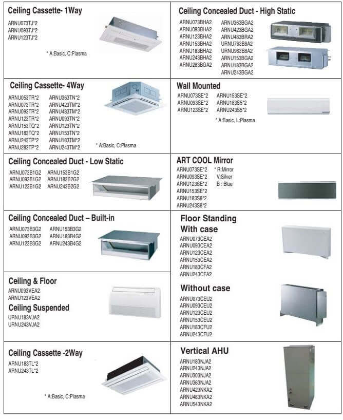
Error Code: 283
Description: Slave2 outdoor unit inverter DC link high voltage error
Error Code: 291
Description: Master outdoor unit inverter compressor overcurrent error
Error Code: 292
Description: Slave1 outdoor unit inverter compressor overcurrent error
Error Code: 293
Description: Slave2 outdoor unit inverter compressor overcurrent error
Error Code: 321
Description: Excessive increase in master outdoor unit inverter com- pressor1 gas discharge temperature
Error Code: 322
Description: Excessive increase in slave1 outdoor unit inverter com- pressor1 gas discharge temperature
Error Code: 323
Description: Excessive increase in slave2 outdoor unit inverter com- pressor1 gas discharge temperature
Error Code: 331
Description: Excessive increase in master outdoor unit inverter com- pressor2 gas discharge temperature
Error Code: 332
Description: Excessive increase in slave1 outdoor unit inverter com- pressor2 gas discharge temperature
Error Code: 333
Description: Excessive increase in slave2 outdoor unit inverter com- pressor2 gas discharge temperature
Error Code: 341
Description: Master outdoor unit compressor high pressure safety tripped
Error Code: 342
Description: Slave1 outdoor unit compressor high pressure safety tripped
Error Code: 343
Description: Slave2 outdoor unit compressor high pressure safety tripped
Error Code: 351
Description: Master outdoor unit low side pressure transducer sens- es pressure below allowable limits
Error Code: 352
Description: Slave1 outdoor unit low side pressure transducer sens- es pressure below allowable limits
Error Code: 353
Description: Slave1 outdoor unit low side pressure transducer sens- es pressure below allowable limits
Error Code: 361
Description: Master outdoor unit fell below low condenser (compression) ratio limit
Error Code: 362
Description: Slave1 outdoor unit fell below low condenser (compression) ratio limit
Error Code: 363
Description: Slave2 outdoor unit fell below low condenser (com- pression) ratio limit
Error Code: 401
Description: Master outdoor unit inverter compressor current trans- ducer (CT) sensor error
Error Code: 402
Description: Slave1 outdoor unit inverter compressor current trans- ducer (CT) sensor error
Error Code: 403
Description: Slave2 outdoor unit inverter compressor current trans- ducer (CT) sensor error
Error Code: 411
Description: Master outdoor unit inverter compressor1 discharge pipe temperature sensor error
Error Code: 412
Description: Slave1 outdoor unit inverter compressor1 discharge pipe temperature sensor error
Error Code: 413
Description: Slave2 outdoor unit inverter compressor1 discharge pipe temperature sensor error.
Error Code: 421
Description: Master outdoor unit low pressure transducer error
Error Code: 422
Description: Slave1 outdoor unit low pressure transducer error
Error Code: 423
Description: Slave2 outdoor unit low pressure transducer error
Error Code: 431
Description: Master outdoor unit high pressure transducer error
Error Code: 432
Description: Slave1 outdoor unit high pressure transducer error
Error Code: 433
Description: Slave2 outdoor unit high pressure transducer error
Error Code: 441
Description: Master outdoor unit ambient temperature sensor error
Error Code: 442
Description: Slave1 outdoor unit ambient temperature sensor error
Error Code: 443
Description: Slave2 outdoor unit ambient temperature sensor error
Error Code: 451
Description: Master outdoor unit heat exchanger pipe temperature sensor (front side, TH_HEX2) error
Error Code: 452
Description: Slave1 outdoor unit heat exchanger pipe temperature sensor (front side, TH_HEX2) error
Error Code: 453
Description: Slave2 outdoor unit heat exchanger pipe temperature sensor (front side, TH_HEX2) error
Error Code: 461
Description: Master outdoor unit suction pipe temperature sensor error
Error Code: 462
Description: Slave1 outdoor unit suction pipe temperature sensor error
Error Code: 463
Description: Slave2 outdoor unit suction pipe temperature sensor error
Error Code: 471
Description: Master outdoor unit inverter compressor2 discharge temperature sensor error
Error Code: 472
Description: Slave1 outdoor unit inverter compressor2 discharge temperature sensor error
Error Code: 473
Description: Slave2 outdoor unit inverter compressor2 discharge temperature sensor error
Error Code: 491
Description: Master outdoor unit IPM temperature sensor error
Error Code: 492
Description: Slave1 outdoor unit IPM temperature sensor error
Error Code: 493
Description: Slave2 outdoor unit IPM temperature sensor error
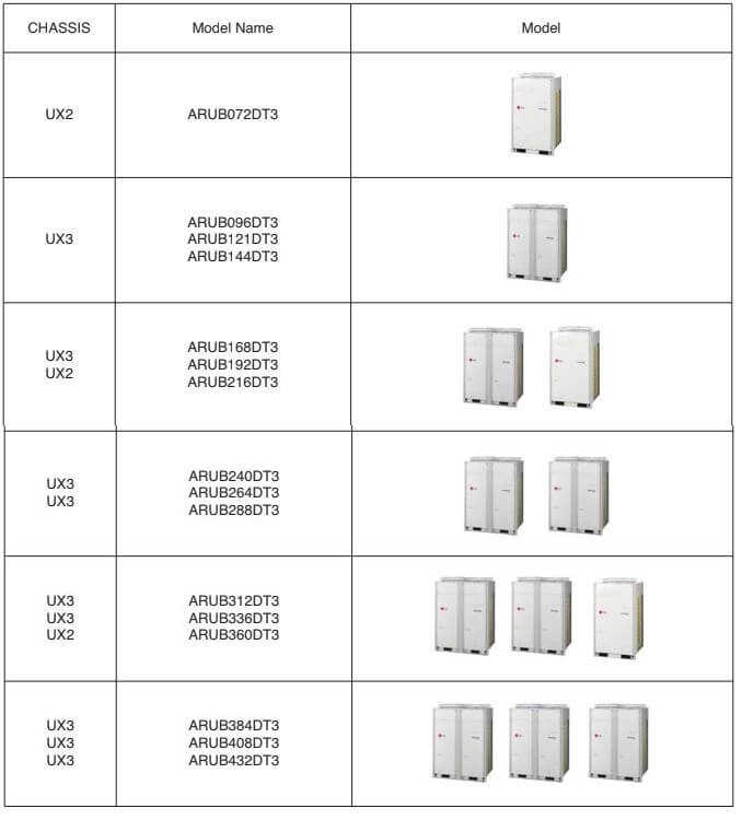
Error Code: 501
Description: Master outdoor unit three-phase power is not connected properly
Error Code: 502
Description: Slave1 outdoor unit three-phase power is not connected properly
Error Code: 503
Description: Slave2 outdoor unit three-phase power is not connected properly
Error Code: 511
Description: Combination ratio is out of range
Error Code: 512
Description: Total indoor unit capacity exceeds allowable heat recovery unit branch capacity
Error Code: 521
Description: Communication error between master outdoor unit inverter PCB and main PCB
Error Code: 522
Description: Communication error between slave1 outdoor unit inverter PCB and main PCB
Error Code: 523
Description: Communication error between slave2 outdoor unit inverter PCB and main PCB
Error Code: 531
Description: Communication error between outdoor unit main PCB and indoor unit(s) PCB
Error Code: 541
Description: Master outdoor unit power error
Error Code: 542
Description: Slave1 outdoor unit power error
Error Code: 543
Description: Slave2 outdoor unit power error
Error Code: 571
Description: Master outdoor unit main PCB and inverter PCB communication error
Error Code: 572
Description: Slave1 outdoor unit main PCB and inverter PCB communication error
Error Code: 573
Description: Slave2 outdoor unit main PCB and inverter PCB communication error
Error Code: 591
Description: Outdoor unit series installation error
Error Code: 601
Description: Master outdoor unit inverter PCB EPROM error
Error Code: 602
Description: Slave1 outdoor unit inverter PCB EPROM error
Error Code: 603
Description: Slave2 outdoor unit inverter PCB EPROM error
Error Code: 621
Description: High temperature at the master outdoor unit inverter heatsink
Error Code: 622
Description: High temperature at the slave1 outdoor unit inverter heatsink
Error Code: 623
Description: High temperature at the slave2 outdoor unit inverter heatsink
Error Code: 651
Description: Master outdoor unit inverter heatsink temperature sensor error
Error Code: 652
Description: Slave1 outdoor unit inverter heatsink temperature sensor error
Error Code: 653
Description: Slave2 outdoor unit inverter heatsink temperature sensor error
Error Code: 671
Description: Master outdoor unit fan has locked up
Error Code: 672
Description: Slave1 outdoor unit fan has locked up
Error Code: 673
Description: Slave2 outdoor unit fan has locked up
Error Code: 711
Description: Master outdoor unit converter CT sensor error
Error Code: 712
Description: Slave1 outdoor unit converter CT sensor error
Error Code: 713
Description: Slave2 outdoor unit converter CT sensor error
Error Code: 751
Description: Master outdoor unit fan CT sensor error
Error Code: 752
Description: Slave1 outdoor unit fan CT sensor error
Error Code: 753
Description: Slave2 outdoor unit fan CT sensor error
Error Code: 761
Description: Master outdoor unit fan DC link high voltage error
Error Code: 762
Description: Slave1 outdoor unit fan DC link high voltage error
Error Code: 763
Description: Slave2 outdoor unit fan DC link high voltage error
Error Code: 771
Description: Master outdoor unit fan overcurrent error
Error Code: 772
Description: Slave1 outdoor unit fan overcurrent error
Error Code: 773
Description: Slave2 outdoor unit fan overcurrent error
Error Code: 791
Description: Master outdoor unit fan operation failure error
Error Code: 792
Description: Slave1 outdoor unit fan operation failure error
Error Code: 793
Description: Slave2 outdoor unit fan operation failure error
Error Code: 861
Description: Master outdoor unit main PCB onboard EPROM error
Error Code: 862
Description: Slave1 outdoor unit main PCB onboard EPROM error
Error Code: 863
Description: Slave2 outdoor unit main PCB onboard EPROM error
Error Code: 871
Description: Master outdoor unit fan PCB EPROM error
Error Code: 872
Description: Slave1 outdoor unit fan PCB EPROM error
Error Code: 873
Description: Slave2 outdoor unit fan PCB EPROM error
Error Code: 1041
Description: Communication error between master outdoor unit and slave outdoor units
Error Code: 1042
Description: Communication error between slave1 outdoor unit and master and slave2 outdoor units
Error Code: 1043
Description: Communication error between slave2 outdoor unit and master and slave1 outdoor units
Error Code: 1051
Description: Master outdoor unit fan PCB to compressor PCB communication error
Error Code: 1052
Description: Slave1 outdoor unit fan PCB to compressor PCB communication error
Error Code: 1053
Description: Slave2 outdoor unit fan PCB to compressor PCB communication error
Error Code: 1061
Description: Master outdoor unit fan IPM error
Error Code: 1062
Description: Slave1 outdoor unit fan IPM error
Error Code: 1063
Description: Slave2 outdoor unit fan IPM error
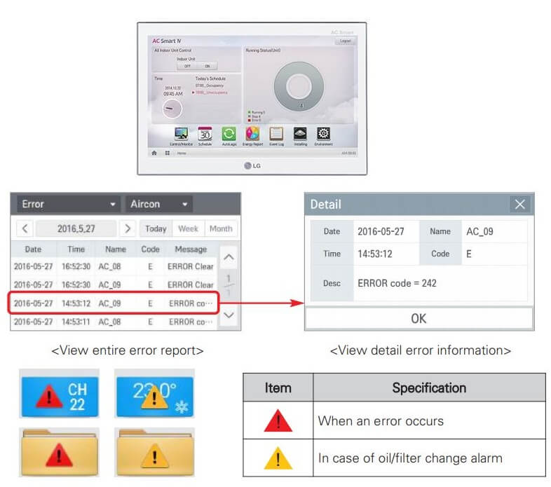
Error Code: 1071
Description: Master outdoor unit fan DC link low voltage error
Error Code: 1072
Description: Slave1 outdoor unit fan DC link low voltage error
Error Code: 1073
Description: Slave2 outdoor unit fan DC link low voltage error
Error Code: 1131
Description: Master outdoor unit liquid pipe temperature sensor error
Error Code: 1132
Description: Slave1 outdoor unit liquid pipe temperature sensor error
Error Code: 1133
Description: Slave2 outdoor unit liquid pipe temperature sensor error
Error Code: 1141
Description: Master outdoor unit subcooling inlet temperature sensor error
Error Code: 1142
Description: Slave1 outdoor unit subcooling inlet temperature sensor error
Error Code: 1143
Description: Slave2 outdoor unit subcooling inlet temperature sensor error
Error Code: 1151
Description: Master outdoor unit subcooling outlet temperature sensor error
Error Code: 1152
Description: Slave1 outdoor unit subcooling outlet temperature sensor error
Error Code: 1153
Description: Slave2 outdoor unit subcooling outlet temperature sensor error
Error Code: 1161
Description: Master outdoor unit oil level sensor error
Error Code: 1162
Description: Slave1 outdoor unit oil level sensor error
Error Code: 1163
Description: Slave2 outdoor unit oil level sensor error
Error Code: 1451
Description: Communication error between master outdoor unit main board and external board
Error Code: 1452
Description: Communication error between slave1 outdoor unit main board and external board
Error Code: 1453
Description: Communication error between slave2 outdoor unit main board and external board
Error Code: 1511
Description: Master outdoor unit operation mode conversion error
Error Code: 1512
Description: Slave1 outdoor unit operation mode conversion error
Error Code: 1513
Description: Slave2 outdoor unit operation mode conversion error
Error Code: 1531
Description: Master outdoor unit upper heat exchanger temperature sensor error
Error Code: 1532
Description: Slave1 outdoor unit upper heat exchanger temperature sensor error
Error Code: 1533
Description: Slave2 outdoor unit upper heat exchanger temperature sensor error
Error Code: 1541
Description: Master outdoor unit lower heat exchanger temperature sensor error
Error Code: 1542
Description: Slave1 outdoor unit lower heat exchanger temperature sensor error
Error Code: 1543
Description: Slave2 outdoor unit lower heat exchanger tempera- ture sensor error
Error Code: 1821
Description: Communication error between master outdoor unit external board main and sub MICOMs
Error Code: 1822
Description: Communication error between slave1 outdoor unit external board main and sub MICOMs
Error Code: 1823
Description: Communication error between slave2 outdoor unit external board main and sub MICOMs
Error Code: 1931
Description: Excessive increase in master outdoor unit fan heatsink temperature
Error Code: 1932
Description: Excessive increase in slave1 outdoor unit fan heat- sink temperature
Error Code: 1933
Description: Excessive increase in slave2 outdoor unit fan heat- sink temperature
Error Code: 1941
Description: Master outdoor unit fan heatsink temperature sensor error
Error Code: 1942
Description: Slave1 outdoor unit fan heatsink temperature sensor error
Error Code: 1943
Description: Slave2 outdoor unit fan heatsink temperature sensor error
Error Code: 2001
Description: Valve addressing error
Error Code: 2011
Description: Heat recovery unit liquid sensor error.
Error Code: 2021
Description: Heat recovery unit subcooling pipe inlet sensor error
Error Code: 2031
Description: Heat recovery unit subcooling pipe outlet sensor error
Error Code: 2041
Description: Communication error between outdoor unit and heat recovery unit
Error Code: 2051
Description: Communication error between heat recovery unit and the 485 modem
Error Code: 2061
Description: Duplicate address error of the heat recovery unit
Error Code: 51
Description: Capacity of indoor units connected to the heat recovery unit exceeds allowable limits
Note: To use open line 485 communication (9,600 bps communication), you need to use a product that is compatible with all of the “Generation 4” versions of the indoor units, heat recovery units, outdoor units, and accessories.
Q&A
-Error Code: CH50
Description: Outdoor unit three-phase power is not connected properly.
Details: One or more of R(L1), S(L2), T(L3) input power line connections is / are missing for the outdoor unit.
Causes:
1. Input voltage is not correct R(L1), S(L2), T(L3).
2. Power line connections may not be correct.
3. Main PCB may be damaged.
4. Inverter PCB input current sensor error.
LG Multi V Service Manual PDF
LG Multi V 5 Service Manual – VRF (Variable Refrigerant Flow) Outdoor Units 6.0 to 42.0 Tons.pdf
LG Multi V 4 Service Manual – Heat Pump and Heat Recovery Variable Refrigerant Flow Outdoor Units 6.0 to 42.0 Tons.pdf
LG AC Error Codes and Troubleshooting
*PLEASE SEND ME ANY COMMENT, SUGGESTION OR CORRECTION YOU MAY HAVE.
Описание кода ошибки 01 02 03 04 05 06 07 HL CL Po внутреннего блока кондиционеров LG
- 01
- произошло короткое замыкание термодатчика воздуха или обрыв в цепи;
- 02
- произошло короткое замыкание термодатчика испарителя или обрыв в цепи;
- 03
- нет обмена данными между пультом и внутренним блоком
- 04
- ошибка поплавкового датчика уровня конденсата или помпы (дренажной помпы);
- 05
- нет связи внешнего с внутренним блоком;
- 06
- произошло короткое замыкание термодатчика наружного блока или обрыв в цепи;
- 07
- некорректно установлены режимы внутренних блоков мультисистемы
- HL
- Нет ответа от датчика уровня
- CL
- Защита от детей активна, нажмите Timer & Min Buttons 3 секунды для отключения
- Po
- Активирован режим jet cool, нажмите jet cool для выхода
Описание кода ошибки 21 22 23 24 25 26 27 28 32 33 40 41 44 45 наружного блока кондиционеров LG
- 21
- Перегрузка компрессор по току;
- 22
- ток компрессора более 14 А;
- 23
- напряжение после модуля преобразования ниже 140 В;
- 24
- разомкнуты датчики и нижнего и верхнего давления;
- 25
- Величина напряжения выше или ниже нормы
- 26
- DC Compressor Position;
- 27
- Активна ошибка PSC (катушка индуктивности, реактор);
- 28
- DC Link High Volts;
- 32
- Превышена температура нагнетательной трубы (INV);
- 33
- Превышена температура нагнетательной трубы (Cons.);
- 40
- произошло короткое замыкание CT;
- 41
- термодатчик D-Pipe замкнут/оборван (INV);
- 44
- короткое замыкание или обрыв термодатчик наружного воздуха;
- 45
- короткое замыкание или обрыв термодатчик конденсатора;
Описание кода ошибки 46 47 48 51 52 53 54 60 61 61 63 65 67 105 внешнего блока кондиционеров LG
- 46
- короткое замыкание или обрыв датчик на всасывающей трубке;
- 47
- короткое замыкание или обрыв D-pipe датчик;
- 48
- короткое замыкание или обрыв D-pipe датчика и термодатчика воздуха;
- 51
- перегрузка по мощности комбинированного типа;
- 52
- произошла ошибка соединения (main micom-sub micom);
- 53
- произошла ошибка соединения (наружный-внутренний блоки);
- 54
- поменять фазу, неправильность последовательности фаз, для систем с трехфазным питанием;
- 60
- сбой памяти EEPROM (внутренней энергонезависимой памяти);
- 61
- трубка конденсатора (конденсер) имеет высокую температуру;
- 62
- радиатор имеет высокую температуру (вероятней всего, речь идет о радиаторе охлаждения инверторного силового модуля);
- 63
- конденсатор имеет низкую температуру;
- 65
- произошло замыкание/обрыв термодатчика;
- 67
- блокировка наружного BLDC (безколлекторного электродвигателя постоянного тока) вентилятора;
- 105
- управление вентилятором и главная плата управления не имеют между собой связи.
Описание кода ошибки CH1 CH2 CH4 CH5 CH5 CH7 CH8 CH9 CH10 CA CC CD Po Lo C1 C2 C4 C5 C6 C7 C8 C9 C10 кондиционеров LG Art Cool и кондиционеров LG настенного типа
- CH1 или C1
- выявлено к.з. внутреннего термодатчика воздуха или обрыв в цепи;
- CH2 или C2
- выявлено к.з. термодатчика испарителя или обрыв в цепи;
- CH4 или C4
- выявлено к.з. термодатчика конденсатора или обрыв в цепи;
- CH5 или C5
- соединение внешнего и внутреннего блоков в норме
- CH6 или C6
- перегрузка по току в цепи инверторного модуля
- CH7 или C7
- перегрузка по току компрессора
- CH8 или C8
- не вращается вентилятор внутреннего блока;
- CH9 или C9
- не вращается вентилятор внешнего блока;
- CH10 или C10
- терморезистор температурного контроля компрессора Сплит системы неисправен (выявлено к.з. или обрыв);
- CA
- температура нагнетания более 130 C;
- CC
- сбой памяти EEPROM (внутренней энергонезависимой памяти);
- CD
- выявлен сбой в модуле инвертора;
- Po
- система перешла в режим энергосбережения;
- Lo
- система перешла в режим тестирования.
Система диагностики LGMV
LGMV — является специально разработанным компанией LG мобильным приложением для удаленного мониторинга параметров работы систем кондиционирования LG. Приложение разработано с целью облегчения процедуры обслуживания оборудования кондиционерных систем и предназначено для инженеров сервисных центров. Алгоритмы анализа состояния системы основаны на многолетнем опыте наблюдения за циклом эксплуатации кондиционеров. Основной функцией приложения является оперативное определение отклонений рабочих параметров и выдача мгновенных рекоммендаций для устранения выявленных проблем.
Благодаря системе диагностики LGMV обеспечивается контроль рабочих параметров и заблаговременное предупреждение возникновения неисправностей что значительно увеличивает срок службы. С помощью приложения LGMV время диагностики и пуско-наладочных работ сократилось в разы. Кондиционерные системы оснащаются беспроводным коммуникационным модулем и в свободном доступе есть бесплатное приложение для смартфонов. Для того чтобы начать использовать мобильное приложение LGMV необходим эксклюзивный модуль Bluetooth, который необходимо подключить в разъем CN-LGMV на главной управляющей плате наружного блока.
Перечень основных функций LGMV:
Индикация основной информации о работе кондиционера. Отображение информации о величине давления и прочих характеристик в графическом виде. При подключении модуля к наружному блоку возможность изменения режимов работы внутреннего блока. Возможность экспорта данных о работе кондиционера в файл. Формирование отчета о тестировании в html-документ. Отображение кода ошибки и возможность сразу найти ее описание в списке из PDF-документа.
Мобильное приложение LGMV доступно для скачивания в Google Play в качестве инструмента для техобслуживания, и ускорения поиска проблем в работе систем кондиционирования LG. Мобильное приложение LGMV использует минимум ресурсов смартфона и моментально обрабатывает данные. Однако в случае использования смартфона со слабыми характеристиками мониторинг может происходить с задержкой, а экспортируемые данные сохранятся неполностью.
Желательно для работы с приложением LGMV использовать производительный смартфон и при этом лучше позакрывать все остальные приложения для избежания сбоев мониторинга.
Объем передачи данных может составлять десятки мегабайт поэтому располагайте смартфон на наиболее коротком расстоянии от модуля Bluetooth.
LG Fault Codes
- CH 01 – Indoor Unit Ambient Sensor Malfunction
- CH 02 – Indoor Unit Pipe Inlet Sensor Malfunction
- CH 06 – Indoor Unit Pipe Outlet Sensor Malfunction
- CH 03 – Communication Error Between Indoor Unit and Remote Control
- CH 04 – Drainage Pump Malfunction
- CH 05 – Indoor unit – Outdoor unit communication error
- CH 07 – Not all indoor units work in the same mode on HP devices
- CH 09 – Indoor unit EEPROM malfunction
- CH 10 – Indoor unit BLDC fan motor malfunction
- CH 11 – Indoor unit communication error
- CH 21 – Inverter PVB IPM failure (appears as 211 on VRF Master, 212 on Slave 1, 213 on Slave 2, 214 on Slave 3)

- CH 22 – AC input overcurrent failure (appears as 211 on VRF Master, 212 on Slave 1, 213 on Slave 2, 214 on Slave 3)
- CH 23 –Inv Compressor DC Link low voltage (appears as 211 on VRF Master unit, 212 on Slave 1, 213 on Slave 2, 214 on Slave 3)
- CH 24 –Compressor output head too high (Main outdoor unit 24, Slave1 109, Slave2 140 Slave3 153)
- CH 25 – Input voltage high or low
- CH 26 – Inv Compressor first operation failure (Master 261, Slave1 262, Slave2 263, Slave3 264)
- CH 27 – PSC error


- CH 43 – High pressure sensor failure (Master 431, Slave1 432, Slave2 433, Slave3 434)
- CH 44 – Outdoor unit ambient sensor faulty (Master 441, Slave1 442, Slave2 443, Slave3 444)
- CH 45 – Condenser pipe sensor defective (Master 451, Slave1 452, Slave2 453, Slave3 454)
- CH 46 – Compressor suction temperature thermistor defective
- CH 47 – Constant1 Compressor outlet pipe temperature sensor malfunction (Master 471, Slave1 472, Slave2 443, Slave3 474)
- CH 48 – Constant 2 Compressor outlet pipe temperature sensor failure (Master 481, Slave1 482, Slave2 483, Slave3 484)
- CH 49 – Outdoor unit IPM temperature sensor defective
- CH 50 – Outdoor unit phase connection error (Master 501, Slave1 502, Slave2 503, Slave3 504)
- CH 51 – Capacity Excess
- CH 52 – Communication error between inverter PCB and main PCB (Master 521, Slave1 522, Slave2 522, Slave3 523)
- CH 53 – İç ünite ile dış ünite ana PCB arasında haberleşme hatası
- CH 54 – The phase connections are missing or in the wrong order (Master 541, Slave1 542, Slave2 543, Slave3 544)


- CH 57 – Communication error between main PCB and inverter PCB (Master 571, Slave 572, Slave2 573, Slave3 574)
- CH 59 – Plus connection error (Master 591, Slave1 592, Slave2 593, Slave3 594)
- CH 60 – Inverter PCB EEPROM error (Master 601, Slave1 602, Slave2 603, Slave3 604)
- CH 61 – Condenser pipe sensor temperature load
- CH 62 – Heat sink sensor overheat
- CH 65 – Heat sink sensor open or short circuit
- CH 67 – Outdoor unit fan locked (Master 671, Slave1 672, Slave2 673, Slave3 674)
- CH 69 – Constant 1 Compressor CT Sensor failure (Master 691, Slave1 692, Slave2 693, Slave3 694)
- CH 70 – Stationary 2 Compressor CT Sensor failure (Master 701, Slave1 702, Slave2 703, Slave3 704)
- CH 73 – AC input surge current failure (Master 731, Slave1 732, Slave2 733, Slave3 734)
- CH 75 – Fan CT sensor fault (Master 751, Slave1 752, Slave2 753, Slave3 754)
- CH 76 – Fan DC link high voltage error (Master 761, Slave1 762, Slave2 763, Slave3 764)
- CH77 – Fan overcurrent fault (Master 771, Slave1 772, Slave2 773, Slave3 774)


- CH 79 – Fan initial start error (Master 791, Slave1 792, Slave2 793, Slave3 794)
- CH 86 – Main PCB EEPROM failure (Master 861, Slave1 862, Slave2 863, Slave3 864)
- CH 87 – Fan PCB EEPROM failure (Master 871, Slave1 872, Slave2 873, Slave3 874)
- CH 104 – Communication error between outdoor units (Master 11- & gt; 041, Slave1 12- & gt; 042, Slave2 13- & gt; 043, Slave3 14- & gt; 044)
- CH 105 – Communication error between fan PCB and inverter PCB (Master 11 – & 051, Slave1 12 – 05 052, Slave2 13- & 053, Slave3 14 – 05 054)
- CH 106 – Outdoor Unit Fan PCB IPM Error
- CH 107 – Fan DC link low voltage fault (Master 11 – 07 071, Slave1 12 – 07 072, Slave2 13 – 07 073, Slave3 14 – 07 074)
- CH 113 – Outdoor Unit Liquid pipe (condenser) temperature sensor faulty (Master 11- 131 131, Slave1 12 – 132 132, Slave2 13 – 133 133, Slave3 14 – 134 134)
- CH 115 – Outdoor unit subcool output temperature sensor failure (Master 11 – & gt; 151, Slave1 12 – & gt; 152, Slave2 13- & gt; 153, Slave3 14 – & gt; 154
- CH 173 – Outdoor unit constant1 compressor overcurrent (Master 11 – 73 731, Slave1 12 – 7 732, Slave2 13 – 7 733, Slave3 14 – 73 734)
- CH 174 – Outdoor unit constant2 compressor overcurrent (Master 11 – 74 741, Slave1 12 – 74 742, Slave2 13 – 74 743, Slave3 14 – 74 744)


- CH 182 – Master Outdoor Unit main PCB to auxiliary PCB communication error
- CH 184 – Oil compensating pipe temperature sensor malfunction (Master (11-841), Slave1 (12-842), Slave2 (13-843), Slave3 (14-844)
- CH 185 – Oil compensating pipe temperature sensor malfunction (Master (11-851), Slave1 (12-852), Slave2 (13-853), Slave3 (14-854)
- CH 186 – Oil compensating pipe temperature sensor malfunction (Master (11-861), Slave1 (12-862), Slave2 (13-863), Slave3 (14-864)
- CH 193 – Fan PCB Heatsink temperature is high (Master 11 – 93 931, Slave1 12- 9 932, Slave2 – 9 933, Slave3 14- 93 934)
- CH 194 – Fan PCB heatsink temperature sensor faulty (Master 11 – 94 941, Slave1 12 – 94 942, Slave2 13 – 94 943, Slave3 14 – 94 944)
- CH 242 – Network Failure

Address : Altınsehir Neighborhood Kelebek St. No:27 Umraniye / Istanbul
Phone : +90 (216) 336 72 71
Fax : +90 (216) 336 72 71
E-posta : info@zenta.com.tr
Какая ошибка у вашего кондиционера?
Код ошибки: CH-01
Датчик температуры воздуха в помещении неисправен
Короткое замыкание в цепи датчика, обрыв цепи датчика. Попадание влаги в датчик, Неисправен контакт в разъеме, Вышла из строя плата управления
Код ошибки: CH-02
Датчик температуры хладагента, который находится при входе в теплообменник, неисправен
Короткое замыкание в цепи датчика, обрыв цепи датчика. Попадание влаги в датчик, Неисправен контакт в разъёме, Вышла из строя плата управления
Код ошибки: CH-03
Нет соединение с проводным пультом
Плохой контакт на плату управления в пульте управления, окисление контактов, перестал функционировать пульт управления, не работает плата управления ( то есть компоненты, отвечающие за соединение с пультом управления)
Проверьте провода пульта управления на наличие повреждений. — Проверьте состояние контактов в разъёме подключения соединительного провода на плате и на ПУ — Необходимо прозвонить соединительный провод — Убедиться что пульт управления исправен и работоспособен — Убедиться что плата управления цела.
Код ошибки: CH-04
Не работает дренажный насос
Дренажный шланг может быть забит, двигатель насоса неисправен, цепь поплавкового датчика разомкнута
Проверить двигатель дренажного насоса на исправность, оценить состояние дренажного шланга, проверить правильность установки дренажного насоса
Решение не помогло или нужно больше информации?
Проконсультируйтесь со специалистом или вызовите мастера!
Код ошибки: CH-05
В связи между внутренним и наружным блоком присутствует ошибка
Отсутствует питание на внутреннем или наружном блоке, ошибка подключения кабеля питания. Мотор вентилятора вышел из строя. Ошибка связи из-за внешних помех, если рядом пролегает электрический кабель.
Прежде всего проверить подключения кабеля, проверить наличие напряжения на плате управления блоков. Проверить исправность двигателя вентилятора.
Код ошибки: CH-06
Датчик, который расположен на выходе из теплообменника внутреннего блока, неисправен
Короткое замыкание в цепи датчика, обрыв цепи датчика. Попадание влаги в датчик, Неисправен контакт в разъёме, Вышла из строя плата управления
Код ошибки: CH-07
Ошибка EEPROM (ПЗУ)
Неисправен контакт ПЗУ на плате управления
Необходимо проверить контакт и правильность установки чипа ПЗУ
Код ошибки: CH-10
Неисправность БДПТ электродвигателя вентилятора внутреннего блока
Остановка вентилятора из-за внешнего воздействия — Плохой контакт в разъёме на плате управления — Неисправность двигателя — Плата неисправна
Устраните внешние воздействия — Проверьте контакт разъёма — Проверьте двигатель вентилятора — Проверьте плату управления
Код ошибки: CH-12
Датчик, который находится в центральной части теплообменника внутреннего блока, неисправен
Короткое замыкание в цепи датчика, обрыв цепи датчика. Попадание влаги в датчик, Неисправен контакт в разъёме, Вышла из строя плата управления
Код ошибки: СН21
Повышенный потребляемый ток компрессора с инверторным приводом
— Утечка хладагента — Компрессор заклинен — Плата инвертора неисправна
— Проверьте контур на возможность утечки хладагента — Проверить на неисправность силовые элементы платы управления компрессором — Проверить цепь электродвигателя компрессора на предмет обрывов и короткого замыкания
Код ошибки: СН22
Перегрузка. Повышенный потребляемый ток наружного блока
Загрязненный теплообменник наружного блока, низкая циркуляция охлаждающего воздуха в месте установки наружного блока (есть помехи для теплообмена, вентилятор загражден). Также причиной может являться низкое напряжение у источника питания
— Проверить напряжение источника питания — Проверить циркуляцию охлаждающего воздуха в месте, где установлен наружный блок (проверить, чтобы блоку ничего не мешало проводить теплообмен). — Прочистить фильтр внутреннего блока и теплообменник наружного блока
Код ошибки: СН23
Слишком низкое или высокое напряжение сети
Плата управления компрессором неисправна, низкое напряжение у источника питания, Плохо закреплен провод
Проверить качество подключения к источнику питания. Проверить подключения проводов реактора. Проверить датчик напряжение на исправность
Код ошибки: СН26
При запуске компрессора возникает неисправность
Компрессор вышел из строя, плата управления компрессором неисправна, На разъеме компрессора присутствует дефект провода
— Проверить провода компрессора на наличие дефектов — Проверить плату управления компрессора на работоспособность
Код ошибки: СН27
Перегрузка тока в цепи конвектора (преобразователя тока AC –DC)
— Работа кондиционера на перегрузках, недостаточная циркуляция воздуха в местах крепления внешнего блока кондиционера — Повреждение элементов выпрямителя PSC в плате управления — Неверные характеристики реактора
— Проверить циркуляцию воздуха в районе наружного блока — Проверить характеристики реактора
Код ошибки: СН32
Температура выше нормы нагнетания компрессора
-Датчик, который отвечает за измерение температуры нагнетания, неисправен — Утечка или недостаточное количество хладагента — Плохие контакты разъемов
-Проверить в местах крепления наружного блока хорошую циркуляцию воздуха — Поверить количество хладагента в системе, исключить утечку — Проверить датчик температуры нагнетания на исправность, проверить подключения разъемов к плате управления
Код ошибки: СН34
Высокое давление хладагента в системе
Циркуляция воздуха через теплообменник затруднена (фильтр внутреннего блока загрязнен, в случае работы в режиме охлаждения или обмерзший теплообменник наружного блока в случае работы в режиме обогрева) — Количество хладагента в системе меньше допустимой нормы — Проблемы с платой управления — Разъемы неисправны
Проверить в местах крепления наружного блока хорошую циркуляцию воздуха — Поверить количество хладагента в системе, исключить утечку — Проверить датчик температуры нагнетания на исправность — Проверить подключения разъемов к плату управления — Прочистить фильтры при условии их загрязнения
Код ошибки: CH35
Низкое давление хладагента в системе
— Циркуляция воздуха через теплообменник затруднена (фильтр внутреннего блока загрязнен, в случае работы в режиме охлаждения или обмерзший теплообменник наружного блока в случае работы в режиме обогрева) — Количество хладагента в системе меньше допустимой нормы — Проблемы с платой управления — Разъемы неисправны
— Проверить в местах крепления наружного блока хорошую циркуляцию воздуха — Поверить количество хладагента в системе, исключить утечку — Проверить датчик температуры нагнетания на исправность — Проверить подключения разъемов к плату управления — Прочистить фильтры при условии их загрязнения
Код ошибки: СН41
Датчик температуры нагнетания инверторного компрессора неисправен
— В цепи датчика случился обрыв или короткое замыкание — Отходит контакт в разъеме на блоке управления — Неисправность платы управления
— Проверить разъемы датчиков — Проверить сопротивление датчика: — СН41 — 200 кОм при 25°C (при отключенном датчике) — СН44 -10 кОм при 25°C (при отключенном от платы датчике) — СН45/48 — 5 кОм при 25°C (при отключенном от платы датчике) — СН46 — 5 кОм при 25°C (при отключенном от платы датчике)
Код ошибки: СН44
Неисправность датчика температуры уличного воздуха
— В цепи датчика случился обрыв или короткое замыкание — Отходит контакт в разъеме на блоке управления — Неисправность платы управления
— Проверить разъемы датчиков — Проверить сопротивление датчика: — СН41 — 200 кОм при 25°C (при отключенном датчике) — СН44 -10 кОм при 25°C (при отключенном от платы датчике) — СН45/48 — 5 кОм при 25°C (при отключенном от платы датчике) — СН46 — 5 кОм при 25°C (при отключенном от платы датчике)
Код ошибки: СН45/48
Неисправность или ошибка датчика температуры трубки теплообменника наружного блока кондиционера
— В цепи датчика случился обрыв или короткое замыкание — Отходит контакт в разъеме на блоке управления — Неисправность платы управления
— Проверить разъемы датчиков — Проверить сопротивление датчика: — СН41 — 200 кОм при 25°C (при отключенном датчике) — СН44 -10 кОм при 25°C (при отключенном от платы датчике) — СН45/48 — 5 кОм при 25°C (при отключенном от платы датчике) — СН46 — 5 кОм при 25°C (при отключенном от платы датчике)
Код ошибки: СН46
Ошибка датчика температуры на линии всасывания компрессора
— В цепи датчика случился обрыв или короткое замыкание — Отходит контакт в разъеме на блоке управления — Неисправность платы управления
— Проверить разъемы датчиков — Проверить сопротивление датчика: — СН41 — 200 кОм при 25°C (при отключенном датчике) — СН44 -10 кОм при 25°C (при отключенном от платы датчике) — СН45/48 — 5 кОм при 25°C (при отключенном от платы датчике) — СН46 — 5 кОм при 25°C (при отключенном от платы датчике)
Код ошибки: СН61
Температура конденсации превышает норму
Работа наружного блока в недостаточной циркуляции воздуха, что способствует перегрузкам. Теплообменник загрязнен. Неисправность датчика температуры конденсации
Проверить и обеспечить нормальную циркуляцию воздуха в местах крепления наружного блока кондиционера. Проверить не перезаправлена ли система фреоном. Проверить корректность установки термодатчика
Код ошибки: СН62
Перегрев радиатора силового транзистора на плате управления компрессором
— Вентилятор наружного блока кондиционера заклинил — Неправильное место установки наружного блока — Неисправность контура — Неисправность датчика температуры
— Проверьте состояние вентилятора наружного блока — Проверьте место установки наружного блока — Проверьте разъём соединения датчика — Проверьте контур датчика на плате управления компрессором
Код ошибки: СН67
Неисправность электродвигателя вентилятора наружного блока
— Вентилятор заклинил по механическим причинам — Электродвигатель вентилятора вышел из строя
— Проверить есть ли помеха работе вентилятора внешними предметами — Оценить работоспособность двигателя вентилятора — Проверьте плату управления (элементы контура управления вентилятором)
Код ошибки: СН72
Неисправность при переключении 4-х ходового клапана
— Разомкнут разъём подключения на плате — Привод 4-х ходового разомкнут, либо замкнут — Проблема платы управления
— Проверьте функциональность подключения на плате управления — Проверьте сопротивление катушки привода — Проверьте напряжение на плате управления
ERROR CODES
Please refer to the Safety Precautions on pages 4-7 for more detail to prevent injury or death regarding the operation and service
WARNING
troubleshooting of the Multi V product.
Error No.
Description
150
Outdoor unit
compressor
Master: 1501
discharge
superheat not
Slave 1: 1502
satisfied.
Slave 2: 1503
Is there an indoor unit
that is leaking a large amount of
refrigerant?*
Yes
Is the EEV coil assembly
correct?
Yes
Are the EEV connections
correct?
Yes
Replace EEV assembly.
*Excessive refrigerant leak: Both the piping inlet and outlet temperatures are <50°F when the indoor unit is off (EEV 40 pulses). Also, a loud
refrigerant flow noise was heard.
192
Code indicates that based on current superheat measurements,
there is a high possibility of liquid refrigerant flooding back and
damaging the compressor.
Code can only occur when the outdoor is operating in cooling mode
(all indoor units must be in cooling mode; error cannot occur during
simultaneous operation).
The first time superheat falls <4.8ºF (<3ºC) for 5 minutes, the sys-
tem will shut down and CH150 is displayed on all indoor unit zone
sensors and central control devices. After the initial occurrence, the
outdoor unit cycles off and will auto-restart.
Following the initial restart, and after 10 minutes of operation to al-
low the system time to stabilize, if the superheat again falls <4.8°F
(<3ºC) for 5 minutes, the system will shut down and auto restart for
a second time.
If error occurs 3 times within any 1 hour period of compressor oper-
ation, the error code will be assigned a Level 3, and the system will
shut down and remain off. A manual restart will be necessary.
No
The compressor EEV or circuit
Replace the compressor EEV
or EEV assembly.
No
Re-assemble or replace the
EEV coil.
No
Connect EEV connections.
Due to our policy of continuous product innovation, some specifications may change without notification.
©LG Electronics U.S.A., Inc., Englewood Cliffs, NJ. All rights reserved. «LG» is a registered trademark of LG Corp.
Details
No
leaking?
Yes
Causes
After at least 10 minutes of
compressor operation, the master
outdoor unit microprocessor will
calculate the system’s compressor
superheat. If at any time during
compressor operation where all
indoor units in thermal on are in
cooling mode and the compressor
superheat falls <4.8°F (<3ºC) for
bility that liquid could flood back to
the inlet of the compressor scroll,
resulting in compressor damage.
1. Indoor unit EEV has disconnect-
ed or short circuited.
2. Defective compressor EEV
(large refrigerant leak has
occurred).
3. Defective liquid piping and / or
vapor piping connections.
Check liquid and vapor piping
connections.
—
LG is one of the leading multinational companies based in South Korea. What started as a small venture has now turned into a billion-dollar empire that focuses on a wide range of technology-based sectors. Offering customers all that they can need from air conditioning, TVs, washing machines, to state-of-the-art AI systems. Making sure you get a quality built and desirable appliance that enhances your everyday life.
LG VRF is said to be one of the most powerful and versatile air conditioners, offering you a cost-effective and easy-to-install a system that will help you eradicate all your issues. Offering both indoor and outdoor units, it can help you set up the right way. Their VRF system is designed to help you minimize efficiency losses while providing you sustainable energy benefits. Additionally, it aims to provide you with comfort, reliability, energy efficiency, and smart solutions for your space.
With such a huge system comes a chance of error in function. Fortunately, the system offers you with specific error codes you can use to regain effective working. Start by noting down the error code, and match it using the list below. Once you have the error code you can easily work your way to the fix. To help you out we have listed down some of the most common error codes for LG VRF.
Error Codes;
- Indicate different types of unit failures, assist in self-diagnosis and to track the frequency of occurrence.
- Error codes are shown on the LED of indoor units, wired remote controller, the outdoor unit control board, and on the main screen of the LG Monitoring View (LGMV) Diagnostic Software.
- If two or more errors occur simultaneously, the lower error code number is displayed first.
- After error is resolved, the error code does not display.
Error Display;
The first, second, and third number on the LED indicates error number; the fourth number on LED indicates outdoor unit number.
Examples: 211 = Error No. 21 on master unit, 213 = Error No. 21 on slave2 unit, Error No. 105 on master unit on compressor 1.
Error Code Nomenclature Definitions;
- MICOM: Non-volatile memory chip where unit setup information is stored.
- EPROM: Non-volatile memory chip where device identification, size, and factory defined default component operating parameters are stored.
| Error Codes | Description |
|---|---|
| 01 | Indoor unit return air or optional remote wall temperature sensor communications error |
| 02 | Indoor unit inlet pipe temperature sensor communication error |
| 03 | Communication error between zone controller and indoor unit |
| 04 | Condensate float switch error |
| 05 | Communication error between outdoor unit and indoor unit |
| 06 | Indoor unit outlet pipe temperature sensor error |
| 07 | Indoor units are not operating in the same mode |
| 09 | Indoor unit EPROM error |
| 10 | Indoor unit BLDC fan motor communications error |
| 211 | Master outdoor unit inverter compressor PCB error |
| 212 | Slave1 outdoor unit inverter compressor PCB error |
| 213 | Slave2 outdoor unit inverter compressor PCB error |
| 221 | Master outdoor unit inverter board input overcurrent (RMS) error |
| 222 | Slave1 outdoor unit inverter board input overcurrent (RMS) error |
| 223 | Slave2 outdoor unit inverter board input overcurrent (RMS) error |
| 231 | Low DC voltage sensed at the master outdoor unit inverter compressor DC link |
| 232 | Low voltage to the slave1 outdoor unit inverter compressor DC link |
| 233 | Low voltage to the slave2 outdoor unit inverter compressor DC link |
| 241 | Master outdoor unit high pressure switch error |
| 242 | Slave1 outdoor unit high pressure switch error |
| 243 | Slave2 outdoor unit high pressure switch error |
| 251 | Input voltage to the master outdoor unit is too high or too low |
| 252 | Input voltage to the slave1 outdoor unit is too high or too low |
| 253 | Input voltage to the slave2 outdoor unit is too high or too low |
| 261 | Master outdoor unit inverter compressor operation error |
| 262 | Slave1 outdoor unit inverter compressor operation error |
| 263 | Slave2 outdoor unit inverter compressor operation error |
| 281 | Master outdoor unit inverter DC link high voltage error |
| 282 | Slave1 outdoor unit inverter DC link high voltage error |
Other Codes:
- 283 Slave2 outdoor unit inverter DC link high voltage error
- 291 Master outdoor unit inverter compressor overcurrent error
- 292 Slave1 outdoor unit inverter compressor overcurrent error
- 293 Slave2 outdoor unit inverter compressor overcurrent error
- 321 Excessive increase in master outdoor unit inverter com- pressor1 gas discharge temperature
- 322 Excessive increase in slave1 outdoor unit inverter com- pressor1 gas discharge temperature
- 323 Excessive increase in slave2 outdoor unit inverter com- pressor1 gas discharge temperature
- 331 Excessive increase in master outdoor unit inverter com- pressor2 gas discharge temperature
- 332 Excessive increase in slave1 outdoor unit inverter com- pressor2 gas discharge temperature
- 333 Excessive increase in slave2 outdoor unit inverter com- pressor2 gas discharge temperature
- 341 Master outdoor unit compressor high pressure safety tripped
- 342 Slave1 outdoor unit compressor high pressure safety tripped
- 343 Slave2 outdoor unit compressor high pressure safety tripped
- 351 Master outdoor unit low side pressure transducer sens- es pressure below allowable limits
- 352 Slave1 outdoor unit low side pressure transducer sens- es pressure below allowable limits
- 353 Slave1 outdoor unit low side pressure transducer sens- es pressure below allowable limits
- 361 Master outdoor unit fell below low condenser (compression) ratio limit
- 362 Slave1 outdoor unit fell below low condenser (compression) ratio limit
- 363 Slave2 outdoor unit fell below low condenser (com- pression) ratio limit
- 401 Master outdoor unit inverter compressor current trans- ducer (CT) sensor error
- 402 Slave1 outdoor unit inverter compressor current trans- ducer (CT) sensor error
- 403 Slave2 outdoor unit inverter compressor current trans- ducer (CT) sensor error
- 411 Master outdoor unit inverter compressor1 discharge pipe temperature sensor error
- 412 Slave1 outdoor unit inverter compressor1 discharge pipe temperature sensor error
- 413 Slave2 outdoor unit inverter compressor1 discharge pipe temperature sensor error.
- 421 Master outdoor unit low pressure transducer error
- 422 Slave1 outdoor unit low pressure transducer error
- 423 Slave2 outdoor unit low pressure transducer error
- 431 Master outdoor unit high pressure transducer error
- 432 Slave1 outdoor unit high pressure transducer error
- 433 Slave2 outdoor unit high pressure transducer error
- 441 Master outdoor unit ambient temperature sensor error
- 442 Slave1 outdoor unit ambient temperature sensor error
- 443 Slave2 outdoor unit ambient temperature sensor error
- 451 Master outdoor unit heat exchanger pipe temperature sensor (front side, TH_HEX2) error
- 452 Slave1 outdoor unit heat exchanger pipe temperature sensor (front side, TH_HEX2) error
- 453 Slave2 outdoor unit heat exchanger pipe temperature sensor (front side, TH_HEX2) error
- 461 Master outdoor unit suction pipe temperature sensor error
- 462 Slave1 outdoor unit suction pipe temperature sensor error
- 463 Slave2 outdoor unit suction pipe temperature sensor error
- 471 Master outdoor unit inverter compressor2 discharge temperature sensor error
- 472 Slave1 outdoor unit inverter compressor2 discharge temperature sensor error
- 473 Slave2 outdoor unit inverter compressor2 discharge temperature sensor error
- 491 Master outdoor unit IPM temperature sensor error
- 492 Slave1 outdoor unit IPM temperature sensor error
- 493 Slave2 outdoor unit IPM temperature sensor error
- 501 Master outdoor unit three-phase power is not connected properly
- 502 Slave1 outdoor unit three-phase power is not connected properly
- 503 Slave2 outdoor unit three-phase power is not connected properly
- 511 Combination ratio is out of range
- 512 Total indoor unit capacity exceeds allowable heat recovery unit branch capacity
- 521 Communication error between master outdoor unit inverter PCB and main PCB
- 522 Communication error between slave1 outdoor unit inverter PCB and main PCB
- 523 Communication error between slave2 outdoor unit inverter PCB and main PCB
- 531 Communication error between outdoor unit main PCB and indoor unit(s) PCB
- 541 Master outdoor unit power error
- 542 Slave1 outdoor unit power error
- 543 Slave2 outdoor unit power error
- 571 Master outdoor unit main PCB and inverter PCB communication error
- 572 Slave1 outdoor unit main PCB and inverter PCB communication error
- 573 Slave2 outdoor unit main PCB and inverter PCB communication error
- 591 Outdoor unit series installation error
- 601 Master outdoor unit inverter PCB EPROM error
- 602 Slave1 outdoor unit inverter PCB EPROM error
- 603 Slave2 outdoor unit inverter PCB EPROM error
- 621 High temperature at the master outdoor unit inverter heatsink
- 622 High temperature at the slave1 outdoor unit inverter heatsink
- 623 High temperature at the slave2 outdoor unit inverter heatsink
- 651 Master outdoor unit inverter heatsink temperature sensor error
- 652 Slave1 outdoor unit inverter heatsink temperature sensor error
- 653 Slave2 outdoor unit inverter heatsink temperature sensor error
- 671 Master outdoor unit fan has locked up
- 672 Slave1 outdoor unit fan has locked up
- 673 Slave2 outdoor unit fan has locked up
- 711 Master outdoor unit converter CT sensor error
- 712 Slave1 outdoor unit converter CT sensor error
- 713 Slave2 outdoor unit converter CT sensor error
- 751 Master outdoor unit fan CT sensor error
- 752 Slave1 outdoor unit fan CT sensor error
- 753 Slave2 outdoor unit fan CT sensor error
- 761 Master outdoor unit fan DC link high voltage error
- 762 Slave1 outdoor unit fan DC link high voltage error
- 763 Slave2 outdoor unit fan DC link high voltage error
- 771 Master outdoor unit fan overcurrent error
- 772 Slave1 outdoor unit fan overcurrent error
- 773 Slave2 outdoor unit fan overcurrent error
- 791 Master outdoor unit fan operation failure error
- 792 Slave1 outdoor unit fan operation failure error
- 793 Slave2 outdoor unit fan operation failure error
- 861 Master outdoor unit main PCB onboard EPROM error
- 862 Slave1 outdoor unit main PCB onboard EPROM error
- 863 Slave2 outdoor unit main PCB onboard EPROM error
- 871 Master outdoor unit fan PCB EPROM error
- 872 Slave1 outdoor unit fan PCB EPROM error
- 873 Slave2 outdoor unit fan PCB EPROM error
- 1041 Communication error between master outdoor unit and slave outdoor units
- 1042 Communication error between slave1 outdoor unit and master and slave2 outdoor units
- 1043 Communication error between slave2 outdoor unit and master and slave1 outdoor units
- 1051 Master outdoor unit fan PCB to compressor PCB communication error
- 1052 Slave1 outdoor unit fan PCB to compressor PCB communication error
- 1053 Slave2 outdoor unit fan PCB to compressor PCB communication error
- 1061 Master outdoor unit fan IPM error
- 1062 Slave1 outdoor unit fan IPM error
- 1063 Slave2 outdoor unit fan IPM error
- 1071 Master outdoor unit fan DC link low voltage error
- 1072 Slave1 outdoor unit fan DC link low voltage error
- 1073 Slave2 outdoor unit fan DC link low voltage error
- 1131 Master outdoor unit liquid pipe temperature sensor error
- 1132 Slave1 outdoor unit liquid pipe temperature sensor error
- 1133 Slave2 outdoor unit liquid pipe temperature sensor error
- 1141 Master outdoor unit subcooling inlet temperature sensor error
- 1142 Slave1 outdoor unit subcooling inlet temperature sensor error
- 1143 Slave2 outdoor unit subcooling inlet temperature sensor error
- 1151 Master outdoor unit subcooling outlet temperature sensor error
- 1152 Slave1 outdoor unit subcooling outlet temperature sensor error
- 1153 Slave2 outdoor unit subcooling outlet temperature sensor error
- 1161 Master outdoor unit oil level sensor error
- 1162 Slave1 outdoor unit oil level sensor error
- 1163 Slave2 outdoor unit oil level sensor error
- 1451 Communication error between master outdoor unit main board and external board
- 1452 Communication error between slave1 outdoor unit main board and external board
- 1453 Communication error between slave2 outdoor unit main board and external board
- 1511 Master outdoor unit operation mode conversion error
- 1512 Slave1 outdoor unit operation mode conversion error
- 1513 Slave2 outdoor unit operation mode conversion error
- 1531 Master outdoor unit upper heat exchanger temperature sensor error
- 1532 Slave1 outdoor unit upper heat exchanger temperature sensor error
- 1533 Slave2 outdoor unit upper heat exchanger temperature sensor error
- 1541 Master outdoor unit lower heat exchanger temperature sensor error
- 1542 Slave1 outdoor unit lower heat exchanger temperature sensor error
- 1543 Slave2 outdoor unit lower heat exchanger tempera- ture sensor error
- 1821 Communication error between master outdoor unit external board main and sub MICOMs
- 1822 Communication error between slave1 outdoor unit external board main and sub MICOMs
- 1823 Communication error between slave2 outdoor unit external board main and sub MICOMs
- 1931 Excessive increase in master outdoor unit fan heatsink temperature
- 1932 Excessive increase in slave1 outdoor unit fan heat- sink temperature
- 1933 Excessive increase in slave2 outdoor unit fan heat- sink temperature
- 1941 Master outdoor unit fan heatsink temperature sensor error
- 1942 Slave1 outdoor unit fan heatsink temperature sensor error
- 1943 Slave2 outdoor unit fan heatsink temperature sensor error
- 2001 Valve addressing error
- 2011 Heat recovery unit liquid sensor error.
- 2021 Heat recovery unit subcooling pipe inlet sensor error
- 2031 Heat recovery unit subcooling pipe outlet sensor error
- 2041 Communication error between outdoor unit and heat recovery unit
- 2051 Communication error between heat recovery unit and the 485 modem
- 2061 Duplicate address error of the heat recovery unit
- 51 Capacity of indoor units connected to the heat recovery unit exceeds allowable limits
Note: To use open line 485 communication (9,600 bps communication), you need to use a product that is compatible with all of the “Generation 4” versions of the indoor units, heat recovery units, outdoor units, and accessories.
Q&A
-Error Code: CH50
Description: Outdoor unit three-phase power is not connected properly.
Details: One or more of R(L1), S(L2), T(L3) input power line connections is / are missing for the outdoor unit.
Causes:
1. Input voltage is not correct R(L1), S(L2), T(L3).
2. Power line connections may not be correct.
3. Main PCB may be damaged.
4. Inverter PCB input current sensor error.
LG Multi V Service Manual PDF
LG Multi V 5 Service Manual – VRF (Variable Refrigerant Flow) Outdoor Units 6.0 to 42.0 Tons.pdf
LG Multi V 4 Service Manual – Heat Pump and Heat Recovery Variable Refrigerant Flow Outdoor Units 6.0 to 42.0 Tons.pdf
Lg AC Error Codes
- Author
- Recent Posts

Regarding error and fault codes, we believe sharing knowledge is the best way to help everyone. That is why we established ACErrorCode.com, to give you every bit of info you need as a customer. HVAC Expert Contact: dannyreese@acerrorcode.com
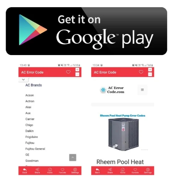
*If you can’t find the code you’re looking for on our site, please let us know, and we’ll update our database as soon as possible.