Диагностика проблем с помощью журналов
Эта страница призвана показать вам , как диагностировать топ-5 наиболее распространненых проблем, влияющих на конфигурация APM:Copter в частности,
но в некой стемени на конфигурацию APM:Plane и APM:Rover так же. Если вы еще не знакомы с основами журналов телеметрии
и журналов APM то рекомендуется ознакомиться с этими страницами, что бы понять где хранятся эти данные и как
можно скачать и посмотреть эту информацию.
Механические повреждения
Общие механические повреждения включают повреждения моторов или регуляторов скорости ESC (включая сбой синхронизации ESC)
скольшение пропеллеров (проворачивание пропеллеров в следствии плохой затяжки) и тому подобное. Они появляются в журнале как внезапное расхождение в нужном угле
тангажа или крена против фактического угла аппарата (по крену и тангажу / Roll and Pitch). Эти расхождения наиболее ярко видны в журнале из бортовой памяи полетного контроллера APM
путем построения графика ATT сообщений: Roll-In против Roll и Pitch-In против Pitch и в меньшей степени NavYaw против Yaw
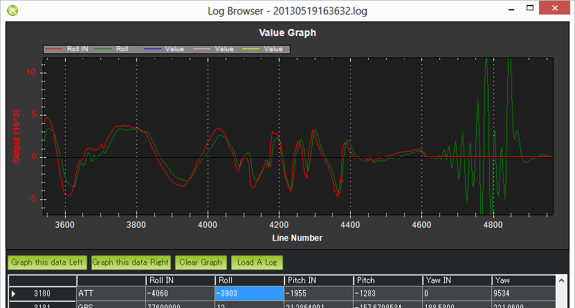
В приведеном выше примере фактическая Roll внимательно следует за нужным Roll-in для первой половины журнала, но потом расходиться.
Полетный контроллер apm хотел удерживать Roll на уровне (нулевой roll) но это было невозможно, скорее всего это означает механическое повреждение.
Это очень сильно отличается от программного сбоя в котором полетный контроллер ardupilot качался по Roll и по какой-то причине вдруг упал строго вниз , потому
что в таких случаях желаемый Roll будет так же сумащедшим как и текущий Roll и будет следовать за ним на графике.
Дополнительные замечания:
- Журналы tlog как правило труднее использовать в этом случае потому, что у нас есть nav_roll и nav_pitch, которые удерживают нужный крен и тангаж,
они обновляются только тогда , когда используется полетный режим RTL, Loiter или AUTO. - В прошивке ArduCopter 3.1 и выше Roll-In и Pitch-In удерживают только нужный крен и тангаж во время стабилизации.
А в режиме автопилота вы должны смотреть на NTUN сообщения: DRol и DPit.
Вибрации
Сильная вибрация у конфигурации ArduCopter вызывают у акселерометра, базирующемуся на высоте и горизонтальной позиции , заставляют дрейфовать далеко от реальности,
что приводит к проблемам с удержанием высоты (обычно летит в небо) или режиме Loiter (дрейфует)
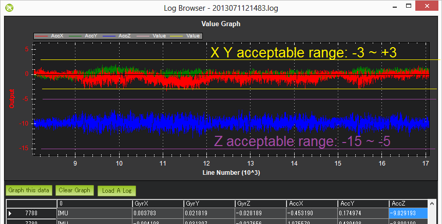
Вибрации лучше изучаь путем построение графиков из IMU сообщений с бортовой памяти APM по значениям AccX, AccY and AccZ.
Значения AccX, AccY (в первую очередь используются для горизонтального управления положением) должны быть между -3 и 3 м/с/с.
Значения акселерометра изменятся моментально, когда квадрокоптер движеся вверх или вниз, поэтому лучше достать данные порциями, когда полет
квадрокоптера был стационарным, хотя даже в движении можно увидеть уровень вибрации сравнивая разницу между верхней и нижней частью «травы».
иногда график прямолинеен, но когда «травинки» скачут, то скорее всего это проблема вибрации.
Ниже на графике указаны допустимые уровни вибрации.
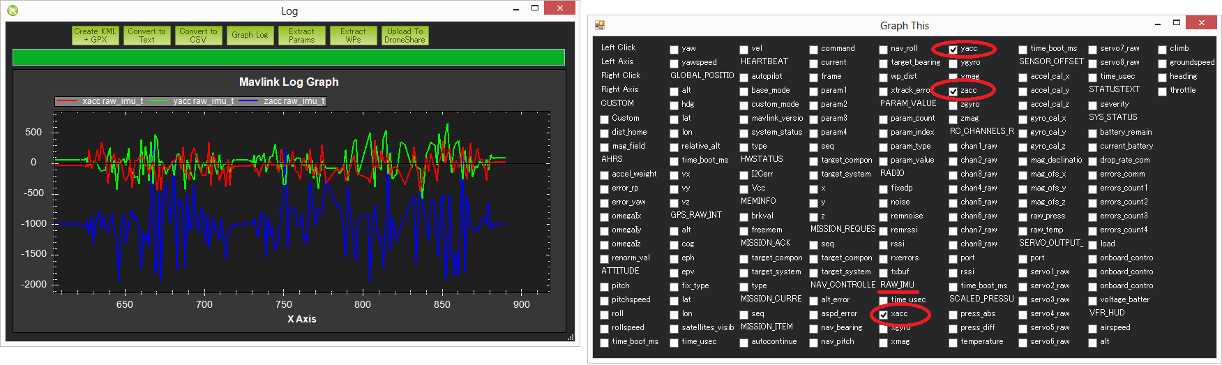
Журналы TLOG RAW_IMU xacc, yacc and zacc можно использоватль, но их обновление происходит значительно медленее (как правило менее 10Гц)
чем журнал из полетного контроллера ardupilot (50Гц) из-за этого становиться труднее понять являются ли изменения в акселерометре
квадрокоптера перемещением или вибрацией
Если вы используете tlog шкалу в milli-gs то приемлемый диапазон для xacc и yacc от -300 до +300 и для zacc от -500 до -1500.
Обратите внимание, что на рисунке значения ниже этого диапазона указывают на проблему вибрации , хотя этот пилот не жаловался
на режимы AltHold и Loiter — это более вероятно , что квадрокоптер был не в стабильном наведении и частота обновления была низкой.
Вмешательства в работу компаса
Помехи от распределительной платы PDB, двигаелей, батареи , регуляторов моторов и других электрических устройств рядом с APM могут скинуть направление
по компасу, который может привести к кругу ( известно как «туалетный боулинг»)
Помехи от распределительной платы, двигателей, батареи, регуляторов скорости ESC и других электрических
устройств квадрокоптера рядом с полетным контроллером ArduPilot Mega могут влиять на головное
направление компаса, который может привести к «круговым полетам» ( так называемы туалетное смытие)
или даже полет в неправильном направлении.
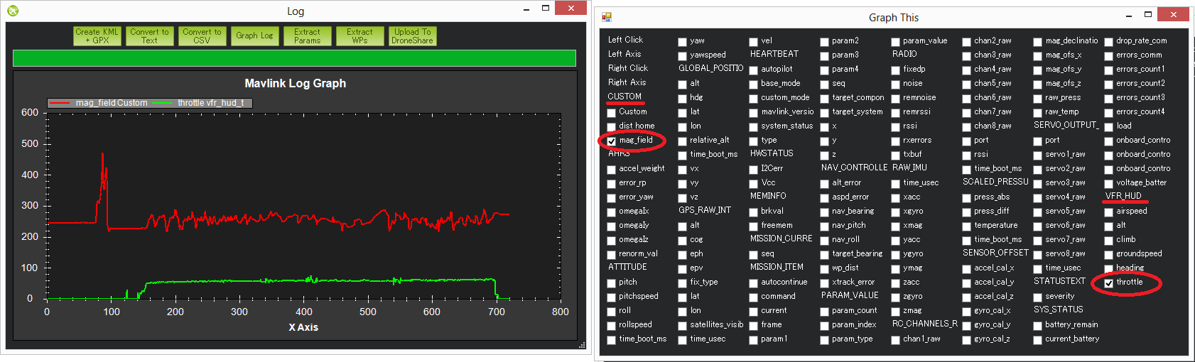
Графическое значение mag_field в TLOG (находиться пот «CUSTOM») и дроссель (находиться под VFR_HUD)
является самым простым способом, что бы увидеть количество помех.
В графе ниже показано приемлимое количество помех. Вы можете увидеть как колеблится
mag_field когда дросель газа поднят, но только движение вокруг на 10-20%. Ниже 30%
движение является приемлемым. В диапазоне 30-60% находится серая зона,
где он может быть в порядке (у некоторых пилотов) и очень плохом диапазоне
магнитных помех будет отображаться скачками более 60%, когда дроссель поднят.
Примечания:
- Длина mag_field может быть от 120 ~ 550 в зависимости от того,
где и каком месте находиться квадрокоптер, но обычно оно составляет около 330 . - Магнитные помехи в виде процента от общего магнитного поля также отображаются в конце
процедуры настройки compassmot. - Бортовой журнал полетного контроллера Ardupilot mega содержит «сырые» данные
компаса x, y и z осей (называемые MagX, MagY, MagZ), которые эквивалентны
RAW_IMU xmag, ymag и zmag полям в TLOG. Длину поля можно вычислить загрузив
из бортового журнала данные в Excel фильтруя по сообщениям COMPASS,
а затем расчитать магнитное поле по формуле mag_field =
SQRT (MagX^2, MagY^2, MagZ^2). Обратите внимание, что журналирование
сообщения сомпаса не включены по умолчанию, потому, что он работает
на частоте 50Гц и влияет немного на производительность процессора. - Еще одни параметры которые нужно проверить, должны быть
в пределах между — 150 и +150. Они находятся в TLOG группе SENSOR_OFFSET
в качестве mag_ofs_x, mag_ofs_y, mag_ofs_z и в журнале полетного контроллера
сообщения COMPASS в качестве OfsX, OfxY, OfxZ. Так же можно увидеть в параметрах как
COMPASS_OFS_X, COMPASS_OFS_Y , COMPASS_OFS_Z. - Изображение выше показывает короткий пик в начале графика,
но это может быть проигнорировано потому, что это перед поднятием
дроссельной заслонки. Это вероятно просто подключение других электрических
устройств.
GPS глюки
Находясь в режимах автопилота (Loiter, RTL, AUTO) ошибки позиционирования от GPS могут привести
ArduCopter к неправильному местоположению и спровоцировать к агресивному полету исправления позиции.
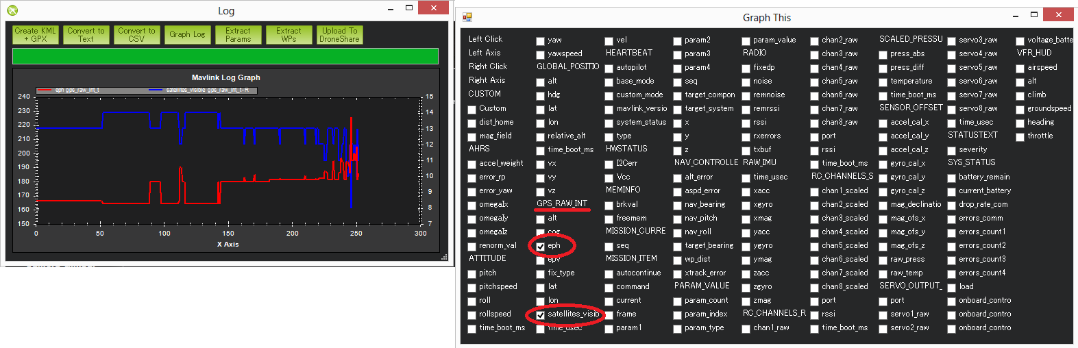
Эти «глюки» появляюстся в обоих журналах : TLOG и журнале полетного контроллера ardupilot mega apm
как уменьшение числа видимых спутников и увеличение HDOP.
Если с помощью графика TLOGs вы можете сделать это путем построения графика группы «GPS_RAW_IT»
значений «eph» и «satellites_visible». Значения HDOP 1,5 (отображаются на экране 150) или ниже
— это очень хорошо. Выше 2,0 (т.е. 200) указывает на плохое значение позиции. Количество спутников,
ниже 9 так же плохо. Существенное изменение этих двух значений часто сопровождает изменение позиции GPS.
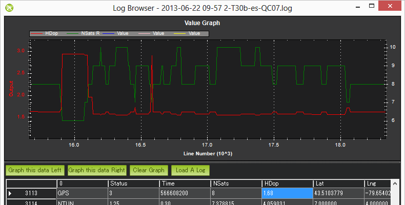
В журнале полетного контроллера ardupilot mega apm сообщений GPS вы найдёте HDOP и столбцы NSats.
Примечание! Значения HDOP находятся в правельных единицах измерения в журнале полетного контроллера
(т.е. не 100 с лишним , как в tlogs).
В прошивке ArduCopter 3.1 и выже присуствует алгоритм обнаружения «GPS глюков»
для их игнорирования.
Проблемы системы питания (Угасание и прочие)
Внедрение модуля питания стало гораздо проще для людей,
что бы обеспечить надежное энергоснабжение квадрокоптера
на полетном контроллере APM. Это привело к массовому сокращению числа «пониженного» питания,
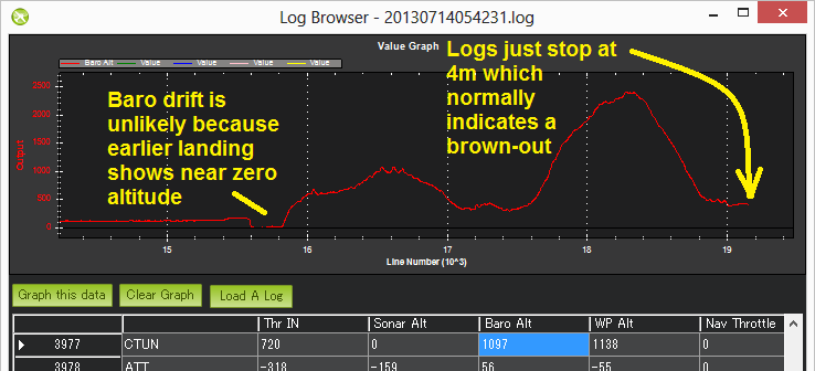
но они все еще имеют место быть. Как правило они могут присуствовать в журналах и
внезапно заканчиваться, когда квадрокоптер все еще находиться в
воздухе (например барометр или инерциальная навигация высоты по прежнему
сообщает о высоте выше нуля).
Используйте графики:
- Журнал полетного контроллера, CTUN сообщения, значение Baro-Alt
- Журнал полетного контроллера, GPS сообщения, значения RelAlt (комбинированое значение акселерометра + барометра)
- Журнал TLOG значение VHR_HUD alt (комбинированое значение акселерометра + барометра)
- Журнал TLOG значение GLOBAL_POSITION relative_alt
Изменения в напряжении на борту полетного контроллера может быть признаком проблемы питания.
Нормальные изменения в пределах от 0.10 до 0.15 вольт. Большие изменения могут быть признаком того,
что другие устройства питающиеся на общей фазе APM вызывают «рябь» в блоке питания,
что может привезти к «понижению» питания или другому странному поведению.
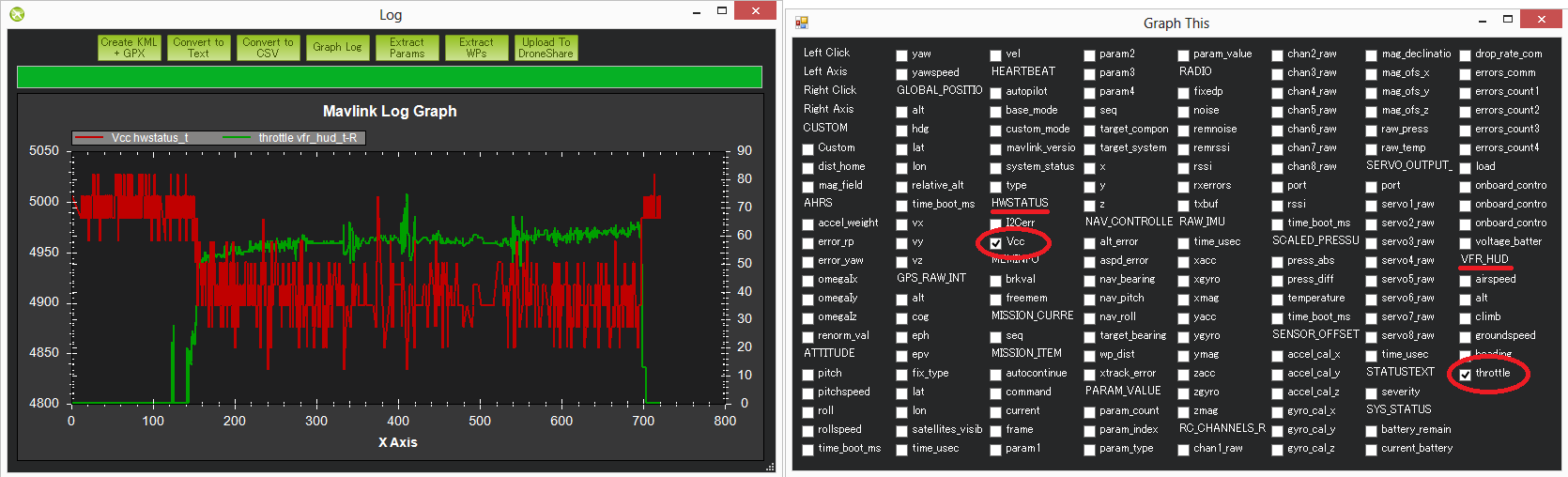
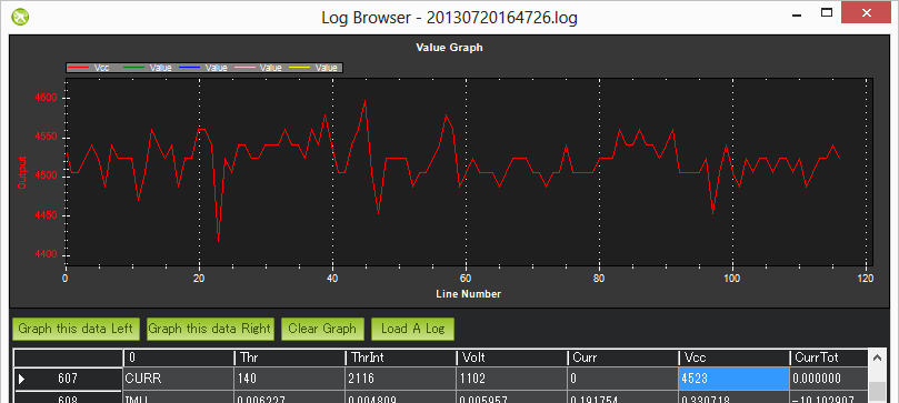
Бортовое напряжение платы полетного контроллера можно отобразить на графиках:
- Журнале полетного контроллера в сообщениях CURRENT значение VCC
- Журнале телеметрии (tlog) группы HWSTATUS’s значение Vcc
На изображение ниже показано просадка по напряжению на полетном контроллере на 0.15 вольт,
когда подается дроссельный газ. Как правило это не очень хорошая вещь, но из-за
того, что это только 0.15 вольт это наверное еще хорошо. Второй график ниже
(из журнала полетного контроллера другого пилота) показывает более
сильное изменение напряжение, но и как характерно пределах 0.15 вольт.
Неожиданные ошибки включая failsafes (защита отказа)
Когда происходит неожиданное поведение у полетного контроллера (особенно, когда пилот жалуется,
что квадрокоптер не ответил на команды с радиоаппаратуры) это часто является одной из причины
срабатывания failsafe (защита отказа). Есть 5 защит от отказов, которые могут быть активированны:
защита газа, gps защита, защита наземной станции, защита отказа батареи и «виртуальный забор».
Самый простой способ найти срабатывание защиты посмотреть журнал полетного контроллера фильтруя
по сообщениям ERR первый столбец.
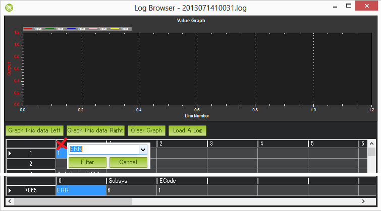
В Subsys (подсистеме) есть область, которая генерирует вызвающую ошибку и ECODE (известная как «код ошибки»)
— это говорит нам, что ошибка была специальная. Ограниченное количество подсистем и кодов ошибок
можно найти в исходных кодах конфигурации ArduCopter файла defines.h.
Sub Systems / Error Codes
- 1: Main (never used)
- 2: Radio
- ECode 1: “Late Frame” which means the APM’s onboard ppm encoder did not provide an update for at least 2 seconds
- ECode 0: error resolved which means the ppm encoder started providing data again
- 3: Compass
- ECode 1: the compass failed to initialise (likely a hardware issue)
- ECode 2: failure while trying to read a single value from the compass (probably a hardware issue)
- ECode 0: above errors resolved
- 4: Optical flow
- Ecode 1: failed to initialise (likely a hardware issue)
- 5: Throttle failsafe
- ECode 1: throttle dropped below FS_THR_VALUE meaning likely loss of contact between RX/TX
- ECode 0: above error resolve meaning RX/TX contact likely restored
- 6: Battery failsafe
- ECode 1: battery voltage dropped below LOW_VOLT or total battery capacity used exceeded BATT_CAPACITY
- 7: GPS failsafe
- ECode 1: GPS lock lost for at least 5 seconds
- ECode 0: GPS lock restored
- 8: GCS (Ground station) failsafe
- ECode 1: updates from ground station joystick lost for at least 5 seconds
- ECode 0: updates from ground station restored
- 9: Fence
- ECode 1: altitude fence breached
- ECode 2: circular fence breached
- ECode 3: both altitude and circular fences breached
- ECode 0: vehicle is back within the fences
- 10: Flight Mode
- ECode 0 ~ 10: the vehicle was unable to enter the desired flight mode
- (0=Stabilize, 1=Acro, 2=AltHold, 3=Auto, 4=Guided, 5=Loiter, 6=RTL, 7=Circle, 8=Position, 9=Land, 10=OF_Loiter)
- 11: GPS
- ECode 2: GPS Glitch
- ECode 0: GPS Glitch cleared
- 12: Crash Check
- ECode 1: Crash detected
каталог
- каталог
- резюме
- Первое: введение в предпродажную подготовку
- Второе: уведомление об ошибке перед включением
- 1. Подготовка перед использованием
- Причины невозможности разблокировки с помощью анализа информации Pre-Arm:
- 2. Причины сбоя разблокировки
- 3. Причина сбоя разблокировки (переведите ее на официальный сайт)
- # 1 проверка безопасности перед разблокировкой
- # 2 использовать GCS, чтобы определить причину ошибки предподключения
- # 3 сообщение об ошибке
-
-
- Отказ RC (то есть отказ передатчика / приемника):
- (2) Отказ барометра:
- (3) Отказ компаса:
- (4) Ошибки, связанные с GPS:
- (5) Инспекция INS (т.е. ускорение и гироскопическая проверка):
- (6) Проверка источника питания:
- (7) Проверка параметров:
-
-
- 1. Подготовка перед использованием
- Третье: анализ кода ошибки перед постановкой на охрану
- Инициализация обнаружения 1.Pre-Arm
- Обновление обнаружения 2.Pre-Arm
- Анализ функции 3.Pre-Arm
-
- 1. Проверка разблокировки барометра
- Проверка дистанционного управления 2.Remote
- 3. Проверка разблокировки компаса
- Проверка разблокировки 4.GPS
- Проверка разблокировки 5.Fence
- Проверка разблокировки данных навигации 6.Inertia
- 7. Проверка разблокировки напряжения
- Проверка блокировки 8.Log
- Проверка разблокировки 9.Parameter
- 10.Моторная разблокировка
- 11. Проверка разблокировки дроссельной заслонки
-
- Четвертое: как Pre-Arm отображает наземную станцию и выдает сообщения об ошибках
резюме
В этом разделе в основном анализируется процедура проверки безопасности перед подготовкой для многороторной части ardupilot. Добро пожаловать, чтобы критиковать и исправлять! ! !
Первое: введение в предпродажную подготовку
Ardupilot: Многофункциональное встроенное программное обеспечение ArduCopter имеет очень полный набор напоминаний о проверке безопасности перед подготовкой. Он проверит ваш самолет на наличие большого количества проблем, включая различные ошибки калибровки, а также наличие повреждений датчика. Конечно, механизм проверки разблокировки На 100% надежно, вы можете отключить его с помощью Arming-check в полном списке параметров.
Обратите внимание, что:
Поскольку версия микропрограммы управления полетом постоянно обновляется, некоторые сообщения об ошибках могут изменяться, могут не соответствовать данной статье или не описаны в этой статье, все нормально. Вы можете искать, используя свою собственную поисковую систему
Второе: уведомление об ошибке перед включением
1. Подготовка перед использованием
Используйте наземную станцию GCS (Missionplanner) для просмотра сообщений об ошибках предподключения
вМигающий желтый свет, Пользователи не смогут разблокировать, а при разблокировкеЗуммер также будет звучать дважды, На этом этапе вы должны подключиться к наземной станции, чтобы исключить проблему, которую вы не можете разблокировать и летать.Датчик не откалиброван Или появилсяБеглая защита、Неверная настройка низкого напряженияИ так далее,Следующее подробно проанализирует каждую ошибку:
Причины невозможности разблокировки с помощью анализа информации Pre-Arm:
(1) Приемник дистанционного управления был подключен к плате управления полетом, иСнять винт и аккумулятор(Это очень важно !!! Безопасность прежде всего)
(2) Подключите к наземной станции через USB или цифровую передачу (Mission Planner)
(3) Включите пульт дистанционного управления и попытайтесь разблокировать; каналы разблокировки: нижний газ (3 канала), крайний правый рычаг (4 канала) (Это метод разблокировки по умолчанию для apm)
(4) В этот момент он должен быть виден в окне наземной станцииОшибка предплечья красным, Если подсказка отсутствует, канал разблокировки неправильный. В результате контроллер полета не может обнаружить вашу операцию разблокировки. Вы также можете щелкнуть операцию разблокировки в строке состояния интерфейса данных полета наземной станции.
2. Причины сбоя разблокировки
(1) Часто задаваемые вопросы

(2) Часто задаваемые вопросы электронного компаса

(3) общие неисправности GPS


(4) Инспекция INS (например, акселерометр и гироскоп)


Приведенные выше ссылки в основном принадлежат Lexun:Лей Сюнь анализ предплечья
Более важная информация — официальный сайт:Официальный сайт Ardupilot Pre-Arm анализ, Лей Сюнь чисто перевод
3. Причина сбоя разблокировки (переведите ее на официальный сайт)
# 1 проверка безопасности перед разблокировкой
(Pre-Arm Safety Check)
Микропрограммное обеспечение беспилотного летательного аппарата включает в себя полный набор процедур проверки разблокировки безопасности, чтобы предотвратить проблемы с безопасностью после того, как беспилотник разблокирован из-за некоторых сбоев, если возникнут какие-либо проблемы до того, как дрон взлетит, в том числе датчик не откалиброван , Условия ошибки, такие как неправильная конфигурация или данные датчика, не позволят дрону взлететь. Эти проверки помогают предотвратить сбой и полет дронов. Но при необходимости, конечно, мы можем отключить настройку проверки безопасности через настройки параметров, но я лично считаю, что она должна быть включена. (Личное понимание смешано в переводе)
# 2 использовать GCS, чтобы определить причину ошибки предподключения
(Recognising which Pre-Arm Check has failed using the GCS)
Пилот должен отметить, что если проверка безопасности не удалась во время разблокировки, пилот не сможет разблокировать дрон, и управление полетом будет сопровождаться мигающим желтым светодиодом. Следовательно, проверка безопасности должна выполняться точно:
1. Подключите данные контроллера полета к наземной станции с помощью USB-кабеля для передачи данных или модуля передачи данных.
2. Убедитесь, что GCS подключен к дрону (т. е. в плоскости полета нажмите кнопку «подключения» в правом верхнем углу).
3. Включите передатчик радиоуправления и попытайтесь разблокировать беспилотник (в обычных процедурах дроссель опускается вниз и поворачивается вправо).
4. Причина неудачной проверки разблокировки будет отображаться красным цветом в окне HUD. Мы можем проанализировать причину ошибки через причину ошибки.
# 3 сообщение об ошибке
(Failure messages)
Отказ RC (то есть отказ передатчика / приемника):
(1)RC not calibrated: Радио калибровка не была выполнена. RC3_MIN и RC3_MAX должны быть изменены со своих значений по умолчанию (1100 и 1900), а для каналов с 1 по 4 значение MIN должно быть 1300 или меньше, а значение MAX должно быть 1700 или выше.
(2) Отказ барометра:
Baro не здоров: BARO вреден для здоровья, а датчик барометра сообщает, что он вреден для здоровья, что обычно является признаком аппаратного сбоя.
Альтернативное расхождение: (разница высот), разница между высотой барометра и высотой инерциальной навигации (т. е. барометр + акселерометр) превышает 2 метра. Это сообщение обычно недолговечное и может появиться, когда контроллер полета впервые подключен или если он получает сильный удар (например, внезапное снижение). Если неясно, акселерометр может потребоваться откалибровать, или может быть аппаратная проблема с барометром.
(3) Отказ компаса:
Compass not healthy :Нездоровый компас: датчик компаса сообщает, что он вреден для здоровья, что является признаком аппаратного сбоя.
Compass not calibrated :Компас не был откалиброван. Параметры COMPASS_OFS_X, Y, Z равны нулю, или число или тип подключенных компасов изменились с момента последней калибровки компаса.
Compass offsets too high :Длина смещения основного компаса (т.е. SqRT (x ^ 2 + y ^ 2 + z ^ 2)) превышает 500. Это может быть вызвано тем, что металлические предметы находятся слишком близко к компасу. Если вы используете только внутренний компас (не рекомендуется), это может быть просто металл в пластине, который вызывает большие смещения, что может и не быть проблемой, и в этом случае вы можете отключить проверку компаса.
Check mag field : Чувствительное магнитное поле в этой области составляет 35% или меньше, чем ожидалось. Ожидаемая длина составляет 530, поэтому> 874 или <185. Напряженность магнитного поля варьируется по всему миру, но эти широкие ограничения означают, что калибровка компаса, скорее всего, не сможет рассчитать хорошее смещение и должна быть повторена.
Compasses inconsistent :Направление компаса противоречиво: внутренний компас и внешний компас указывают в разных направлениях (более 45 градусов). Обычно это вызвано неправильной настройкой внешнего направления компаса (т. Е. География, параметры направления компаса).
(4) Ошибки, связанные с GPS:
GPS Glitch :
Индикатор GPS мигает: индикатор GPS мигает, и дрон находится в режиме полета, в котором требуется режим GPS (т. е. режим ожидания, PosHold и т. д.) и / или включен круговой забор.
Need 3D Fix : У GPS нет трехмерного решения, и дрон находится в режиме GPS и / или режиме полета с включенным круговым забором.
Bad Velocity :Скорость беспилотника (по данным инерциальной навигационной системы) выше 50 см / с. Проблемы, которые могут вызвать это, включают фактическое движение транспортного средства или снижение, плохую калибровку акселерометра и обновления GPS ниже ожидаемых 5 Гц.
Высокая GPS HDOP: ** Значение HDPP (значение точности позиционирования) GPS превышает 2,0, и автомобиль находится в режиме позиционирования GPS и / или в режиме полета с круговым забором. Мы можем просто исправить это, подождав несколько минут, переместившись в место с лучшим обзором неба или проверив, что источник помех GPS (то есть устройство FPV) сместился дальше от GPS. Или вы можете добавить ** GPS_HDOP_GOOD, изменивПараметр равен 2,2 или 2,5, чтобы ослабить проверку. В худшем случае, пилоты могут отключить заборы и взлеты в режимах, которые не требуют GPS (то есть, Стабильный, AltHold) и переключиться на Loiter после разблокировки, но это не рекомендуется. (Это слишком опасно. Перед взлетом обязательно выполните GPS-позиционирование. В настоящее время можно выбрать три режима.)
** Примечание: ** GPS HDOP можно легко просмотреть с помощью быстрой вкладки планировщика миссии, как показано ниже.

(5) Инспекция INS (т.е. ускорение и гироскопическая проверка):
** INS не откалиброван: ** INS не откалиброван: смещение некоторых или всех акселерометров равно нулю. Акселерометр необходимо откалибровать.
Accels not healthy: ACCEL вреден для здоровья: отчет по акселерометру вреден для здоровья, что может быть связано с аппаратными проблемами. Это также может произойти сразу после обновления прошивки до перезапуска платы.
Accels inconsistent: Несогласованность ускорения: акселерометр сообщает, что текущее ускорение отличается не менее чем на 1 м / с / с. Акселерометр необходимо откалибровать, иначе возникла аппаратная проблема.
Gyros not healthy: Гироскоп вреден для здоровья: гироскоп сообщает, что он вреден для здоровья, что может быть аппаратной проблемой. Это также может произойти сразу после обновления прошивки до перезапуска платы.
Gyro cal failed: Ошибка калибровки гироскопа: калибровка гироскопа не смогла зафиксировать смещение. Это часто перемещается дронами во время калибровки гироскопа (Когда мигают красные и синие огни) В этом случае отсоедините аккумулятор и вставьте его снова, соблюдая осторожность, чтобы не сдвинуть дрон, что может решить проблему. Отказ оборудования датчика (например, пики) также может быть причиной этого сбоя.
Gyros inconsistent: Гироскопы несовместимы: скорости вращения транспортного средства, сообщаемые двумя гироскопами, отличаются более чем на 20 дг / с. Это может быть вызвано неисправностью оборудования или плохо откалиброванным гироскопом.
(6) Проверка источника питания:
Board Voltage checks:Проверьте напряжение платы источника питания: внутреннее напряжение печатной платы ниже 4,3 вольт или выше 5,8 вольт.
При питании от USB-кабеля (то есть на рабочем месте) это может быть связано с тем, что настольный компьютер не может обеспечить достаточный ток для контроллера полета, попробуйте заменить USB-кабель.
Если он питается от батареи, это серьезная проблема, и перед полетом необходимо тщательно проверить систему питания (например, модуль питания, батарею и т. д.).
(7) Проверка параметров:
Ch7&Ch8 Opt cannot be same:
Параметры Ch7 и Ch8 не могут быть одинаковыми: переключатель доступности установлен на одну и ту же опцию, которая недопустима, поскольку может вызвать путаницу.
Check FS_THR_VALUE: Отказоустойчивое значение ШИМ пульта дистанционного управления установлено слишком близко к минимальному значению канала дроссельной заслонки (например, CH3).
Check ANGLE_MAX:Параметр AGLE_MAX, управляющий максимальным наклоном дрона, устанавливается ниже 10 градусов (т.е. 1000) или выше 80 градусов (т.е. 8000).
** ACRO_BAL_ROLL / PITCH: ** Параметр ACRO_BAL_ROLL выше, чем стабильный бросок P, и / или параметр ACRO_BAL_PITCH выше значения P стабильного шага. Это может привести к тому, что оператор не сможет контролировать угол наклона в режиме ACRO, поскольку стабильность тренажера Acro будет превышать входные данные оператора.
Третье: анализ кода ошибки перед постановкой на охрану
Инициализация обнаружения 1.Pre-Arm

void Copter::init_ardupilot()
{
     arming.pre_arm_rc_checks(true);
    if (ap.pre_arm_rc_check) // Выход двигателя можно включить только в том случае, если пульт дистанционного управления проверил его.
    {
        enable_motor_output(); // Включить вывод двигателя
    }
}
(1)arming.pre_arm_rc_checks(true);
Выполняет предварительные проверки, связанные с GPS, и возвращает TRUE, если прошло
void AP_Arming_Copter::pre_arm_rc_checks(const bool display_failure)
{
    // exit immediately if we've already successfully performed the pre-arm rc check
    if (copter.ap.pre_arm_rc_check) {
        return;
    }

    // set rc-checks to success if RC checks are disabled
    if ((checks_to_perform != ARMING_CHECK_ALL) && !(checks_to_perform & ARMING_CHECK_RC)) {
        set_pre_arm_rc_check(true);
        return;
    }

    const RC_Channel *channels[] =
    {
        copter.channel_roll,
        copter.channel_pitch,
        copter.channel_throttle,
        copter.channel_yaw
    };
    const char *channel_names[] = { "Roll", "Pitch", "Throttle", "Yaw" };

    for (uint8_t i=0; i<ARRAY_SIZE(channels);i++)
    {
        const RC_Channel *channel = channels[i];
        const char *channel_name = channel_names[i];
        // check if radio has been calibrated
        if (!channel->min_max_configured()) {
            if (display_failure) {
                copter.gcs_send_text_fmt(MAV_SEVERITY_CRITICAL,"PreArm: RC %s not configured", channel_name);
            }
            return;
        }
        if (channel->get_radio_min() > 1300) {
            if (display_failure) {
                copter.gcs_send_text_fmt(MAV_SEVERITY_CRITICAL,"PreArm: %s radio min too high", channel_name);
            }
            return;
        }
        if (channel->get_radio_max() < 1700) {
            if (display_failure) {
                copter.gcs_send_text_fmt(MAV_SEVERITY_CRITICAL,"PreArm: %s radio max too low", channel_name);
            }
            return;
        }
        if (i == 2) {
            // skip checking trim for throttle as older code did not check it
            continue;
        }
        if (channel->get_radio_trim() < channel->get_radio_min()) {
            if (display_failure) {
                copter.gcs_send_text_fmt(MAV_SEVERITY_CRITICAL,"PreArm: %s radio trim below min", channel_name);
            }
            return;
        }
        if (channel->get_radio_trim() > channel->get_radio_max()) {
            if (display_failure) {
                copter.gcs_send_text_fmt(MAV_SEVERITY_CRITICAL,"PreArm: %s radio trim above max", channel_name);
            }
            return;
        }
    }

    // if we've gotten this far rc is ok
    set_pre_arm_rc_check(true);
}
(2) enable_motor_output (); // Включить выход двигателя. Когда ap.pre_arm_rc_check = 1, включите его, в противном случае — нет.
void Copter::enable_motor_output()
{
    // enable motors
    motors->enable();
    motors->output_min();
}
Обновление обнаружения 2.Pre-Arm
(1) Функция первого шага
SCHED_TASK(one_hz_loop, 1, 100), // Выполнить проверку разблокировки(2) функция второго шага
void Copter::one_hz_loop()
{

   arming.update();
}
(3) функция третьего шага
Перед разблокировкой выполните проверку, рабочий цикл равен 1 с, а частота равна 1 Гц.
void AP_Arming_Copter::update(void)
{
    // Выполняем проверку постановки на охрану и отображаем сбои каждые 30 секунд ---- выполняем проверку перед постановкой на охрану и сбои индикации каждые 30 секунд
    static uint8_t pre_arm_display_counter = PREARM_DISPLAY_PERIOD/2; //# define PREARM_DISPLAY_PERIOD 30
    pre_arm_display_counter++;
    bool display_fail = false;
    if (pre_arm_display_counter >= PREARM_DISPLAY_PERIOD) // до 30 с
    {
        display_fail = true;
        pre_arm_display_counter = 0;
    }

    if (pre_arm_checks(display_fail)) // Ключевой анализ
    {
        set_pre_arm_check(true);
    }
}
Функция анализа pre_arm_checks (display_fail)
bool AP_Arming_Copter::pre_arm_checks(bool display_failure)
{
    // Выход немедленно, если рука разблокирована
    if (copter.motors->armed())
    {
        return true;
    }

    // check if motor interlock and Emergency Stop aux switches are used
    // at the same time.  This cannot be allowed.
    // Проверьте, используются ли блокировка двигателя и вспомогательный выключатель аварийного останова одновременно. Это не разрешено
    if (copter.check_if_auxsw_mode_used(AUXSW_MOTOR_INTERLOCK) && copter.check_if_auxsw_mode_used(AUXSW_MOTOR_ESTOP)){
        if (display_failure) {
            gcs_send_text(MAV_SEVERITY_CRITICAL,"PreArm: Interlock/E-Stop Conflict");
        }
        return false;
    }

    // Проверьте, используется ли переключатель блокировки двигателя ---- проверьте, используется ли вспомогательный переключатель блокировки двигателя
    // если это так, переключатель должен быть в отключенном положении, чтобы поставить
    // В противном случае выйдите немедленно. Эта проверка повторяется, потому что статус может измениться в любое время. в противном случае немедленно завершите работу. Эта проверка должна быть повторена, так как состояние может измениться в любое время.
    if (copter.ap.using_interlock && copter.ap.motor_interlock_switch)
    {
        if (display_failure)
        {
            gcs_send_text(MAV_SEVERITY_CRITICAL,"PreArm: Motor Interlock Enabled");
        }
        return false;
    }

    // Если мы успешно выполнили предварительную проверку, немедленно завершите работу - выйдите немедленно, если мы уже успешно выполнили проверку перед постановкой на охрану
    if (copter.ap.pre_arm_check)
    {
        // Запускаем проверку GPS, потому что результаты могут измениться и повлиять на цвет светодиода. Дисплею не нужно отказывать, потому что, если пилот попробует ARMARCHECK, он выполнит операцию.
        // run gps checks because results may change and affect LED colour
        // no need to display failures because arm_checks will do that if the pilot tries to arm
        pre_arm_gps_checks(false);
        return true;
    }

    // Возвращаем 1, если проверка разблокировки не включена ----- успешно, если предварительная проверка отключена
    if (checks_to_perform == ARMING_CHECK_NONE)
    {
        set_pre_arm_check(true);
        set_pre_arm_rc_check(true);
        return true;
    }

 return barometer_checks(display_failure)         // Функция проверки барометра
        & rc_calibration_checks(display_failure)  // Функция обнаружения дистанционного управления
        & compass_checks(display_failure)         // Проверяем компас
        & gps_checks(display_failure)             // проверяем gps
        & fence_checks(display_failure)           // проверить забор
        & ins_checks(display_failure)             // Проверка данных инерциальной навигации
        & board_voltage_checks(display_failure)   // Проверка платы напряжения
        & logging_checks(display_failure)         // проверка журнала
        & parameter_checks(display_failure)       // Проверка параметров
        & motor_checks(display_failure)           // Проверьте мотор
        & pilot_throttle_checks(display_failure); // Проверка дроссельной заслонки
}
Функция анализа set_pre_arm_check (true)
void AP_Arming_Copter::set_pre_arm_check(bool b)
{
    if(copter.ap.pre_arm_check != b)
    {
        copter.ap.pre_arm_check = b;
        AP_Notify::flags.pre_arm_check = b;
    }
}
Анализ функции 3.Pre-Arm
1. Проверка разблокировки барометра
bool AP_Arming_Copter::barometer_checks(bool display_failure)
{
    // Проверка барометра ------ проверка Баро
    if ((checks_to_perform == ARMING_CHECK_ALL) || (checks_to_perform & ARMING_CHECK_BARO))
    {
        // Здоров ли барометр ------ проверка состояния барометра
        if(!barometer.healthy())
        {
            if (display_failure)
            {
                gcs_send_text(MAV_SEVERITY_CRITICAL,"PreArm: Barometer not healthy"); // Барометр ненормальный
            }
            return false;
        }
        // Check baro & inav alt are within 1m if EKF is operating in an absolute position mode.
        // Do not check if intending to operate in a ground relative height mode as EKF will output a ground relative height
        // that may differ from the baro height due to baro drift.
        // Если EKF работает в режиме контроля абсолютного положения, проверьте, находится ли разница между BARO и IANV ALT в пределах 1M.
        // Не проверяйте, намереваетесь ли вы работать в режиме относительной высоты над землей, потому что выход EKF может быть на другой земле относительно высоты давления воздуха из-за дрейфа давления воздуха.
        nav_filter_status filt_status = _inav.get_filter_status();
        bool using_baro_ref = (!filt_status.flags.pred_horiz_pos_rel && filt_status.flags.pred_horiz_pos_abs);
        if (using_baro_ref)
        {
            if (fabsf(_inav.get_altitude() - copter.baro_alt) > PREARM_MAX_ALT_DISPARITY_CM) // Получает ли инерциальная навигация высоту, превышающую высоту барометра на 1 м?
            {
                if (display_failure)
                {
                    gcs_send_text(MAV_SEVERITY_CRITICAL,"PreArm: Altitude disparity"); // Ошибка слишком большой разницы
                }
                return false; // возвращаем 0, обнаружение ошибки
            }
        }
    }
    return true; // Успех здесь
}
Проверка дистанционного управления 2.Remote
bool AP_Arming_Copter::rc_calibration_checks(bool display_failure)
{
    // Перед разблокировкой pre-arm rc проверяет предварительное условие
    pre_arm_rc_checks(display_failure);
    return copter.ap.pre_arm_rc_check;// Возврат в разблокированное состояние
}
Проанализируйте функцию: pre_arm_rc_checks (display_failure)
void AP_Arming_Copter::pre_arm_rc_checks(const bool display_failure)
{
    // Выйти немедленно, если мы успешно выполнили проверку RC предплечья ------ выйти немедленно, если мы уже успешно выполнили проверку предплечья rc
    if (copter.ap.pre_arm_rc_check) //copter.ap.pre_arm_rc_check=1, проверка прошла успешно
    {
        return;
    }

    // Если проверка RC отключена, установите успешную проверку RC ------------ установите успешную проверку rc, если проверки RC отключены
    if ((checks_to_perform != ARMING_CHECK_ALL) && !(checks_to_perform & ARMING_CHECK_RC)) // ARMING_CHECK_ALL = 0x01, битовый флаг ARMING_CHECK_ALL
    {
        set_pre_arm_rc_check(true);
        return;
    }

    const RC_Channel *channels[] =   // Устанавливаем отображение канала дистанционного управления, обычно устанавливаем roll-1, pitch-2, throttle-3, yaw-4
    {
        copter.channel_roll,
        copter.channel_pitch,
        copter.channel_throttle,
        copter.channel_yaw
    };
    const char *channel_names[] = { "Roll", "Pitch", "Throttle", "Yaw" };// Строковая константа

    for (uint8_t i=0; i<ARRAY_SIZE(channels);i++)    // Рассчитать количество байтов
    {
        const RC_Channel *channel = channels[i];     // Получить канал
        const char *channel_name = channel_names[i]; // Получить имя
        // Проверить, откалиброван ли пульт ДУ ------------------ Проверить, откалибровано ли радио
        if (!channel->min_max_configured()) // Получить канал-> min_max_configured () = 1, уже настроен, не вводить if, иначе вводить if, будет выдана ошибка
        {
            if (display_failure) //display_failure=1
            {
                copter.gcs_send_text_fmt(MAV_SEVERITY_CRITICAL,"PreArm: RC %s not configured", channel_name); // Отправить ошибку на наземную станцию
            }
            return;
        }
        if (channel->get_radio_min() > 1300) // Минимальное значение больше 1300, больше, чем сообщит об ошибке
        {
            if (display_failure)
            {
                copter.gcs_send_text_fmt(MAV_SEVERITY_CRITICAL,"PreArm: %s radio min too high", channel_name);
            }
            return;
        }
        if (channel->get_radio_max() < 1700) // Если максимальное значение меньше 1700, будет сообщено об ошибке, если оно меньше
        {
            if (display_failure)
            {
                copter.gcs_send_text_fmt(MAV_SEVERITY_CRITICAL,"PreArm: %s radio max too low", channel_name);
            }
            return;
        }
        if (i == 2)
        {
            // Когда старый код не проверен, пропустите проверку газа. ---- пропустить проверку триммера газа, так как старый код не проверял
            continue;
        }
        if (channel->get_radio_trim() < channel->get_radio_min()) // Данные дистанционного управления, меньше минимального значения, приглашение слишком низкое
        {
            if (display_failure)
            {
                copter.gcs_send_text_fmt(MAV_SEVERITY_CRITICAL,"PreArm: %s radio trim below min", channel_name);
            }
            return;
        }
        if (channel->get_radio_trim() > channel->get_radio_max()) // Данные дистанционного управления, больше максимума, приглашение слишком большое
        {
            if (display_failure)
            {
                copter.gcs_send_text_fmt(MAV_SEVERITY_CRITICAL,"PreArm: %s radio trim above max", channel_name);// Эта функция проанализирована позже
            }
            return;
        }
    }

    // Если код выполняется здесь, можно использовать RC. То есть, проверка качества пройдена, будьте уверены в использовании ------ если мы дошли до этого, то все в порядке
    set_pre_arm_rc_check(true);// Ключ должен быть установлен: copter.ap.pre_arm_rc_check = 1
}
Проанализируйте функцию: copter.gcs_send_text_fmt
При отправке отформатированных сообщений с низким приоритетом в GCS подходит только одно сообщение в очереди, поэтому, если несколько сообщений отправлено до того, как последнее поступит в последовательный буфер, старые сообщения будут потеряны. Эта функция находится в GCS_Mavlink.cpp. Эта функция сейчас не анализируется. Достаточно знать, что она отправляет ошибки на наземную станцию через mavlink. Она продолжит анализировать эту функцию, когда у нее будет время.
void Copter::gcs_send_text_fmt(MAV_SEVERITY severity, const char *fmt, ...)
{
    char str[MAVLINK_MSG_STATUSTEXT_FIELD_TEXT_LEN] {};
    va_list arg_list;
    va_start(arg_list, fmt);
    va_end(arg_list);
    hal.util->vsnprintf((char *)str, sizeof(str), fmt, arg_list);
    gcs().send_statustext(severity, 0xFF, str);
    notify.send_text(str);// Уведомить об отправке информации
}
3. Проверка разблокировки компаса
bool AP_Arming_Copter::compass_checks(bool display_failure)
{
    bool ret = AP_Arming::compass_checks(display_failure);// Проверка компаса для разблокировки

    if ((checks_to_perform == ARMING_CHECK_ALL) || (checks_to_perform & ARMING_CHECK_COMPASS))
    {
        // check compass offsets have been set.  AP_Arming only checks
        // this if learning is off; Copter *always* checks.
        // Убедитесь, что смещение компаса установлено. Только когда обучение закончено, проверка разблокировки только проверяет это, COPTER всегда проверяет.
        if (!_compass.configured())
        {
            if (display_failure)
            {
                gcs_send_text(MAV_SEVERITY_CRITICAL,"PreArm: Compass not calibrated"); // Отправить без калибровки
            }
            ret = false;
        }
    }

    return ret;
}
Функция анализа AP_Arming :: compass_checks (display_failure)
bool AP_Arming::compass_checks(bool report)
{
    if ((checks_to_perform) & ARMING_CHECK_ALL ||(checks_to_perform) & ARMING_CHECK_COMPASS) // начинать ли проверку компаса
    {

        if (!_compass.use_for_yaw())  // Если компас использует вычисление рыскания, возвращаем 1
        {
            // Если вы введете здесь, компас не включен ----- использование компаса отключено
            return true;
        }

        if (!_compass.healthy()) // Компас здоров? _Compass.healthy () = 1, он здоров, в противном случае он вреден для здоровья, он подскажет на наземной станции
        {
            if (report)
            {
                GCS_MAVLINK::send_statustext_all(MAV_SEVERITY_CRITICAL, "PreArm: Compass not healthy");// Ошибка подсказки
            }
            return false;
        }
        // Проверяем, что компас обучается или смещение установлено -------- проверяем, что компас включен или смещения установлены
        if (!_compass.learn_offsets_enabled() && !_compass.configured())
        {
            if (report)
            {
                GCS_MAVLINK::send_statustext_all(MAV_SEVERITY_CRITICAL, "PreArm: Compass not calibrated");
            }
            return false;
        }

        // проверка калибровки компаса ------ проверка калибровки компаса
        if (_compass.is_calibrating())
        {
            if (report)
            {
                GCS_MAVLINK::send_statustext_all(MAV_SEVERITY_CRITICAL, "Arm: Compass calibration running");
            }
            return false;
        }

        // Сообщаем, что компас проверки наземной станции откалиброван и его необходимо сбросить -------- проверить, откалиброван ли компас и требуется ли перезагрузка
        if (_compass.compass_cal_requires_reboot())
        {
            if (report)
            {
                GCS_MAVLINK::send_statustext_all(MAV_SEVERITY_CRITICAL, "PreArm: Compass calibrated requires reboot");
            }
            return false;
        }

        // проверка на необоснованные смещения компаса ------ проверка на необоснованные смещения компаса
        Vector3f offsets = _compass.get_offsets();
        if (offsets.length() > _compass.get_offsets_max())
        {
            if (report)
            {
                GCS_MAVLINK::send_statustext_all(MAV_SEVERITY_CRITICAL, "PreArm: Compass offsets too high");
            }
            return false;
        }

        // проверка на необоснованную длину поля MAG ------ проверка на необоснованную длину магнитного поля
        float mag_field = _compass.get_field().length();
        if (mag_field > AP_ARMING_COMPASS_MAGFIELD_MAX || mag_field < AP_ARMING_COMPASS_MAGFIELD_MIN)
        {
            if (report)
            {
                GCS_MAVLINK::send_statustext_all(MAV_SEVERITY_CRITICAL, "PreArm: Check mag field");
            }
            return false;
        }

        // Проверяем все точки компаса примерно в одном направлении
        if (!_compass.consistent())
        {
            if (report)
            {
                GCS_MAVLINK::send_statustext_all(MAV_SEVERITY_CRITICAL,"PreArm: Compasses inconsistent");
            }
            return false;
        }
    }

    return true;
}
Проверка разблокировки 4.GPS
bool AP_Arming_Copter::gps_checks(bool display_failure)
{
    // Проверка GPS ----- проверка GPS
    if (!pre_arm_gps_checks(display_failure))
    {
        return false;
    }
    return true;
}
Функция анализа pre_arm_gps_checks (display_failure)
bool AP_Arming_Copter::pre_arm_gps_checks(bool display_failure)
{
    //Всегда проверяйте, началась ли инерциальная навигация, и читайте данные ------ всегда проверяйте if inertial nav has started and is ready
    if (!ahrs.healthy()) //Данные не здоровы
    {
        if (display_failure)
        {
            gcs_send_text(MAV_SEVERITY_CRITICAL,"PreArm: Waiting for Nav Checks"); //Ожидание инерционной проверки навигации
        }
        return false;
    }

    //Проверьте, требует ли режим полета GPS ----- if flight mode requires GPS
    bool mode_requires_gps = copter.mode_requires_GPS(copter.control_mode);

    //Проверьте, требует ли забор GPS ------- проверка if fence requires GPS
    bool fence_requires_gps = false;
    #if AC_FENCE == ENABLED
    //Если круговые или полигональные заборы включены, нам нужен GPS. ---- if circular or polygon fence is enabled we need GPS
    fence_requires_gps = (copter.fence.get_enabled_fences() & (AC_FENCE_TYPE_CIRCLE | AC_FENCE_TYPE_POLYGON)) > 0;
    #endif

    //Если вам не нужен GPS, верните true ----- return true if GPS is not required
    if (!mode_requires_gps && !fence_requires_gps)
    {
        AP_Notify::flags.pre_arm_gps_check = true;
        return true;
    }

    //Убедитесь, что GPS хорошо ------- убедитесь, GPS is ok
    if (!copter.position_ok())
    {
        if (display_failure)
        {
            const char *reason = ahrs.prearm_failure_reason();
            if (reason)
            {
                GCS_MAVLINK::send_statustext_all(MAV_SEVERITY_CRITICAL, "PreArm: %s", reason);
            } else
            {
                if (!mode_requires_gps && fence_requires_gps)
                {
                    //Уточните пользователю, зачем ему GPS в режиме полета без GPS in non-GPS flight mode
                    gcs_send_text(MAV_SEVERITY_CRITICAL,"PreArm: Fence enabled, need 3D Fix");
                } else
                {
                    gcs_send_text(MAV_SEVERITY_CRITICAL,"PreArm: Need 3D Fix");
                }
            }
        }
        AP_Notify::flags.pre_arm_gps_check = false;
        return false;
    }

    //Проверить на сбой GPS (например, отчет EKF) ----- проверить for GPS glitch (as reported by EKF)
    nav_filter_status filt_status;
    if (_ahrs_navekf.get_filter_status(filt_status))
    {
        if (filt_status.flags.gps_glitching) {
            if (display_failure)
            {
                gcs_send_text(MAV_SEVERITY_CRITICAL,"PreArm: GPS glitching");
            }
            return false;
        }
    }

    //Убедитесь, что дисперсия компаса EKF ниже порогового значения безопасности ------ проверьте дисперсию компаса EKF is below failsafe threshold
    float vel_variance, pos_variance, hgt_variance, tas_variance;
    Vector3f mag_variance;
    Vector2f offset;
    _ahrs_navekf.get_variances(vel_variance, pos_variance, hgt_variance, mag_variance, tas_variance, offset);
    if (mag_variance.length() >= copter.g.fs_ekf_thresh)
    {
        if (display_failure)
        {
            gcs_send_text(MAV_SEVERITY_CRITICAL,"PreArm: EKF compass variance");
        }
        return false;
    }

    //Проверьте дом и очки EKF не слишком далеко ----- проверьте дом and EKF origin are not too far
    if (copter.far_from_EKF_origin(ahrs.get_home()))
    {
        if (display_failure)
        {
            gcs_send_text(MAV_SEVERITY_CRITICAL,"PreArm: EKF-home variance");
        }
        AP_Notify::flags.pre_arm_gps_check = false;
        return false;
    }

    //Если проверка GPS отключена, немедленно вернитесьtrue----- return true immediately if gps check is disabled
    if (!(checks_to_perform == ARMING_CHECK_ALL || checks_to_perform & ARMING_CHECK_GPS))
    {
        AP_Notify::flags.pre_arm_gps_check = true;
        return true;
    }

    //Предупреждение о разделении hdop --- для предотвращения путаницы пользователей без блокировки gps --- предупреждает о hdop отдельно - для предотвращения путаницы пользователей with no gps lock
    if (copter.gps.get_hdop() > copter.g.gps_hdop_good)
    {
        if (display_failure)
        {
            gcs_send_text(MAV_SEVERITY_CRITICAL,"PreArm: High GPS HDOP"); //gкоэффициент точности ps
        }
        AP_Notify::flags.pre_arm_gps_check = false;
        return false;
    }

    //Вызов родительского чека gps
    if (!AP_Arming::gps_checks(display_failure))
    {
        return false;
    }

    //Если мы придем сюда, все готово ----- if we got here all must be ok
    AP_Notify::flags.pre_arm_gps_check = true;
    return true;
}
Проверка разблокировки 5.Fence
bool AP_Arming_Copter::fence_checks(bool display_failure)
{
    #if AC_FENCE == ENABLED
    // Проверяем, включен ли забор ------- проверка забора инициализирована
    const char *fail_msg = nullptr;
    if (!copter.fence.pre_arm_check(fail_msg))
    {
        if (display_failure && fail_msg != nullptr)
        {
            GCS_MAVLINK::send_statustext_all(MAV_SEVERITY_CRITICAL, "PreArm: %s", fail_msg);
        }
        return false;
    }
    #endif
    return true;
}
Функция анализа copter.fence.pre_arm_check (fail_msg)
bool AC_Fence::pre_arm_check(const char* &fail_msg) const
{
    fail_msg = nullptr;

    //Если вы не включите или не установите забор, всегда возвращается true ------ if not enabled or not fence set-up always return true
    if (!_enabled || _enabled_fences == AC_FENCE_TYPE_NONE)
    {
        return true;
    }

    // Проверить нет ограничений в настоящее время нарушено-проверить no limits are currently breached
    if (_breached_fences != AC_FENCE_TYPE_NONE)
    {
        fail_msg =  "vehicle outside fence";
        return false;
    }

    //Если горизонтальный предел включен, проверьте, что положение блока инерциальной навигации является нормальным. ---- if we have horizontal limits enabled, check inertial nav position is ok
    if ((_enabled_fences & (AC_FENCE_TYPE_CIRCLE | AC_FENCE_TYPE_POLYGON))>0 &&
            !_inav.get_filter_status().flags.horiz_pos_abs && !_inav.get_filter_status().flags.pred_horiz_pos_abs)
    {
        fail_msg = "fence requires position";
        return false;
    }

    //Здесь все хорошо --------if we got this far everything must be ok
    return true;
}
Проверка разблокировки данных навигации 6.Inertia
bool AP_Arming_Copter::ins_checks(bool display_failure)
{
    bool ret = AP_Arming::ins_checks(display_failure);// Проверка данных инерциальной навигации

    if ((checks_to_perform == ARMING_CHECK_ALL) || (checks_to_perform & ARMING_CHECK_INS)) // Включить флаг
    {
        // Получить отношение к EKF (если оно плохое, обычно это смещение гироскопа) ----- получить отношение к EKF (если оно плохое, обычно это смещение гироскопа)
        if (!pre_arm_ekf_attitude_check())  // Выполнить проверку осанки
        {
            if (display_failure)
            {
                gcs_send_text(MAV_SEVERITY_CRITICAL,"PreArm: gyros still settling");
            }
            ret = false;
        }
    }

    return ret;
}
Функция анализа AP_Arming :: ins_checks (display_failure)
bool AP_Arming::ins_checks(bool report)
{
    if ((checks_to_perform & ARMING_CHECK_ALL) ||
        (checks_to_perform & ARMING_CHECK_INS))
    {
        const AP_InertialSensor &ins = ahrs.get_ins();
        if (!ins.get_gyro_health_all()) // Гироскоп вреден для здоровья
        {
            if (report)
            {
                GCS_MAVLINK::send_statustext_all(MAV_SEVERITY_CRITICAL, "PreArm: Gyros not healthy");
            }
            return false;
        }
        if (!ins.gyro_calibrated_ok_all()) // Гироскоп не откалиброван
        {
            if (report)
            {
                GCS_MAVLINK::send_statustext_all(MAV_SEVERITY_CRITICAL, "PreArm: Gyros not calibrated");
            }
            return false;
        }
        if (!ins.get_accel_health_all()) // Ускоренное ускорение
        {
            if (report)
            {
                GCS_MAVLINK::send_statustext_all(MAV_SEVERITY_CRITICAL, "PreArm: Accels not healthy");
            }
            return false;
        }
        if (!ins.accel_calibrated_ok_all()) // Ускорение требует 3D калибровки
        {
            if (report)
            {
                GCS_MAVLINK::send_statustext_all(MAV_SEVERITY_CRITICAL, "PreArm: 3D Accel calibration needed");
            }
            return false;
        }

        // Проверьте, откалиброван ли акселерометр и требуется ли его перезапуск ------- Проверьте, откалиброваны ли акселерометры и требуется ли перезагрузка
        if (ins.accel_cal_requires_reboot())
        {
            if (report)
            {
                GCS_MAVLINK::send_statustext_all(MAV_SEVERITY_CRITICAL, "PreArm: Accels calibrated requires reboot");
            }
            return false;
        }

        // Проверяем все точки акселерометра примерно в одном направлении
        if (ins.get_accel_count() > 1)
        {
            const Vector3f &prime_accel_vec = ins.get_accel();
            for(uint8_t i=0; i<ins.get_accel_count(); i++)
            {
                if (!ins.use_accel(i))
                {
                    continue;
                }
                // Получить следующий вектор ACCEL-получить следующий вектор ускорения
                const Vector3f &accel_vec = ins.get_accel(i);
                Vector3f vec_diff = accel_vec - prime_accel_vec;
                // Разрешить определяемые пользователем различия, обычно 0,75 м / с / с, которые должны пройти в течение последних 10 секунд. --- допускает определяемую пользователем разницу, обычно 0,75 м / с / с. Должен пройти за последние 10 секунд
                float threshold = accel_error_threshold;
                if (i >= 2)
                {
                    /*
                      we allow for a higher threshold for IMU3 as it
                      runs at a different temperature to IMU1/IMU2,
                      and is not used for accel data in the EKF
                     */
                    // Мы допускаем более высокий порог IMU3, потому что он работает на IMU1 / IMU2 при разных температурах и не используется для данных ACCEL в EKF.
                    threshold *= 3;
                }

                // EKF не чувствителен к ошибке оси Z ---- EKF менее чувствителен к ошибке оси Z
                vec_diff.z *= 0.5f;

                if (vec_diff.length() <= threshold)
                {
                    last_accel_pass_ms[i] = AP_HAL::millis();
                }
                if (AP_HAL::millis() - last_accel_pass_ms[i] > 10000)
                {
                    if (report)
                    {
                        GCS_MAVLINK::send_statustext_all(MAV_SEVERITY_CRITICAL, "PreArm: Accels inconsistent");
                    }
                    return false;
                }
            }
        }

        // Проверяем, все ли гироскопы дают одинаковые показания ---- проверяем, что все гироскопы дают одинаковые показания
        if (ins.get_gyro_count() > 1)
        {
            const Vector3f &prime_gyro_vec = ins.get_gyro();
            for(uint8_t i=0; i<ins.get_gyro_count(); i++)
            {
                if (!ins.use_gyro(i))
                {
                    continue;
                }
                // get next gyro vector
                const Vector3f &gyro_vec = ins.get_gyro(i);
                Vector3f vec_diff = gyro_vec - prime_gyro_vec;
                // allow for up to 5 degrees/s difference. Pass if it has
                // been OK in last 10 seconds
                if (vec_diff.length() <= radians(5))
                {
                    last_gyro_pass_ms[i] = AP_HAL::millis();
                }
                if (AP_HAL::millis() - last_gyro_pass_ms[i] > 10000)
                {
                    if (report)
                    {
                        GCS_MAVLINK::send_statustext_all(MAV_SEVERITY_CRITICAL, "PreArm: Gyros inconsistent");
                    }
                    return false;
                }
            }
        }
    }

    return true;
}
Функция анализа pre_arm_ekf_attitude_check ()
bool AP_Arming_Copter::pre_arm_ekf_attitude_check()
{
    // Получить статус фильтра EKF ---- получить статус фильтра EKF
    nav_filter_status filt_status = _inav.get_filter_status();

    return filt_status.flags.attitude;
}
7. Проверка разблокировки напряжения
bool AP_Arming_Copter::board_voltage_checks(bool display_failure)
{
#if HAL_HAVE_BOARD_VOLTAGE
    // Проверить напряжение ------ проверить напряжение на плате
    if ((checks_to_perform == ARMING_CHECK_ALL) || (checks_to_perform & ARMING_CHECK_VOLTAGE))
    {
        if (hal.analogin->board_voltage() < BOARD_VOLTAGE_MIN || hal.analogin->board_voltage() > BOARD_VOLTAGE_MAX)
        {
            if (display_failure)
            {
                gcs_send_text(MAV_SEVERITY_CRITICAL,"PreArm: Check Board Voltage");
            }
            return false;
        }
    }
#endif

    Parameters &g = copter.g;

    // Проверить напряжение аккумулятора ---- проверить напряжение аккумулятора
    if ((checks_to_perform == ARMING_CHECK_ALL) || (checks_to_perform & ARMING_CHECK_VOLTAGE))
    {
        if (copter.failsafe.battery)
        {
            if (display_failure)
            {
                gcs_send_text(MAV_SEVERITY_CRITICAL,"PreArm: Battery failsafe");
            }
            return false;
        }

        // Если подключен USB, все следующие проверки пропускаются, если подключен USB
        if (copter.ap.usb_connected)
        {
            return true;
        }

        // проверить, не разряжена ли батарея --- проверить, не разряжена ли батарея
        if (copter.battery.exhausted(g.fs_batt_voltage, g.fs_batt_mah))
        {
            if (display_failure)
            {
                gcs_send_text(MAV_SEVERITY_CRITICAL,"PreArm: Check Battery");
            }
            return false;
        }

        // Вызов родительских проверок батареи ---- вызов родительских проверок батареи
        if (!AP_Arming::battery_checks(display_failure))
        {
            return false;
        }
    }

    return true;
}
Проверка блокировки 8.Log
bool AP_Arming::logging_checks(bool report)
{
    if ((checks_to_perform & ARMING_CHECK_ALL) ||(checks_to_perform & ARMING_CHECK_LOGGING))
    {
        if (DataFlash_Class::instance()->logging_failed())
        {
            if (report)
            {
                GCS_MAVLINK::send_statustext_all(MAV_SEVERITY_CRITICAL, "PreArm: Logging failed");
            }
            return false;
        }
        if (!DataFlash_Class::instance()->CardInserted())
        {
            if (report)
            {
                GCS_MAVLINK::send_statustext_all(MAV_SEVERITY_CRITICAL, "PreArm: No SD card");
            }
            return false;
        }
    }
    return true;
}
Проверка разблокировки 9.Parameter
bool AP_Arming_Copter::parameter_checks(bool display_failure)
{
    // Проверка различных значений параметров ------ проверка различных значений параметров
    if ((checks_to_perform == ARMING_CHECK_ALL) || (checks_to_perform & ARMING_CHECK_PARAMETERS))
    {

        // Убедитесь, что CH7 и CH8 имеют разные функции ------- Убедитесь, что CH7 и CH8 имеют разные функции
        if (copter.check_duplicate_auxsw())
        {
            if (display_failure)
            {
                gcs_send_text(MAV_SEVERITY_CRITICAL,"PreArm: Duplicate Aux Switch Options");
            }
            return false;
        }

        // Отказоустойчивые проверки параметров ----- отказоустойчивые проверки параметров
        if (copter.g.failsafe_throttle)
        {
            // check throttle min is above throttle failsafe trigger and that the trigger is above ppm encoder's loss-of-signal value of 900
            // Проверяем, что минимальное значение дроссельной заслонки выше, чем значение триггера безотказной работы дроссельной заслонки, и триггер выше, чем значение потери сигнала датчика PPM на 900.
            if (copter.channel_throttle->get_radio_min() <= copter.g.failsafe_throttle_value+10 || copter.g.failsafe_throttle_value < 910)
            {
                if (display_failure)
                {
                    gcs_send_text(MAV_SEVERITY_CRITICAL,"PreArm: Check FS_THR_VALUE");
                }
                return false;
            }
        }

        // проверка параметра угла наклона ------- проверка параметра угла наклона
        if (copter.aparm.angle_max < 1000 || copter.aparm.angle_max > 8000)
        {
            if (display_failure)
            {
                gcs_send_text(MAV_SEVERITY_CRITICAL,"PreArm: Check ANGLE_MAX");
            }
            return false;
        }

        // проверка параметров динамического баланса ----- проверка параметров баланса acro
        if ((copter.g.acro_balance_roll > copter.attitude_control->get_angle_roll_p().kP()) || (copter.g.acro_balance_pitch > copter.attitude_control->get_angle_pitch_p().kP())) {
            if (display_failure)
            {
                gcs_send_text(MAV_SEVERITY_CRITICAL,"PreArm: ACRO_BAL_ROLL/PITCH");
            }
            return false;
        }

        #if RANGEFINDER_ENABLED == ENABLED && OPTFLOW == ENABLED
        // Проверка дальномера, если оптический поток включен -------- проверка дальномера, если включен optflow
        if (copter.optflow.enabled() && !copter.rangefinder.pre_arm_check())
        {
            if (display_failure)
            {
                gcs_send_text(MAV_SEVERITY_CRITICAL,"PreArm: check range finder");
            }
            return false;
        }
        #endif

        #if FRAME_CONFIG == HELI_FRAME
        // Проверка параметров вертолета ----- проверка параметров вертолета
        if (!copter.motors->parameter_check(display_failure))
        {
            return false;
        }
        #endif // HELI_FRAME

        // Проверка на отсутствие данных о местности ---- проверка на отсутствие данных о местности
        if (!pre_arm_terrain_check(display_failure))
        {
            return false;
        }

        // Проверка ADSB, чтобы избежать отказоустойчивости ---- проверка adsb предотвращение отказоустойчивости
        if (copter.failsafe.adsb)
        {
            if (display_failure)
            {
                gcs_send_text(MAV_SEVERITY_CRITICAL,"PreArm: ADSB threat detected");
            }
            return false;
        }

        // Проверка датчика приближения ----- проверка на близость к автомобилю
        if (!pre_arm_proximity_check(display_failure))
        {
            return false;
        }
    }
    return true;
}
10.Моторная разблокировка
bool AP_Arming_Copter::motor_checks(bool display_failure)
{
    // Проверка правильности инициализации двигателя ------------- Проверка правильности инициализации двигателя
    if (!copter.motors->initialised_ok())
    {
        if (display_failure)
        {
            gcs_send_text(MAV_SEVERITY_CRITICAL,"PreArm: check firmware or FRAME_CLASS");
        }
        return false;
    }
    return true;
}
11. Проверка разблокировки дроссельной заслонки
bool AP_Arming_Copter::pilot_throttle_checks(bool display_failure)
{
    // check throttle is above failsafe throttle
    // this is near the bottom to allow other failures to be displayed before checking pilot throttle
    // Проверяем, превышает ли значение дроссельной заслонки значение неисправной дроссельной заслонки, когда оно близко к наименьшему значению дроссельной заслонки, чтобы разрешить отображение других неисправностей до проверки дроссельной заслонки
    if ((checks_to_perform == ARMING_CHECK_ALL) || (checks_to_perform & ARMING_CHECK_RC))
    {
        if (copter.g.failsafe_throttle != FS_THR_DISABLED && copter.channel_throttle->get_radio_in() < copter.g.failsafe_throttle_value)
        {
            if (display_failure)
            {
                #if FRAME_CONFIG == HELI_FRAME
                gcs_send_text(MAV_SEVERITY_CRITICAL,"PreArm: Collective below Failsafe");
                #else
                gcs_send_text(MAV_SEVERITY_CRITICAL,"PreArm: Throttle below Failsafe");
                #endif
            }
            return false;
        }
    }

    return true;
}
Четвертое: как Pre-Arm отображает наземную станцию и выдает сообщения об ошибках
1.gcs_send_text () функция
void AP_Arming_Copter::gcs_send_text(MAV_SEVERITY severity, const char *str)
{
    copter.gcs_send_text(severity, str);
}
void Copter::gcs_send_text(MAV_SEVERITY severity, const char *str)
{
gcs().send_statustext(severity, 0xFF, str);
notify.send_text(str);
}
1) gcs().send_statustext(severity, 0xFF, str)
void GCS::send_statustext(MAV_SEVERITY severity, uint8_t dest_bitmask, const char *text)
{
    if (dataflash_p != nullptr)
    {
        dataflash_p->Log_Write_Message(text);
    }

    // add statustext message to FrSky lib queue
    if (frsky_telemetry_p != NULL)
    {
        frsky_telemetry_p->queue_message(severity, text);
    }

    // filter destination ports to only allow active ports.
    statustext_t statustext{};
    statustext.bitmask = (GCS_MAVLINK::active_channel_mask()  | GCS_MAVLINK::streaming_channel_mask() ) & dest_bitmask;
    if (!statustext.bitmask) {
        // nowhere to send
        return;
    }

    statustext.msg.severity = severity;
    strncpy(statustext.msg.text, text, sizeof(statustext.msg.text));

    // The force push will ensure comm links do not block other comm links forever if they fail.
    // If we push to a full buffer then we overwrite the oldest entry, effectively removing the
    // block but not until the buffer fills up.
    _statustext_queue.push_force(statustext);

    // try and send immediately if possible
    service_statustext();
}
2) notify.send_text(str)
void AP_Notify::send_text(const char *str)
{
    strncpy(_send_text, str, sizeof(_send_text));
    _send_text[sizeof(_send_text)-1] = 0;
    _send_text_updated_millis = AP_HAL::millis();
}
2.copter.gcs_send_text_fmt функция
void Copter::gcs_send_text_fmt(MAV_SEVERITY severity, const char *fmt, ...)
{
    char str[MAVLINK_MSG_STATUSTEXT_FIELD_TEXT_LEN] {};
    va_list arg_list;
    va_start(arg_list, fmt);
    va_end(arg_list);
    hal.util->vsnprintf((char *)str, sizeof(str), fmt, arg_list);
    gcs().send_statustext(severity, 0xFF, str);
    notify.send_text(str);
}
3.send_statustext_all () функция
void GCS_MAVLINK::send_statustext_all(MAV_SEVERITY severity, const char *fmt, ...)
{
    char text[MAVLINK_MSG_STATUSTEXT_FIELD_TEXT_LEN+1] {};
    va_list arg_list;
    va_start(arg_list, fmt);
    hal.util->vsnprintf((char *)text, sizeof(text)-1, fmt, arg_list);
    va_end(arg_list);
    text[MAVLINK_MSG_STATUSTEXT_FIELD_TEXT_LEN] = 0;
    gcs().send_statustext(severity, mavlink_active | chan_is_streaming, text);
}
Коды ошибок асик майнера WhatsMiner
0 ErrSucc ОК ОК — обычный
21 ErrNotPlugged 1 или более хеш-плат не обнаружены Сигнал Hashboard PLUG не обнаружен Номер обнаруженной платы питания, если их более одной, разделенные пробелами 1. Проверьте правильность подключения кабеля SPI (по сравнению с обычной машиной) и снова подключите кабель. 2. Замените плату управления. 3. Замените проблемную доску хешрейта (переделайте доску головоломки).
22 ErrPsuI2cFail Аномальная связь по управлению питанием Неправильная связь I2C источника питания — 1. Заменить блок питания. 2. Замените плату управления.
23 ErrEncoreAllFail Все хэш-платы не могут быть включены SPI недоступен для всех плат хешрейта — 1. Убедитесь, что винты на обоих концах клеммы питания и соединения кабеля SPI не ослаблены. 2. Заменить блок питания. 3. Замените плату управления. 4. Отремонтируйте всю машину.
24 ErrEncoreFail Некоторые платы не включаются SPI недоступен на некоторых хэш-досках Номер хэшборда, для которого произошел сбой связи по SPI, если их несколько, разделенных пробелами 1. Убедитесь, что винты на обоих концах клеммы питания и соединения кабеля SPI не ослаблены. 2. Заменить блок питания. 3. Замените плату управления. 4. Замените проблемную хеш-доску (переделайте доску-головоломку).
25 ErrSetPllFail Не удалось поднять частоту хэш-платы Не удалось поднять частоту хэш-платы Номер хэшборда: частота ошибок 1. Убедитесь, что винты на обоих концах клеммы питания и соединения кабеля SPI не ослаблены. 2. Заменить блок питания. 3. Замените плату управления. 4. Замените проблемную хеш-доску (переделайте доску-головоломку).
26 ErrSetVolFail Не удалось установить напряжение Не удалось установить напряжение Номер хэшборда: 1/2 1. Убедитесь, что винты на обоих концах клеммы питания и соединения кабеля SPI не ослаблены. 2. Заменить блок питания. 3. Замените плату управления. 4. Заменить проблемную хеш-доску (присоединиться)
27 ErrBistFail Тест чипа BIST не пройден Тест чипа BIST не пройден Номер хэшборда: 1/2 1. Убедитесь, что винты на обоих концах клеммы питания и соединения кабеля SPI не ослаблены. 2. Заменить проблемную хеш-доску (присоединиться к плате)
28 ErrSpiFail Ненормальная связь платы хешрейта не может быть автоматически восстановлена ??во время работы Ненормальное соединение SPI платы хешрейта не может быть автоматически восстановлено во время работы Номер хэшборда 1. Убедитесь, что винты на обоих концах клеммы питания и соединения кабеля SPI не ослаблены. 2. Замените проблемную хеш-доску (переделайте доску-головоломку)
29 ErrI2cFail Ненормальная связь по питанию во время работы не может быть восстановлена ??автоматически Связь I2C с ненормальным источником питания не может быть автоматически восстановлена ??во время работы — 1. Заменить блок питания. 2. Замените плату управления.
30 ErrNetwork Подключение к майнинговому пулу прервано Подключение к майнинговому пулу прервано — Если эта проблема возникает на большом количестве или на всех майнинговых машинах с одним и тем же коммутатором: 1. Проверьте правильность настроек пула для майнинга. 2. Проверьте конфигурацию сетевой среды (например, конфигурацию DHCP, конфигурацию DNS, порт и т. Д.). Если проблемы возникают только на одной или нескольких машинах для майнинга: 1. Проверьте правильность настроек пула для майнинга. 2. Проверить подключения к сетевому порту майнера. 3. Замените сетевой кабель на работающую майнинговую машину. 4. Замените плату управления.
31 ErrBadChip Повреждение отдельных микросхем, что приводит к искусственно завышенной вычислительной мощности Повреждение отдельных микросхем, что приводит к искусственно завышенной вычислительной мощности Номер поврежденной микросхемы: номер хеш-платы, если их более одной, разделенные пробелами В ремонт
32 ErrOverheat Hashboard перегрелся Hashboard перегрелся Номер хэшборда 1. Проверьте, вращаются ли передний и задний вентиляторы, если они не вращаются, сначала замените вентиляторы, а затем замените плату управления / блок питания. 2. Убедитесь, что направление ветра спереди и сзади согласовано, согласуется ли оно с другими машинами, если нет, измените направление вентилятора. 3. Если температура воздуха на входе горной машины превышает 40 градусов, необходимо улучшить температурную среду в шахте. 4. Если определенная плата хешрейта часто перегревается, вы можете заменить проблемную плату хешрейта (переделайте головоломку).
33 ErrInvTemp Невозможно прочитать температуру чипа Невозможно прочитать температуру чипа Номер хэшборда 1. Убедитесь, что винты на обоих концах клеммы питания и соединения кабеля SPI не ослаблены. 2. Заменить блок питания. 3. Замените плату управления. 4. Замените проблемную хеш-доску (переделайте доску-головоломку).
34 ErrMisPlugged Неправильное подключение кабеля связи платы управления Ненормальное подключение кабеля SPI платы управления Номер хэшборда 1. Проверьте, совместим ли метод (последовательность) подключения кабеля SPI хэш-платы с другими машинами той же модели. 2. Замените плату управления.
35 ErrPsuFail Аномальный источник питания Аномальный источник питания 1. Обратите внимание на то, что если нет явного отклонения от нормы вычислительной мощности всей машины (не отключается плата), то перезагрузить 2. Убедитесь, что винты на обоих концах клеммы питания и соединения кабеля SPI не ослаблены. 3. Заменить блок питания.
36 ErrInvCorenum Некоторые чипы не работают должным образом Количество хороших фишек ненормальное Номер хэшборда: номер чипа 1. Обратите внимание на то, что если нет явного отклонения от нормы вычислительной мощности всей машины (не отключается плата), то перезагрузить 2. Перезапустите майнер, чтобы увидеть, появляется ли по-прежнему та же ошибка. 3. Замените проблемную хеш-плату.
37 ErrInvVidtype Тип платы управления / версия прошивки / количество микросхем не совпадает Тип платы управления / версия прошивки / количество микросхем не совпадает vidtype, minertype, subtype, chipnum После накопления нескольких единиц (> 10) обратитесь в ремонт.
38 ErrBadRearChips Наконец, у некоторых чипов низкая вычислительная мощность. Последние несколько уровней чипов имеют низкую вычислительную мощность В ремонт
39 ErrInvTuneParam Аномальные параметры старения Напряжение начальной частоты старения неверно В ремонт
| Errcode | Scope of application | Explanation | Troubleshooting steps |
| 0 | Whole miner | Normal | Normal |
| 21 | hashboard | one or more hashboards can’t be detected | 1. check and see whether the SPI cables are firmly and correctly connected (compared the connection of cables with working miners), reconnect the SPI cables, don’t change sequence of connection 2. replace control board with other well functional one 3. replace defective hashboard(s) with other well functional one(s) (defective one should be returned for repair/replacement) |
| 22 | Whole miner | PSU communication is abnormal | 1. replace PSU with other well functional one 2. replace control board with other well functional one |
| 23 | Whole miner | All hashboards can’t be powered up | 1. check and see whether screws on the PSU side and SPI connection are loose 2. replace PSU with other well functional one 3. replace control board with other well functional one 4. whole miner should be returned for repair |
| 24 | hashboard | one or more hashboards can’t be powered up | 1. check and see whether screws on the PSU side and SPI connection are loose 2. replace PSU with other well functional one 3. replace control board with other well functional one 4. replace defective hashboard(s) with other well functional one(s) (defective one should be returned for repair/replacement) |
| 25 | hashboard | frequency increase of hashboards fails | 1. check hashrate of the miner, if there is nothing obviously abnormal (no missing hashboard), no action should be taken 2. check and see whether screws on the PSU side and SPI connection are loose 3. replace PSU with other well functional one 4. replace control board with other well functional one 5. replace defective hashboard(s) with other well functional one(s) (defective one should be returned for repair/replacement) |
| 26 | hashboard | voltage setting fails | 1. check and see whether screws on the PSU side and SPI connection are loose 2. replace PSU with other well functional one 3. replace control board with other well functional one 4. replace defective hashboard(s) with other well functional one(s) (defective one should be returned for repair/replacement) |
| 27 | hashboard | chip BIST test fails | 1. check and see whether screws on the PSU side and SPI connection are loose 2. replace defective hashboard(s) with other well functional one(s) (defective one should be returned for repair/replacement) |
| 28 | hashboard | abnormal communication of hashboard, it can’t be automatically recovered when running | 1. check and see whether screws on the PSU side and SPI connection are loose 2. replace defective hashboard(s) with other well functional one(s) (defective one should be returned for repair/replacement) |
| 29 | Whole miner | abnormal communication of PSU can’t be automatically recovered when running | 1. replace PSU with other well functional one 2. replace control board with other well functional one |
| 30 | Whole miner | pool disconnect | If the problem occurs in a large number of miners or all of the mines under the same switch: 1. please first check whether pool setting is correct 2. then check network configuration (such as DHCP configuration, DNS configuration, ports, etc.) If the problem occurs in only one or just a small number of miners under the same switch: 1. please first check whether pool setting is correct 2. then check whether network cable is firmly connected 3. replace network cable with other one from other well working miner 4. replace control board with other well functional one |
| 31 | hashboard | damage of some individual chip causes inflated high hashrate of the miner | no action should be taken |
| 32 | hashboard | hashboard overheat | 1. check and see whether both fans are spinning, if not, replace fan with other functional one, if still not, then replace control board or PSU 2. check and see whether wind direction of both fans are the same, whether wind direction are the same with other miners, if not, exchange fans 3. meter the inlet temperature of the miner, if above 40 °C, cooling system of the mining farm should be improved 4. if some hashboard is overheated frequently, that hashboard should be replaced (returned for repair) |
| 33 | hashboard | chip temperature can’t be read | 1. check and see whether screws on the PSU side and SPI connection are loose 2. replace PSU with other well functional one 3. replace control board with other well functional one 4. replace defective hashboard(s) with other well functional one(s) (defective one should be returned for repair/replacement) |
| 34 | cables of control board is connected incorrectly | 1. check hashrate of the miner, if there is nothing obviously abnormal (no missing hashboard), no action should be taken 2. check whether hashboard SPI cables are conneted in the same way (sequence) as other miners of same model 3. replace control board with other well functional one |
|
| 35 | hashboard | PSU voltage is too low | 1. check hashrate of the miner, if there is nothing obviously abnormal (no missing hashboard), no action should be taken 2.check and see whether screws on the PSU side and SPI connection is loose 3. replace PSU with other well functional one |
| 36 | hashboard | working or some chips is abnormal | 1. check hashrate of the miner, if there is nothing obviously abnormal (no missing hashboard), no action should be taken 2. reboot the miner to see whether the same error is given 3. replace defective hashboard(s) with other well functional one(s) (defective one should be returned for repair/replacement) |
| 37 | Whole miner | mismatch of control board version/firmware version/quantity of chips | if there are more than 10 miners with same error, please contact engineers |
| 38 | hashboard | low hashrate of last few chips | no action should be taken |
| 39 | hashboard | testing parameter is abnormal | no action should be taken |
| 40 | hashboard | PSU load is insufficient | 1. check and see whether screws on the PSU side and SPI connection are loose 2. replace PSU with other well functional one 3. replace defective hashboard(s) with other well functional one(s) (defective one should be returned for repair/replacement) |
| 41 | hashboard | startup voltage of PSU is too low | 1. check hashrate of the miner, if there is nothing obviously abnormal (no missing hashboard), no action should be taken 2. check and see whether screws on the PSU side and SPI connection are loose 3. replace PSU with other well functional one 4. replace control board with other well functional one |
| 42 | hashboard | implementation of plan B fails when hashboard frequency increases | 1. check hashrate of the miner, if there is nothing obviously abnormal (no missing hashboard), no action should be taken 2. check and see whether screws on the PSU side and SPI connection are loose 3. replace PSU with other well functional one 4. replace control board with other well functional one 5. replace defective hashboard(s) with other well functional one(s) (defective one should be returned for repair/replacement) |
| Attention: 1. The miner should be powered up again to see whether it is back to normal after every step is taken 2. If the problem is not solve after replacement the part, the part should go back to its original unit 3. Error code and brief description of the problem should be attached to the hashboard that is confirmed defective and that will be returned for repair |
Error
code
Reason Processing method
110 Fanin detect speed error
Check whether the fan connection is normal,
or replace the power supply, or replace the
fan
111 Fanout detect speed error
Check whether the fan connection is normal,
or replace the power supply, or replace the
fan
130 Fanin speed error
Check whether the fan connection is normal,
or replace the power supply, or replace the
fan
131 Fanout speed error
Check whether the fan connection is normal,
or replace the power supply, or replace the
fan
140 Fan speed is too high Please check the environment temperature
200
Power probing error, no
power found
Detecting power output wiring, updating the
latest firmware, or replacing power supply
201
Power supply and
configuration file
mismatch
Replace the correct PSU
203 Power protecting Please check the environment temperature
204 Power current protecting Please check the environment temperature
205 Power current error Inspection of power supply in power grid
206 Power input voltage is low
Improve power supply conditions and input
voltage
207
Power input current
protecting
Improve power supply conditions and input
voltage
210 Power error status Check power failure code
213
Power input voltage and
current do not match the
power
Replace the PSU
233
Power output over
temperature protection
Please check the environment temperature
234
Power output over
temperature protection
Please check the environment temperature
235
Power output over
temperature protection
Please check the environment temperature
236
Overcurrent Protection of
Power Output
Please check the environment temperature,
check copper row screw
237
Overcurrent Protection of
Power Output
Please check the environment temperature,
check copper row screw
238
Overcurrent Protection of
Power Output
Please check the environment temperature,
check copper row screw
239
Overvoltage Protection of
Power Output
Inspection of power supply in power grid
240
Low Voltage Protection for
Power Output
Inspection of power supply in power grid
241
Power output current
imbalance
Replace the power
243
Over-temperature
Protection for Power Input
Please check the environment temperature
244
Over-temperature
Protection for Power Input
Please check the environment temperature
245
Over-temperature
Protection for Power Input
Please check the environment temperature
246
Overcurrent Protection for
Power Input
Please check the environment temperature
247
Overcurrent Protection for
Power Input
Please check the environment temperature
248
Overvoltage Protection for
Power Input
Inspection of input voltage in power grid
249
Overvoltage Protection for
Power Input
Inspection of input voltage in power grid
250
Undervoltage Protection
for Power Input
Inspection of input voltage in power grid
251
Undervoltage Protection
for Power Input
Inspection of input voltage in power grid
253 Power Fan Error Replace the PSU
254 Power Fan Error Replace the PSU
255
Protection of over power
output
Please check the environment temperature
256
Protection of over power
output
Please check the environment temperature
257
Input over current
protection of power supply
primary side
Try to power off and restart, no effect to
replace the power supply
263
Power communication
warning
Check whether the screws of the control
board are locked
264 Power communication error
Check whether the screws of the control
board are locked
267 Power watchdog protection Contact the technician in time
268
Power output over-current
protection
Check the ambient temperature, check the
copper bar screw
269
Power input over-current
protection
Improve power supply conditions and input
voltage
270
Power input over-voltage
protection
Inspection of input voltage in power grid
271
Power input under-voltage
protection
Inspection of input voltage in power grid
272
Warning of excessive power
output of power supply
Please check the environment temperature
273
Power input power too high
warning
Please check the environment temperature
274 Power fan warning
Check if the power fan is blocked and may
need to be replaced
275
Power over temperature
warning
Please check the environment temperature
300
SM0 temperature sensor
detection error
Check the connection of the hashboard
301
SM1 temperature sensor
detection error
Check the connection of the hashboard
302
SM2 temperature sensor
detection error
Check the connection of the hashboard
320
SM0 temperature reading
error
Check whether the control board screw is
locked properly, check the connection board
and the arrangement contact
321
SM1 temperature reading
error
Check whether the control board screw is
locked properly, check the connection board
and the arrangement contact
322
SM2 temperature reading
error
Check whether the control board screw is
locked properly, check the connection board
and the arrangement contact
329
Control board temperature
sensor communication error
Replace the power supply
350 SM0 temperature protecting Please check the environment temperature
351 SM1 temperature protecting Please check the environment temperature
352 SM2 temperature protecting Please check the environment temperature
410 SM0 detect eeprom error Check adapter board and wiring contact
411 SM1 detect eeprom error Check adapter board and wiring contact
412 SM2 detect eeprom error Check adapter board and wiring contact
420 SM0 parser eeprom error Contact the technician in time
421 SM1 parser eeprom error Contact the technician in time
422 SM2 parser eeprom error Contact the technician in time
430 SM0 chip bin type error Contact the technician in time
431 SM1 chip bin type error Contact the technician in time
432 SM2 chip bin type error Contact the technician in time
440
SM0 eeprom chip num X
error
Contact the technician in time
441
SM1 eeprom chip num X
error
Contact the technician in time
442
SM2 eeprom chip num X
error
Contact the technician in time
510 SM0 miner type error
The version and type of hashboard are
inconsistent, replace the correct hashboard
511 SM1 miner type error
The version and type of hashboard are
inconsistent, replace the correct hashboard
512 SM2 miner type error
The version and type of hashboard are
inconsistent, replace the correct hashboard
530 SM0 not found
Check the connection and arrangement of the
adapter board, or replace the control
board, check whether the hash board
connector is empty welded
531 SM1 not found
Check the connection and arrangement of the
adapter board, or replace the control
board, check whether the hash board
connector is empty welded
532 SM2 not found
Check the connection and arrangement of the
adapter board, or replace the control
board, check whether the hash board
connector is empty welded
540 SM0 reading chip id error
Check adapter board and wiring contact,
Clean the dust on the hashboard
541 SM1 reading chip id error
Check adapter board and wiring contact,
Clean the dust on the hashboard
542 SM2 reading chip id error
Check adapter board and wiring contact,
Clean the dust on the hashboard
550 SM0 have bad chips Replacement of bad chips
551 SM1 have bad chips Replacement of bad chips
552 SM2 have bad chips Replacement of bad chips
560 SM0 loss balance
Plug in the adapter plate, and then screw
in the power connection hashboard again
561 SM1 loss balance
Plug in the adapter plate, and then screw
in the power connection hashboard again
562 SM2 loss balance
Plug in the adapter plate, and then screw
in the power connection hashboard again
600
Environment temperature is
high
Please check the environment temperature
610
If the ambient temperature
is too high in high
performance mode, return
to normal mode
Check the ambient temperature, high
performance mode needs to be controlled
below 30 ?
710
Control board rebooted as
exception
Updating the latest firmware.Check whether
the control board screw is locked properly
800 cgminer checksum error Re-upgrade firmware
801
system-monitor checksum
error
Re-upgrade firmware
802
remote-daemon checksum
error
Re-upgrade firmware
2010 All pools are disable Please check the network or pools configure
2020 Pool0 connect failed Please check the network or pools configure
2021 Pool1 connect failed Please check the network or pools configure
2022 Pool2 connect failed Please check the network or pools configure
2030
High rejection rate of
pool
Please check the network or pools
configure.Setting of mining currency
2040
The pool does not support
the asicboost mode
Check pool configuration
5110 SM0 Frequency Up Timeout reboot
5111 SM1 Frequency Up Timeout reboot
5112 SM2 Frequency Up Timeout reboot
8410
Software version error
(M2x miner with M3x
firmware, or M3x with M2x
firmware).
Upgrade to the correct firmware version
PSU
Error
code
Reason processing method
0x0001 Input undervoltage Check the power supply
0x0002
Temperature sampling over
temperature protection of
power radiator
Power on again after 10 minutes of power
failure. If it occurs again, replace the
power supply
0x0004
Temperature sampling over
temperature protection of
power radiator
Power on again after 10 minutes of power
failure. If it occurs again, replace the
power supply
0x0008
Over temperature
protection of
environmental temperature
sampling in power supply
Power on again after 10 minutes of power
failure. If it occurs again, replace the
power supply
0x0010 Primary side over current
Power on again after 10 minutes of power
failure. If it occurs again, replace the
power supply
0x0020 Output undervoltage Check the power supply
0x0040
Output over current
(continuous load 320A for
more than 2S)
Tighten the copper bar screw again
0x0080 Primary side over current
Power on again after 10 minutes of power
failure. If it occurs again, replace the
power supply
0x0100
Single circuit overcurrent
(protection point 120a)
Check the PSU
0x0200
Single circuit overcurrent
(protection point 120a)
Check the PSU
0x0400
Single circuit overcurrent
(protection point 120a)
Check the PSU
0x0800 Fan failure Replace the PSU
0x1000
Output over current
(continuous load of 310A
for more than 5min)
Check the PSU
0x2000
Output over current
(continuous load 295A for
more than 10min)
Check the PS
Error code Reason Processing method 110 Fanin detect speed error Check whether the fan connection is normal, or replace the power supply, or replace the fan 111 Fanout detect speed error Check whether the fan connection is normal, or replace the power supply, or replace the fan 130 Fanin speed error Check whether the fan connection is normal, or replace the power supply, or replace the fan 131 Fanout speed error Check whether the fan connection is normal, or replace the power supply, or replace the fan 140 Fan speed is too high Please check the environment temperature 200 Power probing error, no power found Detecting power output wiring, updating the latest firmware, or replacing power supply 201 Power supply and configuration file mismatch Replace the correct PSU 203 Power protecting Please check the environment temperature 204 Power current protecting Please check the environment temperature 205 Power current error Inspection of power supply in power grid 206 Power input voltage is low Improve power supply conditions and input voltage 207 Power input current protecting Improve power supply conditions and input voltage 210 Power error status Check power failure code 213 Power input voltage and current do not match the power Replace the PSU 233 Power output over temperature protection Please check the environment temperature 234 Power output over temperature protection Please check the environment temperature 235 Power output over temperature protection Please check the environment temperature 236 Overcurrent Protection of Power Output Please check the environment temperature, check copper row screw 237 Overcurrent Protection of Power Output Please check the environment temperature, check copper row screw 238 Overcurrent Protection of Power Output Please check the environment temperature, check copper row screw 239 Overvoltage Protection of Power Output Inspection of power supply in power grid 240 Low Voltage Protection for Power Output Inspection of power supply in power grid 241 Power output current imbalance Replace the power 243 Over-temperature Protection for Power Input Please check the environment temperature 244 Over-temperature Protection for Power Input Please check the environment temperature 245 Over-temperature Protection for Power Input Please check the environment temperature 246 Overcurrent Protection for Power Input Please check the environment temperature 247 Overcurrent Protection for Power Input Please check the environment temperature 248 Overvoltage Protection for Power Input Inspection of input voltage in power grid 249 Overvoltage Protection for Power Input Inspection of input voltage in power grid 250 Undervoltage Protection for Power Input Inspection of input voltage in power grid 251 Undervoltage Protection for Power Input Inspection of input voltage in power grid 253 Power Fan Error Replace the PSU 254 Power Fan Error Replace the PSU 255 Protection of over power output Please check the environment temperature 256 Protection of over power output Please check the environment temperature 257 Input over current protection of power supply primary side Try to power off and restart, no effect to replace the power supply 263 Power communication warning Check whether the screws of the control board are locked 264 Power communication error Check whether the screws of the control board are locked 267 Power watchdog protection Contact the technician in time 268 Power output over-current protection Check the ambient temperature, check the copper bar screw 269 Power input over-current protection Improve power supply conditions and input voltage 270 Power input over-voltage protection Inspection of input voltage in power grid 271 Power input under-voltage protection Inspection of input voltage in power grid 272 Warning of excessive power output of power supply Please check the environment temperature 273 Power input power too high warning Please check the environment temperature 274 Power fan warning Check if the power fan is blocked and may need to be replaced 275 Power over temperature warning Please check the environment temperature 300 SM0 temperature sensor detection error Check the connection of the hashboard 301 SM1 temperature sensor detection error Check the connection of the hashboard 302 SM2 temperature sensor detection error Check the connection of the hashboard 320 SM0 temperature reading error Check whether the control board screw is locked properly, check the connection board and the arrangement contact 321 SM1 temperature reading error Check whether the control board screw is locked properly, check the connection board and the arrangement contact 322 SM2 temperature reading error Check whether the control board screw is locked properly, check the connection board and the arrangement contact 329 Control board temperature sensor communication error Replace the power supply 350 SM0 temperature protecting Please check the environment temperature 351 SM1 temperature protecting Please check the environment temperature 352 SM2 temperature protecting Please check the environment temperature 410 SM0 detect eeprom error Check adapter board and wiring contact 411 SM1 detect eeprom error Check adapter board and wiring contact 412 SM2 detect eeprom error Check adapter board and wiring contact 420 SM0 parser eeprom error Contact the technician in time 421 SM1 parser eeprom error Contact the technician in time 422 SM2 parser eeprom error Contact the technician in time 430 SM0 chip bin type error Contact the technician in time 431 SM1 chip bin type error Contact the technician in time 432 SM2 chip bin type error Contact the technician in time 440 SM0 eeprom chip num X error Contact the technician in time 441 SM1 eeprom chip num X error Contact the technician in time 442 SM2 eeprom chip num X error Contact the technician in time 510 SM0 miner type error The version and type of hashboard are inconsistent, replace the correct hashboard 511 SM1 miner type error The version and type of hashboard are inconsistent, replace the correct hashboard 512 SM2 miner type error The version and type of hashboard are inconsistent, replace the correct hashboard 530 SM0 not found Check the connection and arrangement of the adapter board, or replace the control board, check whether the hash board connector is empty welded 531 SM1 not found Check the connection and arrangement of the adapter board, or replace the control board, check whether the hash board connector is empty welded 532 SM2 not found Check the connection and arrangement of the adapter board, or replace the control board, check whether the hash board connector is empty welded 540 SM0 reading chip id error Check adapter board and wiring contact, Clean the dust on the hashboard 541 SM1 reading chip id error Check adapter board and wiring contact, Clean the dust on the hashboard 542 SM2 reading chip id error Check adapter board and wiring contact, Clean the dust on the hashboard 550 SM0 have bad chips Replacement of bad chips 551 SM1 have bad chips Replacement of bad chips 552 SM2 have bad chips Replacement of bad chips 560 SM0 loss balance Plug in the adapter plate, and then screw in the power connection hashboard again 561 SM1 loss balance Plug in the adapter plate, and then screw in the power connection hashboard again 562 SM2 loss balance Plug in the adapter plate, and then screw in the power connection hashboard again 600 Environment temperature is high Please check the environment temperature 610 If the ambient temperature is too high in high performance mode, return to normal mode Check the ambient temperature, high performance mode needs to be controlled below 30 ℃ 710 Control board rebooted as exception Updating the latest firmware.Check whether the control board screw is locked properly 800 cgminer checksum error Re-upgrade firmware 801 system-monitor checksum error Re-upgrade firmware 802 remote-daemon checksum error Re-upgrade firmware 2010 All pools are disable Please check the network or pools configure 2020 Pool0 connect failed Please check the network or pools configure 2021 Pool1 connect failed Please check the network or pools configure 2022 Pool2 connect failed Please check the network or pools configure 2030 High rejection rate of pool Please check the network or pools configure.Setting of mining currency 2040 The pool does not support the asicboost mode Check pool configuration 5110 SM0 Frequency Up Timeout reboot 5111 SM1 Frequency Up Timeout reboot 5112 SM2 Frequency Up Timeout reboot 8410 Software version error (M2x miner with M3x firmware, or M3x with M2x firmware). Upgrade to the correct firmware version PSU Error code Reason processing method 0x0001 Input undervoltage Check the power supply 0x0002 Temperature sampling over temperature protection of power radiator Power on again after 10 minutes of power failure. If it occurs again, replace the power supply 0x0004 Temperature sampling over temperature protection of power radiator Power on again after 10 minutes of power failure. If it occurs again, replace the power supply 0x0008 Over temperature protection of environmental temperature sampling in power supply Power on again after 10 minutes of power failure. If it occurs again, replace the power supply 0x0010 Primary side over current Power on again after 10 minutes of power failure. If it occurs again, replace the power supply 0x0020 Output undervoltage Check the power supply 0x0040 Output over current (continuous load 320A for more than 2S) Tighten the copper bar screw again 0x0080 Primary side over current Power on again after 10 minutes of power failure. If it occurs again, replace the power supply 0x0100 Single circuit overcurrent (protection point 120a) Check the PSU 0x0200 Single circuit overcurrent (protection point 120a) Check the PSU 0x0400 Single circuit overcurrent (protection point 120a) Check the PSU 0x0800 Fan failure Replace the PSU 0x1000 Output over current (continuous load of 310A for more than 5min) Check the PSU 0x2000 Output over current (continuous load 295A for more than 10min) Check the PS
Fault
Gen Loading Frequency
Gen Loading Voltage
Gen Over Current
IEEE C37.2 – 51 IDMT Overcurrent
Relay
Gen Over Frequency
IEEE C37.2 – 81 Frequency Relay
Gen Over Frequency
Overshoot
IEEE C37.2 – 81 Frequency Relay
Gen Over Voltage
IEEE C37.2 – 59 AC Overvoltage
Relay
Gen Phase Seq Wrong
IEEE C37.2 – 47 Phase Sequence
Relay
Gen Reverse Power
IEEE C37.2 – 32 Directional Power
Relay
Gen Short Circuit
IEEE C37.2 – 51 IDMT Short Circuit
Relay
Gen Under Frequency
IEEE C37.2 – 81 Frequency Relay
Gen Under Voltage
IEEE C37.2 – 27 AC Undervoltage
Relay
Inlet Temperature
Insufficient Capacity
kW Overload
IEEE C37.2 – 32 Directional Power
Relay
Loss of Excitation
Loss of Mag-PU
Mag-PU Fault
Continued over page…
Protections
Description
The module detected that the generator output frequency had not
risen above the Generator Loading Frequency setting after the
Warming Up timer had expired.
The module detected that the generator output voltage had not risen
above the Generator Loading Voltage setting after the Warming Up
timer had expired.
NOTE: For more details, see section entitled Over Current
Alarm elsewhere in this document.
The module detected that the generator output current had risen
above the Generator Over Current Trip for the duration of the IDMT
function.
The module detected that the generator output frequency had risen
above the Over Frequency Alarm Trip level for the configured delay
timer.
The module detected that the generator output frequency had risen
above the Over Frequency Overshoot Trip during the configured
Overshoot Delay timer whilst starting.
The module detected that the generator output voltage had risen
above the Over Voltage Alarm Trip level for the configured delay
timer.
The module detected that the phase rotation of the generator was
different to the configured Generator Phase Rotation Alarm setting.
The module detected that the generator output kW had fallen below
the Reverse Power Trip for the configured delay timer.
NOTE: For more details, see section entitled Short Circuit
IDMT Alarm elsewhere in this document.
The module detected that the generator output current had risen
above the Short Circuit Trip for the duration of the IDMT function.
The module detected that the generator output frequency had fallen
below the Under Frequency Alarm Trip level for the configured delay
timer after the Safety On Delay timer had expired.
The module detected that the generator output voltage had fallen
below the Under Voltage Alarm Trip level for the configured delay
timer after the Safety On Delay timer had expired.
The module detected that the engine’s ECU measurement of inlet
temperature had risen above the Inlet Temperature Alarm Trip level.
The module’s governor output has reached its limit whilst attempting
to control the generator to produce more kWs whilst in parallel. This
indicates a fault with either the governor (including connection error),
setting of SW2, or that the engine has reached its maximum
capacity.
The module detected that the generator output kW had risen above
the Overload Protection Trip for the configured delay timer.
The module detected that the generator output kvar had fallen below
the Loss of Excitation Alarm Trip level for the configured delay.
The module detected that the magnetic pick up was not producing a
pulse output after the required Crank Disconnect criteria had been
met.
The module detected that circuit to the magnetic pick up sensor had
become open circuit.
Page 147 of 188
057-254 ISSUE: 2

Fault
Gen Loading Frequency
Gen Loading Voltage
Gen Over Current
IEEE C37.2 – 50 Instantaneous
Overcurrent Relay
IEEE C37.2 – 51 IDMT Overcurrent
Relay
Gen Over Frequency
IEEE C37.2 – 81 Frequency Relay
Gen Over Frequency Delayed
IEEE C37.2 – 81 Frequency Relay
Gen Over Voltage
IEEE C37.2 – 59 AC Overvoltage
Relay
Gen Reverse Power
IEEE C37.2 – 32 Directional Power
Relay
Gen Short Circuit
IEEE C37.2 – 51 IDMT Short Circuit
Relay
Gen Under Frequency
IEEE C37.2 – 81 Frequency Relay
Gen Under Voltage
IEEE C37.2 – 27 AC Undervoltage
Relay
HEST Active
Inlet Temperature
Insufficient Capacity
kW Overload
IEEE C37.2 – 32 Directional Power
Relay
Loss Of Excitation
Loss of Mag-PU
Low Coolant Warning
Continued over page…
Protections
Description
The module detected that the generator output frequency had not
risen above the Generator Loading Frequency setting after the
Warming Up timer had expired.
The module detected that the generator output voltage had not risen
above the Generator Loading Voltage setting after the Warming Up
timer had expired.
NOTE: For more details, see section entitled Over Current
Alarm elsewhere in this document.
The module detected that the generator output current had risen
above the Generator Over Current Trip.
The module detected that the generator output frequency had risen
above the Over Frequency Pre-Alarm Trip level for the configured
delay timer.
The module detected that the generator output frequency had risen
above the Over Frequency Trip level but was below the Over
Frequency Overshoot Trip for the configured Overshoot Delay timer
during starting.
The module detected that the generator output voltage had risen
above the Over Voltage Pre-Alarm Trip level for the configured delay
timer.
The module detected that the generator output kW had fallen below
the Reverse Power Trip for the configured delay timer.
NOTE: For more details, see section entitled Short Circuit
IDMT Alarm elsewhere in this document.
The module detected that the generator output current had risen
above the Short Circuit Trip for the duration of the IDMT function.
The module detected that the generator output frequency had fallen
below the Under Frequency Pre-Alarm Trip level for the configured
delay timer after the Safety On Delay timer had expired.
The module detected that the generator output voltage had fallen
below the Under Voltage Pre-Alarm Trip level for the configured
delay timer after the Safety On Delay timer had expired.
The module received a fault condition from the engine ECU alerting
that the HEST had activated.
The module detected that the engine’s ECU measurement of inlet
temperature had risen above the Inlet Temperature Pre-Alarm Trip
level.
The module’s governor output has reached its limit whilst attempting
to control the generator to produce more kWs whilst in parallel. This
indicates a fault with either the governor (including connection error),
setting of SW2, or that the engine has reached its maximum
capacity.
The module detected that the generator output kW had risen above
the Overload Protection Trip for the configured delay timer
The module detected that the generator output kvar had fallen below
the Loss of Excitation Pre-Alarm Trip level.
The module detected that the magnetic pick up was not producing a
pulse output after the required Crank Disconnect criteria had been
met.
The module detected that the engine coolant temperature had fallen
below the Low Coolant Temperature Pre-Alarm Trip level.
Page 135 of 188
057-254 ISSUE: 2
- 10 Фев 2021
Доброго времени суток, уважаемые форумчане! Столкнулся с интересной и непонятной неисправностью ПЧ ABB ACS800. Неисправность заключается в следующем: погибли 2 Igbt модуля из трёх (они там составные из двух транзисторов) и один тиристор. Но это ерунда( по сравнению, что произошло с платой управления, как рукой смахнуло целую горсть элементов вокруг и около драйверов. Взрывчик был достойный (. Итог: Восстановлена вся элементная база, силовые модули и т.д. При запуске выскакивает ошибка 2340 (кор.замык.). Параметр 4.02 прописывает ошибку 15, бывает 21. Мыслей нет, лезть уже непонятно куда. Соответственно все что можно проверить проверено, что можно заменить — заменено. Если кто знаком с данной проблемой, пожалуйста, отпишитесь. Буду очень признателен.
- 11 Фев 2021
Надо проверять все цепи контроля состояния силовых транзисторов. С ASC800 по ремонту не разу не сталкивался, но схемы защит должны быть типовыми.
- 14 Фев 2021
На чем они обычно основаны (элементная база). Подозрение есть на некие модули с TL 052C. IPP-HYB5.
- 14 Фев 2021
Посмотрите даташит на РС929, там рассмотрены схемы принципа работы контроля состояния ключа и есть описание. У вас возможно другая схема , но общий принцип во всех ПЧ с защитой одинаков .Выход сигнала о аварии обычно на процессор заходит через опторазвязку. Сигналов может быть от каждого ключа (итого шесть) или один от всех ключей через элемент ИЛИ. На Фуджи стоят базовый элемент LM221.
- 14 Фев 2021
Я понял, хитрая оптопара следящая за состоянием igbt-модуля по току и напряжению. Есть что-то похожее MIC4408Z, но она питает шим-сигналом драйвера через трансформаторы. Ее меняли до меня, не уверен что номинал микросхемы такой.
- 14 Фев 2021
Может у кого есть такая плата RINT5611C на руках или более качественное фото. Хотелось бы узнать номинал микросхемы A151 (Стоит MIC4408Z — скорее младшая в семействе).
-

s-l1600.jpg
347,3 КБ
· Посмотрено: 130
- 14 Фев 2021
Вроде как лучшего качества нашел — MIC4422ZN.
-

$_57.jpg
358,3 КБ
· Посмотрено: 124
- 14 Фев 2021
Alex1983 сказал(а):
MIC4408Z, но она питает шим-сигналом драйвера через трансформаторы. Ее меняли до меня, не уверен что номинал микросхемы такой.
Не проблема проверить на мой взгляд. Подать питание с лабораторного источника (небось 24в) и посмотреть питание на оптронах управления транзисторами ,должно быть двуполярное примерно +15 -8 , дальше с генератора сигналом подать прямоугольник в пару кгц и убедится,что импульс доходит до транзисторов. Керамические сборки очень похожи на токовые датчики ,тоже обычно без проблем проверяются
Сам бы сделал нормальные фото платы и сборок , нафига их в нете искать
- 14 Фев 2021
Alex1983, какая последняя ошибка ПЧ была до поломки,есть ли возможность её глянуть?
- 14 Фев 2021
Фото платы сделать не проблема, искал для того, чтобы опознать микросхему. Ее до меня меняли (MIC4422ZN как по фото).
Да, ошибку можно посмотреть. Завтра гляну, отпишусь. Скорее всего эта ошибка и была 2340 (кор.замык.) сбрасывали ее много раз и получили весёлый взрыв.
На выходе этой микросхемы наблюдается прямоугольник, сигнал подаётся на трансы, преобразуется и подаётся на драйвера. Завтра прикреплю осциллограммы.
- 11 Мар 2021
В этой статье мы поговорим о часто встречающихся надписях на экранах боксмодов: Atomizer Short, Atomizer Low и No Atomizer. Также расскажем, как исправить данные проблемы.
Мешал ли вам когда-нибудь ваш мод насладиться вкусом любимой жидкости? Такие сообщения на дисплее, как Atomizer Short, Atomizer Low и No Atomizer не позволяли вам продолжить парение, пока проблема не будет устранена? Когда подобное происходит, это похоже на распространенную ошибку 404 при серфинге в интернет-браузерах и жутко раздражает.
Если вы используете устройство с платой и дисплеем, то подобные ошибки рано или поздно появятся. И хоть некоторые из нас знают, что делать в таких случаях, новичков это может сбивать с толку. В конце концов, если на моем устройстве накручен атомайзер, то почему боксмод говорит, что его нет?
Важно отметить, что разные компании могут использовать разные сообщения об ошибках. Один производитель может вывести на экран своего мода надпись Atomizer Short в случае короткого замыкания, в то время, как другой бренд проинформирует пользователя в таком же случае сообщением Check Atomizer. Поэтому мы не будем разбирать каждый вид ошибок по отдельности, а рассмотрим шесть наиболее распространенных проблем и способы их решения.
1. Короткое замыкание

Первая причина очень проста и легко устранима. Во-первых, причина КЗ, если вы используете необслуживаемые испарители, может быть в заводском дефекте, в неплотном соединении или в отсутствии изоляторов. В случае же обслуживаемых атомайзеров проблема может крыться в не до конца закрученных винтах в стойках, либо же в избыточном размере самой намотки, из-за чего последняя касается купола испарительной камеры. В такие моменты пользователи обычно и становятся свидетелями пресловутых надписей Atomizer Short или Atomizer Low.
Решение здесь, очевидно, простейшее. Для необслуживаемых испарителей достаточно будет проверить плотность и правильность посадки, а если все равно не работает – попробовать другой испаритель. С обслуживаемыми устройствами следует следить за фиксацией винтов, ведь со временем они могут ослабевать. Также стоить тщательно следить за тем, чтобы спирали контактировали только со стойками, и подбирать их нужно без лишнего максимализма, по размерам.
2. Повреждение изолятора
![Установка изолятора для Kayfun [lite] 2019](https://belvaping.com/wp-content/uploads/2019/03/Kayfun-lite-510-Insulator-1872-700x700.jpg)
Почти все современные атомайзеры используют в качестве изоляторов PEEK для отделения положительного контакта от отрицательного. В случае же повреждения данных изоляторов мы может видеть упомянутые ранее сообщения об ошибках.
Проблема устраняется элементарным способом: если вы используете необслуживаемый атомайзер, то такой изолятор имеется в коннекторе. Необходимо аккуратно выкрутить пин и так же аккуратно извлечь изолятор, проверив его на предмет повреждений. Для обслуживаемых атомайзеров алгоритм такой же, но сюда добавляем изолятор в одной из стоек. Если последние подвергаются разборке, то с той же долей осторожности препарируем и эту часть, рассматривая внимательно, опять же, изолятор.
3. Проблемы с 510 коннектором мода

Некоторые боксмоды имеют не лучшее соединение с атомайзерами. Это может быть связано со множеством причин. Боксмоды порой неважно спроектированы, проходят не должный контроль качества и со временем просто выходят из строя. Проблема также может быть в плохом заземлении, надежности самого коннектора (особенно в случае запрессованных образцов) или в недостаточной высоте плюсового пина.
Вряд ли рядовой вейпер сможет что-то сделать с вышедшим из строя 510 коннектором без должных навыков. Тем не менее, первое, что необходимо выполнить, это попробовать другой атомайзер с более длинным плюсовым пином. Если одни атомы на вашем боксмоде работают, а другие нет, то причина подобного поведения электронного мода, как уже можно было догадаться, в коннекторе, и в таком случае устройство следует отдать на ремонт в сервисный центр или какому-либо специалисту. Если же не работают вообще никакие баки и дрипки, то, как ни странно, поход в СЦ аналогичным образом неизбежен.
4. Сопротивление намотки

Каждый боксмод имеет минимальный и максимальный порог допустимого сопротивления испарительного элемента. Если же пользователем данный порог был проигнорирован, то, соответственно, модом будет проигнорировано и желание пользователя попарить, а в ответ на дисплее устройства отобразится уже знакомое Atomizer Low или Check Atomizer.
Если используется обслуживаемая база, то можно попробовать запустить устройство на другом боксмоде с более низким порогом сопротивления, или использовать омметр для более точного измерения. В любом случае, пару лишних витков к вашей намотке с большей долей вероятности позволят избежать таких неприятностей. С необслуживаемыми койлами на самом деле мало что можно сделать. Вам стоит поискать либо более высокоомные испарители, либо более всеядный боксмод.
5. Повреждения мода

Вейперы вполне могут быть небрежными по отношению к своим боксмодам. Особенно, когда почти у каждого из нас несколько таких устройств. Однако, как и с любой другой электроникой, с вейп-девайсами желательно обращаться осторожно, дабы избежать повреждений и последующих ошибок в работе. Последние, к слову, могут возникать по ряду причин:
- Жидкость внутри. Вейпинг – хлопотное дельце в плане сухости, и так уже бывает, что иногда атомайзеры протекают, а жидкость из них легко просачивается в боксмод через коннектор и вентиляционные отверстия. Важно всегда внимательно следить за этой потенциальной опасностью и не допускать попадания жидкости на плату девайса.
- Чрезмерное закручивание атомайзера. Иногда пользователи перетягивают свои баки и дрипки до такой степени, что просто ломают коннектор или заземляющий провод внутри. Не затягивайте свои атомы слишком сильно, в том числе и в случае возникновения ошибки No Atomizer.
- Падение. Иногда люди бросают свои моды как телефоны. Часто падение боксмода может внешне никак не отразиться на состоянии девайса, а внутри возможен будет разрыв какого-то соединения. Совет здесь очень простой – берегите свои моды!
Если вы уронили или намочили свой девайс, а в последствии он начал выдавать ошибки (пусть и изредка), то не стоит пользоваться поврежденным устройством и лучше его заменить. Если же альтернативное расположение рук не позволяет вам относиться к устройствам более бережно, попробуйте купить защищенный боксмод, коих на рынке сейчас предостаточно.
6. Сбой чипсета

Как и вся электроника, боксмоды иногда могут выходить из строя по независимым от нас причинам, даже если девайс не подвергался каким-либо внешним воздействиям вроде упомянутых ранее.
В подобных случаях совет может быть только один – купите новый мод. Очень вряд ли, что вы сможете исправить самостоятельно системный сбой, разве что попытаться обновить программное обеспечение, если есть такая возможность. Тем не менее, при выборе нового устройства тщательно изучите отзывы в интернете о том или ином продукте от обычных пользователей, но не брезгуйте и обзорами, иногда они бывают честные.
Выводы
Даже если вы все правильно делаете, сообщения об ошибках время от времени могут все же возникать, от этого никто не застрахован. Но не паникуйте! Большинство из проблем можно легко решить, и вы вернетесь к парению в течение нескольких минут. А если ничего не получится, то будьте благодарны, что мы давно миновали первый этап развития вейп-индустрии, когда выбора устройств особого не было, а цены заставляли усомниться в вейпинге как в более дешевой альтернативе курению. Сегодня же можно с легкостью отыскать боксмод на любой вкус и размер кошелька. Вероятно, именно сейчас стоит подумать о будущем и прикупить какой-либо резервный мод.
2020 | Павел Котков
Оригинал статьи | vaping360.com

Если вы нашли ошибку, выделите ее и нажмите Ctrl+Enter.
Problem:
When using Trinamic drivers with the Marlin 3D printer firmware, you might occasionally experience errors like
Send: N4193 G1 X12.345 Y34.567 E122.15252
Recv:
Recv: E driver error detected: 0x10136000
Recv: coil short circuit
Recv: 		X	Y	Z	E
Recv: Enabled		true	true	true	true
Recv: Set current	2000	2000	2000	1000
Recv: RMS current	1999	1999	1999	990
Recv: MAX current	2819	2819	2819	1396
Recv: Run current	31/31	31/31	31/31	19/31
Recv: Hold current	15/31	15/31	15/31	9/31
Recv: Global scaler	167/256	167/256	167/256	133/256
Recv: CS actual	31/31	31/31	22/31	19/31
Recv: PWM scale	196716	33095745	65576	33488924
Recv: vsense
Recv: stealthChop	true	true	true	true
Recv: msteps		128	128	128	128
Recv: interp		true	true	true	true
Recv: tstep		171	678	max	1580
Recv: PWM thresh.	24	24	411	13
Recv: [mm/s]		102	102	3	41
Recv: OT prewarn	false	false	false	false
Recv: triggered
Recv:  OTP		false	false	false	false
Recv: off time	4	4	4	4
Recv: blank time	24	24	24	24
Recv: hysteresis
Recv:  -end		2	2	2	2
Recv:  -start		1	1	1	1
Recv: Stallguard thrs	0	0	0	0
Recv: uStep count	62	32	227	497
Recv: DRVSTATUS	X	Y	Z	E
Recv: sg_result	0	0	395	0
Recv: stallguard
Recv: fsactive
Recv: stst		*	*		*
Recv: olb
Recv: ola
Recv: s2gb					*
Recv: s2ga
Recv: otpw
Recv: ot
Recv: Driver registers:
Recv: 		X	0x00:1F:40:00
Recv: 		Y	0x00:1F:40:00
Recv: 		Z	0x80:16:41:8B
Recv: 		E	0x10:13:60:00
Recv:
Recv:
Recv: echo:Driver error
Recv: Error:Printer halted. kill() called!
Changing monitoring state from "Printing" to "Error"
Solution:
If the error always occurs at the start of each print, be sure to check your stepper motor setup for actual shorts! Measure the inducitivity using an LCR meter to be sure, it should be around the rated value for your motor! See this post for information about typical stepper motor inductivity.
If the error occurs occasionally, it is recommended in the datasheet that you use more conservative short detection settings.
You need to make the change this in Marlin/src/module/stepper/trinamic.cpp.
Go to the section for the driver type you are using. In my example, this would be
#if HAS_DRIVER(TMC5160)
// ...
void tmc_init(/* ... */) {
   // NOTE: tmc_init() is the function we need to insert code in!
}
#endif
Now insert, just before the TERN(HYBRID_THRESHOLD, /* ... */) line (if such a line does not exist, insert at the end of the function:
// Set more conservative short detection settings
st.shortfilter(3); // 3us SHORT filter
st.s2vs_level(15); // Lowest sensitivity short to supply voltage protection
st.s2g_level(15); // Lowest sensitivity short to ground protection
st.shortdelay(1); // 1.5us instead of 0.75us short delay
These are the most conservative settings possible using this setup.
Now retry your print.
In case this still doesn’t help, you can disable short protection entirely. Note that short protection exists to prevent damage to your stepper motor, your mainboard and your cabling, so you should only disable it if there is no other choice!
In order to disable short protection entirely, insert this code block instead of the conservative setting code block from above:
// Disable short protection entirely
st.diss2g(true);
st.diss2vs(true);
Tested with Marlin version 2.0.9.1
Protections Fault Engine Over Speed Delayed IEEE C37.2 — 12 Overspeed Device Engine Under Speed IEEE C37.2 — 14 Underspeed Device Exp. Unit Failure Flexible Sensor A to F High Description The module detected that the engine speed had risen above the Over Speed Trip level but was below the Over Speed Overshoot Trip for the configured Overshoot Delay timer during starting. The module detected that the engine speed had fallen below the Under Speed Pre-Alarm Trip level for the configured delay timer after the Safety On Delay timer had expired. The module detected that communications to one of the DSENet ® expansion modules had been lost. NOTE: Due to module configuration the alarm message that appears on the display may be different. For further details of module configuration, refer to DSE Publication: 057-262 <strong>DSE7410</strong> <strong>MKII</strong> & <strong>DSE7420</strong> <strong>MKII</strong> Configuration Software <strong>Manual</strong>. The module detected that an analogue input value had risen above the Flexible Sensor High Pre-Alarm Trip level. Flexible Sensor A to F Low Fuel Level Low IEEE C37.2 — 71 Liquid Level Switch Fuel Level Low Switch IEEE C37.2 — 71 Liquid Level Switch Fuel Usage IEEE C37.2 – 80 Flow Switch Gen Loading Frequency Gen Loading Voltage Gen Over Current IEEE C37.2 – 50 Instantaneous Overcurrent Relay IEEE C37.2 – 51 IDMT Overcurrent Relay Gen Over Frequency IEEE C37.2 – 81 Frequency Relay Gen Over Frequency Delayed IEEE C37.2 – 81 Frequency Relay Gen Over Voltage IEEE C37.2 – 59 AC Overvoltage Relay Gen Reverse Power IEEE C37.2 – 32 Directional Power Relay NOTE: Due to module configuration the alarm message that appears on the display may be different. For further details of module configuration, refer to DSE Publication: 057-262 <strong>DSE7410</strong> <strong>MKII</strong> & <strong>DSE7420</strong> <strong>MKII</strong> Configuration Software <strong>Manual</strong>. The module detected that an analogue input value had fallen below the Flexible Sensor Low Pre-Alarm Trip level. The module detected that the engine fuel level had fallen below the Low Fuel Level Trip level. The module detected that the engine low fuel level switch had activated. The module detected that the fuel consumption was more then the configured Running Rate or Stopped Rate. The module detected that the generator output frequency had not risen above the Generator Loading Frequency setting after the Warming Up timer had expired. The module detected that the generator output voltage had not risen above the Generator Loading Voltage setting after the Warming Up timer had expired. NOTE: For more details, see section entitled Over Current Alarm elsewhere in this document. The module detected that the generator output current had risen above the Generator Over Current Trip. The module detected that the generator output frequency had risen above the Over Frequency Pre-Alarm Trip level for the configured delay timer. The module detected that the generator output frequency had risen above the Over Frequency Trip level but was below the Over Frequency Overshoot Trip for the configured Overshoot Delay timer during starting. The module detected that the generator output voltage had risen above the Over Voltage Pre-Alarm Trip level for the configured delay timer. The module detected that the generator output kW had fallen below the Reverse Power Trip for the configured delay timer. Continued over page… 057-263 ISSUE: 1 Page 140 of 184
Protections Fault Gen Short Circuit IEEE C37.2 – 51 IDMT Short Circuit Relay Gen Under Frequency IEEE C37.2 – 81 Frequency Relay Gen Under Voltage IEEE C37.2 – 27 AC Undervoltage Relay HEST Active kW Overload IEEE C37.2 – 32 Directional Power Relay Loss of Mag-PU Low Coolant Warning Description NOTE: For more details, see section entitled Short Circuit IDMT Alarm elsewhere in this document. The module detected that the generator output current had risen above the Short Circuit Trip for the duration of the IDMT function. The module detected that the generator output frequency had fallen below the Under Frequency Pre-Alarm Trip level for the configured delay timer after the Safety On Delay timer had expired. The module detected that the generator output voltage had fallen below the Under Voltage Pre-Alarm Trip level for the configured delay timer after the Safety On Delay timer had expired. The module received a fault condition from the engine ECU alerting that the HEST had activated. The module detected that the generator output kW had risen above the Overload Protection Trip for the configured delay timer The module detected that the magnetic pick up was not producing a pulse output after the required Crank Disconnect criteria had been met. The module detected that the engine coolant temperature had fallen below the Low Coolant Temperature Pre-Alarm Trip level. NOTE: For more details, see section entitled Earth Fault IDMT Alarm elsewhere in this document. Mains Earth Fault IEEE C37.2 – 51 IDMT Overcurrent Relay NOTE: Mains current protection is only available when the CT location is set for Load. For further details of module configuration, refer to DSE Publication: 057-262 <strong>DSE7410</strong> <strong>MKII</strong> & <strong>DSE7420</strong> <strong>MKII</strong> Configuration Software <strong>Manual</strong>. The module detected that the generator earth fault current had risen above the Mains Earth Fault Trip Level for the duration of the IDMT function. NOTE: For more details, see section entitled Over Current Alarm elsewhere in this document. Mains Over Current IEEE C37.2 – 50 Instantaneous Overcurrent Relay IEEE C37.2 – 51 IDMT Overcurrent Relay Mains Phase Seq Wrong NOTE: Mains current protection is only available when the CT location is set for Load. For further details of module configuration, refer to DSE Publication: 057-262 <strong>DSE7410</strong> <strong>MKII</strong> & <strong>DSE7420</strong> <strong>MKII</strong> Configuration Software <strong>Manual</strong>. The module detected that the mains output current had risen above the Mains Over Current Trip. The module detected that the phase rotation of the mains was different to the configured Mains Phase Rotation Alarm setting. Continued over page… Page 141 of 184 057-263 ISSUE: 1
- Page 1 and 2:
DEEP SEA ELECTRONICS PLC DSE7410 MK
- Page 3 and 4:
DSE7410 MKII & DSE7420 MKII Operato
- Page 5 and 6:
DSE7410 MKII & DSE7420 MKII Operato
- Page 7 and 8:
DSE7410 MKII & DSE7420 MKII Operato
- Page 9 and 10:
Introduction 1.1 CLARIFICATION OF N
- Page 11 and 12:
Introduction 1.3 BIBLIOGRAPHY This
- Page 13 and 14:
Specification 2 SPECIFICATION 2.1 O
- Page 15 and 16:
Specification 2.5 VOLTAGE & FREQUEN
- Page 17 and 18:
Specification 2.6.2 CT POLARITY NOT
- Page 19 and 20:
Specification 2.7.3 ANALOGUE INPUTS
- Page 21 and 22:
Specification 2.7.3.3 ANALOGUE INPU
- Page 23 and 24:
Specification 2.7.3.6 ANALOGUE INPU
- Page 25 and 26:
Specification 2.8 OUTPUTS 2.8.1 DC
- Page 27 and 28:
Specification 2.10 COMMUNICATION PO
- Page 29 and 30:
Specification 2.10.3.2 RECOMMENDED
- Page 31 and 32:
Specification 2.10.4 RS485 PORT The
- Page 33 and 34:
Specification 2.10.4.3 RS485 USED F
- Page 35 and 36:
Specification 2.10.5.3 DIRECT PC CO
- Page 37 and 38:
Specification 2.10.5.5 CONNECTION T
- Page 39 and 40:
Specification 2.10.5.7 FIREWALL CON
- Page 41 and 42:
Specification 2.10.7 ECU PORT (J193
- Page 43 and 44:
Specification Alternator Measuremen
- Page 45 and 46:
Specification 2.10.8.1 DSENET ® US
- Page 47 and 48:
Specification 2.13 DIMENSIONS AND M
- Page 49 and 50:
Specification 2.13.5 CABLE TIE FIXI
- Page 51 and 52:
Specification Standard IEEE C37.2 (
- Page 53 and 54:
Installation 3 INSTALLATION The mod
- Page 55 and 56:
Installation 3.2.2 ANALOGUE SENSOR
- Page 57 and 58:
Installation 3.2.4 OUTPUT C & D & V
- Page 59 and 60:
Installation 3.2.6.1 CT CONNECTIONS
- Page 61 and 62:
Installation 3.2.10 USB SLAVE (PC C
- Page 63 and 64:
Installation 3.3.1 DSE7410 MKII (3
- Page 65 and 66:
Installation 3.3.3 EARTH SYSTEMS 3.
- Page 67:
Installation 3.3.5 DUAL MUTUAL STAN
- Page 71 and 72:
Installation 3.4 ALTERNATE TOPOLOGY
- Page 73 and 74:
Installation 3.4.3 SINGLE PHASE (L1
- Page 75 and 76:
Installation 3.4.5 SINGLE PHASE (L1
- Page 77 and 78:
Installation 3.4.7 2 PHASE (L1 & L2
- Page 79 and 80:
Installation 3.4.9 2 PHASE (L1 & L3
- Page 81 and 82:
Installation 3.4.11 3 PHASE 3 WIRE
- Page 83 and 84:
Installation 3.4.13 3 PHASE 4 WIRE
- Page 85 and 86:
Installation 3.4.14.2 LOAD NOTE: Ea
- Page 87 and 88:
Description of Controls 4.1 DSE7410
- Page 89 and 90:
Description of Controls 4.3 CONTROL
- Page 91 and 92: Description of Controls NOTE: For f
- Page 93 and 94: Description of Controls 4.4.1 STATU
- Page 95 and 96: Description of Controls 4.4.2 ENGIN
- Page 97 and 98: Description of Controls 4.4.2.2 DPF
- Page 99 and 100: Description of Controls 4.4.4 MAINS
- Page 101 and 102: Description of Controls 4.4.6 ALARM
- Page 103 and 104: Description of Controls 4.4.7 EVENT
- Page 105 and 106: Description of Controls Connected t
- Page 107 and 108: Description of Controls Connected t
- Page 109 and 110: Description of Controls 4.4.8.3 ETH
- Page 111 and 112: Description of Controls Press and h
- Page 113 and 114: Description of Controls 4.4.10 CONF
- Page 115 and 116: Operation 5 OPERATION NOTE: The fol
- Page 117 and 118: Operation 5.2 STOP/RESET MODE NOTE:
- Page 119 and 120: Operation 5.3.2 ENGINE RUNNING NOTE
- Page 121 and 122: Operation 5.4.2 ENGINE RUNNING NOTE
- Page 123 and 124: Operation 5.5.2 STARTING SEQUENCE N
- Page 125 and 126: Operation 5.6 SCHEDULER The control
- Page 127 and 128: Operation 5.8.2 LOAD SHEDDING CONTR
- Page 129 and 130: Operation 6 OPERATION (DUAL MUTUAL
- Page 131 and 132: Operation 6.1.2 BALANCING MODE: ENG
- Page 133 and 134: Operation 6.2.1 BALANCING MODE: SET
- Page 135 and 136: Operation • Activation of a digit
- Page 137 and 138: Protections 7.1.1 PROTECTIONS DISAB
- Page 139 and 140: Protections 7.2 INDICATIONS Indicat
- Page 141: Protections Fault Analogue Input A
- Page 145 and 146: Protections 7.4 ELECTRICAL TRIP ALA
- Page 147 and 148: Protections Fault Flexible Sensor A
- Page 149 and 150: Protections Fault MSC Old Version U
- Page 151 and 152: Protections Fault Analogue Input A
- Page 153 and 154: Protections Fault Fuel Sensor Fault
- Page 155 and 156: Protections Fault Negative Phase Se
- Page 157 and 158: Protections Example 3: Screen captu
- Page 159 and 160: ¸ Protections 7.7.2 INVERSE DEFINI
- Page 161: Protections Over Current IDMT Alarm
- Page 164 and 165: ¸ Protections 7.8.1 CREATING A SPR
- Page 167 and 168: ¸ Protections 7.9 EARTH FAULT IDMT
- Page 169: Protections Earth Fault IDMT Alarm
- Page 172: Protections DSE Default Configratui
- Page 175 and 176: Front Panel Configuration 8.1 MAIN
- Page 177 and 178: Front Panel Configuration 8.1.5 ADJ
- Page 179 and 180: Front Panel Configuration Section P
- Page 181 and 182: Front Panel Configuration 8.2.4 EXI
- Page 183 and 184: Fault Finding 10 FAULT FINDING NOTE
- Page 185 and 186: Fault Finding 10.6 MISCELLANEOUS Sy
- Page 187 and 188: Maintenance, Spares, Repair & Servi
- Page 189 and 190: Warranty 12 WARRANTY DSE Provides l