Содержание
- Spi read error что это
- Системные ошибки SPI
- Serial ProtocolпѓЃ
- Packet DescriptionпѓЃ
- Low Level ProtocolпѓЃ
- Command PacketпѓЃ
- Response PacketпѓЃ
- Status bytesпѓЃ
- ROM Loader ErrorsпѓЃ
- Stub Loader Status & ErrorпѓЃ
- CommandsпѓЃ
- Supported by stub loader and ROM loaderпѓЃ
- Supported by stub loader onlyпѓЃ
- ChecksumпѓЃ
- Functional DescriptionпѓЃ
- Initial SynchronisationпѓЃ
- Writing DataпѓЃ
- Erase Size BugпѓЃ
- Verifying Uploaded DataпѓЃ
- SPI Configuration CommandsпѓЃ
- SPI Attach commandпѓЃ
- SPI Set ParametersпѓЃ
- 32-bit Read/WriteпѓЃ
- Reading FlashпѓЃ
- Tracing Esptool Serial CommunicationsпѓЃ


Системные ошибки SPI
Модуль SPI может обнаружить три типа системных ошибок SPI. Ошибка режима возникает в системе с несколькими ведущими устройствами, когда несколько SPI устройств одновременно пробуют быть ведущими. Ошибка переполнения приемного буфера, которая происходит когда передача данных была завершена до того, как предыдущие данные были считаны из приемного буфера. Третий вид ошибки, коллизия записи, возникает когда в регистр SPIB была предпринята попытка записи до того, как была закончена передача предыдущего пакета данных (STBY = 1).
Когда SPI устройство настроено на работу в режиме ведущего и бит активизации ошибки режима (SPICN.2: MODFE) также установлен, то ошибка режима происходит, если на входе SSEL внешнее устройство устанавливает низкий сигнал. Эта ошибка обычно возникает когда второе SPI устройство пытается работать как ведущий. В системе, в которой несколько устройств могут работать в режиме ведущего, имеется возможность возникновения конфликтной ситуации при обращении к шине, которая может вызвать повреждение двухтактных КМОП драйверов. Обнаружение ошибок режима должно обеспечить защиту от таких повреждений путем блокировки драйверов шины. При обнаружении ошибки режима немедленно производятся следующие действия:
- Бит MSTM сбрасывается в 0 для перевода модуля SPI в режим ведущего.
- Бит SPIEN сбрасывается в 0 для отключения модуля SPI.
- Флаг ошибки режима (SPICN.3: MODF) устанавливается. Установка бита MODF может генерировать прерывание, если оно разрешено.
Прикладное программное обеспечение должно исправить конфликт системы перед возобновлением его нормального режима. Флаг MODF устанавливается автоматически аппаратно, но должен быть сброшен программно или же очистка его произойдет после сброса. Установка бита MODF в 1 программным методом также вызовет прерывание (если оно разрешено).
Обнаружение ошибки режима является дополнительной функцией и может быть отключено путем сброса бита MODFE в 0. Отключение функции обнаружения ошибки режима блокирует использование вывода SSEL в режиме ведущего, что позволяет использовать этот вывод в качестве порта ввода-вывода общего назначения.
Обратите внимание, что механизм обнаружения ошибок режима не обеспечивает полную защиту от конфликтной ситуации при обращении к шине в системе с множеством ведущих и множеством ведомых. Например, если два прибора одновременно настроены на работу в режиме ведущего, то защита от повреждения сработает только тогда, когда один ведущий выберет второго в качестве ведомого путем установки сигнала SSEL на его входе. Также, если ведущий случайно активирует больше чем одного ведущего и те приборы пробуют одновременно передавать данные, то конфликтная ситуация при обращении к шине может произойти и без формирования ошибки режима.
Так как приемный тракт SPI модуля имеет двойную буферизацию, то переполнения не произойдет если принятые данные считывать до того, как будет окончательно принят следующий пакет данных. Однако, если предыдущие принятые данные не были считаны из буферного регистра, то после окончания приема следующего пакета данных произойдет переполнения, и будет установлен флаг переполнения приемного буфера (SPICN.5: ROVR). Установка флага ROVR показывает, что последняя полученная посылка была записана поверх. Установка бита ROVR в 1 вызывает прерывание (если оно разрешено). Очистка бита ROVR должна быть произведена программно, но после сброса микроконтроллера этот бит также очищается.
Коллизия записи при условии занятости
Коллизия записи происходит при попытке записать данные в регистр SPIB в течение цикла передачи (STBY = 1). Так передающий тракт имеет только один уровень буферизации, то запись в регистр SPIB вызывает непосредственную запись в регистр сдвига передатчика. Запись в регистр SPIB в то время, когда происходит передача других данных, может легко разрушить передающиеся/принимающиеся данные. Когда происходит попытка записи до окончания передачи, текущая передача продолжается без помех, но новые данные не записываются в регистр сдвига, а модуль управления устанавливает флаг коллизии записи (SPICN.4: WCOL). Установка бита WCOL в 1 генерирует прерывание (если оно разрешено). После установки бит WCOL должен быть сброшен программно, также его очистка происходит после сброса микроконтроллера.
Обычно ошибка коллизии записи происходит при работе в режиме ведомого, так как в этом случает микроконтроллер не контролирует инициализацию передачи данных и не имеет информации о том, сколько синхроимпульсов на выводе SPICK сформировал ведущий. В режиме ведущего этих проблем нет, но детектирование этой ошибки осуществляется, тем не менее, в обоих режимах.
Источник
Serial ProtocolпѓЃ
This is technical documentation for the serial protocol used by the UART bootloader in the ESP8266 ROM and the esptool stub loader program.
The UART bootloader runs on chip reset if certain strapping pins are set. See Entering the Bootloader for details of this process.
By default, esptool uploads a stub “software loader” to the IRAM of the chip. The stub loader then replaces the ROM loader for all future interactions. This standardizes much of the behaviour. Pass —no-stub to esptool in order to disable the stub loader. See Flasher Stub for more information.
There are differences in the serial protocol between ESP chips! To switch to documentation for a different chip, choose the desired target from the dropdown menu in the upper left corner.
Packet DescriptionпѓЃ
The host computer sends a SLIP encoded command request to the ESP chip. The ESP chip responds to the request with a SLIP encoded response packet, including status information and any data as a payload.
Low Level ProtocolпѓЃ
The bootloader protocol uses SLIP packet framing for data transmissions in both directions.
Each SLIP packet begins and ends with 0xC0 . Within the packet, all occurrences of 0xC0 and 0xDB are replaced with 0xDB 0xDC and 0xDB 0xDD , respectively. The replacing is to be done after the checksum and lengths are calculated, so the packet length may be longer than the size field below.
Command PacketпѓЃ
Each command is a SLIP packet initiated by the host and results in a response packet. Inside the packet, the packet consists of a header and a variable-length body. All multi-byte fields are little-endian.
Always 0x00 for requests
Command identifier (see Commands).
Length of Data field, in bytes.
Simple checksum of part of the data field (only used for some commands, see Checksum).
Variable length data payload (0-65535 bytes, as indicated by Size parameter). Usage depends on specific command.
Response PacketпѓЃ
Each received command will result in a response SLIP packet sent from the ESP chip to the host. Contents of the response packet is:
Always 0x01 for responses
Same value as Command identifier in the request packet that trigged the response
Size of data field. At least the length of the Status Bytes (2 or 4 bytes, see below).
Response value used by READ_REG command (see below). Zero otherwise.
Variable length data payload. Length indicated by “Size” field.
Status bytesпѓЃ
The final bytes of the Data payload indicate command status:
For stub loader and ESP8266 ROM loader the final two bytes indicate status (most commands return at least a two byte Data payload):
Status flag, success ( 0 ) or failure ( 1 )
If Status is 1, this indicates the type of error.
ROM Loader ErrorsпѓЃ
The ROM loader sends the following error values
“Received message is invalid” (parameters or length field is invalid)
“Failed to act on received message”
“Invalid CRC in message”
“Flash write error” — after writing a block of data to flash, the ROM loader reads the value back and the 8-bit CRC is compared to the data read from flash. If they don’t match, this error is returned.
“Flash read error” — SPI read failed
“Flash read length error” — SPI read request length is too long
“Deflate error” (compressed uploads only)
Stub Loader Status & ErrorпѓЃ
If the stub loader is used:
The status response is always 2 bytes regardless of chip type.
Stub loader error codes are entirely different to the ROM loader codes. They all take the form 0xC* , or 0xFF for “unimplemented command”. (Full list here).
After sending a command, the host should continue to read response packets until one is received where the Command field matches the request’s Command field, or a timeout is exceeded.
CommandsпѓЃ
Supported by stub loader and ROM loaderпѓЃ
Four 32-bit words: size to erase, number of data packets, data size in one packet, flash offset.
Four 32-bit words: data size, sequence number, 0 , 0 , then data. Uses Checksum.
One 32-bit word: 0 to reboot, 1 to run user code. Not necessary to send this command if you wish to stay in the loader
Total size, number of data packets, data size in one packet, memory offset
Two 32-bit words: execute flag, entry point address
Four 32-bit words: data size, sequence number, 0 , 0 , then data. Uses Checksum.
36 bytes: 0x07 0x07 0x12 0x20 , followed by 32 x 0x55
Four 32-bit words: address, value, mask and delay (in microseconds)
Address as 32-bit word
Read data as 32-bit word in value field.
Supported by stub loader onlyпѓЃ
ROM loaders will not recognise these commands.
Erase entire flash chip
Erase flash region
Two 32-bit words: flash offset to erase, erase size in bytes. Both must be multiples of flash sector size.
Four 32-bit words: flash offset, read length, flash sector size, read packet size, maximum number of un-acked packets
Exits loader and runs user code
ChecksumпѓЃ
The checksum field is ignored (can be zero) for all comands except for MEM_DATA, FLASH_DATA, and FLASH_DEFL_DATA.
Each of the _DATA command packets (like FLASH_DEFL_DATA , MEM_DATA ) has the same “data payload” format:
“Data to write” length
Little endian 32-bit word.
Little endian 32-bit word. The sequence numbers are 0 based.
Two words of all zeroes, unused.
“Data to write”
Length given at beginning of payload.
The checksum is only applied to this final “data to write” section, not the first 16 bytes of data.
To calculate checksum, start with seed value 0xEF and XOR each individual byte in the “data to write”. The 8-bit result is stored in the checksum field of the packet header (as a little endian 32-bit value).
Because this checksum is not adequate to ensure valid data, the SPI_FLASH_MD5 command was added to validate flash contents after flashing. It is recommended that this command is always used. See Verifying Uploaded Data, below.
Functional DescriptionпѓЃ
Initial SynchronisationпѓЃ
The ESP chip is reset into UART bootloader mode. The host starts by sending SYNC commands. These commands have a large data payload which is also used by the ESP chip to detect the configured baud rate. The ESP8266 will initialise at 74800bps with a 26MHz crystal and 115200bps with a 40MHz crystal. However the sync packets can be sent at any baud rate, and the UART peripheral will detect this.
The host should wait until it sees a valid response to a SYNC command, indicating the ESP chip is correctly communicating.
Esptool then (by default) uses the “RAM Download” sequence to upload stub loader code to IRAM of the chip. The MEM_END command contains the entry-point address to run the stub loader. The stub loader then sends a custom SLIP packet of the sequence OHAI ( 0xC0 0x4F 0x48 0x41 0x49 0xC0 ), indicating that it is now running. This is the only unsolicited packet ever sent by the ESP. If the —no-stub argument is supplied to esptool, this entire step is skipped.
esptool then uses READ_REG commands to read various addresses on the chip, to identify chip subtype, revision, etc.
For stub loader, the host can send a CHANGE_BAUD command to set the baud rate to an explicit value. Compared to auto-detecting during the SYNC pulse, this can be more reliable for setting very high baud rate. Esptool tries to sync at (maximum) 115200bps and then sends this command to go to a higher baud rate, if requested.
Writing DataпѓЃ
(Includes RAM Download, Flash Download, Compressed Flash Download.)
RAM Download (MEM_BEGIN, MEM_DATA, MEM_END) loads data into the ESP chip memory space and (optionally) executes it.
Flash Download (FLASH_BEGIN, FLASH_DATA) flashes data into the ESP SPI flash.
Compressed Flash Download is the same, only the data is compressed using the gzip Deflate algorithm to reduce serial overhead. Not supported on ESP8266 ROM loader.
All three of these sequences follow a similar pattern:
A _BEGIN command (FLASH_BEGIN, etc) is sent which contains basic parameters for the flash erase size, start address to write to, etc. The uploader also needs to specify how many “blocks” of data (ie individual data packets) will be sent, and how big each packet is.
One or more _DATA commands (FLASH_DATA, etc) is sent where the data payload contains the actual data to write to flash/RAM. In the case of Compressed Flash Downloads, the data is compressed using the gzip deflate algorithm. The number of _DATA commands is specified in the _BEGIN command, as is the size of each _DATA payload. The last data block should be padded to the block size with 0xFF bytes.
An _END command (FLASH_END, etc) is sent to exit the bootloader and optionally reset the chip (or jump to an address in RAM, in the case of MEM_END). Not necessary to send after flashing if you wish to continue sending other or different commands.
It’s not necessary to send flash erase commands before sending commands to write to flash, etc. The ROM loaders erase the to-be-written region in response to the FLASH_BEGIN command. The stub loader does just-in-time erasing as it writes data, to maximise overall flashing performance (each block of data is read into RAM via serial while the previous block is simultaneously being written to flash, and 4KB and 64KB erases are done as needed before writing to flash).
The block size chosen should be small enough to fit into RAM of the device. Esptool uses 16KB which gives good performance when used with the stub loader.
Erase Size BugпѓЃ
On ESP8266 ROM loader only (not stub loader), there is a bug in the interpretation of the FLASH_BEGIN “erase size” parameter. Consult the ESP8266ROM.get_erase_size() function in esptool for the algorithm which works around this bug and provides the correct erase size parameter to send to the ESP8266.
This workaround is not needed if the ESP8266 is running the stub loader.
Verifying Uploaded DataпѓЃ
The 8-bit checksum used in the upload protocol is not sufficient to ensure valid flash contents after upload. The uploader should send the SPI_FLASH_MD5 command (not supported on ESP8266 ROM loader) or use another method to verify flash contents.
The SPI_FLASH_MD5 command passes the start address in flash and the size of data to calculate. The MD5 value is returned in the response payload, before the status bytes.
SPI Configuration CommandsпѓЃ
SPI Attach commandпѓЃ
The SPI _ATTACH command enables the SPI flash interface. It takes a 32-bit data payload which is used to determine which SPI peripheral and pins should be used to connect to SPI flash.
On the ESP8266 stub loader sending this command before interacting with SPI flash is optional. On ESP8266 ROM loader this command is not supported (SPI flash is enabled when the FLASH_BEGIN command is sent).
Default SPI flash interface
SPI Set ParametersпѓЃ
The SPI_SET_PARAMS command sets some parameters of the attached SPI flash chip (sizes, etc).
This command is not supported by the ESP8266 ROM loader.
All the values which are passed except total size are hardcoded, and most are not used when writing to flash. See flash_set_parameters function in esptool for the values which it sends.
32-bit Read/WriteпѓЃ
The 32-bit read/write commands (READ_REG, WRITE_REG) allow word-oriented reading and writing of memory and register data.
These commands can be used to manipulate peripherals in arbitrary ways. For example, the esptool “flash id” functionality is implemented by manipulating the SPI peripheral registers to send a JEDEC flash ID command to the flash chip and read the response.
Reading FlashпѓЃ
The stub loader implements a READ_FLASH command. This command behaves differently to other commands, including the ROM loader’s READ_FLASH command:
The host sends the READ_FLASH command and the data payload contains the offset, read size, size of each individual packet of data, and the maximum number of “un-acknowledged” data packets which can be in flight at one time.
The stub loader will send a standard response packet, with no additional data payload.
Now the stub loader will start sending SLIP packets with raw data (of the size requested in the command). There is no metadata included with these SLIP packets.
After each SLIP packet is received, the host should send back a 4 byte raw SLIP acknowledgement packet with the total number of bytes which have been received. There is no header or other metadata included with these SLIP packets.
The stub loader may send up to a maximum number (specified by the host in the READ_FLASH commands) of data packets before waiting for the first acknowledgement packet. No more than this “max in flight” limit can be un-acknowledged at any one time.
After all data packets are acknowledged received, the stub loader sends a 16 byte MD5 digest of all the data which was read from flash. This is also sent as a raw SLIP packet, with no metadata.
After the read flash process is complete, the stub loader goes back to normal command/response operation.
The ROM loader read flash command is more normal but also much slower to read data.
esptool has a —trace option which can be supplied in the first group of arguments (before the command). This will dump all traffic sent and received via the serial port to the console.
Here is a sample extract, showing a READ_REG command and response:
The +X.XXX value is the time delta (in seconds) since the last trace line.
Values are printed in hexadecimal. If more than 16 bytes is printed at one time, a split display is used with hexadecimal bytes on the left and ASCII on the right. Non-printable characters are represented as . in ASCII:
Note that multiple protocol layers are represented in the logs. The “Write X bytes” lines show exactly which bytes are being sent “over the wire”, including SLIP framing. Similarly the “Read X bytes” lines show what bytes are being read over the wire, including any SLIP framing. Once a full SLIP packet is read, the same bytes — as a SLIP payload with any escaping removed — appear in the “Received full packet” log lines.
Here is a second example showing part of the initial synchronization sequence (lots of 0x55 bytes which are U in ASCII):
If you don’t plan to use the esptool stub loader, pass —no-stub —trace to see interactions with the chip’s built-in ROM loader only. Otherwise, the trace will show the full binary upload of the loader.
In addition to this trace feature, most operating systems have “system call trace” or “port trace” features which can be used to dump serial interactions.
© Copyright 2016 — 2023, Espressif Systems (Shanghai) Co., Ltd.
Источник
This discussion has been locked.
You can no longer post new replies to this discussion. If you have a question you can start a new discussion
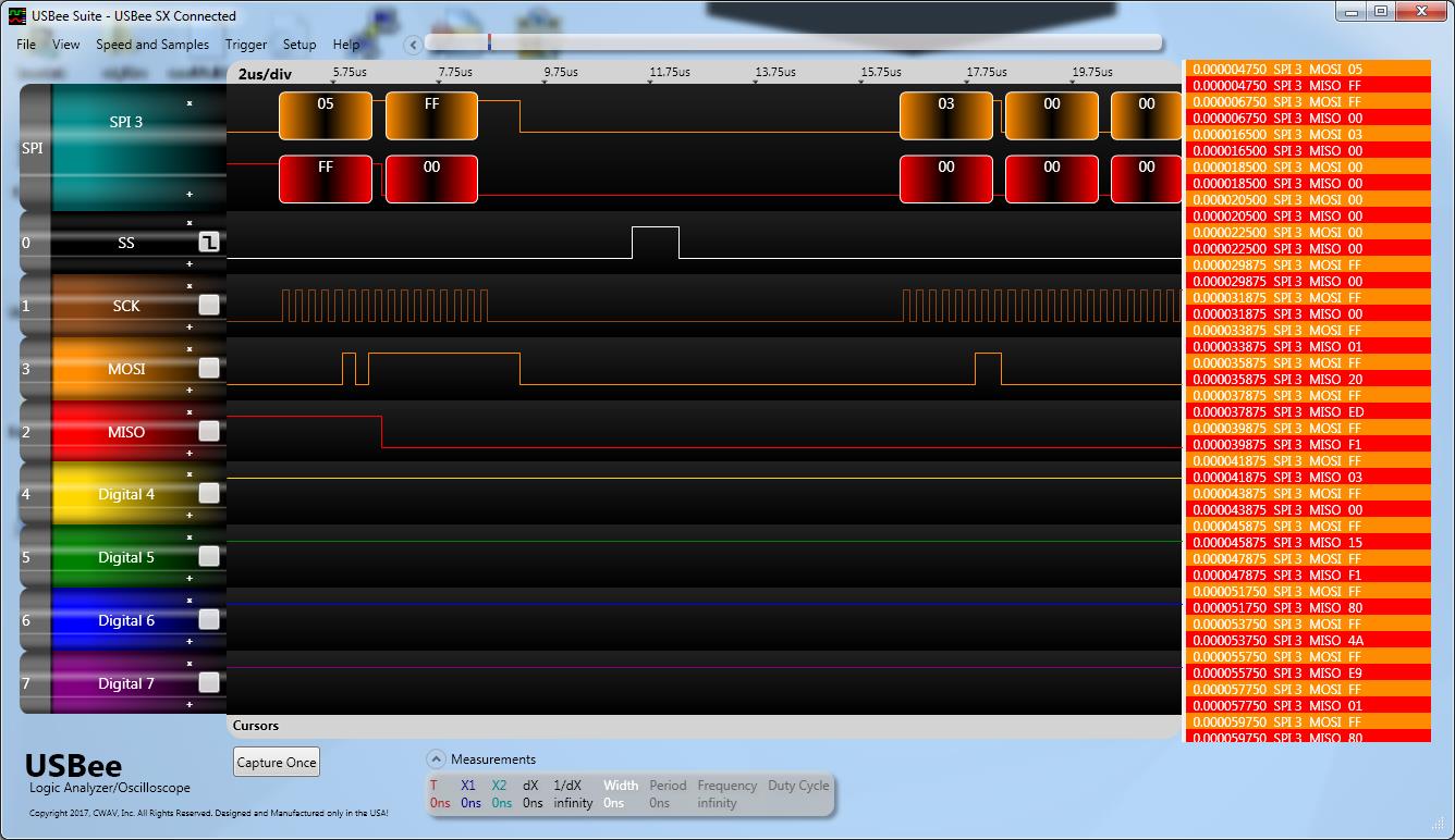
We are interfacing to a SPI Flash MX25R8035F.
When attempting to read 1 page of 256 bytes from the chip we break the read command up into 4 SPI Commands.
1) Read the Status Register to verify that a write isn't in progress (write 1 byte, read 1 byte)
2) Write the read command & address (4 bytes)
3) Read out the 1st 255 bytes of data
4) Read out the last byte of data
I verified through logging that that is data length are being sent into spim_xfer
The reads only work every other time.
When the read fails, the SPI clock stops running after transmitting the Read Status Command. It doesn’t continue to clock in the data.
After the failed read of the status command, the next read of the Flash will succeed.
I have received the same behavior running SDK 3.0.0 and 4.0.2
Is there known issues with reading 1 byte over the SPI interface that leaves the bus in a bad state?
Shown below is scope trace of bad read (only 8 clock cycles)
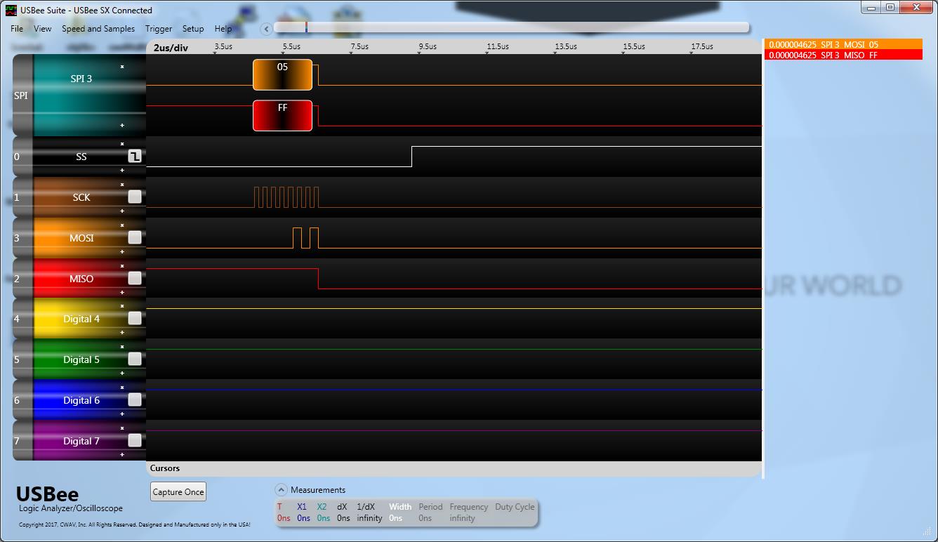
Show below is a scope trace of a good read (16 clock cycles)
Do you know if your MPPT or BMS are configured to send CAN messages periodically without first receiving some external request over CAN?
For example, I know of at least two popular solar car MPPTs that will only send CAN messages in response to corresponding CAN frame with the same ID and with the remote transmission request (RTR) bit set.
You can try to distinguish between a CAN bus where all of the other nodes are declining to send messages and a CAN bus that is non-functional by attempting to send a CAN message and checking if it is ACKed. You should be able to do this in software by checking if the message transmits successfully or in hardware by probing the non-differential CANRX pin on the TJA1050 and checking for the ACK bit using a logic analyzer.
If you don’t have a logic analyzer, you can use a two channel oscilloscope to monitor CANRX and CANTX of the TJA1050. When the MCP2515 transmits a message, CANRX and CANTX will be identical if nobody ACKs your message. If someone does ACK the message, you should see a single dominant (low) bit on CANRX that is not present on CANTX.
You may also want to try swapping out your 100 ohm termination resistor for a 120 ohm termination resistor — all of the CAN devices I’ve used personally have used 120 ohm termination resistors. I don’t expect there would be compatibility issues, but it’s trivial to swap it to rule out the termination resistor as a potential source of error.
Loading
![]()
-
Форум
-
Радар-детекторы
-
Радар-Детекторы : Остальные марки
-
Subini
Subini GRD-H9+
-
Автор темыLinkins
-
Дата начала31.12.2012
-
#281
- Регистрация
- 11.05.2013
- Сообщения
- 3
- Детектор
-
Subini gr-h9
- Авто
-
Volvo S80
-
#282
- Регистрация
- 06.09.2010
- Сообщения
- 7 319
как я понял это в принципе одинаковые модели
Это принципиально разные модели, на разном железе
-
#283
- Регистрация
- 13.05.2013
- Сообщения
- 1
- Детектор
-
GRD-H9+
- Авто
-
Cerato
В чем проблема?
-
#284
- Регистрация
- 16.04.2013
- Сообщения
- 20
- Детектор
-
conqeror H9+
- Авто
-
toyota avensis 2009
Вложения
-
#285

- Регистрация
- 13.03.2013
- Сообщения
- 115
- Детектор
-
h9+/Sho-Me G800-STR
- Авто
-
Вортекс тинго
-
#286
- Регистрация
- 15.05.2013
- Сообщения
- 1
- Детектор
-
conqueror grd-h9+
- Авто
-
Kia
У меня при каждом включении регистратора он просит отформатировать флешку(хотя она была форматирована) и при просмотре записи на регистраторе она трясется, хотя на компе нормально.
Что делать?
-
#287

- Регистрация
- 25.05.2012
- Сообщения
- 59
- Детектор
-
Conqueror 799+
- Авто
-
BMW 3-er, e-90, 2011
-
#288
- Регистрация
- 06.01.2013
- Сообщения
- 11
- Детектор
-
conqeror H9+
- Авто
-
рено логан
-
#289
- Регистрация
- 25.05.2012
- Сообщения
- 59
- Детектор
-
Conqueror 799+
- Авто
-
BMW 3-er, e-90, 2011
-
#290
- Регистрация
- 16.04.2013
- Сообщения
- 20
- Детектор
-
conqeror H9+
- Авто
-
toyota avensis 2009
работает)
Конечно умер. Столько орать на солнце. Я бы тоже умер.
-
#291
- Регистрация
- 25.05.2012
- Сообщения
- 59
- Детектор
-
Conqueror 799+
- Авто
-
BMW 3-er, e-90, 2011
-
#292

- Регистрация
- 13.11.2012
- Сообщения
- 2 646
- Регион
-
Липецк
- Детектор
-
V1 Monaco S Sochi Z EVO S
- Авто
-
Kia
Больше подходит название часы с кукушкой
-
#293
- Регистрация
- 13.03.2013
- Сообщения
- 115
- Детектор
-
h9+/Sho-Me G800-STR
- Авто
-
Вортекс тинго
треноги и стреляния с руки тоже ловит (не знаю названий, чем стреляют).
-
#294

- Регистрация
- 16.05.2011
- Сообщения
- 11 293
- Регион
-
Около Москвы
- Детектор
-
V1
- Авто
-
X-Trail
-
#295
-
#296
- Регистрация
- 16.04.2013
- Сообщения
- 20
- Детектор
-
conqeror H9+
- Авто
-
toyota avensis 2009
-
#297
- Регистрация
- 05.05.2013
- Сообщения
- 3
- Детектор
-
Subini gr-h9+
- Авто
-
kia sorento
Может Вам не повезло, и попался бракованный прибор? Но из видео абсолютно не понятно, почему прибор должен был реагировать на «стрельбу» ДПСника. Он же целился не в вашу машину. Да, похоже, вы ехали со скоростью 50-60 км/ч, а какой лимит срабатывания предупреждений у Вас установлен? Не 50 ли км/ч? Если так, то прибор будет молчать как партизан на допросе.Только раз в час торжественно объявлять время.
У меня из магазина порог установлен 50 км/ч и пока его не превысишь, в машине играет только балалайка. Когда же едешь побыстрей, то все заправки с автоматическими дверями, Стрелки, треноги и прочая хрень — балабонит и пищит без умолку
А качество видео у Вас очень даже ничего!
-
#298
- Регистрация
- 25.05.2012
- Сообщения
- 59
- Детектор
-
Conqueror 799+
- Авто
-
BMW 3-er, e-90, 2011
-
#299
- Регистрация
- 27.12.2012
- Сообщения
- 23
- Регион
-
Москва
- Детектор
-
Neoline X-COP 9100S
- Авто
-
KIA RIO X-LINE
Ни как не могу расстаться с этой коробкой.Китайцы не допиливают прошивку. Вот вам новая модель козырька.В 80-90% спасает от солнечного лазера.
Меня заинтересовало крепление для радар-детектора. Где покупали и сколько стоит?
-
#300
- Регистрация
- 16.04.2013
- Сообщения
- 20
- Детектор
-
conqeror H9+
- Авто
-
toyota avensis 2009
-
Форум
-
Радар-детекторы
-
Радар-Детекторы : Остальные марки
-
Subini
-
На данном сайте используются cookie-файлы, чтобы персонализировать контент и сохранить Ваш вход в систему, если Вы зарегистрируетесь.
Продолжая использовать этот сайт, Вы соглашаетесь на использование наших cookie-файлов.