 25:14
25:14
#92 Замена девелопера Xerox WC 5325 5330 5335 5222 5225 5230 C118 123 | Phaser 5500
 07:21
07:21
Восстановление фьюзера (печки) Xerox WorkCentre 5222, 5225, 5325, 5330, 5335, Pro 123, 128, 133
 05:45
05:45
Заправка WorkCentre Pro 123 / 128 / 133 (006R01182)
 07:15
07:15
#17 Копир Xerox CopyCentre c118 заминает и застревает бумага | Застревание бумаги — ошибка E3-1000
 03:09
03:09
#20 Копир Xerox CopyCentre c123 замятие бумаги | Не печатает | Xerox ошибка — Paper Jam 077-901
 01:05
01:05
Замена тонер картриджа МФУ Xerox M118
 00:25
00:25
Нагревательный вал Xerox CopyCentre C118, WorkCentre M118/M118i
Коды неисправностей
Руководство пользователя Xerox CopyCentre/WorkCentre 118
201
77xxxx
7704xx
Проверьте удаленную машину или телефонную линию. Если
ошибку устранить не удается, обратитесь на Горячую линию Xerox.
7705xx
78xxxx
7804xx
Проверьте удаленную машину или телефонную линию. Если
ошибку устранить не удается, обратитесь на Горячую линию Xerox.
7805xx
79xxxx
7904xx
Проверьте удаленную машину или телефонную линию. Если
ошибку устранить не удается, обратитесь на Горячую линию Xerox.
7905xx
790Bxx
7Axxxx 7A04xx
Проверьте удаленную машину или телефонную линию. Если
ошибку устранить не удается, обратитесь на Горячую линию Xerox.
7A05xx
7Cxxxx 7C01xx
Проверьте удаленную машину или телефонную линию. Если
ошибку устранить не удается, обратитесь на Горячую линию Xerox.
7C03xx
7C04xx
7C05xx
7Dxxxx 7D01xx
Проверьте удаленную машину или телефонную линию. Если
ошибку устранить не удается, обратитесь на Горячую линию Xerox.
7D03xx
7D04xx
7D05xx
7Fxxxx 7F01xx
Проверьте удаленную машину или телефонную линию. Если
ошибку устранить не удается, обратитесь на Горячую линию Xerox.
7F03xx
8Fxxxx 8F04xx
Проверьте удаленную машину или телефонную линию. Если
ошибку устранить не удается, обратитесь на Горячую линию Xerox.
8F05xx
8F0Bxx
91xxxx
9102xx
Проверьте удаленную машину или телефонную линию. Если
ошибку устранить не удается, обратитесь на Горячую линию Xerox.
9107xx
92xxxx
9201xx
Проверьте удаленную машину или телефонную линию. Если
ошибку устранить не удается, обратитесь на Горячую линию Xerox.
9202xx
9207xx
9208xx
9209xx
95xxxx
9508xx
Проверьте удаленную машину или телефонную линию. Если
ошибку устранить не удается, обратитесь на Горячую линию Xerox.
9509xx
Код
Описание и меры по устранению

11 Устранение неисправностей
202
Руководство пользователя Xerox CopyCentre/WorkCentre 118
96xxxx
9608xx
Проверьте удаленную машину или телефонную линию. Если
ошибку устранить не удается, обратитесь на Горячую линию Xerox.
97xxxx
9708xx
Проверьте удаленную машину или телефонную линию. Если
ошибку устранить не удается, обратитесь на Горячую линию Xerox.
9709xx
98xxxx
9808xx
Проверьте удаленную машину или телефонную линию. Если
ошибку устранить не удается, обратитесь на Горячую линию Xerox.
9809xx
99xxxx
9908xx
Проверьте удаленную машину или телефонную линию. Если
ошибку устранить не удается, обратитесь на Горячую линию Xerox.
9909xx
9Axxxx 9A09xx
Проверьте удаленную машину или телефонную линию. Если
ошибку устранить не удается, обратитесь на Горячую линию Xerox.
9Cxxxx 9C02xx
Проверьте удаленную машину или телефонную линию. Если
ошибку устранить не удается, обратитесь на Горячую линию Xerox.
9C07xx
9Dxxxx 9D02xx
Проверьте удаленную машину или телефонную линию. Если
ошибку устранить не удается, обратитесь на Горячую линию Xerox.
9D07xx
9D08xx
9D09xx
9Fxxxx 9F09xx
Проверьте удаленную машину или телефонную линию. Если
ошибку устранить не удается, обратитесь на Горячую линию Xerox.
B0xxxx
Выключите и включите питание. Если ошибку устранить не удается,
обратитесь на Горячую линию Xerox.
B2xxxx B202xx
Выключите и включите питание. Если ошибку устранить не удается,
обратитесь на Горячую линию Xerox.
B203xx
B204xx
B205xx
B207xx
Код
Описание и меры по устранению

Коды неисправностей Руководство пользователя Xerox CopyCentr…
Страница 203
- Изображение
- Текст
Коды неисправностей
Руководство пользователя Xerox CopyCentre/WorkCentre 118
203
B4xxxx B401xx
Выключите и включите питание. Если ошибку устранить не удается,
обратитесь на Горячую линию Xerox.
B402xx
B403xx
B404xx
B405xx
B407xx
B408xx
B409xx
B5xxxx B501xx
Выключите и включите питание. Если ошибку устранить не удается,
обратитесь на Горячую линию Xerox.
B6xxxx B602xx
Выключите и включите питание. Если ошибку устранить не удается,
обратитесь на Горячую линию Xerox.
B7xxxx
Выключите и включите питание. Если ошибку устранить не удается,
обратитесь на Горячую линию Xerox.
E1xxxx
Выключите и включите питание. Если ошибку устранить не удается,
обратитесь на Горячую линию Xerox.
E2xxxx
Выключите и включите питание. Если ошибку устранить не удается,
обратитесь на Горячую линию Xerox.
EPxxxx EP0000
Выключите и включите питание. Если ошибку устранить не удается,
обратитесь на Горячую линию Xerox.
EP0001
EP0002
EP0003
EP0004
EP0005
FFF0xx
Работа выполнена успешно.
FFFCxx
Работа не выполнена.
S10000
Выключите и включите питание. Если ошибку устранить не удается,
обратитесь на Горячую линию Xerox.
S10001
Во время сканирования открылась крышка автоподатчика
оригиналов. Закройте крышку автоподатчика.
S10010
Застрял оригинал. Откройте крышку автоподатчика и удалите
оригиналы.
S10011
Застрял оригинал. Откройте крышку автоподатчика и удалите
оригиналы.
Код
Описание и меры по устранению

11 Устранение неисправностей
204
Руководство пользователя Xerox CopyCentre/WorkCentre 118
S10012
Застрял оригинал большого размера. Откройте крышку
автоподатчика и удалите оригиналы.
S10013
Застрял оригинал малого размера. Откройте крышку автоподатчика
и удалите оригиналы.
S10014
Застрял оригинал. Откройте крышку автоподатчика и удалите
оригиналы.
S10015
Во время сканирования оригиналов открыта крышка стекла
экспонирования. Откройте крышку автоподатчика и удалите
оригиналы.
S10016
Во время сканирования открылась крышка автоподатчика
оригиналов. Закройте крышку автоподатчика.
S10020
Застрял оригинал. Откройте крышку автоподатчика и удалите
оригиналы.
S10021
Застрял оригинал. Откройте крышку автоподатчика и удалите
оригиналы.
S10022
Застрял оригинал большого размера. Откройте крышку
автоподатчика и удалите оригиналы.
S10023
Застрял оригинал малого размера. Откройте крышку автоподатчика
и удалите оригиналы.
S10024
Застрял оригинал. Откройте крышку автоподатчика и удалите
оригиналы.
S10025
Застрял оригинал. Откройте крышку автоподатчика и удалите
оригиналы.
S10026
Во время сканирования оригиналов открыта крышка стекла
экспонирования. Откройте крышку автоподатчика и удалите
оригиналы.
S10027
Во время сканирования открылась крышка автоподатчика
оригиналов. Закройте крышку автоподатчика.
Z-10
Выключите и включите питание. Если ошибку устранить не удается,
обратитесь на Горячую линию Xerox.
003-747, 016-799
Неверно выбрано сочетание параметров печати. Проверьте данные
печати.
016-500
Неправильно указано имя сервера SMTP при передаче ответного
сообщения. Убедитесь, что сервер SMTP указан правильно.
016-501
При использовании протокола POP3 имя сервера POP3 указано
неправильно. Убедитесь, что сервер POP3 указан правильно.
016-502
Сбой регистрации на сервере POP3 при использовании протокола
POP3. Убедитесь, что имя пользователя и пароль для регистрации
на сервере POP3 указаны правильно.
Код
Описание и меры по устранению

Коды неисправностей Руководство пользователя Xerox CopyCentr…
Страница 205
- Изображение
- Текст
Коды неисправностей
Руководство пользователя Xerox CopyCentre/WorkCentre 118
205
016-503
Неправильно указано имя сервера SMTP при передаче
электронной почты. Убедитесь, что сервер SMTP указан правильно.
Также убедитесь, что правильно указан сервер DNS.
016-504
Неправильно указано имя сервера POP3 при передаче электронной
почты. Убедитесь, что сервер POP3 указан правильно. Также
убедитесь, что правильно указан сервер DNS.
016-505
Сбой регистрации на сервере POP3 при передаче электронной
почты. Убедитесь, что имя пользователя и пароль для регистрации
на сервере POP3 указаны правильно.
016-701
Данные печати PCL нельзя обработать из-за нехватки памяти.
Уменьшите разрешение или отмените двустороннюю печать и
мультиизображения.
016-702
Данные печати PCL нельзя обработать из-за недостаточного
объема буфера страницы. Выбирайте из следующих вариантов.
• Уменьшите разрешение в принт-драйвере.
• Увеличьте размер буфера печати.
• Увеличьте память.
016-709
Ошибка при обработке ART EX. Повторите попытку.
016-719
Недостаточно памяти для PCL. Увеличьте память.
016-720
Ошибка команды PCL. Проверьте установки печати или исправьте
команду PCL.
016-721
Ошибка при выполнении работы печати. Повторите попытку. Если
ошибку устранить не удается, обратитесь на Горячую линию Xerox.
016-726
Невозможно выбрать язык принтера. Выберите язык принтера.
016-730
Обнаружена команда, которая не поддерживается. Проверьте
данные печати, удалите команду, из-за которой произошла ошибка,
и повторите попытку.
016-732
Форма, указанная в настройках эмуляции, не зарегистрирована на
хосте. Повторите передачу данных формы.
016-744
Невозможно распечатать файл PDF, так как он содержит свойства,
которые аппарат не поддерживает. Чтобы распечатать файл,
откройте его в Adobe Reader, и выберите команду [Print] из меню
[File].
016-749
Ошибка синтаксиса команды PJL. Проверьте установки печати или
исправьте команду PJL.
016-751
Невозможно распечатать файл PDF с помощью утилиты
ContentsBridge. Чтобы распечатать файл, откройте его в Adobe
Reader, и выберите команду [Print] из меню [File].
Код
Описание и меры по устранению

11 Устранение неисправностей
206
Руководство пользователя Xerox CopyCentre/WorkCentre 118
016-752
Невозможно распечатать файл PDF с помощью утилиты
ContentsBridge из-за нехватки памяти. Измените режим печати в
ContentsBridge и повторите попытку.
• Если был выбран режим высокого качества, измените его на
стандартное.
• Если был выбран режим стандартного качества, измените его на
режим быстрой печати.
016-753
Неверно введен пароль для прямой печати. Введите правильный
пароль.
016-754
Невозможно распечатать файл PDF, так как он содержит объекты,
сжатые с помощью алгоритма LZW.
Распечатайте файл следующим образом.
• Откройте его в Adobe Reader, и выберите команду [Print] из меню
[File].
• Используйте режим PostScript.
016-755
Невозможно распечатать файл PDF, так как он защищен от печати.
Откройте файл в Adobe Acrobat (не Adobe Reader) и снимите
флажок с настройки [No Printing] в установках Document Security.
Распечатайте файл.
016-757
Введен неправильный пароль. Введите правильный пароль.
016-758
Счет не разрешается копировать. Свяжитесь с главным
оператором.
016-759
Достигнуто максимальное количество копий. Свяжитесь с главным
оператором.
016-760
Ошибка при обработке PostScript. Выбирайте из следующих
вариантов.
• Оптимизируйте скорость в принт-драйвере.
• Увеличьте размер буфера печати.
• Увеличьте память PostScript.
016-761
Ошибка при обработке изображения. Оптимизируйте скорость в
принт-драйвере и повторите попытку. Если ошибка повторяется,
установите более высокую совместимость и повторите попытку.
016-762
Указан командный язык принтера, не поддерживаемый машиной.
Укажите язык принтера на экране [Режим печати].
016-764
Не удалось соединиться с сервером SMTP. Свяжитесь с главным
оператором.
016-765
Невозможно отправить электронную почту, так как диск сервера
SMTP переполнен. Свяжитесь с главным оператором.
016-766
Ошибка сервера SMTP. Свяжитесь с главным оператором.
016-767
Невозможно отправить электронную почту, так как указан неверный
адрес. Проверьте адрес электронной почты, и повторите попытку.
Код
Описание и меры по устранению

Коды неисправностей Руководство пользователя Xerox CopyCentr…
Страница 207
- Изображение
- Текст
Коды неисправностей
Руководство пользователя Xerox CopyCentre/WorkCentre 118
207
016-768
Невозможно соединиться с сервером SMTP, так как указан
неверный адрес электронной почты машины. Проверьте адрес
электронной почты машины.
016-769
Сервер SMTP не поддерживает подтверждения о доставке (DSN).
Отправьте электронную почту, не устанавливая подтверждения.
016-790
Недостаточно памяти для электронной почты. В этом случае
выполните следующее.
• Уменьшите разрешение сканирования.
• Уменьшите область сканирования.
• Увеличьте память принтера.
081-702
Неверно выбран параметр передачи факса. Проверьте настройки
принт-драйвера.
081-703
Недостаточно памяти для передачи факса. Разделите документ для
передачи, уменьшите разрешение или удалите из памяти ненужные
данные.
081-704
Обработка задания остановлена пользователем.
081-705
Указанная функция недоступна. Проверьте статус машины.
081-706,707
Ошибка при работе в режиме факса. После того, как экран на
панели управления будет выключен, выключите и включите
питание аппарата.
081-709
Ошибка передачи при работе в режиме факса. Проверьте
телефонную линию и попробуйте передать снова.
081-720,722
Ошибка машины. После того, как экран на панели управления будет
выключен, выключите и включите питание аппарата.
081-721
Обработка задания остановлена пользователем.
C1-3, C2-2, C2-3,
C3-1, C3-2, C3-3,
C4-0, C4-1, C4-2,
C4-3
Застревание в лотке для бумаги. См. раздел Застревание бумаги
на стр. 184.
C6-1, C6-2
Застревание бумаги в дуплексном модуле. См. раздел
Застревание бумаги на стр. 184.
C8-2, C8-3, C8-4
Застревание в лотке для бумаги. См. раздел Застревание бумаги
на стр. 184.
C8-6
Застревание бумаги в дуплексном модуле. См. раздел
Застревание бумаги на стр. 184.
C9-3
Застревание бумаги в лотке 5 (обходном). См. раздел Застревание
бумаги на стр. 184.
E1-6
Застревание бумаги внутри аппарата. См. раздел Застревание
бумаги на стр. 184.
Код
Описание и меры по устранению

11 Устранение неисправностей
208
Руководство пользователя Xerox CopyCentre/WorkCentre 118
Качество изображения
Качество изображения зависит от разных факторов. Чтобы обеспечить
оптимальное качество изображения, проверьте следующее. Если проблему
решить не удается, свяжитесь с главным оператором.
• Не размещайте машину под прямыми солнечными лучами или вблизи
устройств отопления.
• Регулярно чистите указанные в руководстве зоны — стекло экспонирования,
стекло сканирования через автоподатчик и выходные лотки. См. раздел в
главе Техническое обслуживание на стр. 177.
E3-1, E1-2, E1-1
Застревание бумаги на выходе. См. раздел Застревание бумаги на
стр. 184.
E3-6
Застревание бумаги на выходе. См. раздел Застревание бумаги на
стр. 184.
E8-2
Застревание бумаги в дуплексном модуле. См. раздел
Застревание бумаги на стр. 184.
H1-2, H1-3, H1-4,
H2-7, H3-1, H4-1,
H4-2, H4-3, H4-4,
H7-3, H7-4, H7-7,
H8-1, H8-2, H8-3,
H8-4, H9-3, H9-4
Выключите и включите питание. Если ошибку устранить не удается,
обратитесь на Горячую линию Xerox.
J1-2
Закончился тонер. См. Замена тонер-картриджа на стр. 181.
J3-1
Принт-картридж установлен неправильно. Установите принт-
картридж правильно.
J4-1, J6-1, J7-1,
J7-2, J7-3
Замените принт-картридж. См. Замена принт-картриджа на
стр. 178.
J8-1, J8-2, J8-3
Замените тонер-картридж. См. Замена тонер-картриджа на
стр. 181.
U0-1, U0-2, U1-1,
U3-5, U4-1, U4-2,
U4-3, U4-9, U5-1,
U6-2, U6-3, U6-4,
U6-5, U6-6
Выключите и включите питание. Если ошибку устранить не удается,
обратитесь на Горячую линию Xerox.
Код
Описание и меры по устранению

Горячая линия Xerox
Руководство пользователя Xerox CopyCentre/WorkCentre 118
209
Горячая линия Xerox
Для получения справки. За дополнительной помощью при работе с копиром
CopyCentre или копиром/принтером WorkCentre обращайтесь к следующим
источникам:
1) См. в данном руководстве
2) Обращайтесь к главному оператору
3) Посетите Web-сайт www.xerox.com или обратитесь на Горячую линию Xerox
При обращении на Горячую линию сообщите серийный номер машины.
Для обращения на Горячую линию потребуется следующая информация:
описание проблемы, серийный номер машины, код ошибки (при наличии), а
также название и местоположение вашей организации. Чтобы посмотреть
серийный номер машины, выполните следующее.
1.
Нажмите кнопку <Статус машины> на
панели управления.
2.
Выберите [Счетчик отпечатков] на
экране [Статус машины] с помощью
кнопки <Выбор> и нажмите кнопку
<Ввод>.
3.
Вы увидите серийный (заводской)
номер.
ПРИМЕЧАНИЕ: Кроме того, серийный номер находится на металлической
пластинке с левой стороны аппарата за крышкой A. Для получения подробной
информации см. раздел Горячая линия Xerox в главе Перед началом
использования аппарата на стр. 11.
<Статус машины>

11 Устранение неисправностей
210
Руководство пользователя Xerox CopyCentre/WorkCentre 118

Комментарии
Scanner Motor Troubleshooting Procedure (Continued)
Step
Actions and Questions
4
Check the Laser connections.
Are P/J130, P/J620 and P/J406
connected?
5
Check continuity between the Laser and
the Engine Logic Board.
Is there continuity on each wire
between P/J140 <=> P/J406?
6
Check continuity between the Laser and
the Engine Logic Board.
Is there continuity on each wire
between P/J130 <=> P/J406?
7
Check for +5 V to the Laser.
Is there +5 V across P/J140-8 (+) <=>
ground?
8
Check for +24 V to the Laser.
Is there +24 V across P/J130-5 (+) <=>
ground?
Note
Following display of this error, leave power applied for 7 minutes, then cycle
printer power. If the error reoccurs, procede with troubleshooting procedure.
The Fuser failed to reach temperature within the warm-up period. Possible faults are:
During the Warm-Up period, the Control Thermistor does not detect the
Ready temperature even when the specified time has passed.
During the Standby period, the Control Thermistor does not detect the
required temperature even when the specified time has passed.
During the Standby period, the Control Thermistor does not detect the
required temperature even when the specified time has passed.
During idling after power-on, the Control Thermistor does not detect the
idling stop temperature even after the specified time has passed.
During print, the Control Thermistor does not detect the required
temperature even when the specified time has passed.
Error Messages, Codes, and Procedures
Yes
Go to Step 5.
Go to Step 6.
Go to Step 7.
Go to Step 8.
Replace the Laser
assembly
(page 8-74).
No
Connect P/J130,
P/J620 and P/
J406.
Repair the wiring.
Repair the wiring.
Replace the
Engine Logic
Board
(page 8-89).
Replace the
Engine Logic
Board
(page 8-89).
3-27
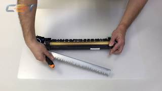
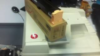
Вообще, ошибки U4 — это ошибки фьюзера (печки) — не прогревается, перегревается и прочие.
Внезапно ХРЯСЬ и МФУ пишет U4… Если нажать на кнопку START (зеленая такая), то появится код этой ошибки U4.
Теперь подробно о том, как лечитьНажимаеми удерживаем кнопку 0 (ноль) на клавиатуре более 4 секунд, а затем нажимаем кнопку [Start], удерживая в то же время нажатой кнопку 0. Отпускаем и видим [С_]. Теперь, чтобы сбросить ошибку U4-1, нужно нажать 5020, моргнет 0 (ноль). Все, перезагружаем аппарат и наслаждаемся
You are here: Home / error code / Xerox Phaser 5500 error and solving error codes
– Compatible Printer model: Xerox Phaser 5500
– Xerox Phaser 5500 Error Codes with quick guides:
- Code: E1-1
- Description: Paper Size Jam – E1-1 Regi Area Jam Paper did not pass the Registration Sensor located behind Door A, within the specified time.
- Causes: • Registration Sensor • Registration Clutch • Take Away Roller • Engine Control Board
- Troubleshooting Guides: 1 Check paper position at Door A or B. Does the paper touch the Registration Sensor or Feeder’s Pre-Feed Sensor? Remove the paper. Go to Step 2. 2 Check the Take Away Roller. Open Door A. Is the Take Away Roller worn or contaminated with paper dust? Clean or replace the Take Away Roller. Go to Step 3. 3 Test the Registration Sensor. 1. Open Door A. 2. Run the Service Diagnostics Registration Sensor test. Does the sensor change state? Go to Step 7. Go to Step 4. 4 Check the Registration Sensor connection. Are P/J104 and P/J403B connected? Go to Step 5. Connect the sensor. 5 Check continuity between the Registration Sensor and Engine Control Board. Is there continuity on each wire between P/ J104 <=> P/J403? Go to Step 6. Repair the wiring. 6 Check for +5 V at the Registration Sensor. Is there +5 V across the sensor connector’s P/J104-1 <=> ground? Replace the Registration Sensor. Replace the Engine Control Board. 7 Test the Registration Clutch operation.Run the Service Diagnostics Registration Clutch test. Does the clutch operate properly? Replace the Engine Control Board (page 8-89). Go to Step 8. 8 Check the Registration Clutch connection. Are P/J215 and P/J403B connected? Go to Step 9. Connect P/J215 and P/J403B. 9 Check continuity between the Registration Clutch and Engine Control Board. Is there continuity on each wire between P/ J215 <=> P/J403? Go to Step 10. Repair the wiring. 10 Check for +24 V to the Registration Clutch. Is there +24 V across P215-2 (+) <=> ground? Go to Step 11. Replace the Engine Control Board. 11 Check Registration Clutch resistance. Replace the Engine Control Board. Replace Registration Clutch.
- Code: E1-2
- Description: Jam at A – E1-2 Regi Area Jam Paper did not activate the Fuser Exit Sensor, located behind Door A, within the specified time following activation of the Registration Clutch. NOTE: If the printer exhibits first sheet jams following power On or Power Saver mode and reports Jam Code E1-2, check actuator motion on the Fuser Exit Sensor Assembly. Accumulations of toner, when cool, can bind the actuator on earlier versions of the assembl
- Causes: • Fuser Exit Sensor • Registration Clutch • Take Away Roller • Exit PWB • Engine Control Board
- Troubleshooting Guides: 1 Check paper position behind Door A. Does the paper touch the Fuser Exit Sensor? Remove the paper. Go to Step 2. 2 Check the Take Away Roller. Is the Take Away Roller worn or contaminated with paper dust? Clean or replace the Take Away Roller. Go to Step 3. 3 Test the Fuser Exit Sensor. 1. Open Door A. 2. Run the Service Diagnostics Fuser Exit Sensor test. Does the sensor change state? Go to Step 7. Go to Step 4. 4 Check the Fuser Exit Sensor connection. Are P/J125 and P/J410 connected? Go to Step 5. Connect the sensor. 5 Check continuity between the Fuser Exit Sensor and Engine Control Board. Is there continuity on each wire between P/ J125 <=> P/J410? Go to Step 6. Repair the wiring. 6 Check for +5 V at the Fuser Exit Sensor. Is there +5 V across the sensor connector’s P/J125-3 <=> ground? Replace the Fuser Exit Sensor. Replace the Engine Control Board 7 Test the Registration Clutch operation. Run the Service Diagnostics Registration Clutch test. Does the clutch operate properly? Replace the Engine Control Board. Go to Step 8. 8 Check the Registration Clutch connection. Are P/J215 and P/J403B connected? Go to Step 9. Connect P/J215 and P/J403B. 9 Check continuity between the Registration Clutch and Engine Control Board. Is there continuity on each wire between P/ J215 <=> P/J403B? Go to Step 10. Repair the wiring. 10 Check for +24 V to the Registration Clutch. Is there +24 V across P215-2 (+) <=> ground? Go to Step 11. Replace the Engine Control Board. 11 Check Registration Clutch resistance. Is the resistance between J215-1 and J215- 2 approximately 240 ohms? Replace the Engine Control Board. Replace Registration Clutch.
- Code: E1-6
- Description: Jam at A – E1-6 Regi Area Jam Paper remains at the Registration Sensor located behind Door A.
- Causes: • Registration Sensor • Engine Control Board
- Troubleshooting Guides: 1 Check paper position at Door A. Is paper touching the Registration Sensor? Remove the paper. Go to Step 2. 2 Test the Registration Sensor. 1. Open Door A. 2. Run the Service Diagnostics Registration Sensor test. Does the sensor change state? Replace the Engine Control Board. Go to Step 3. 3 Check the Registration Sensor connection. Are P/J104 and P/J403 connected? Go to Step 4. Connect the sensor. 4 Check continuity between the Registration Sensor and Engine Control Board. Is there continuity on each wire between P/ J104 <=> P/J403? Go to Step 5. Repair the wiring. 5 Check for +5 V at the Registration Sensor. Is there +5 V across the sensor connector’s P/J104-1 <=> ground? Replace the Registration Sensor. Replace the Engine Control Board.
- Code: E3-1, E3-2
- Description: Jam at A – Fuser Area Jam Paper did not actuate the Fuser Exit Sensor, located behind Door A, within the specified time. • Jam at A – E3-1 Fuser Area Jam • Jam at A – E3-2 Fuser Area Jam
- Causes: • Fuser Exit Sensor • Take Away Roller • Engine Control Board • Fuser
- Troubleshooting Guides: 1 Check paper position. Open Door A. Does the paper touch the Fuser Exit Sensor? Remove the paper. Go go step 2. 2 Check the Fuser for a paper jam. Open Door A. Is there a paper jam in the Fuser? Go to Step 3. Remove the paper. 3 Check the Fuser installation. Open Door A. Is the Fuser installed correctly? Go to Step 4. Correct the installation. 4 Check the Take Away Roller. Open Door A. Is the Take Away Roller worn or contaminated with paper dust? Go to Step 5. Clean or replace Take Away Roller. 5 Test the Fuser Exit Sensor operation. 1. Open Door A. 2. Run the Service Diagnostic Fuser Exit Sensor test. Does the sensor state change each time paper touches the sensor? Reconnect the connector of the Engine Control Board. Go to Step 6. 6 Check the Fuser Exit Sensor connection. Are P/J125 and P/J410 connected? Go to Step 7. Connect P/J125 and P/J410. 7 Check continuity between the Fuser Exit Sensor and Engine Control Board. Is there continuity on each wire between P/ J125 <=> P/J410? Go to Step 8. Repair the wiring. 8 Check for +5 V to the Fuser Exit Sensor. Is there +5 V across J125-3 (+) <=> ground? Replace the Fuser Exit Sensor. Replace Engine Control Board
- Code: E3-6
- Description: Jam at A – E3-6 Fuser Area Jam Paper remains at the Fuser Exit Sensor located behind Door A.
- Causes: • Fuser Exit Sensor • Engine Control Board
- Troubleshooting Guides: 1 Check paper position at Door A. Is paper touching the Fuser Exit Sensor? Remove the paper. Go to Step 2. 2 Test the Fuser Exit Sensor. 1. Open Door A. 2. Run the Service Diagnostics Fuser Exit Sensor test. Does the sensor change state? Replace the Engine Control Board. Go to Step 3. 3 Check the Fuser Exit Sensor connection. Are P/J125 and P/J410 connected? Go to Step 4. Connect the sensor. 4 Check continuity between the Fuser Exit Sensor and Engine Control Board. Is there continuity on each wire between P/ J125 <=> P/J410? Go to Step 5. Repair the wiring. 5 Check for +5 V at the Fuser Exit Sensor. Is there +5 V across the sensor connector’s P/J125-3 <=> ground? Replace the Fuser Exit Sensor. Replace the Engine Control Board.
- Code: E4-1
- Description: Jam at A – E4-1 Exit 2 Area Jam Paper did not reach the Exit 2 Exit Sensor located behind Door E on time.
- Causes: • Fuser Exit Sensor • Exit 2 Exit Sensor • Exit 1 OCT Roller • Exit 1 Motor • Exit PWB • Engine Control Board • LVPS
- Troubleshooting Guides: 1 Check paper position at Door A. Is paper touching the Fuser Exit Sensor? Remove the paper. Go to Step 2. 2 Check paper position at Door E. Is paper touching the Exit Sensor? Remove the paper. Go to Step 3. 3 Check the OCT Roller. Is the OCT Roller worn or contaminated with paper dust? Clean or replace the OCT Roller. Go to Step 4. 4 Check the drive transmission. Does the OCT Roller and gears rotate smoothly? Go to Step 5. Restore proper operation. 5 Test the Fuser Exit Sensor. 1. Open Door A. 2. Run the Service Diagnostics Fuser Exit Sensor test. Does the sensor change state? Go to Step 9. Go to Step 6. 6 Check the Fuser Exit Sensor connection. Are P/J125 and P/J410 connected? Go to Step 7. Connect the sensor. 7 Check continuity between the Fuser Exit Sensor and Engine Control Board. Is there continuity on each wire between P/ J125 <=> P/J410? Go to Step 8. Repair the wiring. 8 Check for +5 V at the Fuser Exit Sensor. Is there +5 V across the sensor connector’s P/J125-3 <=> ground? Replace the Fuser Exit Sensor. Replace the Engine Control Board 9 Test the Exit 1 Motor operation. Run the Service Diagnostics Exit 1 Motor tests. Does the motor operate properly? Go to Step 18. Go to Step 10. 10 Check the Exit 1 Motor connection. Are P/J206 and P/J432 connected? Go to Step 11. Connect P/J206 and P/J432. 11 Check continuity between the Exit 2 Motor and Engine Control Board. Is there continuity on each wire between P/ J206 <=> P/J432? Go to Step 12. Repair the wiring. 12 Check for +24 V to the Exit 1 Motor. Is there +24 V across P206-5 (+) <=> ground? Replace the Exit 1 Offset Motor. Go to Step 13. 13 Check the connection between the Exit PWB and Engine Control Board. Are P/J431 and P/J421 connected? Go to Step 14. Connect P/J431 and P/J421. 14 Check continuity between the Exit PWB and the Engine Control Board. Is there continuity on each wire between P/ J431 <=> P/J421? Go to Step 15. Repair the wiring. 15 Check the connection between the Exit PWB and the LVPS. Are P/J430 and P/J526 connected? Go to Step 16. Connect P/J430 and P/J526. 16 Check continuity between the Exit PWB and the LVPS. Is there continuity on each wire between P/ J430 <=> P/J526? Go to Step 17. Repair the wiring. 17 Check for +24 V to the Exit PWB. Is there +24 V across P/J430-1 (+) <=> ground? Replace the Exit PWB. Replace the LVPS. 18 Test the Exit 2 Exit Sensor. 1. Open Door E. 2. Run the Service Diagnostics Exit Sensor test. Does the sensor change state? Replace the Engine Control Board. Go to Step 19. 19 Check the Exit 2 Exit Sensor connection. Are P/J112, P/J606B, and P/J434 connected? Go to Step 20. Connect the sensor. 20 Check continuity between the Exit 2 Exit Sensor and Exit PWB. Is there continuity on each wire between P/ J112 <=> P/J434? Go to Step 21. Repair the wiring. 21 Check for +5 V at the Exit 2 Exit Sensor. Is there +5 V across the sensor connector’s P/J112-3 <=> ground? Replace the Exit Sensor. Go to Step 2 22 Check the connection between the Exit PWB and Engine Control Board. Go to Step 23. Connect P/J431 and P/J421. 23 Check continuity between the Exit PWB and Engine Control Board. Is there continuity on each wire between P/ J431 <=> P/J421? Go to Step 24. Repair the wiring. 24 Check the connection between the Exit PWB and the LVPS. Are P/J430 and P/J526 connected? Go to Step 25. Connect P/J430 and P/J526. 25 Check continuity between the Exit PWB and the LVPS. Is there continuity on each wire between P/ J430 <=> P/J526? Go to Step 26. Repair the wiring. 26 Check for +24 V to the Exit PWB. Is there +24 V across P/J430-1 (+) <=> ground? Replace the Exit PWB. Replace the LVPS
- Code: E4-3, E4-5
- Description: Jam at E – E4-3 Exit 2 Area Jam Paper did not pass the Exit 2 Exit Sensor located behind Door E on time. • Jam at E – E4-3 Exit 2 Area Jam • Jam at A – E4-5 Exit 2 Area Jam
- Causes: • Exit 2 Exit Sensor • Exit 2 Motor • Exit 2 OCT Roller • Exit 2 FU Roller • Exit 2 Inv Roller • Exit PWB • Engine Control Board • LVPS
- Troubleshooting Guides: 1 Check paper position at Door E. Is paper touching the Exit 2 Sensor? Remove the paper. Go to Step 2. 2 Check the FU Roller. Is the FU Roller worn or contaminated with paper dust? Clean or replace the FU Roller. Go to Step 3. 3 Check the drive transmission. Does the FU Roller and gears rotate smoothly? Go to Step 4. Restore proper operation. 4 Check the Inv Roller. Is the INV Roller worn or contaminated with paper dust? Clean or replace the INV Roller. Go to Step 5. 5 Check the drive transmission. Does the INV Roller and gears rotate smoothly? Go to Step 6. Restore proper operation. 6 Check the OCT Roller. Is the OCT Roller worn or contaminated with paper dust? Clean or replace the OCT Roller. Go to Step 7. 7 Check the drive transmission. Does the OCT Roller and gears rotate smoothly? For E4-5: Go to Step 8. For E4-3: Go to Step 9. Restore proper operation. 8 For E4-5 Only: Test Exit 2 Gate Solenoid. Run the Service Diagnostics Exit 2 Gate Solenoid test. Does the Solenoid operate the Gate? Go to Step 9. Go to Step 10. 9 Test the Exit 2 Sensor. 1. Open Door E. 2. Run the Service Diagnostics Exit Sensor test. Does the sensor change state? For E4-5: Go to Step 10. For E4-3: Go to Step 12. Go to Step12. 10 For E4-5 Only: Check Exit 2 Solenoid. Check continuity on each wire between P/ J209 to P/J433. Is there continuity on each wire between P/ J209 to P/J433. Go to Step 11. Repair the wiring. 11 For E4-5 Only: Check for +24 V to the Exit 2 Gate Solenoid. Is there +24 V across P/J433-11 (+) <=> ground? Replace the Exit 2 Gate Solenoid. Replace the Exit PWB. 12 Check the Exit Sensor connection. Are P/J112, P/J606B, and P/J434 connected? Go to Step 13. Connect the sensor. 13 Check continuity between the Exit Sensor and Exit PWB. Is there continuity on each wire between P/ J112 <=> P/J434? Go to Step 14. Repair the wiring. 14 Check for +5 V at the Exit Sensor. Is there +5 V across the sensor connector’s P/J112-3 <=> ground? Replace the Exit 2 Sensor. Go to Step 15. 15 Check the connection between the Exit PWB and Engine Control Board. Are P/J431 and P/J421 connected? Go to Step 16. Connect P/J431 and P/J421. 16 Check continuity between the Exit PWB and the Engine Control Board. Is there continuity on each wire between P/ J431 <=> P/J421? Go to Step 17. Repair the wiring. 17 Check the connection between the Exit PWB and the LVPS. Are P/J430 and P/J526 connected? Go to Step 18. Connect P/J430 and P/J526. 18 Check continuity between the Exit PWB and the LVPS. Is there continuity on each wire between P/ J430 <=> P/J526? Go to Step 19. Repair the wiring. 19 Check for +24 V to the Exit PWB. Is there +24 V across P/J430-1 (+) <=> ground? Replace the Exit PWB. Replace the LVPS. 20 Test the Exit 2 Motor operation. Run the Service Diagnostics Exit 2 Output Motor tests. Does the Exit 2 Motor operate properly? Replace the Engine Control Board. Go to Step 21. 21 Check the Exit 2 Motor connection. Are P/J208, P/J606A and P/J433 connected? Go to Step 22. Connect P/J208, P/J606A and P/ J433. 22 Check continuity between the Exit 2 Motor and Exit PWB. Is there continuity on each wire between P/ J208 <=> P/J433? Go to Step 23. Repair the wiring. 23 Check for +24 V to the Exit 2 Motor. Is there +24 V across P208-5 (+) <=> ground? Replace the Exit 2 Motor. Go to Step 24. 24 Check the connection between the Exit PWB and Engine Control Board. Are P/J431 and P/J421 connected? Go to Step 25. Connect P/J431 and P/J421. 25 Check continuity between the Exit PWB and Engine Control Board. Is there continuity on each wire between P/ J431 <=> P/J421? Go to Step 26. Repair the wiring. 26 Check the connection between the Exit PWB and the LVPS. Are P/J430 and P/J526 connected? Go to Step 27. Connect P/J430 and P/J526. 27 Check continuity between the Exit PWB and the LVPS. Is there continuity on each wire between P/ J430 <=> P/J526? Go to Step 28. Repair the wiring. 28 Check for +24 V to the Exit PWB. Is there +24 V across P/J430-1 (+) <=> ground? Replace the Exit PWB. Replace the LVPS.
- Code: E4-6
- Description: Jam at E – E4-6 Exit 2 Area Jam Paper remains at the Exit 2 Exit Sensor located behind Door E.
- Causes: • Exit 2 Exit Sensor • Exit PWB • Engine Control Board • LVPS
- Troubleshooting Guides: 1 Check paper position at Door A. Is paper touching the Fuser Exit Sensor? Remove the paper. Go to Step 2. 2 Test the Exit Sensor. Run the Service Diagnostics Exit Sensor test. Does the sensor change state? Replace the Engine Control Board. Go to Step 3. 3 Check the Exit Sensor connection. Are P/J112, P/J606B and P/J434 connected? Go to Step 4. Connect the sensor. 4 Check continuity between the Exit Sensor and Exit PWB. Is there continuity on each wire between P/ J112<=> P/J434? Go to Step 5. Repair the wiring. 5 Check for +5 V at the Exit Sensor. Is there +5 V across the sensor connector’s P/J112-3 <=> ground? Replace the Exit Sensor. Go to Step 6. 6 Check the connection between the Exit PWB and Engine Control Board. Are P/J431 and P/J421 connected? Go to Step 7. Connect P/J431 and P/J421. 7 Check continuity between the Exit PWB and Engine Control Board. Is there continuity on each wire between P/ J431 <=> P/J421? Go to Step 8. Repair the wiring. 8 Check the connection between Exit PWB and LVPS. Are P/J430 and P/J526 connected? Go to Step 9. Connect P/J430 and P/J526. 9 Check continuity between the Exit PWB and LVPS. Is there continuity on each wire between P/ J430 <=> P/J526? Go to Step 10. Repair the wiring. 10 Check for +24 V to the Exit PWB. Is there +24 V across P/J430-1 (+) <=> ground? Replace the Exit PWB. Replace the LVPS.
- Code: E8-2
- Description: Jam at E – E8-2 Duplex Area Jam Paper being fed into the Duplex Unit did not reach the Wait Sensor on time.
- Causes: • Duplex Wait Sensor • Exit 2 Motor • Exit 2 OCT Roller • Exit 2 FU Roller • Exit 2 Inv Roller • Exit PWB • Duplex Unit PWB • Engine Control Board • LVPS
- Troubleshooting Guides: 1 Check paper position at Door E. Does paper remain in Exit 2? Remove the paper. Go to Step 2. 2 Check the FU Roller. Is the FU Roller worn or contaminated with paper dust? Clean or replace the FU Roller. Go to Step 3. 3 Check the drive transmission. Does the FU Roller and gears rotate smoothly? Go to Step 4. Restore proper operation. 4 Check the Inv Roller. Is the INV Roller worn or contaminated with paper dust? Clean or replace the INV Roller. Go to Step 5. 5 Check the drive transmission. Does the INV Roller and gears rotate smoothly? Go to Step 6. Restore proper operation. 6 Check the OCT Roller. Is the OCT Roller worn or contaminated with paper dust? Clean or replace the OCT Roller. Go to Step 7. 7 Check the drive transmission. Does the OCT Roller and gears rotate smoothly? Go to Step 8. Restore proper operation. 8 Test the Exit 2 Motor. Run the Service Diagnostics Exit 2 Motor tests. Does the Exit 2 Motor operate properly? Go to Step 17. Go to Step 9. 9 Check the Exit 2 Motor connections. Are P/J208, P/J606A and P/J433 connected? Go to Step 10. Connect P/J208, P/J606A and P/ J433. 10 Check continuity between the Exit Motor and Exit PWB. Is there continuity on each wire between P/ J208 <=> P/J433? Go to Step 11. Repair the wiring. 11 Check for +24 V to the Exit 2 Motor. Is there +24 V across P208-5 (+) <=> ground? Replace the Exit 2 Motor. Go to Step 12. 12 Check the connection between the Exit PWB and Engine Control Board. Are P/J431 and P/J421 connected? Go to Step 13. Connect P/J431 and P/J421. 13 Check continuity between the Exit PWB and the Engine Control Board. Is there continuity on each wire between P/ J431 <=> P/J421? Go to Step 14. Repair the wiring. 14 Check the connection between the Exit PWB and the LVPS. Are P/J430 and P/J526 connected? Go to Step 15. Connect P/J430 and P/J526. 15 Check continuity between the Exit PWB and the LVPS. Is there continuity on each wire between P/ J430 <=> P/J526? Go to Step 16. Repair the wiring. 16 Check for +24 V to the Exit PWB. Is there +24 V across P/J430-1 (+) <=> ground? Replace the Exit PWB. Replace the LVPS. 17 Test the Wait Sensor. Run the Service Diagnostics Duplex Wait Sensor test. Does the Wait Sensor operate properly? Replace the Engine Control Board. Go to Step 18. 18 Check the Wait Sensor connection. Are P/J123 and P/J541 connected? Go to Step 19. Connect P/J123 and P/J541. 19 Check continuity between the Wait Sensor and Duplex PWB. Is there continuity on each wire between P/ J123 <=> P/J541? Go to Step 20. Repair the wiring. 20 Check for +5 V to the Wait Sensor. Is there +5 V across P123-3 (+) <=> ground? Replace the Wait Sensor. Go to Step 21. 21 Check the Duplex PWB connection. Are P/J540 and P/J417 connected? Go to Step 22. Connect P/J540 and P/J417 surely. 22 Check continuity between the Duplex PWB and Engine Control Board. Is there continuity on each wire between P/ J540 <=> P/J417? Go to Step 23. Repair the wiring. 23 Check for +5 V to the Duplex PWB. Is there +5 V across P/J540-1 (+) <=> ground? Replace the Duplex PWB. Replace the Engine Control Board.
- Code: H1-1 … H1-4
- Description: Tray n Failure – H1 -1/2/3/4 Tray n Fail Detected lift failure. Paper size detection inoperative. • Tray 2 Failure – H1-1 Tray 2 Fail • Tray 3 Failure – H1-2 Tray 3 Fail • Tray 4 Failure – H1-3 Tray 4 Fail • Tray 5 Failure – H1-4 Tray 5 Fail
- Causes: • Tray • Feeder • Feed/Lift Motor • Level Sensor • Paper Size Switch • Tray 4-5 PWB • Engine Control Board
- Troubleshooting Guides: 1 Check paper supply. Is paper loaded in the affected tray? Go to Step 2. Load paper and go to Step 2. 2 Check the tray. Replace the tray with one from another position. Does the replaced tray lift? Go to Step 3. Go to Step 4. 3 Check lift components. Is the Sector Gear or surrounding parts damaged? Replace the tray. Go to Step 4. 4 Test the Feed/Lift Motor. Run the Service Diagnostics Lift Motor test for the affected tray. Does the motor operate properly? Go to Step 9. Go to Step 5. 5 Check the Feed/Lift Motor connections. Is the affected Feed/Lift motor properly connected to the harness? Go to Step 6. Connect the motor. If error continues, go to Step 6. 6 Test the Feed/Lift Motor. 1. Exchange the Feed/Lift Motor with one from an operational feeder. 2. Run the Service Diagnostics Lift Motor test on the replacement motor. Does the motor operate properly? Replace the Feed/ Lift motor. Go to Step 7. 7 Check for continuity on the connections. Reinstall the motors in the original feeders. Is there continuity on each wire between P/ J409 (Trays 2-3) or P/J549 (Trays 4-5) and the Feeder Harness? Go to Step 8. Repair the wiring. 8 Check for +24 V to the affected Feed/Lift Motor. Is there +24 V across the motor connector’s Pin 4(+) <=> ground? Replace the motor. Replace the Engine Control Board. If the error persists, replace the Tray 4-5 PWB. 9 Test the affected Level Sensor. Run the Service Diagnostics Level Sensor test for the affected tray. Does the sensor state change? Go to Step 13. Go to Step 10. 10 Check the Level Sensor connection. Is the sensor connected to the harness? Go to Step 11. Connect the sensor. If error persists, go to Step 11. 11 Check harness continuity between the Level Sensor and Engine Control Board. Is there continuity on each wire between the Level Sensor <=> P/J409 (Trays 2-3) or P/ J549 (Trays 4-5)? Go to Step 12. Repair the wiring. 12 Check for +5 V to the affected Level Sensor. Is there +5 V across Pin-3 (+) <=> ground? Replace the sensor. Replace the Engine Control Board. If the error persists, replace the Tray 4-5 PWB. 13 Test the affected Paper Size Switch. Run the Service Diagnostics Paper Size Sensor test for the affected tray. Is the paper size detected correctly when the tray, loaded with paper, is moved in and out? Replace the Engine Control Board. If the error persists replace Tray 4-5 PWB. Go to Step 14. 14 Check the affected Paper Size Switch connection. Is the switch connected to the harness? Go to Step 15. Connect the switch. If problem persists, go to Step 15. 15 Check continuity between the Paper Size Switch and the Engine Control Board (Tray 2-3) or Tray 4-5 PWB (Tray 4-5). Is there continuity on each wire between the switch <=> P/J412 (Tray 2-3) or P/J548 (Tray 4-5)? Go to Step 16. Repair the wiring. 16 Check for +3.3 V to the Paper Size Switch. Is there +5 V across P/J412-1 (+) <=> ground? for Tray 2-3 or 3.3 V across P/J548- 1 for Tray 4-5. Replace the switch. Replace the Engine Control Board. If the error persists, replace the Tray 4-5 PWB.
- Code: H1-5
- Description: Tray 6 Failure – H1-5 Tray 6 Fail Detected lift failure or paper size detection inoperative.
- Causes: • Tray In Sensor • Tray 6 Main Harness • Tray 6 Feeder Harness • Tray 6 PWB • Lift Cables • Feed/Lift Motor • Nudger Solenoid • Level Sensor • Engine Control Board
- Troubleshooting Guides: 1 Check Tray In Sensor alignment. Pull the Tray out. Does the actuator enter the sensing area of the Tray Set Sensor, or is it deformed or damaged? Go to Step 2. Repair the damage and go to Step 2. 2 Check the Tray installation. Is the Tray installed correctly? Go to Step 3. Correct and go to Step 3. 3 Check the repairs. Does the error reoccur? Go to Step 4. Problem solved. 4 Test the Tray In Sensor. Run the Service Diagnostics Tray In Sensor test. Does the sensor status change when the tray is moved in and out? Go to Step 10. Go to Step 5. 5 Check the Tray In Sensor Main Harness connection. Are PF53 and JF01 connected? Go to Step 7. Connect and go to Step 6. 6 Check the repairs. Does the error reoccur? Go to Step 7. Problem solved. 7 Check Tray In Sensor Main Harness continuity. 1. Disconnect PF53 and JF01. 2. Check for continuity at the following: • PF53-1 <=> JF01-6 • PF53-2 <=> JF01-5 • PF53-3 <=> JF01-4 Are these conductive? Go to Step 8. Repair the Tray 6 Tray Set Sensor harness. 8 Check for +5 V to the Tray In Sensor. Is there +5 V across PF01-6 <=> PF04-2 on the Tray 6 PWB? Go to Step 9. Replace the Tray 6 PWB. 9 Check Tray In Sensor signal. Does the voltage across JF01-5 <=> PF04-2 on the Tray 6 PWB change when the sensor is blocked? Go to Step 36. Replace the sensor. 10 Check the Tray cables. Remove the Tray from the HCF. Are the two cables installed correctly? Go to Step 11. Correct and go to Step 11. 11 Test the Level Sensor. Run the Service Diagnostics Tray 6 Level Sensor test. Does the sensor state change? Go to Step 19. Go to Step 12. 12 Check the Level Sensor Harness connections. Are PF62 and PF56B connected? Go to Step 13. Connect and go to Step 13. 13 Check the Level Sensor Harness connections. Are PF56B and JF02 connected? Go to Step 15. Connect and go to Step 14. 14 Check the repair. Does the error still occur? Go to Step 15. Problem solved. 15 Check Level Sensor Harness continuity. 1. Disconnect PF62 and JF56B. 2. Check for continuity at the following: • PF62-1 <=> JF56B-6 • PF62-2 <=> JF56B-5 • PF62-3 <=> JF56B-4 Are these conductive? Go to Step 16. Repair the Tray 6 Feeder Harness.
- Code: H2-7
- Description: Duplex Unit Failure – H2-7 Duplex Comm Failure Communications failure between the Engine Control Board and the Duplex Unit.
- Causes: • Duplex Unit PWB • Engine Control Board
- Troubleshooting Guides: 1 Check Duplex Unit installation. Reinstall the Duplex Unit. Does the error still occur? Go to Step 2. Problem solved. 2 Check the Duplex PWB connection. Are P/J540 and P/J417 connected? Go to Step 3. Connect P/J540 and P/J417. 3 Check Duplex Harness continuity between the Duplex PWB and the Engine Control Board. 1. Disconnect P/J540 and P/J417. 2. Check for continuity at the following: • P/J540-1 <=> P/J417-A1 • P/J540-2 <=> P/J417-B1 • P/J540-3 <=> P/J417-A2 • P/J540-4 <=> P/J417-B2 • P/J540-5 <=> P/J417-A3 • P/J540-6 <=> P/J417-B3 • P/J540-7 <=> P/J417-A4 • P/J540-8 <=> P/J417-B4 Are these conductive? Go to Step 4. Repair the wiring. 4 Check for +24 V to the Duplex PWB. Is there +24 V across P/J540-2 (+) <=> ground? Replace the Duplex PWB. Replace the Engine Control Board.

Solve Xerox Phaser 5500 Error codes
- Code: H2-8
- Description: Incorrect Duplex Unit Installed – H2-8 Duplex Type Error Incorrect Duplex Unit installed.
- Causes: • Duplex Unit PWB • Engine Control Board
- Troubleshooting Guides: 1 Check Duplex Unit installation. Reinstall the Duplex Unit. Does the error still occur? Go to Step 2. Problem solved. 2 Check for +24 V to the Duplex PWB. Is there +24 V across P/J540-2 (+) <=> ground? Replace the Duplex PWB. Replace the Engine Control Board.
- Code: H3-1, H3-2
- Description: Exit Unit Failure – H3-n Offset Error Failure to establish Offset Home Position on Exit1 (H3-1) or Exit 2 (H3-2).
- Causes: • OCT Position Sensor • Offset Motor • Exit PWB • LVPS • Engine Control Board
- Troubleshooting Guides: 1 Test the affected OCT Position Sensor. Run the Service Diagnostics Exit 1 or 2 Offset Home Position Sensor test. Does the sensor state change? Go to Step 10. Go to Step 2. 2 Check the sensor connection. Is P/J117 (Exit 1) or P/J111 (Exit 2) connected? Go to Step 3. Connect the sensor. 3 Check continuity between the affected OCT Position Sensor and the Exit PWB P/J111 <=> P/J434 and SJ1 (Exit2) P/J117 <=> P/ J423 (Exit 1). Go to Step 4. Repair the wiring. 4 Check for +5 V to the OCT Position Sensor. Is there +5 V across P/J434-1 (Exit 2) or P/ J432-1 (Exit 1) (+) <=> ground? Replace the affected OCT Position Sensor. Go to Step 5. 5 Check the connection between the Exit PWB and the Engine Control Board. Are P/J431 and P/J421 connected? Go to Step 6. Connect P/J431 and P/J421. If problem persists, go to Step 6. 6 Check continuity between the Exit PWB and the Engine Control Board. 1. Disconnect P/J431 and P/J421. 2. Check for continuity at the following: • P/J431-1 <=> P/J421-8 • P/J431-2 <=> P/J421-7 • P/J431-3 <=> P/J421-6 • P/J431-4 <=> P/J421-5 • P/J431-5 <=> P/J421-4 • P/J431-6 <=> P/J421-3 • P/J431-7 <=> P/J421-2 • P/J431-8 <=> P/J421-1 Are these conductive? Go to Step 7. Repair the wiring. 7 Check the connection between the Exit PWB and the LVPS. Are P/J430 and P/J526 connected? Go to Step 8. Connect P/J430 and P/J526. If problem persists, go to Step 8. 8 Check continuity between the Exit PWB and the LVPS. 1. Disconnect P/J430 and P/J526. 2. Check for continuity at the following: • P/J430-3 <=> P/J526-6 • P/J430-4 <=> P/J526-5 • P/J430-1 <=> P/J526-8 • P/J430-2 <=> P/J526-7 Are these conductive? Go to Step 9. Repair the wiring. 9 Check for +24 V to the Exit PWB. Is there +24 V across P/J430-1 (+) <=> ground? Replace the Exit PWB. Replace the LVPS. 10 Test the Offset Motor. Run the Service Diagnostics Offset Output Motor tests for the appropriate Exit. Does the Offset Motor operate properly? Replace the Exit PWB. If problem persists, replace the Engine Control Board. Go to Step 11. 11 Check the affected Offset Motor connection. Exit 1 P/J432 <=> J206 or Exit 2 P/J433 <=> J207. Is the motor connected? Go to Step 12. Connect the motor. If problem persists go to Step 12. 12 Check continuity between the affected Offset Motor and Exit PWB. For Exit 1: 1. Disconnect P/J432 and J206. 2. Check for continuity at the following: • P/J432-7 <=> J206-1 • P/J432-8 <=> J206-2 • P/J432-9 <=> J206-3 • P/J432-10 <=> J206-4 • P/J432-11 <=> J206-5 For Exit 2: 1. Disconnect P/J433 and J207. 2. Check for continuity at the following: • P/J433-1 <=> J207-1 • P/J433-2 <=> J207-2 • P/J433-3 <=> J207-3 • P/J433-4 <=> J207-4 • P/J433-5 <=> J207-5 Is there continuity on each wire? Go to Step 13. Repair the wiring. 13 Check for +24 V to the affected Offset Motor. Is there +24 V across (Exit 2) P/J433-1 or (Exit 1) P/J432-7(+) <=> ground? Replace the Offset Motor. Replace the Exit PWB.
- Code: H3-7
- Description: Exit Unit Failure – H3-7 Exit Board Comm Failure Communications failure between the Engine Control Board and Exit PWB.
- Causes: • Exit PWB • LVPS • Engine Control Board
- Troubleshooting Guides: 1 Check the Exit PWB connection. Are P/J431 and P/J421 connected? Go to Step 2. Connect P/J431 and P/J421. 2 Check continuity between the Exit PWB and the Engine Control Board. 1. Disconnect P/J431 and P/J421. 2. Check for continuity at the following: • P/J431-1 <=> P/J421-8 • P/J431-2 <=> P/J421-7 • P/J431-3 <=> P/J421-6 • P/J431-4 <=> P/J421-5 • P/J431-5 <=> P/J421-4 • P/J431-6 <=> P/J421-3 • P/J431-7 <=> P/J421-2 • P/J431-8 <=> P/J421-1 Are these conductive? Go to Step 3. Repair the wiring. 3 Check the connection between the Exit PWB and the LVPS. Are P/J430 and P/J526 connected? Go to Step 4. Connect P/J430 and P/J526. 4 Check continuity between the Exit PWB and the LVPS. 1. Disconnect P/J430 and P/J526. 2. Check for continuity at the following: • P/J430-3 <=> P/J526-6 • P/J430-4 <=> P/J526-5 • P/J430-1 <=> P/J526-8 • P/J430-2 <=> P/J526-7 Are these conductive? Go to Step 5. Repair the wiring. 5 Check for +24 V to the Exit PWB. Is there +24 V across P/J430-1 (+) <=> ground? Replace the Exit PWB. Replace the LVPS.
- Code: H4-1, H4-2
- Description: Tray Paper Guide Does Not Match Size Menu. • Tray Paper Guide Does Not Match Size Menu- H4-1 Tray 2 Paper Size Error • Tray Paper Guide Does Not Match Size Menu- H4-2 Tray 3 Paper Size Error
- Causes: • Paper Size Switch • Tray Paper Guides • Engine Control Board
- Troubleshooting Guides: 1 Check the paper in the affected tray. Is paper loaded in the tray properly? Go to Step 2. Reload the paper. 2 Check the tray paper guides. Are the paper guides set correctly? Go to Step 3. Reset the guides. 3 Check the Paper Size Switch for the affected tray. Is the switch installed correctly? Go to Step 4. Correct the installation. 4 Test the Paper Size Switch for the affected tray. Run the Service Diagnostics Size Sensor test for the affected tray. Does the sensor state change each time the loaded tray is moved in or out? Reconnect the connector of the Engine Control Board. Go to Step 5. 5 Check the Paper Size Switch connection. For Tray 2: Are P/J109 and P/J412 connected? For Tray 3: Are P/J110 and P/J412 connected? Go to Step 6. Connect the Paper Size Switch. 6 Check continuity between the affected Paper Size Switch and the Engine Control Board. For Tray 2: 1. Disconnect P/J109 and P/J412. 2. Check for continuity at the following: • P/J109-1 <=> P/J412-4 • P/J109-2 <=> P/J412-3 • P/J109-3 <=> P/J412-2 • P/J109-4 <=> P/J412-1 For Tray 3: 1. Disconnect P/J110 and P/J412. 2. Check for continuity at the following: • P/J110-1 <=> P/J412-9 • P/J110-2 <=> P/J412-8 • P/J110-3 <=> P/J412-7 • P/J110-4 <=> P/J412-6 Are these conductive? Go to Step 7. Repair the wiring. 7 Check for +5 V to the Paper Size Switch. For Tray 2: Is there +5 V across J109-1 (+) <=> ground? For Tray 3: Is there +5 V across J110-1 (+) <=> ground? Replace the paper Size Switch for the affected tray. Replace the Engine Control Board.
- Code: H4-3, H4-4
- Description: Tray Paper Guide Does Not Match Size Menu • Tray Paper Guide Does Not Match Size Menu- H4-3 Tray 4 Paper Size Error • Tray Paper Guide Does Not Match Size Menu- H4-4 Tray 5 Paper Size Error
- Causes: • Paper Size Switch • Tray Paper Guides • Tray 4-5 PWB • Engine Control Board
- Troubleshooting Guides: 1 Check the Paper in the affected tray. Is paper loaded in the tray properly? Go to Step 2. Reload the paper. 2 Check the tray paper guides. Are the paper guides set correctly? Go to Step 3. Set the guides properly. 3 Check the Paper Size Switch for the affected tray. Is the switch installed correctly? Go to Step 4. Correct the installation. 4 Test the Paper Size Switch for the affected tray. Run the Service Diagnostics Size Sensor test for the affected tray. Does the sensor state change each time the loaded tray is moved in or out? Reconnect the connector of the Engine Control Board. Go to Step 5. 5 Check the Paper Size Switch connection. For Tray 4: Are P/J820 and P/J548 connected? For Tray 5: Are P/J824 and P/J548 connected? Go to Step 6. Connect the Paper Size Switch. 6 Check continuity between the affected Paper Size Switch and the Engine Control Board. For Tray 4: 1. Disconnect P/J820 and P/J548. 2. Check for continuity at the following: • P/J820-1 <=> P/J548-14 • P/J820-2 <=> P/J548-13 • P/J820-3 <=> P/J548-12 • P/J820-4 <=> P/J548-11 For Tray 5: 1. Disconnect P/J824 and P/J548. 2. Check for continuity at the following: • P/J824-1 <=> P/J548-7 • P/J824-2 <=> P/J548-6 • P/J824-3 <=> P/J548-5 • P/J824-4 <=> P/J548-4 Are these conductive? Go to Step 7. Repair the wiring. 7 Check for +3.3 V to the Paper Size Switch. For Tray 4: Is there +3.3 V across P/J820-1 (+) <=> ground? For Tray 5: Is there +3.3 V across P/J824-1 (+) <=> ground? Replace the Paper Size Switch for the affected tray. Replace the Engine Control Board. 8 Check the Tray 4-5 PWB connection. Are P/J413 and P/J541 connected? Go to Step 9. Connect P/J413 and P/541. 9 Check continuity between the Tray 4-5 PWB and the Engine Control Board. 1. Disconnect P/J541 and P/J413. 2. Check for continuity at the following: • P/J541-1 <=> P/J413-A1 • P/J541-2 <=> P/J413-A2 • P/J541-3 <=> P/J413-A3 • P/J541-4 <=> P/J413-A4 • P/J541-5 <=> P/J413-A5 • P/J541-6 <=> P/J413-A6 • P/J541-7 <=> P/J413-B1 • P/J541-8 <=> P/J413-B2 • P/J541-9 <=> P/J413-B3 • P/J541-10 <=> P/J413-B4 • P/J541-11 <=> P/J413-B5 • P/J541-12 <=> P/J413-B6 Are these conductive? 10 Check for +5 V to the Tray 4-5 PWB. Is there +5 V across P/J413-A5 (+) <=> ground? Replace the Tray 4-5 PWB. Replace the Engine Control Board.
- Code: H5-11
- Description: Stacker Lower Tray Failure – H5-11 Low Tray Fail The Lower Tray No Paper Sensor is not turned Off or On within the specified time following the Stacker Tray beginning to move.
- Causes: • Lower Tray No Paper Sensor • Upper Limit Actuator • Finisher Main PWB • Main Sensor Harness • Elevator Motor • Engine Control Board
- Troubleshooting Guides: 1 Check the Stacker Lower Tray vertical transport and belts for obstacles and deformation. Are there obstacles or belt wear in the vertical transport mechanism? Remove obstacles/ replace deformed part. Go to Step 2. 2 Check the Actuator installation. Does the Actuator enter the Upper Limit sensor sensing area? Go to Step 3. Repair the Actuator. 3 Test the Lower Tray No Paper Sensor. Run the Service Diagnostics Lower Tray No Paper Sensor test. Does the sensor state change when the sensor is blocked? Go to Step 9. Go to Step 4. 4 Check the Lower Tray No Paper Sensor Harness connection. Are P/J8326 and P/J8302B connected? Go to Step 6. Connect and go to Step 5. 5 Print a Test Print. Does the error still occur? Go to Step 6. Problem solved. 6 Check the Lower Tray No Paper Sensor Harness continuity. 1. Disconnect P/J8326 on the Lower Tray No Paper Sensor Harness, and P/ J8302B on the Finisher Main PWB. 2. Check for continuity at the following: • P/J8326-3 <=> P/J8302B-15 • P/J8326-2 <=> P/J8302B-16 • P/J8326-1 <=> P/J8302B-17 Are these conductive? Go to Step 7. Repair the Lower Tray No Paper Sensor Harness. If problem persists, go to Step 7 7 Check for +5 V to the Lower Tray No Paper Sensor. Is there +5 V across J8302B-17 <=> J8302B-15 on the Finisher Main PWB? Go to Step 8. Replace the Finisher Main PWB. 8 Check Stacker Lower Tray No Paper Sensor. Does the voltage across P8302B-16 <=> P8302B-15 on the Finisher Main PWB change when the sensor is blocked? Replace the Finisher Main PWB. Replace the Lower Tray No Paper Sensor. 9 Test the Elevator Motor. Run the Service Diagnostics Stacker Motor Up and Down tests alternately. Does the Elevator Motor operate? Replace the Finisher Main PWB. Go to Step 10. 10 Check the Elevator Motor connection. Is P/J8305 connected to the Finisher Main PWB? Go to Step 12. Connect and go to Step 11. 11 Print a Test Print. Does the error still occur? Go to Step 12. Problem solved. 12 Replace the Elevator Motor. Print a Test Print. Does the error still occur? Go to Step 13. Problem solved. 13 Replace the Finisher Main PWB. Does the error still occur? Replace the Engine Control Board. Problem solved.
- Code: H5-12
- Description: Stacker Lower Tray Failure – H5-12 Low Tray Upper Limit The Stacker Lower Tray rose beyond the upper limit position.
- Causes: • Lower Tray No Paper Sensor • Lower Tray Upper Limit Sensor • Upper Limit Actuator • Finisher Main PWB • Main Sensor Harness • Elevator Harness • Engine Control Board
- Troubleshooting Guides: 1 Check the Stacker Lower Tray vertical transport and belts for obstacles and deformation. Are there obstacles or belt wear in the vertical transport mechanism? Remove any obstacles. Go to Step 2. 2 Check the Actuator installation. Does the Actuator enter the Upper Limit sensor sensing area? Go to Step 3. Replace the Actuator. 3 Test the Lower Tray No Paper Sensor. Run the Service Diagnostics Lower Tray No Paper Sensor test. Does the sensor state change when the sensor is blocked? Go to Step 9. Go to Step 4. 4 Check the Lower Tray No Paper Sensor Harness connection. Are P/J8326 and P/J8302B connected? Go to Step 6. Connect and go to Step 5. 5 Print a Test Print. Does the error still occur? Go to Step 6. Problem solved. 6 Check Main Sensor Harness continuity. 1. Disconnect P/J8326 on the Main Sensor Harness, and P/J8302B on the Finisher Main PWB. 2. Check for continuity at the following: • P/J8326-3 <=> P/J8302B-15 • P/J8326-2 <=> P/J8302B-16 • P/J8326-1 <=>P/J8302B-17 Are these conductive? Go to Step 7. Repair the Main Sensor Harness. 7 Check for +5 V to the Lower Tray No Paper Sensor. Is there +5 V across J8302B-17 <=> J8302B-15 on the Finisher Main PWB? Go to Step 8. Replace the Finisher Main PWB. 8 Check the Lower Tray No Paper Sensor. Does the voltage across P8302B-16 <=> P8302B-15 on the Finisher Main PWB change when the sensor is blocked? Replace the Finisher Main PWB. Replace the Lower Tray No Paper Sensor. 9 Test the Lower Tray Upper Limit Sensor. Run the Service Diagnostics Lower Tray Upper Limit Sensor test. Does the sensor state change when the sensor is blocked? Go to Step 15. Go to Step 10. 10 Check Lower Tray Upper Limit Sensor Harness connection. Are P/J8327 and P/J8302B connected? Go to Step 12. Connect and go to Step 11. 11 Print a Test Print. Does the error still occur? Go to Step 12. Problem solved. 12 Check Lower Tray Upper Limit Sensor Sensor Harness continuity. 1. Disconnect P/J8327 on the harness, and P/J8302B on the Finisher Main PWB. 2. Check for continuity at the following: • P/J8327-3 <=> P/J8302B-18 • P/J8327-2 <=> P/J8302B-19 • P/J8327-1 <=> P/J8302B-20 Are these conductive? Go to Step 13. Repair the Lower Tray Upper Limit Sensor Harness. 13 Check for +5 V to the Lower Tray Upper Limit Sensor. Is there +5 V across J8302B-20 <=> J8302B-18 on the Finisher Main PWB? Go to Step 14. Replace the Finisher Main PWB. 14 Check Lower Tray Upper Limit Sensor signal. Does the voltage across P8302B-19 <=> P8302B-18 on the Finisher Main PWB change when the sensor is blocked? Replace the Finisher Main PWB. Replace the Lower Tray Upper Limit Sensor. 15 Test the Elevator Motor. Run the Service Diagnostics Stacker Motor Up and Down tests alternately. Does the Elevator Motor operate? Replace the Finisher Main PWB. Go to Step 16. 16 Check the Elevator Motor connection. Is P/J8305 connected to the Finisher Main PWB? Go to Step 18. Connect and go to Step 17. 17 Print a Test Print. Does the error still occur? Go to Step 18. Problem solved. 18 Replace the Elevator Motor. Print a Test Print. Does the error still occur? Go to Step 19. Problem solved. 19 Replace the Finisher Main PWB. Does the error still occur? Replace the Engine Control Board. Problem solved.
- Code: H5-13
- Description: Stacker Lower Tray Failure – H5-13 Lower Tray Limit The Stacker Lower Tray descends beyond the specified lower limit position.
- Causes: • Stack Height Sensor 1 • Stack Height Sensor 2 • Stacker Encoder Sensor • Finisher Main PWB • Main Sensor Harness • Elevator Motor
- Troubleshooting Guides: 1 Check the Stacker Lower Tray vertical transport and belts for obstacles and deformation. Are there obstacles or belt wear in the vertical transport mechanism? Remove any obstacles. Go to Step 2. 2 Test the Stack Height Sensor 1 (top).Run the Service Diagnostics Stack Height 1 test. Does the sensor state change when the sensor is blocked? NOTE: Sensor requires a 10 second timeout between sensing events. Go to Step 8. Go to Step 3. 3 Check Stack Height Sensor 1 Sensor Harness connection. Are P/J8331 and P/J8302B connected? Go to Step 5. Connect and go to Step 4. 4 Print a Test Print. Does the error still occur? Go to Step 5. Problem solved. 5 Check Stack Height Sensor 1 Sensor Harness continuity. 1. Disconnect P/J8331 on the Main Sensor Harness, and P/J8302B on the Finisher Main PWB. 2. Check for continuity at the following: • P/J8331-5 <=> P/J8302B-1 • P/J8331-4 <=> P/J8302B-2 • P/J8331-3 <=> P/J8302B-3 • P/J8331-2 <=> P/J8302B-4 • P/J8331-1 <=> P/J8302B-5 Are these conductive? Go to Step 6. Repair the Stack Height Sensor 1 Sensor Harness. 6 Check for +5 V to Stack Height Sensor 1. Is there +5 V across J8302B-3 <=> J8302B- 1 on the Finisher Main PWB? Go to Step 7. Replace the Finisher Main PWB. 7 Check Stack Height Sensor 1 signal. Does the voltage across P8302B-2 <=> P8302B-1 on the Finisher Main PWB change when the sensor is blocked? Replace the Finisher Main PWB. Replace Stack Height Sensor 1. 8 Test the Stack Height Sensor 2 (bottom).Run the Service Diagnostics Stack Height Sensor 2 test. NOTE: Sensor requires a 10 second timeout between sensing events. Does the sensor state change when the sensor is blocked? Go to Step 14. Go to Step 9. 9 Check Stack Height Sensor 2 Sensor Harness connections. Are P/J8330 and P/J8302A connected? Go to Step 11. Connect and go to Step 10. 10 Print a Test Print. Does the error still occur? Go to Step 11. Problem solved 11 Check Stack Height Sensor 2 Sensor Harness continuity. 1. Disconnect P/J8330 on the harness, and P/J8302A on the Finisher Main PWB. 2. Check for continuity at the following: • P/J8330-5 <=> P/J8302A-16 • P/J8330-4 <=> P/J8302A-17 • P/J8330-3 <=> P/J8302A-18 • P/J8330-2 <=> P/J8302A-19 • P/J8330-1 <=> P/J8302A-20 Are these conductive? Go to Step 12. Repair the Stack Height Sensor 2 Harness. 12 Check for +5 V to Stack Height Sensor 2. Is there +5 V across J8302A-18 <=> J8302A-16 on the Finisher Main PWB? Go to Step 13. Replace the Finisher Main PWB. 13 Check Stack Height Sensor 2 signal. Does the voltage across P8302A-17 <=> P8302A-16 on the Finisher Main PWB change when the sensor is blocked? Replace the Finisher Main PWB. Replace Stack Height Sensor 2. 14 Test the Stacker Encoder Sensor. Run the Service Diagnostics Stacker Encoder Sensor test. Does the sensor state change when the Elevator Motor Belt is moved by hand rotating the Encoder Wheel? Go to Step 20. Go to Step 15. 15 Check Stacker Encoder Sensor Harness connections. Are P/J8328 and P/J8302B connected? Go to Step 17. Connect and go to Step 16. 16 Print a Test Print. Does the error still occur? Go to Step 17. Problem solved. 17 Check Stacker Encoder Sensor Harness continuity. 1. Disconnect P/J8328 on the harness, and P/J8302B on the Finisher Main PWB. 2. Check for continuity at the following: • P/J8328-3 <=> P/J8302B-12 • P/J8328-2 <=> P/J8302B-13 • P/J8328-1 <=> P/J8302B-14 Are these conductive? Go to Step 18. Repair the Stacker Encoder Sensor Harness. 18 Check for +5 V to Stacker Encoder Sensor. Is the voltage across J8302B-14 <=> J8302B-12 on the Finisher Main PWB? Go to Step 19. Replace the Finisher Main PWB. 19 Check Stacker Encoder Sensor signal. Does the voltage across P8302B-13 and P8302B-12 on the Finisher Main PWB change when the sensor is blocked? Replace the Finisher Main PWB. Replace Stacker Encoder Sensor. 20 Test the Elevator Motor. Run the Service Diagnostics Stacker Motor Up and Down tests alternately. Does the Elevator Motor operate? Replace the Finisher Main PWB. Go to Step 21. 21 Check the Elevator Motor connection. Is P/J8305 connected to the Finisher Main PWB? Go to Step 22. Connect and go to Step 22. 22 Print a Test Print. Does the error still occur? Go to Step 23. Problem solved. 23 Replace the Elevator Motor. Print a Test Print. Does the error still occur? Replace the Finisher Main PWB. Problem solved.
- Code: H5-21, H5-23
- Description: Stacker Lower Tray Failure – H5-2n Front Home Sensor For H5-21, the Front Tamper Home Sensor is not turned On within 800 ms following the Front Tamper beginning to move to the Front Tamper Home position. For H5-23, the Front Tamper Home Sensor is not turned Off in the time specified following the Front Tamper leaving the home position, or the Front Tamper Home Sensor is turned On again after the Front Tamper Home Sensor is turned Off and the Front Tamper stops moving. • Stacker Lower Tray Failure – H5-21 Front Home SNR ON • Stacker Lower Tray Failure – H5-23 Front Home SNR OFF
- Causes: • Front Tamper Home Sensor • Compiler Tray Assembly • Compiler Harness • Finisher Main PWB • Front Tamper Motor
- Troubleshooting Guides: 1 Check the Tamper mechanism. Move the Front Tamper mechanism. Does the Tamper mechanism operate smoothly? Go to Step 2. Repair or replace the Compiler Tray. 2 Test the Front Tamper Home Sensor. Run the Service Diagnostics Front Tamper Home Sensor test. Does the sensor state change when the sensor is blocked? Go to Step 8. Go to Step 3. 3 Check the Compiler harness connections. Are P/J8360 and P/J8309 connected? Go to Step 5. Connect and go to Step 4. 4 Print a Test Print. Does the error still occur? Go to Step 5. Problem solved. 5 Check Compiler Front Tamper Harness continuity. 1. Disconnect P/J8360 on the harness and P/J8309 on the Finisher Main PWB. 2. Check for continuity at the following: • P/J8360-3 <=> P/J8309-4 • P/J8360-2 <=> P/J8309-5 • P/J8360-1 <=> P/J8309-6 Are these conductive? Go to Step 6. Repair the Compiler Front Tamper Harness. 6 Check for +5 V to the Front Tamper Home Sensor. Is there +5 V across J8309-6 <=> J8309-4 on the Finisher Main PWB? Go to Step 7. Replace the Finisher Main PWB. 7 Check Front Tamper Home Sensor signal. Does the voltage across P8309-5 <=> P8309-4 on the Finisher Main PWB change when the sensor is blocked? Replace the Finisher Main PWB. Replace the Front Tamper Home Sensor. 8 Test the Front Tamper Motor. Run the Service Diagnostics Front Tamper Motor Low Speed Inboard and Outboard tests alternately. Does the Front Tamper Motor rotate, and the Tamper move front to rear? Replace the Finisher Main PWB. Go to Step 9. 9 Check Compiler Front Tamper Motor Harness connections. Are P/J8363B and P/J8309 connected? Go to Step 11. Connect and go to Step 10. 10 Print a Test Print. Does the error still occur? Go to Step 11. Problem solved. 11 Check Compiler Front Tamper Motor Harness continuity. 1. Disconnect P/J8363B and P/J8309. 2. Check for continuity at the following: • P/J8363B-6 <=> P/J8309-10 • P/J8363B-5 <=> P/J8309-11 • P/J8363B-4 <=> P/J8309-12 • P/J8363B-3 <=> P/J8309-13 • P/J8363B-2 <=> No connection • P/J8363B-1 <=> P/J8309-14 Are these conductive? Go to Step 12. Repair the Compiler Front Tamper Motor Harness. 12 Check for +24 V to the Front Tamper Motor. Is there +24 V across J8309-11 <=> ground on the Finisher Main PWB? Go to Step 13. Replace the Finisher Main PWB. 13 Replace the Front Tamper Motor. Print a Test Print. Does the error still occur? Replace the Finisher Main PWB. Problem solved.
- Code: H5-22, H5-24
- Description: Stacker Lower Tray Failure – H5-2n Rear Home Sensor For H-22, the Rear Tamper Home Sensor is not turned On within 800 ms following the Rear Tamper beginning to move to the Rear Tamper Home position. For H5-24, the Rear Tamper Home Sensor is not turned Off in the time specified following the Rear Tamper leaving the home position, or the Rear Tamper Home Sensor is turned On again after the Rear Tamper Home Sensor is turned Off and the Rear Tamper stops moving. • Stacker Lower Tray Failure – H5-22 Rear Home SNR ON • Stacker Lower Tray Failure – H5-24 Rear Home SNR OFF
- Causes: • Rear Tamper Home Sensor • Compiler Tray Assembly • Compiler Harness • Finisher Main PWB • Rear Tamper Motor
- Troubleshooting Guides: 1 Check the Tamper mechanism. Move the Rear Tamper mechanism. Does the Tamper mechanism operate smoothly? Go to Step 2. Repair or replace the Compiler Tray. 2 Test the Rear Tamper Home Sensor. Run the Service Diagnostics Rear Tamper Home Sensor test. Does the sensor state change when the sensor is blocked? Go to Step 8. Go to Step 3. 3 Check the Compiler harness connections. Are P/J8361 and P/J8309 connected? Go to Step 5. Connect and go to Step 4. 4 Print a Test Print. Does the error still occur? Go to Step 5. Problem solved 5 Check Compiler Rear Tamper Harness continuity 1. Disconnect P/J8361 on the harness and P/J8309 on the Finisher Main PWB. 2. Check for continuity at the following: • P/J8361-3 <=> P/J8309-7 • P/J8361-2 <=> P/J8309-8 • P/J8361-1 <=> P/J8309-9 Are these conductive? Go to Step 6. Repair the Compiler Rear Tamper Harness. 6 Check for +5 V to the Rear Tamper Home Sensor. Is there +5 V across J8309-9 <=> J8309-7 on the Finisher Main PWB? Go to Step 7. Replace the Finisher Main PWB. 7 Check Rear Tamper Home Sensor signal. Does the voltage across P8309-8 <=> P8309-7 on the Finisher Main PWB change when the sensor is blocked? Replace the Finisher Main PWB. Replace the Rear Tamper Home Sensor. 8 Test the Rear Tamper Motor. Run the Service Diagnostics Rear Tamper Motor Low Speed Inboard and Outboard tests alternately. Does the Rear Tamper Motor rotate, and the Tamper move front to rear? Replace the Finisher Main PWB. Go to Step 9. 9 Check Compiler Rear Tamper Motor Harness connections. Are P/J8362 and P/J8309 connected? Go to Step 11. Connect and go to Step 10. 10 Print a Test Print. Does the error still occur? Go to Step 11. Problem solved. 11 Check Compiler Rear Tamper Motor Harness continuity. 1. Disconnect P/J8362 and P/J8309. 2. Check for continuity at the following: • J8362B-6 <=> P/J8309-15 • J8362B-5 <=> P/J8309-16 • J8362B-4 <=> P/J8309-17 • J8362B-3 <=> P/J8309-18 • J8362B-2 <=> Non connection • J8362B-1 <=> P/J8309-19 Are these conductive? Go to Step 12. Repair the Compiler Harness. 12 Check for +24 V to the Rear Tamper Motor. Is there +24 V across J8309-16 <=> ground on the Finisher Main PWB? Go to Step 13. Replace the Finisher Main PWB. 13 Replace the Front Tamper Motor. Print a Test Print. Does the error still occur? Replace the Finisher Main PWB. Problem solved.
- Code: H5-31, H5-32
- Description: Punch Failure – H5-3n Sensor The Punch Home Sensor is not turned On (H5-31) or Off (H5-32) within the specified time after Punch Motor activation. • Punch Failure – H5-31 SNR ON • Punch Failure – H5-32 SNR OFF
- Causes: • Punch Home Sensor • Punch Harness • Punch Sensor Harness • Finisher Main PWB • Punch Motor • Punch Drive Harness
- Troubleshooting Guides: 1 Check the Punch operation. Does the punch move smoothly? Go to Step 2. Correct the installation. 2 Test the Punch Home Sensor. Run the Service Diagnostics Punch Home Sensor test. Does the sensor change state when the sensor is blocked? Go to Step 9. Go to Step 3. 3 Check Punch Home Sensor harness connections. Are P/J8348 and P/J8333 on the Punch Harness, and P/J8333 and P/J8307 on the Punch Sensor Harness connected? Go to Step 5. Connect and go to Step 4. 4 Print a Test Print. Does the error still occur? Go to Step 5. Problem solved. 5 Check Punch Home Sensor Harness continuity. 1. Disconnect P/J8348 and P/J8333. 2. Check for continuity at the following: • P/J8348-3 <=> P/J8333-7 • P/J8348-2 <=> P/J8333-8 • P/J8348-1 <=> P/J8333-9 Are these conductive? Go to Step 6. Repair the Punch Home Sensor Harness. 6 Check Punch Home Sensor Harness continuity. 1. Disconnect P/J8333 and P/J8307. 2. Check for continuity at the following: • P/J8333-7 <=> P/J8307-B6 • P/J8333-8 <=> P/J8307-B5 • P/J8333-9 <=> P/J8307-B4 Are these conductive? Go to Step 7. Repair the Punch Home Sensor Harness. 7 Check for +5 V to the Punch Home Sensor. Is there +5 V across J8307-B6 <=> J8307- B5 on the Finisher Main PWB? Go to Step 8. Replace the Finisher Main PWB. 8 Check the Punch Home Sensor signal. Does the voltage across P8307-B4 <=> P8307-B5 on the Finisher Main PWB change when the sensor is blocked? Replace the Finisher Main PWB. Replace the Punch Home Sensor. 9 Test the Punch Motor. Run the Service Diagnostics Punch Unit Motor Front and Rear tests. Does the Punch Motor rotate? Replace the Finisher Main PWB. Go to Step 10. 10 Check the harness connections. Are P/J8345 and P/J8332 on the Punch Harness, and P/J8332 and P/J8306 on the Punch Drive Harness connected? Go to Step 12. Connect and go to Step 11. 11 Print a Test Print. Does the error still occur? Go to Step 12. Problem solved. 12 Check Punch Motor Harness continuity. 1. Disconnect P/J8345 and P/J8332. 2. Check for continuity at the following: • P/J8345-2 <=> P/J8332-2 • P/J8345-1 <=> P/J8332-1 Are these conductive? Go to Step 13. Repair the Punch Harness. 13 Check Punch Motor Drive Harness continuity. 1. Disconnect P/J8332 and P/J8306. 2. Check for continuity at the following: • P/J8332-2 <=> P/J8306-8 • P/J8332-1 <=> P/J8306-7 Are these conductive? Go to Step 14. Repair the Punch Motor Drive Harness. 14 Replace the Punch Motor. Print a Test Print. Does the error still occur? Replace the Finisher Main PWB. Problem solved.
- Code: H5-33, H5-34
- Description: Punch Failure – H5-3n Home Sensor The Punch Unit Move Home Sensor does not change state within the specified time following activation of the Punch Move Motor or the Move Home sensor changes state after the Punch Move Motor has stopped. • Punch Failure – H5-33 Home SNR ON • Punch Failure – H5-34 Home SNR OFF
- Causes: • Punch Unit Move Home Sensor • Punch Sensor Harness • Finisher Main PWB • Punch Motor Bracket • Punch Drive Harness
- Troubleshooting Guides: 1 Check the Punch Unit operation. Slide the Punch Unit in and out. Does the Punch Unit move smoothly? Go to Step 2. Correct the installation. 2 Test the Punch Unit Move Home Sensor. Run the Service Diagnostics Punch Unit Move Home Sensor test. Does the sensor state when the sensor is blocked? Go to Step 8. Go to Step 3. 3 Check Punch Unit Move Home Sensor Harness connection. Are P/J8352 and P/J8307 connected? Go to Step 5. Connect and go to Step 4. 4 Print a Test Print. Does the error still occur? Go to Step 5. Problem solved. 5 Check Punch Unit Move Home Sensor Harness continuity. 1. Disconnect P/J8352 and P/J8307. 2. Check for continuity at the following: • P/J8352-3 <=> P/J8307-A6 • P/J8352-2 <=> P/J8307-A5 • P/J8352-1 <=> P/J8307-A4 Are these conductive? Go to Step 6. Repair the Punch Unit Move Home Sensor Harness. 6 Check for +5 V to the Punch Unit Move Home Sensor. Is there +5 V across J8307-A4 <=> J8307- A6 on the Finisher Main PWB? Go to Step 7. Replace the Finisher Main PWB. 7 Check the Punch Home Sensor signal. Does the voltage across P8307-A5 <=> P8307-A6 on the Finisher Main PWB change when the sensor is blocked? Replace the Finisher Main PWB. Replace the Punch Unit Move Home Sensor. 8 Test the Punch Move Motor. Run the Service Diagnostics Front and Rear Punch Move Motor tests. Does the Punch Move Motor rotate and the Punch frame move? Replace the Finisher Main PWB. Go to Step 9. 9 Check Punch Motor Harness connections. Are P/J8344 and P/J8306 connected? Go to Step 11. Connect and go to Step 10. 10 Print a Test Print. Does the error still occur? Go to Step 11. Problem solved. 11 Check Punch Motor Harness continuity. 1. Disconnect P/J8344 and P/J8306. 2. Check for continuity at the following: • P/J8344-1 <=> P/J8306-7 • P/J8344-2 <=> P/J8306-3 • P/J8344-3 <=> P/J8306-6 • P/J8344-4 <=> P/J8306-5 • P/J8344-5 <=> P/J8306-2 • P/J8344-6 <=> P/J8306-1 Are these conductive? Go to Step 12. Repair the Punch Motor Harness. 12 Replace the Punch Move Motor. Print a Test Print. Does the error still occur? Go to Step 13. Problem solved. 13 Replace the Finisher Main PWB. Does the error still occur? Replace the Finisher Main PWB.
- Code: H5-4, H5-7, H5-8
- Description: Finisher Board Failure NVM/Comm/Type Error • Finisher Board Failure – H5-4 NVM R/W Error • Finisher Failure – H5-7 MCU-Finisher Comm Error • Incorrect Finisher Installed – H5-8 Finisher Type Error
- Causes: • Finisher Main PWB • Engine Control Board
- Troubleshooting Guides: 1 Check the Finisher installation. Are the interface cables connected correctly? Go to Step 2. Reconnect the cables and got to Step 2. 2 Does the error occur when the power is cycled? Go to Step 3. Problem solved. 3 Check Finisher Main PWB connections. Are P/J8300 and P416 connected? Go to Step 4. Connect all connectors. Go to Step 4. 4 Check continuity between the Finisher Main PWB and the Engine Control Board. 1. Disconnect P/J8300 and P/J416. 2. Check for continuity at the following: • P/J8300-11 <=> P/J416-1 • P/J8300-10 <=> P/J416-2 • P/J8300-9 <=> P/J416-3 • P/J8300-8 <=> P/J416-4 • P/J8300-7 <=> P/J416-5 • P/J8300-6 <=> P/J416-6 • P/J8300-4 <=> P/J416-7 • P/J8300-3 <=> P/J416-8 • P/J8300-2 <=> P/J416-9 • P/J8300-1 <=> P/J416-10 • P/J8300-4 <=> P/J416-11 Are these conductive? Go to Step 5. Repair the wiring. 5 Check for +24 V to the Finisher Main PWB. Is there Replace the Finisher Main PWB. Replace the Engine Control Board.
- Code: H5-81, H5-82
- Description: Stacker Lower Tray Failure – H5-8n Eject Clamp Sensor The Eject Clamp Home Sensor does not change state within the time interval specified following the activation of the Eject Clamp. • Stacker Lower Tray Failure – H5-81 Eject Clamp SNR ON • Stacker Lower Tray Failure – H5-82 Eject Clamp SNR OFF
- Causes: • Eject Clamp Home Sensor • Eject Clamp Sensor Harness • Finisher Main PWB • Eject Clamp Motor • Eject Clamp Motor Harness
- Troubleshooting Guides: 1 Check the Eject Clamp operation. Rotate the Eject Clamp Motor. Does the Eject Clamp move smoothly? Go to Step 2. Correct the installation. 2 Test the Eject Clamp Home Sensor. Run the Service Diagnostics Eject Clamp Home Sensor test. Does the sensor change state? Go to Step 8. Go to Step 3. 3 Check Eject Clamp Sensor Harness connection. Are P/J8324 and P/J8302B connected? Go to Step 5. Connect and go to Step 4. 4 Print a Test Print. Does the error still occur? Go to Step 5. Problem solved. 5 Check Eject Clamp Sensor Harness continuity. 1. Disconnect P/J8324 and P/J8302B. 2. Check for continuity at the following: • P/J8324-3 <=> P/J8302B-6 • P/J8324-2 <=> P/J8302B-7 • P/J8324-1 <=> P/J8302B-8 Are these conductive? Go to Step 6. Repair the Eject Clamp Sensor Harness. 6 Check for +5 V to the Eject Clamp Home Sensor. Is there +5 V across J8302B-8 <=> J8302B- 6 on the Finisher Main PWB? Go to Step 7. Replace the Finisher Main PWB. 7 Check the Eject Clamp Home Sensor signal. Does the voltage across P8302B-7 <=> P8302B-6 on the Finisher Main PWB change when the sensor is blocked? Replace the Finisher Main PWB. Replace the Eject Clamp Home Sensor. 8 Test the Eject Clamp Motor. Run the Service Diagnostics Up and Down Eject Clamp Motor tests. Does the Eject Clamp Motor rotate normally? Replace the Finisher Main PWB. Go to Step 9. 9 Check Eject Clamp Motor Harness connections. Are P/J8339 and P/J8304 connected? Go to Step 11. Connect and go to Step 10. 10 Print a Test Print. Does the error still occur? Go to Step 11. Problem solved. 11 Check Eject Clamp Motor Harness continuity. 1. Disconnect P/J8339 and P/J8304. 2. Check for continuity at the following: • P/J8339-1 <=> P/J8304-33 • P/J8339-2 <=> P/J8304-31 Are these conductive? Go to Step 12. Repair the Eject Clamp Motor Harness. 12 Check Eject Clamp Motor voltage. Is there +24 V across P/J8304-31 and -33 <=> P/J8302A-1? Go to Step 13. Replace the Finisher Main PWB. 13 Replace the Eject Clamp Motor. Print a Test Print. Does the error still occur? Replace the Finisher Main PWB. Problem solved.
- Code: H5-83, H5-84
- Description: Stacker Lower Tray Failure – H5-8n Set Clamp Sensor The Set Clamp Home Sensor does not change state within the time interval specified following the start or stop of the Set Clamp. When printing jobs to the Stacker Lower Tray the failure occurs when paper is entering the Compiler Tray and the eject pinch roller assembly completes a clamp cycle. The printer will declare the Stacker Lower Tray Failure and continue to run in a degraded mode sending pages remaining in the paper path to the Stacker Upper Tray then the remainder of the job to the Standard Output Tray. • Stacker Lower Tray Failure – H5-83 Set Clamp SNR ON • Stacker Lower Tray Failure – H5-84 Set Clamp SNR OFF
- Causes: • Set Clamp Home Sensor • Main Sensor Harness • Finisher Main PWB • Eject Bracket Assembly • Main Drive Harness • Set Clamp Clutch
- Troubleshooting Guides: 1 Check the Eject Clamp operation. Rotate the Eject Clamp Motor. Does the Eject Clamp move smoothly? Go to Step 2. Correct the installation. 2 Test the Set Clamp Home Sensor. Run the Service Diagnostics Set Clamp Home Sensor test. Does the sensor change state? Go to Step 8. Go to Step 3. 3 Check the Set Clamp Home Sensor Harness connection. Are P/J8325 and P/J8302B connected? Go to Step 5. Connect and go to Step 4. 4 Print a Test Print. Does the error still occur? Go to Step 5. Problem solved. 5 Check the Set Clamp Home Sensor Harness continuity. 1. Disconnect P/J8325 and P/J8302B. 2. Check for continuity at the following: • P/J8325-3 <=> P/J8302B-4 • P/J8325-2 <=> P/J8302B-9 • P/J8325-1 <=> P/J8302B-11 Are these conductive? Go to Step 6. Repair the Set Clamp Home Sensor Harness. 6 Check for +5 V to the Set Clamp Home Sensor. Is there +5 V across J8302B-11 <=> J8302B-9 on the Finisher Main PWB for H5- 83? Is there +5 V across J8302B-4 <=> J8302B- 9 on the Finisher Main PWB for H5-84? Go to Step 7. Replace the Finisher Main PWB. 7 Check the Set Clamp Home Sensor signal. Does the voltage across P8302B-11<=> P8302B-9 on the Finisher Main PWB change when the sensor is blocked? Replace the Finisher Main PWB. Replace the Set Clamp Home Sensor. 8 Test the Eject Motor. Run the Service Diagnostics Low Speed Forward and Reverse Eject Motor tests. Does the Eject Motor rotate normally? Go to Step 15. Go to Step 9. 9 Check Eject Motor Harness connections. Are P/J8336 and P/J8304 connected? Go to Step 11. Connect and go to Step 10. 10 Print a Test Print. Does the error still occur? Go to Step 11. Problem solved. 11 Check Eject Motor Harness continuity. 1. Disconnect P/J8336 and P/J8304. 2. Check for continuity at the following: • P/J8336-1 <=> P/J8304-15 • P/J8336-2 <=> P/J8304-12 • P/J8336-3 <=> P/J8304-17 • P/J8336-4 <=> P/J8304-19 • P/J8336-5 <=> P/J8304-14 • P/J8336-6 <=> P/J8304-21 Are these conductive? Go to Step 12. Repair the Eject Motor Harness. 12 Check Eject Motor resistance. Is there resistance across P8336-2/5(COM) and P8336-1/3/4/6? Go to Step 13. Replace the Eject Bracket Assembly. 13 Check for +24 V to the Eject Motor. Is there +24 V across J8304-12 <=> ground, and J8304-14 <=> ground on the Finisher Main PWB? Go to Step 14. Replace the Finisher Main PWB. 14 Replace the Eject Clamp Motor. Print a Test Print. Does the error still occur? Replace the Finisher Main PWB. Problem solved. 15 Test the Set Clamp Clutch (Clutch Z34). Run the Service Diagnostics Set Clamp Clutch test. Does the Set Clamp Clutch operate? Replace the Finisher Main PWB. Go to Step 16. 16 Check the Set Clamp Clutch Harness connection. Are P/J8338B and P/J8304 connected? Go to Step 18. Connect and go to Step 17. 17 Print a test Print. Does the error still occur? Go to Step 18. Problem solved. 18 Check Set Clamp Clutch Harness continuity. 1. Disconnect P/J8338B and P/J8304. 2. Check for continuity at the following: • J8338B-1 <=> P/J8304-20 • J8338B-2 <=> P/J8304-22 Go to Step 19. Repair the Set Clamp Clutch Harness. 19 Check for +24 V to the Set Clamp Clutch. Is there +24 V across J8304-22 <=> ground on the Finisher Main PWB? Go to Step 20. Replace the Finisher Main PWB. 20 Replace the Set Clamp Clutch. Print a Test Print. Does the error still occur? Replace the Finisher Main PWB. Problem solved.
- Code: H5-86
- Description: Stacker Lower Tray Failure – H5-86 Side Regi Sensor OFF Either or both Side Registration Sensors do not transition within the time interval specified (500 ms) following activation of the Punch Move Motor or the state changes to On after the Punch Move Motor stops.
- Causes: • Punch Move Motor • Punch Drive Harness • Finisher Main PWB • Engine Control Board • Side Registration Sensors • Punch Sensor Harness • Punch Unit Harness
- Troubleshooting Guides: 1 Check the Punch operation. Move the Punch Unit in and out. Does the punch move smoothly? Go to Step 2. Correct the installation. 2 Test the Punch Move Motor. Run the Service Diagnostics Front and Rear Punch Move Motor tests. Does the Punch Move Motor rotate and the Punch frame move? Go to Step 8. Go t o Step 3. 3 Check Punch Move Motor Harness connections. Are P/J8344 and P/J8306 connected? Go to Step 5. Connect and go to Step 4. 4 Print a Test Print. Does the error still occur? Go to Step 5. Problem solved. 5 Check Punch Move Motor Harness continuity. 1. Disconnect P/J8344 and P/J8306. 2. Check for continuity at the following: • P/J8344-1 <=> P/J8306-7 • P/J8344-2 <=> P/J8306-3 • P/J8344-3 <=> P/J8306-6 • P/J8344-4 <=> P/J8306-5 • P/J8344-5 <=> P/J8306-2 • P/J8344-6 <=> P/J8306-1 Are these conductive? Go to Step 6. Repair the Punch Move Motor Harness. 6 Replace the Bracket Assy-Motor, Punch. Print a Test Print. Does the error still occur? Go to Step 7. Problem solved. 7 Replace the Finisher Main PWB. Does the error still occur? Replace the Finisher Main PWB. Problem solved. 8 Test the Side Regi Sensor 1 and 2. Run the Service Diagnostics Side Registration Sensor 1 test. Does the state change when each sensor is blocked? Replace the Finisher Main PWB. Go to Step 9. 9 Check the harness connections. Are P/J8307, P/J8333 and P/J8350 (for Side Regi Sensor 1), and P/J8351 (for Side Regi Sensor 2) connected? Go to Step 12. Connect and go to Step 10. 10 Print a Test Print. Does the error still occur? Go to Step 11. Problem solved. 11 Check Main Punch Sensor continuity Disconnect P/J8307 and P/J8333. Is there continuity on each wire between J8307 <=> J8333? Go to Step 12. Repair the Main Punch Sensor Harness. 12 Check Side Regi Sensor continuity. 1. Disconnect P/J8333, P/J8350 (Side Regi Sensor 1), and P/J8351 (Side Regi Sensor 2). 2. Check for continuity at the following: • P/J8333-13 <=> P/J8350-3 • P8333-14 <=> P/J8350-2 • P8333-15 <=> P/J8350-1 • P8333-16 <=>P/J8351-3 • P8333-17 <=> P/J8351-2 • P8333-18 <=> P/J8351-1 Are these conductive? Go to Step 13. Repair the Punch Unit Harness. 13 Check for +5 V at Side Regi Sensor 1. Is there +5 V between P/J8307-A10 <=> P/ J8307-A12? Go to Step 15. Go to Step 17. 14 Check for +5 V at Side Regi Sensor 2. Is there +5 V between P/J8307-A7 <=> P/ J8307-A9? Go to Step 16. Go to Step 17. 15 Replace the Side Registration Sensor 1. Does P/J8307-A11 change from 0 to 5V when the sensor is blocked? Complete. Go to Step 17. 16 Replace the Side Registration Sensor 2. Does P/J8307-A8 change from 0 to 5V when the sensor is blocked. Complete. Go to Step 17. 17 Replace the Finisher Main PWB. Does the error still occur? Replace the Engine Control Board. Problem solved.
- Code: H5-91
- Description: Stapler Failure – H5-91 Staple Fail The Stapler Home Sensor state is not detected within the specified time after a Stapler Move Motor forward operation, or the Stapler Home Sensor is not turned ON within the specified time following a Stapler Move Motor reverse operation.
- Causes: • Stapler Assembly • Staple Home Position Sensor • Staple Motor • Stapler Harness • Finisher Main PWB
- Troubleshooting Guides: 1 Test the Stapler Assembly. Run the Service Diagnostics Staple Motor Forward and Reverse tests. Does the Stapler Motor rotate normally? Go to Step 5. Go to Step 2. 2 Check the Staple Motor Harness connections. Are P/J8357 and P/J8308 connected? Go to Step 4. Connect and go to Step 3. 3 Print a Test Print. Does the error still occur? Go to Step 4. Problem solved. 4 Check the Staple Motor Harness continuity. 1. Disconnect P/J8357 and P/J8308. 2. Check for continuity at the following: • P/J8357-1 <=> P/J8308-10 • P/J8357-2 <=> P/J8308-9 • P/J8357-3 <=> P/J8308-8 • P/J8357-4 <=> P/J8308-7 Are these conductive? Go to Step 9. Repair the Staple Motor Harness. 5 Test the Staple Head Home Sensor. Run the Service Diagnostics Staple Head Home Sensor test. Does the sensor state change when the staple gear is rotated? Replace the Finisher Main PWB. Go to Step 6. 6 Check the Staple Harness connections. Are P/J8356 and P/J8308 connected? Go to Step 8. Connect and go to Step 7. 7 Staple a Test Print. Does the error still occur? Go to Step 8. Problem solved. 8 Check Staple Harness continuity. 1. Disconnect P/J8356 and P/J8308. 2. Check for continuity at the following: • P/J8356-1 <=> P/J8308-15 • P/J8356-2 <=> P/J8308-14 • P/J8356-3 <=> P/J8308-13 • P/J8356-4 <=> P/J8308-12 • P/J8356-5 <=> P/J8308-11 Are these conductive? Go to Step 9. Repair the Staple Harness. 9 Replace the Stapler Assembly. Staple a Test Print. Does the error still occur? Go to Step 10. Problem solved. 10 Replace the Finisher Main PWB. Does the error still occur? Replace the Engine Control Board. Problem solved.
- Code: H5-95, H5-96
- Description: Stapler Failure – H5-9n Move Sensor The Staple Move Position Sensor does not change state in the specified time interval after the Stapler Head starts moving toward or reaching the staple position. This error also occurs if the Stapler Move Position Sensor is turned OFF again after being ON and the Stapler Head is stopped. • Stapling Failure – H5-95 Move SNR ON • Stapling Failure – H5-96 Move SNR OFF
- Causes: • Stapler Lower Carriage • Move Home Position Sensor • Stapler Harness • Finisher Main PWB
- Troubleshooting Guides: 1 Check Staple Head motion. Slide the Staple Head across the rails. Does the Staple Head move smoothly? Go to Step 2. Remove obstacles or repair motion. 2 Test the Staple Move Motor. Run the Service Diagnostics Staple Move Motor mid speed Front and Rear tests. Does the Staple Head Jog? Go to Step 7. Go to Step 3. 3 Check the Staple Move Motor Harness connections. Are P/J8358 and P/J8308 connected? Go to Step 5. Connect and go to Step 4. 4 Staple a Test Print. Does the error still occur? Go to Step 5. Problem solved. 5 Check Staple Move Motor Harness continuity. 1. Disconnect P/J8358 and P/J8308. 2. Check for continuity at the following: • P/J8358-1 <=> P/J8308-3 • P/J8358-2 <=> P/J8308-6 • P/J8358-3 <=> P/J8308-5 • P/J8358-4 <=> P/J8308-1 • P/J8358-5 <=> P/J8308-4 • P/J8358-6 <=> P/J8308-2 Are these conductive? Go to Step 6. Repair the Staple Move Motor Harness. 6 Replace the Stapler Lower Carriage. Staple a Test Print. Does the error still occur? Replace the Finisher Main PWB. Problem solved. 7 Test the Staple Move Position Sensor. Run the Service Diagnostics Staple Move Position Sensor test. Does the sensor state change? Replace the Finisher Main PWB. Go to Step 8. 8 Check the Staple Move Position Sensor Harness connections. Are P/J8354 and P/J8308 connected? Go to Step 10. Connect and go to Step 9. 9 Staple a Test Print. Does the error still occur? Go to Step 10. Problem solved. 10 Check Staple Move Position Sensor Harness continuity. 1. Disconnect P/J8354 and P/J8308. 2. Check for continuity at the following: • P/J8354-1 <=> P/J8308-18 • P/J8354-2 <=> P/J8308-17 • P/J8354-3 <=> P/J8308-16 Are these conductive? Go to Step 11. Repair the Staple Move Position Sensor Harness. 11 Check for +5 V to the Stapler Move Position Sensor. Is there +5 V across J8308-18 <=> J8308-16 on the Finisher Main PWB? Go to Step 12. Replace the Finisher Main PWB. 12 Check the Stapler Move Home Position Sensor signal. Does the voltage across J8308-17 <=> J8308-16 on the Finisher Main PWB change when the sensor is blocked by moving the Stapler Head. Replace the Finisher Main PWB. Replace the Staple Move Position Sensor.
- Code: H6-4
- Description: Tray 6 Control Board Failure – H6-4 NVM R/W Error A read/write error has occurred in the NVRAM located on the Tray 6 PWB.
- Causes: • Tray 6 PWB
- Troubleshooting Guides: 1 Cycle printer power. Does the error still occur? Go to Step 2. Problem solved. 2 Check the Tray 6 PWB connections. Are the connectors connected to the PWB? Go to Step 4. Connect and go to Step 3. 3 Cycle printer power. Does the error still occur? Go to Step 4. Problem solved. 4 Disconnect all the connectors connected to the Tray 6 PWB and reconnect them. Cycle printer power. Does the error still occur? Replace the Tray 6 PWB. Problem solved.
- Code: H6-7
- Description: Tray 6 Control Board Failure – H6-7 HFC Comm Failure A communications error occurred between Tray 6 and the Engine Control Board.
- Causes: • Tray 6 PWB • Engine Control Board
- Troubleshooting Guides: 1 Check the Tray 6 installation. Is Tray 6 installed correctly? Go to Step 2. Correct the installation. If problem persists, go to Step 2. 2 Cycle printer power. Does the error still occur? Go to Step 3. Problem solved. 3 Check the Tray 6 PWB connections. Are P/J800A, P/J800B, P/J800 and P/J414 connected? Go to Step 4. Connect and go to Step 4. 4 Check continuity between the Tray 6 PWB and Engine Control Board. Check for continuity at the following: • P/J800A <=> P/J415 • P/J800B <=> P/J415 • P/J800 <=> P/J414 Are these conductive? Go to Step 5. Repair the wiring. 5 Disconnect all the connectors connected to the Tray 6 PWB and reconnect them. Cycle printer power. Does the error still occur? Replace the Tray 6 PWB. Replace the Engine Control Board.
- Code: H7-3, H7-4
- Description: Tray 4-5 Control Board Failure – NVM A read/write error has occurred in the NVRAM located on the Tray 4-5 PWB. • Tray 4-5 Control Board Failure – H7-3 NVM Out-of-order • Tray 4-5 Control Board Failure – H7-4 NVM R/W Error
- Causes: • Tray 4-5 PWB • Engine Control Board
- Troubleshooting Guides: 1 Cycle the printer power. Does the error reoccur? Go to Step 3. Problem solved. 2 Check the Tray 4-5 PWB connection. Are P/J413 and P/J541 connected? Go to Step 3. Connect P/J413 and P/541. 3 Check continuity between the Tray 4-5 PWB and the Engine Control Board. 1. Disconnect P/J413 and P/J541. 2. Check for continuity at the following: • P/J413-A1 <=> P/J541-1 • P/J413-A2<=> P/J541-2 • P/J413-A3 <=> P/J541-3 • P/J413-A4 <=> P/J541-4 • P/J413-A5 <=> P/J541-5 • P/J413-A6 <=> P/J541-6 • P/J413-B1 <=> P/J541-7 • P/J413-B2 <=> P/J541-8 • P/J413-B3 <=> P/J541-9 • P/J413-B4 <=> P/J541-10 • P/J413-B5 <=> P/J541-11 • P/J413-B6 <=> P/J541-12 Are these conductive? Go to Step 4. Repair the wiring. 4 Check for +5 V to the Tray 4-5 PWB. Is there +5 V across P/J413-A5 (+) <=> ground? Replace the Tray 4-5 PWB. Replace the Engine Control Board.
- Code: H7-7
- Description: Tray 4-5 Control Board Failure – H7-7 Comm Failure Communications error between 1000-Sheet Feeder and the Engine Control Board.
- Causes: • Tray 4-5 PWB • Engine Control Board
- Troubleshooting Guides: 1 Check the 1000-Sheet Feeder installation. Disconnect P/J413 from the Printer and reconnect it. Does the 1000-Sheet Feeder operate? Problem solved. Go to Step 2. 2 Check the Tray 4-5 PWB connection. Is P/J541 connected? Go to Step 3. Connect P/J413. 3 Check continuity between the Tray 4-5 PWB and the Engine Control Board. 1. Disconnect P/J413 and P/J541. 2. Check for continuity at the following: • P/J413-A1 <=> P/J541-1 • P/J413-A2<=> P/J541-2 • P/J413-A3 <=> P/J541-3 • P/J413-A4 <=> P/J541-4 • P/J413-A5 <=> P/J541-5 • P/J413-A6 <=> P/J541-6 • P/J413-B1 <=> P/J541-7 • P/J413-B2 <=> P/J541-8 • P/J413-B3 <=> P/J541-9 • P/J413-B4 <=> P/J541-10 • P/J413-B5 <=> P/J541-11 • P/J413-B6 <=> P/J541-12 Are these conductive? Go to Step 4. Repair the wiring. 4 Check for +5 V to the Tray 4-5 PWB. Is there +5 V across P/J541-5 (+) <=> ground? Replace the Tray 4-5 PWB. Replace the Engine Control Board.
- Code: H7-8
- Description: Incorrect Tray 4-5 Installed – H7-8 Type Error The 1000-Sheet Feeder is not recognized as the proper type for the printer.
- Causes: • Tray 4-5 PWB • Engine Control Board
- Troubleshooting Guides: 1 Check the Tray 4-5 installation. Disconnect the 1000-Sheet Feeder from the Printer and reconnect it. Does the error still occur? Go to Step 2. Problem solved. 2 Check the settings of the Dip Switch SW1 on the Tray 4-5 PWB. • SW1-1 is in the Left position • SW1-2 is in the Right position • SW1-3 is in the Right position • SW1-4 is in the Left position Are the switches set correctly? Go to Step 3. Correct the Switch settings. If problem persists, go to Step 3. 3 Check Tray 4-5 PWB connections. Is P/J541 connected? Go to Step 4. Connect P/J541. 4 Check continuity between the Tray 4-5 PWB and the Engine Control Board. 1. Disconnect P/J413 and P/J541. 2. Check for continuity at the following: • P/J413-A1 <=> P/J541-1 • P/J413-A2<=> P/J541-2 • P/J413-A3 <=> P/J541-3 • P/J413-A4 <=> P/J541-4 • P/J413-A5 <=> P/J541-5 • P/J413-A6 <=> P/J541-6 • P/J413-B1 <=> P/J541-7 • P/J413-B2 <=> P/J541-8 • P/J413-B3 <=> P/J541-9 • P/J413-B4 <=> P/J541-10 • P/J413-B5 <=> P/J541-11 • P/J413-B6 <=> P/J541-12 Are these conductive? Go to Step 5. Repair the wiring. 5 Check for +5 V to the Tray 4-5 PWB. Is there +5 V across P/J541-5 (+) <=> ground? Replace the Tray 4-5 PWB. Replace the Engine Control Board.
- Code: H8-1, H8-2
- Description: Tray N Failure – H8-1, Tray 2-3 Size Sensor Broken Paper size detection has failed in Tray 2 or Tray 3. NOTE: In cases where a Tray 2 Missing error occurs with Tray 2 inserted, verify the condition of the switches by first removing Tray 3, then testing the Tray 2 Paper Size Switches. • Tray 2 Failure – H8-1 Tray 2 Size Sensor Broken • Tray 3 Failure – H8-2 Tray 3 Size Sensor Broken
- Causes: • Paper Size Switch • Engine Control Board
- Troubleshooting Guides: 1 Check the Paper in the affected tray. Is paper loaded in the tray properly? Go to Step 2. Reload the paper. 2 Check the Paper Size Switch for the affected tray. Is the switch installed correctly? Go to Step 3. Correct the installation. 3 Test the Paper Size Switch for the affected tray. Run the Service Diagnostics Size Sensor test for the affected tray. Does the sensor state change each time the loaded tray is moved in or out? Reconnect the connector of the Engine Control Board. Go to Step 4. 4 Check the Paper Size Switch connection. For Tray 2: Are P/J109 and P/J412 connected? For Tray 3: Are P/J110 and P/J412 connected? Go to Step 5. Connect the Paper Size Switch. 5 Check continuity between the affected Paper Size Switch and the Engine Control Board. For Tray 2: 1. Disconnect P/J109 and P/J412. 2. Check for continuity at the following: • P/J109-1 <=> P/J412-4 • P/J109-2 <=> P/J412-3 • P/J109-3 <=> P/J412-2 • P/J109-4 <=> P/J412-1 For Tray 3: 1. Disconnect P/J110 and P/J412. 2. Check for continuity at the following: • P/J110-1 <=> P/J412-9 • P/J110-2 <=> P/J412-8 • P/J110-3 <=> P/J412-7 • P/J110-4 <=> P/J412-6 Are these conductive? Go to Step 6. Repair the wiring. 6 Check for +5 V to the Paper Size Switch. For Tray 2: Is there +5 V across J109-1 (+) <=> ground? For Tray 3: Is there +5 V across J110-1 (+) <=> ground? Replace the Paper Size Switch for the affected tray. Replace the Engine Control Board
- Code: H8-3, H8-4
- Description: Tray N Failure – H8-3, 4-5 Tray Size Sensor Broken Paper size detection has failed in Tray 4 or Tray 5. • Tray 4 Failure – H8-3 Tray 4 Size Sensor Broken • Tray 5 Failure – H8-4 Tray 5 Size Sensor Broken
- Causes: • Paper Size Switch • Tray 4-5 PWB • Engine Control Board
- Troubleshooting Guides: 1 Check the Paper in the affected tray. Is paper loaded in the tray properly? Go to Step 2. Reload the paper. 2 Check the Paper Size Switch for the affected tray. Is the switch installed correctly? Go to Step 3. Correct the installation. 3 Test the Paper Size Switch for the affected tray. Run the Service Diagnostics Size Sensor test for the affected tray. Does the sensor state change each time an individual switch is activated? Replace the Engine Control Board. Go to Step 4. 4 Check the Paper Size Switch connection. For Tray 4: Are P/J820 and P/J548 connected? For Tray 5: Are P/J824 and P/J548 connected? Go to Step 6. Connect the Paper Size Switch. 5 Check continuity between the affected Paper Size Switch and the Engine Control Board. For Tray 4: 1. Disconnect P/J820 and P/J548. 2. Check for continuity at the following: • P/J820-1 <=> P/J548-14 • P/J820-2 <=> P/J548-13 • P/J820-3 <=> P/J548-12 • P/J820-4 <=> P/J548-11 For Tray 5: 1. Disconnect P/J824 and P/J548. 2. Check for continuity at the following: • P/J824-1 <=> P/J548-7 • P/J824-2 <=> P/J548-6 • P/J824-3 <=> P/J548-5 • P/J824-4 <=> P/J548-4 Are these conductive? Go to Step 7. Repair the wiring. 6 Check for +3.3 V to the Paper Size Switch. For Tray 4: Is there +3.3 V across P/J820-1 (+) <=> ground? For Tray 5: Is there +3.3 V across P/J824-1 (+) <=> ground? Replace the Paper Size Switch for the affected tray. Replace the Engine Control Board. 7 Check the Tray 4-5 PWB connection. Are P/J413 and P/J541 connected? Go to Step 9. Connect P/J413 and P/541. 8 Check continuity between the Tray 4-5 PWB and the Engine Control Board. 1. Disconnect P/J541 and P/J413. 2. Check for continuity at the following: • P/J541-1 <=> P/J413-A1 • P/J541-2 <=> P/J413-A2 • P/J541-3 <=> P/J413-A3 • P/J541-4 <=> P/J413-A4 • P/J541-5 <=> P/J413-A5 • P/J541-6 <=> P/J413-A6 • P/J541-7 <=> P/J413-B1 • P/J541-8 <=> P/J413-B2 • P/J541-9 <=> P/J413-B3 • P/J541-10 <=> P/J413-B4 • P/J541-11 <=> P/J413-B5 • P/J541-12 <=> P/J413-B6 Are these conductive? Go to Step 10. Repair the wiring. 9 Check for +5 V to the Tray 4-5 PWB. Is there +5 V across P/J413-A5 (+) <=> ground? Replace the Tray 4-5 PWB. Replace the Engine Control Board. 10 Check the Paper Size Switch connection. For Tray 4: Are P/J820 and P/J548 connected? For Tray 5: Are P/J824 and P/J548 connected? Go to Step 6. Connect the Paper Size Switch.
- Code: J1-2
- Description: Toner Empty – J1-2 Toner Empty The Toner Cartridge is empty.
- Causes: • Toner Cartridge • Toner Dispense Assembly • Toner Dispense Motor • Toner CRUM PWB • Engine Control Board
- Troubleshooting Guides: 1 Check remaining toner. Does the Toner Cartridge contain sufficient toner? Go to Step 2. Replace the Toner Cartridge. 2 Check the Toner Cartridge installation. Remove the Toner Cartridge and reinstall. Does it operate properly? Problem solved. Go to Step 3. 3 Check the gear of the Toner Dispense Assembly. Does the gear of the Toner Dispense Assembly rotate smoothly? Go to Step 4. Restore proper operation. 4 Check the Toner Dispense Assembly for clogging. Is the tube located at the lower part of the Toner Dispense Assembly clogged? Check the tube. Go to Step 5. 5 Check the Toner CRUM PWB installation. Is the Toner CRUM PWB installed correctly? Go to Step 6. Correct the installation. 6 Check the Toner CRUM PWB connections. Are P127 and P/J419 connected? Go to Step 7. Connect P127 and P/J419. 7 Check continuity between the Toner CRUM PWB and Engine Control Board. 1. Disconnect P/127 and P/J419. 2. Check for continuity at the following: • P127-6 <=> P/J419-6 • P127-5 <=> P/J419-7 • P127-4 <=> P/J419-8 • P127-3 <=> P/J419-9 • P127-2 <=> P/J419-10 • P127-1 <=> Not connected Are these conductive? Go to Step 8. Repair the wiring. 8 Check for +5 V to the Toner CRUM PWB. Is there +5 V across P127-6 (+) <=> ground? Go to Step 9. Replace the Engine Control Board. 9 Test the Toner Dispense Motor. Run the Service Diagnostics Toner Dispense Motor test. Does the motor rotate? Replace the Engine Control Boar. Go to Step 10. 10 Check Toner Dispense Motor connections. Are P/J216 and P/J420 connected? Go to Step 11. Connect P/J216 and P/J420. 11 Check continuity between the Toner Dispense Motor and Engine Control Board. 1. Disconnect P/J420 and P/J216. 2. Check for continuity at the following: • P/J420-1 <=> P/J216-2 • P/J420-2 <=> P/J216-1 Are these conductive? Go to Step 12. Repair the wiring. 12 Check for +24 V to the Toner Dispense Motor. Is there +24 V across P/J216-1 (+) <=> ground? Replace the Toner Dispense Motor. Replace the Engine Control Board.
- Code: J3-1
- Description: No Drum Cartridge – J3-1 Drum Not Installed The Drum Cartridge is not detected by the Drum Cartridge Detect Switch.
- Causes: • Drum Cartridge • Drum Cartridge Detect Switch • Engine Control Board
- Troubleshooting Guides: 1 Check the Drum Cartridge installation. Was the Drum Cartridge replaced? Go to Step 2. Replace the Drum Cartridge. If the error persists, go to Step 2. 2 Test the Drum Cartridge Detect Switch. Run the Service Diagnostics Detect DRUM Cartridge Switch test. Does the switch status change when the Drum Cartridge is moved in and out? Replace the Engine Control Board. Go to Step 3. 3 Check the Drum Cartridge Detect Switch connection. Is P/J404 connected? Go to Step 4. Connect P/J404. 4 Check Drum Cartridge Detect Switch continuity. Is there continuity between P/J404-1 <=> P/ J404-3 when the Drum Cartridge is installed? Go to Step 5. Repair the wiring. 5 Check for +5 V to the Drum Cartridge Detect Switch. Is there +5 V across P/J404-3 (+) <=> ground? Replace the Drum Cartridge Detect Switch. Replace the Engine Control Board.
- Code: J4-1
- Description: Drum Cartridge Failure – J4-1 ATC Sensor Detect The ATC Sensor is defective.
- Causes: • Drum Cartridge • Front Harness A • Drum Cartridge Detect Switch • Engine Control Board
- Troubleshooting Guides: 1 Replace the Drum Cartridge. Does the error reoccur? Go to Step 2. Problem solved. 2 Test the Front Harness A. Run the Service Diagnostics DRUM Cartridge Detect Switch test. Does the switch status change when the Drum Cartridge is moved in and out? Replace the Engine Control Board. Go to Step 3. 3 Check the DRUM Cartridge Detect Switch connection. Is P/J404 connected? Go to Step 4. Connect P/J404. 4 Check DRUM Cartridge Detect Switch continuity. Is there continuity between P/J404-1 <=> P/ J404-3 when the Drum Cartridge is installed? Go to Step 5. Repair the wiring. 5 Check for +5 V to the DRUM Cartridge Detect Switch. Is there +5 V across P/J404-3 (+) <=> ground? Replace the Drum Cartridge Detect Switch. Replace the Engine Control Board.
- Code: J6-1
- Description: Replace Drum Cartridge – J6-1 Drum End of Life The Drum Cartridge has reached its end of life count.
- Causes: • Drum Cartridge • Drum Cartridge CRUM PWB • Engine Control Board
- Troubleshooting Guides: 1 Check the Drum Cartridge installation. Was the Drum Cartridge replaced? Go to Step 2. Replace the Drum Cartridge. If the error persists, go to Step 2. 2 Check the Drum Cartridge CRUM PWB installation. Is the Drum Cartridge CRUM PWB installed correctly? Go to Step 3. Correct the installation. 3 Check the Drum Cartridge CRUM PWB connection. Are P126 and P/J419 connected? Go to Step 4. Connect P/126 and P/J419. 4 Check continuity between the Drum Cartridge CRUM PWB and Engine Control Board. 1. Disconnect P/126 and P/J419. 2. Check for continuity at the following: • P126-6 <=> P/J419-1 • P126-5 <=> P/J419-2 • P126-4 <=> P/J419-3 • P126-3 <=> P/J419-4 • P126-2 <=> P/J419-5 Are these conductive? Go to Step 5. Repair the wiring. 5 Check +5 V to the Drum Cartridge CRUM PWB. Is there +5 V across P126-6 (+) <=> ground? Replace the Drum Cartridge CRUM PWB. Replace the Engine Control Board.
- Code: J7-1, J7-2
- Description: Drum Cartridge Failure – J7-n Comm/NVRAM/Type Error The Drum Cartridge CRUM failed to communicate with the Engine Control Board. • Drum Cartridge Failure – J7-1 DRUM Comm Error • Drum Cartridge Failure – J7-2 DRUM NVRAM Error
- Causes: • Drum Cartridge • Drum Cartridge CRUM PWB • Engine Control Board
- Troubleshooting Guides: 1 Check the Drum Cartridge installation. Was the Drum Cartridge replaced? Go to Step 2. Replace the Drum Cartridge. If the error persists, go to Step 2. 2 Check the Drum Cartridge CRUM PWB. Is the Drum Cartridge CRUM PWB installed correctly? Go to Step 3. Correct the installation. 3 Check the Drum Cartridge CRUM PWB connection. Are P126 and P/J419 connected? Go to Step 4. Connect P/126 and P/J419. 4 Check continuity between the Drum Cartridge CRUM PWB and Engine Control Board. 1. Disconnect P/126 and P/J419. 2. Check for continuity at the following: • P126-6 <=> P/J419-1 • P126-5 <=> P/J419-2 • P126-4 <=> P/J419-3 • P126-3 <=> P/J419-4 • P126-2 <=> P/J419-5 Are these conductive? Go to Step 5. Repair the wiring. 5 Check +5 V to Drum Cartridge CRUM PWB. Is there +5 V across P126-6 (+) <=> ground? Replace the Drum Cartridge CRUM PWB. Replace the Engine Control Board.
- Code: J7-3
- Description: Replace Incorrect Drum Cartridge – J7-3 DRUM Type Mismatch The Drum Cartridge CRUM PWB indicates a non-Xerox Drum Cartridge is installed.
- Causes: • Drum Cartridge • Drum CRUM PWB • Engine Control Board
- Troubleshooting Guides: 1 Check the Drum Cartridge installation. Was the Drum Cartridge replaced? Go to Step 2. Replace the Drum Cartridge. If the error persists, go to Step 2. 2 Check the Drum Cartridge CRUM PWB. Is the Drum Cartridge CRUM PWB installed correctly? Go to Step 3. Correct the installation. 3 Check the Drum Cartridge CRUM PWB connection. Are P126 and P/J419 connected? Go to Step 4. Connect P/126 and P/J419. 4 Check continuity between the Drum Cartridge CRUM and Engine Control Board. 1. Disconnect P/126 and P/J419. 2. Check for continuity at the following: • P126-6 <=> P/J419-1 • P126-5 <=> P/J419-2 • P126-4 <=> P/J419-3 • P126-3 <=> P/J419-4 • P126-2 <=> P/J419-5 Are these conductive? Go to Step 5. Repair the wiring. 5 Check +5 V to the Drum Cartridge CRUM PWB. Is there +5 V across P126-6 (+) <=> ground? Replace the Drum Cartridge CRUM PWB. Replace the Engine Control Board.
- Code: J8-1, J8-2
- Description: Toner Cartridge Failure – J8-n Toner Comm/Read/Write The Toner CRUM PWB failed to communicate with the Engine Control Board.
- Causes: • Toner Cartridge • Toner Cartridge CRUM PWB • Engine Control Board
- Troubleshooting Guides: 1 Check the Toner Cartridge installation. Was the Toner Cartridge replaced? Go to Step 2. Replace the Toner Cartridge. If the error persists, go to Step 2. 2 Check the Toner Cartridge CRUM PWB. Is the Toner Cartridge CRUM PWB installed correctly? Go to Step 3. Correct the installation. 3 Check the Toner Cartridge CRUM PWB connection. Are P127 and P/J419 connected? Go to Step 4. Connect P127 and P/J419. 4 Check continuity between the Toner CRUM PWB and Engine Control Board. 1. Disconnect P127 and P/J419. 2. Check for continuity at the following: • P127-6 <=> P/J419-6 • P127-5 <=> P/J419-7 • P127-4 <=> P/J419-8 • P127-3 <=> P/J419-9 • P127-2 <=> P/J419-10 Are these conductive? Go to Step 5. Repair the wiring. 5 Check +5 V to the Toner Cartridge CRUM PWB. Is there +5 V across P127-6 (+) <=> ground? Replace the Toner Cartridge CRUM PWB. Replace the Engine Control Board.
- Code: J8-3
- Description: Replace Incorrect Toner Cartridge – J8-3 Toner Cartridge Type Mismatch. • Replace Incorrect Toner Cartridge – J8-3 Toner Cart. type mismatch • Non-Xerox Toner Cartridge
- Causes: • Toner Cartridge • Toner Cartridge CRUM PWB • Engine Control Board
- Troubleshooting Guides: 1 Check the Toner Cartridge installation. Was a Xerox Toner Cartridge replaced? Go to Step 2. Replace with a Xerox Toner Cartridge. If the error persists, go to Step 2. 2 Check the Toner Cartridge CRUM PWB installation. Is the Toner Cartridge CRUM PWB installed correctly? Go to Step 3. Correct the installation. 3 Check the Toner Cartridge CRUM PWB connection. Are P127 and P/J419 connected? Go to Step 4. Connect P127 and P/J419. 4 Check continuity between the Toner CRUM PWB and Engine Control Board. 1. Disconnect P127 and P/J419. 2. Check for continuity at the following: • P127-6 <=> P/J419-6 • P127-5 <=> P/J419-7 • P127-4 <=> P/J419-8 • P127-3 <=> P/J419-9 • P127-2 <=> P/J419-10 Are these conductive? Go to Step 5. Repair the wiring. 5 Check +5 V to the Toner Cartridge CRUM PWB. Is there +5 V across P127-6 (+) <=> ground? Replace the Toner Cartridge CRUM PWB. Replace the Engine Control Board.
- Code: U0-1, U1-1
- Description: Main Motor Failure The Main Motor stopped or did not start on time.
- Causes: • Motor Assembly • Engine Control Board
- Troubleshooting Guides: 1 Check the Motor Assembly installation. Remove the Upper Rear Cover . Is the Motor Assembly installed correctly? Go to Step 2. Correct the installation. 2 Test Motor Assembly operation.Run the Service Diagnostics Main Motor test. Does the motor run? Go to Step 6. Go to Step 3. 3 Check the Motor Assembly connection. Are P/J214 and P/J408 connected? Go to Step 4. Connect P/J214 and P/J408. 4 Check continuity between the Motor Assembly and Engine Control Board. Does each wire conduct between P/J214 <=> P/J408? Go to Step 5. Repair the wiring. 5 Check for +24 V to the Motor Assembly. Is there +24 V across P/J214-1/-2 (+) <=> ground? Replace the Motor Assembly. Replace the Engine Control Board.
- Code: U1-4
- Description: Drum Motor Failure – U1-4 Drum Motor Failure The Drum Cartridge drive motor failed.
- Causes: • Drum Cartridge • Fuser • Motor Assembly • Engine Control Board
- Troubleshooting Guides: 1 Check the Fuser installation. Is the Fuser installed properly? Go to Step 2. Correct the Fuser. 2 Check the Drum Cartridge installation. Is the Drum Cartridge installed properly? Go to Step 3. Correct the installation. 3 Test the Drum Motor. Run the Service Diagnostics Drum Motor test. Does the motor run? Go to Step 4. Verify motor installation. Go to Step 5. 4 Check the Motor Assembly installation. Remove the Upper Rear Cover. Is the Motor installed properly? Replace the Engine Control Board. Correct the installation. 5 Check Drum Motor rotation. Can the rotor be rotated by hand without excessive load? Go to Step 6. Verify installation. 6 Check the Motor Assembly connection. Are P/J214 and P/J408 connected? Go to Step 7. Connect the Motor. 7 Check continuity between the Motor Assembly and Engine Control Board. Is there continuity on each wire between P/ J214 <=> P/J408? Go to Step 8. Repair the wiring. 8 Check for +24 V to the Motor. Is there +24 V across P/J214-1/-2 (+) <=> ground? Replace the Motor Assembly. Replace the Engine Control Board.
- Code: U3-3
- Description: Laser Unit Failure – U3-3 Laser Power The Laser Assembly has failed.
- Causes: • Drum Cartridge • Laser Assembly • Engine Control Board
- Troubleshooting Guides: 1 Check the Drum Cartridge installation. Is the Drum Cartridge installed properly? Go to Step 2. Correct the installation. 2 Check the Laser Assembly installation. Is the Laser Assembly installed properly? Go to Step 3. Correct the Laser Assembly. 3 Check the Laser Assembly connection. Are P/J140 and P/J406 connected? Go to Step 4. Connect the Laser. 4 Check the Laser Assembly connections. Are P/J130, P/J620 and P/J406 connected? Go to Step 5. Connect P/J130, P/J620 and P/ J406. 5 Check continuity between the Laser Assembly and the Engine Control Board. Is there continuity on each wire between P/ J140 <=> P/J406? Go to Step 6. Repair the wiring. 6 Check continuity between the Laser Assembly and the Engine Control Board. Is there continuity on each wire between P/ J130 <=> P/J406? Go to Step 7. Repair the wiring. 7 Check for +5 V to the Laser Assembly. Is there +5 V across P/J140-8 (+) <=> ground? Go to Step 8. Replace the Engine Control Board. 8 Check for +24 V to the Laser. Is there +24 V across P/J130-5 (+) <=> ground? Replace the Laser Assembly REP 5.10). Replace the Engine Control Board.
- Code: U3-5
- Description: Laser Motor Failure – U3-5 Polygon Motor Rotation The Scanner Motor, located in the Laser Assembly, failed.
- Causes: • Drum Cartridge • Laser Assembly • Engine Control Board
- Troubleshooting Guides: 1 Check the Drum Cartridge installation. Is the Drum Cartridge installed properly? Go to Step 2. Correct the installation. 2 Test the Scanner Motor. Run the Service Diagnostics Laser Scan Motor test. Does the motor run? Replace Laser Assembly or Engine Control Board. Go to Step 4. 3 Check the Laser connection. Are P/J140 and P/J406 connected? Go to Step 4. Connect the Laser Assembly. 4 Check the Laser connections. Are P/J130, P/J620 and P/J406 connected? Go to Step 5. Connect P/J130, P/J620 and P/ J406. 5 Check continuity between the Laser and the Engine Control Board. Is there continuity on each wire between P/ J140 <=> P/J406? Go to Step 6. Repair the wiring. 6 Check continuity between the Laser and the Engine Control Board. Is there continuity on each wire between P/ J130 <=> P/J406? Go to Step 7. Repair the wiring. 7 Check for +5 V to the Laser. Is there +5 V across P/J140-8 (+) <=> ground? Go to Step 8. Replace the Engine Control Board. 8 Check for +24 V to the Laser. Is there +24 V across P/J130-5 (+) <=> ground? Replace the Laser Assembly. Replace the Engine Control Board.
- Code: U4-1
- Description: Fuser Failure – U4-1 On Time NOTE: Following display of this error, leave power applied for 7 minutes, then cycle printer power. If the error reoccurs, proceed with troubleshooting procedure. The Fuser failed to reach temperature within the warm-up period. Possible faults are: • During the Warm-Up period, the Control Thermistor does not detect the Ready temperature even when the specified time has passed. • During the Standby period, the Control Thermistor does not detect the required temperature even when the specified time has passed. • During idling after power-on, the Control Thermistor does not detect the idling stop temperature even after the specified time has passed. • During print, the Control Thermistor does not detect the required temperature even when the specified time has passed.
- Causes: • Fuser • LVPS
- Troubleshooting Guides: 1 Check the Fuser for a paper jam. Open Door A. Is there a paper jam in the Fuser? Remove the paper. Go to Step 2. 2 Check the Fuser installation. Is the Fuser installed properly? Go to Step 3. Correct the installation. If the error persists, replace the Fuser and go to Step 10. 3 Check continuity on the junction connector. WARNING Allow the Fuser to cool. Remove the Fuser. Is there continuity on the pins? Go to Step 4. Replace the Fuser. 4 Check Fuser resistance. Is the resistance across P/J600-1 and P/ J600-11 less than or equal to 100 ohms? Go to Step 5. Replace the Fuser. 5 Check Fuser resistance. Is the resistance across P/J600-4 and P/ J600-11 less than or equal to 100 ohm? Go to Step 6. Replace the Fuser. 6 Check Fuser resistance. Is the resistance across P/J600-7 and P/ J600-11 less than or equal to 100 ohm? Go to Step 7. Replace the Fuser. 7 Check Fuser resistance. Is the resistance across P/J131-1 and P/ J131-2 more than or equal to 3 k-ohm? Go to Step 8. Replace the Fuser. 8 Check Fuser resistance. Is the resistance between P/J132-1 and P/ J132-2 greater than or equal to 3 k-ohm? Go to Step 9. Replace the Fuser. 9 Check Fuser resistance. Is the resistance across P/J133-1 and P/ J133-2 greater than or equal to 3 k-ohm? Go to Step 10. Replace the Fuser. 10 Check Fuser connection. Is P/J6 connected? Go to Step 11. Connect P/J6. 11 Check continuity between the Fuser and LVPS. Is there continuity on each wire between P/ J600 <=> P/J6? Go to Step 12. Repair the wiring. 12 Check for +5 V to the Fuser. Is there +5 V between these pins? • P/J6-1 <=> P6-2 • P/J6-1 <=> P6-3 • P/J6-1 <=> P6-4 Replace the Fuser. Replace the LVPS. 13 Check the LVPS and the Engine Control Board connection. Are P/J401 and P/J525 connected? Replace the Engine Control Board. Connect P/J401 and P/J525.
- Code: U4-2 … U4-5
- Description: Fuser Failure – U4-n Over Heat / Thermistor. • Fuser Failure – U4-2 Over Heat Temp • Fuser Failure – U4-3 FS1 Thermistor • Fuser Failure – U4-4 FS2 Thermistor • Fuser Failure – U4-5 Pressure Roller Thermistor
- Causes: • Fuser • LVPS
- Troubleshooting Guides: 1 Check the Fuser installation. Is the Fuser installed properly? Go to Step 2. Correct the installation. 2 For FS1 Thermistor Only. Is the resistance across P/J131-1 and P/ J131-2 more than or equal to 3 k-ohm? Go to Step 3. Replace the Fuser. 3 For FS2 Thermistor Only. Is the resistance between P/J132-1 and P/ J132-2 greater than or equal to 3 k-ohm? Go to Step 4. Replace the Fuser. 4 For Pressure Roller Thermistor Only. Is the resistance across P/J133-1 and P/ J133-2 greater than or equal to 3 k-ohm? Go to Step 5. Replace the Fuser. 5 Check the Fuser connection. Is P/J6 connected? Go to Step 6. Connect P/J6. 6 Check continuity between the Fuser and LVPS. Is there continuity on each wire between P/ J600 <=> P/J6? Go to Step 7. Repair the wiring. 7 Check power to the Fuser. Is there +XX V across P/JXXX (+) <=> ground? Replace the Fuser. Replace the LVPS.
- Code: U4-7
- Description: Fuser Failure – U4-7 Cold Sagging The Fuser temperature regulation failed. NOTE: Following display of this error, leave power applied for 7 minutes, then cycle printer power. If the error reoccurs, proceed with troubleshooting procedure.
- Causes: • Fuser • LVPS • Engine Control Board
- Troubleshooting Guides: 1 Check the Fuser for a paper jam. Open Door A. Is there a paper jam in the Fuser? Go to Step 2. Remove the paper. 2 Check the Fuser installation. Open Door A. Is the Fuser installed correctly? Go to Step 3. Install the Fuser correctly. 3 Test the Fuser Exit Sensor operation. 1. Open Door A. 2. Run the Service Diagnostics Fuser Exit Sensor test. Does sensor state change each time the Fuser is installed or removed? Go to Step 5. Go to Step 4. 4 Check the resistance of the Fuser. Is there an open circuit in the Center Thermistor between J131-1 and J131-2? Is the resistance of the Rear STS across J131-1 and J131-2 equal or greater than 3 kohm? Go to Step 7. Replace the Fuser. 5 Check the Pressure Roller Thermistor resistance. Is there an open circuit in the Pressure Roller Thermistor between J133-1 and J133- 2? Is the resistance of the Pressure Roller Thermistor across J133-1 and J133-2 more than or equal to 3 k-ohm? Go to Step 6. Replace the Fuser. 6 Check the Fuser for connection. Is LVPS P/J6 connected? Go to Step 7. Connect P/J6. 7 Check the Fuser connections. Are P/J410, P/J607, P/J600, P131 and P133 connected? Replace Engine Control Board. Connect P/J410, P/J607, P/J600, P131 and P133.
- Code: U4-9
- Description: Fan Failure – U4-9 Fan Defect The Fuser Fan failed.
- Causes: • Fuser Fan • Motor Assembly • Engine Control Board
- Troubleshooting Guides: 1 Check the Fuser Fan installation. 1. Remove the I/P Board Cover. 2. Remove the Upper Rear Cover. Go to Step 2. Correct the installation. 2 Check if the Fuser Fan rotates. Does the Fan rotate? Go to step 6. Go to step 3. 3 Test the Fuser Fan. Run the Service Diagnostic Fuser Fan test. Does the Fuser Fan operate properly? Go to step 6. Go to step 4. 4 Check the Fuser Fan connection (CN102). Is the Fan connected? Go to Step 5. Connect the Fan. 5 Check continuity between the Fan and Motor Assembly (CN102). Is there continuity on each wire? Go to Step 6. Replace the Fan. 6 Check for +24 V to the Fuser Fan. Is there +24 V across CN102-3(+) <=> ground? Replace the Fan. Replace the Fan. If the error persists, replace the Engine Control Board, then replace the Motor Assembly.
- Code: U5-1
- Description: Toner Motor Failure – U5-1 Motor Rotation The Toner Dispense Motor failed to rotate.
- Causes: • Toner Cartridge • Toner Dispense Assembly • Toner Dispense Motor • Engine Control Board
- Troubleshooting Guides: 1 Check the Toner Cartridge installation. Reinstall the Toner Cartridge. Does it operate properly? Problem solved. Go to Step 2. 2 Check Toner Dispense Assembly rotation. Does the gear located at the lower part of the Toner Dispense Assembly rotate? Go to Step 3. Restore proper operation. 3 Check Toner Dispense Assembly clogging. Is the pipe located at the lower part of the Toner Dispense Assembly clogged? Go to Step 4. Clean the pipe. 4 Test Dispense Motor operation. Run the Service Diagnostics Dispense Motor test. Does the motor operate? Replace the Engine Control Board (page 8-89). Go to Step 5. 5 Check the Dispense Motor for connection. Are P/J216 and P/J420 connected? Go to Step 6. Connect P/J216 and P/J420. 6 Check continuity between the Dispense Motor and Engine Control Board. Is there continuity on each wire between P/ J216 <=> P/J420? Go to Step 7. Repair the wiring. 7 Check for +24 V at the Dispense Motor. Is there +24 V across P/J216-1 (+) <=> ground? Replace the Dispense Motor. Replace the Engine Control Board.
- Code: U5-9
- Description: Fan Failure – U5-9 Fan Failure.
- Causes: • Drum Cartridge Fan • Engine Control Board
- Troubleshooting Guides: 1 Check the Drum Fan installation. 1. Remove the I/P Board Cover. 2. Remove the Top Cover. Is the Fan installed properly (label out)? Go to Step 2. Correct the installation. 2 Check if the Drum Cartridge Fan rotates. Does the Fan rotate? Go to Step 7. Go to Step 3. 3 Test the Drum Cartridge Fan. Run the Service Diagnostic Drum Cartridge Fan test. Does the Fan operate properly? Go to Step 7. Go to Step 4. 4 Check the Fan connection. Is P/J221 connected? Go to Step 5. Connect the Fan. 5 Check continuity between the Fan and Engine Control Board. Is there continuity on each wire? Go to Step 6. Replace the Fan. 6 Check for +24 V at the Drum Cartridge Fan. Is there +24 V across P/J221 (+) <=> ground? Go to Step 7. Replace the Engine Control Board (page 8-89). 7 Test the Drum Cartridge Fan. Run the Service Diagnostic Drum Cartridge Fan test. Does the Fan receive the voltage from the test? Replace the Fan. Replace the Engine Control Board.
- Code: U6-2 … U6-7
- Description: Engine Control Board Failure. • Engine Control Board Failure – U6-2 RAM Read/Write • Engine Control Board Failure – U6-3 NVM Data Defect • Engine Control Board Failure – U6-4 NVM Read/Write • Engine Control Board Failure – U6-5 CP/U Power NVM • Engine Control Board Failure – U6-6 ASIC/CRUM • Engine Control Board Failure – U6-7 PPM Data
- Causes: • Engine Control Board
- Troubleshooting Guides: 1 Does the error occur when the power is cycled? Go to Step 2. Problem solved. 2 Check the Engine Control Board connections. Are all the connectors connected? Go to Step 3. Connect all connectors. Go to Step 3. 3 Does the error reoccur when power is applied? Replace the Engine Control Board. Problem solved.
– Get more error code list with quick guide to fix printer product, click here
– About get help with reseting Epson inkpad or others, click here
– Get more information about Epson XP 15000 troubleshooting, click here
Xerox printer reset software introduction:
Notes before resetting Xerox printer:
– Identify accurate version, serial and crum of Xerox printer.
– How to get Xerox printer model info: Click Here
– Before you continue with the reprogramming of the firmware, please make sure that the device is installed on your computer.
– It is very important that under no circumstances should you remove the chip from the cartridge while reprogramming the firmware. After you have succesfully reprogrammed the printer, remove the chip from the cartridge and store it somewhere safely (the chip – a key). In all cartridges which you are going to use in the printer, the chip has to be either removed or sealed. If you have accidently inserted a new cartridge without removing the chip, the device will be blocked. In order to unblock it, you can use the stored chip as a key which help you to unblock the printer.
– And make sure that any other devices (except mouse and keyboard), which are connected to your computer via USB or LPT ports are disconnected. It’s preferable that the computer is connected to the “UPS” (uninterruptible power source) device, because if during the reprogramming process the electricity source has any interruptions, then the reprogramming will be carried out with an error, which makes the device unable to work.
– This firmware will be installed directly to your printer. Before opening firmare link make sure that printer is turned on and connected to your computer and printer drivers are installed correctly.
Be aware that with the reprogramming of the firmware the manufacturer’s warranty goes lost!!
How To Run Firmware Fix Xerox printer
1. Connect the printer to the computer and turn it on.
2. Wait until the printer is ready for work.
3. Drag and drop *.hd to usbprns2.exe file.

4. The reprogramming process starts automatically.
5. Wait until the printer reprograms (10-20 minute) and restarts.
6. After that the reprogramming process is finished, restart the printer.
– Fix Xerox B205 Toner Empty Error, click here
Contact us to get support with Xerox Phaser 5500 Error case
Telegram: https://t.me/hyperaktiv
Facebook: https://www.facebook.com/dngnm/
Or click here to get more ways.

- 8 Сен 2009
День добрый. Пишет «Обнаружена ошибка Включите через 10 мин»
( что то в этом роде ). На СтарКопи был. Там пишут что это ошибка печки.(но какая конкретно? ) Хотелось бы узнать можно как то победить. Что померять. ( В сервис бы отвезли бы, но нету у нас сервисов поблизости ). Опять же решение на СтарКопи вроде предлагают через меню диагностики . Но у меня что то пока сомнения гложут. ( Если можно то поподробнее об этом меню на почту получить бы..)
- 8 Сен 2009
U4-1000 RAP Ошибка прогрева фьюзера
•После включения основной лампы при прогреве термистор управления своевременно не зафиксировал температуру готовности READY.
•После включения основной лампы в режиме ожидания термистор управления своевременно не зафиксировал температуру готовности READY.
•После включения дополнительной лампы в режиме ожидания термистор управления своевременно не зафиксировал температуру готовности READY.
•После запуска холостого вращения термистор управления своевременно не зафиксировал окончательную температуру холостого вращения.
•После включения основной лампы в режиме печати термистор управления своевременно не зафиксировал заданную температуру.
•После включения дополнительной лампы в режиме печати термистор управления своевременно не зафиксировал заданную температуру.
ПРИМЕЧАНИЕ:
При появлении кода ошибки U4-1 задайте [NVM 50-20 FSR Reset FuserOverTemp]=1. После устранения неисправности задайте [NVM 50-20 FSR Reset FuserOverTemp]=0.
- 8 Сен 2009
То есть варианты проверки. Термистор Лампа и цепи её управления. И если всё цело ( или не вызывает подозрений ) можно скидывать значения в сервисе в 0? А вход в сервис — Зажимаем ноль и включаем? Спасибо за информацию.
- 9 Сен 2009
Снова я.. Ну вобщем проверил лампу — целая. Термистор тож звонится. Грязи под ним нет. В момент включения я так понимаю на лампу должно подаваться напряжение — его нет. ( или может заблокировано чем?) Реле живое а управления им нет. Блин а ксерох у нас в конторе единственный..
- 28 Сен 2009
При появлении кода ошибки U4-1 задайте [NVM 50-20 FSR Reset FuserOverTemp]=1. После устранения неисправности задайте [NVM 50-20 FSR Reset FuserOverTemp]=0.
обязательно проверить значение NVM
- 7 Окт 2009
Я бы с радостью бы поменял. Но в сервисное меню не получается зайти..
«в режиме готовности наж. 0 держишь 5сек.не отпуская пуск. отпускаешь кнопки. нажимаешь на ключик» не катит.. Дисплей только чернеет и всё..
- 7 Окт 2009
Вход в диагностический режим
Процедура
•Нажмите и держите кнопку 0, затем нажмите кнопку Старт.
ПРИМЕЧАНИЕ:
Цвета на дисплее инвертируются, что указывает на вход в диагностический режим.
Если в диагностический режим войти не удается, нажмите кнопку Очистить все, затем повторите процедуру.
Находясь на этой экранной странице, можно копировать.
- 8 Окт 2009
Вобщем заработало. Но принцип так и не понятен.. Ну всё равно всем большое спасибо.
1 сказал(а):
При появлении кода ошибки U4-1 задайте [NVM 50-20 FSR Reset FuserOverTemp]=1. После устранения неисправности задайте [NVM 50-20 FSR Reset FuserOverTemp]=0
обязательно проверить значение NVM
P.S и как теперь посмотреть значения NVM ?
- 8 Окт 2009
Wrangler сказал(а):
как теперь посмотреть значения NVM ?
► Doc1.rar
- 9 Окт 2009
Большое спасибо всем кто помогал.. Особенно vti ! Будем заниматься. Кстати ,я так понял,эта болячка у этих ксероксов стандартная.. У нас в филиале есть ещё один такой же аппарат ( в другом городе), так его оказывается регулярно «чинят» таким сбросом..
- 23 Июн 2020
За поднятие старой темы
Вот для тех кто совсем в танке. (для меня). Такая же ошибка. Такой же аппарат. Включаю. Выдаёт ошибку. Захожу в сервисный режим. (Цвета на дисплее инвертируются). Дальше? Какую кнопку нажать?
- 23 Июн 2020
-
-
Taskalfa 180 ошибка «Е» и «Встряхните картр. с тонером»
manik.76 в форуме Принтеры, МФУ, копиры формата A3
- 3
- 9692
dviz

Пн фев 20, 2017 1:35 pm
-
Taskalfa 180 ошибка «Е» и «Встряхните картр. с тонером»
-
-
«ошибка принтера HSYNC»
Sunat в форуме Xerox 3100 и иже с ним…
- 10
- 29108
Sunat
Сб май 10, 2014 6:19 am
-
«ошибка принтера HSYNC»
-
-
Samsung SCX 4300 V 1.15. Ошибка «Нет картриджа»
PrintFree в форуме Картриджи, их заправка и дефекты.
- 9
- 10401
С.Н.Н.
Пт авг 19, 2011 7:16 pm
-
Samsung SCX 4300 V 1.15. Ошибка «Нет картриджа»
-
-
Canon mf635cx ошибка «замятие»
belocarsk в форуме Принтеры, МФУ, факсы, копиры формата A4
- 8
- 5262
belocarsk
Пн мар 04, 2019 12:23 pm
-
Canon mf635cx ошибка «замятие»
-
-
BROTHER DCP-1512R ошибка «Фотобарабан !»
VIRT в форуме Принтеры, МФУ, факсы, копиры формата A4
- 1
- 3923
kvg
Чт сен 05, 2019 1:35 pm
-
BROTHER DCP-1512R ошибка «Фотобарабан !»
Вернуться в Принтеры, МФУ, копиры формата A3
Кто сейчас на форуме
Сейчас этот форум просматривают: нет зарегистрированных пользователей и гости: 10
Перейти к контенту
- 8 Сен 2009
День добрый. Пишет «Обнаружена ошибка Включите через 10 мин»
( что то в этом роде ). На СтарКопи был. Там пишут что это ошибка печки.(но какая конкретно? ) Хотелось бы узнать можно как то победить. Что померять. ( В сервис бы отвезли бы, но нету у нас сервисов поблизости ). Опять же решение на СтарКопи вроде предлагают через меню диагностики . Но у меня что то пока сомнения гложут. ( Если можно то поподробнее об этом меню на почту получить бы..)
- 8 Сен 2009
U4-1000 RAP Ошибка прогрева фьюзера
•После включения основной лампы при прогреве термистор управления своевременно не зафиксировал температуру готовности READY.
•После включения основной лампы в режиме ожидания термистор управления своевременно не зафиксировал температуру готовности READY.
•После включения дополнительной лампы в режиме ожидания термистор управления своевременно не зафиксировал температуру готовности READY.
•После запуска холостого вращения термистор управления своевременно не зафиксировал окончательную температуру холостого вращения.
•После включения основной лампы в режиме печати термистор управления своевременно не зафиксировал заданную температуру.
•После включения дополнительной лампы в режиме печати термистор управления своевременно не зафиксировал заданную температуру.
ПРИМЕЧАНИЕ:
При появлении кода ошибки U4-1 задайте [NVM 50-20 FSR Reset FuserOverTemp]=1. После устранения неисправности задайте [NVM 50-20 FSR Reset FuserOverTemp]=0.
- 8 Сен 2009
То есть варианты проверки. Термистор Лампа и цепи её управления. И если всё цело ( или не вызывает подозрений ) можно скидывать значения в сервисе в 0? А вход в сервис — Зажимаем ноль и включаем? Спасибо за информацию.
- 9 Сен 2009
Снова я.. Ну вобщем проверил лампу — целая. Термистор тож звонится. Грязи под ним нет. В момент включения я так понимаю на лампу должно подаваться напряжение — его нет. ( или может заблокировано чем?) Реле живое а управления им нет. Блин а ксерох у нас в конторе единственный..
- 28 Сен 2009
При появлении кода ошибки U4-1 задайте [NVM 50-20 FSR Reset FuserOverTemp]=1. После устранения неисправности задайте [NVM 50-20 FSR Reset FuserOverTemp]=0.
обязательно проверить значение NVM
- 7 Окт 2009
Я бы с радостью бы поменял. Но в сервисное меню не получается зайти..
«в режиме готовности наж. 0 держишь 5сек.не отпуская пуск. отпускаешь кнопки. нажимаешь на ключик» не катит.. Дисплей только чернеет и всё..
- 7 Окт 2009
Вход в диагностический режим
Процедура
•Нажмите и держите кнопку 0, затем нажмите кнопку Старт.
ПРИМЕЧАНИЕ:
Цвета на дисплее инвертируются, что указывает на вход в диагностический режим.
Если в диагностический режим войти не удается, нажмите кнопку Очистить все, затем повторите процедуру.
Находясь на этой экранной странице, можно копировать.
- 8 Окт 2009
Вобщем заработало. Но принцип так и не понятен.. Ну всё равно всем большое спасибо.
1 сказал(а):
При появлении кода ошибки U4-1 задайте [NVM 50-20 FSR Reset FuserOverTemp]=1. После устранения неисправности задайте [NVM 50-20 FSR Reset FuserOverTemp]=0
обязательно проверить значение NVM
P.S и как теперь посмотреть значения NVM ?
- 8 Окт 2009
Wrangler сказал(а):
как теперь посмотреть значения NVM ?
► Doc1.rar
- 9 Окт 2009
Большое спасибо всем кто помогал.. Особенно vti ! Будем заниматься. Кстати ,я так понял,эта болячка у этих ксероксов стандартная.. У нас в филиале есть ещё один такой же аппарат ( в другом городе), так его оказывается регулярно «чинят» таким сбросом..
- 23 Июн 2020
За поднятие старой темы
Вот для тех кто совсем в танке. (для меня). Такая же ошибка. Такой же аппарат. Включаю. Выдаёт ошибку. Захожу в сервисный режим. (Цвета на дисплее инвертируются). Дальше? Какую кнопку нажать?
- 23 Июн 2020
-
- Taskalfa 180 ошибка «Е» и «Встряхните картр. с тонером»
manik.76 в форуме Принтеры, МФУ, копиры формата A3
- 3
- 9189
dviz
Пн фев 20, 2017 1:35 pm
- Taskalfa 180 ошибка «Е» и «Встряхните картр. с тонером»
-
- «ошибка принтера HSYNC»
Sunat в форуме Xerox 3100 и иже с ним…
- 10
- 28226
Sunat
Сб май 10, 2014 6:19 am
- «ошибка принтера HSYNC»
-
- Canon mf635cx ошибка «замятие»
belocarsk в форуме Принтеры, МФУ, факсы, копиры формата A4
- 8
- 4960
belocarsk
Пн мар 04, 2019 12:23 pm
- Canon mf635cx ошибка «замятие»
-
- BROTHER DCP-1512R ошибка «Фотобарабан !»
VIRT в форуме Принтеры, МФУ, факсы, копиры формата A4
- 1
- 3711
kvg
Чт сен 05, 2019 1:35 pm
- BROTHER DCP-1512R ошибка «Фотобарабан !»
-
- brother DCP 7030R «ошибка барабана»
vg2804 в форуме Принтеры, МФУ, факсы, копиры формата A4
- 14
- 19031
Rexvil
Пт окт 09, 2020 8:01 am
- brother DCP 7030R «ошибка барабана»
Вернуться в Принтеры, МФУ, копиры формата A3
Кто сейчас на форуме
Сейчас этот форум просматривают: нет зарегистрированных пользователей и гости: 19
- Главная
- Наш блог
- Сервисные мануалы
- Коды сброса ошибок копиров, принтеров и МФУ Xerox
>
>
>
В данной таблице предоставлены коды сброса ошибок популярных моделей аппаратов разных производителей. В левой колонке указана модель аппарата, в правой — метод сброса. Для большинства моделей данной фирмы вход в сервисный режим одинаков — удерживая «0» включить агрегат.
Другие способы входа в сервисный режим
| Xerox 5845, 5855 | Либо включить аппарат с одновременно нажатыми кнопками [Прерывание] и [2] либо на включенном аппарате нажать и удерживать эти кнопки более 2 сек. Если аппарат неисправен — вход осуществляется кнопками [Прерывание] и [5], с ограничением функций (последовательно появляющиеся сообщения о неисправностях сбрасываются двойным нажатием клавиши [Стоп]). Далее аппарат запрашивает четырёхзначный код доступа: это либо 8765 (по умолчанию), либо последние четыре цифры счётчика копий в обратном порядке (если счётчик копий показывает 01234567 — код входа 7654). |
| Xerox N17 24/32/40 3225/4025 |
Есть 3 диагностических режима: 1 — проверяются выключатели, датчики и выводятся параметры фьюзера; вход: (2+6), после «IOT?» нажать «7»; 2 — печатается тест-лист «сетка» в симплексе или дуплексе; вход: (2+6), после «IOT?» нажать «4»; 3 — меняются параметры и настройки принтера (NVRAM); вход: (2+6), после «IOT?» нажать (4+7), «7» сразу же отпустить; «4» держать до появления «3» на дисплее, затем отпустить. |
| XD102…155 XE60…84 XC800…1255 |
stop – auto – stop – auto иногда записывают как C – Density select – C – Density select (что то же самое) |
| WC PE 16(e) | набираем на клавиатуре [menu] — [#] — [1934] — [menu]; после входа в сервисное меню появится надпись «TECH» |
Для выхода из режима дважды нажимаем кнопку «Сброс» или выключаем и снова включаем аппарат.
Возможные проблемы
| Xerox 5201/5203/5305/5306 XC351/355/356 | Обнуление счетчика фоторецептора. Признак — моргают все лампы, в готовность не выходит.
|
| Xerox ХC520/540/560/580 | Сброс ошибки Н3/Н4.
|
| Xerox N17, N2125 24/32/40 3225/4025 N2025/2825 Phaser 5400 |
Эти модели имеют счетчик фьюзера. По его окончании аппарат просит заменить набор регламентных работ или «Maintenance Kit». Этот счетчик тоже можно сбросить, если печка в порядке: (2+6), вкл. питание, дождаться «IOT?», не позднее 5 сек. после появления «IOT?» нажать (0+5) и держать до появления сообщения о сбросе «Reset Complete. Please Reboot». Выключите и включите принтер. Рекомендация: все же лучше не просто сбрасывать счетчик, а устанавливать набор, в который входят фьюзер в сборе, ролик переноса, ролики подачи (6 или 15), протирочная салфетка |
| WC РE16(e)
Samsung SCX 4016/4116/4216(F) |
Сброс сообщения «Нет тонера» после заправки — есть два варианта: 1. Поставить в паз на передней части картриджа предохранитель на 1/16А (0.0625А), при первом же включении аппарат пережгёт предохранитель и сообщение сбросится. Известны случаи, что работало и с предохранителем до 0.5А; но если МФУ предохранитель не сможет сжечь, будет ошибка CRU FUSE ERROR, которая уходит после установки более слабого предохранителя. 2. Через сервисное меню: для входа в сервисное меню 4216/PE16 набираем на клавиатуре : [menu] — [#] — 1934 — [menu], (для 4016/4116 — [menu] — [upper level] — [Стрелка влево] — [Стрелка вправо] — [upper level] — [enter]). После входа в сервисное меню появится надпись TECH; с помощью клавиш [Стрелка влево] — [Стрелка вправо] находим запись «New cartridge», выбираем «Yes». Для выхода из сервисного меню просто выключаем и включаем МФУ (или для 4216/PE16 набираем на клавиатуре [menu] — [#] — 1934). |
| Xerox 4030 | Процедура одинакова для обоих картриджей: удерживая кнопку сброса, находящуюся рядом со шнуром питания; включите принтер. |
| Xerox 5017/5316/5317 | Сброс барабана (ошибка J7): на платке с EPROM запаиваем F2, а вместо F1 включаем тестер в режиме измерения тока на пределе 3 mA с защитой. Делаем 101 копию, и – привет! |
| DC 212/214 | Сброс ошибки U4. Войдите в диагностический режим и подождите 30 сек, пока аппарат завершит инициализацию. Введите диагностический код [401] и нажмите кнопку «Старт». Выйдите из диагностики, выключите аппарат. Подождите 10 сек, включите аппарат. Подождите 30 сек. Если код U4 появился снова, повторите процедуру сброса. Если после 3-х процедур код появляется вновь, но Вы уверены в работоспособности фьюзера — замените главную плату. |
| WC Pro 320 | Сброс кода U4 (печная ошибка) – код 10-1, введите 0 и нажмите кнопку [Старт] |
| WC Pro 610 | Тонер: включите аппарат, откройте крышку; нажмите [MENU], [6], [3], [CLEAR], [ENTER] Барабан: включите аппарат, откройте крышку; нажмите [MENU], [6], [4], [CLEAR], [ENTER] |
| XD155df | после сброса счётчика 24-7 в 26-38 пропиши 1 – больше считать не будет. |
| XE 60/80 | Сброс OPC Cartridge: при включенном питании откройте переднюю крышку; удерживая кнопку [Copy Contrast], закройте крышку и продолжайте держать кнопку 3 секунды. |
| Xerox 5845 | При включении требует ввести пользовательский код или кликнуть администратора. Надо войти в «АДМИНИСТРАТОР» (код 11111), затем ввести новый счет; или заблокировать аудитрон. |
НИКОГДА не используйте никаких других диагностических кодов и процедур, потому что это может привести к непредсказуемым последствиям.
Имейте в виду, что сброс ошибки не гарантирует вас от всех остальных бед, поэтому при первой же возможности завезите копировальный аппарат в сервисную фирму, чтобы там удалили отработку, произвели необходимую чистку и регулировки.
Источник: www.startcopy.ru
14.10.2010
Вопрос:
Что означает ошибка U4-1000? Напряжение 215 — 217 В
Ответ:
Это ошибка прогрева фьюзера (печки). Может появиться из-за неисправности фьюзера, а может и из-за скачка напряжения, например. Если дело в печке, то ее надо менять. Если нет, то ошибка сбрасывается из сервисного меню.
Задайте свой вопрос
Чтобы задать вопрос, Вам необходимо авторизоваться
xerox c118 error u4-1000
Hi guys,
I’ve got the XEROX C118 copier and it shows U4-1000 error.
Anyone knows what could it be? The service manual says: ‘Fuser failure (did not come up to temperature in time). Must be reset from diagnostics (NVM code 50-20 must be reset to 0)’
Does it mean that if I get this error code I have to clear it or it will continue to show up? What causes it?
Any suggestions where to begin checking?