Голыми руками захватывать криптоключи и копировать брелоки Mifare для домофонов конечно невозможно, а вот собрать прибор, который будет это делать вполне реально. Не буду здесь рассказывать о том, что такое Mifare и вдаваться в технические подробности, скажу только, что данная технология используется сейчас, например, в домофонах, и для того, чтобы скопировать домофонный брелок, необходимо знать криптоключи, которыми он был закрыт.
Внимание! Данная статья создана исключительно в образовательных целях. Напоминаем, что любое проникновение в информационные системы может преследоваться по закону.
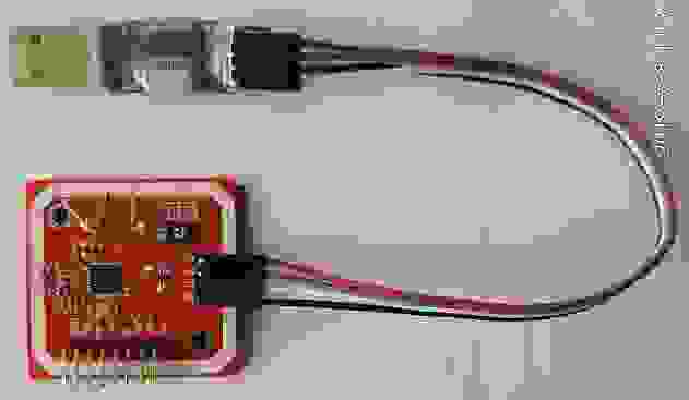
У многих, интересующихся технологией MIfare, наверняка есть простейшее устройство для чтения-записи карт и брелоков Mifare, состоящее из модуля PN532 и USB-UART адаптера:
Путем несложной и недорогой доработки это устройство можно заставить захватывать от
считывателя данные аутентификации, с помощью которых и рассчитываются криптоключи, так необходимые для чтения и копирования. Существуют и серийно выпускаемые приборы для этой цели — SMKey, Proxmark3, Chameleon и ещё некоторые. Это приборы с множеством функций, удобные, но недешевые.
Я предлагаю вашему вниманию более бюджетный вариант на основе подобного «малого джентльменского набора» из модуля PN532 и USB-UART адаптера, позволяющий захватывать данные от считывателя Mifare, например домофона, и рассчитывать криптоключи, с которыми считыватель обращается к метке.
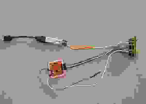
Разработанное устройство в своей основе имеет недорогую, «народную» отладочную плату на основе процессора STM32F103C8T6, прозванную ещё «BluePill» c подключенными к ней модулем PN532 и USB-UART адаптером. Подключается данный агрегат через USB-OTG кабель к смартфону на Андроиде. Собирается всё это в макетном варианте без пайки, с помощью перемычек и имеет примерно такой вид, хоть и непрезентабельный, но вполне рабочий:
Схему сборки очень проста и представлена в текстовом виде:
PN532 ___________________STM32F103C8T6
SCK_____________________PA5(SPI1_SCK)
MISO____________________PA6(SPI1_MISO)
MOSI____________________PA7(SPI1_MOSI)
SS______________________PB0(GPIO_OUTPUT)
SIGIN___________________PB11(TIM2_CH4)
SIGOUT__________________PA12(TIM1_ETR)
SIGOUT__________________PA15(TIM2_ETR)
VCC_____________________+5V
GND_____________________GND
USB-UART________________STM32F103C8T6
RX______________________PA9(USART1_TX)
TX______________________PA10(USART1_RX)
+5V_____________________+5V
GND_____________________GND
ВАЖНО! Переключатели интерфейса PN532 должны быть установлены в режим SPI! Прошить STM32 можно с помощью утилиты FlashLoaderDemonstrator через существующий USB-UART адаптер.
Внимание для работы с новой версией прошивки необходимо изменить схему подключения вывода SIGOUT на PA12 и PA15 (Ранее было на PA0 и PA12)!
Вот демонстрация захвата криптоключа от имитатора считывателя домофона(Arduino + PN532):
Так как считыватели IronLogic(IL), для работы с которыми и разрабатывалось данное устройство, пытаются прочитать метку с криптоключом, рассчитанным на основе UID данной метки, то этот UID сначала надо задать. Сделать это можно двумя способами – вручную или считать с метки. После этого производим захват и ждем расчета криптоключей.
Следующая вкладка программы «Запись на Classic» использует возможность ранних версий считывателей IL записывать копии на дешевые заготовки Mifare Classic. Этот способ основан на том, что считыватель IL после авторизации посылает домофону не оригинальный UID метки, а информацию, записанную в первом блоке (в общем случае совпадающую с UID оригинала). Для этого мы должны захватить и рассчитать криптоключ метки, которая послужит заготовкой, закрыть с его помощью нулевой сектор, а в первый блок этой метки записать четыре байта UID метки, которая служит прототипом. Для этого нам даже не надо захватывать криптоключ оригинала и снимать его дамп, достаточно узнать его UID, но это справедливо только в том случае, если оригинал — «оригинальный», а не является копией, тогда всё-таки придется читать первый блок и уже его записывать в копию. Чтобы было понятнее, рассмотрим такой пример – предположим, что мы хотим сделать копию оригинального ключа с UID 0xEBD52AC5, который записан и в первом блоке оригинала, на обычную метку Mifare Classic с UID, допустим, 0x12345678. Для этого мы с помощью представленного устройства, метко обозванного одним товарищем «Шайтан-Машиной», находим криптоключ именно для этого UID и именно для того объекта (подъезда, дома …), который нам нужен. Пусть криптоключ получился 0xABCDEF098765, тогда отредактируем нулевой сектор дампа копии следущим образом:
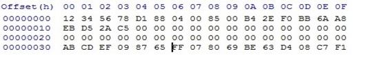
В первый блок запишем UID оригинала 0xEBD52AC5, а в третий блок шесть байт криптоключа, найденного для этой заготовки — 0xABCDEF098765. Запишем дамп в заготовку, и получим копию домофонного ключа. Примерно так прибор SMKey делает копии IronLogic на обычные Mifare Classic, и именно так поступает данная программа записи. В поле «Код» заносим вручную или считываем с оригинального ключа 4 байта UID, которые будут записаны в 1-й блок копии. Стартуем и, далее следуем подсказкам программы. Сначала считываем UID заготовки, потом подносим устройство к домофону и захватываем данные аутентификации. После окончания расчета программа предложит поднести заготовку для записи данных. Если будет найдено более одного криптоключа, то после записи первого варианта будет дана возможность проверить полученную копию. Если копия не подходит, то следует попробовать следующий рассчитанный ключ, или стереть (привести в исходное состояние) заготовку для дальнейшего использования. Копия может не работать также из-за того, что неправильно определили код, который записывается в 1-й блок копии – например если попытаетесь записать реальный UID не оригинального брелока, а его копии, сделанной по вышеописанному методу.В таком случае надо использовать не UID метки, а данные из 1-го блока, которые можно получить в разделе «Копирование сектора».
Этот способ не будет также работать для последних версий ПО считывателей IL. В таком случае копию можно сделать, скопировав полностью 0-й сектор ( 4 блока) на заготовку, позволяющую записывать 0-й блок с помощью раздела приложения «Копирование сектора». Здесь также сначала находим криптоключ оригинала, читаем его нулевой сектор и затем пишем на заготовку. Ввиду отсутствия под рукой заготовок ОТР и ОТР-2.0, эта функция пока тестировалась только на заготовках ZERO, хотя новые версии считывателей требуют использовать ОТР-2.0.
Ну и на закуску – раздел приложения «Запись UID» позволяет изменять UID, восстанавливать испорченный 0-й блок и сбрасывать на дефолт криптоключи заготовок ZERO.
Итак – коротко подытожу. Чтобы сделать такое устройство, приобретаем или ищем по своим загашникам модуль PN532, любой из USB – UART адаптеров FTDI, PL2303, CH340 или CP2102, отладочную плату STM32F103C8T6, полтора десятка перемычек, USB-OTG переходник и смартфон(планшет) на Андроиде с OTG. Собираем по вышеприведенной схеме само устройство, прошиваем *.bin файлом STM32 и устанавливаем *.apk приложение из архива
на смартфон. Для корректной работы приложение на смартфоне должно запускаться при подключении USB-UART адаптера или по умолчанию, или выбором вручную, иначе приложение не получит доступ к адаптеру.
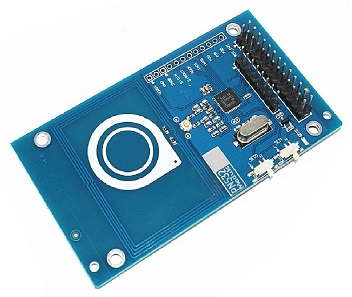
Несколько слов хочу сказать по поводу модуля PN532 – не все эти модули «одинаково полезны»! Из трёх модулей(таких как на фото выше), приобретенных мной, один плохо читал и записывал метки, особенно ZERO и ОТР-2.0, но нормально работал в пассивном режиме со считывателями домофонов, другой вел себя с точностью до наоборот и только третий более-менее справлялся и с метками и с домофонами(правда хуже чем первые два). Возможно мне не повезло и именно эта партия модулей оказалась не лучшего качества, но жалуются на них и другие люди. Впрочем – кому как повезет. Это я к чему говорю? В продаже появились модули PN532 немного другой компоновки, которые дороже, но, по отзывам не имеют таких проблем:
Если же кому-нибудь попадется PN532, который плохо пишет-читает метки, то могу посоветовать добавить к устройству модуль RC522, стоящий сущие копейки, но прекрасно выполняющий свои функции, по следующей схеме:
RC522____________________STM32F103C8T6
RST______________________PB12(GPIO_OUTPUT)
SCK______________________PB13(SPI2_SCK)
MISO_____________________PB14(SPI2_MISO)
MOSI_____________________PB15(SPI2_MOSI)
SDA______________________PA8(GPIO_OUTPUT)
VCC______________________+3.3V
GND______________________GND
В этом случае PN532 будет работать только при захвате данных от считывателя, а вся тяжесть работы с метками ляжет на плечи RC522. Обратите особое внимание — RC522 необходимо подключать на напряжение только 3.3В!
P.S. Обновил ПО устройства — добавилась возможность эмуляции Mifare Classic 1K и создания базы данных меток для нескольких объектов старых домофонов IronLogic. В эмулятор можно загрузить бинарный файл дампа размером 1К, а на вкладке «База меток» можно ввести сколько надо UID-ов пустых заготовок, затем захватить для них криптоключи на различных адресах и потом уже записывать их не выходя к объекту. UID и криптоключ А 0-го сектора записанной метки сохраняется в базе данных, что позволяет при необходимости просто стереть метку, которая была записана на этом устройстве.
UPD. Очередное обновление устройства. Основное — сейчас устройство научилось производить захват и расчет криптоключей от последних версий считывателей IL, вплоть до новых 4-полосных считывателей с последней актуальной прошивкой 7.20 выложенной на сайте!
Еще раз обращаю внимание! Схема подключения модуля PN532 для новой прошивки KeyToolsSTM.bin немного изменена: теперь SIGOUT подключен на PA12 и PA15 контролера STM32, а не на PA12 и PA0, как раньше!
Вместо дорогого и капризного модуля PN532 можно сделать несложную антенну с модулем сопряжения. Схема приведена на рисунке:
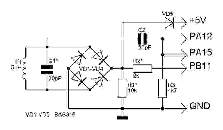
За основу взята статья Простой Mifare-сниффер. Конструкция самой антенны хорошо описана в статье, у меня же неплохо работает бескаркасная катушка диаметром 30мм из 9 витков одножильного изолированного провода, взятого от витой пары интернет кабеля. Прошивка для этой схемы требуется уже другая — KeyTools_WPN.bin. Обратите внимание — такая антенна работает только в пассивном режиме, т.е. только для захвата данных от считки и эмуляции метки. Чтобы читать-записывать метки необходимо дополнить устройство модулем RC522, схема подключения которого приведена выше.
Важное дополнение — вывод PA12 отладочной платы уже подтянут к 3.3В резистором 10кОм, именно исходя из этого выбран номинал R3 = 4к7, но на некоторых платах STM подтягивающий резистор имеет другое сопротивление! Рекомендую замерить сопротивление между РА12 и 3.3В на плате и если оно отличается от 10кОм, то перепаять резистор!
Появилась так же возможность подключения устройства к смартфонам без OTG — для этого вместо USB — UART адаптера подключается Bluetooth модуль типа HC-05, HC-06, а на смартфоне устанавливается приложения KeyToolsBT. Предварительно на Bluetooth модуле с помощью АТ команд необходимо установить скорость обмена 115200! Питание можно организовать от аккумулятора через повышающий преобразователь 5В.
Устройство обсуждается на форуме: Kazus. По всем вопросам обращайтесь туда.
Архив
GitHub
$begingroup$
I’ve bought a PN532 v1.3 breakout board, to which I communicate in SPI.
I can ask it its firmware number, to which it answers D5 03 32 01 06 07 (PN532 V1.6), which is correct.
It can ask it general status, to which it answers D5 05 00 00 00 80, which sounds correct too.
But when I’m trying to use a antenna-related command, it justs freeze here.
For instance, InListPassiveTarget (4A) or InAutoPoll (60) just freeze, meaning the command cannot even be sent correctly.
What I am doing exactly:
- Writing command on the SPI bus
- Waiting for READY status on SPI
- Getting an ACK frame (
00 00 FF 00 FF 00) - Waiting for READY status again. This is where it fails when issing a
4Aor60command. The status never become ready.
Here is the user manual for the chip I’m using: http://www.nxp.com/documents/user_manual/141520.pdf
I don’t understand what am I exaply doing wrong.
asked Nov 8, 2015 at 23:23
$endgroup$
$begingroup$
In my code that communicates with the PN5321A, the inListPassiveTarget function has a time-out in case there is no NFC tag present. I set up an IRQ when I call inAutoPoll and do not wait for any more response after the ACK frame. Are you certain that your hardware is working correctly? The operation you describe is normal for no tag present.
I observed the RF output of my antenna on my oscilloscope with a 15cm loop of wire clipped to the tip of my scope probe and connected to the GND of my scope probe. I put the loop around my NFC antenna and NFC tag (all flat on my desk). I could see the load modulation of the response from my NFC tag when the RF level rises slightly. The bits where the RF signal disappears is when the host is communicating with the target.
answered Dec 14, 2015 at 13:52
MatthewMatthew
4194 silver badges5 bronze badges
$endgroup$
$begingroup$
I’ve bought a PN532 v1.3 breakout board, to which I communicate in SPI.
I can ask it its firmware number, to which it answers D5 03 32 01 06 07 (PN532 V1.6), which is correct.
It can ask it general status, to which it answers D5 05 00 00 00 80, which sounds correct too.
But when I’m trying to use a antenna-related command, it justs freeze here.
For instance, InListPassiveTarget (4A) or InAutoPoll (60) just freeze, meaning the command cannot even be sent correctly.
What I am doing exactly:
- Writing command on the SPI bus
- Waiting for READY status on SPI
- Getting an ACK frame (
00 00 FF 00 FF 00) - Waiting for READY status again. This is where it fails when issing a
4Aor60command. The status never become ready.
Here is the user manual for the chip I’m using: http://www.nxp.com/documents/user_manual/141520.pdf
I don’t understand what am I exaply doing wrong.
asked Nov 8, 2015 at 23:23
$endgroup$
$begingroup$
In my code that communicates with the PN5321A, the inListPassiveTarget function has a time-out in case there is no NFC tag present. I set up an IRQ when I call inAutoPoll and do not wait for any more response after the ACK frame. Are you certain that your hardware is working correctly? The operation you describe is normal for no tag present.
I observed the RF output of my antenna on my oscilloscope with a 15cm loop of wire clipped to the tip of my scope probe and connected to the GND of my scope probe. I put the loop around my NFC antenna and NFC tag (all flat on my desk). I could see the load modulation of the response from my NFC tag when the RF level rises slightly. The bits where the RF signal disappears is when the host is communicating with the target.
answered Dec 14, 2015 at 13:52
MatthewMatthew
4194 silver badges5 bronze badges
$endgroup$
Hi,
I’m playing with pn532 board nad bluepill. For some time, I’ve tried to make it work, but (almost) without success.
From time to time, bluepill is not able to discover pn532, when it happens, I need to unplug 5V from pn532, and then it starts working.
But not for long. After reading card(one on more, depends on luck, not always loop fails right away) it breaks — loop stops executing, green led starts blinking.
Maybe someone had the same problem? I thought it could by caused by writing out of array boundary, but after checking library, everything looks ok.
My configuration:
Pn532 conected to i2c on bluepill(ports b6&b7), powered with 5v from serial programmer. 1k resistor between 5v and SDA and one between 5V and SCL.
My code:
Code: Select all
#include <Wire.h>
#include <PN532_I2C.h>
#include <PN532.h>

PN532_I2C pn532i2c(Wire);
PN532 nfc(pn532i2c);


void setup(void)
{
  Serial.begin(115200);
  nfc.begin();

  uint32_t versiondata = nfc.getFirmwareVersion();
  if (!versiondata)
  {
    Serial.print("Didn't find PN53x board");
    while (1);
  }

  Serial.print("Found chip PN5");
  Serial.println((versiondata >> 24) & 0xFF, HEX);
  Serial.print("Firmware ver. ");
  Serial.print((versiondata >> 16) & 0xFF, DEC);
  Serial.print('.');
  Serial.println((versiondata >> 8) & 0xFF, DEC);

  nfc.setPassiveActivationRetries(0xff);
  nfc.SAMConfig();
}

void loop(void)
{
  bool success;
  uint8_t uid[] = {0, 0, 0, 0, 0, 0, 0};
  uint8_t uidLength;

  success = nfc.readPassiveTargetID(PN532_MIFARE_ISO14443A, &uid[0], &uidLength);

  if (success)
  {
    Serial.println("Found a card!");
    Serial.print("UID Length: ");
    Serial.print(uidLength, DEC);
    Serial.println(" bytes");
    Serial.print("UID Value: ");

    for (uint8_t i = 0; i < uidLength; i++)
    {
      Serial.print(" 0x");
      Serial.print(uid[i], HEX);
     }

    Serial.println("");
    delay(1000);
  }
  else
  {
    Serial.println("Waiting for a card...");
  }
}
I’m using this library: https://github.com/elechouse/PN532
Thanks in advance ![]()
Offline
Зарегистрирован: 10.04.2017
#if 0
  #include <SPI.h>
  #include <PN532_SPI.h>
  #include "PN532.h"

  PN532_SPI pn532spi(SPI, 10);
  PN532 nfc(pn532spi);
#elif 0
  #include <PN532_HSU.h>
  #include <PN532.h>

  PN532_HSU pn532hsu(Serial1);
  PN532 nfc(pn532hsu);
#else
  #include <Wire.h>
  #include <PN532_I2C.h>
  #include <PN532.h>
#endif
void setup(void) {
  Serial.begin(115200);
  Serial.println("Hello!");

  nfc.begin();

  uint32_t versiondata = nfc.getFirmwareVersion();
  if (! versiondata) {
    Serial.print("Didn't find PN53x board");
    while (1); // halt
  }
  // Got ok data, print it out!
  Serial.print("Found chip PN5"); Serial.println((versiondata>>24) & 0xFF, HEX);
  Serial.print("Firmware ver. "); Serial.print((versiondata>>16) & 0xFF, DEC);
  Serial.print('.'); Serial.println((versiondata>>8) & 0xFF, DEC);

  // configure board to read RFID tags
  nfc.SAMConfig();

  Serial.println("Waiting for an ISO14443A Card ...");
}


void loop(void) {
  uint8_t success;
  uint8_t uid[] = { 0, 0, 0, 0, 0, 0, 0 };  // Buffer to store the returned UID
  uint8_t uidLength;                        // Length of the UID (4 or 7 bytes depending on ISO14443A card type)

  // Wait for an ISO14443A type cards (Mifare, etc.).  When one is found
  // 'uid' will be populated with the UID, and uidLength will indicate
  // if the uid is 4 bytes (Mifare Classic) or 7 bytes (Mifare Ultralight)
  success = nfc.readPassiveTargetID(PN532_MIFARE_ISO14443A, uid, &uidLength);

  if (success) {
    // Display some basic information about the card
    Serial.println("Found an ISO14443A card");
    Serial.print("  UID Length: ");Serial.print(uidLength, DEC);Serial.println(" bytes");
    Serial.print("  UID Value: ");
    nfc.PrintHex(uid, uidLength);
    Serial.println("");

    if (uidLength == 4)
    {
      // We probably have a Mifare Classic card ...
      Serial.println("Seems to be a Mifare Classic card (4 byte UID)");

      // Now we need to try to authenticate it for read/write access
      // Try with the factory default KeyA: 0xFF 0xFF 0xFF 0xFF 0xFF 0xFF
      Serial.println("Trying to authenticate block 4 with default KEYA value");
      uint8_t keya[6] = { 0xFF, 0xFF, 0xFF, 0xFF, 0xFF, 0xFF };

	  // Start with block 4 (the first block of sector 1) since sector 0
	  // contains the manufacturer data and it's probably better just
	  // to leave it alone unless you know what you're doing
      success = nfc.mifareclassic_AuthenticateBlock(uid, uidLength, 4, 0, keya);

      if (success)
      {
        Serial.println("Sector 1 (Blocks 4..7) has been authenticated");
        uint8_t data[16];

        // If you want to write something to block 4 to test with, uncomment
		// the following line and this text should be read back in a minute
        // data = { 'a', 'd', 'a', 'f', 'r', 'u', 'i', 't', '.', 'c', 'o', 'm', 0, 0, 0, 0};
        // success = nfc.mifareclassic_WriteDataBlock (4, data);

        // Try to read the contents of block 4
        success = nfc.mifareclassic_ReadDataBlock(4, data);

        if (success)
        {
          // Data seems to have been read ... spit it out
          Serial.println("Reading Block 4:");
          nfc.PrintHexChar(data, 16);
          Serial.println("");

          // Wait a bit before reading the card again
          delay(1000);
        }
        else
        {
          Serial.println("Ooops ... unable to read the requested block.  Try another key?");
        }
      }
      else
      {
        Serial.println("Ooops ... authentication failed: Try another key?");
      }
    }

    if (uidLength == 7)
    {
      // We probably have a Mifare Ultralight card ...
      Serial.println("Seems to be a Mifare Ultralight tag (7 byte UID)");

      // Try to read the first general-purpose user page (#4)
      Serial.println("Reading page 4");
      uint8_t data[32];
      success = nfc.mifareultralight_ReadPage (4, data);
      if (success)
      {
        // Data seems to have been read ... spit it out
        nfc.PrintHexChar(data, 4);
        Serial.println("");

        // Wait a bit before reading the card again
        delay(1000);
      }
      else
      {
        Serial.println("Ooops ... unable to read the requested page!?");
      }
    }
  }
}
ОШИБКА: Arduino: 1.8.4 (Linux), Плата:»Arduino Nano, ATmega328P»
Несколько библиотек найдено для «Wire.h»
Используется: /home/alexdelux/arduino-1.8.4/hardware/arduino/avr/libraries/Wire
Не используется: /home/alexdelux/arduino-1.8.4/libraries/nfcpn532
/tmp/arduino_modified_sketch_120435/readMifare.pde: In function ‘void setup()’:
readMifare:24: error: ‘nfc’ was not declared in this scope
nfc.begin();
^
/tmp/arduino_modified_sketch_120435/readMifare.pde: In function ‘void loop()’:
readMifare:51: error: ‘nfc’ was not declared in this scope
success = nfc.readPassiveTargetID(PN532_MIFARE_ISO14443A, uid, &uidLength);
^
exit status 1
‘nfc’ was not declared in this scope
как решить проблему? должно работать вроде бы без колдовства
На внутренней сети, там не было также введено множество качественных материалов NFC-PN532. Dataset, и руководство развитие не было найдено.
Материал, найденный на крупных форумах и энциклопедии почти все потрогать, или отправить несколько последовательных инструкций порта, или верхний источник библиотеки с открытым исходным кодом привода.
Если вы хотите, чтобы понять, как это используется, это действительно не так просто.
Я кратко некоторые методы использования, и драйвер написан. Конечно, этот модуль имеет много функций, которые только включает в себя чтение и запись на карту.
Следующее применимо только к режиму серийного коммуникационного порта.
1 Общая функция и описание: Последовательный порт по умолчанию 115200
Использование STM32 для управления PN532 чтения и операции записи, функция NFC не читать и писать, я чувствую себя почти почти.
Общая память карты 1K размер, конечно же, есть и другие, не часто.
FUID может только написать UID (не увидеть его в Интернете, нет проверки)
CUID может повторить этот UID (онлайн просмотр, нет проверки)
2 рабочий процесс:

Выше, является полной парой процедур карточки чтения и записи.
Программа также будет осуществляться из этого процесса. Самая основная функция для отправки инструкции к последовательному порту. Конечно, послать команду здесь. Здесь вам необходимо рассчитать проверочное значение и записать его в передней части формулы, а затем передать эту функцию для достижения просыпается , поиск, проверка, чтение и запись.

Вычислить функцию контрольной суммы: Этот Printf используются для тестирования

Каждый водитель первой посылки инструкции, а затем последовательный порт получит команду возврата, а затем разрешить возвращенную инструкцию. Если это успешное обучение, достоверные данные разобран, однако.
Конкретная передача и демонтаж не будут разъяснены, заинтересованы в скачать исходный код, я в основном сказать Колодец и коммуникационные правилам идей и внимания.

Посмотрите на основных функциях: Игнорировать другие файлы, содержание драйвера написано в NFC_PN532, здесь является проверкой третьего сектора, читать содержание.
#include "stm32f10x.h"

#include "led.h"
#include "systick.h"
#include	"serial.h"
#include "24l01.h"
#include "tx_rx_report.h"
#include "1_V4_data.h"
#include "timer.h"
#include "tim3_pwm4.h"

#include "string.h"

#include "NFC_PN532.h"

LED led1('C',13);


int main(void)

{

	u8 uid[4];
	u8 block[16];
	u8 block1[16]={0x16,0x15,0x14,0x13,0x12,0x11,0x10,0x9,0x8,0x7,0x6,0x5,0x4,0x3,0x2,0x1};

	u8 check0[]={0xff,0xff,0xff,0xff,0xff,0xff,0xff,0x7,0x80,0x69,0xff,0xff,0xff,0xff,0xff,0xff};

	u8 check[]={0xff,0xff,0xff,0xff,0xff,0xff};

	u8 check1[]={0x88,0x15,0x14,0x13,0x12,0x11};

	u8 check2[]={0x64,0x98,0x8d,0x22,0x30,0x63};
	u8 i=0;
   u8 n=0;

   Serial1_init (115200); // инициализация последовательного порта 115200

	  Serial3_init (115200); // инициализация последовательного порта 115200

	 Printf (" r  n начать  r  n");


  while(1)
   {


		 PCout(13)=!PCout(13);


		if(awaken_nfc())
		{
			 // printf («Проверьте на устройство NFC  R  n»);
			if(find_card(uid))
			{
				 PrintF («Обнаруженная карта номера:% x% x% x% x  r  n», uid [0], uid [1], uid [2], uid [3]);

				if(check_card(uid,check,11))
				{
					 Printf ("калибровочный успех  r  n");

					block1[0]=0x15;
					n=8;
//					if(write_block(block1,n))
//					{
 // printf («Письменный успех  R  n»);
//					}
//						block1[0]++;
//					if(write_block(block1,n+1))
//					{
 // printf («Письменный успех  R  n»);
//					}
//						block1[0]++;
//					if(write_block(block1,n+2))
//					{
 // printf («Письменный успех  R  n»);
//
//					}


//							block1[0]++;
//					if(write_block(check0,n+3))
//					{
 // printf («Письменный успех  R  n»);
//
//					}


						if(read_block(block,n))
						{
							 Printf («Успешная карта Успех:% D  R  N», N);
							for(i=0;i<16;i++)
							 printf("%x ",block[i]);
							printf("rn");


						}

					if(read_block(block,n+1))
						{
							 Printf ("Успех чтения карты:% d  r  n", n + 1);
							for(i=0;i<16;i++)
							 printf("%x ",block[i]);
							printf("rn");


						}
						if(read_block(block,n+2))
						{
							 PrintF (успешная карта Успех:% d  r  n ", n + 2);
							for(i=0;i<16;i++)
							 printf("%x ",block[i]);
							printf("rn");


						}

						if(read_block(block,n+3))
						{
							 Printf («Успех чтения карты:% d  r  n», n + 3);
							for(i=0;i<16;i++)
							 printf("%x ",block[i]);
							printf("rn");


						}


				}
				else
				{
					 Printf («Проверка не удалась  R  n»);
				}

			}

	}


		 delay_ms(100);

   }


}
Результат:

Исходный код можно подключить к STM32F103C8T6 + PN532
https://download.csdn.net/download/hes_c/11112051
С помощью этого драйвера, вы хотите быть электронная индукция блокировки, и система потребления кредитной карты не является проблемой.
Я хочу, чтобы взломать карты других, конечно, но вы должны знать все методы шифрования друг друга, вы можете написать сканирование, чтобы взломать, это все еще трудно.
Для некоторых карт, которые не зашифрованы, как играть с вами.
Operating environment/Installation (Hass.io/Docker/pip/etc.):
Docker
ESP (ESP32/ESP8266, Board/Sonoff):
Wemos D1 Mini (ESP8266)
ESPHome version (latest production, beta, dev branch)
1.16-dev commit 0059a6d
Affected component:
https://esphome.io/components/binary_sensor/pn532.html
Description of problem:
Since the introduction of i2c support for pn532 the spi communication fails. The following config works before but not after commit esphome/esphome@0059a6d.
Problem-relevant YAML-configuration entries:
spi:
  clk_pin: D5
  miso_pin: D6
  mosi_pin: D7

pn532_spi:
  cs_pin: D4
Logs (if applicable):
�[0;32m[I][app:029]: Running through setup()...�[0m
�[0;35m[C][spi:022]: Setting up SPI bus...�[0m
�[0;32m[I][pn532_spi:015]: PN532Spi setup started!�[0m
�[0;32m[I][pn532_spi:020]: SPI setup finished!�[0m
�[0;35m[C][pn532:027]: Setting up PN532...�[0m
�[1;31m[E][pn532:031]: Error sending version command�[0m
�[1;31m[E][component:092]: Component was marked as failed.�[0m
�[0;32m[I][app:059]: setup() finished successfully!�[0m
�[0;32m[I][app:105]: ESPHome version 1.16.0-dev compiled on Nov 24 2020, 19:50:29�[0m
�[0;35m[C][spi:081]: SPI bus:�[0m
�[0;35m[C][spi:082]:   CLK Pin: GPIO14 (Mode: OUTPUT)�[0m
�[0;35m[C][spi:083]:   MISO Pin: GPIO12 (Mode: INPUT)�[0m
�[0;35m[C][spi:084]:   MOSI Pin: GPIO13 (Mode: OUTPUT)�[0m
�[0;35m[C][spi:085]:   Using HW SPI: YES�[0m
�[0;35m[C][pn532:321]: PN532:�[0m
�[0;35m[C][pn532:333]:   Update Interval: 1.0s�[0m
�[0;35m[C][pn532_spi:065]:   CS Pin: GPIO2 (Mode: OUTPUT)�[0m
I did notice this timeout while running on commit esphome/esphome@22e1758, but tags read correctly:
�[0;32m[I][app:029]: Running through setup()...�[0m
�[0;35m[C][spi:022]: Setting up SPI bus...�[0m
�[0;35m[C][pn532:025]: Setting up PN532...�[0m
�[0;32m[I][app:059]: setup() finished successfully!�[0m
�[1;31m[E][pn532:346]: Timed out waiting for readiness from PN532!�[0m
�[0;33m[W][pn532:103]: Requesting tag read failed!�[0m
�[0;32m[I][app:105]: ESPHome version 1.16.0-dev compiled on Nov 24 2020, 19:54:32�[0m
  ...
 [0;36m[D][pn532:156]: Found new tag '<snip>'�[0m
I see the same log entries on 1.15.3.
Additional information and things you’ve tried:
Also tried latest build (esphome/esphome@7ff3f75), same result.
Hi,
I’m playing with pn532 board nad bluepill. For some time, I’ve tried to make it work, but (almost) without success.
From time to time, bluepill is not able to discover pn532, when it happens, I need to unplug 5V from pn532, and then it starts working.
But not for long. After reading card(one on more, depends on luck, not always loop fails right away) it breaks — loop stops executing, green led starts blinking.
Maybe someone had the same problem? I thought it could by caused by writing out of array boundary, but after checking library, everything looks ok.
My configuration:
Pn532 conected to i2c on bluepill(ports b6&b7), powered with 5v from serial programmer. 1k resistor between 5v and SDA and one between 5V and SCL.
My code:
Code: Select all
#include <Wire.h>
#include <PN532_I2C.h>
#include <PN532.h>

PN532_I2C pn532i2c(Wire);
PN532 nfc(pn532i2c);


void setup(void)
{
  Serial.begin(115200);
  nfc.begin();

  uint32_t versiondata = nfc.getFirmwareVersion();
  if (!versiondata)
  {
    Serial.print("Didn't find PN53x board");
    while (1);
  }

  Serial.print("Found chip PN5");
  Serial.println((versiondata >> 24) & 0xFF, HEX);
  Serial.print("Firmware ver. ");
  Serial.print((versiondata >> 16) & 0xFF, DEC);
  Serial.print('.');
  Serial.println((versiondata >> 8) & 0xFF, DEC);

  nfc.setPassiveActivationRetries(0xff);
  nfc.SAMConfig();
}

void loop(void)
{
  bool success;
  uint8_t uid[] = {0, 0, 0, 0, 0, 0, 0};
  uint8_t uidLength;

  success = nfc.readPassiveTargetID(PN532_MIFARE_ISO14443A, &uid[0], &uidLength);

  if (success)
  {
    Serial.println("Found a card!");
    Serial.print("UID Length: ");
    Serial.print(uidLength, DEC);
    Serial.println(" bytes");
    Serial.print("UID Value: ");

    for (uint8_t i = 0; i < uidLength; i++)
    {
      Serial.print(" 0x");
      Serial.print(uid[i], HEX);
     }

    Serial.println("");
    delay(1000);
  }
  else
  {
    Serial.println("Waiting for a card...");
  }
}
I’m using this library: https://github.com/elechouse/PN532
Thanks in advance ![]()
Loading
Я пытаюсь заставить модуль Pn532 работать на esp32, сначала я попытался заставить его работать с i2c и имел некоторый «успех»(он работал, но как только у меня было другое устройство i2c, в моем случае дисплей, в 90% случаев он отказывался работать), а после в некоторых исследованиях в репо github упоминается, что модуль не работает с несколькими устройствами, подключенными к шине i2c. Теперь я пытаюсь заставить его работать через spi, но он не обнаруживается.
Код: readMirafe пример из библиотеки Adafruit Pn532, но я изменил контакты из строки 42-45
/**************************************************************************/
/*!
    @file     readMifare.pde
    @author   Adafruit Industries
    @license  BSD (see license.txt)
    This example will wait for any ISO14443A card or tag, and
    depending on the size of the UID will attempt to read from it.

    If the card has a 4-byte UID it is probably a Mifare
    Classic card, and the following steps are taken:

    - Authenticate block 4 (the first block of Sector 1) using
      the default KEYA of 0XFF 0XFF 0XFF 0XFF 0XFF 0XFF
    - If authentication succeeds, we can then read any of the
      4 blocks in that sector (though only block 4 is read here)

    If the card has a 7-byte UID it is probably a Mifare
    Ultralight card, and the 4 byte pages can be read directly.
    Page 4 is read by default since this is the first 'general-
    purpose' page on the tags.
This is an example sketch for the Adafruit PN532 NFC/RFID breakout boards
This library works with the Adafruit NFC breakout
  ----> https://www.adafruit.com/products/364

Check out the links above for our tutorials and wiring diagrams
These chips use SPI or I2C to communicate.
Adafruit invests time and resources providing this open source code,
please support Adafruit and open-source hardware by purchasing
products from Adafruit!
*/
/**************************************************************************/
#include <Wire.h>
#include <SPI.h>
#include <Adafruit_PN532.h>

// If using the breakout with SPI, define the pins for SPI communication.
#define PN532_SCK  (18)
#define PN532_MISO (19)
#define PN532_MOSI (23)
#define PN532_SS   (27)

// If using the breakout or shield with I2C, define just the pins connected
// to the IRQ and reset lines.  Use the values below (2, 3) for the shield!
#define PN532_IRQ   (2)
#define PN532_RESET (3)  // Not connected by default on the NFC Shield

// Uncomment just _one_ line below depending on how your breakout or shield
// is connected to the Arduino:

// Use this line for a breakout with a software SPI connection (recommended):
Adafruit_PN532 nfc(PN532_SCK, PN532_MISO, PN532_MOSI, PN532_SS);

// Use this line for a breakout with a hardware SPI connection.  Note that
// the PN532 SCK, MOSI, and MISO pins need to be connected to the Arduino's
// hardware SPI SCK, MOSI, and MISO pins.  On an Arduino Uno these are
// SCK = 13, MOSI = 11, MISO = 12.  The SS line can be any digital IO pin.
//Adafruit_PN532 nfc(PN532_SS);

// Or use this line for a breakout or shield with an I2C connection:
//Adafruit_PN532 nfc(PN532_IRQ, PN532_RESET);


void setup(void) {
  Serial.begin(115200);
  while (!Serial) delay(10); // for Leonardo/Micro/Zero

  Serial.println("Hello!");

  nfc.begin();

  uint32_t versiondata = nfc.getFirmwareVersion();
  if (! versiondata) {
    Serial.print("Didn't find PN53x board");
    while (1); // halt
  }
  // Got ok data, print it out!
  Serial.print("Found chip PN5"); Serial.println((versiondata>>24) & 0xFF, HEX);
  Serial.print("Firmware ver. "); Serial.print((versiondata>>16) & 0xFF, DEC);
  Serial.print('.'); Serial.println((versiondata>>8) & 0xFF, DEC);

  // configure board to read RFID tags
  nfc.SAMConfig();

  Serial.println("Waiting for an ISO14443A Card ...");
}


void loop(void) {
  uint8_t success;
  uint8_t uid[] = { 0, 0, 0, 0, 0, 0, 0 };  // Buffer to store the returned UID
  uint8_t uidLength;                        // Length of the UID (4 or 7 bytes depending on ISO14443A card type)

  // Wait for an ISO14443A type cards (Mifare, etc.).  When one is found
  // 'uid' will be populated with the UID, and uidLength will indicate
  // if the uid is 4 bytes (Mifare Classic) or 7 bytes (Mifare Ultralight)
  success = nfc.readPassiveTargetID(PN532_MIFARE_ISO14443A, uid, &uidLength);

  if (success) {
    // Display some basic information about the card
    Serial.println("Found an ISO14443A card");
    Serial.print("  UID Length: ");Serial.print(uidLength, DEC);Serial.println(" bytes");
    Serial.print("  UID Value: ");
    nfc.PrintHex(uid, uidLength);
    Serial.println("");

    if (uidLength == 4)
    {
      // We probably have a Mifare Classic card ...
      Serial.println("Seems to be a Mifare Classic card (4 byte UID)");

      // Now we need to try to authenticate it for read/write access
      // Try with the factory default KeyA: 0xFF 0xFF 0xFF 0xFF 0xFF 0xFF
      Serial.println("Trying to authenticate block 4 with default KEYA value");
      uint8_t keya[6] = { 0xFF, 0xFF, 0xFF, 0xFF, 0xFF, 0xFF };

      // Start with block 4 (the first block of sector 1) since sector 0
      // contains the manufacturer data and it's probably better just
      // to leave it alone unless you know what you're doing
      success = nfc.mifareclassic_AuthenticateBlock(uid, uidLength, 4, 0, keya);

      if (success)
      {
        Serial.println("Sector 1 (Blocks 4..7) has been authenticated");
        uint8_t data[16];

        // If you want to write something to block 4 to test with, uncomment
        // the following line and this text should be read back in a minute
        //memcpy(data, (const uint8_t[]){ 'a', 'd', 'a', 'f', 'r', 'u', 'i', 't', '.', 'c', 'o', 'm', 0, 0, 0, 0 }, sizeof data);
        // success = nfc.mifareclassic_WriteDataBlock (4, data);

        // Try to read the contents of block 4
        success = nfc.mifareclassic_ReadDataBlock(4, data);

        if (success)
        {
          // Data seems to have been read ... spit it out
          Serial.println("Reading Block 4:");
          nfc.PrintHexChar(data, 16);
          Serial.println("");

          // Wait a bit before reading the card again
          delay(1000);
        }
        else
        {
          Serial.println("Ooops ... unable to read the requested block.  Try another key?");
        }
      }
      else
      {
        Serial.println("Ooops ... authentication failed: Try another key?");
      }
    }

    if (uidLength == 7)
    {
      // We probably have a Mifare Ultralight card ...
      Serial.println("Seems to be a Mifare Ultralight tag (7 byte UID)");

      // Try to read the first general-purpose user page (#4)
      Serial.println("Reading page 4");
      uint8_t data[32];
      success = nfc.mifareultralight_ReadPage (4, data);
      if (success)
      {
        // Data seems to have been read ... spit it out
        nfc.PrintHexChar(data, 4);
        Serial.println("");

        // Wait a bit before reading the card again
        delay(1000);
      }
      else
      {
        Serial.println("Ooops ... unable to read the requested page!?");
      }
    }
  }
}
Моя проводка выглядит следующим образом
(PN523 Module->esp32):
SCK  -> D18;
MSO  -> D19;
MOSI -> D23;
SS   -> D27
И да, плата находится в режиме SPI(dip-переключатель). Спасибо!
I have a PN532 (I2C) connected on a NodeMCU (ESP8266) Everything was working fine. The NFC reader was working.
But as soon as I changed an unused pin GPIO boot state: mode GPIO-13 (D7) to output low the PN532 stopped the PN532 stopped working. In the log file I see read error’s.
When I change the unused pin to default it was working again.
But after some trying, the PN532 stopped working completely. Resetting the PN532, power everything off and on, nothing will help anymore. I also reset the whole EPS8266 to default, but it did not help.
Firmware: 20210802 (Energy) and 20210114 (Energy)
Slow device Clock Speed does not help.
Is this a bug? I’m I doing something wrong?
Error:
507961: PN532: Read error: 124
507961: PN532: Reset on pin: 12
508259: PN532: Read error: 125
508259: PN532: Reset on pin: 12
508561: PN532: Read error: 126
508561: PN532: Reset on pin: 12