In error situation welding is stopped and an error code is displayed on the panel
•
The user can clear the error by pressing any of the panel buttons and if certain conditions are fulfilled
•
If there are multiple errors at the same time only one can be displayed at a time. After user has cleared one error
•
next is displayed and so on until there is no more errors
Error code
Error
2
Mains under voltage
3
Mains over voltage
4
Wire feed motor over current
5
Wire feed motor control not
calibrated
6
Power source control not
calibrated
7
User interface memory error
8
Memory channel 1 error
9
Memory channel 2 error
10
Memory channel 3 error
11
Memory channel 4 error
12
Continuous short circuit in the out-
put of the power source
100
Microcontroller error
101
Microcontroller error
102
Microcontroller error
103
Microcontroller error
110
Panel communication error
111
Panel communication error
112
Panel communication error
Kemppi Oy
SERVICE MANUAL
KEMPACT RA_V_1.2
Reason
-mains voltage is under lower limit.
-181 model: 195 V
-251 model: 204 V
-253, 323 models: 340V
-mains voltage is over high limit:
-181 model: 265 V
-251 model: 276 V
-253, 323 models: 460V
-wire feed motor current (6 amps longer
than 60 s) is too high
-motor is jammed longer than 60 s
-calibration parameters have been corrupted
-faulty control card A001
-power source control calibration parame-
ters are not in predefined limits
-calibration parameters have been corrupted
-faulty control card A001
-EEPROM memory error
-used wrong welding parameters (improper
value)
-memory channel data is invalid / corrupted
-memory channel data is invalid / corrupted
-memory channel data is invalid / corrupted
-memory channel data is invalid / corrupted
-there is continuous (over 2s.) short circuit in
the output of the power source.
-microcontroller reset. Possible reason: tig
ignition spark.
-microcontroller reset. Possible reason:
flash memory has been corrupted
-microcontroller reset. Possible reason: elec-
tromagnetic disturbance
-microcontroller reset. Possible reason: elec-
tromagnetic disturbance
-communication error between panel card
P001 and control card A001
-communication error between panel card
P001 and control card A001
-communication error between panel card
P001 and control card A001
38 (40)
Action / remedy
-check mains voltage
-mains over voltage error can be
cleared after mains voltage has risen
over low limit.
-check mains voltage
-mains over voltage error can be
cleared after mains voltage has fallen
under high limit
-this error can be cleared after weld-
ing has stopped due to this error
-check wire feeding motor and mech-
anism
-start up machine (on/off)
-change control card A001
-start up machine (on/off)
— change control card A001
-start up machine (on/off)
-check welding parameters
-start up machine (on/off)
-check welding parameters
-start up machine (on/off)
-check welding parameters
-start up machine (on/off)
-check welding parameters
-start up machine (on/off)
-check welding parameters
-remove short circuit from machine
output (contact tip is connected /
short circuited in welding piece)
-start up machine (on/off)
-start up machine (on/off)
-start up machine (on/off)
-start up machine (on/off)
-check flat cable/connectors between
panel- and control card
-check flat cable/connectors between
panel- and control card
-check flat cable/connectors between
panel- and control card
Артикул: 6403230
В наличии:
Много

Цена:
310 777 р.
Специальная акция! Возвращаем часть стоимости покупки подарками!
Купить в лизинг
Нашли дешевле?


Краткое описание Kemppi KEMPACT 323R
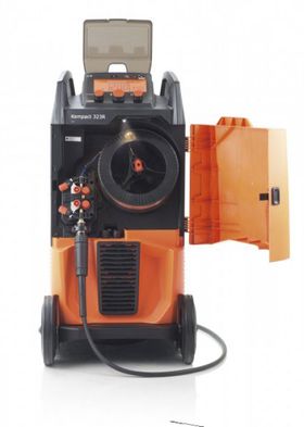
Сварочный полуавтомат KEMPPI Kempact 323R предназначенный для современных сварочных цехов, обладает стильным и практичным дизайном. Высокое качество изготовления, а также функциональные преимущества повышают продуктивность, точность и эффективность сварочных операций. В основу модели Kempact 323R легла последняя разработка источника питания Kemppi, которая гарантирует оптимальные сварочные характеристики и отличную энергоэффективность. Данный аппарат входит в линейку Kempact RA, в которую вошли одиннадцать версий модели включают источники питания с выходным током 180, 250 и 320 ампер и панели управления Regular (R) или Adaptive (A), что охватывает широкий диапазон потребностей цехов металлоконструкций.
Новые технические решения серии включают: снижение потребления электроэнергии более чем на 10 % по сравнению с обычными источниками питания со ступенчатым регулированием, систему освещения корпуса Brights для облегчения загрузки проволоки в условиях слабого освещения, функцию оповещения WireLine для сигнализации о необходимости плановой замены направляющего канала проволоки, а также встроенное шасси GasMate, обеспечивающее удобную и безопасную установку баллона и перемещение аппарата. Какую бы модель вы ни выбрали, аппарат Kempact RA гарантирует максимальную эффективность для любых сварочных операций.
Особенности
- Прочная крышка из оргстекла со смотровым окошком — надежная защита и привлекательный внешний вид.
- Механизм подачи сварочной проволоки с приводом на 4 ролика
- Превосходные сварочные характеристики при использовании в качестве защитного газа как газовых смесей, так и C02
- Точное и чистое зажигание дуги
- Максимальная выходная мощность при рабочем цикле 35%
- Расположение разъема горелки под большим углом улучшает подачу проволоки и срок службы горелки.
- Система освещения корпуса Brights™ в условиях слабого освещения.
- Индикация WireLine™ оповещает о необходимости технического обслуживания системы.
- Встроенные отсеки для хранения деталей привода подачи проволоки и горелки.
- Конструкция шасси GasMate™ обеспечивает удобную и безопасную установку баллона и перемещение аппарата.
- Прочная конструкция из штампованной стали и прессованной пластмассы.
- Простое изменение полярности клемм.
- Пылевой фильтр (дополнительно) для пыльных сварочных цехов.
- Функция термической обработки HotSpot™
- Имеется регулировка индуктивности дуги
- Ролики под проволоку не входят в комплект поставки
Комплект поставки
- Сварочный полуавтомат KEMPPI Kempact 323R
- Кабель заземления 3м с клеммой
- Газовый шланг 1,5м
Характеристики Kemppi KEMPACT 323R
Основные параметры
| Напряжение сети: | 380 В (323-437) |
| MIG/MAG cварочный ток: | 20 — 320 А |
| Сварочное напряжение: | 8-32,5 В |
| Напряжение холостого хода:
?
Напряжение холостого хода (В) – напряжение, подающееся на деталь перед тем, как вы преступите к сварке. Данный параметр влияет на скорость и безопасность возбуждения дуги. Чем выше его значение, тем быстрее и легче происходит возбуждение дуги, но больше опасность поражения электрическим током. |
46 В |
| Мощность при максимальной нагрузке, кВт | 12 кВт |
| Длина горелки: | 3.50 м |
Дополнительные параметры
| Класс защиты:
? Степень защиты (IP). Этот параметр указывает на степень защищенности сварочного аппарата от воздействия внешних факторов. Чем выше это значение, тем устройство надежней и его можно использовать практически в любых условиях при повышенной влажности или запыленности. |
IP23S |
| Коэффициент мощности (COS?):
? Коэффициент мощности (сos φ). Этот параметр указывает на отношение активной мощности сварочного аппарата к его полной составляющей мощности. Чем ближе коэффициент мощности к значению 1, тем больше потребляемой электроэнергии будет уходить на выполнение работы и меньше на дополнительные нагрузки на электросеть. К примеру, при cos ф – 0,93 (7 % — реактивная мощность, 93 % — активная полезная мощность). |
0.94 |
| КПД:
? Коэффициент полезного действия КПД (%). Чем ближе данное значение к 100 %, тем более эффективно будет работать сварочный аппарат, поскольку больше потребляемой электроэнергии будет уходить на выполнение работы и меньше тратиться вхолостую. |
86 |
| Потребляемая мощность:
? Потребляемая мощность (кВа). Параметр, от которого зависит расход электроэнергии при осуществлении работ и, соответственно, ее стоимость. |
12 кВА |
| Артикул: | 6403230 |
| Габаритные размеры:
? Габаритные размеры (мм). Габаритные размеры определяют компактность и мобильность устройства. Соответственно, чем они меньше, тем меньше места будет занимать сварочный аппарат, и тем удобней будет с ним передвигаться при работе. |
623x579x1070 |
| Вес:
? Вес (кг). Вес сварочного аппарата часто определяет работы, которые с его помощью можно выполнять. Если легкие аппараты можно переносить с места на место (некоторые из них оснащены ремнями для ношения на плече), то более тяжелые модели требуют стационарного расположения. При этом некоторые модели тяжелых аппаратов оснащаются колесами для более удобной транспортировки и пультами дистанционного регулирования сварочных параметров. |
44 кг. |
| Номинальное напряжение: | 46 В |
| Скорость подачи проволоки (min — max): | 1-20 мм/сек |
| Сетевой предохранитель: | 10 |
| Потребляемый ток:
? Потребляемый ток (А). От этого параметра зависят требования к питающей электросети при осуществлении сварочных работ. К примеру, при сварке электродом диаметром 3 мм потребляемый ток составляет 15-20 А, но уже при сварке электродом диаметром 4 мм этот параметр возрастает до 25-30 А. Поэтому если у вас стоит автомат защиты на 20 А, а потребляемый ток аппарата значительно выше, автомат может выбить во время сварки. |
8.20 А |
| Сечение кабеля: | 1.50 мм |
| Длина кабеля:
? Длина кабеля питания (м). Чем длиннее кабель питания сварочного аппарата, тем на большем расстоянии от доступа к электрической сети можно осуществлять работы и тем удобнее будет использовать устройство. |
5 |
| Страна производства: | Финляндия |
| Гарантийный срок:
? Срок службы (лет). Данный параметр указывает на гарантированный период эксплуатации устройства, который подтвержден заводом изготовителем. |
2 |
*Внимание: описание и характеристики товара носят информационный характер и могут отличаться от представленных в технической документации производителя. Убедительно просим Вас при покупке проверять наличие желаемых функций и характеристик.
Оцените работу этого аппарата в нашем демо-зале
Чтобы принять взвешенное решение о покупке, лучше сравнить разные
модели оборудования в работе. Приезжайте в наш демонстрационный зал и у Вас будет такая
возможность.
Подробнее про запись на демонстрацию
оборудования
Почему купить Kemppi KEMPACT 323R нужно именно у нас?
- Бесплатная доставка Kemppi KEMPACT 323R в любой город России.
- Дополнительно +1 год полной гарантии на Kemppi в подарок.
- Подарок, который вы выбираете сами.
- Для юр.лиц — полный комплект документов. Торг-12 + Счет-фактура. Стоимость оборудования указана с НДС.
- Лучшие цены которые Вы можете найти
Сертификаты и учредительные документы
Аналоги сварочного полуавтомата Kemppi KEMPACT 323R
Отзывы о инверторном полуавтомате Kemppi KEMPACT 323R
Станьте первым, кто оставит отзыв на Kemppi KEMPACT 323R
Доставка осуществляется в указанные ниже и еще более 500 городов России. Подробные условия
по ссылке

-
Contents
-
Table of Contents
-
Bookmarks
Quick Links
SERVICE MANUAL
KEMPACT RA
181A
251R/251A
253R/253A
323R/323A
253MV/323MV
Kemppi Oy
Related Manuals for Kemppi Kempact 253R
Summary of Contents for Kemppi Kempact 253R
- Page 1
SERVICE MANUAL KEMPACT RA 181A 251R/251A 253R/253A 323R/323A 253MV/323MV Kemppi Oy… -
Page 2: Table Of Contents
3.4.2.1. EMC filter …………………………….18 3.4.2.2. Inrush current limiting …………………………18 3.4.2.3. IGBT driver …………………………….. 18 3.4.2.4. Current transformer T1 …………………………. 18 3.4.2.5. Main circuit ……………………………. 18 3.4.2.6. PFC Boost control circuitry ……………………….18 4. MAIN CIRCUIT CARD Z001 …………………………….19 Kemppi Oy…
- Page 3
Digital multimeters may give different values depending the specifications they have. For example diode measuring values may vary between the multimeters models. Special attention must be considered while working with the internal parts. The device may be repaired only by a person legally authorized to perform electrical work. Kemppi Oy… -
Page 4: Service Manual
SERVICE MANUAL 3 (40) KEMPACT RA_V_1.2 1. PARTS OF MACHINE Kempact RA (253, 323) Kemppi Oy…
- Page 5
SERVICE MANUAL 4 (40) KEMPACT RA_V_1.2 Kempact RA (253, 323) NOTE ! spareparts@kemppi.com Spare part info available from: (email). Kemppi Oy… -
Page 6: Technical Information
EMC class Degree of protection IP23S IP23S Operating temperature range -20…+40 °C -20…+40 °C Storage temperature range -40…+60 °C -40…+60 °C Standards IEC 60974-1 IEC 60974-1 IEC 60974-5 IEC 60974-5 IEC 60974-10 IEC 60974-10 IEC 61000-3-12 IEC 61000-3-12 Kemppi Oy…
- Page 7
SERVICE MANUAL 6 (40) KEMPACT RA_V_1.2 Kempact 253R, 253A Kempact 323R, 323A Connection voltage 50/60Hz 400V+- 15% 3~ 50/60Hz 400V +- 15% 3~ Rated power at max. current 40% ED I1max (250A) 8.34kVA/7.73kW 35% ED I1max (320A) 12kVA/11.3kW Supply current 40% ED I1max (250A) 11.9A… - Page 8
623x579x1070 mm LxWxH 623x579x1070 mm Not including gun and Not including gun and Weight gables 44 kg gables 44 kg Temperature class F(155 C) F(155 C) EMC class Degree of protection IP23S IP23S Operating temperature -20…+40 °C -20…+40 °C Kemppi Oy… - Page 9
SERVICE MANUAL 8 (40) KEMPACT RA_V_1.2 range Storage temperature range -40…+60 °C -40…+60 °C Standards IEC 60974-1 IEC 60974-1 IEC 60974-5 IEC 60974-5 IEC 60974-10 IEC 60974-10 IEC 61000-3-12 IEC 61000-3-12 Kemppi Oy… -
Page 10: Main Circuit Diagrams
SERVICE MANUAL 9 (40) KEMPACT RA_V_1.2 2.2. Main circuit diagrams Kemppi Oy…
- Page 11
SERVICE MANUAL 10 (40) KEMPACT RA_V_1.2 Kemppi Oy… - Page 12
SERVICE MANUAL 11 (40) KEMPACT RA_V_1.2 * Please refer to Kemppi Channel for the latest version of main circuit drawings ! Kemppi Oy… - Page 13
Wire feed motor M003 • Brights led card P002 • Panel card P001 • Main circuit card Z001 • Secondary rectifier card Z002 • Secondary choke L001 • Output RFI filters C001 and C002 • Euro connector X005 • Kemppi Oy… -
Page 14: Main Components
The microcontroller also regulates wire feed speed by setting motor current reference and measuring EMF of the • motor 3.1.8.3. Motor control Wire feed motor control is based on EMF (electro magnetic force) measurement principle • Kemppi Oy…
-
Page 15: Fans M001, M002
Capacitors C1 and C2 and resistors R3 and R4 form a snubber circuit. The snubber circuit reduces the voltage stress of • the diodes caused by the reverse recovery current snap off Varistors R1 and R2 are for TIG ignition spark protection • Kemppi Oy…
-
Page 16: Secondary Choke L001
The switching frequency of the boost circuit is ca. 15 kHz. The boost circuit raises DC link voltage to ca. 370V. Boost • input current is measured using shunt resistors R58, R59, R65, R66. H – bridge is implemented using the other two legs of the IGBT module Kemppi Oy…
-
Page 17: Pfc Boost Control Circuitry
When IGBT-transistors G1 and G4 conduct, there is a positive voltage U in main transformer T1 primary and when IGBT- transistors G2 and G3 conduct there is a negative voltage U in main transformer primary. Power is adjusted by changing the Kemppi Oy IGBT timings (PWM).
- Page 18
SERVICE MANUAL 17 (40) KEMPACT RA_V_1.2 Kemppi Oy… -
Page 19: Main Circuit Diagram 253Mv-, 323Mv-Models
PFC control circuitry is located on the primary side. Auxliary transformer T003 supplies operating voltage for the PFC • control circuitry. The output voltage of the T003 is first rectified and then linear regulator is used to regulate auxiliary voltage to 15V. PFC control IC N1 regulates DC-link voltage to approximately 630V. Kemppi Oy…
-
Page 20: Connectors
Main voltage connector Mains voltage Mains voltage connector Signal Chassis ground connector Signal Auxiliary transformer connection, auxliary transformer is protected with PTC resistors R63 and R64 PFC Auxiliary transformer connection, auxliary transformer is protected with PTC resistors R63 and R64 Kemppi Oy…
- Page 21
Other end of the IGBT driver transformer primary X10:11 PFC ON/OFF N PFC on/off opto coupler diode negative end X10:12 Signal PFC choke connections PFC choke connections PFC choke connections PFC choke connections Signal DC-link voltage DC-link voltage Kemppi Oy… -
Page 22: Kempact 253, 323
Auxiliary transformer connection, auxliary transformer is protected with PTC resistors R16 and R17 Signal Main transformer connections (253 machine use two flat connectors, 323 use four) Main transformer connections (253 machine use two flat connectors, 323 use four) Kemppi Oy…
- Page 23
IGBT Drive A Other end of the IGBT driver transformer primary X9:5 OV Opto N Over voltage optocoupler other end X9:6 Inrush Relay Other end of the inrush relay coil Signal Primary current transformer connector Signal DC-link voltage DC-link voltage Kemppi Oy… -
Page 24: Kempact 253Mv, 323Mv
X3, X22 Mains voltage Mains voltage connector Signal Chassis ground connection Signal Description Auxliary transformer connectors. Auxliary transformer is protected with PTC resistors R63 and R64. Auxliary transformer connectors. Auxliary transformer is protected with PTC resistors R63 and R64. Kemppi Oy…
- Page 25
Over voltage optocoupler other end X18:4 IGBT Drive A Other end of the IGBT driver transformer primary X18:5 PFC ON/OFF N PFC on/off opto coupler diode positive end X18:6 OV Opto N Over voltage optocoupler other end Signal DC-link voltage DC-link voltage Kemppi Oy… -
Page 26: Secondary Rectifier Card Z002
SERVICE MANUAL 25 (40) KEMPACT RA_V_1.2 5. SECONDARY RECTIFIER CARD Z002 5.1. Connectors Signal Main transformer secondary Main transformer secondary Z002 card connection to secondary profile Z002 card connection to secondary profile Rectified +24V Polarity connector (-) Kemppi Oy…
-
Page 27: Control Card A001
Signal Description X2:1 + 50 V Secondary voltage from secondary card X2:2 Ground X2:3 + 24 V +24V from the auxiliary transformer X2:4 Motor (+) Wire feed motor (+) X2:5 Motor (-) Wire feed motor (-) X2:6 Ground Kemppi Oy…
- Page 28
IGBT driver transformer other end X6:5 PTC connection X6:6 Start A Gun switch connection Signal Connections to chassis ground Signal Used in development purposes, do not connect anything here Signal Maintenance use Signal Panel card P001 connection Signal Not in use Kemppi Oy… -
Page 29: Panel Card P001
Pulse potentiometer 2 channel A X1:11 Pot_2_B Pulse potentiometer 2 channel B X1:12 Ground X1:13 Pot_3_A Pulse potentiometer 3 channel A X1:14 Pot_3_B Pulse potentiometer 3 channel B X1:15 +5V supply voltage X1:16 +24V +24V supply voltage for the LCD backlight Kemppi Oy…
-
Page 30: Kempact 181, 251
Result: 0,3…0,6 diodes Ok 4) Positive pole to rectifier pole (4, red), negative test pole to rectifier poles (1, black) one at the time Result: no value diodes Ok NOTE ! The measurement procedure is same for V24 and V25 rectifiers. Kemppi Oy…
-
Page 31: Igbt Module V1
1) Positive test pole (1, red) to connector X16, negative test pole (1, black) to connectors X7, X8 and X14 one at time Result: 0,3…0,6 diodes Ok 2) Negative test pole (2, black) to connector X13, positive test pole (2, red) to connectors and X7, X8 and X14 one at time Result: 0,3…0,6 diodes Ok Kemppi Oy…
-
Page 32: Kempact 253, 323
3) Negative test pole to DC-link (+), positive test pole L1, L2, L3 (one at the time) Result: 0,3…0,6 diodes Ok 4) Negative test pole to DC-link (-), positive test pole L1, L2, L3 (one at the time) Result: no value diodes Ok Kemppi Oy…
-
Page 33: Igbt Module, V2
1) Positive test pole to connector X7 and X8 one at time, negative test pole to DC link (+) Result: 0,3…0,6 diodes Ok 2) Positive test pole to DC-link (-), negative test pole to X7 and X8 one at time Result: 0,3…0,6 diodes Ok Kemppi Oy…
-
Page 34: Kempact 253Mv, 323Mv
3) Positive test pole to rectifier pole (2, red), negative test pole rectifier poles (2, black)one at the time Result: 0,3…0,6 diodes Ok 4) Negative test pole to rectifier pole (3, black), positive test pole to rectifier poles (2, red) one at the time Result: no value diodes Ok Kemppi Oy…
-
Page 35: Igbt Module, V1
1) Negative test pole (1, black) to connector X19, positive test pole (1, red) to connectors X13, X14 and X17 one at time Result: 0,3…0,6 diodes Ok 2) Positive test pole (2, red) to connector X20, negative test pole (2, black) to connectors and X13, X14 and X17 one at time Result: 0,3…0,6 diodes Ok Kemppi Oy…
- Page 36
1) Positive test pole to main transformer secondary (secondary card connectors X1 and X2 one at time), negative test pole to secondary profile Result: 0,3…0,6 diodes Ok 2) Positive test pole to secondary profile, negative test pole to main transformer secondary (secondary card connectors X1 and X2 one at time) Result: no value diodes Ok Kemppi Oy… -
Page 37: Ptc’s, Overheat Protection
Primary rectifier V1 to heatsink 2 NM • IGBT unit to heatsink • First step 2 NM and wait a couple minutes Second step 3 NM Main circuit card Z001 to profile holder 0,7 NM • Primary unit to component frame 2 NM • Kemppi Oy…
-
Page 38: Secondary Rectifier Card Z002
• Auxiliary transformer T002 to component frame 5 NM • Secondary choke L001 to component frame 2 NM • Secondary choke L001 other lead to secondary profile 5 NM and other lead to polarity screw 5 NM • Kemppi Oy…
-
Page 39: Error Codes
-communication error between panel card -check flat cable/connectors between P001 and control card A001 panel- and control card Panel communication error -communication error between panel card -check flat cable/connectors between P001 and control card A001 panel- and control card Kemppi Oy…
-
Contents
-
Table of Contents
-
Bookmarks
Quick Links
SERVICE MANUAL
KEMPACT RA
181A
251R/251A
253R/253A
323R/323A
253MV/323MV
Kemppi Oy
Related Manuals for Kemppi Kempact 253R
Summary of Contents for Kemppi Kempact 253R
- Page 1
SERVICE MANUAL KEMPACT RA 181A 251R/251A 253R/253A 323R/323A 253MV/323MV Kemppi Oy… -
Page 2: Table Of Contents
3.4.2.1. EMC filter …………………………….18 3.4.2.2. Inrush current limiting …………………………18 3.4.2.3. IGBT driver …………………………….. 18 3.4.2.4. Current transformer T1 …………………………. 18 3.4.2.5. Main circuit ……………………………. 18 3.4.2.6. PFC Boost control circuitry ……………………….18 4. MAIN CIRCUIT CARD Z001 …………………………….19 Kemppi Oy…
- Page 3
Digital multimeters may give different values depending the specifications they have. For example diode measuring values may vary between the multimeters models. Special attention must be considered while working with the internal parts. The device may be repaired only by a person legally authorized to perform electrical work. Kemppi Oy… -
Page 4: Service Manual
SERVICE MANUAL 3 (40) KEMPACT RA_V_1.2 1. PARTS OF MACHINE Kempact RA (253, 323) Kemppi Oy…
- Page 5
SERVICE MANUAL 4 (40) KEMPACT RA_V_1.2 Kempact RA (253, 323) NOTE ! spareparts@kemppi.com Spare part info available from: (email). Kemppi Oy… -
Page 6: Technical Information
EMC class Degree of protection IP23S IP23S Operating temperature range -20…+40 °C -20…+40 °C Storage temperature range -40…+60 °C -40…+60 °C Standards IEC 60974-1 IEC 60974-1 IEC 60974-5 IEC 60974-5 IEC 60974-10 IEC 60974-10 IEC 61000-3-12 IEC 61000-3-12 Kemppi Oy…
- Page 7
SERVICE MANUAL 6 (40) KEMPACT RA_V_1.2 Kempact 253R, 253A Kempact 323R, 323A Connection voltage 50/60Hz 400V+- 15% 3~ 50/60Hz 400V +- 15% 3~ Rated power at max. current 40% ED I1max (250A) 8.34kVA/7.73kW 35% ED I1max (320A) 12kVA/11.3kW Supply current 40% ED I1max (250A) 11.9A… - Page 8
623x579x1070 mm LxWxH 623x579x1070 mm Not including gun and Not including gun and Weight gables 44 kg gables 44 kg Temperature class F(155 C) F(155 C) EMC class Degree of protection IP23S IP23S Operating temperature -20…+40 °C -20…+40 °C Kemppi Oy… - Page 9
SERVICE MANUAL 8 (40) KEMPACT RA_V_1.2 range Storage temperature range -40…+60 °C -40…+60 °C Standards IEC 60974-1 IEC 60974-1 IEC 60974-5 IEC 60974-5 IEC 60974-10 IEC 60974-10 IEC 61000-3-12 IEC 61000-3-12 Kemppi Oy… -
Page 10: Main Circuit Diagrams
SERVICE MANUAL 9 (40) KEMPACT RA_V_1.2 2.2. Main circuit diagrams Kemppi Oy…
- Page 11
SERVICE MANUAL 10 (40) KEMPACT RA_V_1.2 Kemppi Oy… - Page 12
SERVICE MANUAL 11 (40) KEMPACT RA_V_1.2 * Please refer to Kemppi Channel for the latest version of main circuit drawings ! Kemppi Oy… - Page 13
Wire feed motor M003 • Brights led card P002 • Panel card P001 • Main circuit card Z001 • Secondary rectifier card Z002 • Secondary choke L001 • Output RFI filters C001 and C002 • Euro connector X005 • Kemppi Oy… -
Page 14: Main Components
The microcontroller also regulates wire feed speed by setting motor current reference and measuring EMF of the • motor 3.1.8.3. Motor control Wire feed motor control is based on EMF (electro magnetic force) measurement principle • Kemppi Oy…
-
Page 15: Fans M001, M002
Capacitors C1 and C2 and resistors R3 and R4 form a snubber circuit. The snubber circuit reduces the voltage stress of • the diodes caused by the reverse recovery current snap off Varistors R1 and R2 are for TIG ignition spark protection • Kemppi Oy…
-
Page 16: Secondary Choke L001
The switching frequency of the boost circuit is ca. 15 kHz. The boost circuit raises DC link voltage to ca. 370V. Boost • input current is measured using shunt resistors R58, R59, R65, R66. H – bridge is implemented using the other two legs of the IGBT module Kemppi Oy…
-
Page 17: Pfc Boost Control Circuitry
When IGBT-transistors G1 and G4 conduct, there is a positive voltage U in main transformer T1 primary and when IGBT- transistors G2 and G3 conduct there is a negative voltage U in main transformer primary. Power is adjusted by changing the Kemppi Oy IGBT timings (PWM).
- Page 18
SERVICE MANUAL 17 (40) KEMPACT RA_V_1.2 Kemppi Oy… -
Page 19: Main Circuit Diagram 253Mv-, 323Mv-Models
PFC control circuitry is located on the primary side. Auxliary transformer T003 supplies operating voltage for the PFC • control circuitry. The output voltage of the T003 is first rectified and then linear regulator is used to regulate auxiliary voltage to 15V. PFC control IC N1 regulates DC-link voltage to approximately 630V. Kemppi Oy…
-
Page 20: Connectors
Main voltage connector Mains voltage Mains voltage connector Signal Chassis ground connector Signal Auxiliary transformer connection, auxliary transformer is protected with PTC resistors R63 and R64 PFC Auxiliary transformer connection, auxliary transformer is protected with PTC resistors R63 and R64 Kemppi Oy…
- Page 21
Other end of the IGBT driver transformer primary X10:11 PFC ON/OFF N PFC on/off opto coupler diode negative end X10:12 Signal PFC choke connections PFC choke connections PFC choke connections PFC choke connections Signal DC-link voltage DC-link voltage Kemppi Oy… -
Page 22: Kempact 253, 323
Auxiliary transformer connection, auxliary transformer is protected with PTC resistors R16 and R17 Signal Main transformer connections (253 machine use two flat connectors, 323 use four) Main transformer connections (253 machine use two flat connectors, 323 use four) Kemppi Oy…
- Page 23
IGBT Drive A Other end of the IGBT driver transformer primary X9:5 OV Opto N Over voltage optocoupler other end X9:6 Inrush Relay Other end of the inrush relay coil Signal Primary current transformer connector Signal DC-link voltage DC-link voltage Kemppi Oy… -
Page 24: Kempact 253Mv, 323Mv
X3, X22 Mains voltage Mains voltage connector Signal Chassis ground connection Signal Description Auxliary transformer connectors. Auxliary transformer is protected with PTC resistors R63 and R64. Auxliary transformer connectors. Auxliary transformer is protected with PTC resistors R63 and R64. Kemppi Oy…
- Page 25
Over voltage optocoupler other end X18:4 IGBT Drive A Other end of the IGBT driver transformer primary X18:5 PFC ON/OFF N PFC on/off opto coupler diode positive end X18:6 OV Opto N Over voltage optocoupler other end Signal DC-link voltage DC-link voltage Kemppi Oy… -
Page 26: Secondary Rectifier Card Z002
SERVICE MANUAL 25 (40) KEMPACT RA_V_1.2 5. SECONDARY RECTIFIER CARD Z002 5.1. Connectors Signal Main transformer secondary Main transformer secondary Z002 card connection to secondary profile Z002 card connection to secondary profile Rectified +24V Polarity connector (-) Kemppi Oy…
-
Page 27: Control Card A001
Signal Description X2:1 + 50 V Secondary voltage from secondary card X2:2 Ground X2:3 + 24 V +24V from the auxiliary transformer X2:4 Motor (+) Wire feed motor (+) X2:5 Motor (-) Wire feed motor (-) X2:6 Ground Kemppi Oy…
- Page 28
IGBT driver transformer other end X6:5 PTC connection X6:6 Start A Gun switch connection Signal Connections to chassis ground Signal Used in development purposes, do not connect anything here Signal Maintenance use Signal Panel card P001 connection Signal Not in use Kemppi Oy… -
Page 29: Panel Card P001
Pulse potentiometer 2 channel A X1:11 Pot_2_B Pulse potentiometer 2 channel B X1:12 Ground X1:13 Pot_3_A Pulse potentiometer 3 channel A X1:14 Pot_3_B Pulse potentiometer 3 channel B X1:15 +5V supply voltage X1:16 +24V +24V supply voltage for the LCD backlight Kemppi Oy…
-
Page 30: Kempact 181, 251
Result: 0,3…0,6 diodes Ok 4) Positive pole to rectifier pole (4, red), negative test pole to rectifier poles (1, black) one at the time Result: no value diodes Ok NOTE ! The measurement procedure is same for V24 and V25 rectifiers. Kemppi Oy…
-
Page 31: Igbt Module V1
1) Positive test pole (1, red) to connector X16, negative test pole (1, black) to connectors X7, X8 and X14 one at time Result: 0,3…0,6 diodes Ok 2) Negative test pole (2, black) to connector X13, positive test pole (2, red) to connectors and X7, X8 and X14 one at time Result: 0,3…0,6 diodes Ok Kemppi Oy…
-
Page 32: Kempact 253, 323
3) Negative test pole to DC-link (+), positive test pole L1, L2, L3 (one at the time) Result: 0,3…0,6 diodes Ok 4) Negative test pole to DC-link (-), positive test pole L1, L2, L3 (one at the time) Result: no value diodes Ok Kemppi Oy…
-
Page 33: Igbt Module, V2
1) Positive test pole to connector X7 and X8 one at time, negative test pole to DC link (+) Result: 0,3…0,6 diodes Ok 2) Positive test pole to DC-link (-), negative test pole to X7 and X8 one at time Result: 0,3…0,6 diodes Ok Kemppi Oy…
-
Page 34: Kempact 253Mv, 323Mv
3) Positive test pole to rectifier pole (2, red), negative test pole rectifier poles (2, black)one at the time Result: 0,3…0,6 diodes Ok 4) Negative test pole to rectifier pole (3, black), positive test pole to rectifier poles (2, red) one at the time Result: no value diodes Ok Kemppi Oy…
-
Page 35: Igbt Module, V1
1) Negative test pole (1, black) to connector X19, positive test pole (1, red) to connectors X13, X14 and X17 one at time Result: 0,3…0,6 diodes Ok 2) Positive test pole (2, red) to connector X20, negative test pole (2, black) to connectors and X13, X14 and X17 one at time Result: 0,3…0,6 diodes Ok Kemppi Oy…
- Page 36
1) Positive test pole to main transformer secondary (secondary card connectors X1 and X2 one at time), negative test pole to secondary profile Result: 0,3…0,6 diodes Ok 2) Positive test pole to secondary profile, negative test pole to main transformer secondary (secondary card connectors X1 and X2 one at time) Result: no value diodes Ok Kemppi Oy… -
Page 37: Ptc’s, Overheat Protection
Primary rectifier V1 to heatsink 2 NM • IGBT unit to heatsink • First step 2 NM and wait a couple minutes Second step 3 NM Main circuit card Z001 to profile holder 0,7 NM • Primary unit to component frame 2 NM • Kemppi Oy…
-
Page 38: Secondary Rectifier Card Z002
• Auxiliary transformer T002 to component frame 5 NM • Secondary choke L001 to component frame 2 NM • Secondary choke L001 other lead to secondary profile 5 NM and other lead to polarity screw 5 NM • Kemppi Oy…
-
Page 39: Error Codes
-communication error between panel card -check flat cable/connectors between P001 and control card A001 panel- and control card Panel communication error -communication error between panel card -check flat cable/connectors between P001 and control card A001 panel- and control card Kemppi Oy…
- Manuals
- Brands
- Kemppi Manuals
- Welding System
- KEMPACT 323A
Manuals and User Guides for Kemppi KEMPACT 323A. We have 4 Kemppi KEMPACT 323A manuals available for free PDF download: Operating Manual, Service Manual, Quick Manual

Kemppi KEMPACT 323A Operating Manual (42 pages)
Kempact Welding machine
Brand: Kemppi
|
Category: Welding System
|
Size: 5.11 MB
Table of Contents
-
-
Positioning and Location of the Machine
6
-
3 Machine Introduction
8
-
General View of the Machine
8
-
-
4 Before You Start Using the Unit
12
-
Installing Filler Wire
12
-
Mounting and Locking of Filler Wire Spool
12
-
Setting the Spool Brake Force
13
-
Loading the Welding Wire to Feed Mechanism
13
-
Setting the Pressure of the Feed Rolls
15
-
Wire Guide Tubes and Feed Rolls
16
-
Changing the Feed Rolls
18
-
-
4.9.1 Dusty Work Environments
19
-
-
-
5 Using Control Panels
20
-
Adaptive Control Panel
22
-
-
Disposal of the Machine
36
Advertisement

Kemppi KEMPACT 323A Service Manual (40 pages)
KEMPACT RA series
Brand: Kemppi
|
Category: Welding System
|
Size: 4.38 MB
Table of Contents
-
1 Parts of Machine
6
-
2 Technical Information
6
-
-
PFC Boost Control Circuitry
17
-
Main Circuit Diagram 253MV-, 323MV-Models
19
-
Main Circuit Card Z001
20
-
-
5 Secondary Rectifier Card Z002
26
-
8 Operational Measurings and Tests
30
-
Primary Rectifier V24, 25
30
-
-
Primary Rectifier, V31
34
-
-
Ptc’s, Overheat Protection
37
-
-
9 Main Components Installation
37
-
Main Circuit Card Z001
37
-
Secondary Rectifier Card Z002
38
-

Kemppi KEMPACT 323A Quick Manual (13 pages)
Brand: Kemppi
|
Category: Welding System
|
Size: 4.24 MB
Advertisement

Kemppi KEMPACT 323A Quick Manual (13 pages)
Brand: Kemppi
|
Category: Welding System
|
Size: 4.11 MB
Advertisement
Related Products
-
Kemppi KEMPACT 323R
-
Kemppi Kempact 323RMV
-
Kemppi Kempact 323AMV
-
Kemppi Kempact 323 MV
-
Kemppi KEMPOWELD 3200W
-
Kemppi 32
-
Kemppi MasterTig 325DC G
-
Kemppi MasterTig 325DC
-
Kemppi MasterTig 325DC GM
-
Kemppi Pro Evolution 3200 MVU
Kemppi Categories
Welding System
Welding Accessories
Motorcycle Accessories
Safety Equipment
Water Filtration Systems
More Kemppi Manuals
- Manuals
- Brands
- Kemppi Manuals
- Welding System
- KEMPACT 323A
Manuals and User Guides for Kemppi KEMPACT 323A. We have 4 Kemppi KEMPACT 323A manuals available for free PDF download: Operating Manual, Service Manual, Quick Manual
Kemppi KEMPACT 323A Operating Manual (42 pages)
Kempact Welding machine
Brand: Kemppi
|
Category: Welding System
|
Size: 5.11 MB
Table of Contents
-
-
Positioning and Location of the Machine
6
-
3 Machine Introduction
8
-
General View of the Machine
8
-
-
4 Before You Start Using the Unit
12
-
Installing Filler Wire
12
-
Mounting and Locking of Filler Wire Spool
12
-
Setting the Spool Brake Force
13
-
Loading the Welding Wire to Feed Mechanism
13
-
Setting the Pressure of the Feed Rolls
15
-
Wire Guide Tubes and Feed Rolls
16
-
Changing the Feed Rolls
18
-
-
4.9.1 Dusty Work Environments
19
-
-
-
5 Using Control Panels
20
-
Adaptive Control Panel
22
-
-
Disposal of the Machine
36
Advertisement
Kemppi KEMPACT 323A Service Manual (40 pages)
KEMPACT RA series
Brand: Kemppi
|
Category: Welding System
|
Size: 4.38 MB
Table of Contents
-
1 Parts of Machine
6
-
2 Technical Information
6
-
-
PFC Boost Control Circuitry
17
-
Main Circuit Diagram 253MV-, 323MV-Models
19
-
Main Circuit Card Z001
20
-
-
5 Secondary Rectifier Card Z002
26
-
8 Operational Measurings and Tests
30
-
Primary Rectifier V24, 25
30
-
-
Primary Rectifier, V31
34
-
-
Ptc’s, Overheat Protection
37
-
-
9 Main Components Installation
37
-
Main Circuit Card Z001
37
-
Secondary Rectifier Card Z002
38
-
Kemppi KEMPACT 323A Quick Manual (13 pages)
Brand: Kemppi
|
Category: Welding System
|
Size: 4.24 MB
Advertisement
Kemppi KEMPACT 323A Quick Manual (13 pages)
Brand: Kemppi
|
Category: Welding System
|
Size: 4.11 MB
Advertisement
Related Products
-
Kemppi KEMPACT 323R
-
Kemppi Kempact 323RMV
-
Kemppi Kempact 323AMV
-
Kemppi Kempact 323 MV
-
Kemppi KEMPOWELD 3200W
-
Kemppi 32
-
Kemppi MasterTig 325DC G
-
Kemppi MasterTig 325DC
-
Kemppi MasterTig 325DC GM
-
Kemppi Pro Evolution 3200 MVU
Kemppi Categories
Welding System
Welding Accessories
Motorcycle Accessories
Safety Equipment
Water Filtration Systems
More Kemppi Manuals
Силовой источник 1…..50
Логика MIG 51…..100
Доступ Кривой 101…..130
Интерфейс Робота 131…..150
MIG/TIG Устройство 151…..200
Интерфейс пользавателя 201…..250
Другие 0…..999
Err 2: Силовой источник под напряжением (новый пуск)
Err 3: Силовое исходное перенапряжение (новый пуск)
Err 4: Силовой источник перегрет.
Err 5: Водяная тревога устройства.
Err 11: Два устройства имеют тот же адрес на системной шине.
Err 12: Ошибка данных на связи (2)
Err 13: *Цензура* неправильного семейства FastMIG связанного.
Err 14: Проблема связи Данных между силовым источником и вспомогательным устройством.
Err 15: Силовая исходная программа / обновление метода проблемы.
Err 21: Силовая исходная управляющая карта +5 aux V. Напряжение слишком низкий уровень.
Err 22: Силовая исходная управляющая карта +15 aux V. Напряжение слишком низкий уровень.
Err 23: Временно силовое исходное перенапряжение.
Err 31: Силовая исходная ошибка калибровки. Сваривать только возможно со значением по умолчанию.
Err 54: Нет связи с источником питания. Возможно неисправный кабель/разъем..
Err 55: Сварка запрещена(конфигурация / системной шине резервирована)
Err 61: Нет связи с водоохладителем..
Err 153: Перегрев холодной жидкости сварочного рукава.
Err 154: Двигатель подачи проволоки перегружен выше предела.
Возможно засорена спираль или сильний изгиб сварочного рукава.
Err 155: Перегрузка двигателя подачи проволоки. Движение (ток) двигателя слишком близкое к пределу.
Err 161: Предупреждение перегрева устройства проволочной подачи.
Err 162: Перегрузка двигателя подачи проволоки.
Err 171: Конфигурация оборудования не может обнаружится.
Err 172: Поставлен неправильный код конфигурации.
Err 173: Действие не активизировано кодом конфигурации права
Err 184: Неисправен управляющий кабель.
Err 185: Машинная программная ошибка коррекции. Неправильная программа или обновить коррекцию.
Err 201: Использование сварочного рукава PMT-предохраненного.
Err 221: Ошибка данных панели (1)
Err 222: Ошибка данных панели (2)
Err 223: Ошибка данных панели (3)
Err 224: Ошибка данных панели (4)
Err 225: Запрограммируйте обновление проблемы.
Err 241: Ошыбка памяти EEPROM
Err 251: Ошибка связи данных DLI (другое устройство в шине использует то же код=конфигурацию)
Err 251: Ошибка (2) данных DLI
Err 254: Ошибка связи данных DLI ( плохой разъем или кабель)
Err 255: Ошибка связи данных DLI
(программная проблема коррекции, может быть неправильная программная версия и т.п.).
Err 999: Неопознанная ошибка (система послала сообщение ошибки не идентифицированное панелью)
Источник: https://krb1-elektrik.narod.ru
In error situation welding is stopped and an error code is displayed on the panel
•
The user can clear the error by pressing any of the panel buttons and if certain conditions are fulfilled
•
If there are multiple errors at the same time only one can be displayed at a time. After user has cleared one error
•
next is displayed and so on until there is no more errors
Error code
Error
2
Mains under voltage
3
Mains over voltage
4
Wire feed motor over current
5
Wire feed motor control not
calibrated
6
Power source control not
calibrated
7
User interface memory error
8
Memory channel 1 error
9
Memory channel 2 error
10
Memory channel 3 error
11
Memory channel 4 error
12
Continuous short circuit in the out-
put of the power source
100
Microcontroller error
101
Microcontroller error
102
Microcontroller error
103
Microcontroller error
110
Panel communication error
111
Panel communication error
112
Panel communication error
Kemppi Oy
SERVICE MANUAL
KEMPACT RA_V_1.2
Reason
-mains voltage is under lower limit.
-181 model: 195 V
-251 model: 204 V
-253, 323 models: 340V
-mains voltage is over high limit:
-181 model: 265 V
-251 model: 276 V
-253, 323 models: 460V
-wire feed motor current (6 amps longer
than 60 s) is too high
-motor is jammed longer than 60 s
-calibration parameters have been corrupted
-faulty control card A001
-power source control calibration parame-
ters are not in predefined limits
-calibration parameters have been corrupted
-faulty control card A001
-EEPROM memory error
-used wrong welding parameters (improper
value)
-memory channel data is invalid / corrupted
-memory channel data is invalid / corrupted
-memory channel data is invalid / corrupted
-memory channel data is invalid / corrupted
-there is continuous (over 2s.) short circuit in
the output of the power source.
-microcontroller reset. Possible reason: tig
ignition spark.
-microcontroller reset. Possible reason:
flash memory has been corrupted
-microcontroller reset. Possible reason: elec-
tromagnetic disturbance
-microcontroller reset. Possible reason: elec-
tromagnetic disturbance
-communication error between panel card
P001 and control card A001
-communication error between panel card
P001 and control card A001
-communication error between panel card
P001 and control card A001
38 (40)
Action / remedy
-check mains voltage
-mains over voltage error can be
cleared after mains voltage has risen
over low limit.
-check mains voltage
-mains over voltage error can be
cleared after mains voltage has fallen
under high limit
-this error can be cleared after weld-
ing has stopped due to this error
-check wire feeding motor and mech-
anism
-start up machine (on/off)
-change control card A001
-start up machine (on/off)
— change control card A001
-start up machine (on/off)
-check welding parameters
-start up machine (on/off)
-check welding parameters
-start up machine (on/off)
-check welding parameters
-start up machine (on/off)
-check welding parameters
-start up machine (on/off)
-check welding parameters
-remove short circuit from machine
output (contact tip is connected /
short circuited in welding piece)
-start up machine (on/off)
-start up machine (on/off)
-start up machine (on/off)
-start up machine (on/off)
-check flat cable/connectors between
panel- and control card
-check flat cable/connectors between
panel- and control card
-check flat cable/connectors between
panel- and control card
3.
КОДЫ ОШИБОК FASTMIG
Наличие возможных неисправностей в оборудовании оценивается при каждом запуске
механизма подачи проволоки. В случае обнаружения неисправности она будет указываться в
виде сообщения об ошибке на дисплее панели.
Примеры кодов ошибок:
Err 2: Пониженное напряжение
Устройство остановилось, поскольку было обнаружено понижение напряжения в сети,
оказывающее влияние на процесс сварки. Проверьте качество сети электропитания.
Err 3: Повышенное напряжение
Работа оборудования остановлена, так как в электрической сети был обнаружен временный
опасный бросок напряжения или постоянное превышение напряжения. Проверьте качество
сети электропитания.
Err 4: Перегрев источника питания
Источник питания перегрелся. Перегрев может быть вызван одной из следующих причин:
• источник питания длительное время работал на максимальной мощности;
• перекрыта подача охлаждающего воздуха к источнику питания;
• неисправность в системе охлаждения.
Удалите препятствия на пути циркуляции воздуха и подождите, пока вентилятор источника
питания не охладит аппарат.
Err 5: Аварийная сигнализация водоохладителя
Заблокирована циркуляция воды. Перегрев может быть вызван одной из следующих причин:
• закупоривание или отсоединение трубопровода охлаждения;
• недостаточное количество охлаждающей жидкости;
• превышение температуры охлаждающей жидкости.
Проверьте циркуляцию охлаждающей жидкости и циркуляцию воздуха через
водоохладитель.
Err 54: Отсутствует обмен данными с источником питания
Передача данных между источником питания и механизмом подачи проволоки прервана или
осуществляется с ошибками. Проверьте удлинительный кабель и соединения.
Err 55: Источник питания занят
Канал связи занят. Источник питания используется другим механизмом подачи проволоки
или по каналу связи выполняется программирование для другого устройства (например,
панели управления).
Err 61: Водоохладитель не обнаружен
Водоохладитель не подсоединен к оборудованию или соединение неисправно.
Подключите водоохладитель или, если используется сварочная горелка с воздушным
охлаждением, измените настройки аппарата на воздушное охлаждение.
Err 153: Перегрев горелки PMT с жидкостным охлаждением
В начале или во время сварки произошло включение системы предотвращения перегрева
сварочной горелки MIG с жидкостным охлаждением. Убедитесь, что в блоке охлаждения
находится достаточное количество жидкости и что воздух свободно циркулирует через блок
RU RU
охлаждения. Убедитесь, что жидкость свободно циркулирует через шланги охлаждения.
Err 154: Перегрузка электродвигателя устройства подачи проволоки
Сварка была прервана, поскольку нагрузка на электродвигатель подачи проволоки возросла
до высокого уровня. Причиной такого повышения может быть засорение направляющего
канала. Проверьте канал проволоки, контактный наконечник и подающие валики.
Err 155: Предупреждающий сигнал о перегрузке механизма подачи проволоки
Уровень нагрузки электродвигателя устройства подачи проволоки возрос. Причиной
такого повышения может быть загрязнение канала проволоки или резкие перегибы кабеля
горелки. В случае необходимости проверьте состояние сварочной горелки и прочистите
направляющий канал.
Err 165: Предупреждение предохранительного устройства регулировки газа
Сработало предохранительное устройство регулировки газа, поскольку давление газа
снизилось. Возможные причины: Газ не подается к механизму подачи проволоки. Запас
газа исчерпан, течь в шланге защитного газа или низкое давление в сети защитного газа.
18
FastMig MS 200, MS 300
-
Contents
-
Table of Contents
-
Bookmarks
Quick Links
SERVICE MANUAL
KEMPACT RA
181A
251R/251A
253R/253A
323R/323A
253MV/323MV
Kemppi Oy
Related Manuals for Kemppi Kempact 253R
Summary of Contents for Kemppi Kempact 253R
-
Page 1
SERVICE MANUAL KEMPACT RA 181A 251R/251A 253R/253A 323R/323A 253MV/323MV Kemppi Oy… -
Page 2: Table Of Contents
3.4.2.1. EMC filter …………………………….18 3.4.2.2. Inrush current limiting …………………………18 3.4.2.3. IGBT driver …………………………….. 18 3.4.2.4. Current transformer T1 …………………………. 18 3.4.2.5. Main circuit ……………………………. 18 3.4.2.6. PFC Boost control circuitry ……………………….18 4. MAIN CIRCUIT CARD Z001 …………………………….19 Kemppi Oy…
-
Page 3
Digital multimeters may give different values depending the specifications they have. For example diode measuring values may vary between the multimeters models. Special attention must be considered while working with the internal parts. The device may be repaired only by a person legally authorized to perform electrical work. Kemppi Oy… -
Page 4: Service Manual
SERVICE MANUAL 3 (40) KEMPACT RA_V_1.2 1. PARTS OF MACHINE Kempact RA (253, 323) Kemppi Oy…
-
Page 5
SERVICE MANUAL 4 (40) KEMPACT RA_V_1.2 Kempact RA (253, 323) NOTE ! spareparts@kemppi.com Spare part info available from: (email). Kemppi Oy… -
Page 6: Technical Information
EMC class Degree of protection IP23S IP23S Operating temperature range -20…+40 °C -20…+40 °C Storage temperature range -40…+60 °C -40…+60 °C Standards IEC 60974-1 IEC 60974-1 IEC 60974-5 IEC 60974-5 IEC 60974-10 IEC 60974-10 IEC 61000-3-12 IEC 61000-3-12 Kemppi Oy…
-
Page 7
SERVICE MANUAL 6 (40) KEMPACT RA_V_1.2 Kempact 253R, 253A Kempact 323R, 323A Connection voltage 50/60Hz 400V+- 15% 3~ 50/60Hz 400V +- 15% 3~ Rated power at max. current 40% ED I1max (250A) 8.34kVA/7.73kW 35% ED I1max (320A) 12kVA/11.3kW Supply current 40% ED I1max (250A) 11.9A… -
Page 8
623x579x1070 mm LxWxH 623x579x1070 mm Not including gun and Not including gun and Weight gables 44 kg gables 44 kg Temperature class F(155 C) F(155 C) EMC class Degree of protection IP23S IP23S Operating temperature -20…+40 °C -20…+40 °C Kemppi Oy… -
Page 9
SERVICE MANUAL 8 (40) KEMPACT RA_V_1.2 range Storage temperature range -40…+60 °C -40…+60 °C Standards IEC 60974-1 IEC 60974-1 IEC 60974-5 IEC 60974-5 IEC 60974-10 IEC 60974-10 IEC 61000-3-12 IEC 61000-3-12 Kemppi Oy… -
Page 10: Main Circuit Diagrams
SERVICE MANUAL 9 (40) KEMPACT RA_V_1.2 2.2. Main circuit diagrams Kemppi Oy…
-
Page 11
SERVICE MANUAL 10 (40) KEMPACT RA_V_1.2 Kemppi Oy… -
Page 12
SERVICE MANUAL 11 (40) KEMPACT RA_V_1.2 * Please refer to Kemppi Channel for the latest version of main circuit drawings ! Kemppi Oy… -
Page 13
Wire feed motor M003 • Brights led card P002 • Panel card P001 • Main circuit card Z001 • Secondary rectifier card Z002 • Secondary choke L001 • Output RFI filters C001 and C002 • Euro connector X005 • Kemppi Oy… -
Page 14: Main Components
The microcontroller also regulates wire feed speed by setting motor current reference and measuring EMF of the • motor 3.1.8.3. Motor control Wire feed motor control is based on EMF (electro magnetic force) measurement principle • Kemppi Oy…
-
Page 15: Fans M001, M002
Capacitors C1 and C2 and resistors R3 and R4 form a snubber circuit. The snubber circuit reduces the voltage stress of • the diodes caused by the reverse recovery current snap off Varistors R1 and R2 are for TIG ignition spark protection • Kemppi Oy…
-
Page 16: Secondary Choke L001
The switching frequency of the boost circuit is ca. 15 kHz. The boost circuit raises DC link voltage to ca. 370V. Boost • input current is measured using shunt resistors R58, R59, R65, R66. H – bridge is implemented using the other two legs of the IGBT module Kemppi Oy…
-
Page 17: Pfc Boost Control Circuitry
When IGBT-transistors G1 and G4 conduct, there is a positive voltage U in main transformer T1 primary and when IGBT- transistors G2 and G3 conduct there is a negative voltage U in main transformer primary. Power is adjusted by changing the Kemppi Oy IGBT timings (PWM).
-
Page 18
SERVICE MANUAL 17 (40) KEMPACT RA_V_1.2 Kemppi Oy… -
Page 19: Main Circuit Diagram 253Mv-, 323Mv-Models
PFC control circuitry is located on the primary side. Auxliary transformer T003 supplies operating voltage for the PFC • control circuitry. The output voltage of the T003 is first rectified and then linear regulator is used to regulate auxiliary voltage to 15V. PFC control IC N1 regulates DC-link voltage to approximately 630V. Kemppi Oy…
-
Page 20: Connectors
Main voltage connector Mains voltage Mains voltage connector Signal Chassis ground connector Signal Auxiliary transformer connection, auxliary transformer is protected with PTC resistors R63 and R64 PFC Auxiliary transformer connection, auxliary transformer is protected with PTC resistors R63 and R64 Kemppi Oy…
-
Page 21
Other end of the IGBT driver transformer primary X10:11 PFC ON/OFF N PFC on/off opto coupler diode negative end X10:12 Signal PFC choke connections PFC choke connections PFC choke connections PFC choke connections Signal DC-link voltage DC-link voltage Kemppi Oy… -
Page 22: Kempact 253, 323
Auxiliary transformer connection, auxliary transformer is protected with PTC resistors R16 and R17 Signal Main transformer connections (253 machine use two flat connectors, 323 use four) Main transformer connections (253 machine use two flat connectors, 323 use four) Kemppi Oy…
-
Page 23
IGBT Drive A Other end of the IGBT driver transformer primary X9:5 OV Opto N Over voltage optocoupler other end X9:6 Inrush Relay Other end of the inrush relay coil Signal Primary current transformer connector Signal DC-link voltage DC-link voltage Kemppi Oy… -
Page 24: Kempact 253Mv, 323Mv
X3, X22 Mains voltage Mains voltage connector Signal Chassis ground connection Signal Description Auxliary transformer connectors. Auxliary transformer is protected with PTC resistors R63 and R64. Auxliary transformer connectors. Auxliary transformer is protected with PTC resistors R63 and R64. Kemppi Oy…
-
Page 25
Over voltage optocoupler other end X18:4 IGBT Drive A Other end of the IGBT driver transformer primary X18:5 PFC ON/OFF N PFC on/off opto coupler diode positive end X18:6 OV Opto N Over voltage optocoupler other end Signal DC-link voltage DC-link voltage Kemppi Oy… -
Page 26: Secondary Rectifier Card Z002
SERVICE MANUAL 25 (40) KEMPACT RA_V_1.2 5. SECONDARY RECTIFIER CARD Z002 5.1. Connectors Signal Main transformer secondary Main transformer secondary Z002 card connection to secondary profile Z002 card connection to secondary profile Rectified +24V Polarity connector (-) Kemppi Oy…
-
Page 27: Control Card A001
Signal Description X2:1 + 50 V Secondary voltage from secondary card X2:2 Ground X2:3 + 24 V +24V from the auxiliary transformer X2:4 Motor (+) Wire feed motor (+) X2:5 Motor (-) Wire feed motor (-) X2:6 Ground Kemppi Oy…
-
Page 28
IGBT driver transformer other end X6:5 PTC connection X6:6 Start A Gun switch connection Signal Connections to chassis ground Signal Used in development purposes, do not connect anything here Signal Maintenance use Signal Panel card P001 connection Signal Not in use Kemppi Oy… -
Page 29: Panel Card P001
Pulse potentiometer 2 channel A X1:11 Pot_2_B Pulse potentiometer 2 channel B X1:12 Ground X1:13 Pot_3_A Pulse potentiometer 3 channel A X1:14 Pot_3_B Pulse potentiometer 3 channel B X1:15 +5V supply voltage X1:16 +24V +24V supply voltage for the LCD backlight Kemppi Oy…
-
Page 30: Kempact 181, 251
Result: 0,3…0,6 diodes Ok 4) Positive pole to rectifier pole (4, red), negative test pole to rectifier poles (1, black) one at the time Result: no value diodes Ok NOTE ! The measurement procedure is same for V24 and V25 rectifiers. Kemppi Oy…
-
Page 31: Igbt Module V1
1) Positive test pole (1, red) to connector X16, negative test pole (1, black) to connectors X7, X8 and X14 one at time Result: 0,3…0,6 diodes Ok 2) Negative test pole (2, black) to connector X13, positive test pole (2, red) to connectors and X7, X8 and X14 one at time Result: 0,3…0,6 diodes Ok Kemppi Oy…
-
Page 32: Kempact 253, 323
3) Negative test pole to DC-link (+), positive test pole L1, L2, L3 (one at the time) Result: 0,3…0,6 diodes Ok 4) Negative test pole to DC-link (-), positive test pole L1, L2, L3 (one at the time) Result: no value diodes Ok Kemppi Oy…
-
Page 33: Igbt Module, V2
1) Positive test pole to connector X7 and X8 one at time, negative test pole to DC link (+) Result: 0,3…0,6 diodes Ok 2) Positive test pole to DC-link (-), negative test pole to X7 and X8 one at time Result: 0,3…0,6 diodes Ok Kemppi Oy…
-
Page 34: Kempact 253Mv, 323Mv
3) Positive test pole to rectifier pole (2, red), negative test pole rectifier poles (2, black)one at the time Result: 0,3…0,6 diodes Ok 4) Negative test pole to rectifier pole (3, black), positive test pole to rectifier poles (2, red) one at the time Result: no value diodes Ok Kemppi Oy…
-
Page 35: Igbt Module, V1
1) Negative test pole (1, black) to connector X19, positive test pole (1, red) to connectors X13, X14 and X17 one at time Result: 0,3…0,6 diodes Ok 2) Positive test pole (2, red) to connector X20, negative test pole (2, black) to connectors and X13, X14 and X17 one at time Result: 0,3…0,6 diodes Ok Kemppi Oy…
-
Page 36
1) Positive test pole to main transformer secondary (secondary card connectors X1 and X2 one at time), negative test pole to secondary profile Result: 0,3…0,6 diodes Ok 2) Positive test pole to secondary profile, negative test pole to main transformer secondary (secondary card connectors X1 and X2 one at time) Result: no value diodes Ok Kemppi Oy… -
Page 37: Ptc’s, Overheat Protection
Primary rectifier V1 to heatsink 2 NM • IGBT unit to heatsink • First step 2 NM and wait a couple minutes Second step 3 NM Main circuit card Z001 to profile holder 0,7 NM • Primary unit to component frame 2 NM • Kemppi Oy…
-
Page 38: Secondary Rectifier Card Z002
• Auxiliary transformer T002 to component frame 5 NM • Secondary choke L001 to component frame 2 NM • Secondary choke L001 other lead to secondary profile 5 NM and other lead to polarity screw 5 NM • Kemppi Oy…
-
Page 39: Error Codes
-communication error between panel card -check flat cable/connectors between P001 and control card A001 panel- and control card Panel communication error -communication error between panel card -check flat cable/connectors between P001 and control card A001 panel- and control card Kemppi Oy…
-
Contents
-
Table of Contents
-
Bookmarks
Quick Links
SERVICE MANUAL
KEMPACT RA
181A
251R/251A
253R/253A
323R/323A
253MV/323MV
Kemppi Oy
Related Manuals for Kemppi Kempact 253R
Summary of Contents for Kemppi Kempact 253R
-
Page 1
SERVICE MANUAL KEMPACT RA 181A 251R/251A 253R/253A 323R/323A 253MV/323MV Kemppi Oy… -
Page 2: Table Of Contents
3.4.2.1. EMC filter …………………………….18 3.4.2.2. Inrush current limiting …………………………18 3.4.2.3. IGBT driver …………………………….. 18 3.4.2.4. Current transformer T1 …………………………. 18 3.4.2.5. Main circuit ……………………………. 18 3.4.2.6. PFC Boost control circuitry ……………………….18 4. MAIN CIRCUIT CARD Z001 …………………………….19 Kemppi Oy…
-
Page 3
Digital multimeters may give different values depending the specifications they have. For example diode measuring values may vary between the multimeters models. Special attention must be considered while working with the internal parts. The device may be repaired only by a person legally authorized to perform electrical work. Kemppi Oy… -
Page 4: Service Manual
SERVICE MANUAL 3 (40) KEMPACT RA_V_1.2 1. PARTS OF MACHINE Kempact RA (253, 323) Kemppi Oy…
-
Page 5
SERVICE MANUAL 4 (40) KEMPACT RA_V_1.2 Kempact RA (253, 323) NOTE ! spareparts@kemppi.com Spare part info available from: (email). Kemppi Oy… -
Page 6: Technical Information
EMC class Degree of protection IP23S IP23S Operating temperature range -20…+40 °C -20…+40 °C Storage temperature range -40…+60 °C -40…+60 °C Standards IEC 60974-1 IEC 60974-1 IEC 60974-5 IEC 60974-5 IEC 60974-10 IEC 60974-10 IEC 61000-3-12 IEC 61000-3-12 Kemppi Oy…
-
Page 7
SERVICE MANUAL 6 (40) KEMPACT RA_V_1.2 Kempact 253R, 253A Kempact 323R, 323A Connection voltage 50/60Hz 400V+- 15% 3~ 50/60Hz 400V +- 15% 3~ Rated power at max. current 40% ED I1max (250A) 8.34kVA/7.73kW 35% ED I1max (320A) 12kVA/11.3kW Supply current 40% ED I1max (250A) 11.9A… -
Page 8
623x579x1070 mm LxWxH 623x579x1070 mm Not including gun and Not including gun and Weight gables 44 kg gables 44 kg Temperature class F(155 C) F(155 C) EMC class Degree of protection IP23S IP23S Operating temperature -20…+40 °C -20…+40 °C Kemppi Oy… -
Page 9
SERVICE MANUAL 8 (40) KEMPACT RA_V_1.2 range Storage temperature range -40…+60 °C -40…+60 °C Standards IEC 60974-1 IEC 60974-1 IEC 60974-5 IEC 60974-5 IEC 60974-10 IEC 60974-10 IEC 61000-3-12 IEC 61000-3-12 Kemppi Oy… -
Page 10: Main Circuit Diagrams
SERVICE MANUAL 9 (40) KEMPACT RA_V_1.2 2.2. Main circuit diagrams Kemppi Oy…
-
Page 11
SERVICE MANUAL 10 (40) KEMPACT RA_V_1.2 Kemppi Oy… -
Page 12
SERVICE MANUAL 11 (40) KEMPACT RA_V_1.2 * Please refer to Kemppi Channel for the latest version of main circuit drawings ! Kemppi Oy… -
Page 13
Wire feed motor M003 • Brights led card P002 • Panel card P001 • Main circuit card Z001 • Secondary rectifier card Z002 • Secondary choke L001 • Output RFI filters C001 and C002 • Euro connector X005 • Kemppi Oy… -
Page 14: Main Components
The microcontroller also regulates wire feed speed by setting motor current reference and measuring EMF of the • motor 3.1.8.3. Motor control Wire feed motor control is based on EMF (electro magnetic force) measurement principle • Kemppi Oy…
-
Page 15: Fans M001, M002
Capacitors C1 and C2 and resistors R3 and R4 form a snubber circuit. The snubber circuit reduces the voltage stress of • the diodes caused by the reverse recovery current snap off Varistors R1 and R2 are for TIG ignition spark protection • Kemppi Oy…
-
Page 16: Secondary Choke L001
The switching frequency of the boost circuit is ca. 15 kHz. The boost circuit raises DC link voltage to ca. 370V. Boost • input current is measured using shunt resistors R58, R59, R65, R66. H – bridge is implemented using the other two legs of the IGBT module Kemppi Oy…
-
Page 17: Pfc Boost Control Circuitry
When IGBT-transistors G1 and G4 conduct, there is a positive voltage U in main transformer T1 primary and when IGBT- transistors G2 and G3 conduct there is a negative voltage U in main transformer primary. Power is adjusted by changing the Kemppi Oy IGBT timings (PWM).
-
Page 18
SERVICE MANUAL 17 (40) KEMPACT RA_V_1.2 Kemppi Oy… -
Page 19: Main Circuit Diagram 253Mv-, 323Mv-Models
PFC control circuitry is located on the primary side. Auxliary transformer T003 supplies operating voltage for the PFC • control circuitry. The output voltage of the T003 is first rectified and then linear regulator is used to regulate auxiliary voltage to 15V. PFC control IC N1 regulates DC-link voltage to approximately 630V. Kemppi Oy…
-
Page 20: Connectors
Main voltage connector Mains voltage Mains voltage connector Signal Chassis ground connector Signal Auxiliary transformer connection, auxliary transformer is protected with PTC resistors R63 and R64 PFC Auxiliary transformer connection, auxliary transformer is protected with PTC resistors R63 and R64 Kemppi Oy…
-
Page 21
Other end of the IGBT driver transformer primary X10:11 PFC ON/OFF N PFC on/off opto coupler diode negative end X10:12 Signal PFC choke connections PFC choke connections PFC choke connections PFC choke connections Signal DC-link voltage DC-link voltage Kemppi Oy… -
Page 22: Kempact 253, 323
Auxiliary transformer connection, auxliary transformer is protected with PTC resistors R16 and R17 Signal Main transformer connections (253 machine use two flat connectors, 323 use four) Main transformer connections (253 machine use two flat connectors, 323 use four) Kemppi Oy…
-
Page 23
IGBT Drive A Other end of the IGBT driver transformer primary X9:5 OV Opto N Over voltage optocoupler other end X9:6 Inrush Relay Other end of the inrush relay coil Signal Primary current transformer connector Signal DC-link voltage DC-link voltage Kemppi Oy… -
Page 24: Kempact 253Mv, 323Mv
X3, X22 Mains voltage Mains voltage connector Signal Chassis ground connection Signal Description Auxliary transformer connectors. Auxliary transformer is protected with PTC resistors R63 and R64. Auxliary transformer connectors. Auxliary transformer is protected with PTC resistors R63 and R64. Kemppi Oy…
-
Page 25
Over voltage optocoupler other end X18:4 IGBT Drive A Other end of the IGBT driver transformer primary X18:5 PFC ON/OFF N PFC on/off opto coupler diode positive end X18:6 OV Opto N Over voltage optocoupler other end Signal DC-link voltage DC-link voltage Kemppi Oy… -
Page 26: Secondary Rectifier Card Z002
SERVICE MANUAL 25 (40) KEMPACT RA_V_1.2 5. SECONDARY RECTIFIER CARD Z002 5.1. Connectors Signal Main transformer secondary Main transformer secondary Z002 card connection to secondary profile Z002 card connection to secondary profile Rectified +24V Polarity connector (-) Kemppi Oy…
-
Page 27: Control Card A001
Signal Description X2:1 + 50 V Secondary voltage from secondary card X2:2 Ground X2:3 + 24 V +24V from the auxiliary transformer X2:4 Motor (+) Wire feed motor (+) X2:5 Motor (-) Wire feed motor (-) X2:6 Ground Kemppi Oy…
-
Page 28
IGBT driver transformer other end X6:5 PTC connection X6:6 Start A Gun switch connection Signal Connections to chassis ground Signal Used in development purposes, do not connect anything here Signal Maintenance use Signal Panel card P001 connection Signal Not in use Kemppi Oy… -
Page 29: Panel Card P001
Pulse potentiometer 2 channel A X1:11 Pot_2_B Pulse potentiometer 2 channel B X1:12 Ground X1:13 Pot_3_A Pulse potentiometer 3 channel A X1:14 Pot_3_B Pulse potentiometer 3 channel B X1:15 +5V supply voltage X1:16 +24V +24V supply voltage for the LCD backlight Kemppi Oy…
-
Page 30: Kempact 181, 251
Result: 0,3…0,6 diodes Ok 4) Positive pole to rectifier pole (4, red), negative test pole to rectifier poles (1, black) one at the time Result: no value diodes Ok NOTE ! The measurement procedure is same for V24 and V25 rectifiers. Kemppi Oy…
-
Page 31: Igbt Module V1
1) Positive test pole (1, red) to connector X16, negative test pole (1, black) to connectors X7, X8 and X14 one at time Result: 0,3…0,6 diodes Ok 2) Negative test pole (2, black) to connector X13, positive test pole (2, red) to connectors and X7, X8 and X14 one at time Result: 0,3…0,6 diodes Ok Kemppi Oy…
-
Page 32: Kempact 253, 323
3) Negative test pole to DC-link (+), positive test pole L1, L2, L3 (one at the time) Result: 0,3…0,6 diodes Ok 4) Negative test pole to DC-link (-), positive test pole L1, L2, L3 (one at the time) Result: no value diodes Ok Kemppi Oy…
-
Page 33: Igbt Module, V2
1) Positive test pole to connector X7 and X8 one at time, negative test pole to DC link (+) Result: 0,3…0,6 diodes Ok 2) Positive test pole to DC-link (-), negative test pole to X7 and X8 one at time Result: 0,3…0,6 diodes Ok Kemppi Oy…
-
Page 34: Kempact 253Mv, 323Mv
3) Positive test pole to rectifier pole (2, red), negative test pole rectifier poles (2, black)one at the time Result: 0,3…0,6 diodes Ok 4) Negative test pole to rectifier pole (3, black), positive test pole to rectifier poles (2, red) one at the time Result: no value diodes Ok Kemppi Oy…
-
Page 35: Igbt Module, V1
1) Negative test pole (1, black) to connector X19, positive test pole (1, red) to connectors X13, X14 and X17 one at time Result: 0,3…0,6 diodes Ok 2) Positive test pole (2, red) to connector X20, negative test pole (2, black) to connectors and X13, X14 and X17 one at time Result: 0,3…0,6 diodes Ok Kemppi Oy…
-
Page 36
1) Positive test pole to main transformer secondary (secondary card connectors X1 and X2 one at time), negative test pole to secondary profile Result: 0,3…0,6 diodes Ok 2) Positive test pole to secondary profile, negative test pole to main transformer secondary (secondary card connectors X1 and X2 one at time) Result: no value diodes Ok Kemppi Oy… -
Page 37: Ptc’s, Overheat Protection
Primary rectifier V1 to heatsink 2 NM • IGBT unit to heatsink • First step 2 NM and wait a couple minutes Second step 3 NM Main circuit card Z001 to profile holder 0,7 NM • Primary unit to component frame 2 NM • Kemppi Oy…
-
Page 38: Secondary Rectifier Card Z002
• Auxiliary transformer T002 to component frame 5 NM • Secondary choke L001 to component frame 2 NM • Secondary choke L001 other lead to secondary profile 5 NM and other lead to polarity screw 5 NM • Kemppi Oy…
-
Page 39: Error Codes
-communication error between panel card -check flat cable/connectors between P001 and control card A001 panel- and control card Panel communication error -communication error between panel card -check flat cable/connectors between P001 and control card A001 panel- and control card Kemppi Oy…
- Manuals
- Brands
- Kemppi Manuals
- Welding System
- KEMPACT 323R
Manuals and User Guides for Kemppi KEMPACT 323R. We have 4 Kemppi KEMPACT 323R manuals available for free PDF download: Operating Manual, Service Manual, Quick Manual
Kemppi KEMPACT 323R Operating Manual (42 pages)
Kempact Welding machine
Brand: Kemppi
|
Category: Welding System
|
Size: 5.11 MB
Table of Contents
-
Table of Contents
4
-
1 Introduction
5
-
General
5
-
About Kempact RA
5
-
1.2.1 Properties
5
-
1.2.2 about Welding
6
-
-
-
2 Preparations
6
-
Unpacking
6
-
Positioning and Location of the Machine
6
-
Distribution Network
7
-
Serial Number
8
-
-
3 Machine Introduction
8
-
General View of the Machine
8
-
Cable Connections
9
-
-
4 Before You Start Using the Unit
12
-
Installing Filler Wire
12
-
Mounting and Locking of Filler Wire Spool
12
-
Setting the Spool Brake Force
13
-
Loading the Welding Wire to Feed Mechanism
13
-
Welding Gun
14
-
Setting the Pressure of the Feed Rolls
15
-
Wire Guide Tubes and Feed Rolls
16
-
Changing the Feed Rolls
18
-
Reversing Polarity
19
-
4.9.1 Dusty Work Environments
19
-
-
-
5 Using Control Panels
20
-
Regular Control Panel
20
-
Adaptive Control Panel
22
-
Parameter Guides
26
-
-
6 MIG/MAG Welding
26
-
HOT SPOT Function
28
-
-
7 Maintenance
29
-
Daily Maintenance
29
-
Gun Spare Parts
30
-
Troubleshooting
35
-
Storage
36
-
Disposal of the Machine
36
-
-
8 Error Codes
36
-
9 Ordering Codes
37
-
10 Technical Data
38
Advertisement
Kemppi KEMPACT 323R Service Manual (40 pages)
KEMPACT RA series
Brand: Kemppi
|
Category: Welding System
|
Size: 4.38 MB
Table of Contents
-
Table of Contents
2
-
1 Parts of Machine
6
-
2 Technical Information
6
-
Main Circuit Diagrams
10
-
Main Components
14
-
Fans M001, M002
15
-
Secondary Choke L001
16
-
PFC Boost Control Circuitry
17
-
-
Main Circuit Diagram 253MV-, 323MV-Models
19
-
Connectors
20
-
Main Circuit Card Z001
20
-
-
Kempact 253, 323
22
-
Connectors
22
-
-
Kempact 253MV, 323MV
24
-
Connectors
24
-
-
-
5 Secondary Rectifier Card Z002
26
-
Connectors
26
-
-
6 Control Card A001
27
-
Leds
27
-
Connectors
27
-
-
7 Panel Card P001
29
-
Connectors
29
-
Kempact 181, 251
30
-
-
8 Operational Measurings and Tests
30
-
Primary Rectifier V24, 25
30
-
IGBT Module V1
31
-
Kempact 253, 323
32
-
Primary Rectifier, V1
32
-
IGBT Module, V2
33
-
-
Kempact 253MV, 323MV
34
-
Primary Rectifier, V31
34
-
IGBT Module, V1
35
-
-
Ptc’s, Overheat Protection
37
-
Control Card A001
37
-
-
9 Main Components Installation
37
-
Main Circuit Card Z001
37
-
Secondary Rectifier Card Z002
38
-
Other Components
38
-
-
10 Error Codes
39
Kemppi KEMPACT 323R Quick Manual (13 pages)
Brand: Kemppi
|
Category: Welding System
|
Size: 4.24 MB
Advertisement
Kemppi KEMPACT 323R Quick Manual (13 pages)
Brand: Kemppi
|
Category: Welding System
|
Size: 4.11 MB
Advertisement
Related Products
-
Kemppi KEMPACT 323A
-
Kemppi Kempact 323RMV
-
Kemppi Kempact 323AMV
-
Kemppi Kempact 323 MV
-
Kemppi KEMPOWELD 3200W
-
Kemppi 3200
-
Kemppi 32
-
Kemppi Pro Evolution 3200 MVU
-
Kemppi MasterTig 325DC
-
Kemppi MasterTig 325DC GM
Kemppi Categories
Welding System
Welding Accessories
Motorcycle Accessories
Safety Equipment
Water Filtration Systems
More Kemppi Manuals