Все ошибки TOYOTA 4RUNNER, ALLEX, ALLION, ALPHARD, ALTEZZA, ARISTO, AURION, AURIS, AVALON, AVENSIS, AYGO, BB, BELTA, BLADE, BREVIS,CALDINA, CAMI, CAMRY, CELICA, CELSIOR, CENTURY, COROLLA, ECHO, ESTIMA, FJ CRUISER, FORTUNER, FUNCARGO, GT86, HARRIER, HIACE, HIGHLANDER, HILUX, INNOVA, IPSUM, iQ, ISIS, IST, KLUGER HYBRID, KLUGER V, LAND CRUISER, LAND CRUISER PRADO, MARK, MARK X, MATRIX, MR 2, NADIA, NOAH, OPA, PASSO, PLATZ, PREMIO, PREVIA, PRIUS, PROBOX, PROGRES, RACTIS, RAUM, RAV4, RUSH, SAI, SEQUOIA, SIENNA, SIENTA, SOLARA, TACOMA, TUNDRA, URBAN CRUISER, VANGUARD, VELLFIRE, VENZA, VERSO, VITZ, VOLTZ, VOXY, WILL CYPHA, WILL VS, WINDOM, WISH, YARIS.

Ошибки Toyota по протоколу OBDI. Самодиагностика.
Бензиновые двигатели
12 — Датчик положения коленчатого вала (P0335)
13 — Датчик положения коленчатого вала (P0335, P1335)
14 — Система зажигания, катушка №1 (P1300) и №4 (P1315)
15 — Система зажигания, катушка №2 (P1305) и №3 (P1310)
16 — Система управления АКПП
18 — Система VVT-i — фазы (P1346)
19 — Датчик положения педали акселератора (P1120)
19 — Датчик положения педали акселератора (P1121)
21 — Кислородный датчик (P0135)
22 — Датчик температуры охлаждающей жидкости (P0115)
24 — Датчик температуры воздуха на впуске (P0110)
25 — Кислородный датчик — сигнал бедной смеси (P0171)
27 — Кислородный датчик №2
31 — Датчик абсолютного давления (P0105, P0106)
34 — Система турбонаддува
35 — Датчик давления турбонаддува
36 — Датчик CPS (P1105)
39 — Система VVT-i (P1656)
41 — Датчик положения дроссельной заслонки (P0120, P0121)
42 — Датчик скорости автомобиля (P0500)
43 — Сигнал стартера
47 — Датчик положения дополнительной дроссельной заслонки
49 — Датчик давления топлива (D-4) (P0190, P0191)
51 — Состояние выключателей
52 — Датчик детонации (P0325)
53 — Сигнал детонации
55 — Датчик детонации №2
58 — Привод SCV (D-4) (P1415, P1416, P1653)
59 — Сигнал VVT-i (P1349)
71 — Система EGR (P0401, P0403)
78 — ТНВД (D-4)
89 — Привод ETCS (P1125, P1126, P1127, P1128, P1129, P1633)
92 — Форсунка холодного пуска (D-4) (P1210)
97 — Форсунки (D-4) (P1215)
Дизельные двигатели
12 – Датчик положения коленчатого вала
13 – Датчик частоты вращения
14 – Клапан регулировки угла опережения впрыска
15 – Сервопривод дроссельной заслонки
17 – Сигнал блока управления
18 – Электромагнитный перепускной клапан
19 – Датчик положения педали акселератора
22 – Датчик температуры охлаждающей жидкости
24 – Датчик температуры воздуха на впуске
32 – Корректирующие резисторы
35 – Датчик давления наддува
39 – Датчик температуры топлива
42 – Датчик скорости автомобиля
96 – Датчик положения клапана EGR
АКПП
11 – Норма
37 – Датчик частоты вращения входного вала АКПП (Р1705)
38 – Датчик температуры рабочей жидкости АКПП
42 – Датчик скорости (или датчик частоты вращения выходного вала) (Р0500)
44 – Датчик скорости (или датчик частоты вращения заднего выходного вала)
46 – Соленоид управления давлением гидроаккумулятора (Р1765)
61 – Датчик скорости (или датчик частоты вращения переднего выходного вала)
62 – Соленоид №1 (Р0753)
63 – Соленоид №2 (Р0758)
64 – Соленоид муфты блокировки гидротрансформатора (Р0773)
67 – Датчик частоты вращения входного вала АКПП
68 – Соленоид управления муфтой блокировки гидротрансформатора
73 – Соленоид муфты блокировки межосевого дифференциала
ABS
11 – Обрыв цепи реле электромагнитного клапана
12 – Короткое замыкание в цепи реле э/м клапана
13 – Обрыв в цепи реле электронасоса
14 – Короткое замыкание в цепи реле электронасоса
21 – Обрыв или короткое замыкание в э/м клапане переднего правого колеса
22 – Обрыв или короткое замыкание в э/м клапане переднего левого колеса
23 – Обрыв или короткое замыкание в э/м клапане заднего правого (левого) колеса
24 – Обрыв или короткое замыкание в э/м клапане заднего левого (правого) колеса
31 – Неисправность датчика частоты вращения переднего правого колеса
32 – Неисправность датчика частоты вращения переднего левого колеса
33 – Неисправность датчика частоты вращения заднего правого колеса
34 – Неисправность датчика частоты вращения заднего левого колеса
41 – Слишком высокое или слишком низкое напряжение аккумуляторной батареи
43 – Неисправность в цепи датчика замедления
44 – Обрыв или короткое замыкание в цепи датчика замедления
49 – Обрыв в цепи выключателя стоп-сигналов
51 – Короткое замыкание или обрыв цепи питания электронасоса
71 – Низкий уровень сигнала от датчика частоты вращения переднего правого колеса
72 – Низкий уровень сигнала от датчика частоты вращения переднего левого колеса
73 – Низкий уровень сигнала от датчика частоты вращения заднего правого колеса
74 – Низкий уровень сигнала от датчика частоты вращения заднего левого колеса
75 – Неправильное изменение сигнала от датчика частоты вращения переднего правого колеса
76 – Неправильное изменение сигнала от датчика частоты вращения переднего левого колеса
77 – Неправильное изменение сигнала от датчика частоты вращения заднего правого колеса
78 – Неправильное изменение сигнала от датчика частоты вращения заднего левого колеса
79 – Неисправность датчика замедления
98 – Датчик разрежения в вакуумном усилителе тормозов (C1200) колеса
Системы безопасности (SRS)
11 – Воспламенитель ПБ водителя (замыкание на массу)
12 – Воспламенитель ПБ водителя (замыкание на питание)
13 – Воспламенитель ПБ водителя (замыкание в цепи)
14 – Воспламенитель ПБ водителя (разрыв в цепи)
15 – Передний правый датчик SRS (замыкание или разрыв в цепи)
15 – Передний правый датчик SRS (замыкание на массу или питание)
16 – Передний левый датчик SRS (замыкание или разрыв в цепи)
16 – Передний левый датчик SRS (замыкание на массу или питание)
31 – Неисправность блока управления SRS
51 – Воспламенитель ПБ пассажира (замыкание на массу)
52 – Воспламенитель ПБ пассажира (замыкание на питание)
53 – Воспламенитель ПБ пассажира (замыкание в цепи)
54 – Воспламенитель ПБ пассажира (разрыв в цепи)
61 – Воспламенитель преднатяжителя ремня водителя (замыкание на массу)
62 – Воспламенитель преднатяжителя ремня водителя (замыкание на питание)
63 – Воспламенитель преднатяжителя ремня водителя (замыкание в цепи)
64 – Воспламенитель преднатяжителя ремня водителя (разрыв в цепи)
71 – Воспламенитель преднатяжителя ремня пассажира (замыкание на массу)
72 – Воспламенитель преднатяжителя ремня пассажира (замыкание на питание)
73 – Воспламенитель преднатяжителя ремня пассажира (замыкание в цепи)
74 – Воспламенитель преднатяжителя ремня пассажира (разрыв в цепи)
Полный привод (4WS)
11 – Электронный блок управления 4WS
12 – Неисправность главного электродвигателя заднего рулевого механизма
13 – Неисправность привода управления рулевым механизмом
21 – Короткое замыкание в системе главного электродвигателя
22 – Разрыв цепи в системе главного электродвигателя
23 – Блокировка главного электродвигателя
24 – Неисправность в работе главного электродвигателя
31 – Разрыв в системе электродвигателя заднего хода
32 – Неисправность в работе электродвигателя заднего хода
41 – Неисправность датчика частоты вращения левого переднего колеса
42 – Неисправность датчика системы 4WS
43 – Неверная работа датчика системы 4WS
Ошибки Toyota по протоколу OBDII
Топливная система и воздухоподача
P0000-P0099, P0100-P0199, P0200-P0299
P0010 – Неисправность в электрической цепи привода системы изменения фаз газораспределения, впуск/левый/передний, банк 1
P0011 – Положение распределительного вала, впуск/левый/передний, банк 1 — слишком ранний угол открывания клапанов / нарушение функционирования системы
P0012 – Положение распределительного вала, впуск/левый/передний, банк 1 — слишком поздний угол открывания клапанов
P0015 – Привод системы изменения фаз газораспределения, выпуск/правый/задний, банк 1 — слишком поздний угол открывания
P0016 – Положение коленчатого и распределительного валов, банк 1, датчик А — нет соответствия
P0017 – Положение коленчатого и распределительного валов, банк 1, датчик В — корреляция
P0018 – Положение коленчатого и распределительного валов, банк 2, датчик А — корреляция
P0030 – Неисправность в электрической цепи подогреваемого кислородного датчика 1, банк 1, управление нагревателем
P0031 – Низкое напряжение в электрической сети подогреваемого кислородного датчика 1, банк 1, управление нагревателем
P0032 – Высокое напряжение в электрической сети подогреваемого кислородного датчика 1, банк 1, управление нагревателем
P0036 – Неисправность в электрической цепи подогреваемого кислородного датчика 2, банк 1, управление нагревателем
P0037 – Низкое напряжение в электрической цепи подогреваемого кислородного датчика 2, банк 1, управление нагревателем
P0038 – Высокое напряжение в электрической цепи подогреваемого кислородного датчика 2, банк 1, управление нагревателем
P0045 – Электромагнитный клапан управления давлением турбонаддува/ клапан управления давлением наддува приводного нагнетателя — обрыв цепи
P0046 – Электромагнитный клапан управления давлением турбонаддува / давлением наддува приводного нагнетателя — диапазон/функционирование
P0047 – Электромагнитный клапан управления давлением турбонаддува / давлением наддува приводного нагнетателя — низкий уровень сигнала
P0048 – Электромагнитный клапан управления давлением турбонаддува / давлением наддува приводного нагнетателя — высокий уровень сигнала
P004B – Управление “В” давлением наддува турбокомпрессора/приводного нагнетателя — диапазон/функционирование
P004C – Управление “В” давлением наддува турбокомпрессора/приводного нагнетателя — низкий уровень сигнала
P004D – Управление “В” давлением наддува турбокомпрессора/приводного нагнетателя — высокий уровень сигнала
P0050 – Неисправность в электрической цепи подогреваемого кислородного датчика 1, банк 2, управление нагревателем
P0051 – Низкий уровень сигнала подогреваемого кислородного датчика 1, банк 2, управление нагревателем
P0052 – Высокий уровень сигнала подогреваемого кислородного датчика 1, банк 2, управление нагревателем
P0056 – Неисправность в электрической цепи подогреваемого кислородного датчика 2, банк 2, управление нагревателем
P0057 – Низкий уровень сигнала подогреваемого кислородного датчика 2, банк 2, управление нагревателем
P0058 – Высокий уровень сигнала подогреваемого кислородного датчика 2, банк 2, управление нагревателем
P0093 – Значительная утечка в топливной системе
P00B0 -Управление “В” давлением наддува турбокомпрессора/приводного нагнетателя — характеристики блока управления
P0100 – Неисправность в электрической цепи датчик расхода воздуха (массового — MAF) / (объемного — VAF)
P0101 – Датчик расхода воздуха (MAF) / (VAF) — диапазон/функционирование
P0102 – Низкий уровень входного сигнала датчика расхода воздуха (MAF) / (VAF)
P0103 – Высокий уровень входного сигнала датчика расхода воздуха (MAF) / (VAF)
P0104 – Ненадежный контакт в электрической цепи датчика расхода воздуха (MAF) / (VAF)
P0105 – Неисправность в электрической цепи датчика абсолютного давления во впускном коллекторе (МАР) / датчика атмосферного давления
P0110 – Неисправность в электрической цепи датчика температуры воздуха на впуске
P0111 – Датчик температуры воздуха на впуске — диапазон/функционирование
P0112 – Низкий уровень сигнала датчика температуры воздуха на впуске
P0113 – Высокий уровень сигнала датчика температуры воздуха на впуске
P0114 – Датчик температуры воздуха на впуске — ненадежный контакт электрической цепи
P0115 – Неисправность в электрической цепи датчика температуры охлаждающей жидкости
P0116 – Датчик температуры охлаждающей жидкости — диапазон/функционирование
P0117 – Низкий уровень сигнала датчика температуры охлаждающей жидкости
P0118 – Высокий уровень сигнала датчика температуры охлаждающей жидкости
P011B – Температура охлаждающей жидкости/температура воздуха на впуске — корреляция
P0120 – Неисправность в электрической цепи датчика положения дроссельной заслонки / датчика положения педали акселератора
P0121 – Датчик положения дроссельной заслонки / датчик положения педали акселератора — диапазон/функционирование
P0122 – Низкий уровень сигнала датчика положения дроссельной заслонки / датчика положения педали акселератора
P0123 – Высокий уровень сигнала датчика положения дроссельной заслонки / датчика положения педали акселератора
P0124 – Датчик положения дроссельной заслонки / датчик положения педали акселератора — ненадежный контакт электрической цепи
P0125 – Температура охлаждающей жидкости недостаточна для управления топливоподачей с обратной связью
P0130 – Неисправность в электрической цепи кислородного датчика 1, банк 1
P0131 – Низкое напряжение в электрической цепи кислородного датчика 1, банк 1
P0132 – Высокое напряжение в электрической цепи кислородного датчика 1, банк 1
P0133 – Малое быстродействие кислородного датчика 1, банк 1
P0134 – Нет отклика от кислородного датчика 1, банк 1
P0135 – Неисправность в электрической цепи подогреваемого кислородного датчика 1, банк 1, управление нагревателем
P0136 – Неисправность в электрической цепи кислородного датчика 2, банк 1
P0137 – Низкое напряжение в электрической цепи кислородного датчика 2, банк 1
P0138 – Высокое напряжение в электрической цепи кислородного датчика 2, банк 1
P0139 – Малое быстродействие кислородного датчика 2, банк 1
P0140 – Нет отклика от кислородного датчика 2, банк 1
P0141 – Неисправность в электрической цепи подогреваемого кислородного датчика 2, банк 1, управление нагревателем
P0155 – Неисправность в электрической цепи кислородного датчика 1, банк 2, управление нагревателем
P0156 – Неисправность в электрической цепи кислородного датчика 2, банк 2
P0157 – Низкое напряжение в электрической цепи кислородного датчика 2, банк 2
P0158 – Высокое напряжение в электрической цепи кислородного датчика 2, банк 2
P0159 – Малое быстродействие кислородного датчика 2, банк 2
P0160 – Нет отклика от кислородного датчика 2, банк 2
P0161 – Неисправность в электрической цепи подогреваемого кислородного датчика 2, банк 2, управление нагревателем
P0170 – Топливный баланс, банк 1 — неисправность
P0171 – Слишком бедная топливовоздушная смесь, банк 1
P0172 – Слишком богатая топливовоздушная смесь, банк 1
P0173 – Топливный баланс, банк 2 — неисправность
P0174 – Слишком бедная топливовоздушная смесь, банк 2
P0175 – Слишком богатая топливовоздушная смесь, банк 2
P0190 – Неисправность в электрической цепи датчика давления в топливной рейке
P0191 – Датчик давления в топливной рейке — диапазон/функционирование
P0192 – Низкий уровень сигнала в электрической цепи датчика давления в топливной рейке
P0193 – Высокий уровень сигнала в электрической цепи датчика давления в топливной рейке
P0200 – Неисправность в электрической цепи форсунки
P0201 – Неисправность в электрической цепи форсунки № 1
P0202 – Неисправность в электрической цепи форсунки № 2
P0203 – Неисправность в электрической цепи форсунки № 3
P0204 – Неисправность в электрической цепи форсунки № 4
P0205 – Неисправность в электрической цепи форсунки № 5
P0206 – Неисправность в электрической цепи форсунки № 6
P0207 – Неисправность в электрической цепи форсунки № 7
P0208 – Неисправность в электрической цепи форсунки № 8
P0209 – Неисправность в электрической цепи форсунки № 9
P0210 – Неисправность в электрической цепи форсунки № 10
P0211 -Неисправность в электрической цепи форсунки № 11
P0212 – Неисправность в электрической цепи форсунки № 12
Система зажигания
P0300-P0399
P0300 – Случайные / множественные пропуски зажигания (воспламенения)
P0301 – Пропуски зажигания (воспламенения) в цилиндре № 1
P0302 – Пропуски зажигания (воспламенения) в цилиндре № 2
P0303 – Пропуски зажигания (воспламенения) в цилиндре № 3
P0304 – Пропуски зажигания (воспламенения) в цилиндре № 4
P0305 – Пропуски зажигания (воспламенения) в цилиндре № 5
P0306 – Пропуски зажигания (воспламенения) в цилиндре № 6
P0307 – Пропуски зажигания (воспламенения) в цилиндре № 7
P0308 – Пропуски зажигания (воспламенения) в цилиндре № 8
P0309 – Пропуски зажигания (воспламенения) в цилиндре № 9
P0310 – Пропуски зажигания (воспламенения) в цилиндре № 10
P0311 – Пропуски зажигания (воспламенения) в цилиндре № 11
P0312 – Пропуски зажигания (воспламенения) в цилиндре № 12
P0325 – Неисправность в электрической цепи датчика детонации 1, банк 1
P0326 – Датчик детонации 1, банк 1 — диапазон/функционирование
P0327 – Низкий уровень сигнала в электрической цепи датчика детонации 1, банк 1
P0328 – Высокий уровень сигнала в электрической цепи датчика детонации 1, банк 1
P0329 – Датчик детонации 1, банк 1 — ненадежный контакт электрической цепи
P0330 – Неисправность в электрической цепи датчика детонации 2, банк 2
P0331 – Датчик детонации 2, банк 2 — диапазон/функционирование
P0332 – Низкий уровень сигнала в электрической цепи датчика детонации 2, банк 2
P0333 – Высокий уровень сигнала в электрической цепи датчика детонации 2, банк 2
P0334 – Датчик детонации 2, банк 2 — ненадежный контакт электрической цепи
P0335 – Неисправность в электрической цепи датчика положения коленчатого вала
P0336 – Датчик положения коленчатого вала — диапазон/функционирование
P0337 – Датчик положения коленчатого вала — низкий уровень сигнала
P0338 – Датчик положения коленчатого вала — высокий уровень сигнала
P0339 – Датчик положения коленчатого вала — ненадежный контакт электрической цепи
P0340 – Неисправность в электрической цепи датчика положения распределительного вала
P0341 – Датчик положения распределительного вала — диапазон/функционирование
P0342 – Датчик положения распределительного вала — низкий уровень сигнала
P0343 – Датчик положения распределительного вала — высокий уровень входного сигнала
P0344 – Датчик положения распределительного вала — ненадежный контакт электрической цепи
P0345 – Неисправность в электрической цепи датчика положения распределительного вала “A”, банк 2
P0346 – Датчик положения распределительного вала “A”, банк 2 — диапазон/функционирование
P0347 – Датчик положения распределительного вала “A”, банк 2 — низкий уровень сигнала
P0348 – Датчик положения распределительного вала “A”, банк 2 — высокий уровень сигнала
P0349 – Датчик положения распределительного вала “A”, банк 2 — ненадежный контакт электрической цепи
P0350 – Катушка зажигания, первичная/вторичная обмотки — неисправность электрической цепи
P0351 – Катушка зажигания “A”, первичная/вторичная обмотки — неисправность электрической цепи
P0352 – Катушка зажигания “В”, первичная/вторичная обмотки — неисправность электрической цепи
P0353 – Катушка зажигания “С”, первичная/вторичная обмотки — неисправность электрической цепи
P0354 – Катушка зажигания “D”, первичная/вторичная обмотки — неисправность электрической цепи
P0355 – Катушка зажигания “Е”, первичная/вторичная обмотки — неисправность электрической цепи
P0356 – Катушка зажигания “F”, первичная/вторичная обмотки — неисправность электрической цепи
P0357 – Катушка зажигания “G”, первичная/вторичная обмотки — неисправность электрической цепи
P0358 – Катушка зажигания “H”, первичная/вторичная обмотки — неисправность электрической цепи
P0359 – Катушка зажигания “I”, первичная/вторичная обмотки — неисправность электрической цепи
P0360 – Катушка зажигания “J”, первичная/вторичная обмотки — неисправность электрической цепи
P0361 – Катушка зажигания “K”, первичная/вторичная обмотки — неисправность электрической цепи
P0362 – Катушка зажигания “L”, первичная/вторичная обмотки — неисправность электрической цепи
P0368 – Датчик “В” положения распределительного вала, банк 1 — высокий уровень сигнала
P0393 – Датчик “В” положения распределительного вала, банк 2 — высокий уровень входного сигнала
Контроль выбросов
P0400-P0499
P0400 – Система рециркуляции отработавших газов (EGR) — неисправность каналов системы
P0401 – Система рециркуляции отработавших газов (EGR) — недостаточный уровень рециркуляции
P0405 – Датчик положения клапана А системы рециркуляции ОГ (EGR) — низкий уровень сигнала
P0418 – Реле насоса А подачи воздуха на выпуск — неисправность электрической цепи
P0420 – Каталитический нейтрализатор, банк 1 — эффективность ниже требуемой
P0430 – Каталитический нейтрализатор, банк 2 — эффективность ниже требуемой
P0441 – Система улавливания паров топлива — некорректный расход
P0442 – Система улавливания паров топлива — незначительная утечка
P0443 – Электромагнитный клапан аккумулятора паров топлива — неисправность электрической цепи
P0446 – Система улавливания паров топлива, управление продувкой — неисправность электрической цепи
P0456 – Система улавливания паров топлива — крайне незначительная утечка
Контроль скорости и холостого хода
P0500-P0599
P0500 – Неисправность в электрической цепи датчика скорости автомобиля
P0504 – Выключатель А/В стоп-сигналов (датчик положения педали тормоза) — корреляция
P0505 – Система управления частотой вращения холостого хода — неисправность
P0556 – Датчик давления в системе усилителя тормозной системы — диапазон/функционирование
P0560 – Напряжение системы (бортовой сети) — неисправность
Электронный блок управления (ЭБУ) и его подсистемы
P0600-P0699
P0606 – Электронный блок управления двигателем (ECM) / блок управления силовым агрегатом (PCM) — неисправность процессора
Трансмиссия
P0700-P0799, P0800-P0899, P0900-P0999
P0703 – Выключатель стоп-сигналов “B” — неисправность электрической цепи
P0705 – Датчик положения селектора АКПП, входной сигнал PRNDL — неисправность электрической цепи
P0715 – Датчик частоты вращения входного вала АКПП (турбины гидротрансформатора) — неисправность электрической цепи
P0724 – Выключатель стоп-сигналов “B” — высокий уровень сигнала
P0741 – Электромагнитный клапан муфты блокировки гидротрансформатора — функционирование или «залипание» в закрытом состоянии
P0746 – Электромагнитный клапан управления давлением рабочей жидкости КПП — функционирование или «залипание» в закрытом состоянии
P0748 – Электромагнитный клапан управления давлением рабочей жидкости КПП — электрическая неисправность
P0753 – Электромагнитный клапан “А” переключения передач — электрическая неисправность
P0758 – Электромагнитный клапан “В” переключения передач — электрическая неисправность
P0778 – Электромагнитный клапан “В” управления давлением — электрическая неисправность
P0793 – Датчик частоты вращения промежуточного вала КПП — нет сигнала
P0810 – Ошибка в управлении сцеплением (муфтой)
P0812 – Передача заднего хода — неисправность входной цепи
P0820 – Датчик положения X-Y рычага переключения — неисправность электрической цепи
P0900 – Привод сцепления — обрыв цепи
P0907 – Цепь выбора диапазона коробки передач — высокое напряжение
P0909 – Ошибка выбора диапазона коробки передач
P0910 – Привод выбора диапазона коробки передач — обрыв цепи
P0915 – Цепь определения включенной передачи — диапазон/функционирование
P0917 – Цепь определения включенной передачи — высокое напряжение цепи
P0919 – Контроль включенной передачи — ошибка
P0974 – Электромагнитный клапан “А” переключения передач — высокий уровень сигнала
P0999 – Электромагнитный клапан “F” переключения передач — высокий уровень сигнала
Другие ошибки
P1047 – Ошибка параметра настройки блока управления Valvematic / неисправность цепи питания ряда 1
P1049 – Неисправность внутренней цепи блока управления Valvematic ряда 1
P1100 – Неисправность в электрической цепи датчика атмосферного давления
P1105 – Неисправность в электрической цепи датчика давления в камере сгорания
P2002 – Сажевый фильтр, банк 1 — эффективность ниже требуемой
P2006 – Привод изменения геометрии впускного коллектора, банк 1 — привод завис в закрытом положении
P2008 – Привод системы изменения геометрии впускного коллектора, банк 1 — обрыв цепи
P2103 – Электродвигатель привода дроссельной заслонки — высокий уровень сигнала
P2109 – Датчик А положения педали акселератора — минимальное ограничение
P2111 – Система управления приводом дроссельной заслонки — заедание привода в открытом положении
P2112 – Система управления приводом дроссельной заслонки — заедание привода в закрытом положении
P2118 – Привод дроссельной заслонки, ток электродвигателя — диапазон/функционирование
P2121 – Датчик положения педали акселератора/выключатель D — диапазон/функционирование
P2123 – Датчик положения педали акселератора/выключатель D — высокий уровень входного сигнала
P2138 – Датчик положения педали акселератора/выключатель D/Е — корреляция напряжения
P2146 – Форсунки — группа A, напряжение питания — обрыв цепи
P2149 – Форсунки — группа B, напряжение питания — обрыв цепи
P2195 – Подогреваемый кислородный датчик 1, банк 1 — сигнал постоянно бедной смеси
P2196 – Подогреваемый кислородный датчик 1, банк 1 — сигнал постоянно богатой смеси
P2197 – Подогреваемый кислородный датчик 1, банк 2 — сигнал постоянно бедной смеси
P2198 – Подогреваемый кислородный датчик 1, банк 2 — сигнал постоянно богатой смеси
P2237 – Подогреваемый кислородный датчик 1, банк 1, управление током (+) — обрыв цепи
P2238 – Подогреваемый кислородный датчик 1, банк 1, управление током (+) — низкий уровень
P2240 – Подогреваемый кислородный датчик 1, банк 2, управление током (+) — обрыв цепи
P2432 – Система подачи воздуха на выпуск, датчик расхода/давления, банк 1 — низкий уровень сигнала
P2440 – Переключающий электромагнитный клапан подачи воздуха на выпуск, банк 1 — заедание клапана в открытом положении
P2241 – Переключающий электромагнитный клапан подачи воздуха на выпуск, банк 1 — заедание клапана в закрытом положении
P2442 – Переключающий электромагнитный клапан подачи воздуха на выпуск, банк 2 — заедание клапана в открытом положении
P2463 – Сажевый фильтр (DPF) — засорение DPF
P2588 – Датчик 5 температуры отработавших газов, банк 2 — диапазон/функционирование
P2646 – Привод коромысла A, банк 1 — проблемы функционирования или заедание привода в закрытом положении
P2649 – Привод коромысла А, банк 1 — высокий уровень сигнала
P264A – Датчик А положения привода коромысла, банк 1 – неисправность электрической цепи
P2714 – Электромагнитный клапан D управления давлением рабочей жидкости КПП – функционирование или заедание в закрытом положении
P2716 – Электромагнитный клапан D управления давлением рабочей жидкости КПП – электрическая неисправность
P2757 – Электромагнитный клапан управления давлением муфты блокировки гидротрансформатора – функционирование или заедание в закрытом положении
P2759 – Электромагнитный клапан управления давлением муфты блокировки гидротрансформатора – электрическая неисправность
P2763 – Электромагнитный клапан управления давлением муфты блокировки гидротрансформатора – высокий уровень сигнала
P2770 – Муфта гидротрансформатора – высокий уровень сигнала
P2799 – Управление дополнительным насосом рабочей жидкости КПП – высокий уровень сигнала
P2A00 – Подогреваемый кислородный датчик 1, банк 1 – проблемы диапазона/функционирования
P3000 – Неисправность высоковольтной батареи
P3100 – Неисправность блока управления высоковольтной батареи
Все ошибки TOYOTA 4RUNNER, ALLEX, ALLION, ALPHARD, ALTEZZA, ARISTO, AURION, AURIS, AVALON, AVENSIS, AYGO, BB, BELTA, BLADE, BREVIS,CALDINA, CAMI, CAMRY, CELICA, CELSIOR, CENTURY, COROLLA, ECHO, ESTIMA, FJ CRUISER, FORTUNER, FUNCARGO, GT86, HARRIER, HIACE, HIGHLANDER, HILUX, INNOVA, IPSUM, iQ, ISIS, IST, KLUGER HYBRID, KLUGER V, LAND CRUISER, LAND CRUISER PRADO, MARK, MARK X, MATRIX, MR 2, NADIA, NOAH, OPA, PASSO, PLATZ, PREMIO, PREVIA, PRIUS, PROBOX, PROGRES, RACTIS, RAUM, RAV4, RUSH, SAI, SEQUOIA, SIENNA, SIENTA, SOLARA, TACOMA, TUNDRA, URBAN CRUISER, VANGUARD, VELLFIRE, VENZA, VERSO, VITZ, VOLTZ, VOXY, WILL CYPHA, WILL VS, WINDOM, WISH, YARIS.
Ошибки Toyota по протоколу OBDI. Самодиагностика.
Бензиновые двигатели
12 — Датчик положения коленчатого вала (P0335)
13 — Датчик положения коленчатого вала (P0335, P1335)
14 — Система зажигания, катушка №1 (P1300) и №4 (P1315)
15 — Система зажигания, катушка №2 (P1305) и №3 (P1310)
16 — Система управления АКПП
18 — Система VVT-i — фазы (P1346)
19 — Датчик положения педали акселератора (P1120)
19 — Датчик положения педали акселератора (P1121)
21 — Кислородный датчик (P0135)
22 — Датчик температуры охлаждающей жидкости (P0115)
24 — Датчик температуры воздуха на впуске (P0110)
25 — Кислородный датчик — сигнал бедной смеси (P0171)
27 — Кислородный датчик №2
31 — Датчик абсолютного давления (P0105, P0106)
34 — Система турбонаддува
35 — Датчик давления турбонаддува
36 — Датчик CPS (P1105)
39 — Система VVT-i (P1656)
41 — Датчик положения дроссельной заслонки (P0120, P0121)
42 — Датчик скорости автомобиля (P0500)
43 — Сигнал стартера
47 — Датчик положения дополнительной дроссельной заслонки
49 — Датчик давления топлива (D-4) (P0190, P0191)
51 — Состояние выключателей
52 — Датчик детонации (P0325)
53 — Сигнал детонации
55 — Датчик детонации №2
58 — Привод SCV (D-4) (P1415, P1416, P1653)
59 — Сигнал VVT-i (P1349)
71 — Система EGR (P0401, P0403)
78 — ТНВД (D-4)
89 — Привод ETCS (P1125, P1126, P1127, P1128, P1129, P1633)
92 — Форсунка холодного пуска (D-4) (P1210)
97 — Форсунки (D-4) (P1215)
Дизельные двигатели
12 – Датчик положения коленчатого вала
13 – Датчик частоты вращения
14 – Клапан регулировки угла опережения впрыска
15 – Сервопривод дроссельной заслонки
17 – Сигнал блока управления
18 – Электромагнитный перепускной клапан
19 – Датчик положения педали акселератора
22 – Датчик температуры охлаждающей жидкости
24 – Датчик температуры воздуха на впуске
32 – Корректирующие резисторы
35 – Датчик давления наддува
39 – Датчик температуры топлива
42 – Датчик скорости автомобиля
96 – Датчик положения клапана EGR
АКПП
11 – Норма
37 – Датчик частоты вращения входного вала АКПП (Р1705)
38 – Датчик температуры рабочей жидкости АКПП
42 – Датчик скорости (или датчик частоты вращения выходного вала) (Р0500)
44 – Датчик скорости (или датчик частоты вращения заднего выходного вала)
46 – Соленоид управления давлением гидроаккумулятора (Р1765)
61 – Датчик скорости (или датчик частоты вращения переднего выходного вала)
62 – Соленоид №1 (Р0753)
63 – Соленоид №2 (Р0758)
64 – Соленоид муфты блокировки гидротрансформатора (Р0773)
67 – Датчик частоты вращения входного вала АКПП
68 – Соленоид управления муфтой блокировки гидротрансформатора
73 – Соленоид муфты блокировки межосевого дифференциала
ABS
11 – Обрыв цепи реле электромагнитного клапана
12 – Короткое замыкание в цепи реле э/м клапана
13 – Обрыв в цепи реле электронасоса
14 – Короткое замыкание в цепи реле электронасоса
21 – Обрыв или короткое замыкание в э/м клапане переднего правого колеса
22 – Обрыв или короткое замыкание в э/м клапане переднего левого колеса
23 – Обрыв или короткое замыкание в э/м клапане заднего правого (левого) колеса
24 – Обрыв или короткое замыкание в э/м клапане заднего левого (правого) колеса
31 – Неисправность датчика частоты вращения переднего правого колеса
32 – Неисправность датчика частоты вращения переднего левого колеса
33 – Неисправность датчика частоты вращения заднего правого колеса
34 – Неисправность датчика частоты вращения заднего левого колеса
41 – Слишком высокое или слишком низкое напряжение аккумуляторной батареи
43 – Неисправность в цепи датчика замедления
44 – Обрыв или короткое замыкание в цепи датчика замедления
49 – Обрыв в цепи выключателя стоп-сигналов
51 – Короткое замыкание или обрыв цепи питания электронасоса
71 – Низкий уровень сигнала от датчика частоты вращения переднего правого колеса
72 – Низкий уровень сигнала от датчика частоты вращения переднего левого колеса
73 – Низкий уровень сигнала от датчика частоты вращения заднего правого колеса
74 – Низкий уровень сигнала от датчика частоты вращения заднего левого колеса
75 – Неправильное изменение сигнала от датчика частоты вращения переднего правого колеса
76 – Неправильное изменение сигнала от датчика частоты вращения переднего левого колеса
77 – Неправильное изменение сигнала от датчика частоты вращения заднего правого колеса
78 – Неправильное изменение сигнала от датчика частоты вращения заднего левого колеса
79 – Неисправность датчика замедления
98 – Датчик разрежения в вакуумном усилителе тормозов (C1200) колеса
Системы безопасности (SRS)
11 – Воспламенитель ПБ водителя (замыкание на массу)
12 – Воспламенитель ПБ водителя (замыкание на питание)
13 – Воспламенитель ПБ водителя (замыкание в цепи)
14 – Воспламенитель ПБ водителя (разрыв в цепи)
15 – Передний правый датчик SRS (замыкание или разрыв в цепи)
15 – Передний правый датчик SRS (замыкание на массу или питание)
16 – Передний левый датчик SRS (замыкание или разрыв в цепи)
16 – Передний левый датчик SRS (замыкание на массу или питание)
31 – Неисправность блока управления SRS
51 – Воспламенитель ПБ пассажира (замыкание на массу)
52 – Воспламенитель ПБ пассажира (замыкание на питание)
53 – Воспламенитель ПБ пассажира (замыкание в цепи)
54 – Воспламенитель ПБ пассажира (разрыв в цепи)
61 – Воспламенитель преднатяжителя ремня водителя (замыкание на массу)
62 – Воспламенитель преднатяжителя ремня водителя (замыкание на питание)
63 – Воспламенитель преднатяжителя ремня водителя (замыкание в цепи)
64 – Воспламенитель преднатяжителя ремня водителя (разрыв в цепи)
71 – Воспламенитель преднатяжителя ремня пассажира (замыкание на массу)
72 – Воспламенитель преднатяжителя ремня пассажира (замыкание на питание)
73 – Воспламенитель преднатяжителя ремня пассажира (замыкание в цепи)
74 – Воспламенитель преднатяжителя ремня пассажира (разрыв в цепи)
Полный привод (4WS)
11 – Электронный блок управления 4WS
12 – Неисправность главного электродвигателя заднего рулевого механизма
13 – Неисправность привода управления рулевым механизмом
21 – Короткое замыкание в системе главного электродвигателя
22 – Разрыв цепи в системе главного электродвигателя
23 – Блокировка главного электродвигателя
24 – Неисправность в работе главного электродвигателя
31 – Разрыв в системе электродвигателя заднего хода
32 – Неисправность в работе электродвигателя заднего хода
41 – Неисправность датчика частоты вращения левого переднего колеса
42 – Неисправность датчика системы 4WS
43 – Неверная работа датчика системы 4WS
Ошибки Toyota по протоколу OBDII
Топливная система и воздухоподача
P0000-P0099, P0100-P0199, P0200-P0299
P0010 – Неисправность в электрической цепи привода системы изменения фаз газораспределения, впуск/левый/передний, банк 1
P0011 – Положение распределительного вала, впуск/левый/передний, банк 1 — слишком ранний угол открывания клапанов / нарушение функционирования системы
P0012 – Положение распределительного вала, впуск/левый/передний, банк 1 — слишком поздний угол открывания клапанов
P0015 – Привод системы изменения фаз газораспределения, выпуск/правый/задний, банк 1 — слишком поздний угол открывания
P0016 – Положение коленчатого и распределительного валов, банк 1, датчик А — нет соответствия
P0017 – Положение коленчатого и распределительного валов, банк 1, датчик В — корреляция
P0018 – Положение коленчатого и распределительного валов, банк 2, датчик А — корреляция
P0030 – Неисправность в электрической цепи подогреваемого кислородного датчика 1, банк 1, управление нагревателем
P0031 – Низкое напряжение в электрической сети подогреваемого кислородного датчика 1, банк 1, управление нагревателем
P0032 – Высокое напряжение в электрической сети подогреваемого кислородного датчика 1, банк 1, управление нагревателем
P0036 – Неисправность в электрической цепи подогреваемого кислородного датчика 2, банк 1, управление нагревателем
P0037 – Низкое напряжение в электрической цепи подогреваемого кислородного датчика 2, банк 1, управление нагревателем
P0038 – Высокое напряжение в электрической цепи подогреваемого кислородного датчика 2, банк 1, управление нагревателем
P0045 – Электромагнитный клапан управления давлением турбонаддува/ клапан управления давлением наддува приводного нагнетателя — обрыв цепи
P0046 – Электромагнитный клапан управления давлением турбонаддува / давлением наддува приводного нагнетателя — диапазон/функционирование
P0047 – Электромагнитный клапан управления давлением турбонаддува / давлением наддува приводного нагнетателя — низкий уровень сигнала
P0048 – Электромагнитный клапан управления давлением турбонаддува / давлением наддува приводного нагнетателя — высокий уровень сигнала
P004B – Управление “В” давлением наддува турбокомпрессора/приводного нагнетателя — диапазон/функционирование
P004C – Управление “В” давлением наддува турбокомпрессора/приводного нагнетателя — низкий уровень сигнала
P004D – Управление “В” давлением наддува турбокомпрессора/приводного нагнетателя — высокий уровень сигнала
P0050 – Неисправность в электрической цепи подогреваемого кислородного датчика 1, банк 2, управление нагревателем
P0051 – Низкий уровень сигнала подогреваемого кислородного датчика 1, банк 2, управление нагревателем
P0052 – Высокий уровень сигнала подогреваемого кислородного датчика 1, банк 2, управление нагревателем
P0056 – Неисправность в электрической цепи подогреваемого кислородного датчика 2, банк 2, управление нагревателем
P0057 – Низкий уровень сигнала подогреваемого кислородного датчика 2, банк 2, управление нагревателем
P0058 – Высокий уровень сигнала подогреваемого кислородного датчика 2, банк 2, управление нагревателем
P0093 – Значительная утечка в топливной системе
P00B0 -Управление “В” давлением наддува турбокомпрессора/приводного нагнетателя — характеристики блока управления
P0100 – Неисправность в электрической цепи датчик расхода воздуха (массового — MAF) / (объемного — VAF)
P0101 – Датчик расхода воздуха (MAF) / (VAF) — диапазон/функционирование
P0102 – Низкий уровень входного сигнала датчика расхода воздуха (MAF) / (VAF)
P0103 – Высокий уровень входного сигнала датчика расхода воздуха (MAF) / (VAF)
P0104 – Ненадежный контакт в электрической цепи датчика расхода воздуха (MAF) / (VAF)
P0105 – Неисправность в электрической цепи датчика абсолютного давления во впускном коллекторе (МАР) / датчика атмосферного давления
P0110 – Неисправность в электрической цепи датчика температуры воздуха на впуске
P0111 – Датчик температуры воздуха на впуске — диапазон/функционирование
P0112 – Низкий уровень сигнала датчика температуры воздуха на впуске
P0113 – Высокий уровень сигнала датчика температуры воздуха на впуске
P0114 – Датчик температуры воздуха на впуске — ненадежный контакт электрической цепи
P0115 – Неисправность в электрической цепи датчика температуры охлаждающей жидкости
P0116 – Датчик температуры охлаждающей жидкости — диапазон/функционирование
P0117 – Низкий уровень сигнала датчика температуры охлаждающей жидкости
P0118 – Высокий уровень сигнала датчика температуры охлаждающей жидкости
P011B – Температура охлаждающей жидкости/температура воздуха на впуске — корреляция
P0120 – Неисправность в электрической цепи датчика положения дроссельной заслонки / датчика положения педали акселератора
P0121 – Датчик положения дроссельной заслонки / датчик положения педали акселератора — диапазон/функционирование
P0122 – Низкий уровень сигнала датчика положения дроссельной заслонки / датчика положения педали акселератора
P0123 – Высокий уровень сигнала датчика положения дроссельной заслонки / датчика положения педали акселератора
P0124 – Датчик положения дроссельной заслонки / датчик положения педали акселератора — ненадежный контакт электрической цепи
P0125 – Температура охлаждающей жидкости недостаточна для управления топливоподачей с обратной связью
P0130 – Неисправность в электрической цепи кислородного датчика 1, банк 1
P0131 – Низкое напряжение в электрической цепи кислородного датчика 1, банк 1
P0132 – Высокое напряжение в электрической цепи кислородного датчика 1, банк 1
P0133 – Малое быстродействие кислородного датчика 1, банк 1
P0134 – Нет отклика от кислородного датчика 1, банк 1
P0135 – Неисправность в электрической цепи подогреваемого кислородного датчика 1, банк 1, управление нагревателем
P0136 – Неисправность в электрической цепи кислородного датчика 2, банк 1
P0137 – Низкое напряжение в электрической цепи кислородного датчика 2, банк 1
P0138 – Высокое напряжение в электрической цепи кислородного датчика 2, банк 1
P0139 – Малое быстродействие кислородного датчика 2, банк 1
P0140 – Нет отклика от кислородного датчика 2, банк 1
P0141 – Неисправность в электрической цепи подогреваемого кислородного датчика 2, банк 1, управление нагревателем
P0155 – Неисправность в электрической цепи кислородного датчика 1, банк 2, управление нагревателем
P0156 – Неисправность в электрической цепи кислородного датчика 2, банк 2
P0157 – Низкое напряжение в электрической цепи кислородного датчика 2, банк 2
P0158 – Высокое напряжение в электрической цепи кислородного датчика 2, банк 2
P0159 – Малое быстродействие кислородного датчика 2, банк 2
P0160 – Нет отклика от кислородного датчика 2, банк 2
P0161 – Неисправность в электрической цепи подогреваемого кислородного датчика 2, банк 2, управление нагревателем
P0170 – Топливный баланс, банк 1 — неисправность
P0171 – Слишком бедная топливовоздушная смесь, банк 1
P0172 – Слишком богатая топливовоздушная смесь, банк 1
P0173 – Топливный баланс, банк 2 — неисправность
P0174 – Слишком бедная топливовоздушная смесь, банк 2
P0175 – Слишком богатая топливовоздушная смесь, банк 2
P0190 – Неисправность в электрической цепи датчика давления в топливной рейке
P0191 – Датчик давления в топливной рейке — диапазон/функционирование
P0192 – Низкий уровень сигнала в электрической цепи датчика давления в топливной рейке
P0193 – Высокий уровень сигнала в электрической цепи датчика давления в топливной рейке
P0200 – Неисправность в электрической цепи форсунки
P0201 – Неисправность в электрической цепи форсунки № 1
P0202 – Неисправность в электрической цепи форсунки № 2
P0203 – Неисправность в электрической цепи форсунки № 3
P0204 – Неисправность в электрической цепи форсунки № 4
P0205 – Неисправность в электрической цепи форсунки № 5
P0206 – Неисправность в электрической цепи форсунки № 6
P0207 – Неисправность в электрической цепи форсунки № 7
P0208 – Неисправность в электрической цепи форсунки № 8
P0209 – Неисправность в электрической цепи форсунки № 9
P0210 – Неисправность в электрической цепи форсунки № 10
P0211 -Неисправность в электрической цепи форсунки № 11
P0212 – Неисправность в электрической цепи форсунки № 12
Система зажигания
P0300-P0399
P0300 – Случайные / множественные пропуски зажигания (воспламенения)
P0301 – Пропуски зажигания (воспламенения) в цилиндре № 1
P0302 – Пропуски зажигания (воспламенения) в цилиндре № 2
P0303 – Пропуски зажигания (воспламенения) в цилиндре № 3
P0304 – Пропуски зажигания (воспламенения) в цилиндре № 4
P0305 – Пропуски зажигания (воспламенения) в цилиндре № 5
P0306 – Пропуски зажигания (воспламенения) в цилиндре № 6
P0307 – Пропуски зажигания (воспламенения) в цилиндре № 7
P0308 – Пропуски зажигания (воспламенения) в цилиндре № 8
P0309 – Пропуски зажигания (воспламенения) в цилиндре № 9
P0310 – Пропуски зажигания (воспламенения) в цилиндре № 10
P0311 – Пропуски зажигания (воспламенения) в цилиндре № 11
P0312 – Пропуски зажигания (воспламенения) в цилиндре № 12
P0325 – Неисправность в электрической цепи датчика детонации 1, банк 1
P0326 – Датчик детонации 1, банк 1 — диапазон/функционирование
P0327 – Низкий уровень сигнала в электрической цепи датчика детонации 1, банк 1
P0328 – Высокий уровень сигнала в электрической цепи датчика детонации 1, банк 1
P0329 – Датчик детонации 1, банк 1 — ненадежный контакт электрической цепи
P0330 – Неисправность в электрической цепи датчика детонации 2, банк 2
P0331 – Датчик детонации 2, банк 2 — диапазон/функционирование
P0332 – Низкий уровень сигнала в электрической цепи датчика детонации 2, банк 2
P0333 – Высокий уровень сигнала в электрической цепи датчика детонации 2, банк 2
P0334 – Датчик детонации 2, банк 2 — ненадежный контакт электрической цепи
P0335 – Неисправность в электрической цепи датчика положения коленчатого вала
P0336 – Датчик положения коленчатого вала — диапазон/функционирование
P0337 – Датчик положения коленчатого вала — низкий уровень сигнала
P0338 – Датчик положения коленчатого вала — высокий уровень сигнала
P0339 – Датчик положения коленчатого вала — ненадежный контакт электрической цепи
P0340 – Неисправность в электрической цепи датчика положения распределительного вала
P0341 – Датчик положения распределительного вала — диапазон/функционирование
P0342 – Датчик положения распределительного вала — низкий уровень сигнала
P0343 – Датчик положения распределительного вала — высокий уровень входного сигнала
P0344 – Датчик положения распределительного вала — ненадежный контакт электрической цепи
P0345 – Неисправность в электрической цепи датчика положения распределительного вала “A”, банк 2
P0346 – Датчик положения распределительного вала “A”, банк 2 — диапазон/функционирование
P0347 – Датчик положения распределительного вала “A”, банк 2 — низкий уровень сигнала
P0348 – Датчик положения распределительного вала “A”, банк 2 — высокий уровень сигнала
P0349 – Датчик положения распределительного вала “A”, банк 2 — ненадежный контакт электрической цепи
P0350 – Катушка зажигания, первичная/вторичная обмотки — неисправность электрической цепи
P0351 – Катушка зажигания “A”, первичная/вторичная обмотки — неисправность электрической цепи
P0352 – Катушка зажигания “В”, первичная/вторичная обмотки — неисправность электрической цепи
P0353 – Катушка зажигания “С”, первичная/вторичная обмотки — неисправность электрической цепи
P0354 – Катушка зажигания “D”, первичная/вторичная обмотки — неисправность электрической цепи
P0355 – Катушка зажигания “Е”, первичная/вторичная обмотки — неисправность электрической цепи
P0356 – Катушка зажигания “F”, первичная/вторичная обмотки — неисправность электрической цепи
P0357 – Катушка зажигания “G”, первичная/вторичная обмотки — неисправность электрической цепи
P0358 – Катушка зажигания “H”, первичная/вторичная обмотки — неисправность электрической цепи
P0359 – Катушка зажигания “I”, первичная/вторичная обмотки — неисправность электрической цепи
P0360 – Катушка зажигания “J”, первичная/вторичная обмотки — неисправность электрической цепи
P0361 – Катушка зажигания “K”, первичная/вторичная обмотки — неисправность электрической цепи
P0362 – Катушка зажигания “L”, первичная/вторичная обмотки — неисправность электрической цепи
P0368 – Датчик “В” положения распределительного вала, банк 1 — высокий уровень сигнала
P0393 – Датчик “В” положения распределительного вала, банк 2 — высокий уровень входного сигнала
Контроль выбросов
P0400-P0499
P0400 – Система рециркуляции отработавших газов (EGR) — неисправность каналов системы
P0401 – Система рециркуляции отработавших газов (EGR) — недостаточный уровень рециркуляции
P0405 – Датчик положения клапана А системы рециркуляции ОГ (EGR) — низкий уровень сигнала
P0418 – Реле насоса А подачи воздуха на выпуск — неисправность электрической цепи
P0420 – Каталитический нейтрализатор, банк 1 — эффективность ниже требуемой
P0430 – Каталитический нейтрализатор, банк 2 — эффективность ниже требуемой
P0441 – Система улавливания паров топлива — некорректный расход
P0442 – Система улавливания паров топлива — незначительная утечка
P0443 – Электромагнитный клапан аккумулятора паров топлива — неисправность электрической цепи
P0446 – Система улавливания паров топлива, управление продувкой — неисправность электрической цепи
P0456 – Система улавливания паров топлива — крайне незначительная утечка
Контроль скорости и холостого хода
P0500-P0599
P0500 – Неисправность в электрической цепи датчика скорости автомобиля
P0504 – Выключатель А/В стоп-сигналов (датчик положения педали тормоза) — корреляция
P0505 – Система управления частотой вращения холостого хода — неисправность
P0556 – Датчик давления в системе усилителя тормозной системы — диапазон/функционирование
P0560 – Напряжение системы (бортовой сети) — неисправность
Электронный блок управления (ЭБУ) и его подсистемы
P0600-P0699
P0606 – Электронный блок управления двигателем (ECM) / блок управления силовым агрегатом (PCM) — неисправность процессора
Трансмиссия
P0700-P0799, P0800-P0899, P0900-P0999
P0703 – Выключатель стоп-сигналов “B” — неисправность электрической цепи
P0705 – Датчик положения селектора АКПП, входной сигнал PRNDL — неисправность электрической цепи
P0715 – Датчик частоты вращения входного вала АКПП (турбины гидротрансформатора) — неисправность электрической цепи
P0724 – Выключатель стоп-сигналов “B” — высокий уровень сигнала
P0741 – Электромагнитный клапан муфты блокировки гидротрансформатора — функционирование или «залипание» в закрытом состоянии
P0746 – Электромагнитный клапан управления давлением рабочей жидкости КПП — функционирование или «залипание» в закрытом состоянии
P0748 – Электромагнитный клапан управления давлением рабочей жидкости КПП — электрическая неисправность
P0753 – Электромагнитный клапан “А” переключения передач — электрическая неисправность
P0758 – Электромагнитный клапан “В” переключения передач — электрическая неисправность
P0778 – Электромагнитный клапан “В” управления давлением — электрическая неисправность
P0793 – Датчик частоты вращения промежуточного вала КПП — нет сигнала
P0810 – Ошибка в управлении сцеплением (муфтой)
P0812 – Передача заднего хода — неисправность входной цепи
P0820 – Датчик положения X-Y рычага переключения — неисправность электрической цепи
P0900 – Привод сцепления — обрыв цепи
P0907 – Цепь выбора диапазона коробки передач — высокое напряжение
P0909 – Ошибка выбора диапазона коробки передач
P0910 – Привод выбора диапазона коробки передач — обрыв цепи
P0915 – Цепь определения включенной передачи — диапазон/функционирование
P0917 – Цепь определения включенной передачи — высокое напряжение цепи
P0919 – Контроль включенной передачи — ошибка
P0974 – Электромагнитный клапан “А” переключения передач — высокий уровень сигнала
P0999 – Электромагнитный клапан “F” переключения передач — высокий уровень сигнала
Другие ошибки
P1047 – Ошибка параметра настройки блока управления Valvematic / неисправность цепи питания ряда 1
P1049 – Неисправность внутренней цепи блока управления Valvematic ряда 1
P1100 – Неисправность в электрической цепи датчика атмосферного давления
P1105 – Неисправность в электрической цепи датчика давления в камере сгорания
P2002 – Сажевый фильтр, банк 1 — эффективность ниже требуемой
P2006 – Привод изменения геометрии впускного коллектора, банк 1 — привод завис в закрытом положении
P2008 – Привод системы изменения геометрии впускного коллектора, банк 1 — обрыв цепи
P2103 – Электродвигатель привода дроссельной заслонки — высокий уровень сигнала
P2109 – Датчик А положения педали акселератора — минимальное ограничение
P2111 – Система управления приводом дроссельной заслонки — заедание привода в открытом положении
P2112 – Система управления приводом дроссельной заслонки — заедание привода в закрытом положении
P2118 – Привод дроссельной заслонки, ток электродвигателя — диапазон/функционирование
P2121 – Датчик положения педали акселератора/выключатель D — диапазон/функционирование
P2123 – Датчик положения педали акселератора/выключатель D — высокий уровень входного сигнала
P2138 – Датчик положения педали акселератора/выключатель D/Е — корреляция напряжения
P2146 – Форсунки — группа A, напряжение питания — обрыв цепи
P2149 – Форсунки — группа B, напряжение питания — обрыв цепи
P2195 – Подогреваемый кислородный датчик 1, банк 1 — сигнал постоянно бедной смеси
P2196 – Подогреваемый кислородный датчик 1, банк 1 — сигнал постоянно богатой смеси
P2197 – Подогреваемый кислородный датчик 1, банк 2 — сигнал постоянно бедной смеси
P2198 – Подогреваемый кислородный датчик 1, банк 2 — сигнал постоянно богатой смеси
P2237 – Подогреваемый кислородный датчик 1, банк 1, управление током (+) — обрыв цепи
P2238 – Подогреваемый кислородный датчик 1, банк 1, управление током (+) — низкий уровень
P2240 – Подогреваемый кислородный датчик 1, банк 2, управление током (+) — обрыв цепи
P2432 – Система подачи воздуха на выпуск, датчик расхода/давления, банк 1 — низкий уровень сигнала
P2440 – Переключающий электромагнитный клапан подачи воздуха на выпуск, банк 1 — заедание клапана в открытом положении
P2241 – Переключающий электромагнитный клапан подачи воздуха на выпуск, банк 1 — заедание клапана в закрытом положении
P2442 – Переключающий электромагнитный клапан подачи воздуха на выпуск, банк 2 — заедание клапана в открытом положении
P2463 – Сажевый фильтр (DPF) — засорение DPF
P2588 – Датчик 5 температуры отработавших газов, банк 2 — диапазон/функционирование
P2646 – Привод коромысла A, банк 1 — проблемы функционирования или заедание привода в закрытом положении
P2649 – Привод коромысла А, банк 1 — высокий уровень сигнала
P264A – Датчик А положения привода коромысла, банк 1 – неисправность электрической цепи
P2714 – Электромагнитный клапан D управления давлением рабочей жидкости КПП – функционирование или заедание в закрытом положении
P2716 – Электромагнитный клапан D управления давлением рабочей жидкости КПП – электрическая неисправность
P2757 – Электромагнитный клапан управления давлением муфты блокировки гидротрансформатора – функционирование или заедание в закрытом положении
P2759 – Электромагнитный клапан управления давлением муфты блокировки гидротрансформатора – электрическая неисправность
P2763 – Электромагнитный клапан управления давлением муфты блокировки гидротрансформатора – высокий уровень сигнала
P2770 – Муфта гидротрансформатора – высокий уровень сигнала
P2799 – Управление дополнительным насосом рабочей жидкости КПП – высокий уровень сигнала
P2A00 – Подогреваемый кислородный датчик 1, банк 1 – проблемы диапазона/функционирования
P3000 – Неисправность высоковольтной батареи
P3100 – Неисправность блока управления высоковольтной батареи
Обновлено: 24.06.2023
Continuation of engine idling status after acceleration off.
Idle switch open abnormality
Continuation of engine idling status
Idle switch short abnormality
Cam angle sensor open abnormality
Engine speed sensor open abnormality
Partial limitation of the drive control function.
Cam angle sensor open abnormality (on start up)
Engine will not start
Engine speed sensor GND short abnormality
Partial limitation of the drive control function.
Crank angle sensor open abnormality
Continuation of engine idling status
Maximum speed may be limited
Function of automatic idle speed increse during lifting limited
Matching connector open abnormality
Speed sensor open abnormality
The vehicle speed indicator shows 0 km/h Partial limitation of the rear wheel swing control function.
Knob offest compensation stops
Partial limitation of the drive control function.
Speed sensor GND short abnormality
Yaw rate sensor open abnormality
Partial limitation of the rear wheel swing control function
Yaw rate sensor VCC short abnormality
Yaw rate sensor neutral voltage error
Swing lock solenoid open circuit or load short abnormality
Partial limitation of the rear wheel swing control function
Load sensor open abnormality
Partial limitation of the rear wheel swing control function
Partial limitation of mast control function Limitation of the drive control function
Load indicator cannot display
Load sensor VCC short abnormality
Detection ECU
Phenomenon on vehicle
Unload solenoid open circuit or load short abnormality
Travelling and material handling enabled even after leaving the seat.
SAS/OPS data reception error
Display not stable
Lift lever potentiometer open abnormality
Lift lever potentiometer VCC short abnormality
Lift lever potentiometer assembly error
Lift lever potentiometer neutral abnormality
Material handling disabled
Lift lever potentiometer matching value abnormality
Tilt lever potentiometer open abnormality
Tilt lever potentiometer VCC short abnormality
Tilt lever potentiometer assembly error
Tilt lever potentiometer neutral error abnormality
Material handling disabled
Tilt lever potentiometer matching error
Attachment 1 lever potentiometer open abnormality
Attachment 1 stop
Attachment 1 lever potentiometer VCC short abnormality
Attachment 1 lever potentiometer combination error
Attachment 1 lever potentiometer neutral abnormality
Material handling disabled
Attachment 1 lever potentiometer matching value abnormality
Attachment 1 stop
Attachment 2 lever potentiometer open abnormality
Attachment 2 lever potentiometer VCC short abnormality
Attachment 2 lever potentiometer combination error
Attachment 2 lever potentiometer neutral abnormality
Material handling disabled
Attachment 2 lever potentiometer matching value abnormality
Lift PUSH solenoid open abnormality
Lift PULL solenoid open abnormality
Tilt PUSH solenoid open abnormality
Tilt PULL solenoid open abnormality
Attachment 1 PUSH solenoid open abnormality
Attachment 1 may stop
Attachment 1 PULL solenoid open abnormality
Wrench lamp
Detection ECU
Phenomenon on vehicle
Knob position compensation solenoid open circuit or load short abnormality
Knob offest compensation stops
Outside matching value range for tire angle error
Knob offest compensation stops
Seat switch GND short abnormality
Traveling and material handling possible even after leaving the seat.
Parking brake reminder and release reminder alarm partially disabled.
Brake switch GND short abnormality
Partial limitation of the drive control function
CAN communication 4Y-ECS or ASC data reception error
Partial limitation of the drive control function
CAN communication SAS/OPS data reception error
Partial limitation of the drive control function
CAN communication display data reception error
Limitation of the drive control function
Function of automatic idle speed increse during lifting limited
Display warning function operation failure
CAN communication SAS/OPS data reception error
Display not stable
Various control operations not stable
Accelerator sensor 1 open
Limting speed of traveling and materials handling due to limited engine power output
Accelerator sensor 1 short
Accelerator sensor 2 open
Accelerator sensor 2 short
Accelerator sensor offset abnormality
Accelerator sensor out of range error
Shift lever forward and reverse travel switch open abnormality
Travel return to neutral operation disabled Partial limitation of the drive control function.
Shift lever forward and reverse travel switches simultaneously ON error
Travelling may stop
Partial limitation of the drive control function.
Forward and reverse travel T/C relay open circuit or load short abnormality
Travelling and material handling enabled even after leaving the seat.
WARNING LIST
If the wrench lamp illuminates and the following phenomena occur on the vehicle without an error being displayed, it is not a fault. Take the appropriate corrective action.
Wrench lamp
Detection ECU
Phenomenon on vehicle
Content of warning
Appropriate corrective action
Water temperatur e gauge flashing
Top speed and load lifting speed are limited. (Only when OPT equipped)
Leave the vehicle at idle for a while
Swing lock control is always locked Knob offset occurrence
Material handling disabled (mini lever) Material handling except lifting disabled
High battery voltage
Use a battery of the specified voltage
Swing lock control is always locked
Low battery voltage
Charge or replace the battery
Tilt operates to forward most tilt position
Forward tilt restriction angle not matching
Carry out matching for each item
Tilt disabled with the knob switch in the ON position
Auto leveling angle not matching
Tilt operates to forward most tilt position Tilt disabled with the knob switch in the ON position
SAS/OPS NIL load not matching (NL: No-load)
Knob offset occurrence
Tire angle not matching
Swing lock control disabled
Swing leveling not matching
Lift lever not matching
Tilt lever not matching
Attachment 1 stop
Attachment 1 not matching
Attachment 2 stop
Attachment 2 not matching
Baker Akbar (Sunday, 06 March 2022 08:08)
How to solve problem error code H3-4
Alexander (Tuesday, 04 January 2022 14:37)
Tanks for pdf code
Nguyễn Đình Tri (Thursday, 30 December 2021 02:32)
Harish kumar (Wednesday, 28 July 2021 09:53)
8fb error code C0-2
ANTHONY GARMAN (Tuesday, 27 April 2021 17:26)
Jimbonious (Saturday, 17 April 2021 00:44)
Im getting a e c7-2 when neutral is engaged through seat presence switch. Try to put it back in gear and this code pops up. If you power down then you’re golden pony boy. It clears until you exit seat again. Try to shift once back on and nothin. . Please help
zoltan (Tuesday, 16 March 2021 09:30)
1C-2 code 52-8FDF25 (1ZS engine)
Anybody knows this code?
Pat Simkins (Thursday, 04 March 2021 20:35)
Toyota 8BPEU15 order picker showing code 88.
Ken (Tuesday, 24 November 2020 16:36)
mutiibwa Simon (Thursday, 19 November 2020 12:57)
Hi My CAT forklift while in operation reached a point and disengages gears and becomes free after displaying Error F88
Lee (Sunday, 01 November 2020 18:54)
How do I read fault codes on the dash of a Toyota 7FBMF18 fork truck please?
She is only moving at about 1 mph..
Frank (Wednesday, 28 October 2020 19:51)
My apology I need service manual for a Toyota forklift 5fbc15
Daniel (Friday, 23 October 2020 02:40)
Rafael cagud jr (Wednesday, 21 October 2020 09:07)
Error H4-1 no boom up & down
No side shift
Whats the problem of this
belkacem (Wednesday, 07 October 2020 21:44)
Code 92 in 7FBEST no traveling no material handling. I couldnt find 92 error code
Pete Stoor (Tuesday, 29 September 2020 09:22)
Electric Toyota 25 fault code F-01 the FLT will not move but all other items work?
Please advise
HAIDER (Saturday, 29 August 2020 21:21)
No tilt alarm buzzer continuesly sounding with the spanner signal on the dash board flashing. The truck is a Toyota 7FBE20 ERROR CODE 64-3
Rishi raj (Friday, 17 July 2020 03:16)
Forklift not working
Fault code
H1-2 62 -2 71-2
C4-3 C5 -3 FB-1
6700 .0 h
Ali (Thursday, 16 July 2020 15:25)
NELZON LIMA (Friday, 12 June 2020 15:25)
BUEN DIA ESTIMADO NECESITO ME AYUDE TENGO UN TOYOTA 7FBEU15 TENGO LAS FALLAS, AD-1, AD-2, AD-3 AD-4 POR FAVOR SI ME PUEDEN AYUDAR CON ESO
LO TENGO YA PARADO ASE MUCHO TIEMPO
mohammad (Thursday, 11 June 2020 07:24)
Hi Dear
What is Error code C 1 Toyota forklift electric?
Fork truck services (Wednesday, 20 May 2020 09:25)
No tilt alarm buzzer continuesly sounding with the spanner signal on the dash board flashing. The truck is a Toyota 7FBEST 15. Sr n.o. E11565
Model 8FGCU25 (Thursday, 14 May 2020 18:07)
Audrius (Sunday, 10 May 2020 14:36)
Error code 5:183. Toyota reach truck electric any ideas
Jose (Tuesday, 05 May 2020 11:59)
hello can someone help me I have a forlift toyota 8fgu32 and I have the code E 06-2
frederick kissi (Monday, 13 April 2020 17:39)
Error code CB-3 on toyota electric forklift truck
Vinod (Saturday, 07 December 2019 05:41)
7FBCU15, 7FBCU18, 7FBCU20, 7FBCU25, 7FBCU30, 7FBCU32 7FBCU35, 7FBCU45, 7FBCU55, 7FBCHU18, 7FBCHU25 7FBEU15, 7FBEU18, 7FBEU20, 7FBEHU18, 7FGU15, 7FGU18 7FGU20, 7FGU25, 7FGU30, 7FGU32, 7FDU15, 7FDU18, 7FDU20 7FDU25, 7FDU30, 7FDU32, 8FGU15, 8FGU18, 8FGU20, 8FGU25 8FGU30, 8FGU32, 8FDU15, 8FDU18, 8FDU20, 8FDU25, 8FDU30 8FDU32, 7FGCU15, 7FGCU18, 7FGCU20, 7FGCSU20, 7FGCU25 7FGCU30, 7FGCU32, 8FGCU18, 8FGCU20, 8FGCSU20, 8FGCU25 8FGCU30, 8FGCU32, 7FGU35, 7FDU35, 7FGKU40, 7FDKU40 7FGU45, 7FDU45, 7FGAU50, 7FDAU50, 7FGU60, 7FDU60, 7FGU70 7FDU70, 7FGU80, 7FDU80, 7FGCU35, 7FGCU45, 7FGCU55 7FGCU60, 7FGCU70
GENERAL INFORMATION:
Further information concerning these codes can be found in the following manuals:
7FBCU15-55 ►OPSS Manual CU335 page 3-9 7FBEU15-20 ►OPSS Manual CU341 page 1-10 7FGCU15, 18, S20 ►OPSS Manual CU042 page 1-19 7FGU15-32, 7FDU15-32, 7FGCU20-32 ►OPSS Manual CU040 page 1-18 7FGU35-80, 7FDU35-80, 7FGCU35-70 ►OPSS Manual CU041 page 1-17 8FGCU15, 18, S20 ►Service manual 00700-X8880-71 page 19.1-82 8FGU15-32, 8FDU15-32, 8FGCU20-32 ►Service manual 00700-X8880-71 page 19-111
DIAGNOSIS DISPLAY METHOD

1. Diagnosis display method The diagnosis is displayed by means of an error code as shown in the illustration to the left, and by the lights turning on. When the ignition key switch is turned ON, the lamp lights once to allow checking for the bulb, and then turns off again if the status is normal. With the ignition key switch ON, if an abnormality is detected when the vehicle is stopped, travelling or performing meterials handling operations, an error code is displayed and the lamps turn on as a warning. When this happens, stop the vehicle immediately and check the error code.
(3) Connect the matching connector and turn the ignition key switch OFF.

LIST OF DIAGNOSIS CODES


Translated from Indonesian!
Original text error codes Download
41-1 Matching connector abnormal Only the Connector display is faulty
Matching cable is broken
Controller is broken
51-1 Speed sensor abnormal Speed indicator keeps showing 0 km/h Connector is faulty
51-2 Rear wheel swing control Damaged connector cable
Steer knob is not in position Speed sensor is broken
Controller is broken
52-1 Yaw rate sensor abnormal Rear wheel swing control is limited. Broken connector
52-2 Connector cable is damaged
52-3 Yaw rate sensor is faulty
Controller is broken
54-1 Swing lock solenoid abnormal Rear wheel swing control is limited. Broken connector
Broken connector cable
Swing lock solenoid is broken
Controller is broken
61-1 Load sensor abnormal Rear wheel swing control is limited. Broken connector
61-2 Control mast function is partially restricted Connector cable is damaged
Drive control function is limited (MFD opt) Load sensor is faulty
Load indicator does not appear on the display (MFD) The controller is broken
Error mode Symptoms on forklift Possible causes
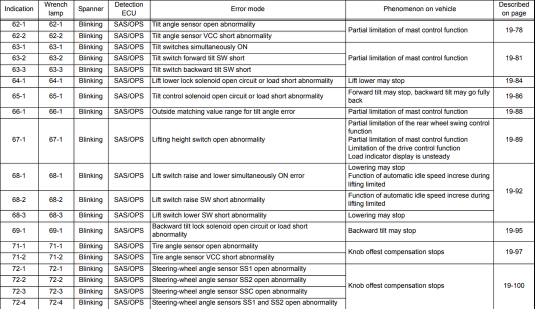
62-1 Tilt angle sensor abnormal Mast control function is partially restricted Connector is faulty
62-2 Connector cable is damaged
Broken tilt angle sensor
Controller is broken
63-1 Tilt lever switch abnormal Mast control function is partially restricted Connector is faulty
63-2 Forward tilt switch is broken
63-3 Backward tilt switch is broken
Faulty switch installation
Controller is broken
64-1 Lift lock solenoid abnormal Fork won’t come down Connector is broken
Broken connector cable
Broken lift lock solenoid
Controller is broken
65-1 Tilt control solenoid abnormal Forward tilt cannot operate, but Connector is damaged
backward tilt operable. Broken connector cable
Broken tilt control solenoid
Controller is broken
66-1 Abnormal matching measurement value The control mast function is partially restricted. The horizontal tilt angle value does not match.
Tilt forward angle value
it is not in accordance with.
Measuring value of load sensor
it is not in accordance with.
67-1 Lifting height switch abnormal Partial rearwheel swing control function Faulty connector
restricted. Broken connector cable
Mast control function is partially restricted Lifting height swt is broken
Drive control function is restricted Controller is faulty
Load indicator display changes IG fuse blown
Broken connector cable
The swt elevator installation is broken
Controller is broken
Error mode Symptoms on the forklift Possible cause of failure
69-1 Backward tilt lock solenoid Backward tilt does not operate Connector is faulty
abnormal Connector cable is damaged
Backward tilt lock solenoid is faulty.
Controller is broken
71-1 Tire angle sensor abnormal Steer knob is not in position Connector is faulty
71-2 Connector cable is damaged
tire angle sensor joint,
rear axle link syst. damaged
Controller is broken
72-1 Steering angle sensor abnormal Steer knob is not in position Connector is faulty
72-2 Connector cable is damaged
72-3 Sensor is faulty
72-4 Controller is faulty
73-1 Abnormal solenoid knob position Steer knob out of position Connector is faulty
Broken connector cable
Controller is broken
74-1 Measuring value of matching tire angle Steer knob is not in position Matching value
wheel alignment error no in accordance
A5-1 Seat switch abnormal Drive & hydraulic system can operate Connector is faulty
even if the operator is not sitting in the operating chair The connector cable is damaged
Controller is broken
A7-1 Abnormal brake switch Function of partially restricted drive control Connector is faulty
Broken brake switch
Broken connector cable
Controller is broken
AF-1
AF-2
AF-3
AF-4
AF-5
AF-6
AF-7
AF-8 CPU abnormal All control functions are unstable Controller is faulty
C7-1 Shift lever switch abnormal Cannot be positioned to neutral Connector is faulty
C7-2 Drive control function is partially restricted Forward switch is faulty
Reverse switch is broken
Faulty switch installation
Controller is broken
CA-1 Forward-reverse travel Torque Drive system and hydraulic system can Connector damaged
converter relay abnormal is operated even when operator is not seated Forward travel cable
the relay operator seat is broken
Forward travel relay
reverse travel cable
Reverse travel relay
Controller is broken
EC-1 Unload solenoid abnormal Drive system and hydraulic system can Connector is faulty
operated even if the operator is not seated Connector cable is damaged
in operator seat Unload solenoid is broken
Controller is broken
F1-1 Combination meter abnormal Problem on the display Connector is damaged
F1-2 Hour meter cable is damaged
Hour meter is broken
Controller is broken
F4-1~8 CPU error CPU abnormal Multi-function board
H1-1 Lift lever potentiometer abnormal Lift cannot operate Connectro is faulty
H1-2 The potentiometer wire is damaged
H1-3 Potentiometer is broken
H1-4 Controller is broken
H1-5 Fuse blown
H2-1 Tilt lever potentiometer abnormal Tilt does not operate Connectro is faulty
H2-2 The potentiometer wire is damaged
H2-3 Potentiometer is broken
H2-4 Controller is broken
H2-5 Fuse blown
H3-1 Attachment 1 lever potentiometer Attachment 1 does not operate Connectro is faulty
H3-2 abnormal Potentiometer cable is damaged
H3-3 The potentiometer is faulty
H3-4 Controller is broken
H3-5 Fuse blown
H4-1 Attachment 2 lever potentiometer Attachment 2 does not operate Connectro is damaged
H4-2 abnormal Potentiometer cable is damaged
H4-3 The potentiometer is faulty
H4-4 Controller is broken
H4-5 Fuse blown
H5-1 Lift solenoid abnormal Elevator may not operate Faulty connector
H5-2 Elevator cable (PUSH) is damaged
Solenoid lift (PUSH) is broken
Elevator cable (PULL) is broken
Solenoid lift (PULL) is broken
Controller is broken
H6-1 Solenoid Tilt Abnormal Tilt may not operate Connector is faulty
H6-2 Faulty tilt (PUSH) cable
Solenoid tilt (PUSH) faulty
Broken tilt (PULL) cable
Solenoid tilt (PULL) faulty
Controller is broken
H7-1 Attachment 1 abnormal solenoid Attachment 1 may not work Connector is damaged
H7-2 operating Att 1 (PUSH) cable is faulty
Solenoid Att 1 (PUSH) is faulty
Att 1 (PULL) cable is damaged
Solenoid Att 1 (PULL) is faulty
Controller is broken
Solenoid Att 2 (PUSH) is faulty
Att 2 (PULL) cable is damaged
Solenoid Att 2 (PULL) is faulty
Controller is broken
HA-1 3/4-way change relay abnormal Attachment transfer is not possible Connector is damaged
operating Relay cable 1 is damaged
Relay 1 is broken
Relay cable 2 is damaged
Relay 2 is broken
Controller is broken
Error mode Symptoms on forklift Possible causes
broken WARNING LIST
IF THE WRENCH LAMP IS ON AND WITH THESE SYMPTOMS BELOW ON
владимир (Monday, 21 March 2022 05:06)
ERROR 107 вилочный погрузчик HANGCNA
Kasco (Wednesday, 09 March 2022 12:10)
Error code C5-5 not moving
si (Monday, 02 August 2021 18:42)
Omar orduno (Sunday, 13 June 2021 22:45)
montacargas eléctrico Toyota modelo 7fcu15 presenta error c3-1
nam (Friday, 11 June 2021 11:18)
toyota 7fbrs 15 error code f5-1 , f5-4
Ravindu Bandara (Tuesday, 08 June 2021 08:15)
What is the meaning of E 59-1 error code in GENEO 35
zoltan (Tuesday, 16 March 2021 09:41)
1C-2 code 52-8FDF25 (1ZS engine)
Anybody knows this code?
de Vries (Wednesday, 24 February 2021 19:51)
Mijn toyota traico heeft foutcode 73 wat houdt dat in?
Joel (Friday, 13 November 2020 23:05)
Just serviced 7 series 7fbcu30 and need to reset the maintenance timer
Joel (Friday, 13 November 2020 23:02)
How to reset maintenance hours reminder
Armando garrido (Wednesday, 23 September 2020 21:14)
Ole (Monday, 21 September 2020 08:30)
does anyone know the error code «joy M not connected»
Robert Sieow (Tuesday, 28 July 2020 16:22)
Gustavo D (Tuesday, 14 April 2020 16:01)
I have a Toyota diesel forklift model 8FDU20 a code came up on the display (E AD 1) the machine won’t start. I checked many different connectors and sensors but nothing seemed wrong.
I need some fresh ideas from someone smart, please help!
Jose (Thursday, 30 January 2020 21:49)
Tengo un equipo Toyota 8fdu30 serie 60532 me da código 11-5 y deja de caminar hacia el frente
manish chauhan (Wednesday, 29 January 2020 17:27)
it is most usebal document
JIM K (Monday, 27 January 2020 13:07)
Working on a Hyster ROES30 order picker which has a code A5 31 on display board in the lower part of the compartment, NEED HELP
Josh Gering (Tuesday, 21 January 2020 23:26)
Code 72-4 Steering angle sensor.
Lift does not have said sensor. How do I remove/disable this parameter? Everything working fine, but lift won’t quit alarming. Customer getting irritated.
kwan (Tuesday, 05 November 2019 15:59)
Rick (Wednesday, 07 August 2019 21:33)
I have a toyota Electric Fork lift That has had some serious problems as I had to get into it pretty deep to find out why when the owners guys turned on the key nothing powered up? Im not a class A electric fork lift technician but I know enough about electrical that I chased down a Five pin plug that was all melted together and shorted out I removed burnt socket and replaced the burnt wires and got power back to the ignition and truck I got it so it powers the hoist and power steering but have do final drive forward or reverse I have a wrench and a Code A 8 I did see another electrical socket that looked burnt pretty badly I didnt play with it but I’m thinking I’m probably going to have to cut that socket out and clean wires back and reconnect them together to get the drive motor to start so the fork truck can move back and forth! I’m trying to find out what the A 8 code is and the proper way to reset the computer to remove the wrench symbol and clear all codes. Thank you for your time, Rickey
Kevin Stahl (Wednesday, 29 May 2019 19:18)
Please could you email me the code sheet of a Toyota electric forklift Model number 5FBE15
Pepo (Wednesday, 15 May 2019 22:07)
I’ve been fighting with this code h5-1
Robert Shamonski (Monday, 22 April 2019 20:45)
EA5-1 trying to identify code
Jose Sanchez (Monday, 15 April 2019 17:58)
I have a forklift 3 wheel sit down model number 7FBEU15 and a code pops up that is AD6 and AD5 if you can help me what those code mean I’ll appreciate it
Sammy G. Polinar (Thursday, 04 April 2019 09:13)
Please provide me the Electrical Diagram of Toyota Electric Fork Lift Model: 7FBE20.
My Fork Lift is stop due to Electrical Problem
If you are the copyright holder of a user manual, please contact us by mail and we will remove it from the site and leave a link to your store if there is one.
При возникновении неисправности на технике, информационный дисплей EMS сразу отображает на экране ошибки, при этом зуммер (сигнализатор) начинает пищать. Для отключения зуммера нужно нажать на кнопку ACK на мониторе JCB.
Подробное описание ошибок электронных блоков управления гидравлики ECU1 728/29900 728/35700 728/29900 728/35700 и блока электроники ECUW 728/35800 728/18500 728/15500 JCB.
Коды ошибок JCB (гидравлики и электроники)

| Коды ошибок |
Надпись на дисплее монитора | Описание неисправности |
| 101 | CRANK | ЭБУ1 не обнаруживает сигнал от коленвала. |
| 102 | FUEL | Цепь датчика топлива разомкнута |
| 103 | EN TMP | Цепь датчика температуры двигателя разомкнута. |
| 104 | HYD TMP | Цепь датчика температуры гидравлической жидкости разомкнута. |
| 105 | SET PT | Цепь потенциометра заданного положения дроссельной заслонки разомкнута. |
| 106 | SENS PT | Цепь потенциометра фактического положения дроссельной заслонки разомкнута. |
| 107 | OIL SW | Датчик давления масла выдает сигнал наличия давления при отключенном двигателе. |
| 108 | FLYWHEEL | Датчик карданной передачи выдает сигнал оборотов двигателя при отключенном |
| 109 | ALT | Генератор выдает сигнал наличия напряжения при отключенном двигателе. |
| 110 | THR SOL | Цепь электромагнитного клапана дроссельной заслонки разомкнута. Обнаруживается только при отключенном двигателе. |
| 111 | BOOM SP | Цепь регулирования малой скорости стрелы разомкнута. |
| 113 | MAX FLW | Цепь электромагнитного клапана максимального расхода разомкнута. Для машин JS200W данная ошибка может быть обнаружена тольк |
| 115 | BOOM | Цепь электромагнитного клапана приоритета разомкнута |
| 116 | FL PMP | Цепь выходного контура насоса дозаправки разомкнута. |
| 117 | HORN | Цепь выходного контура клаксона разомкнута. |
| 118 | HYD PMP | Цепь гидравлического насоса разомкнута. Поскольку клапан является пропорциональным, ошибка обнаруживается только при отключенном двигателе |
| 119 | SLW LCK | Цепь электромагнитного клапана блокиратора стрелы разомкнута. |
| 120 | HYD FAN | Цепь выходного контура вентилятора гидросистемы разомкнута. Обнаруживается только при отключенном двигателе |
| 121 | SLW BRK | Цепь электромагнитного клапана разблокировки стрелы разомкнута |
| 122 | SLW ST | Цепь электромагнитного клапана отключения стрелы разомкнута. |
| 127 | TL CHNG | Цепь электромагнитного клапана переключения скорости движения разомкнута. |
| 128 | WASHER | Цепь двигателя омывателя разомкнута. |
| 129 | DOZER | Цепь электромагнитного клапана отвала разомкнута. |
| 130 | GRB CW | Цепь электромагнитного клапана вращения грейфера по часовой стрелке разомкнута. |
| 131 | GRB CCW | Цепь электромагнитного клапана вращения грейфера против часовой стрелки разомкнута. |
| 132 | LW FLOW | Цепь электромагнитного клапана низкого расхода разомкнута. |
| 133 | ISOL | Цепь электромагнитного клапана гидроизолятора разомкнута. |
| 135 | 2 STAGE | Цепь предохранительного электромагнитного клапана ступени 2 разомкнута. |
| 136 | QK HTCH | Цепь электромагнитного клапана быстрой сцепки разомкнута. |
| 138 | HAMMER | Цепь электромагнитного клапана молота разомкнута. |
| 139 | CUSHION | Цепь электромагнитного клапана твердой/мягкой подушки разомкнута. |
| 142 | ENG SD | Цепь выходного контура отключения двигателя разомкнута. |
| 143 | GLW PLG | Цепь выходного контура свечей накаливания разомкнута. |
| 156 | TL FLW3 | Цепь электромагнитного клапана расхода 3 движения разомкнута. |
| 157 | TL FLW2 | Цепь электромагнитного клапана расхода 2 движения разомкнута. |
| 158 | GR CHNG | Цепь электромагнитного клапана М2 или переключения передач разомкнута. |
| 159 | BRKE LT | Цепь выходного контура лампы тормоза разомкнута. |
| 160 | AXLE LK | Цепь электромагнитного клапана блокировки моста разомкнута. |
| 161 | STAB UP | Цепь электромагнитного клапана подъема стабилизатора разомкнута. |
| 162 | STAB DIN | Цепь электромагнитного клапана опускания стабилизатора разомкнута. |
| 163 | STAB LH | Цепь электромагнитного клапана левого стабилизатора разомкнута. |
| 164 | STAB RH | Цепь электромагнитного клапана правого стабилизатора разомкнута. |
| 165 | CRUISE | Цепь электромагнитного клапана круиз-контроля разомкнута. |
| 166 | DIG ISL | Цепь электромагнитного клапана изолятора режущей кромки разомкнута. |
| 167 | PRK BK | Цепь электромагнитного клапана М1 или стояночного тормоза разомкнута. |
| 168 | DRV ISL | Цепь электромагнитного клапана изолятора привода разомкнута. |
| 202 | FUEL | Короткое замыкание цепи датчика уровня топлива. |
| 203 | EN TMP | Короткое замыкание цепи датчика температуры двигателя. |
| 204 | HYD TMP | Короткое замыкание цепи датчика температуры гидравлической жидкости. |
| 205 | SET PT | Короткое замыкание цепи потенциометра заданного положения дроссельной заслонки. |
| 206 | SENS PT | Короткое замыкание цепи потенциометра фактического положения дроссельной заслонки. |
| 210 | THR SOL | Короткое замыкание цепи электромагнитного клапана дроссельной заслонки. Обнаруживается только при отключенном двигателе. |
| 211 | BOOM SP | Короткое замыкание цепи регулирования малой скорости стрелы. |
| 212 | INT LT | Короткое замыкание цепи внутреннего освещения. |
| 213 | MAX FLW | Короткое замыкание цепи электромагнитного клапана максимального расхода. Для машин JS200W данная ошибка может быть обнаружена только при отключенном двигателе, т. к. на этих машинах имеется пропорциональный клапан. |
| 214 | BEACON | Короткое замыкание цепи маячка. |
| 215 | BOOM PR | Короткое замыкание цепи электромагнитного клапана приоритета. |
| 216 | FL PMP | Короткое замыкание цепи электромагнитного клапана насоса дозаправки. |
| 217 | HORN | Короткое замыкание цепи клаксона. |
| 218 | HYD PMP | Короткое замыкание цепи гидравлического насоса. Поскольку клапан является пропорциональным, ошибка обнаруживается только при отключенном двигателе. |
| 218 | HYD PMP | Короткое замыкание цепи гидравлического насоса. Поскольку клапан является пропорциональным, ошибка обнаруживается только при отключенном двигателе. |
| 219 | SLW LCK | Короткое замыкание цепи электромагнитного клапана блокиратора стрелы. 220 HYD FAN Короткое замыкание цепи электромагнитного клапана вентилятора гидросистемы |
| 220 | HYD FAN | Короткое замыкание цепи электромагнитного клапана вентилятора гидросистемы. Обнаруживается только при отключенном двигателе. |
| 221 | SLW BRK | Короткое замыкание цепи электромагнитного клапана разблокировки стрелы. |
| 222 | SLW ST | Короткое замыкание цепи электромагнитного клапана отключения стрелы. |
| 223 | LW WIPR | Короткое замыкание цепи нижнего стеклоочистителя. |
| 224 | WIPER | Короткое замыкание цепи стеклоочистителя. |
| 225 | LH CAB LT | Короткое замыкание цепи рабочего освещения стрелы. |
| 226 | RH CAB LT | Короткое замыкание цепи рабочего освещения инструментального ящика. |
| 227 | TL CHNG | Короткое замыкание цепи электромагнитного клапана переключения скорости движения. |
| 228 | WASHER | Короткое замыкание цепи двигателя омывателя. |
| 229 | DOZER | Короткое замыкание цепи электромагнитного клапана отвала. |
| 230 | GRB CW | Короткое замыкание цепи электромагнитного клапана вращения грейфера по часовой стрелке. |
| 231 | GRB CCW | Короткое замыкание цепи электромагнитного клапана вращения грейфера против часовой стрелки. |
| 232 | LW FLOW | Короткое замыкание цепи электромагнитного клапана низкого расхода. |
| 233 | ISOL | Короткое замыкание цепи электромагнитного клапана изолятора. |
| 234 | EMG STP | Короткое замыкание цепи электромагнитного клапана аварийной остановки. |
| 235 | 2 STAGE | Короткое замыкание цепи предохранительного электромагнитного клапана ступени 2. |
| 236 | QK HTCH | Короткое замыкание цепи электромагнитного клапана быстрой сцепки. |
| 237 | TL ALRM | Короткое замыкание цепи сигнализации трогания с места. |
| 238 | HAMMER | Короткое замыкание цепи электромагнитного клапана молота. |
| 239 | CUSHION | Короткое замыкание цепи электромагнитного клапана твердой/мягкой подушки. |
| 240 | BOOM LT | Короткое замыкание цепи рабочего освещения стрелы. |
| 241 | ENG SD | Короткое замыкание цепи электромагнитного клапана остановки двигателя. |
| 242 | ENG SD | Короткое замыкание цепи электромагнитного клапана остановки двигателя. |
| 243 | GLW PLG | Короткое замыкание цепи свечей накаливания. |
| 244 | CNT LT | Короткое замыкание цепи рабочего освещения противовеса. |
| 244 | LH IND | Короткое замыкание цепи индикатора левого поворота. |
| 245 | LH IND | Короткое замыкание цепи индикатора левого поворота. |
| 246 | LH SIDE | Короткое замыкание цепи левого бокового освещения. |
| 247 | LH FOG | Короткое замыкание цепи левой противотуманной фары. |
| 248 | LH MAIN | Короткое замыкание цепи левой фары дальнего света. |
| 249 | LH DIP | Короткое замыкание цепи левой фары ближнего света. |
| 250 | RH IND | Короткое замыкание цепи индикатора правого поворота. |
| 251 | RH SIDE | Короткое замыкание цепи правого бокового освещения. |
| 252 | RH FOG | Короткое замыкание цепи правой противотуманной фары. |
| 253 | RRH MAIN | Короткое замыкание цепи правой фары дальнего света. |
| 254 | RH DIP | Короткое замыкание цепи правой фары ближнего света. |
| 255 | HZD LED | Короткое замыкание цепи светодиода опасности. |
| 256 | TL FLW3 | Короткое замыкание цепи электромагнитного клапана расхода 3 движения. |
| 257 | TL FLW2 | Короткое замыкание цепи электромагнитного клапана расхода 2 движения. |
| 258 | GR CHNG | Короткое замыкание цепи электромагнитного клапана М2 или переключения передач. |
| 259 | BRKE LT | Короткое замыкание цепи выходного контура лампы тормоза. |
| 260 | AXLE LK | Короткое замыкание цепи электромагнитного клапана блокировки моста. |
| 261 | STAB UP | Короткое замыкание цепи электромагнитного клапана подъема стабилизатора. |
| 262 | STAB DIN | Короткое замыкание цепи электромагнитного клапана опускания стабилизатора. |
| 263 | STAB LH | Короткое замыкание цепи электромагнитного клапана левого стабилизатора. |
| 264 | STAB RH | Короткое замыкание цепи электромагнитного клапана правого стабилизатора. |
| 265 | CRUISE | Короткое замыкание цепи электромагнитного клапана круиз-контроля. |
| 266 | DIG ISL | Короткое замыкание цепи электромагнитного клапана изолятора режущей кромки. |
| 267 | PRK BK | Короткое замыкание цепи электромагнитного клапана М1 или стояночного тормоза. |
| 268 | DRV ISL | Короткое замыкание цепи электромагнитного клапана изолятора привода. |
| 300 | EC1 CAN | Прервана связь ЭБУ1 с шиной CAN. |
| 301 | ECW CAN | Прервана связь ECUW с шиной CAN. |
| 302 | THRT CAL | Разница между точкам максимальной и минимальной калибровки для циферблатного потенциометра дроссельной заслонки меньше 100 точек A/D. |
| 304 | THRT CAL | Положение циферблатного потенциометра изменено более, чем на 10%, но двигатель продолжает работать в положении холостого хода. Данное состояние должно длиться не менее 15 секунд, чтобы быть зафиксированным. Данная ошибка не существует на машинах с EEC (Electronic Engine Controller — блок электронного управления двигателем).. |
Коды ошибок Двигателя JCB (Isuzu 4HK, 6HK)
Вопрос-Ответ
Добрый день.
Вилочный погрузчик Тойота 02-8FG25, при включении зажигания горит ошибка Е67-1 и гаечный ключ.
Расшифровку не подскажете?
Где можно узнать коды ошибок на электропогрузчик HYUNDAI 25B-9. Особенно ошибка M4F — incorrect start. Все лючки закрыты, ручник — в нужном положении, ручка движения — в нейтрали.
Не могу дозвониться
Здраствуйте на вилочном погрузчике nissan загорелись ошибки f-16 и e-30, как рассшифровываются?
Подскажите, погрузчик nissan 3тонник выскакивает ошибка f-34, что за она и как с ней бороться?
Погрузчик mitsubishi FD15N Перииодически выскакивает ошибка F40 + красный восклицательный знак. В книжке нашел что это ошибка «рулевого управления». Так как ошибка не постоянна возможно дело в контакте. Подскажите какой датчик, провод или реле искать. Ошибка стала появляться после ремонта заднего моста и капиталки двигателя.
Электропогрузчик Hyster 1,6 выдает ошибку 21569. Что она означает.
К сожалению по Хайстер не смогу Вам подсказать. Если у Вас не будет других вариантов — напишите мне на почту, я покапаюсь в каталогах.
Добрый день!
Как проверить кол-во наработанных моточасов на погрузчике Maximal M16?
Спасибо!
На вилочном погрузчике YOYОTA «горит» ошибка: Е 67-14; Е 54-1; Е 71-1 и Е 85-1.
подскажите, пожалуйста, что это значит.
На дизельном вилочном погрузчике Ниссан мигает ошибка F-34 и мигает вся панель,плохо заводиться(такое ощущение что оходит топливо с насоса) и коптит при нажатии на педаль газа
Добрый день! Подскажите пожалуйста, на вилочном погрузчике NISSAN FL01A15 горят ошибки:
P-22 и F-80, что это за ошибки?
Спасибо!
Р22 это сбой рычага управления — его нужно выставить в нейтральное положение.
здравствуйте, у нас погрузчик ниссан L01 двигатель К15 , выдает ошибки Е34, Е39, F40 что это за ошибки. Заранее спасибо
Здравствуйте, у нас электропогрузчик sumitomo, после зарядки высвечивается ошибка 201, и сбрасывается, недозаряжает одно деление, через несколько секунд сбрасывается, в чем может быть причина?
Здравствуйте, у нас электрический транспалет HELI DC15. лампа ошибок мигает код отказа 13 (1 пауза 3). Что означает этот код? Спасибо заранее ха помощь
нет движения у вилочного погрузчика GPOWER FB 15-35.Появилась ошибка al-8/менял акселератор с рабочего погрузчика -тот же результат.Что может быть
Здравствуйте. Для диагностики электропогрузчиков нужно либо современное оборудование или подробные руководства. Для Вашего погрузчика, к сожалению, у меня ни того, ни того нет. Советую обратиться в сервисный центр Тойота Цусе.
Здравствуйте! Подскажите пожалуйста, где ( в каком месте ), установлен датчик температуры охлаждающей жидкости вилочного погрузчика MITSUBICHI
на вилочном Ниссане PL01 15 установлено заводское японское оборудование газ-бензин. На бензине все прекрасно а на газе троит двигатель моргает вся панель и ошибка Е-27, что это может быть и что делать?
Ошибка Е-27 это ошибка сенсора. Думаю, что у Вас вышел из строя переключатель газ/бензин. Вызовите специалиста по газовому оборудованию.
Добрый день! Приобрели вилочный погрузчик мицубиси fd25nt, дизельный двигатель (б/у). После того как погрузчик прогревается выдает ошибку F87 и перестает ехать назад. Подскажи пожалуйста в чем может быть причина и на что указывают данная ошибка. Заранее благодарны.
Данная ошибка — это ошибка электромагнитного клапана.на задний ход. Думаю, что требуется замена соленоида. Ремонтировать его бесполезно.
Здравствуйте, подскажите как проверить уровень масла в акпп погрузчика коматсу
FO18Y630 двигатель 4D92E-1B59B?
Посмотреть на щуп))) Рядом с фильтром АКПП Вы должны увидеть щуп АКПП. Выньте его и посмотрите — должны быть метки.
Спецпредложения
Грузоподъемность 1,8 тонны
Высота подъема 4,34 метра
Год выпуска 2013,
Мачта трехсекционная со свободным ходом (вагонник)
Находится в г. Саратов
ЦЕНА: 1 170 000 рублей

Грузоподъемность 1,5 тонны
Высота подъема 3,0 метров
Год выпуска 2013
Мачта двухсекционная
Свободный ход мачты (вагонный вариант)
Каретка бокового смещения вил
Шины суперэластик новые
Вилы 1070
Наработка 4631 м/ч
ПСМ в наличии
ЦЕНА: 1 150 000 рублей

Грузоподъемность 3 тонны
Высота подъема 3,0 метра
Год выпуска 2008
Мачта двухсекционная без свободного хода
Вилы 1070
Шины пневматические новые
Состояние нового погрузчика.
7FBCU15, 7FBCU18, 7FBCU20, 7FBCU25, 7FBCU30, 7FBCU32 7FBCU35, 7FBCU45, 7FBCU55, 7FBCHU18, 7FBCHU25 7FBEU15, 7FBEU18, 7FBEU20, 7FBEHU18, 7FGU15, 7FGU18 7FGU20, 7FGU25, 7FGU30, 7FGU32, 7FDU15, 7FDU18, 7FDU20 7FDU25, 7FDU30, 7FDU32, 8FGU15, 8FGU18, 8FGU20, 8FGU25 8FGU30, 8FGU32, 8FDU15, 8FDU18, 8FDU20, 8FDU25, 8FDU30 8FDU32, 7FGCU15, 7FGCU18, 7FGCU20, 7FGCSU20, 7FGCU25 7FGCU30, 7FGCU32, 8FGCU18, 8FGCU20, 8FGCSU20, 8FGCU25 8FGCU30, 8FGCU32, 7FGU35, 7FDU35, 7FGKU40, 7FDKU40 7FGU45, 7FDU45, 7FGAU50, 7FDAU50, 7FGU60, 7FDU60, 7FGU70 7FDU70, 7FGU80, 7FDU80, 7FGCU35, 7FGCU45, 7FGCU55 7FGCU60, 7FGCU70
GENERAL INFORMATION:
Further information concerning these codes can be found in the following manuals:
7FBCU15-55 ►OPSS Manual CU335 page 3-9 7FBEU15-20 ►OPSS Manual CU341 page 1-10 7FGCU15, 18, S20 ►OPSS Manual CU042 page 1-19 7FGU15-32, 7FDU15-32, 7FGCU20-32 ►OPSS Manual CU040 page 1-18 7FGU35-80, 7FDU35-80, 7FGCU35-70 ►OPSS Manual CU041 page 1-17 8FGCU15, 18, S20 ►Service manual 00700-X8880-71 page 19.1-82 8FGU15-32, 8FDU15-32, 8FGCU20-32 ►Service manual 00700-X8880-71 page 19-111
DIAGNOSIS DISPLAY METHOD
1. Diagnosis display method The diagnosis is displayed by means of an error code as shown in the illustration to the left, and by the lights turning on. When the ignition key switch is turned ON, the lamp lights once to allow checking for the bulb, and then turns off again if the status is normal. With the ignition key switch ON, if an abnormality is detected when the vehicle is stopped, travelling or performing meterials handling operations, an error code is displayed and the lamps turn on as a warning. When this happens, stop the vehicle immediately and check the error code.
(3) Connect the matching connector and turn the ignition key switch OFF.
LIST OF DIAGNOSIS CODES
Translated from Indonesian!
Original text error codes Download
41-1 Matching connector abnormal Only the Connector display is faulty
Matching cable is broken
Controller is broken
51-1 Speed sensor abnormal Speed indicator keeps showing 0 km/h Connector is faulty
51-2 Rear wheel swing control Damaged connector cable
Steer knob is not in position Speed sensor is broken
Controller is broken
52-1 Yaw rate sensor abnormal Rear wheel swing control is limited. Broken connector
52-2 Connector cable is damaged
52-3 Yaw rate sensor is faulty
Controller is broken
54-1 Swing lock solenoid abnormal Rear wheel swing control is limited. Broken connector
Broken connector cable
Swing lock solenoid is broken
Controller is broken
61-1 Load sensor abnormal Rear wheel swing control is limited. Broken connector
61-2 Control mast function is partially restricted Connector cable is damaged
Drive control function is limited (MFD opt) Load sensor is faulty
Load indicator does not appear on the display (MFD) The controller is broken
Error mode Symptoms on forklift Possible causes
62-1 Tilt angle sensor abnormal Mast control function is partially restricted Connector is faulty
62-2 Connector cable is damaged
Broken tilt angle sensor
Controller is broken
63-1 Tilt lever switch abnormal Mast control function is partially restricted Connector is faulty
63-2 Forward tilt switch is broken
63-3 Backward tilt switch is broken
Faulty switch installation
Controller is broken
64-1 Lift lock solenoid abnormal Fork won’t come down Connector is broken
Broken connector cable
Broken lift lock solenoid
Controller is broken
65-1 Tilt control solenoid abnormal Forward tilt cannot operate, but Connector is damaged
backward tilt operable. Broken connector cable
Broken tilt control solenoid
Controller is broken
66-1 Abnormal matching measurement value The control mast function is partially restricted. The horizontal tilt angle value does not match.
Tilt forward angle value
it is not in accordance with.
Measuring value of load sensor
it is not in accordance with.
67-1 Lifting height switch abnormal Partial rearwheel swing control function Faulty connector
restricted. Broken connector cable
Mast control function is partially restricted Lifting height swt is broken
Drive control function is restricted Controller is faulty
Load indicator display changes IG fuse blown
Broken connector cable
The swt elevator installation is broken
Controller is broken
Error mode Symptoms on the forklift Possible cause of failure
69-1 Backward tilt lock solenoid Backward tilt does not operate Connector is faulty
abnormal Connector cable is damaged
Backward tilt lock solenoid is faulty.
Controller is broken
71-1 Tire angle sensor abnormal Steer knob is not in position Connector is faulty
71-2 Connector cable is damaged
tire angle sensor joint,
rear axle link syst. damaged
Controller is broken
72-1 Steering angle sensor abnormal Steer knob is not in position Connector is faulty
72-2 Connector cable is damaged
72-3 Sensor is faulty
72-4 Controller is faulty
73-1 Abnormal solenoid knob position Steer knob out of position Connector is faulty
Broken connector cable
Controller is broken
74-1 Measuring value of matching tire angle Steer knob is not in position Matching value
wheel alignment error no in accordance
A5-1 Seat switch abnormal Drive & hydraulic system can operate Connector is faulty
even if the operator is not sitting in the operating chair The connector cable is damaged
Controller is broken
A7-1 Abnormal brake switch Function of partially restricted drive control Connector is faulty
Broken brake switch
Broken connector cable
Controller is broken
AF-1
AF-2
AF-3
AF-4
AF-5
AF-6
AF-7
AF-8 CPU abnormal All control functions are unstable Controller is faulty
C7-1 Shift lever switch abnormal Cannot be positioned to neutral Connector is faulty
C7-2 Drive control function is partially restricted Forward switch is faulty
Reverse switch is broken
Faulty switch installation
Controller is broken
CA-1 Forward-reverse travel Torque Drive system and hydraulic system can Connector damaged
converter relay abnormal is operated even when operator is not seated Forward travel cable
the relay operator seat is broken
Forward travel relay
reverse travel cable
Reverse travel relay
Controller is broken
EC-1 Unload solenoid abnormal Drive system and hydraulic system can Connector is faulty
operated even if the operator is not seated Connector cable is damaged
in operator seat Unload solenoid is broken
Controller is broken
F1-1 Combination meter abnormal Problem on the display Connector is damaged
F1-2 Hour meter cable is damaged
Hour meter is broken
Controller is broken
F4-1~8 CPU error CPU abnormal Multi-function board
H1-1 Lift lever potentiometer abnormal Lift cannot operate Connectro is faulty
H1-2 The potentiometer wire is damaged
H1-3 Potentiometer is broken
H1-4 Controller is broken
H1-5 Fuse blown
H2-1 Tilt lever potentiometer abnormal Tilt does not operate Connectro is faulty
H2-2 The potentiometer wire is damaged
H2-3 Potentiometer is broken
H2-4 Controller is broken
H2-5 Fuse blown
H3-1 Attachment 1 lever potentiometer Attachment 1 does not operate Connectro is faulty
H3-2 abnormal Potentiometer cable is damaged
H3-3 The potentiometer is faulty
H3-4 Controller is broken
H3-5 Fuse blown
H4-1 Attachment 2 lever potentiometer Attachment 2 does not operate Connectro is damaged
H4-2 abnormal Potentiometer cable is damaged
H4-3 The potentiometer is faulty
H4-4 Controller is broken
H4-5 Fuse blown
H5-1 Lift solenoid abnormal Elevator may not operate Faulty connector
H5-2 Elevator cable (PUSH) is damaged
Solenoid lift (PUSH) is broken
Elevator cable (PULL) is broken
Solenoid lift (PULL) is broken
Controller is broken
H6-1 Solenoid Tilt Abnormal Tilt may not operate Connector is faulty
H6-2 Faulty tilt (PUSH) cable
Solenoid tilt (PUSH) faulty
Broken tilt (PULL) cable
Solenoid tilt (PULL) faulty
Controller is broken
H7-1 Attachment 1 abnormal solenoid Attachment 1 may not work Connector is damaged
H7-2 operating Att 1 (PUSH) cable is faulty
Solenoid Att 1 (PUSH) is faulty
Att 1 (PULL) cable is damaged
Solenoid Att 1 (PULL) is faulty
Controller is broken
Solenoid Att 2 (PUSH) is faulty
Att 2 (PULL) cable is damaged
Solenoid Att 2 (PULL) is faulty
Controller is broken
HA-1 3/4-way change relay abnormal Attachment transfer is not possible Connector is damaged
operating Relay cable 1 is damaged
Relay 1 is broken
Relay cable 2 is damaged
Relay 2 is broken
Controller is broken
Error mode Symptoms on forklift Possible causes
broken WARNING LIST
IF THE WRENCH LAMP IS ON AND WITH THESE SYMPTOMS BELOW ON
владимир (Monday, 21 March 2022 05:06)
ERROR 107 вилочный погрузчик HANGCNA
Kasco (Wednesday, 09 March 2022 12:10)
Error code C5-5 not moving
si (Monday, 02 August 2021 18:42)
Omar orduno (Sunday, 13 June 2021 22:45)
montacargas eléctrico Toyota modelo 7fcu15 presenta error c3-1
nam (Friday, 11 June 2021 11:18)
toyota 7fbrs 15 error code f5-1 , f5-4
Ravindu Bandara (Tuesday, 08 June 2021 08:15)
What is the meaning of E 59-1 error code in GENEO 35
zoltan (Tuesday, 16 March 2021 09:41)
1C-2 code 52-8FDF25 (1ZS engine)
Anybody knows this code?
de Vries (Wednesday, 24 February 2021 19:51)
Mijn toyota traico heeft foutcode 73 wat houdt dat in?
Joel (Friday, 13 November 2020 23:05)
Just serviced 7 series 7fbcu30 and need to reset the maintenance timer
Joel (Friday, 13 November 2020 23:02)
How to reset maintenance hours reminder
Armando garrido (Wednesday, 23 September 2020 21:14)
Ole (Monday, 21 September 2020 08:30)
does anyone know the error code «joy M not connected»
Robert Sieow (Tuesday, 28 July 2020 16:22)
Gustavo D (Tuesday, 14 April 2020 16:01)
I have a Toyota diesel forklift model 8FDU20 a code came up on the display (E AD 1) the machine won’t start. I checked many different connectors and sensors but nothing seemed wrong.
I need some fresh ideas from someone smart, please help!
Jose (Thursday, 30 January 2020 21:49)
Tengo un equipo Toyota 8fdu30 serie 60532 me da código 11-5 y deja de caminar hacia el frente
manish chauhan (Wednesday, 29 January 2020 17:27)
it is most usebal document
JIM K (Monday, 27 January 2020 13:07)
Working on a Hyster ROES30 order picker which has a code A5 31 on display board in the lower part of the compartment, NEED HELP
Josh Gering (Tuesday, 21 January 2020 23:26)
Code 72-4 Steering angle sensor.
Lift does not have said sensor. How do I remove/disable this parameter? Everything working fine, but lift won’t quit alarming. Customer getting irritated.
kwan (Tuesday, 05 November 2019 15:59)
Rick (Wednesday, 07 August 2019 21:33)
I have a toyota Electric Fork lift That has had some serious problems as I had to get into it pretty deep to find out why when the owners guys turned on the key nothing powered up? Im not a class A electric fork lift technician but I know enough about electrical that I chased down a Five pin plug that was all melted together and shorted out I removed burnt socket and replaced the burnt wires and got power back to the ignition and truck I got it so it powers the hoist and power steering but have do final drive forward or reverse I have a wrench and a Code A 8 I did see another electrical socket that looked burnt pretty badly I didnt play with it but I’m thinking I’m probably going to have to cut that socket out and clean wires back and reconnect them together to get the drive motor to start so the fork truck can move back and forth! I’m trying to find out what the A 8 code is and the proper way to reset the computer to remove the wrench symbol and clear all codes. Thank you for your time, Rickey
Kevin Stahl (Wednesday, 29 May 2019 19:18)
Please could you email me the code sheet of a Toyota electric forklift Model number 5FBE15
Pepo (Wednesday, 15 May 2019 22:07)
I’ve been fighting with this code h5-1
Robert Shamonski (Monday, 22 April 2019 20:45)
EA5-1 trying to identify code
Jose Sanchez (Monday, 15 April 2019 17:58)
I have a forklift 3 wheel sit down model number 7FBEU15 and a code pops up that is AD6 and AD5 if you can help me what those code mean I’ll appreciate it
Sammy G. Polinar (Thursday, 04 April 2019 09:13)
Please provide me the Electrical Diagram of Toyota Electric Fork Lift Model: 7FBE20.
My Fork Lift is stop due to Electrical Problem
If you are the copyright holder of a user manual, please contact us by mail and we will remove it from the site and leave a link to your store if there is one.
Читайте также:
- Электрическая схема ваз 2104 инжектор с описанием
- Схема предохранителей тойота матрикс 2003
- C1142 ошибка форд фокус 2
- Схема вакуумных трубок мерседес 123
- Заднее правое сиденье не зафиксировано bmw x7 ошибка
Файлы
Раздел содержит файлы для скачивания по теме вилочных погрузчиков.
Инструкции по эксплуатации |
Инструкции по эксплуатации вилочных погрузчиковДоступны для скачивания инструкции и руководства для погрузчиков: Komatsu, Toyota, Yale. Все инструкции для вилочных погрузчиков содержат следующую информацию:
Руководство оператора штабелераДоступно для скачивания руководство оператора для штабелера BT. Кроме стандартной информации инструкция содержит цифровые коды предупреждений и ошибок. |
 Руководство оператора штабелера BT SPE125 SPE160 |
| Правила техники безопасности Описание штабелера Технические данные Основные узлы и детали Органы управления Цифровые коды ошибок Вождение Перемещение грузов Аккумуляторная батарея Техобслуживание батареи График проведения планового техобслуживания Таблица смазки различных узлов и деталей |
|
Дата: 2015-01-07 18:06:12 Размер: 2.3 Мб Скачано: 17948 |
| Вернуться |
| Список категорий |
Showing items 1 — 7 of 7 results.
Sort messages by:
Hi, first of all you have to check encoders B18 & b19 &, sensors b46, b57&b58. If everything is ok you may try changing parameter 1273 and mast transition valves calibration. I had same fault, swapping between 180, 181& 182. I did it and it was true for me.
Hi, is there anyone here that has solved the issue with 4:182??? Please tell me if you found some solution. I`ve tried ti change the wire that messures the hight and done a software update.
i have the same problem. it have been changed between 4:181, 4:182 and 4: 180… i checked all sensors and wire… now i am testing the valves coils.
Had the same problem. Checked everything as per workshop manual, i.e height encoder, cable, software version etc. Called out Toyota who proceeded to spend 1 month trying to identify fault. Observed them changing controllers, changing hydraulic valve settings, upgrading software….. After 1 month they fixed the problem and told me the problem was wear in the lift chains and solved by adjusting them!
You can check the basics like the metal sensor bar, bowden cable & height counter for psychical damage.
I would disconnect the battery then check the electrical connectors at the height counter assembly.
If you had a BT CAN service key you could have looked at the diagnostic screen & see what the height counter channels & sensors are doing as you operate the truck.
FWIW: Since the RRE first came out back in 2009, ive only ever changed 1 height counter for an electrical fault — there normally bulletproof.
Thank you for the information. I have no BT CAN. Will I be able to do without him?
4:182 = No pulses from the free lift height sensor on lift/lowering.
Either defective free lift height counter assembly, the bowden cable is loose or there is a wiring fault.
Also check the metal sensor bar at the bottom of the mast as these can get bent & upset the sensor that activates the height counter.
Do you have a BT CAN service key?
Forkliftaction.com accepts no responsibility for forum content and requires forum participants to adhere to the rules. Click here for more information.
- Manuals
- Brands
- BT Manuals
- Trucks
- REFLEX RR B
- Service manual
-
Contents
-
Table of Contents
-
Bookmarks
Quick Links
Service Manual
en
REFLEX RR B,E RR B,E CC
Valid from serial number: 713962-
Order number: 218920-040
Issued: 2005-09-09 ITS
© BT Europe AB
https://www.forkliftpdfmanuals.com/
Related Manuals for BT REFLEX RR B
Summary of Contents for BT REFLEX RR B
-
Page 1
Service Manual REFLEX RR B,E RR B,E CC Valid from serial number: 713962- Order number: 218920-040 Issued: 2005-09-09 ITS © BT Europe AB https://www.forkliftpdfmanuals.com/… -
Page 2
RR E7-8CC 713962- RR B2-3CC 713962- RR B4-5CC 713962- RR B7-8CC 713968- Some chapters in this manual covers only certain of the T-codes above. © BT Europe AB Service Manual REFLEX RR B,E RR B,E CC Approved by: K-G Andersson https://www.forkliftpdfmanuals.com/… -
Page 3: Table Of Contents
Safety regulations during maintenance work Cleaning and washing ……..4.2.1 Cleaning the exterior ………. 3 4.2.2 Cleaning the motor compartment ……. 3 4.2.3 Electrical components ……..3 Safe lifting…………. 1- 1 © BT Europe AB Service Manual REFLEX RR B/E, RR B/E CC https://www.forkliftpdfmanuals.com/…
-
Page 4
8.2.6 Fuses …………..2 8.2.7 Air filter …………..2 8.2.8 Emergency exit (12) ……….3 8.2.9 Lighting …………… 3 Driver protection – 0840 General …………1- 2 Service Manual REFLEX RR B/E, RR B/E CC © BT Europe AB https://www.forkliftpdfmanuals.com/… -
Page 5
Removing the gear wheel ……..2 Removing the brakes ……… 2 12.3.2 Assembling the drive motor …….. 3 Assembling the brakes ……..3 Assembling the gear wheel …….. 3 1- 3 © BT Europe AB Service Manual REFLEX RR B/E, RR B/E CC https://www.forkliftpdfmanuals.com/… -
Page 6
13.5.3 Leakage from the lower cover ……11 13.5.4 Replacing wheel bolts ……..12 Travel brake system – 3100.1 14-1 Without support arm brakes …….. 1 General …………1- 4 Service Manual REFLEX RR B/E, RR B/E CC © BT Europe AB https://www.forkliftpdfmanuals.com/… -
Page 7
15.4.3 Check the braking force ……..16 Multiple disc brake, support arm ….15.5.1 Assembling …………17 15.5.2 Dismantling …………18 15.5.3 Inspection …………19 15.5.4 Assembling …………19 1- 5 © BT Europe AB Service Manual REFLEX RR B/E, RR B/E CC https://www.forkliftpdfmanuals.com/… -
Page 8
Fork/support arm wheel – 3550.2 18-1 General …………Dismantling the wheel……..Assembling the drive wheel ……Dismantling the wheel bearing…… Assembling the wheel bearing …… 1- 6 Service Manual REFLEX RR B/E, RR B/E CC © BT Europe AB https://www.forkliftpdfmanuals.com/… -
Page 9
21.3.1 Figure 1 …………27 21.3.2 Figure 2 …………27 21.3.3 Figure 3 …………28 21.3.4 Figure 4 …………28 21.3.5 Figure 5 …………29 1- 7 © BT Europe AB Service Manual REFLEX RR B/E, RR B/E CC https://www.forkliftpdfmanuals.com/… -
Page 10
21.4.19 Weighing …………45 21.4.20 Driver identification ……… 46 Without pin code ……….46 With pin code ………… 46 Battery – 5110 22-1 Battery dimensions ……..1- 8 Service Manual REFLEX RR B/E, RR B/E CC © BT Europe AB https://www.forkliftpdfmanuals.com/… -
Page 11
Driver parameters 1-7 ……… 9 Parameter settingof all parameters….Clock …………..10 Parameters …………11 24.5.1 Parameter 1 …………. 15 24.5.2 Parameter 2 …………. 15 1- 9 © BT Europe AB Service Manual REFLEX RR B/E, RR B/E CC https://www.forkliftpdfmanuals.com/… -
Page 12
24.8.2 Safety logic …………26 Warning Codes without registration ….26 Warning codes with registration….Error Codes ……….24.10.1 Error codes with registration ……67 Keypad 25-99 1- 10 Service Manual REFLEX RR B/E, RR B/E CC © BT Europe AB https://www.forkliftpdfmanuals.com/… -
Page 13
Adjusting the maximum lifting capacity ..Hydraulic pump – 6140 27-1 General…………Replacing the hydraulic pump …… 27.2.1 Dismantling …………1 27.2.2 Assembling …………2 1- 11 © BT Europe AB Service Manual REFLEX RR B/E, RR B/E CC https://www.forkliftpdfmanuals.com/… -
Page 14
……… 4 Assembling the cylinder …….. 30.5.1 Assembling the cylinder in the mast ….4 Free lift cylinder – 6620 31-1 General …………Tools …………. 1- 12 Service Manual REFLEX RR B/E, RR B/E CC © BT Europe AB https://www.forkliftpdfmanuals.com/… -
Page 15
33.2.5 Assembling the ram ……….. 3 33.2.6 Assembling the rod seal ……..4 33.2.7 Assembling the cylinder ……..4 33.2.8 Assembling the fork carriage ……4 1- 13 © BT Europe AB Service Manual REFLEX RR B/E, RR B/E CC https://www.forkliftpdfmanuals.com/… -
Page 16
Dismantling the mast ……..Adjusting the play ……… 35.6.1 Adjusting the mast play……..12 Lateral play …………12 35.6.2 Radial play …………13 Assembly …………. 1- 14 Service Manual REFLEX RR B/E, RR B/E CC © BT Europe AB https://www.forkliftpdfmanuals.com/… -
Page 17
Fork …………..3 Extended fork …………. 3 Checking the fork carriage’s wearing strips .. Fork spread unit……….37.3.1 Servicing of fork spread unit ……. 6 1- 15 © BT Europe AB Service Manual REFLEX RR B/E, RR B/E CC https://www.forkliftpdfmanuals.com/… -
Page 18
38.3.10 Acid circulation ……….11 General …………. 11 BTM with acid circulation ……..11 Pump type APE, VPM ……..12 Pump type API ……….12 1- 16 Service Manual REFLEX RR B/E, RR B/E CC © BT Europe AB https://www.forkliftpdfmanuals.com/… -
Page 19
39.3.4 Tool buttons and menu list ……… 4 39.3.5 Information window ……….4 39.3.6 Status row …………4 Function for connection ……. Function for disconnecting……1- 17 © BT Europe AB Service Manual REFLEX RR B/E, RR B/E CC https://www.forkliftpdfmanuals.com/… -
Page 20
39.12.3 In the event of any problems with communication with CAN …………17 39.12.4 Uninstallation ……….17 Extra warning lights/alarm – 9370 40-1 General …………1- 18 Service Manual REFLEX RR B/E, RR B/E CC © BT Europe AB https://www.forkliftpdfmanuals.com/… -
Page 21
41.11.6 Parameter 7 ……….. 15 41.11.7 Parameter 8 ……….. 15 41.11.8 Parameter 9 ……….. 15 Programming parameters……Error codes ……….TV equipment – 9390 42-19 General…………1- 19 © BT Europe AB Service Manual REFLEX RR B/E, RR B/E CC https://www.forkliftpdfmanuals.com/… -
Page 22
Sorting …………Frame/chassis (0300) ……..45.5.1 Dismantling …………3 Material handling ……….3 Operator’s seat, cushion (0620)….45.6.1 Dismantling …………4 Material handling ……….4 1- 20 Service Manual REFLEX RR B/E, RR B/E CC © BT Europe AB https://www.forkliftpdfmanuals.com/… -
Page 23
Material handling ……….17 Electric motors (1700)……..45.17.1 Dismantling ………… 18 Material handling ……….18 Electric fan motor (1740) ……45.18.1 Dismantling ………… 19 Material handling ……….19 1- 21 © BT Europe AB Service Manual REFLEX RR B/E, RR B/E CC https://www.forkliftpdfmanuals.com/… -
Page 24
Hydraulic system, fitted on the mast (6300) . 45.29.1 Dismantling …………. 33 Material handling ……….33 Hydraulcylindrar (6600) ……. 45.30.1 Dismantling …………. 35 Material handling ……….35 1- 22 Service Manual REFLEX RR B/E, RR B/E CC © BT Europe AB https://www.forkliftpdfmanuals.com/… -
Page 25
Material handling ……….39 Optional electric equipment (9400)….45.36.1 Dismantling ………… 40 Material handling ……….40 Optional electric equipment (9400)….45.37.1 Dismantling ………… 41 Material handling ……….42 1- 23 © BT Europe AB Service Manual REFLEX RR B/E, RR B/E CC https://www.forkliftpdfmanuals.com/… -
Page 26
Table of contents T-code Applies from machine no. 403-414, 669-671, 716-718 713962- Date Order no. 2005-06-01 218920-040 This page is intentionally left blank 1- 24 Service Manual REFLEX RR B/E, RR B/E CC © BT Europe AB https://www.forkliftpdfmanuals.com/… -
Page 27: General Product Information — M2
— In areas that contain dust or gases which can cause fires or ex- plosions — As a tow-truck for trailers — To tow other trucks — To transport/lift passengers — To drive on gravel or grass © BT Europe AB Service Manual REFLEX RR B/E, RR B/E CC 2- 1 https://www.forkliftpdfmanuals.com/…
-
Page 28: Truck Data
The lifting capacity, lift height and weight are indicated on the identifica- tion plate of the truck. For the RR B/E CC, please add 240 kg for the cold-store cabin. 2- 2 Service Manual REFLEX RR B/E, RR B/E CC © BT Europe AB https://www.forkliftpdfmanuals.com/…
-
Page 29: Truck Dimensions
2165-3898 2271-4504 4790 Free lift 1416-3257 3816- 1524-3257 1691-3923 4149 Lift hight 4400-9500 10000- 4400-9500 4800-11500 11000 Mast height, max 5040-10140 10140- 5240-10140 5381-12081 11640 © BT Europe AB Service Manual REFLEX RR B/E, RR B/E CC 2- 3 https://www.forkliftpdfmanuals.com/…
-
Page 30
For the RR B/E CC, please add 20 mm for the cold-store cabin. For the RR B/E CC, please add 51 mm for the cold-store cabin. 2- 4 Service Manual REFLEX RR B/E, RR B/E CC © BT Europe AB https://www.forkliftpdfmanuals.com/… -
Page 31: Identification Plate, Truck
LIFT HEIGHT ACTUAL CAPACITY LOAD CENTRE THE TRUCK MUST ALWAYS BE DRIVEN WITH LOW- ERED FORKS AND RETRACTED MAST EXCEPT WHEN PLACING OR REMOVING LOAD. © BT Europe AB Service Manual REFLEX RR B/E, RR B/E CC 2- 5 https://www.forkliftpdfmanuals.com/…
-
Page 32: Modification Plate
The illustration shows the mast identification plate which can be found on the side of the mast. The plate shows information according to the table below. Item Text Type Serial number Date 2- 6 Service Manual REFLEX RR B/E, RR B/E CC © BT Europe AB https://www.forkliftpdfmanuals.com/…
-
Page 33
300 A, part no. 29674. 11. Cover: Easily swivelled to provide good access for servicing. 12. Pedals: Accelerator with optional direction selector, travel brake and safety pedal. © BT Europe AB Service Manual REFLEX RR B/E, RR B/E CC 2- 7 https://www.forkliftpdfmanuals.com/… -
Page 34: Main Components Rr B/E 1-8
General product information – M2 Main components RR B/E 1-8 T-code Valid from serial number 403-414, 669-671, 716-718 713962- Date Order number 2005-06-01 218920-040 2- 8 Service Manual REFLEX RR B/E, RR B/E CC © BT Europe AB https://www.forkliftpdfmanuals.com/…
-
Page 35: Main Components Rr B/E 2-8 Cc
250 A, order no. 29221. mal operator comfort. RR E7CC-E8CC: 11. Serial number: 300 A, order no. 29674. The manufacturing number plate fitted to the chassis. © BT Europe AB Service Manual REFLEX RR B/E, RR B/E CC 2- 9 https://www.forkliftpdfmanuals.com/…
-
Page 36
General product information – M2 Main components RR B/E 2-8 CC T-code Valid from serial number 403-414, 669-671, 716-718 713962- Date Order number 2005-06-01 218920-040 2- 10 Service Manual REFLEX RR B/E, RR B/E CC © BT Europe AB https://www.forkliftpdfmanuals.com/… -
Page 37: Warning And Information Plates And Symbols Rr B/E
10. A) Do not walk under a suspended load B) Do not stand on the forks 11. Max. height with rated lifting capacity 12. Identification plate, mast © BT Europe AB Service Manual REFLEX RR B/E, RR B/E CC 2- 11 https://www.forkliftpdfmanuals.com/…
-
Page 38
General product information – M2 Warning and information plates and symbols RR B/E 1-8 T-code Valid from serial number 403-414, 669-671, 716-718 713962- Date Order number 2005-06-01 218920-040 2- 12 Service Manual REFLEX RR B/E, RR B/E CC © BT Europe AB https://www.forkliftpdfmanuals.com/… -
Page 39: Warning And Information Plates And Symbols Rr B/E 2-8 Cc
10. A) Do not walk under a suspended load B) Do not stand on the forks 11. Identification plate, mast 12. Max. height with rated lifting capacity © BT Europe AB Service Manual REFLEX RR B/E, RR B/E CC 2- 13 https://www.forkliftpdfmanuals.com/…
-
Page 40
General product information – M2 Warning and information plates and symbols RR B/E 2-8 CC T-code Valid from serial number 403-414, 669-671, 716-718 713962- Date Order number 2005-06-01 218920-040 2- 14 Service Manual REFLEX RR B/E, RR B/E CC © BT Europe AB https://www.forkliftpdfmanuals.com/… -
Page 41: Technical Data — M4
(kg) 2200/1910 (B5-6) Max. support arm wheel pres- 4,6 (B4, B5-6) sure (MPa) Max. drive wheel pressure 3,8 (B4) (Mpa) 3,4 (B5-6) © BT Europe AB Service Manual REFLEX RR B,E RR B,E CC 3- 1 https://www.forkliftpdfmanuals.com/…
-
Page 42
30 A/122308-300 30 A/122308-300 F62, Input from main contac- 10 A/122308-100 10 A/122308-100 10 A/122308-100 tors F63, Extra equipment 10 A/122308-100 10 A/122308-100 10 A/122308-100 3- 2 Service Manual REFLEX RR B,E RR B,E CC © BT Europe AB https://www.forkliftpdfmanuals.com/… -
Page 43
Power consumption, Driving Driving without load, Ampere Driving with rated load, Ampere Power consumption, Free lift Lifting without load, Ampere Lifting with rated load, Ampere © BT Europe AB Service Manual REFLEX RR B,E RR B,E CC 3- 3 https://www.forkliftpdfmanuals.com/… -
Page 44
Some data may be missing in the table because corresponding tests have not been carried out or the data is not available at the present time. 3- 4 Service Manual REFLEX RR B,E RR B,E CC © BT Europe AB https://www.forkliftpdfmanuals.com/… -
Page 45: General Tightening Torque
Do not tighten more than the values set out in the table otherwise the bolts may be destroyed © BT Europe AB Service Manual REFLEX RR B,E RR B,E CC 3- 5 https://www.forkliftpdfmanuals.com/…
-
Page 46
Technical data – M4 General tightening torque T-code Valid from serial number 403-414, 669-671, 716-718 713962- Date Order number 2005-09-09 218920-040 This page is intentionally left blank 3- 6 Service Manual REFLEX RR B,E RR B,E CC © BT Europe AB https://www.forkliftpdfmanuals.com/… -
Page 47: Introduction, Maintenance — P1
Service Manual. • Always switch off the truck’s power supply before opening the cov- ers on the drive unit or electrical system. © BT Europe AB Service Manual REFLEX RR B,E RR B,E CC 4- 1 https://www.forkliftpdfmanuals.com/…
-
Page 48: Cleaning And Washing
• Carry out general cleaning and washing weekly. NOTE! Risk of short-circuiting. The electrical system can be damaged. Disconnect the battery before washing by pulling out the battery plug. 4- 2 Service Manual REFLEX RR B,E RR B,E CC © BT Europe AB https://www.forkliftpdfmanuals.com/…
-
Page 49: Cleaning The Exterior
If the truck has marked lifting points on the under side of the chassis these can be used to achieve well-balanced lifting. © BT Europe AB Service Manual REFLEX RR B,E RR B,E CC 4- 3 https://www.forkliftpdfmanuals.com/…
-
Page 50: Opening Motor Compartment
• Loosen the handle beside the driver’s seat and swing the door out- wards. To close the motor compartment. • Close the door and tighten the handle. 4- 4 Service Manual REFLEX RR B,E RR B,E CC © BT Europe AB https://www.forkliftpdfmanuals.com/…
-
Page 51: Cab Tilting
There is a great risk of injury if anyone is present in the motor com- partment when tilting the cab back. Ensure no one is in the motor compartment when tilting the cab. © BT Europe AB Service Manual REFLEX RR B,E RR B,E CC 4- 5 https://www.forkliftpdfmanuals.com/…
-
Page 52: Rr E 2-8 Cc
• When the cab stops (at 15°), loosen the catch that releases the cab. • Continue to move the lever backwards until the cab stops (at 45°). 4- 6 Service Manual REFLEX RR B,E RR B,E CC © BT Europe AB https://www.forkliftpdfmanuals.com/…
-
Page 53
The truck can tip if the battery is removed when the truck is tilted to the service position. Never remove the battery from the truck. © BT Europe AB Service Manual REFLEX RR B,E RR B,E CC 4- 7 https://www.forkliftpdfmanuals.com/… -
Page 54
Introduction, maintenance – P1 Cab tilting T-code Valid from serial number 403-414, 669-671, 716-718 713962- Date Order number 2005-06-01 218920-040 This page is intentionally left blank 4- 8 Service Manual REFLEX RR B,E RR B,E CC © BT Europe AB https://www.forkliftpdfmanuals.com/… -
Page 55: Preventive Maintenance — P2
Check the horn 0810.1 Check the attachment of the machine housing and the protective roof. 0820.1 Check the pinch guard 0840.1 Check the emergency switch © BT Europe AB Service Manual REFLEX RR B,E RR B,E CC 5- 1 https://www.forkliftpdfmanuals.com/…
-
Page 56
3550.1 Remove string and other detritus 3550.2 Check the support arm wheels’ rotation and mounting 3550.3 Check for wear on the support arm wheels 5- 2 Service Manual REFLEX RR B,E RR B,E CC © BT Europe AB https://www.forkliftpdfmanuals.com/… -
Page 57
Check the cell and pole guards 5110.4 Check fluid density 5110.5 Check temperature 5110.6 Remove overflow fluid from the battery trough 5110.7 Check for wear to the locking catch © BT Europe AB Service Manual REFLEX RR B,E RR B,E CC 5- 3 https://www.forkliftpdfmanuals.com/… -
Page 58
7400.1 Check for wear to the forks and other lift- ing devices 7400.2 Check for damage and deflection on the forks and other lifting devices 5- 4 Service Manual REFLEX RR B,E RR B,E CC © BT Europe AB https://www.forkliftpdfmanuals.com/… -
Page 59
When points with longer time intervals are addressed, the points with shorter time intervals should also be addressed unless otherwise stat- ed above. © BT Europe AB Service Manual REFLEX RR B,E RR B,E CC 5- 5 https://www.forkliftpdfmanuals.com/… -
Page 60
403-414, 669-671, 716-718 713962- Date Order number 2005-09-09 218920-040 0640.5 0640.2 0640.1 0840.1 0390.2 0390.1 0350.1 0820.1 0510.1 0810.1 0620.1 0000.1 0640.3 0640.4 0810.1 0340.1 5- 6 Service Manual REFLEX RR B,E RR B,E CC © BT Europe AB https://www.forkliftpdfmanuals.com/… -
Page 61
Preventive maintenance – P2 Maintenance Schedule Valid from serial number T-code 713962- 403-414, 669-671, 716-718 Order number Date 218920-040 2005-09-09 © BT Europe AB Service Manual REFLEX RR B,E RR B,E CC 5- 7 https://www.forkliftpdfmanuals.com/… -
Page 62
403-414, 669-671, 716-718 713962- Date Order number 2005-09-09 218920-040 5000.4 5280.1 5000.3 4100.1 4100.2 5110.4 5000.1 5110.5 5000.2 5110.6 5110.3 5110.1 5110.2 5190.1 5190.2 5110.7 5- 8 Service Manual REFLEX RR B,E RR B,E CC © BT Europe AB https://www.forkliftpdfmanuals.com/… -
Page 63
Preventive maintenance – P2 Maintenance Schedule Valid from serial number T-code 713962- 403-414, 669-671, 716-718 Order number Date 218920-040 2005-09-09 © BT Europe AB Service Manual REFLEX RR B,E RR B,E CC 5- 9 https://www.forkliftpdfmanuals.com/… -
Page 64
403-414, 669-671, 716-718 713962- Date Order number 2005-09-09 218920-040 7120.1 7120.3 7100.1 6600.1 7100.2 6600.2 7110.1 7150.1 7120.2 7100.1 7100.2 7190.1 7200.1 7400.1 7190.1 7400.2 6600.1 6600.2 5- 10 Service Manual REFLEX RR B,E RR B,E CC © BT Europe AB https://www.forkliftpdfmanuals.com/… -
Page 65: Rr B/E 2-8 Cc
1700.1 Check for any loose connections 1700.2 Check and tighten mounting bolts 1700.3 Check for noise in the bearings 1730.1 Check steering motor’s carbon brushes © BT Europe AB Service Manual REFLEX RR B,E RR B,E CC 5- 11 https://www.forkliftpdfmanuals.com/…
-
Page 66
Check for wear on the support arm wheels 4100 Steering console 4100.1 Check the mounting and locking of the control console 4100.2 Check the strength and locking of the gas damper 5- 12 Service Manual REFLEX RR B,E RR B,E CC © BT Europe AB https://www.forkliftpdfmanuals.com/… -
Page 67
Check for wear to hoses on the mast and reach carriage 6130.1 Change air and oil filters 6170.1 Check overflow pressure 6600 Cylinders 6600.1 Check for leakage © BT Europe AB Service Manual REFLEX RR B,E RR B,E CC 5- 13 https://www.forkliftpdfmanuals.com/… -
Page 68
When points with longer time intervals are addressed, the points with shorter time intervals should also be addressed unless otherwise stat- ed above. 5- 14 Service Manual REFLEX RR B,E RR B,E CC © BT Europe AB https://www.forkliftpdfmanuals.com/… -
Page 69
713962- 403-414, 669-671, 716-718 Order number Date 218920-040 2005-09-09 0640.5 0640.1 0840.1 0390.2 0390.1 0350.1 0640.2 0820.1 0340.1 0510.1 0620.1 0000.1 0340.1 0640.3 0810.1 0640.4 © BT Europe AB Service Manual REFLEX RR B,E RR B,E CC 5- 15 https://www.forkliftpdfmanuals.com/… -
Page 70
Preventive maintenance – P2 Maintenance Schedule T-code Valid from serial number 403-414, 669-671, 716-718 713962- Date Order number 2005-09-09 218920-040 5- 16 Service Manual REFLEX RR B,E RR B,E CC © BT Europe AB https://www.forkliftpdfmanuals.com/… -
Page 71
403-414, 669-671, 716-718 Order number Date 218920-040 2005-09-09 5000.4 5280.1 5000.3 4100.1 4100.2 5110.4 5000.1 5110.5 5000.2 5110.6 5110.3 5110.1 5110.2 5190.1 5190.2 5000.3 5110.7 © BT Europe AB Service Manual REFLEX RR B,E RR B,E CC 5- 17 https://www.forkliftpdfmanuals.com/… -
Page 72
Maintenance Schedule T-code Valid from serial number 403-414, 669-671, 716-718 713962- Date Order number 2005-09-09 218920-040 6120.2 6170.1 6170.2 6130.1 6120.1 6110.1 6110.2 6110.3 6170.1 5- 18 Service Manual REFLEX RR B,E RR B,E CC © BT Europe AB https://www.forkliftpdfmanuals.com/… -
Page 73
403-414, 669-671, 716-718 Order number Date 218920-040 2005-09-09 7120.1 7120.3 7100.1 6600.1 7100.2 6600.2 7110.1 7150.1 7120.2 7100.1 7100.2 7190.1 7200.1 7400.1 7190.1 7400.2 6600.1 6600.2 © BT Europe AB Service Manual REFLEX RR B,E RR B,E CC 5- 19 https://www.forkliftpdfmanuals.com/… -
Page 74
Preventive maintenance – P2 Maintenance Schedule T-code Valid from serial number 403-414, 669-671, 716-718 713962- Date Order number 2005-09-09 218920-040 This page is intentionally left blank 5- 20 Service Manual REFLEX RR B,E RR B,E CC © BT Europe AB https://www.forkliftpdfmanuals.com/… -
Page 75: Oil And Grease Specification — P3
Rexoil, Rexnord Kette ° VG 220 Klüberoil 4UH 1-220N, Klüber Lubrication >+ 45 ° <+ 80 * Similar products from other manufacturers may be used. © BT Europe AB Service Manual REFLEX RR B,E RR B,E CC 6- 1 https://www.forkliftpdfmanuals.com/…
-
Page 76
Oil and grease specification – P3 T-code Valid from serial number 403-414, 669-671, 716-718 713962- Date Order number 2005-06-01 218920-040 This page is intentionally left blank 6- 2 Service Manual REFLEX RR B,E RR B,E CC © BT Europe AB https://www.forkliftpdfmanuals.com/… -
Page 77: Tools — P4
Tools for loosening locks (1) 159230 Tool for fitting secondary locks 2 pole (2) 159231 Tool for fitting secondary locks 4 pole (2) 159228 Tool for removing pins/sleeves © BT Europe AB Service Manual REFLEX RR B,E RR B,E CC 7- 1 https://www.forkliftpdfmanuals.com/…
-
Page 78: Amp Connector
Tool for removing pins/sleeves 1=163787 (JPT) Tool for fitting sleeves 2=163788 (JPT) 1=213336 (MPT) 2=213337 (MPT) 1=213336 (JPT) Tool for fitting pins 2=213549 (JPT) For 1.5-2.5 mm 7- 2 Service Manual REFLEX RR B,E RR B,E CC © BT Europe AB https://www.forkliftpdfmanuals.com/…
-
Page 79: Amp Microtimer
T-code 713962- 403-414, 669-671, 716-718 Order number Date 218920-040 2005-09-09 7.1.2 AMP microtimer Tool Number 141199 Tool for fitting pins/sleeves 650006 Tool for removing pins/sleeves © BT Europe AB Service Manual REFLEX RR B,E RR B,E CC 7- 3 https://www.forkliftpdfmanuals.com/…
-
Page 80: Diverse Tools
2005-09-09 218920-040 7.1.3 Diverse tools Tool Number 156263 Service instrument (CAN) 1=163793 Service instrument for program 2=163792 changes 182145-008 TruckCom program 31-150030 Cab tilt tool 7- 4 Service Manual REFLEX RR B,E RR B,E CC © BT Europe AB https://www.forkliftpdfmanuals.com/…
-
Page 81
403-414, 669-671, 716-718 Order number Date 218920-040 2005-09-09 Tool Number V08-15912 Doorstop tool 08-15444 Drive motor/Pump motor 10-15639 Socket for transmission nuts 08-13022 Puller, transmission © BT Europe AB Service Manual REFLEX RR B,E RR B,E CC 7- 5 https://www.forkliftpdfmanuals.com/… -
Page 82
Manual press tool for support arm wheel 08-13585-2 Tool for wheel axle Tool for wheel axle 08-13585-1/5.1 A=30 08-13585-1/5.2 A=40 08-13585-1/4 Tool for wheel axle 7- 6 Service Manual REFLEX RR B,E RR B,E CC © BT Europe AB https://www.forkliftpdfmanuals.com/… -
Page 83
Socket for support arm wheel 808-4XX Compl=V1015191 Oil cleaning 1=V10-15191-1 1=Filter for cleaning 2=V10-15191-2 2=Filter for removing water 3=V10-15191-3 3=Pipe 4=V10-15191-4 4=Pipe 219730 Pressure measurement for hydraulics © BT Europe AB Service Manual REFLEX RR B,E RR B,E CC 7- 7 https://www.forkliftpdfmanuals.com/… -
Page 84
Date Order number 2005-09-09 218920-040 Tool Number 11-999-8 Lifting tool for battery Max. 1,500 kg 11-1242 Lifting tool for mast 11-1091 Lifting tool for mast 7- 8 Service Manual REFLEX RR B,E RR B,E CC © BT Europe AB https://www.forkliftpdfmanuals.com/… -
Page 85
403-414, 669-671, 716-718 Order number Date 218920-040 2005-09-09 Tool Number 11-1133/2 Lifting tool for mast 11-1020 Lifting tool for mast runner 11-1021 Lifting tool for mast runner © BT Europe AB Service Manual REFLEX RR B,E RR B,E CC 7- 9 https://www.forkliftpdfmanuals.com/… -
Page 86
Tools – P4 Super Seal connector T-code Valid from serial number 403-414, 669-671, 716-718 713962- Date Order number 2005-09-09 218920-040 This page is intentionally left blank 7- 10 Service Manual REFLEX RR B,E RR B,E CC © BT Europe AB https://www.forkliftpdfmanuals.com/… -
Page 87: Cab Heating/Ventilation — 0630
The temperature can be set from approximately 5 to 30 degrees, using the thermostat (4). • Set desired temperature in the cabin using the thermostat (4). © BT Europe AB Service Manual REFLEX RR B/E, RR B/E CC 8- 1 https://www.forkliftpdfmanuals.com/…
-
Page 88: Air Direction
8.2.7 Air filter Loosen the four screws (A) and remove the cover plate. Replace the filter with a new one and reinstall the cover plate. 8- 2 Service Manual REFLEX RR B/E, RR B/E CC © BT Europe AB https://www.forkliftpdfmanuals.com/…
-
Page 89: Emergency Exit (12)
In the light fitting there are two 24 volts tubes. • Switch on the roof light by using the switch to the side of the lamp. For further information see electric diagram C-code 5000 © BT Europe AB Service Manual REFLEX RR B/E, RR B/E CC 8- 3 https://www.forkliftpdfmanuals.com/…
-
Page 90
Cab heating/ventilation – 0630 Air conditioning unit T-code Valid from serial number 669-671, 716-718 713962- Date Order number 2005-06-01 218920-040 This page is intentionally left blank 8- 4 Service Manual REFLEX RR B/E, RR B/E CC © BT Europe AB https://www.forkliftpdfmanuals.com/… -
Page 91: Driver Protection — 0840
The tilt stops are located on the rear corners of each support arm and consist of lugs, shims, bolts and washers. © BT Europe AB Service Manual REFLEX RR B,E RR B,E CC 9- 1 https://www.forkliftpdfmanuals.com/…
-
Page 92
• Fit the remaining shims between the tilt stop and the bolt’s washer. • Refit the bolts and washers. • Using a torque wrench, tighten bolts to 77.7 Nm. • Seal 9- 2 Service Manual REFLEX RR B,E RR B,E CC © BT Europe AB https://www.forkliftpdfmanuals.com/… -
Page 93
The tilt stops must not be removed RR B/E8 -8,000 mm The tilt stops can be removed Over 8,000 mm The tilt stops must not be removed © BT Europe AB Service Manual REFLEX RR B,E RR B,E CC 9- 3 https://www.forkliftpdfmanuals.com/… -
Page 94
Driver protection – 0840 Tilt Stops T-code Valid from serial number 403-414, 669-671, 716-718 713962- Date Order number 2005-06-01 218920-040 This page is intentionally left blank 9- 4 Service Manual REFLEX RR B,E RR B,E CC © BT Europe AB https://www.forkliftpdfmanuals.com/… -
Page 95
On the B/E7—B/E8, P112—195 is used. This service manual includes instructions for replacing bearings, axle seals and the temperature sensor. 10.2 Dismantling the pump motor © BT Europe AB Service Manual REFLEX RR B/E, RR B/E CC 10- 1 https://www.forkliftpdfmanuals.com/… -
Page 96
• Refit the hydraulic hose (9) and the temperature/speed metering contacts (6) and the power cables (7). • Fill the hydraulic tank (3) with new oil. 10- 2 Service Manual REFLEX RR B/E, RR B/E CC © BT Europe AB https://www.forkliftpdfmanuals.com/… -
Page 97: Bearing Replacement
• Remove the circlip (16) and support ring (17). • Pull off the bearing with a puller. • Pull off bearing (5) with a puller. © BT Europe AB Service Manual REFLEX RR B/E, RR B/E CC 10- 3 https://www.forkliftpdfmanuals.com/…
-
Page 98: Assembling
• Fit the protective plate (8) on the N-side. • Secure the cables from the thermocontact and the sensor bearing to one of the power cables. 10- 4 Service Manual REFLEX RR B/E, RR B/E CC © BT Europe AB https://www.forkliftpdfmanuals.com/…
-
Page 99
Installation instructions for external temperature sensor Valid from serial number T-code 713962- 403-414, 669-671, 716-718 Order number Date 218920-040 2005-06-01 10.5 Installation instructions for external temperature sensor Number 170384 © BT Europe AB Service Manual REFLEX RR B/E, RR B/E CC 10- 5 https://www.forkliftpdfmanuals.com/… -
Page 100
• Place the temperature sensor as shown in the picture. • Apply metallic lacquer over the sensor. Ensure that the entire sensor is covered by the metallic lacquer. 10- 6 Service Manual REFLEX RR B/E, RR B/E CC © BT Europe AB https://www.forkliftpdfmanuals.com/… -
Page 101
• Place the new sensor contact in the old bracket and connect it to the cables. • Fasten the old contact and its cables using a cable tie so it cannot damage anything. © BT Europe AB Service Manual REFLEX RR B/E, RR B/E CC 10- 7 https://www.forkliftpdfmanuals.com/… -
Page 102
Installation instructions for external temperature sensor T-code Valid from serial number 403-414, 669-671, 716-718 713962- Date Order number 2005-06-01 218920-040 This page is intentionally left blank 10- 8 Service Manual REFLEX RR B/E, RR B/E CC © BT Europe AB https://www.forkliftpdfmanuals.com/… -
Page 103
• Close up the nut in the axle. • Install the steering motor in the truck. • Tighten the steering motor to a torque of 40 Nm. • Connect the connector. © BT Europe AB Service Manual REFLEX RR B/E, RR B/E CC 11- 1 https://www.forkliftpdfmanuals.com/… -
Page 104
• Take out the carbon and examine for wear. • Replace the carbon if necessary. • Insert the carbon and screw in the plastic plugs. 11- 2 Service Manual REFLEX RR B/E, RR B/E CC © BT Europe AB https://www.forkliftpdfmanuals.com/… -
Page 105
On the B/E 4–8, model D112–165 is used. This service manual includes instructions for replacing bearings, axle seals and the temperature sensor. 12.2 Dismantling the drive motor © BT Europe AB Service Manual REFLEX RR B/E, RR B/E CC 12- 1 https://www.forkliftpdfmanuals.com/… -
Page 106
• Loosen the screws (37) so that the brakes (33) can be removed. • Remove the outer circlip (16) from the motor axle. • Remove the brake hub, key (6), plate and inner circlip (16). 12- 2 Service Manual REFLEX RR B/E, RR B/E CC © BT Europe AB https://www.forkliftpdfmanuals.com/… -
Page 107
• Reconnect the temperature, braking, and the speed measurement contacts (14, 31) and power cables (60) to the motor. • Remove the lifting eye bolt. • For brake adjustment, see C-code 3100. © BT Europe AB Service Manual REFLEX RR B/E, RR B/E CC 12- 3 https://www.forkliftpdfmanuals.com/… -
Page 108: D-Side
• Pull off the bearing housing (29) with a gear puller. • Pull the bearing (28) off from the bearing housing with a Kukko ball bearing puller. • Remove the seal (30) if it leaks. 12- 4 Service Manual REFLEX RR B/E, RR B/E CC © BT Europe AB https://www.forkliftpdfmanuals.com/…
-
Page 109
D-side • Install a gasket (30) on the bearing housing (29). • Press the bearing (28) into the bearing housing. • Fit the circlip (26). © BT Europe AB Service Manual REFLEX RR B/E, RR B/E CC 12- 5 https://www.forkliftpdfmanuals.com/… -
Page 110: Installation Instructions For External Temperature Sensor
Installation instructions for external temperature sensor T-code Valid from serial number 403-414, 669-671, 716-718 713962- Date Order number 2005-06-01 218920-040 12.5 Installation instructions for external temperature sensor Number 170384 12- 6 Service Manual REFLEX RR B/E, RR B/E CC © BT Europe AB https://www.forkliftpdfmanuals.com/…
-
Page 111
• Place the temperature sensor as shown in the picture. • Apply metallic lacquer over the sensor. Ensure that the entire sensor is covered by the metallic lacquer. © BT Europe AB Service Manual REFLEX RR B/E, RR B/E CC 12- 7 https://www.forkliftpdfmanuals.com/… -
Page 112
• Place the new sensor contact in the old bracket and connect it to the cabling. • Fasten the old contact and its cabling using a cable tie so it cannot damage anything. 12- 8 Service Manual REFLEX RR B/E, RR B/E CC © BT Europe AB https://www.forkliftpdfmanuals.com/… -
Page 113: Mechanical Drive Gear Unit — 2550
13.2 Components/data for the drive assembly/transmission The drive transmission’s main components and data are shown in the following diagram and table. © BT Europe AB Service Manual REFLEX RR B/E, RR B/E CC 13- 1 https://www.forkliftpdfmanuals.com/…
-
Page 114: Component Placement
Mechanical drive gear unit – 2550 Components/data for the drive assembly/transmission T-code Valid from serial number 403-414, 669-671, 716-718 713962- Date Order number 2005-06-01 218920-040 13.2.1 Component placement 13- 2 Service Manual REFLEX RR B/E, RR B/E CC © BT Europe AB https://www.forkliftpdfmanuals.com/…
-
Page 115
Drive shaft nut Nut washer Crown wheel O-ring Drive shaft bearings Shims, drive shaft bearings Sealing ring protection Drive shaft sealing ring Drive shaft Transmission housing © BT Europe AB Service Manual REFLEX RR B/E, RR B/E CC 13- 3 https://www.forkliftpdfmanuals.com/… -
Page 116: Technical Data
Oil volume, litre Oil type Hypoid oil Hypoid oil Viscosity, normal temperature SAE 80W/90 SAE 80W/90 SAE 75W SAE 75W Viscosity, < -15 13.2.3 Dismantling the transmission 13- 4 Service Manual REFLEX RR B/E, RR B/E CC © BT Europe AB https://www.forkliftpdfmanuals.com/…
-
Page 117: Replacing The Drive Motor/Drive Transmission
• Remove the key (7) holding the gear wheel (51) in place. • Remove the circlip (27) holding the bearing bracket (29) in place. • Pull off the bearing cage (29) using a puller. © BT Europe AB Service Manual REFLEX RR B/E, RR B/E CC 13- 5 https://www.forkliftpdfmanuals.com/…
-
Page 118: Dismantling The Drive Transmission
• If the truck is equipped with a steering wheel indicator: Turn the steering wheel until an edge is visible through the hole for the cen- tred steering indicator (8). 13- 6 Service Manual REFLEX RR B/E, RR B/E CC © BT Europe AB https://www.forkliftpdfmanuals.com/…
-
Page 119: Installing The Drive Motor
• Reconnect the temperature, braking, and the speed measurement contacts (14, 31) and power cables (60) to the motor. • Remove the lifting eye bolt. • Brake adjustment, see C-code 3100. © BT Europe AB Service Manual REFLEX RR B/E, RR B/E CC 13- 7 https://www.forkliftpdfmanuals.com/…
-
Page 120: Checking/Replacing The Oil
• Fit the cover and tighten the bolts to a torque of 25 Nm. The bolts should be greased before assembly. • Fill with oil as instructed in the chapter «Checking/refilling the oil.» 13- 8 Service Manual REFLEX RR B/E, RR B/E CC © BT Europe AB https://www.forkliftpdfmanuals.com/…
-
Page 121: Repairs
If the puller damaged them, measure the spacer washers’ combined thickness and replace them before assembling. • Remove the sealing ring (7) from the drive shaft. © BT Europe AB Service Manual REFLEX RR B/E, RR B/E CC 13- 9 https://www.forkliftpdfmanuals.com/…
-
Page 122: Assembling
Fit the cowl and tighten the bolts to a torque of 25 Nm. The bolts should be greased before assembly. • Fill with oil as set out in the instructions for refilling. 13- 10 Service Manual REFLEX RR B/E, RR B/E CC © BT Europe AB https://www.forkliftpdfmanuals.com/…
-
Page 123: Leakage From The Upper Cover
• Mount the cover and tighten the bolts to a torque of 25 Nm. Make sure the O-ring is not damaged. The bolts should be greased before assembly. © BT Europe AB Service Manual REFLEX RR B/E, RR B/E CC 13- 11 https://www.forkliftpdfmanuals.com/…
-
Page 124: Replacing Wheel Bolts
• Fit the drive wheel. Tighten the wheel nuts to 130 Nm. • Remove the blocks and lower the truck. • Fit the bumper. • Connect the emergency battery disconnector. 13- 12 Service Manual REFLEX RR B/E, RR B/E CC © BT Europe AB https://www.forkliftpdfmanuals.com/…
-
Page 125: Travel Brake System — 3100.1
• When the accelerator is released • By switching the travel direction using the travel direction selector, normal motor braking. • By pushing down the brake pedal. © BT Europe AB Service Manual REFLEX RR B/E, RR B/E CC 14- 1 https://www.forkliftpdfmanuals.com/…
-
Page 126: Releasing The Accelerator
14.2.2 Travel direction selector The braking force is regulated by the position of the accelerator, i.e. the more the pedal is pressed down the greater the braking effect. 14- 2 Service Manual REFLEX RR B/E, RR B/E CC © BT Europe AB https://www.forkliftpdfmanuals.com/…
-
Page 127: Pressing Down The Brake Pedal
In the limit area, at 80%, the motor brake reduces corresponding to the braking torque to avoid heavy jerking or wheel locking, see fig. © BT Europe AB Service Manual REFLEX RR B/E, RR B/E CC 14- 3 https://www.forkliftpdfmanuals.com/…
-
Page 128: Parking Brake
• The electromechanical disc brake on the drive motor is the primary emergency brake. • The motor brake can act with emergency braking under the condi- tion that the voltage supply works. 14- 4 Service Manual REFLEX RR B/E, RR B/E CC © BT Europe AB https://www.forkliftpdfmanuals.com/…
-
Page 129: Electromechanical Disc Brake, Drive Motor
Use the strap contact 159747 to strap the switch so that you can work without the need of sitting on the seat. Bear in mind safety, the system is energised. © BT Europe AB Service Manual REFLEX RR B/E, RR B/E CC 14- 5 https://www.forkliftpdfmanuals.com/…
-
Page 130: Dismantling
— That the right number of springs have been fitted. — That the play 0.25-0.40 mm is set correctly, some adjustment may be necessary. 14- 6 Service Manual REFLEX RR B/E, RR B/E CC © BT Europe AB https://www.forkliftpdfmanuals.com/…
-
Page 131: Maintenance
• Check the friction disc for wear every 3000 operating hours. • Strip the brake as set out in the section «Dismantling”. • Measure the thickness of the friction disc. Minimum thickness = 8.0 mm. © BT Europe AB Service Manual REFLEX RR B/E, RR B/E CC 14- 7 https://www.forkliftpdfmanuals.com/…
-
Page 132: Check The Braking Force
• Adjust the brake play to the right value, see adjusting the play. • Check the braking force again using the torque wrench. 14- 8 Service Manual REFLEX RR B/E, RR B/E CC © BT Europe AB https://www.forkliftpdfmanuals.com/…
-
Page 133: Travel Brake System — 3100.2
• When the accelerator is released • By switching the travel direction using the travel direction selector, normal motor braking. • By pushing down the brake pedal. © BT Europe AB Service Manual REFLEX RR B/E, RR B/E CC 15- 9 https://www.forkliftpdfmanuals.com/…
-
Page 134: Releasing The Accelerator
15.2.2 Travel direction selector The braking force is regulated by the position of the accelerator, i.e. the more the pedal is pressed down the greater the braking effect. 15- 10 Service Manual REFLEX RR B/E, RR B/E CC © BT Europe AB https://www.forkliftpdfmanuals.com/…
-
Page 135: Pressing Down The Brake Pedal
© BT Europe AB Service Manual REFLEX RR B/E, RR B/E CC 15- 11 https://www.forkliftpdfmanuals.com/…
-
Page 136: Parking Brake
• The electromechanical disc brake on the drive motor is the primary emergency brake. • The motor brake can act with emergency braking under the condi- tion that the voltage supply works. 15- 12 Service Manual REFLEX RR B/E, RR B/E CC © BT Europe AB https://www.forkliftpdfmanuals.com/…
-
Page 137: Electromechanical Disc Brake, Drive Motor
Use the strap contact 159747 to strap the switch so that you can work without the need of sitting on the seat. Bear in mind safety, the system is energised. © BT Europe AB Service Manual REFLEX RR B/E, RR B/E CC 15- 13 https://www.forkliftpdfmanuals.com/…
-
Page 138: Dismantling
— That the right number of springs have been fitted. — That the play 0.25-0.40 mm is set correctly, some adjustment may be necessary. 15- 14 Service Manual REFLEX RR B/E, RR B/E CC © BT Europe AB https://www.forkliftpdfmanuals.com/…
-
Page 139: Maintenance
• Check the friction disc for wear every 3000 operating hours. • Strip the brake as set out in the section “Dismantling”. • Measure the thickness of the friction disc. Minimum thickness = 8.0 © BT Europe AB Service Manual REFLEX RR B/E, RR B/E CC 15- 15 https://www.forkliftpdfmanuals.com/…
-
Page 140: Check The Braking Force
• Adjust the brake play to the right value, see adjusting the play. • Check the braking force again using the torque wrench. 15- 16 Service Manual REFLEX RR B/E, RR B/E CC © BT Europe AB https://www.forkliftpdfmanuals.com/…
-
Page 141: Multiple Disc Brake, Support Arm
Ensure the locking heel (8) is positioned in it cut-out in the support arm. • Connect the brake cable (14) and check the brake function by press- ing down the brake pedal fully. © BT Europe AB Service Manual REFLEX RR B/E, RR B/E CC 15- 17 https://www.forkliftpdfmanuals.com/…
-
Page 142: Dismantling
• Lift off the pressure plate (2) and the disc assembly that consists of 3 outer discs (3) and 2 inner discs (4). • Remove the brass disc (7). 15- 18 Service Manual REFLEX RR B/E, RR B/E CC © BT Europe AB https://www.forkliftpdfmanuals.com/…
-
Page 143: Inspection
• Cleaning and inspection/adjusting of the play shall be carried out every 1000 operating hours. • Check for wear and the magnet coil’s resistance shall be carried out every 3000 operating hours. © BT Europe AB Service Manual REFLEX RR B/E, RR B/E CC 15- 19 https://www.forkliftpdfmanuals.com/…
-
Page 144: Adjusting The Play
• Fit the aluminium end plate, connect to 48 V D.C. and check the play. • When the play lies within the nominal permitted value, fit the brake in the wheel and the wheel on the truck. 15- 20 Service Manual REFLEX RR B/E, RR B/E CC © BT Europe AB https://www.forkliftpdfmanuals.com/…
-
Page 145: Drive Wheel — 3530
16.3 Assembling the drive wheel • Lift on the new drive wheel. • Apply MOLYKOTE grease BT number 055-73040 on the wheel bolts. • Position the spherical washers (1) on the wheel bolts. • Tighten the wheel nuts (2) to 130 Nm.
-
Page 146
Drive wheel – 3530 Assembling the drive wheel T-code Valid from serial number 403-414, 669-671, 716-718 713962- Date Order number 2005-06-01 218920-040 This page is intentionally left blank 16- 2 Service Manual REFLEX RR B/E, RR B/E CC © BT Europe AB https://www.forkliftpdfmanuals.com/… -
Page 147
The axle has a threaded hole for use when disman- tling and assembling. Type of truck Wheel diameter, Brake/No brake B1-3, E1-3 B1-3, E1-3 B1-3, E1-3 B4-6, E4-6 B4-6, E4-6, B7-8, E7-8 © BT Europe AB Service Manual REFLEX RR B,E RR B,E CC 17- 1 https://www.forkliftpdfmanuals.com/… -
Page 148: Fork/Support Arm Wheel — 3550.1
• Pull out the wheel axle using tool 08-13585. Use the short punch. • Lift out the wheel. • Take the brake unit out of the wheel. 17- 2 Service Manual REFLEX RR B,E RR B,E CC © BT Europe AB https://www.forkliftpdfmanuals.com/…
-
Page 149: Assembling The Wheel
• Lift the wheel into position in the support arm. NOTE! On wheels with brakes, guide the brake’s locking shoe into its cut-out in the support arm. © BT Europe AB Service Manual REFLEX RR B,E RR B,E CC 17- 3 https://www.forkliftpdfmanuals.com/…
-
Page 150
Secure the cable with a tie on the guard plate bracket so that it does not rub against the wheel. • Fit the cover plate. 17- 4 Service Manual REFLEX RR B,E RR B,E CC © BT Europe AB https://www.forkliftpdfmanuals.com/… -
Page 151: Dismantling/Assembling The Wheel Bearings
• Press in the sleeve until the retainer ring stops against the bearing. • Fit the other retainer ring. • Place the spacers (1) in position on the hub. © BT Europe AB Service Manual REFLEX RR B,E RR B,E CC 17- 5 https://www.forkliftpdfmanuals.com/…
-
Page 152: Mm Wheel With Brake And 350 Mm Wheel
The threads should be greased prior to assembly. • Lock the nut by folding at least one of the washer’s tabs down into the nut’s cut-out. 17- 6 Service Manual REFLEX RR B,E RR B,E CC © BT Europe AB https://www.forkliftpdfmanuals.com/…
-
Page 153: Fork/Support Arm Wheel — 3550.2
• Fold up the locking tabs on the washer (5) and remove the nut (4). Carefully remove the wheel (7) so that the axle is not damaged. If necessary the front and rear plates (10, 11) can be removed. © BT Europe AB Service Manual REFLEX RR B,E RR B,E CC 18- 1 https://www.forkliftpdfmanuals.com/…
-
Page 154: Assembling The Drive Wheel
• Fit the bearing cups in the hub using assembly tool 08-14044-2. • Grease the bearing with bearing grease and fit the wheel. • Fit the sealing rings in the hub using assembly tool 08-14044-1. 18- 2 Service Manual REFLEX RR B,E RR B,E CC © BT Europe AB https://www.forkliftpdfmanuals.com/…
-
Page 155: Mechanical Steering System — 4100
• Replace the O-ring on the driving disc if necessary. • Bolt the steering wheel onto the steel bracket. • Connect the steering generator’s electrical connector. • Bolt on the lower panel. © BT Europe AB Service Manual REFLEX RR B/E, RR B/E CC 19- 1 https://www.forkliftpdfmanuals.com/…
-
Page 156
Mechanical steering system – 4100 Replacing the steering generator T-code Valid from serial number 403-414, 669-671, 716-718 713962- Date Order number 2005-06-01 218920-040 This page is intentionally left blank 19- 2 Service Manual REFLEX RR B/E, RR B/E CC © BT Europe AB https://www.forkliftpdfmanuals.com/… -
Page 157: Steering Angle Sensor — 4350
• Then unscrew one full rotation. • Verify that the LED on the sensor/electronic card lights when it is in front of the machined surface. 1 mm © BT Europe AB Service Manual REFLEX RR B/E, RR B/E CC 20- 1 https://www.forkliftpdfmanuals.com/…
-
Page 158: Adjustment Of The Steering Angle Sensor
210 and 211 on the A5 electronic card, should be half that of the supply voltage. • Finally tighten the large nut and the sensor mounting screws. 1,1 mm 20- 2 Service Manual REFLEX RR B/E, RR B/E CC © BT Europe AB https://www.forkliftpdfmanuals.com/…
-
Page 159: Electrical System — 5000
General Valid from serial number T-code 713962- 403-414, 669-671, 716-718 Order number Date 218920-040 2005-06-01 21- Electrical system – 5000 21.1 General 21.1.1 Electrical panel © BT Europe AB Service Manual REFLEX RR B,E RR B,E CC 21- 1 https://www.forkliftpdfmanuals.com/…
-
Page 160: Symbol List And Wiring Diagrams
Key switch, Push-button switch, normally open latching and momentary Electro-magnetic Electro-magnetic switch, nor- switch, mally closed normally open Pressure-sensitive switch, Pressure-sensitive switch, normally open normally closed 21- 2 Service Manual REFLEX RR B,E RR B,E CC © BT Europe AB https://www.forkliftpdfmanuals.com/…
-
Page 161
Motor, Series motor, armature coil, general Series motor, Motor, permanent magnet Three-phase motor, Series winding Shunt winding Converter, AC/DC Converter, DC/DC Variable resistor Resistor (potentiometer) © BT Europe AB Service Manual REFLEX RR B,E RR B,E CC 21- 3 https://www.forkliftpdfmanuals.com/… -
Page 162
Description Symbol Description Contactor Horn Lamp Valve Fuse Diode Antenna Heater element Speakers Zener diode Light emitting diode (LED) Contact Contact, multiple-poles Capacitor Feed cable 21- 4 Service Manual REFLEX RR B,E RR B,E CC © BT Europe AB https://www.forkliftpdfmanuals.com/… -
Page 163: Wiring Diagram (1/16)
Electrical system – 5000 Symbol list and wiring diagrams Valid from serial number T-code 713962- 403-414, 669-671, 716-718 Order number Date 218920-040 2005-06-01 21.2.2 Wiring diagram (1/16) © BT Europe AB Service Manual REFLEX RR B,E RR B,E CC 21- 5 https://www.forkliftpdfmanuals.com/…
-
Page 164: Wiring Diagram (2/16)
Electrical system – 5000 Symbol list and wiring diagrams T-code Valid from serial number 403-414, 669-671, 716-718 713962- Date Order number 2005-06-01 218920-040 21.2.3 Wiring diagram (2/16) 21- 6 Service Manual REFLEX RR B,E RR B,E CC © BT Europe AB https://www.forkliftpdfmanuals.com/…
-
Page 165: Wiring Diagram (3/16)
Electrical system – 5000 Symbol list and wiring diagrams Valid from serial number T-code 713962- 403-414, 669-671, 716-718 Order number Date 218920-040 2005-06-01 21.2.4 Wiring diagram (3/16) © BT Europe AB Service Manual REFLEX RR B,E RR B,E CC 21- 7 https://www.forkliftpdfmanuals.com/…
-
Page 166: Wiring Diagram (4/16)
Electrical system – 5000 Symbol list and wiring diagrams T-code Valid from serial number 403-414, 669-671, 716-718 713962- Date Order number 2005-06-01 218920-040 21.2.5 Wiring diagram (4/16) 21- 8 Service Manual REFLEX RR B,E RR B,E CC © BT Europe AB https://www.forkliftpdfmanuals.com/…
-
Page 167: Wiring Diagram (5/16)
Electrical system – 5000 Symbol list and wiring diagrams Valid from serial number T-code 713962- 403-414, 669-671, 716-718 Order number Date 218920-040 2005-06-01 21.2.6 Wiring diagram (5/16) © BT Europe AB Service Manual REFLEX RR B,E RR B,E CC 21- 9 https://www.forkliftpdfmanuals.com/…
-
Page 168: Wiring Diagram (6/16)
Electrical system – 5000 Symbol list and wiring diagrams T-code Valid from serial number 403-414, 669-671, 716-718 713962- Date Order number 2005-06-01 218920-040 21.2.7 Wiring diagram (6/16) 21- 10 Service Manual REFLEX RR B,E RR B,E CC © BT Europe AB https://www.forkliftpdfmanuals.com/…
-
Page 169: Wiring Diagram (7/16)
Electrical system – 5000 Symbol list and wiring diagrams Valid from serial number T-code 713962- 403-414, 669-671, 716-718 Order number Date 218920-040 2005-06-01 21.2.8 Wiring diagram (7/16) © BT Europe AB Service Manual REFLEX RR B,E RR B,E CC 21- 11 https://www.forkliftpdfmanuals.com/…
-
Page 170: Wiring Diagram (8/16)
Electrical system – 5000 Symbol list and wiring diagrams T-code Valid from serial number 403-414, 669-671, 716-718 713962- Date Order number 2005-06-01 218920-040 21.2.9 Wiring diagram (8/16) 21- 12 Service Manual REFLEX RR B,E RR B,E CC © BT Europe AB https://www.forkliftpdfmanuals.com/…
-
Page 171: Wiring Diagram (9/16)
Electrical system – 5000 Symbol list and wiring diagrams Valid from serial number T-code 713962- 403-414, 669-671, 716-718 Order number Date 218920-040 2005-06-01 21.2.10 Wiring diagram (9/16) © BT Europe AB Service Manual REFLEX RR B,E RR B,E CC 21- 13 https://www.forkliftpdfmanuals.com/…
-
Page 172: Wiring Diagram (10/16)
Electrical system – 5000 Symbol list and wiring diagrams T-code Valid from serial number 403-414, 669-671, 716-718 713962- Date Order number 2005-06-01 218920-040 21.2.11 Wiring diagram (10/16) 21- 14 Service Manual REFLEX RR B,E RR B,E CC © BT Europe AB https://www.forkliftpdfmanuals.com/…
-
Page 173: Wiring Diagram (11/16)
Electrical system – 5000 Symbol list and wiring diagrams Valid from serial number T-code 713962- 403-414, 669-671, 716-718 Order number Date 218920-040 2005-06-01 21.2.12 Wiring diagram (11/16) © BT Europe AB Service Manual REFLEX RR B,E RR B,E CC 21- 15 https://www.forkliftpdfmanuals.com/…
-
Page 174: Wiring Diagram (12/16)
Electrical system – 5000 Symbol list and wiring diagrams T-code Valid from serial number 403-414, 669-671, 716-718 713962- Date Order number 2005-06-01 218920-040 21.2.13 Wiring diagram (12/16) 21- 16 Service Manual REFLEX RR B,E RR B,E CC © BT Europe AB https://www.forkliftpdfmanuals.com/…
-
Page 175: Wiring Diagram (13/16)
Electrical system – 5000 Symbol list and wiring diagrams Valid from serial number T-code 713962- 403-414, 669-671, 716-718 Order number Date 218920-040 2005-06-01 21.2.14 Wiring diagram (13/16) © BT Europe AB Service Manual REFLEX RR B,E RR B,E CC 21- 17 https://www.forkliftpdfmanuals.com/…
-
Page 176: Wiring Diagram (14/16)
Electrical system – 5000 Symbol list and wiring diagrams T-code Valid from serial number 403-414, 669-671, 716-718 713962- Date Order number 2005-06-01 218920-040 21.2.15 Wiring diagram (14/16) 21- 18 Service Manual REFLEX RR B,E RR B,E CC © BT Europe AB https://www.forkliftpdfmanuals.com/…
-
Page 177: Wiring Diagram (15/16)
Electrical system – 5000 Symbol list and wiring diagrams Valid from serial number T-code 713962- 403-414, 669-671, 716-718 Order number Date 218920-040 2005-06-01 21.2.16 Wiring diagram (15/16) © BT Europe AB Service Manual REFLEX RR B,E RR B,E CC 21- 19 https://www.forkliftpdfmanuals.com/…
-
Page 178: Wiring Diagram (16/16)
Electrical system – 5000 Symbol list and wiring diagrams T-code Valid from serial number 403-414, 669-671, 716-718 713962- Date Order number 2005-06-01 218920-040 21.2.17 Wiring diagram (16/16) 21- 20 Service Manual REFLEX RR B,E RR B,E CC © BT Europe AB https://www.forkliftpdfmanuals.com/…
-
Page 179: Component List
E1, E2 Cab lighting E3, E4 Worklights Cab heating Drive motor fuse, 125/160 A Pump motor fuse, 200/250/300 A Operating fuse for A5 card, 10 A © BT Europe AB Service Manual REFLEX RR B,E RR B,E CC 21- 21 https://www.forkliftpdfmanuals.com/…
-
Page 180
Potentiometer, brake Potentiometer, fork lift/lower Potentiometer, reach carriage Potentiometer, tilt Potentiometer, extra hydraulic function Potentiometer, extra hydraulic function R100 Resistor, CAN, service key R101 Resistor, CAN 21- 22 Service Manual REFLEX RR B,E RR B,E CC © BT Europe AB https://www.forkliftpdfmanuals.com/… -
Page 181
Microswitch, load weighing Pulse sensor, steering wheel centre Pulse sensor, steering wheel direction Switch, fan speed Switch, cab heating Switch, extra cab heating Microswitch, seat © BT Europe AB Service Manual REFLEX RR B,E RR B,E CC 21- 23 https://www.forkliftpdfmanuals.com/… -
Page 182
Pulse sensor, height meter Pulse sensor, drive motor Pulse sensor, pump motor Contact Contact Contact Contact Contact Contact Contact Contact Contact Contact Contact Contact Contact Contact Contact Contact 21- 24 Service Manual REFLEX RR B,E RR B,E CC © BT Europe AB https://www.forkliftpdfmanuals.com/… -
Page 183
Contact Contact Contact Contact Contact Contact Contact Contact Contact Contact Contact Contact X43:1 Contact Contact Contact Contact Contact Contact Contact Contact Contact Contact Contact Contact © BT Europe AB Service Manual REFLEX RR B,E RR B,E CC 21- 25 https://www.forkliftpdfmanuals.com/… -
Page 184
Solenoid valve, extra hydraulic function 2A Solenoid valve, extra hydraulic function 2B Solenoid valve, cab tilt up Solenoid valve, cab tilt down Solenoid valve, fork lower 21- 26 Service Manual REFLEX RR B,E RR B,E CC © BT Europe AB https://www.forkliftpdfmanuals.com/… -
Page 185
Electrical system – 5000 Component list Valid from serial number T-code 713962- 403-414, 669-671, 716-718 Order number Date 218920-040 2005-06-01 21.3.1 Figure 1 21.3.2 Figure 2 R12 R13 © BT Europe AB Service Manual REFLEX RR B,E RR B,E CC 21- 27 https://www.forkliftpdfmanuals.com/… -
Page 186
Electrical system – 5000 Component list T-code Valid from serial number 403-414, 669-671, 716-718 713962- Date Order number 2005-06-01 218920-040 21.3.3 Figure 3 21.3.4 Figure 4 21- 28 Service Manual REFLEX RR B,E RR B,E CC © BT Europe AB https://www.forkliftpdfmanuals.com/… -
Page 187
Valid from serial number T-code 713962- 403-414, 669-671, 716-718 Order number Date 218920-040 2005-06-01 21.3.5 Figure 5 S134 S133 S132 S131 R102 R101 RR E1-8 © BT Europe AB Service Manual REFLEX RR B,E RR B,E CC 21- 29 https://www.forkliftpdfmanuals.com/… -
Page 188
Electrical system – 5000 Component list T-code Valid from serial number 403-414, 669-671, 716-718 713962- Date Order number 2005-06-01 218920-040 21.3.6 Figure 6 21.3.7 Figure 7 21- 30 Service Manual REFLEX RR B,E RR B,E CC © BT Europe AB https://www.forkliftpdfmanuals.com/… -
Page 189
Electrical system – 5000 Component list Valid from serial number T-code 713962- 403-414, 669-671, 716-718 Order number Date 218920-040 2005-06-01 21.3.8 Figure 8 R100 © BT Europe AB Service Manual REFLEX RR B,E RR B,E CC 21- 31 https://www.forkliftpdfmanuals.com/… -
Page 190
Electrical system – 5000 Component list T-code Valid from serial number 403-414, 669-671, 716-718 713962- Date Order number 2005-06-01 218920-040 21.3.9 Figure 9 21- 32 Service Manual REFLEX RR B,E RR B,E CC © BT Europe AB https://www.forkliftpdfmanuals.com/… -
Page 191
Electrical system – 5000 Component list Valid from serial number T-code 713962- 403-414, 669-671, 716-718 Order number Date 218920-040 2005-06-01 21.3.10 Figure 10 H4, H5 © BT Europe AB Service Manual REFLEX RR B,E RR B,E CC 21- 33 https://www.forkliftpdfmanuals.com/… -
Page 192
Electrical system – 5000 Component list T-code Valid from serial number 403-414, 669-671, 716-718 713962- Date Order number 2005-06-01 218920-040 21.3.11 Figure 11 21.3.12 Figure 12 A20 A10 21- 34 Service Manual REFLEX RR B,E RR B,E CC © BT Europe AB https://www.forkliftpdfmanuals.com/… -
Page 193
R2 and the hydraulic controls R11–R15. Designation Diode number STEER WHEEL ANGLE 210, 211 HEIGHT COUNTER 301, 302 +48 V STEER PWR POWER OK +48 V STEER © BT Europe AB Service Manual REFLEX RR B,E RR B,E CC 21- 35 https://www.forkliftpdfmanuals.com/… -
Page 194
CABIN LIFT CABIN LOWER SUPPORT ARM BRAKE 801 (lights dimly) FORK LOWER 803 (lights dimly) MAIN CONTACTOR +48 V KEY +48 V ESO +48 V_SR 21- 36 Service Manual REFLEX RR B,E RR B,E CC © BT Europe AB https://www.forkliftpdfmanuals.com/… -
Page 195
The pedal does not allow the crawl speed function to be selected. Designation Diode number DRIVE, FORK DIRECTION DRIVE, STEER WHEEL DIRECTION The display shows the direction of travel. © BT Europe AB Service Manual REFLEX RR B,E RR B,E CC 21- 37 https://www.forkliftpdfmanuals.com/… -
Page 196
Y1, causing the parking brake to be applied. The drive motor’s running time is monitored and stored in the electronic module. Designation Diode number PARKING BRAKE 21- 38 Service Manual REFLEX RR B,E RR B,E CC © BT Europe AB https://www.forkliftpdfmanuals.com/… -
Page 197
LEDs 209, 210 and 211 light up depending on whether the respective sensors are actuated or not. Designation Diode number STEERING WHEEL REF. 180° STEERING WHEEL ANGLE A STEERING WHEEL ANGLE B © BT Europe AB Service Manual REFLEX RR B,E RR B,E CC 21- 39 https://www.forkliftpdfmanuals.com/… -
Page 198
If the driver leaves his seat for more than three seconds, A5 cuts the current to Y1, causing the parking brake to be applied. 21- 40 Service Manual REFLEX RR B,E RR B,E CC © BT Europe AB https://www.forkliftpdfmanuals.com/… -
Page 199
S33 must be depressed, which sends a signal to A5 and move- ment continues. Start must occur within fifteen seconds. Designation Diode number LIFT LIMIT SPECIAL HEIGHT OVERRIDE © BT Europe AB Service Manual REFLEX RR B,E RR B,E CC 21- 41 https://www.forkliftpdfmanuals.com/… -
Page 200
Without a pulse sensor, the lowering speed is reduced when switch S46 is actuated. Designation Diode number FORK LOWER FORK LOWER BYPASS 21- 42 Service Manual REFLEX RR B,E RR B,E CC © BT Europe AB https://www.forkliftpdfmanuals.com/… -
Page 201
A2. Pump motor M3 starts and pumps oil to the extra function. Designation Diode number SPARE 1A SPARE 1B © BT Europe AB Service Manual REFLEX RR B,E RR B,E CC 21- 43 https://www.forkliftpdfmanuals.com/… -
Page 202
A5 is fed voltage and keeps direction valve Y21 open as long as the button is depressed. Designation Diode number HEIGHT COUNTER HEIGHT REFERENCE CABIN LOWERING MANUAL CABIN LIFT CABIN LIFT CABIN LOWERING 21- 44 Service Manual REFLEX RR B,E RR B,E CC © BT Europe AB https://www.forkliftpdfmanuals.com/… -
Page 203
The load’s weight will be shown in the display window at intervals of 50 kg, with a tolerance of ± 25 kg. Display automatically reverts to time measurement after 10 seconds. For calibration, see C code 5710. © BT Europe AB Service Manual REFLEX RR B,E RR B,E CC 21- 45 https://www.forkliftpdfmanuals.com/… -
Page 204
• Enter the pin code and then press the green button I on the keyboard to select driver 1 to 10. For programming of the driver combination, see C code 5710. 21- 46 Service Manual REFLEX RR B,E RR B,E CC © BT Europe AB https://www.forkliftpdfmanuals.com/… -
Page 205
145066 B/E2-5 480-600 1208 148204 145067 B/E6-7 600-750 1075 1208 148216 145068 B/E8 876-900 1270 1208 148221 146987 Lower measurement is the roller table battery. © BT Europe AB Service Manual REFLEX RR B/E, RR B/E CC 22- 1 https://www.forkliftpdfmanuals.com/… -
Page 206
Parameter 21 must always be checked and adapted to the battery, which is installed in the truck. The parameter setting depends on the battery type, machine type and battery size. 22- 2 Service Manual REFLEX RR B/E, RR B/E CC © BT Europe AB https://www.forkliftpdfmanuals.com/… -
Page 207
• Each change should be followed up by a new verification of the parameter setting. Battery type Battery voltage when idle, U Hawker Evolution 48.48 V © BT Europe AB Service Manual REFLEX RR B/E, RR B/E CC 22- 3 https://www.forkliftpdfmanuals.com/… -
Page 208
Setting the battery parameters on RR trucks fitted with Hawker T-code Valid from serial number 403-414, 669-671, 716-718 713962- Date Order number 2005-06-01 218920-040 This page is intentionally left blank 22- 4 Service Manual REFLEX RR B/E, RR B/E CC © BT Europe AB https://www.forkliftpdfmanuals.com/… -
Page 209
The frequency converter can be reprogrammed via CAN. 11 12 13 15 Nm © BT Europe AB Service Manual REFLEX RR B/E, RR B/E CC 23- 1 https://www.forkliftpdfmanuals.com/… -
Page 210
CAN – voltage, external Battery + +48 VDC Battery — Motor winding U 0-33 V Motor winding V 0-33 V Motor winding W 0-33 V 23- 2 Service Manual REFLEX RR B/E, RR B/E CC © BT Europe AB https://www.forkliftpdfmanuals.com/… -
Page 211
Speed Modulation 23.1.3 Installation of new frequency converter on truck Frequency converters from BT Parts can be delivered in different con- figurations: 1. Ready programmed with complete number = part number for frequency converter including program. 2. Non-programmed at part number = only part number for frequency converter. -
Page 212
Transistor panel – 5460 Frequency converter T-code Valid from serial number 403-414, 669-671, 716-718 713962- Date Order number 2005-06-01 218920-040 This page is intentionally left blank 23- 4 Service Manual REFLEX RR B/E, RR B/E CC © BT Europe AB https://www.forkliftpdfmanuals.com/… -
Page 213
The main card monitors the truck’s steering, driving and hydraulic func- tions. Any errors are registered and the corresponding error code is dis- played on the instrument panel’s display. © BT Europe AB Service Manual REFLEX RR B/E, RR B/E CC 24- 1 https://www.forkliftpdfmanuals.com/… -
Page 214
Travel direction selection for steering wheel direc- tion TLS shock sensor temporarily deactivated Reference height sensor, forks above free-lift range Safety pedal (left foot-switch) Travel direction selector 24- 2 Service Manual REFLEX RR B/E, RR B/E CC © BT Europe AB https://www.forkliftpdfmanuals.com/… -
Page 215
0 –(+)15 Reference height sensor, at changeover between free lift and main lift. Cab lowering, manual Cab tilt, selected Cab tilt, selected Electronic fan +32/48 © BT Europe AB Service Manual REFLEX RR B/E, RR B/E CC 24- 3 https://www.forkliftpdfmanuals.com/… -
Page 216
+0,66–3,7–6,6 point Potentiometer feed +7,35 Minus to 501-506, 510 Steering tachometer (+) Max. ±3 Potentiometer extra (2) hydraulic function, set +0,66–3,7–6,6 point Steering tachometer (-) 24- 4 Service Manual REFLEX RR B/E, RR B/E CC © BT Europe AB https://www.forkliftpdfmanuals.com/… -
Page 217
Valve, extra hydraulic function 2 A +0,5–48 Valve, extra hydraulic function 2 B +0,5–48 Valve, bypass of fork lowering +0,5–48 Valve, downward cab tilt +0,5–48 © BT Europe AB Service Manual REFLEX RR B/E, RR B/E CC 24- 5 https://www.forkliftpdfmanuals.com/… -
Page 218
Voltage feed, (+) 15 V Battery voltage, minus 24.2.9 90X Term. Cable Description Active Battery voltage, (+) 48 V Battery voltage, minus Steering motor, (+) Steering motor, (-) 24- 6 Service Manual REFLEX RR B/E, RR B/E CC © BT Europe AB https://www.forkliftpdfmanuals.com/… -
Page 219
Potentiometer Function RV 1 Trimming of the proportional valve’s opening position 24.3 Adjusting the lowering speed To set the lowering speed, see C-code 6000. © BT Europe AB Service Manual REFLEX RR B/E, RR B/E CC 24- 7 https://www.forkliftpdfmanuals.com/… -
Page 220
— (D) parameters, serial number of software, operating hours and error codes The «No.» of the address register is displayed on the left side, while the «value» is displayed on the right side. 24- 8 Service Manual REFLEX RR B/E, RR B/E CC © BT Europe AB https://www.forkliftpdfmanuals.com/… -
Page 221
Complete programming and store the set value by depressing the red 0 key. Common driver parameters can only be reprogrammed using a service instrument. © BT Europe AB Service Manual REFLEX RR B/E, RR B/E CC 24- 9 https://www.forkliftpdfmanuals.com/… -
Page 222
Function Value hours 09 = 9h minutes 35 = 35 min Complete programming and store the set value by depressing the red 0 key. 24- 10 Service Manual REFLEX RR B/E, RR B/E CC © BT Europe AB https://www.forkliftpdfmanuals.com/… -
Page 223
“Depress the travel direction selector (the parameter number blinks)”. Complete programming and store the set value by depressing the red 0 key. © BT Europe AB Service Manual REFLEX RR B/E, RR B/E CC 24- 11 https://www.forkliftpdfmanuals.com/… -
Page 224
> 0 = connected In steps of 5 Lift height limitation 0–13,5 13,5 0 = not connected level 1 > 0 = connected In steps of 0.05 24- 12 Service Manual REFLEX RR B/E, RR B/E CC © BT Europe AB https://www.forkliftpdfmanuals.com/… -
Page 225
1 = Fork lift not prioritised Indication signal on 0= Hydraulics output 208 1= Driving 2= Driving in drive wheel direction 3= Driving in fork direction 4= Shock sensor active © BT Europe AB Service Manual REFLEX RR B/E, RR B/E CC 24- 13 https://www.forkliftpdfmanuals.com/… -
Page 226
4 = Keypad, locked Time, year Year 0–99 In steps of 1 Time, day 1–31 In steps of 1 Time, month Month 1–12 In steps of 1 24- 14 Service Manual REFLEX RR B/E, RR B/E CC © BT Europe AB https://www.forkliftpdfmanuals.com/… -
Page 227
Use this parameter to adjust the extension and retraction speed of the mast. 24.5.9 Parameters 13 and 14 Use these parameters to adjust the oil flow to the two optional hydraulic functions. © BT Europe AB Service Manual REFLEX RR B/E, RR B/E CC 24- 15 https://www.forkliftpdfmanuals.com/… -
Page 228
The parameter should be set to 0 if the truck is not equipped with height measurement, otherwise when using the switch for maximum lift height S32, the bypass of height measurement does not work. 24- 16 Service Manual REFLEX RR B/E, RR B/E CC © BT Europe AB https://www.forkliftpdfmanuals.com/… -
Page 229
• Specific gravity with fully charged battery. Use to inspect the battery quality. When the battery indicator shows 80% discharge, minimum specific gravity is 1.14.) © BT Europe AB Service Manual REFLEX RR B/E, RR B/E CC 24- 17 https://www.forkliftpdfmanuals.com/… -
Page 230
The battery could suffer permanent damage. If parameters are set higher than recommended, this will cause over- discharge of the batteries resulting in battery destruction. 24- 18 Service Manual REFLEX RR B/E, RR B/E CC © BT Europe AB https://www.forkliftpdfmanuals.com/… -
Page 231
When this parameter is set to 1, priority of the lifting function is can- celled, i.e. the hydraulic function currently in use will continue to oper- ate even if lifting is activated. © BT Europe AB Service Manual REFLEX RR B/E, RR B/E CC 24- 19 https://www.forkliftpdfmanuals.com/… -
Page 232
24.5.24 Parameter 37 • Set this parameter to the weight with which the truck is calibrated. Complete programming in the usual manner. 24- 20 Service Manual REFLEX RR B/E, RR B/E CC © BT Europe AB https://www.forkliftpdfmanuals.com/… -
Page 233
If an error occurs during programming, (Error) is displayed and pro- gramming must be repeated. © BT Europe AB Service Manual REFLEX RR B/E, RR B/E CC 24- 21 https://www.forkliftpdfmanuals.com/… -
Page 234
The other parameters between 10 and 42 are shown on the display and can be programmed, however, this will not cause any change in the software. Other parameters are fixed and cannot be reprogrammed. 24- 22 Service Manual REFLEX RR B/E, RR B/E CC © BT Europe AB https://www.forkliftpdfmanuals.com/… -
Page 235
Time until next service interven- tion 24.6.1 Installing a new electronic card in the truck The A5 electronic card supplied by BT can be ordered in different modes: 1. Completely programmed for the specific truck with the default values preset. -
Page 236
Only two dots on the screen Error type Truck does not start Error causes 1. Short circuit, sensor 2. Short circuit, cabling 3. Defect electronic card Note 24- 24 Service Manual REFLEX RR B/E, RR B/E CC © BT Europe AB https://www.forkliftpdfmanuals.com/… -
Page 237
Hydraulics stop error Valves closed Warning codes 3 –99 give a warning signal of 2 Hz. Error codes 100– give a warning signal of 4 Hz. © BT Europe AB Service Manual REFLEX RR B/E, RR B/E CC 24- 25 https://www.forkliftpdfmanuals.com/… -
Page 238
Travel speed reduced to inching speed Error causes 1. Stop code entered in the TLS. Note Enter the reset code via the TLS or the service code 24- 26 Service Manual REFLEX RR B/E, RR B/E CC © BT Europe AB https://www.forkliftpdfmanuals.com/… -
Page 239
Error cause 1. Seized steering/gear Cool and check motor/gear 3. Seized steering bearings 4. Defective steering motor Defective electronic card A5 Comments © BT Europe AB Service Manual REFLEX RR B/E, RR B/E CC 24- 27 https://www.forkliftpdfmanuals.com/… -
Page 240
X28, X16 and X14. — If flashing only occurs sporadically, check that the wire does not slip on the height sensor’s roller. 24- 28 Service Manual REFLEX RR B/E, RR B/E CC © BT Europe AB https://www.forkliftpdfmanuals.com/… -
Page 241
— Check that the seat switch has not been strapped. — Remove cable 49 on switch S89, terminal 3. If LD203 goes out, check the functionality of S89. © BT Europe AB Service Manual REFLEX RR B/E, RR B/E CC 24- 29 https://www.forkliftpdfmanuals.com/… -
Page 242
2. If LD110 does not go out, check the cable by also removing it from terminal 110. 3. If LD110 does not go out, replace the A5 electronic card. 24- 30 Service Manual REFLEX RR B/E, RR B/E CC © BT Europe AB https://www.forkliftpdfmanuals.com/… -
Page 243
(Deactuated position). 4. If the voltage on input 501 is correct and calibration does not rectify the problem, then replace the A5 electronic card. © BT Europe AB Service Manual REFLEX RR B/E, RR B/E CC 24- 31 https://www.forkliftpdfmanuals.com/… -
Page 244
(Deactuated position). 4. If the voltage on input 502 is correct and calibration does not rectify the problem, then replace the A5 electronic card. 24- 32 Service Manual REFLEX RR B/E, RR B/E CC © BT Europe AB https://www.forkliftpdfmanuals.com/… -
Page 245
Error mode Standard values have been loaded Error cause Displaced A5 electronic card 1. Program A5 card Comments 1. See section “Parameter Settings” in this manual. © BT Europe AB Service Manual REFLEX RR B/E, RR B/E CC 24- 33 https://www.forkliftpdfmanuals.com/… -
Page 246
4. Calibration of the joystick takes place. If the correct voltage is on input 503 and calibration does not help, replace the A5 electronic card. 24- 34 Service Manual REFLEX RR B/E, RR B/E CC © BT Europe AB https://www.forkliftpdfmanuals.com/… -
Page 247
4. Calibration of the joystick now takes place. If the correct volt- age is on input 505 and calibration does not help, replace the A5 electronic card. © BT Europe AB Service Manual REFLEX RR B/E, RR B/E CC 24- 35 https://www.forkliftpdfmanuals.com/… -
Page 248
3. Calibration of the mast’s reach/retraction control. — Check that the joystick is not actuated and is in its neutral posi- tion. — Restart the truck. 24- 36 Service Manual REFLEX RR B/E, RR B/E CC © BT Europe AB https://www.forkliftpdfmanuals.com/… -
Page 249
4. Calibration of the joysticks now takes place. If the correct volt- age is on inputs 506 and 510 and calibration does not help, re- place the A5 electronic card. © BT Europe AB Service Manual REFLEX RR B/E, RR B/E CC 24- 37 https://www.forkliftpdfmanuals.com/… -
Page 250
“Display and programming”. The number of the address register is displayed on the left side, while the value is displayed on the right side. 24- 38 Service Manual REFLEX RR B/E, RR B/E CC © BT Europe AB https://www.forkliftpdfmanuals.com/… -
Page 251
3. If there is no error as set out in points 1 and 2, try a new A5 card. 4. Contact the battery manufacturer for assistance in determin- ing whether the battery is OK. © BT Europe AB Service Manual REFLEX RR B/E, RR B/E CC 24- 39 https://www.forkliftpdfmanuals.com/… -
Page 252
If everything is OK, check that the connection between S16 and S21 is intact. 3. If S21 and its cables are okay, replace the A5 card. 24- 40 Service Manual REFLEX RR B/E, RR B/E CC © BT Europe AB https://www.forkliftpdfmanuals.com/… -
Page 253
3 Defective drive regulator, A1 Comments Temperature sensor B1 in drive motor M1 1. Check that the ventilation is okay, especially the fan M10 in the motor compartment. © BT Europe AB Service Manual REFLEX RR B/E, RR B/E CC 24- 41 https://www.forkliftpdfmanuals.com/… -
Page 254
Current calibration error on the drive regulator Error mode No corrective action Error cause Defective drive regulator, A1 Comments 1. Replace the drive regulator, A1. 24- 42 Service Manual REFLEX RR B/E, RR B/E CC © BT Europe AB https://www.forkliftpdfmanuals.com/… -
Page 255
— Also check the connector pins on the terminals for play and oxidi- sation. — If the cables are okay, replace the transducer bearing U11. 2. If the fault remains, replace A1 © BT Europe AB Service Manual REFLEX RR B/E, RR B/E CC 24- 43 https://www.forkliftpdfmanuals.com/… -
Page 256
— Check that cable 19 is intact between X12 and terminal 7 on A1. — Also check the connector pins on the terminals for play and oxidi- sation. 3. If B2 and its cables are okay, replace A2. 24- 44 Service Manual REFLEX RR B/E, RR B/E CC © BT Europe AB https://www.forkliftpdfmanuals.com/… -
Page 257
Current calibration error in the lift regulator Error mode No corrective action Error cause 1. Defective frequency converter Comments 1. Replace the lift regulator A2. © BT Europe AB Service Manual REFLEX RR B/E, RR B/E CC 24- 45 https://www.forkliftpdfmanuals.com/… -
Page 258
— Also check the connector pins on the terminals for play and oxidi- sation. — If the cables are okay, replace the transducer bearing U12. 2. If the fault remains, replace A2. 24- 46 Service Manual REFLEX RR B/E, RR B/E CC © BT Europe AB https://www.forkliftpdfmanuals.com/… -
Page 259
The resistance should be approx. 90 Ohms. — Check whether cable 40 is intact from X54 to battery minus. 2. If the fault remains, replace A5. © BT Europe AB Service Manual REFLEX RR B/E, RR B/E CC 24- 47 https://www.forkliftpdfmanuals.com/… -
Page 260
X30 with an ohmmeter. Resistance approx. 70 ohm. — Check that cable 40 is intact from X30 to the battery negative. 3. If the fault remains, replace A5. 24- 48 Service Manual REFLEX RR B/E, RR B/E CC © BT Europe AB https://www.forkliftpdfmanuals.com/… -
Page 261
X17 with an ohmmeter. Resistance approx. 105 ohm. — Check that cable 40 is intact from X17, via X14 to the battery neg- ative. 2. If the fault remains, replace A5. © BT Europe AB Service Manual REFLEX RR B/E, RR B/E CC 24- 49 https://www.forkliftpdfmanuals.com/… -
Page 262
X17 with an ohmmeter. Resistance approx. 90 ohm. — Check that cable 40 is intact from X17, via X14 to the battery neg- ative. 2. If the fault remains, replace A5. 24- 50 Service Manual REFLEX RR B/E, RR B/E CC © BT Europe AB https://www.forkliftpdfmanuals.com/… -
Page 263
X17 with an ohmmeter. Resistance approx. 90 ohm. — Check that cable 40 is intact from X17, via X14 to the battery neg- ative. 2. If the fault remains, replace A5. © BT Europe AB Service Manual REFLEX RR B/E, RR B/E CC 24- 51 https://www.forkliftpdfmanuals.com/… -
Page 264
— Check that cable 40 is intact from X50, via X29, X17 and X14 to the battery negative. 3. If the fault remains, replace A5. 24- 52 Service Manual REFLEX RR B/E, RR B/E CC © BT Europe AB https://www.forkliftpdfmanuals.com/… -
Page 265
— Check that cable 40 is intact from X50, via X29, X17 and X14 to the battery negative. 3. If the fault remains, replace A5. © BT Europe AB Service Manual REFLEX RR B/E, RR B/E CC 24- 53 https://www.forkliftpdfmanuals.com/… -
Page 266
X17 with an ohmmeter. Resistance approx. 150 ohm. (Not standard) — Check that cable 40 is intact from X17, via X14 to the battery neg- ative. 3. If the fault remains, replace A5. 24- 54 Service Manual REFLEX RR B/E, RR B/E CC © BT Europe AB https://www.forkliftpdfmanuals.com/… -
Page 267
X17 with an ohmmeter. Resistance approx. 150 ohm. (Not standard) — Check that cable 40 is intact from X17, via X14 to the battery neg- ative. 3. If the fault remains, replace A5. © BT Europe AB Service Manual REFLEX RR B/E, RR B/E CC 24- 55 https://www.forkliftpdfmanuals.com/… -
Page 268
Resistance approx. 90 ohm. — Check that cable 40 is intact from X17 via X14 to the battery neg- ative. 3. If the fault remains, replace A5. 24- 56 Service Manual REFLEX RR B/E, RR B/E CC © BT Europe AB https://www.forkliftpdfmanuals.com/… -
Page 269
X17 with an ohmmeter. Resistance approx. 90 ohm. — Check that cable 40 is intact from X17 via X14 to the battery neg- ative. 2. If the fault remains, replace A5. © BT Europe AB Service Manual REFLEX RR B/E, RR B/E CC 24- 57 https://www.forkliftpdfmanuals.com/… -
Page 270
X17 with an ohmmeter. Resistance approx. 27 ohm. — Check that cable 40 is intact from X17, via X14 to the battery neg- ative. 3. If the fault remains, replace A5. 24- 58 Service Manual REFLEX RR B/E, RR B/E CC © BT Europe AB https://www.forkliftpdfmanuals.com/… -
Page 271
— Check that the cable 40 is intact between terminals X39/40 and the terminals in X38. — Check that cable 40 is intact from X38 to the battery negative. 2. If the fault remains, replace A5. © BT Europe AB Service Manual REFLEX RR B/E, RR B/E CC 24- 59 https://www.forkliftpdfmanuals.com/… -
Page 272
X14. — Check whether the cable 29/30 is intact from X14 to the A5 elec- tronic card. 4. Replace A5 if the error remains. 24- 60 Service Manual REFLEX RR B/E, RR B/E CC © BT Europe AB https://www.forkliftpdfmanuals.com/… -
Page 273
— The voltage on input 503 should be 3.7 +/-0.6 VDC when R11 is correctly adjusted. 2. If the correct voltage is on input 503 and the fault remains, re- place the A5 electronic card. © BT Europe AB Service Manual REFLEX RR B/E, RR B/E CC 24- 61 https://www.forkliftpdfmanuals.com/… -
Page 274
— The voltage on input 505 should be 3.7 +/-0.6 VDC when R11 is correctly adjusted. 2. If the correct voltage is on input 505 and the fault remains, re- place the A5 electronic card. 24- 62 Service Manual REFLEX RR B/E, RR B/E CC © BT Europe AB https://www.forkliftpdfmanuals.com/… -
Page 275
— The voltage on input 504 should be 3.7 +/-0.6 VDC when R11 is correctly adjusted. 2. If the correct voltage is on input 504 and the fault remains, re- place the A5 electronic card. © BT Europe AB Service Manual REFLEX RR B/E, RR B/E CC 24- 63 https://www.forkliftpdfmanuals.com/… -
Page 276
3.7 +/-0.6 VDC when R14 and R15 are correctly adjusted. 4. If the correct voltage is on inputs 506 and 510, replace the A5 electronic card. 24- 64 Service Manual REFLEX RR B/E, RR B/E CC © BT Europe AB https://www.forkliftpdfmanuals.com/… -
Page 277
— 0.2 VDC when R1 is correctly mechanically adjusted. 2. If the correct voltage is on input 501 and the fault remains, re- place the A5 electronic card. © BT Europe AB Service Manual REFLEX RR B/E, RR B/E CC 24- 65 https://www.forkliftpdfmanuals.com/… -
Page 278
To see more recorded errors, use the lifting/lowering lever to scroll through the display. WARNING Ignoring error indication Jeopardises truck safety. Always check truck functions before operation. 24- 66 Service Manual REFLEX RR B/E, RR B/E CC © BT Europe AB https://www.forkliftpdfmanuals.com/… -
Page 279
Resistance approx. 33 ohm. — Check that cable 40 is intact from X37 to the battery negative. 3. If the fault remains, replace A5. © BT Europe AB Service Manual REFLEX RR B/E, RR B/E CC 24- 67 https://www.forkliftpdfmanuals.com/… -
Page 280
X38. 2. If the correct voltage is on input 501 and the fault remains, re- place the A5 electronic card. 24- 68 Service Manual REFLEX RR B/E, RR B/E CC © BT Europe AB https://www.forkliftpdfmanuals.com/… -
Page 281
— If the contactor points are okay, check that cable 1 is okay. 2. If there is a voltage of +48 VDC on the card’s terminal 808 and the fault remains, replace the A5 card. © BT Europe AB Service Manual REFLEX RR B/E, RR B/E CC 24- 69 https://www.forkliftpdfmanuals.com/… -
Page 282
2. If the voltage is 0 VDC on the card’s terminal 808 and the fault remains, replace the A5 card. 24- 70 Service Manual REFLEX RR B/E, RR B/E CC © BT Europe AB https://www.forkliftpdfmanuals.com/… -
Page 283
If the voltage is correct, disconnect cable 24. If the voltage is still cor- rect, then replace the A16 keypad. © BT Europe AB Service Manual REFLEX RR B/E, RR B/E CC 24- 71 https://www.forkliftpdfmanuals.com/… -
Page 284
> 46 VDC, 0 V is missing. If the cables are intact, re- place potentiometer R2. 2. If the correct voltage is on input 505 and the fault remains, re- 24- 72 Service Manual REFLEX RR B/E, RR B/E CC © BT Europe AB https://www.forkliftpdfmanuals.com/… -
Page 285
1. Displaced A5 electronic card 2. Defective electronic card A5 Comments Restart can reset error 1. A temporary disturbance can have affected the card. Try to restart the truck. © BT Europe AB Service Manual REFLEX RR B/E, RR B/E CC 24- 73 https://www.forkliftpdfmanuals.com/… -
Page 286
4. Check the steering motor. — Regarding the carbons and carbon holders, see C-code 1730. — Armature windings. 5. If the fault remains, replace the A5 card. 24- 74 Service Manual REFLEX RR B/E, RR B/E CC © BT Europe AB https://www.forkliftpdfmanuals.com/… -
Page 287
— Regarding the carbons and carbon holders, see C-code 1730 “Electric steering motor”. — Armature windings. 3. If the fault remains, replace the A5 card. © BT Europe AB Service Manual REFLEX RR B/E, RR B/E CC 24- 75 https://www.forkliftpdfmanuals.com/… -
Page 288
— Regarding the carbons and carbon holders, see C-code 4100 “Mechanical steering system”. — Armature windings. 3. If the fault remains, replace the A5 card. 24- 76 Service Manual REFLEX RR B/E, RR B/E CC © BT Europe AB https://www.forkliftpdfmanuals.com/… -
Page 289
3. Check the steering motor. — Regarding the carbons and carbon holders, see C-code 1730. — Armature windings. 4. If the fault remains, replace the A5 card. © BT Europe AB Service Manual REFLEX RR B/E, RR B/E CC 24- 77 https://www.forkliftpdfmanuals.com/… -
Page 290
1. External interference (static electricity) 2. Defective electronic card A5 Comments Restart can reset error 1. A temporary disturbance can have affected the card. Try to restart the truck. 24- 78 Service Manual REFLEX RR B/E, RR B/E CC © BT Europe AB https://www.forkliftpdfmanuals.com/… -
Page 291
1. Check the fuse F61, 30 A. 2. Check the cables 1 and 25 and terminal 901. 3. If the fault remains, replace the A5 card. © BT Europe AB Service Manual REFLEX RR B/E, RR B/E CC 24- 79 https://www.forkliftpdfmanuals.com/… -
Page 292
1. A temporary disturbance can have affected the card. Try to restart the truck. 2. If the fault remains, despite repeated attempts to start, replace the A5 card. 24- 80 Service Manual REFLEX RR B/E, RR B/E CC © BT Europe AB https://www.forkliftpdfmanuals.com/… -
Page 293
Try to restart the truck. 2. If the fault remains, despite repeated attempts to start, replace the A5 card. © BT Europe AB Service Manual REFLEX RR B/E, RR B/E CC 24- 81 https://www.forkliftpdfmanuals.com/… -
Page 294
2. Defective electronic card A5 Comments 1. A temporary disturbance can have affected the card. Download new program. 2. If the fault remains, replace A5 card. 24- 82 Service Manual REFLEX RR B/E, RR B/E CC © BT Europe AB https://www.forkliftpdfmanuals.com/… -
Page 295
2. Check that output 401 on the A5 card has +15 VDC. 3. Try using a new drive regulator A1. 4. Try using a new lift regulator A2. 5. Try using a new A5 card. © BT Europe AB Service Manual REFLEX RR B/E, RR B/E CC 24- 83 https://www.forkliftpdfmanuals.com/… -
Page 296
1. Check that the cables 117, 118, 119 and 120 are not short- circuited or are broken. Also check the resistor R101. 2. Try using a new drive regulator A1. 24- 84 Service Manual REFLEX RR B/E, RR B/E CC © BT Europe AB https://www.forkliftpdfmanuals.com/… -
Page 297
1. Check that the cables 117, 118, 119 and 120 are not short- circuited or are broken. Also check the resistor R101. 2. Try using a new drive regulator A1. © BT Europe AB Service Manual REFLEX RR B/E, RR B/E CC 24- 85 https://www.forkliftpdfmanuals.com/… -
Page 298
1. Check that the cables 117, 118, 119 and 120 are not short- circuited or are broken. Also check the resistor R101. 2. Try using a new lift regulator A2. 24- 86 Service Manual REFLEX RR B/E, RR B/E CC © BT Europe AB https://www.forkliftpdfmanuals.com/… -
Page 299
1. Check that the cables 117, 118, 119 and 120 are not short- circuited or are broken. Also check the resistor R101. 2. Try using a new lift regulator A2. © BT Europe AB Service Manual REFLEX RR B/E, RR B/E CC 24- 87 https://www.forkliftpdfmanuals.com/… -
Page 300
3. A temporary disturbance can have affected the card. Try to restart the truck. 4. If the fault remains, despite repeated attempts to start, replace the A5 card. 24- 88 Service Manual REFLEX RR B/E, RR B/E CC © BT Europe AB https://www.forkliftpdfmanuals.com/… -
Page 301
— Check that cable 14 is intact between X26 and terminal 7 on A1. — Also check the connector pins on the terminals for play and oxidi- sation. © BT Europe AB Service Manual REFLEX RR B/E, RR B/E CC 24- 89 https://www.forkliftpdfmanuals.com/… -
Page 302
2. Defective driving regulator, A1 Comments Drive motor circuit 1. Check that the motor cables are intact and connected correct- 2. Replace the drive regulator, A1. 24- 90 Service Manual REFLEX RR B/E, RR B/E CC © BT Europe AB https://www.forkliftpdfmanuals.com/… -
Page 303
1. Check that the battery is okay, sufficiently charged and of the right model. 2. Check that the drive motor is okay. 3. If everything else is okay, replace A1. © BT Europe AB Service Manual REFLEX RR B/E, RR B/E CC 24- 91 https://www.forkliftpdfmanuals.com/… -
Page 304
23 when K10 is activated. If not, check the fuse F62 (10 A), contactor points on K10 and the cables 1, 8 and 23. 4. If this does not help, replace A1. 5. Replace A5. 24- 92 Service Manual REFLEX RR B/E, RR B/E CC © BT Europe AB https://www.forkliftpdfmanuals.com/… -
Page 305
Comments Restart possible Temperature sensor B2 in the pump motor 1. Check that the ventilation is okay, especially the fan M10 in the motor compartment. © BT Europe AB Service Manual REFLEX RR B/E, RR B/E CC 24- 93 https://www.forkliftpdfmanuals.com/… -
Page 306
1. Check the fan M12 by the regulators. 2. Check the motor cables 5, 6 and 7 and the pump motor M3. 3. If everything is okay, replace A2. 24- 94 Service Manual REFLEX RR B/E, RR B/E CC © BT Europe AB https://www.forkliftpdfmanuals.com/… -
Page 307
Pump motor, M3 1. Check that the motor cables 5, 6 and 7 are intact and connect- ed correctly. 2. If the cables are okay, replace A2. © BT Europe AB Service Manual REFLEX RR B/E, RR B/E CC 24- 95 https://www.forkliftpdfmanuals.com/… -
Page 308
1. Check that the battery is okay, sufficiently charged and of the right model. 2. Check the contactor points on K10. 3. If everything is okay, replace A2. 24- 96 Service Manual REFLEX RR B/E, RR B/E CC © BT Europe AB https://www.forkliftpdfmanuals.com/… -
Page 309
If not, check the fuse F62 (10 A), contactor points on K10 and the cables 1, 8 and 23. 4. If this does not help, replace A2. 5. Replace A5. © BT Europe AB Service Manual REFLEX RR B/E, RR B/E CC 24- 97 https://www.forkliftpdfmanuals.com/… -
Page 310
1. Check that the cables 117, 118, 119 and 120 are not short- circuited or are broken. Also check the resistor R101. 2. Try using a new lift regulator A2. 24- 98 Service Manual REFLEX RR B/E, RR B/E CC © BT Europe AB https://www.forkliftpdfmanuals.com/… -
Page 311
Coding PIN 1 X3:6 Relay out X3:7 Battery — X3:8 Not used X3:9 Coding PIN 2 The relay can be charged with maximum 10A resistive. © BT Europe AB Service Manual REFLEX RR B/E, RR B/E CC 25- 99 https://www.forkliftpdfmanuals.com/… -
Page 312
25.2.1 Description of the keypad symboles Symbole Function LED that shows truck activated/stopped Numeric buttons to designate driver PIN-code and to program. Log-out (red pushbutton) Log-in (green pushbutton) 25- 100 Service Manual REFLEX RR B/E, RR B/E CC © BT Europe AB https://www.forkliftpdfmanuals.com/… -
Page 313
TLS. The TLS sends back that the driver is approved. Not. 1. • Log-in with 1-5 digits and green pushbutton. • Driver profiles i A5 card are used. • Log-out with red pushbutton. © BT Europe AB Service Manual REFLEX RR B/E, RR B/E CC 25- 101 https://www.forkliftpdfmanuals.com/… -
Page 314
2 seconds. Pushbutton 0-9 is used Illuminates when pushbutton is depressed. Correct value designated Illuminates ~0,8 sek Incorrect value designated Illuminates ~0,8 25- 102 Service Manual REFLEX RR B/E, RR B/E CC © BT Europe AB https://www.forkliftpdfmanuals.com/… -
Page 315
5 + TT + green pushbutton Programming the close-down TT = 01-20 minutes. time for the truck, after last 00 = 4 timmar usage. Standard = 20 min- utes © BT Europe AB Service Manual REFLEX RR B/E, RR B/E CC 25- 103 https://www.forkliftpdfmanuals.com/… -
Page 316
Keypad Programming T-code Valid from serial number 403-414, 669-671, 716-718 713962- Date Order number 2005-06-01 218920-040 This page is intentionally left blank 25- 104 Service Manual REFLEX RR B/E, RR B/E CC © BT Europe AB https://www.forkliftpdfmanuals.com/… -
Page 317
Proportional valve Valve, two ports, two distinct posi- tions, electromag- netically controlled Counter pressure Solenoid valve valve © BT Europe AB Service Manual REFLEX RR B,E RR B,E CC 26- 1 https://www.forkliftpdfmanuals.com/… -
Page 318
Electric motor and pump Pressure pipe Pressure pipe with coupling Drainage pipe Pilot pipe Pressure sensor Limit for units con- taining two or more functions 26- 2 Service Manual REFLEX RR B,E RR B,E CC © BT Europe AB https://www.forkliftpdfmanuals.com/… -
Page 319
Hydraulics – 6000 Symbols Valid from serial number T-code 713962- 403-414, 669-671, 716-718 Order number Date 218920-040 2005-06-01 26.2.1 Hydraulics diagram 1 (4) RR B1-8, RR B1-8C © BT Europe AB Service Manual REFLEX RR B,E RR B,E CC 26- 3 https://www.forkliftpdfmanuals.com/… -
Page 320
Valid from serial number 403-414, 669-671, 716-718 713962- Date Order number 2005-06-01 218920-040 26.2.2 Hydraulics diagram 2 (4) RR B1-8, RR B1-8C, Integrated side shift 26- 4 Service Manual REFLEX RR B,E RR B,E CC © BT Europe AB https://www.forkliftpdfmanuals.com/… -
Page 321
Hydraulics – 6000 Symbols Valid from serial number T-code 713962- 403-414, 669-671, 716-718 Order number Date 218920-040 2005-06-01 26.2.3 Hydraulics diagram 3 (4) RR E1-8, RR E1-8C © BT Europe AB Service Manual REFLEX RR B,E RR B,E CC 26- 5 https://www.forkliftpdfmanuals.com/… -
Page 322
Valid from serial number 403-414, 669-671, 716-718 713962- Date Order number 2005-06-01 218920-040 26.2.4 Hydraulics diagram 4 (4) RR E1-8, RR E1-8C, Integrated side shift 26- 6 Service Manual REFLEX RR B,E RR B,E CC © BT Europe AB https://www.forkliftpdfmanuals.com/… -
Page 323
See note 1 Valve Throttle non-return valve, M3 Socket Socket for pressure measuring Wiper Silica gel filter Only 1C-8C Pressure sensor Filter Oil filter for return flow © BT Europe AB Service Manual REFLEX RR B,E RR B,E CC 26- 7 https://www.forkliftpdfmanuals.com/… -
Page 324
Switching tilt/side shift Valve Solenoid valve, fork lowering Note 1. E1-E8 E1C-E8C Lh < 7 m, No. 23 fitted. Lh > 7 m, No. 23 not fitted 26- 8 Service Manual REFLEX RR B,E RR B,E CC © BT Europe AB https://www.forkliftpdfmanuals.com/… -
Page 325
Hydraulics – 6000 List of symbols Valid from serial number T-code 713962- 403-414, 669-671, 716-718 Order number Date 218920-040 2005-06-01 26.3.1 Component placement 1 (3) C1 B1 © BT Europe AB Service Manual REFLEX RR B,E RR B,E CC 26- 9 https://www.forkliftpdfmanuals.com/… -
Page 326
713962- Date Order number 2005-06-01 218920-040 26.3.2 Component placement 2 (3) 1,11 3,13 2,12 C2 C1 Torque: 5 Nm + Loctite C2 C1 24, 25 26- 10 Service Manual REFLEX RR B,E RR B,E CC © BT Europe AB https://www.forkliftpdfmanuals.com/… -
Page 327
Hydraulics – 6000 List of symbols Valid from serial number T-code 713962- 403-414, 669-671, 716-718 Order number Date 218920-040 2005-06-01 26.3.3 Component placement 3 (3) RR E1-8 © BT Europe AB Service Manual REFLEX RR B,E RR B,E CC 26- 11 https://www.forkliftpdfmanuals.com/… -
Page 328
If error code 0 13 arises on a truck that does not have height indica- tion: Check that parameter 11 is set to 0. See 5710 parameter setting. 26- 12 Service Manual REFLEX RR B,E RR B,E CC © BT Europe AB https://www.forkliftpdfmanuals.com/… -
Page 329
• Screw the adjuster screw (A) outwards to increase the flow. • Screw the adjuster screw (A) inwards to reduce the flow. • Lock the locking nut. Seal the adjuster screw (A). © BT Europe AB Service Manual REFLEX RR B,E RR B,E CC 26- 13 https://www.forkliftpdfmanuals.com/… -
Page 330
Adjusting the maximum lifting capacity T-code Valid from serial number 403-414, 669-671, 716-718 713962- Date Order number 2005-06-01 218920-040 This page is intentionally left blank 26- 14 Service Manual REFLEX RR B,E RR B,E CC © BT Europe AB https://www.forkliftpdfmanuals.com/… -
Page 331
• Remove both mountings (12) from the pump motor (8). • Remove the hose coupling from the pump unit (13). • Remove the screws and dismount the pump (13). • Remove the carrier. © BT Europe AB Service Manual REFLEX RR B/E, RR B/E CC 27- 1 https://www.forkliftpdfmanuals.com/… -
Page 332
• Refit the hydraulic hose (9) and the temperature/speed measuring contacts (6) and power cables (7). • Fill the hydraulic tank (3) with 48 litres of new oil. 27- 2 Service Manual REFLEX RR B/E, RR B/E CC © BT Europe AB https://www.forkliftpdfmanuals.com/… -
Page 333
Usually used on the majority of hydraulic hoses on trucks, Dimension ø Tightening Tightening angle [mm] torque [Nm] [°] 30-45 30-45 30-45 30-45 30-45 30-45 © BT Europe AB Service Manual REFLEX RR B/E, RR B/E CC 28- 1 https://www.forkliftpdfmanuals.com/… -
Page 334
Torque [Nm] ting edge G 1/8 R 1/8 G 1/4 R 1/4 G 3/8 R 3/8 G 1/2 R 1/2 G 3/4 R 3/4 ~100 28- 2 Service Manual REFLEX RR B/E, RR B/E CC © BT Europe AB https://www.forkliftpdfmanuals.com/… -
Page 335
R 1 1/4 ~235 GE 42-LM M 48×2 ~491 GE 42-LM-ed M 48×2 ~294 GE 42-LR R 1 1/2 ~491 GE 42-LR-ed R 1 1/2 ~294 © BT Europe AB Service Manual REFLEX RR B/E, RR B/E CC 28- 3 https://www.forkliftpdfmanuals.com/… -
Page 336
Tightening torque for hydraulic connections T-code Valid from serial number 403-414, 669-671, 716-718 713962- Date Order number 2005-06-01 218920-040 This page is intentionally left blank 28- 4 Service Manual REFLEX RR B/E, RR B/E CC © BT Europe AB https://www.forkliftpdfmanuals.com/… -
Page 337
Spring preload (turns) Hose diameter Hose length (m) (mm) 1.5-2 The hose is pulled out from the drum once the correct preloading value has been reached. © BT Europe AB Service Manual REFLEX RR B/E, RR B/E CC 29- 1 https://www.forkliftpdfmanuals.com/… -
Page 338
The spring-loaded eye must face the hose’s direction of unwinding. Spare parts must correspond with the manufacturer’s defined technical specifications. This demand is always met when using original spare parts. 29- 2 Service Manual REFLEX RR B/E, RR B/E CC © BT Europe AB https://www.forkliftpdfmanuals.com/… -
Page 339
08-15370 Assembling the stop ring on the rod 08-15391 Hook spanner 60-90 with 5 mm pin 08-15393 Pipe wrench 08-15400 Assembling the hose rupture valve © BT Europe AB Service Manual REFLEX RR B/E, RR B/E CC 30- 1 https://www.forkliftpdfmanuals.com/… -
Page 340
Place the rod on a soft and clean surface so that it is not damaged. • Knock off the top sleeve (1) using a rubber mallet. 30- 2 Service Manual REFLEX RR B/E, RR B/E CC © BT Europe AB https://www.forkliftpdfmanuals.com/… -
Page 341
• Place the rod seal (7) on the assembly tool 08-15366. • Assemble the rod seal (7) on the rod. • Fit the clamping ring (8). 5 6 7 8 9 10 © BT Europe AB Service Manual REFLEX RR B/E, RR B/E CC 30- 3 https://www.forkliftpdfmanuals.com/… -
Page 342
• Assemble the chain sprocket and lift chain. • Adjust the chain so that the mast does not pull to one side at the top. 30- 4 Service Manual REFLEX RR B/E, RR B/E CC © BT Europe AB https://www.forkliftpdfmanuals.com/… -
Page 343
08-15419 Fitting the rod seal on the piston 08-15391 Hook spanner 60-90 with 5 mm pin 08-15393 Pipe wrench 08-15417 Assembling the hose rupture valve © BT Europe AB Service Manual REFLEX RR B,E RR B,E CC 31- 1 https://www.forkliftpdfmanuals.com/… -
Page 344
• Secure the lifting strap in an overhead crane. • Remove the mounting bolts on the top side of the free lift cylinder. • Lower the free lift cylinder. 31- 2 Service Manual REFLEX RR B,E RR B,E CC © BT Europe AB https://www.forkliftpdfmanuals.com/… -
Page 345
• Fit the support ring (4) on the piston (3). • Fit the rod seal (5) on the piston (3) using assembly tools 08-15418 and 08-15419. © BT Europe AB Service Manual REFLEX RR B,E RR B,E CC 31- 3 https://www.forkliftpdfmanuals.com/… -
Page 346
31.6 Dismantling and assembling the hose rupture valve • Dismantle the lowering brake valve (7) using tool 08-15417 • Assemble the lowering brake valve (7) using tool 08-15417 31- 4 Service Manual REFLEX RR B,E RR B,E CC © BT Europe AB https://www.forkliftpdfmanuals.com/… -
Page 347
• Take away the overhead crane. • Remove the plugs on the free lift cylinder. • Fit the feeder pipe on the free lift cylinder. • Fit the venting hose © BT Europe AB Service Manual REFLEX RR B,E RR B,E CC 31- 5 https://www.forkliftpdfmanuals.com/… -
Page 348
Free lift cylinder – 6620 Assembly T-code Valid from serial number 403-414, 669-671, 716-718 713962- Date Order number 2005-06-01 218920-040 This page is intentionally left blank 31- 6 Service Manual REFLEX RR B,E RR B,E CC © BT Europe AB https://www.forkliftpdfmanuals.com/… -
Page 349
• Swing out door. • Loosen the footboard from the footboard cylinder. • Unscrew the return hose from the tank. • Plug the return hose by the tank. © BT Europe AB Service Manual REFLEX RR B/E, RR B/E CC 32- 1 https://www.forkliftpdfmanuals.com/… -
Page 350
• Remove the support ring. 32.3.3 Assembling the rod seal and the support ring. • Assemble the support ring and rod seal on the piston. 32- 2 Service Manual REFLEX RR B/E, RR B/E CC © BT Europe AB https://www.forkliftpdfmanuals.com/… -
Page 351
• Fit the connectors X18 and X19 in the connector plate. • Assemble the hoses on the cylinder. • Fit the return hose on the tank. © BT Europe AB Service Manual REFLEX RR B/E, RR B/E CC 32- 3 https://www.forkliftpdfmanuals.com/… -
Page 352
Reach cylinder – 6650 Assembling T-code Valid from serial number 403-414, 669-671, 716-718 713962- Date Order number 2005-06-01 218920-040 This page is intentionally left blank 32- 4 Service Manual REFLEX RR B/E, RR B/E CC © BT Europe AB https://www.forkliftpdfmanuals.com/… -
Page 353
This document is divided into two chapters: • Mast with valve on the fork carriage. • Mast without valve on the fork carriage. © BT Europe AB Service Manual REFLEX RR B/E, RR B/E CC 33- 1 https://www.forkliftpdfmanuals.com/… -
Page 354
• Loosen the nut/bolt (15) and unbolt the bolts (10) from the fork car- riage (13). • Remove the tilt cylinder. • Knock out the spiral pin (8) and remove the plate (7). 33- 2 Service Manual REFLEX RR B/E, RR B/E CC © BT Europe AB https://www.forkliftpdfmanuals.com/… -
Page 355
• Apply OMNI 230 on the thread. • Screw in the ram using a hook spanner. • Take care to wipe off all surplus sealant. © BT Europe AB Service Manual REFLEX RR B/E, RR B/E CC 33- 3 https://www.forkliftpdfmanuals.com/… -
Page 356
• Lift the fork yoke (3) in position using an overhead crane. • Fit the stop lug (12) using bolts (11). • Fit the side-shift (2). • Fit the forks. 33- 4 Service Manual REFLEX RR B/E, RR B/E CC © BT Europe AB https://www.forkliftpdfmanuals.com/… -
Page 357
• Unscrew the bolts (4) and washers (3). • Knock out the axles (5). • Remove the fork yoke. • Unscrew the bolts (6) and remove the tilt cylinder. © BT Europe AB Service Manual REFLEX RR B/E, RR B/E CC 33- 5 https://www.forkliftpdfmanuals.com/… -
Page 358
• Apply OMNI 230 on the thread. • Screw in the ram using a hook spanner. • Take care to wipe off all surplus sealant. 33- 6 Service Manual REFLEX RR B/E, RR B/E CC © BT Europe AB https://www.forkliftpdfmanuals.com/… -
Page 359
• Lift the fork yoke in position. • Knock the axles (5) in position. • Bolt the axles in position using the bolts (4) and washers (3). • Fit the forks. © BT Europe AB Service Manual REFLEX RR B/E, RR B/E CC 33- 7 https://www.forkliftpdfmanuals.com/… -
Page 360
Mast without valve on the fork carriage T-code Valid from serial number 403-414, 669-671, 716-718 713962- Date Order number 2005-06-01 218920-040 This page is intentionally left blank 33- 8 Service Manual REFLEX RR B/E, RR B/E CC © BT Europe AB https://www.forkliftpdfmanuals.com/… -
Page 361
• Pull out the cylinder so the you can access the hose coupling. Loos- en the hose and plug the hose and coupling on the cylinder. • Dismantle the bracket from the cylinder. © BT Europe AB Service Manual REFLEX RR B/E, RR B/E CC 34- 1 https://www.forkliftpdfmanuals.com/… -
Page 362
• Use a screwdriver to dismantle the rod seal from the top sleeve. • Remove the O-ring from the top sleeve. • Remove the support ring from the rod. 34- 2 Service Manual REFLEX RR B/E, RR B/E CC © BT Europe AB https://www.forkliftpdfmanuals.com/… -
Page 363
Long curing time. Too early usage can cause leakage. The curing time for the flange sealant is 4 hours. The cylinder must not be used before this. © BT Europe AB Service Manual REFLEX RR B/E, RR B/E CC 34- 3 https://www.forkliftpdfmanuals.com/… -
Page 364
There is a great risk of injury if anyone is present in the motor com- partment when tilting the cab back. Ensure nobody is present in the motor compartment when tilting. 34- 4 Service Manual REFLEX RR B/E, RR B/E CC © BT Europe AB https://www.forkliftpdfmanuals.com/… -
Page 365
• 19 mm combination spanner • 27 mm combination spanner • 32 mm combination spanner • 36 mm combination spanner • Cloth • Absorbent • Cable ties © BT Europe AB Service Manual REFLEX RR B,E RR B,E CC 35- 1 https://www.forkliftpdfmanuals.com/… -
Page 366
• Insert the forks under the support arms and lift as illustrated in the di- agram. Method 2 To move the truck over short distances, you can use an extension cable from an adjacent battery. 35- 2 Service Manual REFLEX RR B,E RR B,E CC © BT Europe AB https://www.forkliftpdfmanuals.com/… -
Page 367
NOTE! Damage may be caused to the mast studs. The stud holders are manufactured in pairs. Do not confuse the right and left stud holders. © BT Europe AB Service Manual REFLEX RR B,E RR B,E CC 35- 3 https://www.forkliftpdfmanuals.com/… -
Page 368
• Cut off the steel band on the mast, except the top band. • Lift up the mast using an overhead crane and tool 11-1091 for B/E1-B/E3, B/E4-B/E6 and 11-1133 for B/E7-B/E8 35- 4 Service Manual REFLEX RR B,E RR B,E CC © BT Europe AB https://www.forkliftpdfmanuals.com/… -
Page 369
• Tighten the bolts (4 and 5) with the following torque: B/E1-B/E8 Stud bracket bolt (4) 197 Nm Bottom bolt (5) 385 Nm © BT Europe AB Service Manual REFLEX RR B,E RR B,E CC 35- 5 https://www.forkliftpdfmanuals.com/… -
Page 370
• Cut off the upper steel band on the mast. • Connect 48 V DC to the truck and lift the forks approx. 1,000 mm. • Fit the forks on the fork yoke. 35- 6 Service Manual REFLEX RR B,E RR B,E CC © BT Europe AB https://www.forkliftpdfmanuals.com/… -
Page 371
• Bolt on the protective plate (14) above the main valve on the reach carriage. • Gather together the cables and hoses so they are not damaged. • Dry or wipe off any oil spillage on the truck. © BT Europe AB Service Manual REFLEX RR B,E RR B,E CC 35- 7 https://www.forkliftpdfmanuals.com/… -
Page 372
(4) slightly. Remove the mast shims (6). NOTE! Mark the shims from right and left sides so that the correct mast angle is achieved when reassembling. 35- 8 Service Manual REFLEX RR B,E RR B,E CC © BT Europe AB https://www.forkliftpdfmanuals.com/… -
Page 373
Risk of valve or cylinder failure if dirt enters the hydraulic connec- tions. Plug all hydraulic connections. • Place the mast horizontally on a number of pallets or the like. © BT Europe AB Service Manual REFLEX RR B,E RR B,E CC 35- 9 https://www.forkliftpdfmanuals.com/… -
Page 374
— The manifold block with feeder hose (4) from the feeder pipe to the main lift cylinders. — The feeder hose bracket (5) and the feeder hose (6) from the in- ner runner. 35- 10 Service Manual REFLEX RR B,E RR B,E CC © BT Europe AB https://www.forkliftpdfmanuals.com/… -
Page 375
— The main lift chains (9), but leave them in the outer runners. — The main chain sprockets (10) and the twin hose reel (11) at the bottom of the mast. © BT Europe AB Service Manual REFLEX RR B,E RR B,E CC 35- 11 https://www.forkliftpdfmanuals.com/… -
Page 376
— The inner runner (13) from the mast using the following lifting yoke: 1,600 kg mast, use lifting yoke BT 11-1020 2,000 kg mast, use lifting yoke BT 11-1021 Pull out the inner runner, full stroke length and lift out the runner. -
Page 377
The triple hose can separate. Risk that the triple hose may break. Make sure the triple hose rollers are in line. • Fit the mast in the truck. © BT Europe AB Service Manual REFLEX RR B,E RR B,E CC 35- 13 https://www.forkliftpdfmanuals.com/… -
Page 378
Main mast –7100 Assembly T-code Valid from serial number 403-414, 669-671, 716-718 713962- Date Order number 2005-06-01 218920-040 This page is intentionally left blank 35- 14 Service Manual REFLEX RR B,E RR B,E CC © BT Europe AB https://www.forkliftpdfmanuals.com/… -
Page 379
Fretting corrosion results in a reddish brown powder being visible by the outer discs. It can also appear as if the chain is bleeding when lubri- cated. The chain should be replaced. © BT Europe AB Service Manual REFLEX RR B/E, RR B/E CC 36- 1 https://www.forkliftpdfmanuals.com/… -
Page 380
If a bolt is loose it will protrude from the side of the chain, which is due to a stiff link or bolt rotation. The chain should be replaced. 36- 2 Service Manual REFLEX RR B/E, RR B/E CC © BT Europe AB https://www.forkliftpdfmanuals.com/… -
Page 381
2% on the most worn section of the chain. Measurement is suitably made over 300-1000 mm of the chain. The nominal and maximum permitted chain lengths for lift chains are stated in the table below. © BT Europe AB Service Manual REFLEX RR B/E, RR B/E CC 36- 3 https://www.forkliftpdfmanuals.com/… -
Page 382
36.3.10 Damaged discs If a disc has broken on the chain, this can be due to overloading or cor- rosion. The chain should be replaced. 36- 4 Service Manual REFLEX RR B/E, RR B/E CC © BT Europe AB https://www.forkliftpdfmanuals.com/… -
Page 383
The chains are sprayed with lubricant. Note the entire chain must be lubricated, even the fastening bolts. It is especially important that the part of the chain which runs over the chain sprocket is well lubricated. © BT Europe AB Service Manual REFLEX RR B/E, RR B/E CC 36- 5 https://www.forkliftpdfmanuals.com/… -
Page 384
Do not use a special rust protective agent to prevent rust on the lift chains. These agents impair the lubrication of the chains. Regular lubrication is the best method to prevent rust attack. 36- 6 Service Manual REFLEX RR B/E, RR B/E CC © BT Europe AB https://www.forkliftpdfmanuals.com/… -
Page 385
If any fault is found, the fork arm shall be withdrawn from service until satisfactory repairs have been effected. © BT Europe AB Service Manual REFLEX RR B,E RR B,E CC 37- 1 https://www.forkliftpdfmanuals.com/… -
Page 386
2330, with test load in accordance with the table. Table 8: Test load F t Fork arm specified capacity m</=5000 2,5 m m>5000 2,1 m 37- 2 Service Manual REFLEX RR B,E RR B,E CC © BT Europe AB https://www.forkliftpdfmanuals.com/… -
Page 387
403-414, 669-671, 716-718 Order number Date 218920-040 2005-06-01 Fork 11) Fork 12) Clip 13) Spiral pin 14) Washer 15) Spring 16) Catch 17) Catch set Extended fork © BT Europe AB Service Manual REFLEX RR B,E RR B,E CC 37- 3 https://www.forkliftpdfmanuals.com/… -
Page 388
Check the space (C) between the stop lug and the fork yoke on the fork carriage as well. Max. tilt angle up to 1 mm. The space can be adjusted using the screws on the stop lug. 37- 4 Service Manual REFLEX RR B,E RR B,E CC © BT Europe AB https://www.forkliftpdfmanuals.com/… -
Page 389
Checking the fork carriage’s wearing strips Valid from serial number T-code 713962- 403-414, 669-671, 716-718 Order number Date 218920-040 2005-06-01 The image below shows the screws on the stop lug. © BT Europe AB Service Manual REFLEX RR B,E RR B,E CC 37- 5 https://www.forkliftpdfmanuals.com/… -
Page 390
• Check forks. Wear must not exceed 10% of nominal thickness as per ISO 5057 • Check screws and nuts. Tighten as normal, if required. 37- 6 Service Manual REFLEX RR B,E RR B,E CC © BT Europe AB https://www.forkliftpdfmanuals.com/… -
Page 391
37.4.1 Telescopic forks The KOOI forks, manufactured by Meijer Special Equipment Company in Holland (BT has the right to use original text from Meijer Special Equipment in the , are a specially- Netherlands, which is the manufacturer of KOOI Reachforks.) designed fork with a thickness of 56 mm. -
Page 392
Put the washers either side of the plate on the outer fork and do not attempt to eliminate any clearance that remains once the bolt is fastened. The remaining clearance 37- 8 Service Manual REFLEX RR B,E RR B,E CC © BT Europe AB https://www.forkliftpdfmanuals.com/… -
Page 393
Lifting devices – 7400 Maintenance Valid from serial number T-code 713962- 403-414, 669-671, 716-718 Order number Date 218920-040 2005-06-01 This page is intentionally left blank © BT Europe AB Service Manual REFLEX RR B,E RR B,E CC 37- 9 https://www.forkliftpdfmanuals.com/… -
Page 394
2. The slide forks have to be extended and retracted several times in order to get the air out of the system. 37- 10 Service Manual REFLEX RR B,E RR B,E CC © BT Europe AB https://www.forkliftpdfmanuals.com/… -
Page 395
19. Cylinder head 20. Support ring 21. Rod seal 22. Support ring Piston with seals: 23. Piston part 1 24. Piston seal 25. Piston part 2 © BT Europe AB Service Manual REFLEX RR B,E RR B,E CC 37- 11 https://www.forkliftpdfmanuals.com/… -
Page 396
• Once the outer fork is removed, you can easily check the cylinder head. (4) 37- 12 Service Manual REFLEX RR B,E RR B,E CC © BT Europe AB https://www.forkliftpdfmanuals.com/… -
Page 397
The tips of the forks One of the forks has Remove forks from truck. are no longer at the been overloaded and Check below. same height is permanently deformed © BT Europe AB Service Manual REFLEX RR B,E RR B,E CC 37- 13 https://www.forkliftpdfmanuals.com/… -
Page 398
Replace outer forks. between the inner or have been over- and outer fork loaded which caused the underside of the outer forks to be per- manently deformed 37- 14 Service Manual REFLEX RR B,E RR B,E CC © BT Europe AB https://www.forkliftpdfmanuals.com/… -
Page 399
Then put the second washer on the other side of the vertical plate. Apply Loctite 542 to the special M10 bolt and then insert it first © BT Europe AB Service Manual REFLEX RR B,E RR B,E CC 37- 15 https://www.forkliftpdfmanuals.com/… -
Page 400
22. The slide forks have to be extended and retracted several times in order to get the air out of the system. 37- 16 Service Manual REFLEX RR B,E RR B,E CC © BT Europe AB https://www.forkliftpdfmanuals.com/… -
Page 401
To fit the forks, use the following locking pin: Check that the extended fork is firmly attached, pull on the fork to check it is secure. © BT Europe AB Service Manual REFLEX RR B,E RR B,E CC 37- 17 https://www.forkliftpdfmanuals.com/… -
Page 402
12) Fork, main segment (L=825 mm) 13) Fork, extension (L=1175 mm) 14) Fork, extension (L=375 mm) 15) Pin 20) Catch, set 21) Catch 22) Spring 23) Washer 24) Clip 37- 18 Service Manual REFLEX RR B,E RR B,E CC © BT Europe AB https://www.forkliftpdfmanuals.com/… -
Page 403
The display shows the voltage, current, charged Ah, ampere-hours, charging time, etc. The statistics from the charging process are saved. © BT Europe AB Service Manual REFLEX RR B/E, RR B/E CC 38- 1 https://www.forkliftpdfmanuals.com/… -
Page 404
LED lights. At some times the computer stops the charging and gathers measurement data, which is used to calculate correct recharging. The fan starts and stops depending on the temperature. 38- 2 Service Manual REFLEX RR B/E, RR B/E CC © BT Europe AB https://www.forkliftpdfmanuals.com/… -
Page 405
56 hours, default value, at 1.00 a.m. on Mon- day morning. The function shuts down automatically when the battery is fully charged. © BT Europe AB Service Manual REFLEX RR B/E, RR B/E CC 38- 3 https://www.forkliftpdfmanuals.com/… -
Page 406
• The battery is disconnected without the mains switch being switched off. If the computer fails, charging is cut by a separate total time circuit after 12 hours without contactor connection. 38- 4 Service Manual REFLEX RR B/E, RR B/E CC © BT Europe AB https://www.forkliftpdfmanuals.com/… -
Page 407
Air temperature around the mother board (°C) Temperature on one of the wound units (transformer in V2-V3, choke in others) (°C) Temperature on one of the diode heatsinks (°C) © BT Europe AB Service Manual REFLEX RR B/E, RR B/E CC 38- 5 https://www.forkliftpdfmanuals.com/… -
Page 408
Long charging time with voltage over 2.37 V/cell Phase missing on 3 phase charger Checksum error in EE-prom Keyboard error. Key pressed > 20 seconds Communication error with printer 38- 6 Service Manual REFLEX RR B/E, RR B/E CC © BT Europe AB https://www.forkliftpdfmanuals.com/… -
Page 409
Final voltage, 10 mV/cell. Final current, % of the charger’s rated current. Calculated withdrawn capacity, Ah Total recharged capacity, non maintenance charge, including recharging factor, Ah © BT Europe AB Service Manual REFLEX RR B/E, RR B/E CC 38- 7 https://www.forkliftpdfmanuals.com/… -
Page 410
If the contents of these memory areas are not the same the program gives a warning through the error code E.60. 38- 8 Service Manual REFLEX RR B/E, RR B/E CC © BT Europe AB https://www.forkliftpdfmanuals.com/… -
Page 411
1 and 15, e.g. ((25 + (2×5))%)=35% Statistic range ((z×2)%) z=optional value for the required range, e.g. ((10×2)%)=20% Only applies to program version 1.19 or later. © BT Europe AB Service Manual REFLEX RR B/E, RR B/E CC 38- 9 https://www.forkliftpdfmanuals.com/… -
Page 412
Hardcopy of charging, 0 = no, 1 = yes Hardcopy range, hours Hardcopy language, dependent on pro- gram version Only applies to program version 1.19 or later. 38- 10 Service Manual REFLEX RR B/E, RR B/E CC © BT Europe AB https://www.forkliftpdfmanuals.com/… -
Page 413
600l air per hour. There is also an integrated model API, which is solely used in a floor cabinet. © BT Europe AB Service Manual REFLEX RR B/E, RR B/E CC 38- 11 https://www.forkliftpdfmanuals.com/… -
Page 414
The function is only available in program version 1.19 or later. The function resets the long term statistics. • Press * 31 * 2451 *. 38- 12 Service Manual REFLEX RR B/E, RR B/E CC © BT Europe AB https://www.forkliftpdfmanuals.com/… -
Page 415
• Press * 20 * 2451 * voltage and the first decimal *. Example: If the voltage is measured to 56.4 V. Press * 20 * 2451 * 564 *). © BT Europe AB Service Manual REFLEX RR B/E, RR B/E CC 38- 13 https://www.forkliftpdfmanuals.com/… -
Page 416
Register 247 contains the limits for the overpressure. Exactly as for the underpressure each unit corresponds to 10 mbar. The charger is usual- ly programmed for 120 mbar overpressure, i.e. register 247 contains the value 12. 38- 14 Service Manual REFLEX RR B/E, RR B/E CC © BT Europe AB https://www.forkliftpdfmanuals.com/… -
Page 417
1. Low mains voltage and high charging current. 2. Low mains voltage and low charging current. 3. Normal mains voltage and high charging current. 4. Normal mains voltage and low charging current. © BT Europe AB Service Manual REFLEX RR B/E, RR B/E CC 38- 15 https://www.forkliftpdfmanuals.com/… -
Page 418
• Check that the error message has disappeared. E.72 = error in the mother board’s EE-prom • Check the EE-prom. • Check the computer board. 38- 16 Service Manual REFLEX RR B/E, RR B/E CC © BT Europe AB https://www.forkliftpdfmanuals.com/… -
Page 419
• Disconnect the charger from the mains and battery when servicing an open charger. • Check that all cover plates are refitted and that the charger’s door is closed and lock once serving is complete. © BT Europe AB Service Manual REFLEX RR B/E, RR B/E CC 38- 17 https://www.forkliftpdfmanuals.com/… -
Page 420
• When the fault has been rectified, return J5 to its “normal position“ and P2 is set to 12 hours. Replacing the display card • Align the LEDs in the corresponding holes before screwing down the board. 38- 18 Service Manual REFLEX RR B/E, RR B/E CC © BT Europe AB https://www.forkliftpdfmanuals.com/… -
Page 421
Cleaning may only be carried out by qualified personnel. © BT Europe AB Service Manual REFLEX RR B/E, RR B/E CC 38- 19 https://www.forkliftpdfmanuals.com/… -
Page 422
Battery charger – 8340 Service and maintenance T-code Valid from serial number 403-414, 669-671, 716-718 713962- Date Order number 2005-06-01 218920-040 This page is intentionally left blank 38- 20 Service Manual REFLEX RR B/E, RR B/E CC © BT Europe AB https://www.forkliftpdfmanuals.com/… -
Page 423
The CAN interface is supplied with current from the truck’s electronics and is protected from any high currents in the truck in the event of a fault arising. © BT Europe AB Service Manual REFLEX RR B/E, RR B/E CC 39- 1 https://www.forkliftpdfmanuals.com/… -
Page 424
The nodes detected on the bus are shown in the node window. The current node status and incorporated components/infor- mation are displayed using various icons. Fig. 2A typical screen of the node window 39- 2 Service Manual REFLEX RR B/E, RR B/E CC © BT Europe AB https://www.forkliftpdfmanuals.com/… -
Page 425
Information is displayed when a node has informa- tion on, for example, fault codes. Truck report Parameters is displayed when a node has informa- tion on a parameter. Diagnostics Conclude © BT Europe AB Service Manual REFLEX RR B/E, RR B/E CC 39- 3 https://www.forkliftpdfmanuals.com/… -
Page 426
The following are displayed from the left: Help text «pop-up» via the mouse cursor, connected/not connected to the network, truck type connected, initiation result of the CAN interface and current time. 39- 4 Service Manual REFLEX RR B/E, RR B/E CC © BT Europe AB https://www.forkliftpdfmanuals.com/… -
Page 427
In order to download a new program to one of the nodes, select the «Download» function. This can be done using the <Tools | Download software… > menu or using tool button [Download]. Type 123456 © BT Europe AB Service Manual REFLEX RR B/E, RR B/E CC 39- 5 https://www.forkliftpdfmanuals.com/… -
Page 428
The electronic cards for certain trucks can only be upgraded with the same basic program once they have been programmed. It is therefore not possible to change the basic program (other machine type). 39- 6 Service Manual REFLEX RR B/E, RR B/E CC © BT Europe AB https://www.forkliftpdfmanuals.com/… -
Page 429
B TOTAL MOVEMENT=0 13=10 C DRIVE MOTOR TIME=0 D PUMP MOTOR TIME=0 S SERVICE TIME=9 The content of certain rows can vary depending on the truck type. © BT Europe AB Service Manual REFLEX RR B/E, RR B/E CC 39- 7 https://www.forkliftpdfmanuals.com/… -
Page 430
The parameter numbers follow the description in each truck’s service manual. Fig. 4, fig 5 and fig 6 show the RR truck. 39- 8 Service Manual REFLEX RR B/E, RR B/E CC © BT Europe AB https://www.forkliftpdfmanuals.com/… -
Page 431
Control/computer equipment – 8700 Function for parameters Valid from serial number T-code 713962- 403-414, 669-671, 716-718 Order number Date 218920-040 2005-06-01 Fig. 4Truck file Fig. 5Time file © BT Europe AB Service Manual REFLEX RR B/E, RR B/E CC 39- 9 https://www.forkliftpdfmanuals.com/… -
Page 432
The information on the tabs in diagnostics mode depends on which truck is connected. 39.9.1 Signal colours The following screenshots have been adapted for improved readability for printout in black and white. NOT ACTIVATED GREEN 39- 10 Service Manual REFLEX RR B/E, RR B/E CC © BT Europe AB https://www.forkliftpdfmanuals.com/… -
Page 433
• Driver controller — Cmd shows the required Ac-figure and the actual speed for each engine. © BT Europe AB Service Manual REFLEX RR B/E, RR B/E CC 39- 11 https://www.forkliftpdfmanuals.com/… -
Page 434
• Pump/Drive — The current temperatures of the electronics units and the engines expressed in °C . • Steering — The steering regulator’s final-stage temperature ex- pressed in °C. 39- 12 Service Manual REFLEX RR B/E, RR B/E CC © BT Europe AB https://www.forkliftpdfmanuals.com/… -
Page 435
• Status for digital inputs and outputs for the main card. The number refers to the outputs and inputs on the main card specified on the cir- cuit diagram. © BT Europe AB Service Manual REFLEX RR B/E, RR B/E CC 39- 13 https://www.forkliftpdfmanuals.com/… -
Page 436
Adjust date & time >. The time specified on the PC will now be down- loaded into the truck. NOTE! NOT trucks without a real time clock. 39- 14 Service Manual REFLEX RR B/E, RR B/E CC © BT Europe AB https://www.forkliftpdfmanuals.com/… -
Page 437
39.11 Specifications Table 11: CAN interface Description Value Unit Current consumption 40-120 Supply voltage 11-28 Speed of transfer kbit/s Storage temperature -20-80 Operating temperature 0-60 © BT Europe AB Service Manual REFLEX RR B/E, RR B/E CC 39- 15 https://www.forkliftpdfmanuals.com/… -
Page 438
The software may be damaged in the computer and therefore installa- tion on the PC must be implemented by a person with the necessary knowledge. BT is exempt from all responsibility for any faults resulting from in- stallation. NOTE! All references to the PC operating system functions, menus and com- mands are based on the English Windows®… -
Page 439
TruckCom can be uninstalled from the Windows® start menu < Set- tings | Control panel | add/remove programs > . Highlight TruckCom and then <Add/remove program>. © BT Europe AB Service Manual REFLEX RR B/E, RR B/E CC 39- 17 https://www.forkliftpdfmanuals.com/… -
Page 440
Control/computer equipment – 8700 Installation T-code Valid from serial number 403-414, 669-671, 716-718 713962- Date Order number 2005-06-01 218920-040 This page is intentionally left blank 39- 18 Service Manual REFLEX RR B/E, RR B/E CC © BT Europe AB https://www.forkliftpdfmanuals.com/… -
Page 441
40- Extra warning lights/alarm – 9370 40.1 General The truck can be equipped with warning lights in order to attract atten- tion when the driver is operating the truck. © BT Europe AB Service Manual REFLEX RR B/E, RR B/E CC 40- 1 https://www.forkliftpdfmanuals.com/… -
Page 442
Extra warning lights/alarm – 9370 General T-code Valid from serial number 403-414, 669-671, 716-718 713962- Date Order number 2005-06-01 218920-040 This page is intentionally left blank 40- 2 Service Manual REFLEX RR B/E, RR B/E CC © BT Europe AB https://www.forkliftpdfmanuals.com/… -
Page 443
The height pre-set receives impulses from the height indication system. On the height pre-set, you can program the height at which the forks will stop to pick up and deposit loads. © BT Europe AB Service Manual REFLEX RR B,E RR B,E CC 41- 1 https://www.forkliftpdfmanuals.com/… -
Page 444
The display window (A) shows the fork height based on information from the height meter. 41- 2 Service Manual REFLEX RR B,E RR B,E CC © BT Europe AB https://www.forkliftpdfmanuals.com/… -
Page 445
41.4 Display The picture shows the rear side of the height indication display, and the table explains the terminal numbers for contacts where I means input. © BT Europe AB Service Manual REFLEX RR B,E RR B,E CC 41- 3 https://www.forkliftpdfmanuals.com/… -
Page 446
Flashing decimal points The forks are above the reference height with the ignition on Four straight lines Communication error with the truck computer 41- 4 Service Manual REFLEX RR B,E RR B,E CC © BT Europe AB https://www.forkliftpdfmanuals.com/… -
Page 447
Program the right level for loading and unloading on the keypad. The display window shows the chosen level and any error codes. © BT Europe AB Service Manual REFLEX RR B,E RR B,E CC 41- 5 https://www.forkliftpdfmanuals.com/… -
Page 448
5710. The steel wire should be wrapped one turn around the measuring wheel and stretched taut so it does not slip. 5 mm A5, A2 41- 6 Service Manual REFLEX RR B,E RR B,E CC © BT Europe AB https://www.forkliftpdfmanuals.com/… -
Page 449
I stands for Input and O stands for output. Terminal Connection Function number TX (+) transmits data RX (+) receives data +48 V TX (-) transmits data Negative RX (+) receives data © BT Europe AB Service Manual REFLEX RR B,E RR B,E CC 41- 7 https://www.forkliftpdfmanuals.com/… -
Page 450
Push-button to indicate that there is a load on the forks when starting Push-button to access programming routines PROG Display window to indicate height levels and error codes 41- 8 Service Manual REFLEX RR B,E RR B,E CC © BT Europe AB https://www.forkliftpdfmanuals.com/… -
Page 451
15). The numbers are shown on the display. • Lift the forks to the required level and press the button COLLECT. The LED flashes. © BT Europe AB Service Manual REFLEX RR B,E RR B,E CC 41- 9 https://www.forkliftpdfmanuals.com/… -
Page 452
• Press the PROG button until both LEDs (COLLECT and LEAVE) stop flashing and the display shows PL00 to erase the memory. • Press the STOP button to return to display mode. 41- 10 Service Manual REFLEX RR B,E RR B,E CC © BT Europe AB https://www.forkliftpdfmanuals.com/… -
Page 453
LEAVE LED comes on. • Move the load from the rack. When the work cycle has been com- pleted, the LEDs will go out. © BT Europe AB Service Manual REFLEX RR B,E RR B,E CC 41- 11 https://www.forkliftpdfmanuals.com/… -
Page 454
LEDs will go out. 41.10.3 Inspection • Press the button INFO to check the required “collect/leave level”. The value will be shown for three seconds on the display. 41- 12 Service Manual REFLEX RR B,E RR B,E CC © BT Europe AB https://www.forkliftpdfmanuals.com/… -
Page 455
• The next value you need to enter is the distance between each de- posit level in increments of 10 mm. Press the PROG button to save programmed values. The display shows P_. © BT Europe AB Service Manual REFLEX RR B,E RR B,E CC 41- 13 https://www.forkliftpdfmanuals.com/… -
Page 456
The permitted max/min. values are shown in table “Programming parameters”. • Press the PROG button to save. The display shows P_. 41- 14 Service Manual REFLEX RR B,E RR B,E CC © BT Europe AB https://www.forkliftpdfmanuals.com/… -
Page 457
• Press the LOAD button. The display shows the crawl speed for lift. Enter the new value using the numerical keys, (e.g. 030 = 300 mm). • Press the PROG button to save. The display shows P_. © BT Europe AB Service Manual REFLEX RR B,E RR B,E CC 41- 15 https://www.forkliftpdfmanuals.com/… -
Page 458
— collect Resetting of all parameters to factory settings Braking distance before stop 0 — 255 10 mm Lower 0 — 255 10 mm Lift 41- 16 Service Manual REFLEX RR B,E RR B,E CC © BT Europe AB https://www.forkliftpdfmanuals.com/… -
Page 459
Valid from serial number T-code 713962- 403-414, 669-671, 716-718 Order number Date 218920-040 2005-06-01 Position Function Leave level Collect level Main lifting zone Free lifting zone © BT Europe AB Service Manual REFLEX RR B,E RR B,E CC 41- 17 https://www.forkliftpdfmanuals.com/… -
Page 460
If the dots continue to flash after the forks have been lowered, a fault may have occurred in the wiring or the height reference switch. 41- 18 Service Manual REFLEX RR B,E RR B,E CC © BT Europe AB https://www.forkliftpdfmanuals.com/… -
Page 461
The equipment consists of a camera mounted on the side of one fork and a colour monitor in front of the driver. Symbol Designation/function Voltage converter Colour monitor Camera Contact Contact Contact Contact © BT Europe AB Service Manual REFLEX RR B,E RR B,E CC 42- 19 https://www.forkliftpdfmanuals.com/… -
Page 462
The monitor has a colour picture and is fed with 12 V voltage. Ambient temperature from 0° to +60°C Number Designation/function Switch, changes settings for monitor Switch, AV1/AV2 Switch, menu of settings for monitor Switch, power supply 42- 20 Service Manual REFLEX RR B,E RR B,E CC © BT Europe AB https://www.forkliftpdfmanuals.com/… -
Page 463
• To save new settings, hold switch (3) in or turn on and off with switch (4). • For further information, see Wiring diagram C code 5000. © BT Europe AB Service Manual REFLEX RR B,E RR B,E CC 42- 21 https://www.forkliftpdfmanuals.com/… -
Page 464
The chassis is not live, and the in/outputs are galvanically separated. For further information, see Wiring diagram C code 5000. 42- 22 Service Manual REFLEX RR B,E RR B,E CC © BT Europe AB https://www.forkliftpdfmanuals.com/… -
Page 465
• Press the red button on the keyboard to log out and to prevent the truck from being driven. If you have not logged out, the TLS will log out automatically after a pre- set length of time. © BT Europe AB Service Manual REFLEX RR B,E RR B,E CC 43- 1 https://www.forkliftpdfmanuals.com/… -
Page 466
403-414, 669-671, 716-718 713962- Date Order number 2005-06-01 218920-040 43.3 Components Symbol Designation/function Pic- ture Keyboard TLS, CU TLS, Shock sensor Contact Contact Contact Contact Antenna 43- 2 Service Manual REFLEX RR B,E RR B,E CC © BT Europe AB https://www.forkliftpdfmanuals.com/… -
Page 467
Valid from serial number T-code 713962- 403-414, 669-671, 716-718 Order number Date 218920-040 2005-06-01 X48, X49 For further information, see Wiring diagram C code 5000. © BT Europe AB Service Manual REFLEX RR B,E RR B,E CC 43- 3 https://www.forkliftpdfmanuals.com/… -
Page 468
The module has 2 outputs that can be loaded with a maximum of 100mA, producing an output voltage of 48V. Communication with the I/ O module is via the CAN bus. The inputs are not used. 43- 4 Service Manual REFLEX RR B,E RR B,E CC © BT Europe AB https://www.forkliftpdfmanuals.com/… -
Page 469
In the event of fire, the powder extinguisher should be employed as follows: 1. Remove the safety catch. 2. Aim the nozzle at the base of the flames 3. Press the handle down © BT Europe AB Service Manual REFLEX RR B,E RR B,E CC 44- 1 https://www.forkliftpdfmanuals.com/… -
Page 470
• If the extinguisher does not appear to function satisfactorily, make sure that an authorised service company is contacted. 44- 2 Service Manual REFLEX RR B,E RR B,E CC © BT Europe AB https://www.forkliftpdfmanuals.com/… -
Page 471
2005-06-01 45- Instructions for destruction 45.1 General These instructions have been drawn up as a part of BT’s environment management program. An important motive is, by taking nature into consideration, to economize with resources. In other words, you should try to recycle material as far as possible, thus minimising the discharge of environmentally ha-zardous substances. -
Page 472
• Small parts such as screws, bolts, nuts, washers, etc. are not includ- ed in the dismantling instructions. These should be placed in the container intended for iron and steel scrap. 45- 2 Service Manual REFLEX RR B/E, RR B/E CC © BT Europe AB https://www.forkliftpdfmanuals.com/… -
Page 473
• For the disassembly procedure see C-code 0300. Material handling The main mast mounting, cab and support arm should be treated as iron and steel scrap. © BT Europe AB Service Manual REFLEX RR B/E, RR B/E CC 45- 3 https://www.forkliftpdfmanuals.com/… -
Page 474
Place the seat frame in a container intended for iron and steel scrap. Place the seat cushion, back rest cushion, headrest and seat belt in a container intended for combustible material. 45- 4 Service Manual REFLEX RR B/E, RR B/E CC © BT Europe AB https://www.forkliftpdfmanuals.com/… -
Page 475
45.7 Cab heating/ventilation (0630) 45.7.1 Dismantling • Remove the ventilation equipment (1). Material handling Place the ventilation equipment in the container intended for electronic scrap. © BT Europe AB Service Manual REFLEX RR B/E, RR B/E CC 45- 5 https://www.forkliftpdfmanuals.com/… -
Page 476
Place the pedal rack in a container intended for iron and steel scrap. Place the pedal rubber in a container intended for combustible material. Place the potentiometer in a container intended for electronic scrap. 45- 6 Service Manual REFLEX RR B/E, RR B/E CC © BT Europe AB https://www.forkliftpdfmanuals.com/… -
Page 477
• Remove the ceiling panel (4). • Remove the instrument panel (5). • Remove the side panel (6). • Remove the rubber anti-skid pads (7, 8). © BT Europe AB Service Manual REFLEX RR B/E, RR B/E CC 45- 7 https://www.forkliftpdfmanuals.com/… -
Page 478
Place the side panel in the container intended for combustible material. Place the rubber anti-skid pads in the container intended for combusti- ble material. 45- 8 Service Manual REFLEX RR B/E, RR B/E CC © BT Europe AB https://www.forkliftpdfmanuals.com/… -
Page 479
• Remove the armrest cushion (1) and the armrest panel (2). • Remove the ceiling panel (3). • Remove the instrument panel (4). • Remove the side panel (5). © BT Europe AB Service Manual REFLEX RR B/E, RR B/E CC 45- 9 https://www.forkliftpdfmanuals.com/… -
Page 480
The instrument panel has been material coded and must be placed in the container intended for that material. Place the side panel in the container intended for combustible material. 45- 10 Service Manual REFLEX RR B/E, RR B/E CC © BT Europe AB https://www.forkliftpdfmanuals.com/… -
Page 481
• Remove the ceiling panel (4). • Remove all Plexiglas windows (5). • Remove the ventilation unit (6). • Remove the instrument panel (7). • Remove the side panel (8). © BT Europe AB Service Manual REFLEX RR B/E, RR B/E CC 45- 11 https://www.forkliftpdfmanuals.com/… -
Page 482
The instrument panel has been material coded and must be placed in the container intended for that material. Place the side panel in the container intended for combustible material. 45- 12 Service Manual REFLEX RR B/E, RR B/E CC © BT Europe AB https://www.forkliftpdfmanuals.com/… -
Page 483
• Remove the Plexiglas window (5). • Remove the ventilation unit (6). • Remove the instrument panel (7). • Remove the cover panel (8). • Remove the side panel (9). © BT Europe AB Service Manual REFLEX RR B/E, RR B/E CC 45- 13 https://www.forkliftpdfmanuals.com/… -
Page 484
The cover panel has been material coded and must be placed in the container intended for that material. Place the side panel in the container intended for combustible material. 45- 14 Service Manual REFLEX RR B/E, RR B/E CC © BT Europe AB https://www.forkliftpdfmanuals.com/… -
Page 485
Place the protection plate in the container intended for PC. 45.14 Finger protectors (0820) 45.14.1 Dismantling • Remove the finger protector. Material handling Place the finger protector in a container intended for PMMA. © BT Europe AB Service Manual REFLEX RR B/E, RR B/E CC 45- 15 https://www.forkliftpdfmanuals.com/… -
Page 486
45.15 Finger/foot protectors (0820) 45.15.1 Dismantling • Remove the foot protector. Material handling Place the foot protector in the container intended for iron and steel scrap. 45- 16 Service Manual REFLEX RR B/E, RR B/E CC © BT Europe AB https://www.forkliftpdfmanuals.com/… -
Page 487
• Remove the foot protector (2). Material handling Place the finger protector (1) in the container intended for PMMA. Place the foot protector (2) in the container intended for PE. © BT Europe AB Service Manual REFLEX RR B/E, RR B/E CC 45- 17 https://www.forkliftpdfmanuals.com/… -
Page 488
• Remove the travel drive motor from the transmission. Material handling Cables are placed in a container intended for cables. Place the motors in the container intended for complex scrap. 45- 18 Service Manual REFLEX RR B/E, RR B/E CC © BT Europe AB https://www.forkliftpdfmanuals.com/… -
Page 489
Place the fan in the container intended for complex scrap. The fan wings of the left fan must be placed in the container intended for com- bustible material. © BT Europe AB Service Manual REFLEX RR B/E, RR B/E CC 45- 19 https://www.forkliftpdfmanuals.com/… -
Page 490
The oil is poured into a container intended for oil (classified as hazard- ous waste within the EU). The gearbox is placed in a container intended for iron and steel scrap. 45- 20 Service Manual REFLEX RR B/E, RR B/E CC © BT Europe AB https://www.forkliftpdfmanuals.com/… -
Page 491
Otherwise place the wheels in a container intended for complex scrap. © BT Europe AB Service Manual REFLEX RR B/E, RR B/E CC 45- 21 https://www.forkliftpdfmanuals.com/… -
Page 492
Instructions for destruction Electric steering system (4300) T-code Valid from serial number 403-414, 669-671, 716-718 713962- Date Order number 2005-06-01 218920-040 45.21 Electric steering system (4300) 45- 22 Service Manual REFLEX RR B/E, RR B/E CC © BT Europe AB https://www.forkliftpdfmanuals.com/… -
Page 493
Place the console in a container intended for iron and steel scrap. Place the other fittings in a container intended for combustible material or complex scrap. © BT Europe AB Service Manual REFLEX RR B/E, RR B/E CC 45- 23 https://www.forkliftpdfmanuals.com/… -
Page 494
(see the rating plate on the battery). The battery can also be hand- ed in to a BT representative, who bears responsibility for returning the battery to the manufacturer. 45- 24… -
Page 495
• Remove the cables from inside the handle. Material handling Place the cables in the container intended for cables. Place the handle in the container intended for complex scrap. © BT Europe AB Service Manual REFLEX RR B/E, RR B/E CC 45- 25 https://www.forkliftpdfmanuals.com/… -
Page 496
Place the guard in a container intended for iron and steel scrap. Cables are placed in a container intended for cables. Place the frequency converter in a container intended for electronic scrap. 45- 26 Service Manual REFLEX RR B/E, RR B/E CC © BT Europe AB https://www.forkliftpdfmanuals.com/… -
Page 497
(4), potentiometer (5) and associated cables. Material handling Place the component parts in the container intended for electronic scrap. Place the cables in the container intended for cables. © BT Europe AB Service Manual REFLEX RR B/E, RR B/E CC 45- 27 https://www.forkliftpdfmanuals.com/… -
Page 498
• Remove the electronic circuit board. Material handling Place the cables in the container intended for cables. Place the electronic circuit board in the container intended for electron- ic scrap. 45- 28 Service Manual REFLEX RR B/E, RR B/E CC © BT Europe AB https://www.forkliftpdfmanuals.com/… -
Page 499
Order number Date 218920-040 2005-06-01 45.27 Hydraulic unit (6100) Hydraulic tank (at top left), hydraulic unit (at top right) and hydraulic pipes to the reservoir (bottom). © BT Europe AB Service Manual REFLEX RR B/E, RR B/E CC 45- 29 https://www.forkliftpdfmanuals.com/… -
Page 500
Place the hydraulic hoses in the container intended for oil-contaminat- ed material. Place the reservoir in the container intended PE. Place the motor together with the pump in the container intended for complex scrap. 45- 30 Service Manual REFLEX RR B/E, RR B/E CC © BT Europe AB https://www.forkliftpdfmanuals.com/… -
Page 501
Main valve (1), valve (2) and hydraulic lines on top and the main valve (3) and hydraulic lines for cab tilting on the RR-E under. © BT Europe AB Service Manual REFLEX RR B/E, RR B/E CC 45- 31 https://www.forkliftpdfmanuals.com/… -
Page 502
Material handling Place the hydraulic hoses in the container intended for oil-contaminat- ed material. Place the valve plate in the container intended for complex scrap. 45- 32 Service Manual REFLEX RR B/E, RR B/E CC © BT Europe AB https://www.forkliftpdfmanuals.com/… -
Page 503
Place the hydraulic hoses in the container intended for oil-contaminat- ed material. Place the hydraulic pipes in the container intended for iron and steel scrap. © BT Europe AB Service Manual REFLEX RR B/E, RR B/E CC 45- 33 https://www.forkliftpdfmanuals.com/… -
Page 504
Main lift cylinder (to the left) and free lift cylinder (to the right) The cab cylinder for RR-E (to the right) and the tilt cylinder (1) and side- shift cylinder (2) to the right. 45- 34 Service Manual REFLEX RR B/E, RR B/E CC © BT Europe AB https://www.forkliftpdfmanuals.com/… -
Page 505
• Drain all oil from the cylinders. • Destroy the cylinders by cutting. Material handling Place the cylinders a container intended for iron and steel scrap. © BT Europe AB Service Manual REFLEX RR B/E, RR B/E CC 45- 35 https://www.forkliftpdfmanuals.com/… -
Page 506
Place the sliding plate (1) of the fork carriage in the container intended for combustible material. Place the plastic components in the container intended for combustible material. 45- 36 Service Manual REFLEX RR B/E, RR B/E CC © BT Europe AB https://www.forkliftpdfmanuals.com/… -
Page 507
Place tape recorders, cameras and TV monitors in the container intended for electronic scrap. Place the other fittings in the container intended for complex scrap. © BT Europe AB Service Manual REFLEX RR B/E, RR B/E CC 45- 37 https://www.forkliftpdfmanuals.com/… -
Page 508
Material handling Place the antenna in the container intended for complex scrap. Place the CD player, speaker and amplifier in the container intended for electronic scrap. 45- 38 Service Manual REFLEX RR B/E, RR B/E CC © BT Europe AB https://www.forkliftpdfmanuals.com/… -
Page 509
• Remove the switch. Material handling Place the work light in the container intended for complex scrap. Place the switch in the container intended for electronic scrap. © BT Europe AB Service Manual REFLEX RR B/E, RR B/E CC 45- 39 https://www.forkliftpdfmanuals.com/… -
Page 510
Material handling Place the cables in the container intended for cables. Place the log-on terminal and relays in the container intended for elec- tronic scrap. 45- 40 Service Manual REFLEX RR B/E, RR B/E CC © BT Europe AB https://www.forkliftpdfmanuals.com/… -
Page 511
218920-040 2005-06-01 45.37 Optional electric equipment (9400) Code lock of truck. 45.37.1 Dismantling • Remove the electronics unit (1). • Remove the shock sensor (2). © BT Europe AB Service Manual REFLEX RR B/E, RR B/E CC 45- 41 https://www.forkliftpdfmanuals.com/… -
Page 512
403-414, 669-671, 716-718 713962- Date Order number 2005-06-01 218920-040 Material handling Place the electronics unit and the shock sensor in the container intend- ed for electronic scrap. 45- 42 Service Manual REFLEX RR B/E, RR B/E CC © BT Europe AB https://www.forkliftpdfmanuals.com/… -
Page 513
https://www.forkliftpdfmanuals.com/… -
Page 514
© BT Europe AB SE-595 81 Mjölby Sweden www.bt-industries.com https://www.forkliftpdfmanuals.com/…