На чтение 5 мин Просмотров 2.3к.
Рассмотрим подробнее
- Техническое описание и расшифровка ошибки P02E9
- Симптомы неисправности
- Причины возникновения ошибки
- Как устранить или сбросить код неисправности P02E9
- Диагностика и решение проблем
- Проверка проводки и датчика положения потока воздуха на впуске
- На каких автомобилях чаще встречается данная проблема
- Видео
Код ошибки P02E9 звучит как «высокий уровень сигнала в цепи датчика положения потока воздуха на впуске дизельного двигателя». Часто, в программах, работающих со сканером OBD-2, название может иметь английское написание «Diesel Intake Air Flow Position Sensor Circuit High».
Техническое описание и расшифровка ошибки P02E9
Когда PCM обнаруживает проблему с датчиком положения потока воздуха на впуске или его цепью, он устанавливает код P02E9. В данном случае код устанавливается, когда обнаруживается аномально высокое напряжение в цепи управления датчика положения потока воздуха на впуске.

Датчик положения потока воздуха на впуске дизельного двигателя (DIAFPS) обычно крепится болтами к корпусу дроссельной заслонки. Он преобразует объем поступающего воздушного потока в электрический сигнал для модуля управления трансмиссией (PCM).
PCM получает этот сигнал напряжения, чтобы определить, сколько чистого, отфильтрованного воздуха поступает в двигатель. А также сколько поступает через выхлопную систему рециркуляции отработавших газов, или систему EGR.
Когда система EGR активирована, PCM должен заметить изменение потока воздуха. Если этого не происходит, возможно, что-то не так с системой EGR, или с датчиком положения потока воздуха на впуске.
Объем воздуха, проходящего через впускной патрубок, регулируется клапаном впускного воздуха на корпусе дроссельной заслонки. Датчик положения впускного воздуха сообщает модулю управления двигателем (PCM) положение клапана управления впускным воздушным потоком дизельного двигателя.
Диагностический код P02E9 означает высокий уровень сигнала в цепи датчика положения потока воздуха на впуске дизельного двигателя. Устанавливается, когда напряжение на датчике остается выше установленного уровня (обычно более 4,8 В) в течение слишком длительного периода времени.
Симптомы неисправности
Основным симптомом появления ошибки P02E9 для водителя является подсветка MIL (индикатор неисправности). Также его называют Check engine или просто «горит чек».
Также они могут проявляться как:
- Загорится контрольная лампа «Check engine» на панели управления (код будет записан в память как неисправность).
- Возможны низкие обороты холостого хода.
- Система рециркуляции отработавших газов не работает (EGR).
- Отказ регенерации сажевого фильтра для выжигания отложений сажи.
- Снижение мощности двигателя.
- Повышенный расход топлива.
Ошибка P02E9 не считается серьезной, однако, как и любую проблему, ее рекомендуется решить. В большинстве случаев PCM может компенсировать электрическую проблему, если в этой опорной цепи не находится других датчиков.
Причины возникновения ошибки
Код P02E9 может означать, что произошла одна или несколько следующих проблем:
- Неисправный датчик положения потока воздуха на впуске дизельного двигателя.
- Поврежденный или изношенный разъем датчика.
- Поврежденная, сгоревшая, закороченная, отсоединенная или корродированная проводка.
- Иногда причиной является неисправный модуль PCM.
Как устранить или сбросить код неисправности P02E9
Некоторые предлагаемые шаги для устранения неполадок и исправления кода ошибки P02E9:
- Подключите сканер OBD-II к диагностическому разъему автомобиля и считайте все сохраненные данные и коды ошибок.
- Очистите коды ошибок с памяти компьютера и проведите тест-драйв автомобиля, чтобы выяснить, появляется ли код P02E9 снова.
- Если код появится снова, проверьте проводку и соответствующие разъемы, ведущие к датчику положения потока воздуха на впуске дизельного двигателя. Убедитесь, что они не сломаны и не изношены. При необходимости отремонтируйте или замените.
- Осмотрите и протестируйте датчик положения потока воздуха на впуске дизельного двигателя, при необходимости замените если он вышел из строя.
- Если причиной является неисправный модуль PCM, замените его или перепрограммируйте.
Диагностика и решение проблем
Проведите осмотр видимых повреждений датчика, проводки и разъемов. Затем начните диагностическую процедуру с помощью сканера. Чтобы определить, является ли ошибка P02E9 единственной, если нет, возможно стоит разобраться сначала с другими кодами неисправности.
Если не обнаружено никаких проблем с поврежденными или корродированными разъемами, выполните тщательный осмотр всей связанной проводки. Отремонтируйте или замените поврежденную проводку по мере необходимости.
Проверка проводки и датчика положения потока воздуха на впуске
Если видимых повреждений проводки не обнаружено, подготовьтесь к выполнению испытаний опорного напряжения, заземления, сопротивления и целостности. Обязательно отсоедините датчик от жгута проводов, чтобы не повредить PCM и избежать короткого замыкания.
Если код P02E9 возвращается, необходимо проверить датчик положения потока воздуха на впуске дизельного двигателя и связанные с ним цепи. Выключив двигатель, отсоедините электрический разъем датчика.
Подключите черный провод цифрового вольтметра к клемме заземления на разъеме жгута проводов датчика положения потока воздуха на впуске. Подключите красный провод цифрового вольтметра к сигнальной клемме разъема жгута проводов датчика.
Проверьте спецификации производителя, вольтметр должен показывать 5 вольт. Если это не так, необходимо обратить внимание и отремонтировать сигнальный провод или провод заземления, либо заменить PCM.
Если предыдущая проверка прошла успешно, но ошибка P02E9 осталась, скорее всего, неисправен сам датчик. Хотя неисправный модуль PCM тоже нельзя исключать до замены датчика.
Если вы не уверены в действиях, которые совершаете, обратитесь за помощью к квалифицированному специалисту. Для правильной установки, PCM необходимо запрограммировать или откалибровать под конкретный автомобиль.
На каких автомобилях чаще встречается данная проблема
Проблема с кодом P02E9 может встречаться на различных машинах, но всегда есть статистика, на каких марках эта ошибка присутствует чаще. Вот список некоторых из них:
- Chevrolet
- Dodge (Додж Рам)
- Ford (Форд Галакси, Куга, Мондео, Транзит, S-Max)
- Land Rover (Ленд Ровер Фрилендер)
- Газель Некст
С кодом неисправности Р02Е9 иногда можно встретить и другие ошибки. Наиболее часто встречаются следующие: P02E6, P02E7, P02E8, P02EA, P02FA.
Видео
| Code | Fault Location | Probable Cause |
|---|---|---|
| P02E9 | Diesel Intake Air Flow Position Sensor Circuit High (Buy Part On Amazon) |
Wiring, IAF Position Sensor, PCM |
We recommend Torque Pro
Table of Contents
- What Does Code P02E9 Mean?
- What are the common causes of code P02E9?
- What are the symptoms of code P02E9?
- How do you troubleshoot code P02E9?
- Codes Related to P02E9
- Get Help with P02E9
What Does Code P02E9 Mean?
OBD II fault code P02E9 is a generic code that is defined as “Diesel Intake Air Flow Position Sensor Circuit High”, or sometimes, and depending on the manufacturer, as “Intake Air Flap Control Actuator Position Sensor – Circuit High”. Both definitions have the same basic meaning, which is that the PCM (Powertrain Control Module) sets code P02E9 when it detects an abnormally high voltage in the control circuit of the Intake Air Flow Position Sensor on diesel engines that use these devices.
Note however that the code setting parameters and conditions vary between manufacturers, with “high” voltages ranging from 4.75 volts on some applications, to as high as 4.95 volts on others, which voltages must be present for periods ranging from three to five consecutive seconds before the code is set, depending on the application.
Intake-air flow control mechanisms are a relatively recent development on modern diesel engines, and the main function of these devices is to restrict the intake airflow in some situations to increase the effectiveness of the EGR (Exhaust Gas Recirculation) system, and by extension, the effect that introducing exhaust gas into the combustion chamber has on the reduction of harmful diesel exhaust emissions like nitric oxide and nitrogen dioxide, collectively known as NOx.
While EGR systems have been in use for decades, the technology can no longer satisfy the requirements of ever-more stringent emission control regulations. To comply with new regulations, manufacturers have introduced ways and means to increase the effectiveness of their EGR systems, one of which is to create a vacuum in the intake manifolds of their diesel engines. It must be borne in mind at this point that diesel engines are not throttled like gasoline engines on the one hand, and that unlike gasoline engines, the air/fuel mixture on diesel engines can vary from a about 15 parts of air to one part of fuel, to as many as 60 parts of air to one part of fuel in some situations, on the other.
Moreover, since the power output of diesel engines is determined by the amount of fuel injected (as well as when the fuel is injected relative to the pistons’ position in their upward travel), as opposed to the amount of “fuel enrich-able” air that is available in the inlet manifold of a gasoline engine, there is always an excess of air in the inlet manifold of a diesel engine. Put in another way, a diesel engine simply takes the amount of air it needs to combust the diesel fuel being injected at any given moment from the intake manifold, since there is no need to balance the volume of available intake air with the volume of fuel being injected into each cylinder.
However, in some situations, this situation causes the formation of NOx when the combustion temperature approaches, or reaches 2 700°F (1 500°C). By introducing exhaust gas into the cylinder via the EGR system, the combustion temperature can be kept below the level where NOx forms, but in older diesel engines, poor atomization of the fuel coupled with poor mixing of the intake air and partially atomized fuel reduce the quenching effect of the introduced exhaust gas.
To overcome these shortcomings, manufacturers have increased injection pressures to around 1 500 bar (21 755 PSI) to improve atomization, which is further improved by increasing the number of injection events to up to six during each injection cycle. However, to increase the rate at which intake air enters the combustion chamber in order to improve the mixing of the air/fuel mixture, manufacturers have introduced adjustable restrictions in the intake manifold. While these restrictions resemble throttle bodies on gasoline engines in that that they consist of a moveable plate that looks like a conventional throttle plate, their sole function is to restrict the volume of air that flows into the manifold when it is partially closed.
The effect of the restriction is to increase the speed at which the air flows through the manifold, which in turn, creates a small vacuum, or negative pressure. Thus, by increasing the airflow velocity, “swirl”, or mixing of the air, fuel, and exhaust gas (when it is introduced) is greatly improved. The result of this is twofold; temperature differences in the combustion flame are reduced, resulting in more complete combustion, and when exhaust gas is introduced, the gas mixes with the air/fuel mixture more evenly, which means that the quenching effect of the exhaust gas is distributed more evenly throughout the combustion flame, thereby reducing the formation of NOx.
The nett result of all of the above is better fuel economy and a significant reduction in the formation of harmful NOx over a wider range of engine operating conditions than was possible before the introduction of intake-air flow control devices.
Nonetheless, despite the proven advantages of intake-air flow control systems on diesel engines, these systems have to be in perfect working order for their advantages to be realized. For example, if the actual position of the restricting plate does not agree with the desired position, the engine can either be starved of air when the manifold is restricted too much, or the velocity of the intake air can be slowed down to the point where efficient mixing of the air and fuel (or exhaust gas) no longer takes place.
Both conditions can increase fuel consumption and exhaust emissions, which is why intake-air flow control devices are fitted with position sensors to allow the PCM to calculate a suitable intake manifold restriction to match the engine speed and load at any given moment to ensure maximum engine performance at all times. Thus, when the PCM detects a problem in the intake-air flow control actuator, or its control system (which includes the position sensor), it will set a trouble code, and illuminate warning light.
The image below shows the location of the intake airflow control flaps (indicated by the red arrows) on a BMW diesel application. On applications like this, the individual flaps are linked to a common actuator via a single or common control rod or linkage, and one position sensor on the actuator will serve to indicate the actual position of the control flaps to the PCM. Note however that on some applications, there may be only control flap in the plenum of the intake manifold that serves to control the flow of intake air throughout the entire manifold.

What are the common causes of code P02E9?
Common causes of code P02E9 are much the same across all applications, and these could include the following-
- Damaged, burnt, shorted, disconnected, or corroded wiring and/or connectors
- Defective position switch
- Poor electrical contact or corrosion in the PCM connector.
- On applications where the position senor shares a reference voltage circuit with other engine sensors, failure of, or malfunctions in one or more of the sensors involved could cause P02E9 to set, or contribute to its setting.
- Failed or failing PCM. Note that this is a rare event, and the fault must be sought elsewhere before any controller is replaced.
What are the symptoms of code P02E9?
Apart from a stored trouble code and illuminated warning light, other common symptoms of code P02E9 varies between applications and manufacturers. However, some common symptoms could include the following-
- Reduced fuel economy
- Depending on the application and the nature of the problem, there may a slight loss of power at some engine speeds and loads
- Depending on the application and the exact nature of the problem, there may be rattling sound from the inlet manifold (caused by the uncontrolled opening and closing of control flaps), when the engine is first started, or switched off. Note however that while this symptom is not usually associated with code P02E9, it has been known to occur on some Ford applications when P02E9 is present.
- On some applications, the engine may not switch off smoothly. Some drivers report this as a “prolonged shuddering” of the engine after switching off the ignition
NOTE: Code P02E9 seldom produces serious drivability issues when there are no other codes present along with P02E9. Therefore, if the application displays serious driveability concerns and/or issues and there are other codes present as well, the causes of the driveability issues are likely to the result of one or more of the other codes, especially in cases where the intake air flow control actuator position sensor shares a reference voltage circuit with one or more other engine sensors, as is the case with some Dodge applications.
How do you troubleshoot code P02E9?
NOTE: Apart from a suitable scanner/code reader and a good quality digital multimeter, a color-coded wiring diagram may prove useful in diagnosing this code.
Step 1
Record all fault code present, as well as all available freeze frame data. This information could be useful should an intermittent fault be diagnosed later on.
NOTE: If other codes are present along with P02E9, note them down, and pay particular attention to the order in which they were stored. Refer to the manual for the application being worked on for detailed information on the definitions of all codes present, as well as on the possible relationship between all additional codes and P02E9, since some additional codes can be the direct cause of this code, or may have contributed code P02E9 being set.
Step 2
In cases where other codes are present as well, consult the manual for the application to determine if any additional codes are in any way related to P02E9 and especially in cases where driveability issues are present.
Note however, that while the manual may not provide any information on the possible relationship between additional codes and P02E9, the presence of driveability related symptoms almost always indicates the fact that the position sensor on the intake-air control actuator shares its reference voltage circuit with one or more other engine sensors. Therefore, if a short circuit (either to ground or battery voltage) exists in the shared circuit, multiple sensors can be affected, which can produce drivability issues such as stalling, hard starting, stumbling or hesitation upon acceleration, rough idling, fluctuating idling speeds, and several others, depending on the application.
Engine sensors that might share a reference voltage circuit could include the Fuel Rail Pressure Sensor, Crankcase Pressure Sensor, Camshaft Position Sensor, Inlet Air Pressure Sensor, Exhaust Differential Pressure Sensor, Boost Pressure Sensor, and sometimes, the Radiator Fan Control. Note that not all of the sensors listed here will always share a reference voltage circuit, and that on some applications, some sensors not listed here might share a reference voltage circuit. Therefore, the manual for the application should always be consulted on which engine sensors (if any) are sharing a reference voltage circuit before a diagnosis and/or repair of P02E9 is attempted.
Step 3
If it turns out that several sensors are sharing the intake-air control actuators’ position switch reference voltage circuit, consult the manual further to determine the location of each sensor, as well as the routing, function, and color coding of all relevant wiring. Consult the manual on the correct procedure(s) to follow to test the control/reference voltage circuit for each implicated sensor until the short circuit or other problem is found and corrected.
WARNING: Note that failure to do this will almost certainly cause inexperienced mechanics (both non-professional and otherwise) to conclude that the PCM is defective-, which it very rarely is.
Clear all codes after repairs are complete, and complete at least one drive cycle before scanning the system again to see if the fault returns.
Step 4
If no other codes are present along with P02E9, or if the position sensor does not share a reference voltage circuit with other engine sensors, things become a lot easier and less complicated. In these cases, consult the manual to locate and identify all relevant components, as well as to determine the location, function, color-coding, and routing of all relevant wiring.
Perform a thorough visual inspection of all wiring, and look for damaged, burnt, shorted, disconnected, or corroded wiring and/or connectors. Make repairs as required, clear all codes, and rescan the system to see if the code returns.
Step 5
If the code persists, but there is no visible damage to the sensors’ wiring, prepare to perform reference voltage, resistance, ground connectivity, and continuity tests on the relevant wiring. Be sure however to disconnect the wiring from the PCM to prevent damage to the controller.
Pay particular attention to the reference voltage circuit between the PCM and the sensor connector. All electrical values is this circuit must agree with the values stated in the manual- if any value does not agree, repair or replace wiring as required to ensure that ALL electrical values conform to the manufacturer’s specifications.
Also, compare all obtained readings for the signal and other circuits with the values stated in the manual, and make repairs, or replace wiring and/or connectors as required to ensure that all electrical values conform to specified values.
NOTE: The position sensor itself forms part of the control circuit, so refer to the manual for detailed information on the correct procedure(s) to follow to test the operation of the sensor. Replace the sensor if any test produces results that do not agree with specified values.
Clear all codes after repairs are complete, and complete at least one drive cycle before scanning the system again to see if the fault returns.
Step 6
If the fault persists despite all electrical values falling within the manufacturers’ specifications, suspect a problem with the control device itself, or a problem with the PCM. Bear in mind though that the PCM is unlikely to have failed, so proceed to test the operation of the actuator, which is usually a stepper motor, since diesel applications generally do not use vacuum to operate or control anything except the brake system, which uses vacuum from a dedicated vacuum pump.
Testing procedures vary between applications, so be sure to consult the manual on the correct procedure to follow during this step, which generally involves checking to see that the actuator moves feely throughout its full range of movement. Keep in mind however, that code P02E9 refers to an issue in the control circuit of the position sensor (as opposed to anything else), so if the actuator is sticking or binding, this will almost certainly be indicated by an actuator related “range or performance” code, which might still be in the “pending” stage. Refer to the NOTE in Step 1 on the importance of resolving other codes before attempting a diagnosis and/or repair of P02E9.
Step 7
The steps outlined up to this point will resolve code P02E9 in nine instances out of every ten, but if the fault persists, or returns after a few drive cycles, it is likely that an intermittent fault is causing the problem, Be aware though that intermittent faults can be extremely challenging and time consuming to find and repair and in some cases, it may be necessary to allow the problem to worsen considerably before an accurate diagnosis and definitive repair can be made.
NOTE: While it is rare for mechanical failures of the airflow control device to cause code P02E9, it is not altogether impossible. If this is suspected to be the case, bear in mind that repairing such failures may require removal and disassembly of the intake manifold, which more often than not, is a task best left to professional repair shops, since performing this procedure often requires special tools/equipment and skills that many non-professional mechanics do not possess.
P02E8 – Relates to “Diesel Intake Air Flow Position Sensor- Circuit Low”
Help Us Help You
Please comment below describing your issue as well as the specifics of your vehicle (make, model, year, miles, and engine),
and one of our mechanics will respond as soon as possible. We appreciate a $9.99 donation via the payment button below.
Господа, всех приветствую!
Намедни получил следующую проблему: заглох на светофоре и не завелся. До этого машина дергалась при нажатии на педаль газа и оборотах 2-2,5 тыщи.
Имея под рукой ЕЛМ327 и Форскан на ноут получил следующие ошибки:
Р02ЕА — прерывистый/хаотический сигнал в электрической цепи датчика положения клапана воздухозабора
Р02Е9 — высокое напряжение в электрической цепи датчика положения клапана воздухозабора
После того как машина заглохла, завел только при помощи эфира — брызнул в воздуховод.
Так как в НН очень сложно найти толкового человека по форд-дизелям обращаюсь в форуму.
Какой датчик подыхает и совокупляет мой мозг нестабильной работой и что еще можно посмотреть?
Подсказали, что нужно можно проверить или заменить датчик, который висит на грибке около дросселя, и проверить шланг от э/м клапана к грибку дросселя на герметичность (возможно и сам э/м клапан работает некорректно).
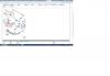
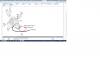
Самого датчика на грибок я в каталоге не нашел. На картинках обвел красным непонятные места.
| Code | Fault Location | Probable Cause |
|---|---|---|
| P02E9 | Diesel Intake Air Flow Position Sensor Circuit High (Buy Part On Amazon) |
Wiring, IAF Position Sensor, PCM |
We recommend Torque Pro
Table of Contents
- What Does Code P02E9 Mean?
- What are the common causes of code P02E9?
- What are the symptoms of code P02E9?
- How do you troubleshoot code P02E9?
- Codes Related to P02E9
- Get Help with P02E9
What Does Code P02E9 Mean?
OBD II fault code P02E9 is a generic code that is defined as “Diesel Intake Air Flow Position Sensor Circuit High”, or sometimes, and depending on the manufacturer, as “Intake Air Flap Control Actuator Position Sensor – Circuit High”. Both definitions have the same basic meaning, which is that the PCM (Powertrain Control Module) sets code P02E9 when it detects an abnormally high voltage in the control circuit of the Intake Air Flow Position Sensor on diesel engines that use these devices.
Note however that the code setting parameters and conditions vary between manufacturers, with “high” voltages ranging from 4.75 volts on some applications, to as high as 4.95 volts on others, which voltages must be present for periods ranging from three to five consecutive seconds before the code is set, depending on the application.
Intake-air flow control mechanisms are a relatively recent development on modern diesel engines, and the main function of these devices is to restrict the intake airflow in some situations to increase the effectiveness of the EGR (Exhaust Gas Recirculation) system, and by extension, the effect that introducing exhaust gas into the combustion chamber has on the reduction of harmful diesel exhaust emissions like nitric oxide and nitrogen dioxide, collectively known as NOx.
While EGR systems have been in use for decades, the technology can no longer satisfy the requirements of ever-more stringent emission control regulations. To comply with new regulations, manufacturers have introduced ways and means to increase the effectiveness of their EGR systems, one of which is to create a vacuum in the intake manifolds of their diesel engines. It must be borne in mind at this point that diesel engines are not throttled like gasoline engines on the one hand, and that unlike gasoline engines, the air/fuel mixture on diesel engines can vary from a about 15 parts of air to one part of fuel, to as many as 60 parts of air to one part of fuel in some situations, on the other.
Moreover, since the power output of diesel engines is determined by the amount of fuel injected (as well as when the fuel is injected relative to the pistons’ position in their upward travel), as opposed to the amount of “fuel enrich-able” air that is available in the inlet manifold of a gasoline engine, there is always an excess of air in the inlet manifold of a diesel engine. Put in another way, a diesel engine simply takes the amount of air it needs to combust the diesel fuel being injected at any given moment from the intake manifold, since there is no need to balance the volume of available intake air with the volume of fuel being injected into each cylinder.
However, in some situations, this situation causes the formation of NOx when the combustion temperature approaches, or reaches 2 700°F (1 500°C). By introducing exhaust gas into the cylinder via the EGR system, the combustion temperature can be kept below the level where NOx forms, but in older diesel engines, poor atomization of the fuel coupled with poor mixing of the intake air and partially atomized fuel reduce the quenching effect of the introduced exhaust gas.
To overcome these shortcomings, manufacturers have increased injection pressures to around 1 500 bar (21 755 PSI) to improve atomization, which is further improved by increasing the number of injection events to up to six during each injection cycle. However, to increase the rate at which intake air enters the combustion chamber in order to improve the mixing of the air/fuel mixture, manufacturers have introduced adjustable restrictions in the intake manifold. While these restrictions resemble throttle bodies on gasoline engines in that that they consist of a moveable plate that looks like a conventional throttle plate, their sole function is to restrict the volume of air that flows into the manifold when it is partially closed.
The effect of the restriction is to increase the speed at which the air flows through the manifold, which in turn, creates a small vacuum, or negative pressure. Thus, by increasing the airflow velocity, “swirl”, or mixing of the air, fuel, and exhaust gas (when it is introduced) is greatly improved. The result of this is twofold; temperature differences in the combustion flame are reduced, resulting in more complete combustion, and when exhaust gas is introduced, the gas mixes with the air/fuel mixture more evenly, which means that the quenching effect of the exhaust gas is distributed more evenly throughout the combustion flame, thereby reducing the formation of NOx.
The nett result of all of the above is better fuel economy and a significant reduction in the formation of harmful NOx over a wider range of engine operating conditions than was possible before the introduction of intake-air flow control devices.
Nonetheless, despite the proven advantages of intake-air flow control systems on diesel engines, these systems have to be in perfect working order for their advantages to be realized. For example, if the actual position of the restricting plate does not agree with the desired position, the engine can either be starved of air when the manifold is restricted too much, or the velocity of the intake air can be slowed down to the point where efficient mixing of the air and fuel (or exhaust gas) no longer takes place.
Both conditions can increase fuel consumption and exhaust emissions, which is why intake-air flow control devices are fitted with position sensors to allow the PCM to calculate a suitable intake manifold restriction to match the engine speed and load at any given moment to ensure maximum engine performance at all times. Thus, when the PCM detects a problem in the intake-air flow control actuator, or its control system (which includes the position sensor), it will set a trouble code, and illuminate warning light.
The image below shows the location of the intake airflow control flaps (indicated by the red arrows) on a BMW diesel application. On applications like this, the individual flaps are linked to a common actuator via a single or common control rod or linkage, and one position sensor on the actuator will serve to indicate the actual position of the control flaps to the PCM. Note however that on some applications, there may be only control flap in the plenum of the intake manifold that serves to control the flow of intake air throughout the entire manifold.
What are the common causes of code P02E9?
Common causes of code P02E9 are much the same across all applications, and these could include the following-
- Damaged, burnt, shorted, disconnected, or corroded wiring and/or connectors
- Defective position switch
- Poor electrical contact or corrosion in the PCM connector.
- On applications where the position senor shares a reference voltage circuit with other engine sensors, failure of, or malfunctions in one or more of the sensors involved could cause P02E9 to set, or contribute to its setting.
- Failed or failing PCM. Note that this is a rare event, and the fault must be sought elsewhere before any controller is replaced.
What are the symptoms of code P02E9?
Apart from a stored trouble code and illuminated warning light, other common symptoms of code P02E9 varies between applications and manufacturers. However, some common symptoms could include the following-
- Reduced fuel economy
- Depending on the application and the nature of the problem, there may a slight loss of power at some engine speeds and loads
- Depending on the application and the exact nature of the problem, there may be rattling sound from the inlet manifold (caused by the uncontrolled opening and closing of control flaps), when the engine is first started, or switched off. Note however that while this symptom is not usually associated with code P02E9, it has been known to occur on some Ford applications when P02E9 is present.
- On some applications, the engine may not switch off smoothly. Some drivers report this as a “prolonged shuddering” of the engine after switching off the ignition
NOTE: Code P02E9 seldom produces serious drivability issues when there are no other codes present along with P02E9. Therefore, if the application displays serious driveability concerns and/or issues and there are other codes present as well, the causes of the driveability issues are likely to the result of one or more of the other codes, especially in cases where the intake air flow control actuator position sensor shares a reference voltage circuit with one or more other engine sensors, as is the case with some Dodge applications.
How do you troubleshoot code P02E9?
NOTE: Apart from a suitable scanner/code reader and a good quality digital multimeter, a color-coded wiring diagram may prove useful in diagnosing this code.
Step 1
Record all fault code present, as well as all available freeze frame data. This information could be useful should an intermittent fault be diagnosed later on.
NOTE: If other codes are present along with P02E9, note them down, and pay particular attention to the order in which they were stored. Refer to the manual for the application being worked on for detailed information on the definitions of all codes present, as well as on the possible relationship between all additional codes and P02E9, since some additional codes can be the direct cause of this code, or may have contributed code P02E9 being set.
Step 2
In cases where other codes are present as well, consult the manual for the application to determine if any additional codes are in any way related to P02E9 and especially in cases where driveability issues are present.
Note however, that while the manual may not provide any information on the possible relationship between additional codes and P02E9, the presence of driveability related symptoms almost always indicates the fact that the position sensor on the intake-air control actuator shares its reference voltage circuit with one or more other engine sensors. Therefore, if a short circuit (either to ground or battery voltage) exists in the shared circuit, multiple sensors can be affected, which can produce drivability issues such as stalling, hard starting, stumbling or hesitation upon acceleration, rough idling, fluctuating idling speeds, and several others, depending on the application.
Engine sensors that might share a reference voltage circuit could include the Fuel Rail Pressure Sensor, Crankcase Pressure Sensor, Camshaft Position Sensor, Inlet Air Pressure Sensor, Exhaust Differential Pressure Sensor, Boost Pressure Sensor, and sometimes, the Radiator Fan Control. Note that not all of the sensors listed here will always share a reference voltage circuit, and that on some applications, some sensors not listed here might share a reference voltage circuit. Therefore, the manual for the application should always be consulted on which engine sensors (if any) are sharing a reference voltage circuit before a diagnosis and/or repair of P02E9 is attempted.
Step 3
If it turns out that several sensors are sharing the intake-air control actuators’ position switch reference voltage circuit, consult the manual further to determine the location of each sensor, as well as the routing, function, and color coding of all relevant wiring. Consult the manual on the correct procedure(s) to follow to test the control/reference voltage circuit for each implicated sensor until the short circuit or other problem is found and corrected.
WARNING: Note that failure to do this will almost certainly cause inexperienced mechanics (both non-professional and otherwise) to conclude that the PCM is defective-, which it very rarely is.
Clear all codes after repairs are complete, and complete at least one drive cycle before scanning the system again to see if the fault returns.
Step 4
If no other codes are present along with P02E9, or if the position sensor does not share a reference voltage circuit with other engine sensors, things become a lot easier and less complicated. In these cases, consult the manual to locate and identify all relevant components, as well as to determine the location, function, color-coding, and routing of all relevant wiring.
Perform a thorough visual inspection of all wiring, and look for damaged, burnt, shorted, disconnected, or corroded wiring and/or connectors. Make repairs as required, clear all codes, and rescan the system to see if the code returns.
Step 5
If the code persists, but there is no visible damage to the sensors’ wiring, prepare to perform reference voltage, resistance, ground connectivity, and continuity tests on the relevant wiring. Be sure however to disconnect the wiring from the PCM to prevent damage to the controller.
Pay particular attention to the reference voltage circuit between the PCM and the sensor connector. All electrical values is this circuit must agree with the values stated in the manual- if any value does not agree, repair or replace wiring as required to ensure that ALL electrical values conform to the manufacturer’s specifications.
Also, compare all obtained readings for the signal and other circuits with the values stated in the manual, and make repairs, or replace wiring and/or connectors as required to ensure that all electrical values conform to specified values.
NOTE: The position sensor itself forms part of the control circuit, so refer to the manual for detailed information on the correct procedure(s) to follow to test the operation of the sensor. Replace the sensor if any test produces results that do not agree with specified values.
Clear all codes after repairs are complete, and complete at least one drive cycle before scanning the system again to see if the fault returns.
Step 6
If the fault persists despite all electrical values falling within the manufacturers’ specifications, suspect a problem with the control device itself, or a problem with the PCM. Bear in mind though that the PCM is unlikely to have failed, so proceed to test the operation of the actuator, which is usually a stepper motor, since diesel applications generally do not use vacuum to operate or control anything except the brake system, which uses vacuum from a dedicated vacuum pump.
Testing procedures vary between applications, so be sure to consult the manual on the correct procedure to follow during this step, which generally involves checking to see that the actuator moves feely throughout its full range of movement. Keep in mind however, that code P02E9 refers to an issue in the control circuit of the position sensor (as opposed to anything else), so if the actuator is sticking or binding, this will almost certainly be indicated by an actuator related “range or performance” code, which might still be in the “pending” stage. Refer to the NOTE in Step 1 on the importance of resolving other codes before attempting a diagnosis and/or repair of P02E9.
Step 7
The steps outlined up to this point will resolve code P02E9 in nine instances out of every ten, but if the fault persists, or returns after a few drive cycles, it is likely that an intermittent fault is causing the problem, Be aware though that intermittent faults can be extremely challenging and time consuming to find and repair and in some cases, it may be necessary to allow the problem to worsen considerably before an accurate diagnosis and definitive repair can be made.
NOTE: While it is rare for mechanical failures of the airflow control device to cause code P02E9, it is not altogether impossible. If this is suspected to be the case, bear in mind that repairing such failures may require removal and disassembly of the intake manifold, which more often than not, is a task best left to professional repair shops, since performing this procedure often requires special tools/equipment and skills that many non-professional mechanics do not possess.
P02E8 – Relates to “Diesel Intake Air Flow Position Sensor- Circuit Low”
Help Us Help You
Please comment below describing your issue as well as the specifics of your vehicle (make, model, year, miles, and engine),
and one of our mechanics will respond as soon as possible. We appreciate a $9.99 donation via the payment button below.
Автор:
Robert Doyle
Дата создания:
20 Июль 2021
Дата обновления:
21 Июнь 2023

Содержание
- Возможные причины
- Возможные симптомы
- P02e9 Ford Описание
Возможные причины
Возможные симптомы